1
v
.
E- STANDING TEST EQUIPMENT,
UI II
U
Part
I- FREQUENCY COUNTERS
$1.25
IN CANADA
Sl
50
lElectronîc
NOVEMBER DECEMBER 1979
a
023u
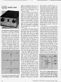
¡PARAPARALLELOGRAM
LLELOGRAM
E'OW TIE
I
ACUTE TRIANGLE
F
MOCLI ATION
TRIANGLE
Build an
STRAIGHT LINE
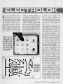
Electronic Lock
You Can Program
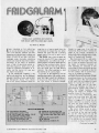
Frill alarm Keeps
Out Dieters
SPOTLIGHT
SLOW
MIXER
10
twave Receivers
Tuners
Finco
-Yaesu
t
Whip
3G
mputer
IS
A
DAVIS PUBLICATION
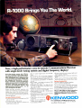
Now, a high- performance, easy-to- operate Communications Receiver
with single -knob tuning system and digital frequency display!
Up- to-the- minute events and information from anywhere in the world, includ-
ing foreign shortwave broadcast (music,
news, propaganda, etc.), emergency ship
communications and other marine traffic, standard AM broadcast, Amateur
Radio Operators, all 40 CB channels,
military and government messages, long-
distance industrial communications,
standard time /frequency signals...and
other exciting transmissions... it's all
yours through the R-1000!
Highly accurate, sensitive, selective, and
fast -tuningg
q
stable, the R 1000 has a unique
system that covers the shortwave bands,
plus medium wave and long wave free
cies. Even SSB communications signals are
received perfectly.
many features Include:
ontinuous frequency coverage from 200
kHz to 30 MHz
30 bands, each 1 MHz wide
Accurate five -digit frequency display and
illuminated analog dial
Built -in quartz digital clock and ON /OFF
timer
Up- conversion PLL circuit and wideband
RF circuits provide, exceptional performance and easy operation without the need
for bandspread, preselector, or antenna
tuning
Multi -modes...AM (wide and narrow), SSB
(USB and LSB), and CW
Three built -in IF filters...for SSB and CW
(2.7 kHz), for AM narrow (6.0 kHz), and for
AM wide (12 kHz)
Effective communications -type noise
Dimmer switch to control panel lights and
digital display intensity
Adjustable bracket for optimum operating
angle
Three antenna terminals for high- impedance wire leads and a 50 -Q coaxial lead
Optional Accessories:
SP -100
matching external speaker
HS -4 and HS -5 headphones
The exciting R 1000 is designed specifically
for those who demand the highest quality
uam
and it's available only through selected corn-
munications equipment specialists.
blanker (superior to noise limiter)
Write or call today for more information
steps)
-dB
in
20
dB
-60
Step attenuator (0
and for the address of your nearest
to prevent overload
Authorized Kenwood Communications
Recording terminal (built -in timer controls
Dealer.
recording time through remote
terminal)
Tone control for best audio
res onse
Builltt -in 4 -inch speaker for
TRIO -KENWOOD COMMUNICATIONS INC.
quality sound reproduction
1111 WEST WALNUT COMPTON, CA 90220
S
-meter
Illuminated
(213) 639-9000
KENWOOD
TELEPHONE:
Now there's finally a scanner for those who simply will not
settle for anything less than everything. We call it the
Touch K500. And we've included everything it takes to make
public service band scanning more enjoyable and more
exciting than ever.
If you want it all, the place to start is with all the frequencies.
The Touch K500 covers each one by searching. It's like tuning
the dial on an ordinary radio, but much more precise and
versatile. You see, when it hears something, you don't have
to remember a thing. Just keep on searching and enjoying.
Later you can go back and
ask the memory to recall the
active frequencies. It never
,MIWSEC,
forgets.
2 3
5
Now, if you're into scanning,
UPPER
you know that sometimes a
scanner will miss some calls
AlERT11
you want to hear. Remember
what we said about
PM
everything? With the Touch
DEI AV,
K500 you can stick around
for a reply to a call by
delaying scan resumption for up to 4 seconds. If you need
more time, you can program an indefinite hold.
You'll never have to miss calls on your favorite frequency
either. Just touch priority and the Touch K500 will sample
channel 1 every 1.5 seconds. Another feature to interrupt
E
C
things is the Weather Alert® we've included to
respond to severe weather alerts direct from the National
Weather Service.
"Everything" is a big subject. We're just beginning. Next
consider the scan channels: all 585 of them. We built -in an
amazing 40 RAM* channels for conventional touch entry
crystalless scanning. But even that's not enough for you. So
we gave it 545 ROM* channels that let you scan just by
selecting the type of frequency you want to hear. Touch the
flasher symbol for police, the flame for fire or the sailboat
for marine, weather, or mobile phones. The Touch K500 will
cover any common frequency in the ROM set you select.
There's also an LED quartz clock with an alarm. A counter
that tallies the number of times a channel is used. Plus a
device that can remotely activate electrical equipment.
To really experience it all, see your Regenéy retailer. When it
comes to scanners, he has everything.
The scanner
for those who won't
settle for anything less
than everything.
TOUCH K500
w
maim
®000 00000®
1,31*
1110(n.7d0
Regency Electronics, Inc.
_
.
$
oC
a
7707 Records St. Indianapolis, IN 46226
.
'RAM: Regency Alterable Memory
'ROM: Regency Organized Memory
CIRCLE 23 ON READER SERVICE COUPON
ELEMENTARY ELECTRONICS / November -December 1979
1
November /December 1979
Volume 19, No. 6
THE STAFF
Associate Publisher &
Editor-in -Chief
Julian S. Martin
Managing Editor
Alan H. Rose, K2RHK
Technical Editor
Gordon Sell, KBDA1464
Associate Editor
Lee Lensky, KA2DKT
Citizens Band Editor
Kathi Martin, KGK3916
Editorial Assistant
Cynthia McClean, KBKF3780
Workbench Editor
Hank Scott
Art Director
Ralph Rubino
Associate Art Director
David Pindar
Assistant Art Director
Michael Vessio
Cover Art Director
eiectronics
**
**
Production Director
Carl Bartee
Production Manager
Carole Dixon
Production Assistant
Edith Muesing
Newsstand Circulation
Director
Don Gabree
Subscription Circulation Director
Robert V. Enlow
Subscription Circulation Manager
Eugene S. Slawson
Marketing Director
James C. Weakley
President and Publisher
Joel Davis
Vice President and
General Manager
Leonard F. Pinto
Vice President and Treasurer
Victor C. Stabile, KBP0681
ISSN: 0013 -595X
ELEMENTARY ELECTRONICS is published bi- monthly by Davis Publications, Inc. Editorial and Executive offices: 380 Lexington Ave., New York,
NY 10017; all subscription orders and
mail regarding subscriptions should
be sent to P.O. Box 2630, Greenwich,
CT 06835. In U.S.A. and possessions,
one -year subscription (six issues)
$6.95; two -year subscription (12 issues) $12.95; three years (18 issues)
$18.95; and four years $23.95. Elsewhere, add $1.00 postage for each
year. For change of address, please
advise 6 to 8 weeks before moving.
Send us your current mailing label
with new address. Advertising offices:
East Coast; 380 Lexington Ave., New
York, N.Y. 10017, 212 -557 -9100; Midwest; 360 N. Michigan, Suite 1022,
Chicago: IL 60601, 312- 527 -0330; West
Coast; J. E. Publishers' Rep. Co., 8732
Sunset Blvd., Los Angeles, CA 90069,
213 -659 -3810. Controlled Circulation.
Postage paid at New York, New York,
and Sparta, Illinois. Copyright 1979 by
Davis Publications Inc.
2
41
44
56
67
73
SHORTWAVE RADIO CHECKPOINTS
37 A Short Course in Shortwave Receivers -inside the newest shortwave radios
42 Signal Propagation -with the latest aids, you can predict band conditions like a
professional
Irving Bernstein
Art Assistants
Delia Nobbs
Susan Mahler
Advertising Director
Ralph Vega
CONSTRUCTION PROJECTS YOU CAN BUILD
-tell time in binary numbers
Fridgalarm- reminds you to stay out of the ice box
Electrolok-keep valuables safe electronically
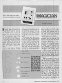
(magician-analog generator makes your 'scope a work of art
Electronic Slot Machine -build your own one -armed bandit with a few ICs
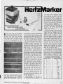
HertzMarker- simple circuit generates accurate frequency standards
33 BCD Clock
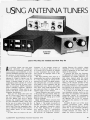
49 Using Antenna Tuners -this is the best thing that can come between your rig and your
antenna
*
CONTINUING WITH COMPUTERS
52 Simply Basic -block construction saves memory space
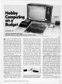
53 Home Computing on a Budget-OS/ Superboard II offers full features at lowest prices
about video graphics displays
61 Computer Readout
74 The Source-hook your computer to an information network
-all
KEEPING AN EYE ON THE NEW TECHNOLOGY
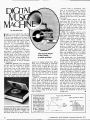
64 Digital Record Player-new playback techniques could revolutionize hi -fi
71
*
*
*
^,
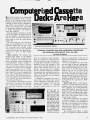
Computer Cassette Decks -microprocessor models obey your slightest wish
BASIC COURSE IN TEST EQUIPMENT
-the origins, theory, and uses of Frequency Counters
75 Section One
NEW PRODUCTS ON THE TEST BENCH
... Avanti AH 151.3G Two -meter Antenna-revolutionary whip
mounts through glass
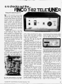
63 e/e checks out the ... Finco T -82 Teletuner -get hi -fi sound from your TV at last
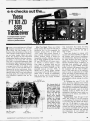
69 e/e checks out the ... Yaesu FT -101 ZD SSB Transceiver -new features in the latest
of an established Amateur line
60
e/e checks out the
OUR REGULAR DEPARTMENTS
-keep up -to -date with the latest products
-look at the wide world of automobile hi -fi
8 Hey, Look Me Over
12 Hi -Fi Reports
17
22
24
55
65
88
Bookmark -by Bookworm
DX Central -more inside info about the shortwave world
Newscan -new technology in the making
Kathi's CB Carousel -Kath/ conjectures about CB's future
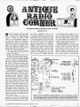
Antique Radio -Jim Fred shows how to rebuild those old -time speakers
/e's old problem- solver tackles some toughies
Ask Hank, He Knows
-e
Cover Stories.
c
0
elementary
nn
z
1.1.17U.
OF
AUTHORS IN THIS ISSUE
Fred Blechman, Jim Fred, Herb
Friedman, Larry Friedman, Morrie Goldman, Don Jensen, Kathi
Martin, Ed Noll, Bob Powers,
Winn Rosch, Hank Scott, Gordon
Sell, Walter Sikonowiz, Tom
Sundstrom, Martin Weinstein,
Tom Williams.
ELEMENTARY ELECTRONICS / November -December 1979
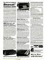
The World's biggest
NEW!
INCREASED PERFORMANCE ANTENNAS
Aircraft Bearcat 220
If you want the utmost in performance from yourBearcat
scanner, it is essential that you use an external antenna.
Bearcat®
We have four base and mobile antennas specifically
designed for receiving all bands. Order #A60 is a
magnet mount mobile antenna. Order #A61 is a gutter
clip mobile antenna. Order #A62 is a trunk-lip mobile
antenna and #A70 is an all band base station antenna.
All antennas are $25.00 and $3.00 for UPS shipping in
the continental United States.
scanner sale!
Communications Electronics; the world's
largest distributor of radio scanners, celebrates the introduction of four new Bearcat
brand monitors with the world's largest scanner
sale. From now, until January 31,1980, you can
save hundreds of dollars during our two-million
dollar Bearcat sale. Even the new Bearcat
models 300, 220 and Eight Track scanners are
on sale. If you've previously purchased a Bearcat scanner from Communications Electronics,
then you already know you're getting all the
real, live excitement that a television program
or newspaper can't provide. If you don't have at
least one Bearcat scanner, the time to buy is
now! Since we distribute more scanners worldwide than anyone else, we can sell the newest
factory production models with the latest engineering updates, at rock bottom prices. Our
warehouse facilities are equipped to process
over 1,000 Bearcat orders per week and our
order lines are always staffed 24 hours. We also
export Bearcat scanners to more than 300
countries and military installations. Almost all
items are in stockfor immediate shipment, so
save now and get a Bearcat scanner during the
world's largesttwo- million dollar scanner sale!
NEW!
Bearcat® 300
Available February - March, 1980
List price $499.95/CE price $329.00
50 Channel Service Search Nocrystal scanner AM Aircraft and Public
Service bands. Priority Channel AC/DC
7 -Band,
Bands: 32 -50, 118-136 AM, 144-174, 420.512 MHz.
The new Bearcat 300 is the most advanced automatic scanning radio that Communications
Electronics has ever offered to the public. Since
the Bearcat 300 has over 2,100 active frequencies
in memory, you can touch one button and search
any of many preprogrammed services such as
police, fire, marine and government. Of course, you
still can program your own frequencies and monitor
up to 50 channels at once. Since the Bearcat 300
uses a bright green flourescent digital display, it's
ideal for mobile applications. The Bearcat 300 now
has these added features: Service Search, Display
Intensity Control, Hold Search and Resume Search
keys, Separate Band keys to permit lock -in /lockout of any band for more efficient service search
and a new vacuum fluorescent digital display.
Reserve your Bearcat 300 now for February March, 1980 delivery.
Bearcat® 250
List price $399.95/CE price $259.00
50 Channels
Crystalless Searches
Stores Recalls Self -Destruct Priority
channel 50 Channel 6-Band.
Frequency range 32 -50, 146 -1 74, 420-512 MHz.
The Bearcat 250 performs any scanning function you
could possibly want. With push button ease you can
program up to 50 channels for automatic monitoring.
Push another button and search for new frequencies.
There are no crystals to limit what you want to hear. A
special search feature of the Bearcat 250 actually
stores 64 frequencies, and recalls them, one at a time,
at your convenience. Automatic "count" remembers
how often frequencies are activated by transmission so you know where the action is. Decimal display shows
the channel, frequency and other programmed features. The priority feature samples your programmed
frequency every two seconds. Plus, a digital clock
shows the time at the touch of a button. This is the only
monitor radio that has received the Communications
Electronics quality control approval rating #1. Our
highest quality grade for technologically sophisticated
equipment. The Bearcat 250. Scanning like you've
never seen or heard before. Now in stock!
OTHER BEARCAT ACCESSORIES
$12.00
$12.00
$15.00
$15.00
SP57 Carrying Case for ThinScan
manual
for
Bearcat
210
SM21 O Service
$15.00
SM220 Service manual for Bearcat 220
$15.00
$15.00
SM250 Service manual for Bearcat 250
$15.00
B -31.2 V AA Ni -Cad's for Four-Six (Pack of 4)
$15.00
B -41.2 V AAA Ni -Cad's for ThinScan (Pack of 4)
B -5 Replacement memory battery for Bearcat 210 .... $5.00
$4.00
A -135cc Crystal certificate
Add $3.00 shipping for all accessories ordered at the same time.
SP5O AC Adapter
SP51 Battery Charger
SP55 Carrying Case for Four-Six
Aircraft Bearcat® 220
List price $399.95/CE price $259.00
Aircraft and public service monitor. Frequency
range 32 -50, 118 -136 AM, 144 -174, 420-512 MHz
The Bearcat 220 is one scanner which can monitor all
public service bands plus the exciting aircraft band
channels. Up to twenty frequencies may be scanned at
the same time.
Not only does this new scanner feature normal search
operation, where frequency limits are set and the
scanner searches between your programmed parameters, it also searches marine or aircraft frequencies by
pressing a single button. These frequencies are already
stored in memory so no reprogramming is required. The
Bearcat 220 also features a Priority channel, Dual scanning speeds, Patented track tuning and Direct channel
access and AC /DC operation.
New! Bearcat® 211
List price $339.95/CE price $229.00
Frequency range: 32 -50, 146-174, 420-512 MHz.
The Bearcat 211. It's an evolutionary explosion of
features and function. 18- channel monitoring. With nocrystal six-band coverage. Dual scan speeds. Color coded keyboard. Even a digital clock. All at a modest
price. More scanning excitement than you bargained for.
Bearcat®
210
List price $299.95/CE price $199.00
10 Channels
5 Bands
Crystalless
Frequency range: 30-50, 146 -174, 416 -512 MHz.
Use the simple keyboard to select the 10 channels to be
scanned. Automatic search finds new frequencies. The
210 features patented selectable scan delay, push
button lockout, single antenna, patented track tuning,
AC/DC operation. With no crystals to buy. Ever!
NEW!
Bearcat® 8 Track
List price $99.95/CE price $79.00
Channels
2 Bands Plays off any AC or DC
Powered 8 Track Tape Player. Frequency range:
33 -49, 151 -165 MHz.
The Bearcat 8 Track Scanner. It converts any 8 track
tape player into a live- action scanning radio instantly.
This incredibily compact 4- channel /2 -band crystal
scanner plugs into the tape player where an 8 track
-
cartridge normally goes. Police, fire, emergency calls
as-it- happens scanning excitement-from an existing
home entertainment center, in- car /in -boat system or
portable 8 track tape player. The Bearcat 8 Track
Scanner plugs live- action into any 8 track player. Anywhere. Crystal certificates # A-135 cc are $4.00 each.
Bearcat® Four -Six
List price $169.95/CE price $109.00
The first 4 Band, 6 Channel, Hand -Held Scanner.
Frequency range: 33-47, 152-164, 450-512 MHz.
The Bearcat Four -Six offers "hip pocket" access to
police, fire, weather and special interest public service
broadcasts. Lightweight. Extremely compact. The Bearcat Four-Six-with its popular "rubber ducky" antenna
and belt clip- provides "go anywhere /hands-off' scanning.
NEW! Aircraft and UHF
Bearcat® ThinScan'"
List price $149.95/CE price $99.00
World's smallest scanner!
The Bearcat ThinScan" High -performance scanning
has never been this portable. There are now three
models available. The BC 2-4 LJH receives 33 -44 and
152 -164 MHz. The BC 2-4 H/U receives 152 -164 and
450 -508 MHz. The new high-performance Aircraft
ThinScan model BC 2 -4 AC receives 118 -136 and 450470 MHz. Go ahead, size it up. Bearcat's ThinScan"
measures 2a/. " across. Just 1" deep. And 5%" high.
Four crystal -controlled channels are scanned every 1/2
second providing immediate access to police, fire,
weather and other special- interest broadcasts.
TESTA BEARCAT SCANNER FREE
Test any Bearcat brand scanner from Communications
Electronics" for 31 days before you decide to keep it. If
you do, you'll own the most sophisticated and technologically advanced scanner available. If for any reason you
are not completely satisfied, return it in new condition
with all accessories in 31 days, for a courteous and
prompt refund (less shipping charges).
NATIONAL SERVICE
With your Bearcat scanner, we will send all accessories, a complete set of simple operating instructions
and a one-year limited warranty. If service is ever
required on any Bearcat scanner purchased from
Communications Electronics; just send your receiver to a CE approved Bearcat national service center.
Another Bearcat service is the frequency information
hotline. After you get yourscannerfrom CE, you maycall
317-894 -1230 and get up to the second information on
active frequencies in your area If you ever need
engineering assistance, feel free to call the factory
during the day at 317-894-1440.
BUY WITH CONFIDENCE
All Bearcat scanners are extraordinary scanning instru-
ments. They provide virtually any scanning function that
the most professional monitor could require. To getthe
fastest delivery of any Bearcat scanner, send or
phone your order directly to our Scanner Distribution
Center" Be sure to calculate your price using the CE
prices in this ad. Michigan residents please add 4%
sales tax. Written purchase orders are accepted from
approved government agencies and well rated firmsata
10% surcharge for net 30 billing. All sales are subject to
availability. Prices and specifications are subject to
change without notice. Out of stock items will be placed
on backorder automatically unless CE is instructed
differently. International orders are invited with a
$10.00 surcharge for special handling in addition to
shipping charges. All shipments are F.O.B. Ann Arbor,
Michigan. No COD's please. Cashier's checks will be
processed immediately and receive an order priority
number. Personal checks require three weeks bank
clearance. Mail orders to: Communications Electronics; Box 1002, Ann Arbor, Michigan 48106 U.S.A. Add
$5.00 per scanner for U P.S. ground shipping, $9.00 for
faster U.P.S. air shipping or $30.00 for overnight
deliveryto most major U.S.cities via Airborne Air Freight.
If you have a Master Charge or Visa card, you may call
anytime and place a credit card order. Order toll free
800 -521 -4414. If you are outside the U.S. or in Michigan, dial 313-994 -4444. Dealer Inquiries invited. All
order lines at Communications Electronics" are
staffed 24 hours.
Since this two -million dollar Bearcat sale
is the world's largest, please order today at no
obligation to assure a prompt order confir-
mation and delivery.
When you follow the Nader to real excitement,
your Journey ends at Communications Electronics.
Autoprogramming" Scanner Distribution Center" and
CE logos are trademarks of Communications Electronics"
Copyright °1979 Communications Electronics"
master charge
//COMMUNICATIONS
ELECTRONICSLECTRON ICS'°
854 Phoenix Box 1002 0 Ann Arbor, Michigan 48106 U.S.A.
Call TOLL FREE (900)321 4414 or outside U.S.A. (3131994-4444
NEW! 50- Channel
Bearcat 300
NEW!
Bearcat 8 Track scanner
CIRCLE 108 ON READER SERVICE COUPON
ELEMENTARY ELECTRONICS / November -December 1979
We're first
with the best:M
3
"If you're going to learn
electronics, you might
as well learn it right!"
Don't settle for less.
Especially when it comes
to career training.. because
everything else in your life
may depend on it. That's
why you ought to pick CIE!"
4
ELEMENTARY ELECTRONICS
November- December 1979
you've probably seen advertisements from other
electronics schools. Maybe you
think they're all the same.
They're not:
CIE is the largest independent home study school in the
world that specializes exclusively in electronics.
Pick the pace that's right
for you.
CIE understands people need
to learn at their own pace. There's no
pressure to keep up ... no slow
learners hold you back. If you're a
beginner, you start with the basics.
If you already know some electronics, you move ahead to your
own level.
Meet the Electronics
Specialists.
When you pick an electronics
school, you're getting ready to invest
some time and money. And your
whole future depends on the education you get in return.
That's why it makes so much
sense to go with number one with
the specialists ... with CIE!
.
.
There's no such thing as
bargain education.
If you talked with some of our
graduates, chances are you'd find a
lot of them shopped around for their
training. Not for the lowest priced
but for the best. They pretty much
knew what was available when they
picked CIE as number one.
We don't promise you the moon.
We do promise you a proven way to
build valuable career skills. The CIE
faculty and staff are dedicated to
that. When you graduate, your diploma shows employers you know
what you're about. Today, it's pretty
hard to put a price on that.
Enjoy the promptness of
CIE's "same day" grading
cycle.
When we receive your lesson
before noon Monday through Saturday, we grade it and mail it back
the same day. You find out quickly
how well you're doing!
-
CIE can prepare you for
your FCC License.
For some electronics jobs, you
must have your FCC License. For
others, employers often consider it a
mark in your favor. Either way, it's
government -certified proof of your
specific knowledge and skills!
More than half of CIE's courses
prepare you to pass the governmcntadministered exam. In continuing
surveys, nearly 4 out of 5 CIE graduates who take the exam get their
Licenses!
For professionals only.
CIE training is not for the hobbyist. It's for people who are willing to
roll up their sleeves and go to work
to build a career. The work can be
hard, sure. But the benefits are
worth it.
.
Send for more details
and a FREE school
catalog.
Mail the card today. If it's gone,
cut out and mail the coupon. You'll
get a FREE school catalog plus complete information on independent
home study. For your convenience,
we'll try to have a CIE representative contact you to answer any questions you may have.
Mail the card or the coupon or
write CIE (mentioning name and
date of this magazine) at: 1776 East
17th Street, Cleveland, Ohio 44114.
Because we're specialists, we have to stay
ahead.
At CIE, we've got a position of
leadership to maintain. Here are
some of the ways we hang onto it ...
Our step -by-step learning
includes "hands -on"
training.
At CIE, we believe theory is
important. And our famous
Auto-Programmed® Lessons teach
you the principles in logical steps.
But professionals need more
than theory. That's why some of our
courses train you to use tools ofthe
trade like a 5 MHz triggered- sweep,
solid -state oscilloscope you build
yourself- and use to practice traubleshooting. Or a beauty of a 19 -inch
diagonal Zenith solid -state color TV
you use to perform actual service
operations.
Patterns shown on TV and oscilloscope screens are simulated.
I
CIE
1776 East 17th Street, Cleveland, Ohio 44114
Accredited Member National Home Study Council
...
YES
I want the best of everything! Send me my FREE CIE school
catalog including details about troubleshooting courses -plus my FREE package
of home study information.
EL-It
Print Name
-
Our specialists offer you
personal attention.
Sometimes, you may even have
a question about a specific lesson.
Fine. Write it down and mail it in.
Our experts will answer you
promptly in writing. You may even
get the specialized knowledge of all
the CIE specialists. And the answer
you get becomes a part of your permanent reference file. You may find
this even better than having a classroom teacher.
Cleveland Institute of Electronics, Inc.
Address
Apt
City
State
Age
,
Check box for G. I. Bill information:
Zip
Phone (area code )
Veteran
Active Duty
MAIL TODAY!
ELEMENTARY ELECTRONICS / November-December 1979
7
ilex
gook me over
Showcase of New Products
Upgrade TRS -80 to 16K RAM
Ithaca Audio has a complete and inexpensive kit for upgrading the Radio
Shack TRS -80 Microcomputer System to
16K RAM. The Ithaca Audio 16K TRS -80
Upgrade Kot supplies everything needed
for fast, reliable memory expansion. The
TRS -80 owner can enlarge the capabilities of his system to include more extensive programming in just minutes,
absolutely no soldering is required. The
kit comes complete with pre- programmed jumper shunts for both Level I and
Level II machines in addition to eight fully- tested 16K dynamic RAMs. These
are simply plugged into the keyboard or
the "point -to- point" mode. It contains a
built -in wire cutoff device for terminating
the final connection of each chain. The
JWK -6 Kit contains the "Just Wrap"
wrapping tool, the JUW -1 unwrapping
tool, and four 50 -ft. wire refill cartridges,
one each in red, white, blue and yellow,
all packaged in a sturdy, reusable clear
plastic box. Priced at $24.95 the JWK -6
Just Wrap Kit is available from stock
at local electronics retailers or directly
from O.K. Machine and Tool Corp., 3455
Conner Street, Bronx, NY 10475.
Moonrotor
Avanti's rotor and control system for
CB and amateur communications, called
the Moonrotor, is a natural companion
to its namesake, the Moonraker, and the
popular P.D.L. II (Polar Diversity Loop)
antennas. Developed with design and
production specialists at Cornell -Dubilier
Electronics, Moonrotor features an advanced solid state control system with
the appearance of a jet aircraft control
panel. Its aluminum housing unit holds
a double row 98 ball bearing support
system. It is driven through steel intermediate and ring gears by a stainless
steel main drive. Moonrotor also features
a four -pole, high- torque electric motor
with a safe low voltage control which
provides turning power for the big beams
-up to 8.5 square feet of wind load
area. The Moonrotor's integrated cirES
CIRCLE 75 ON READER SERVICE COUPON
expansion module of the TRS -80. The
16K TRS -80 Upgrade Kit is now available
nationwide through all Ithaca Audio dealers or can be ordered from any independent computer retailer. The suggested retail price is just $140.00. For more
information, contact Ithaca Audio, P.O.
Box 91, Ithaca, NY 14850.
Just Wrap Kit
Complementing the introduction of its
CIRCLE 70 ON READER SERVICE COUPON
remarkable new Just Wrap wire wrapping
tool, O.K. Machine and Tool Corp. has
announced its new Just Wrap Kit. The
Just Wrap tool wraps 30 AWG wire onto
standard .025 square posts without
cuitry has five preset azimuth memory
circuits positioned by 30 turn potentiometers. A simple flip of the switch actuates precision beam positioning on any
one of the preselected stations. Both
the directional control and the special
azimuth memory circuits are linked to
the integrated circuit which continually
senses antenna location and selects the
shortest direction of rotation to turn to
the desired position. For more information on the Moonrotor, which sells for
$129.95, write to Avanti Research & Development, Inc., 340 Stewart Avenue,
Addison, IL 60101.
CIRCLE 73 ON READER SERVICE COUPON
stripping or slitting the insulation. The
tool can "daisy chain" continuously
through several points or can be used in
8
Futuristic Car Stereo
Panasonic has introduced "Cockpit," a
ceiling- mounted, modular control unit
that offers stereo sound. Cockpit, Model
RM -610, includes a Dolby cassette deck,
in a
FM stereo tuner, and pre-amp
-all
neat, slender console that hangs overhead in the cabin of your vehicle. The
stereo amplifier offers 60 watts total
output power and has a flat frequency
response and total harmonic distortion
of less than .5 %. The FM tuner section
has an automatic multi -path noise suppressor, special RF AMP and double
balanced mixer circuit, high sensitivity
and excellent performance of RF intermodulation distortion, 3 pre-set soft
touch buttons or manual electronic FM
stereo tuning, FM stereo auto /mono
switch and stereo indicator, 16 flash
CIRCLE 42 ON READER SERVICE COUPON
running LED dial frequency indicators,
muting switch, DX/local sensitivity selector, built -in impulse noise quieting
circuit, and an on /off power switch and
noise blanker. The tape deck section has
an auto -reverse cassette player system
with locking fast forward and rewind,
switchable Dolby noise reduction system,
auto eject system when ignition key is
off, normal /CRO., tape selector, lighted
tape direction indicator and volume control. The pre -amp section offers bass and
treble controls with center click, balance
and fader controls with center clock,
volume control with 21 clickstops, loudness switch, and 10 LED Output Power
Indicators. The Cockpit RM -610 sells for
$999.95. For all the facts on the Cockpit and other auto audio products, write
to Panasonic, One Panasonic Way, Secaucus, NJ 07094.
Finding Hidden Treasures
Searching for hidden treasure or lost
valuables is fun and easy with the Micronta Metal Detector, new from Radio
Shack. The new metal detector is ideal
for finding lost coins, relics, jewelry,
keys, hardware or anything metallic. It
works equally well at finding things under water, wood or soil. The Detector
features a water- resistant 8 -inch search
coil with a Faraday shield to eliminate
false indications, a ferrous /non- ferrous
control which optimizes the circuit for
finding magnetic or non -magnetic objects and a large, easy-to -read meter and
adjustable audio alert. The detector has
volume, peaking and sensitivity con -
ELEMENTARY ELECTRONICS
(Continued on page 10)
November -December 1979
Radio Shack -Your No. 1 Parts Place(TM)
Low Prices and New Items Every Day!
Á
49¢
Low
As
100% Prime
Guaranteed Specs
Improved 5 -volt logic devices use
Schottky diode technology for
minimum propagation delay and
high speed at minimum power.
Type
Cat. No.
ONLY
74LS00
74LS02
74LSO4
74LSO8
74LS10
74LS13
74LS20
74LS27
74LS30
74LS32
74LS47
74LS51
74LS73
74LS74
74LS75
74LS76
74LS85
74LS90
74LS92
74LS93
74LS123
74LS132
74LS151
74LS157
74LS161
74LS164
74LS175
74LS192
74LS193
74LS194
74LS196
74LS367
74LS368
74LS373
74LS374
276-1900
276-1902
276 -1904
276 -1908
276-1910
276-1911
276-1912
276-1913
276 -1914
276 -1915
276 -1916
276 -1917
276 -1918
276 -1919
276 -1920
276 -1921
276 -1922
276 -1923
276 -1924
276 -1925
276 -1926
276 -1927
276 -1929
276 -1930
276 -1931
276 -1932
276 -1934
276 -1935
276 -1936
276 -1937
276 -1938
276-1835
276 -1836
276-1943
276-1944
.49
.59
.59
.49
.59
.99
.59
.69
.59
.69
1.29
.59
.69
.69
.99
.79
1.29
.99
.99
.99
1.19
.99
.99
1.19
1.49
1.49
1.19
1.49
1.49
1.49
1.59
1.19
1.19
2.39
2.39
198
AI
Pkg.
of
3
Open -Collector Output
Detects magnetic fields electronically.
750 gauss on threshold. Constant amplitude independent of frequency. Similar
to type ULN 3006. Ideal for tachs, position sensing, pulse counting. 5 to 16V
supply. TO -92 case. With data.
.. Pkg. of 3/1.98
276-1646
V
to
F, F
189
Low
As
to V Converter
Cat. No.
EACH
4001
4011
276-2401
276 -2411
276-2412
276-2413
276-2417
276-2420
276 -2421
276 -2423
276 -2427
276 -2428
276 -2446
276 -2447
276 -2449
276 -2450
276 -2451
276-2466
276 -2470
276-2490
276-2491
.69
.69
.79
.99
1.69
1.69
1.69
.69
.99
4012
4013
4017
4020
4021
4023
4027
4028
4046
4511
4049
4050
4051
4066
4070
4518
4543
All Prime from Major Semi-
conductor Manufacturers.
Specs and Pin Out Diagram
Included with Each Device.
Driver
349
Ideal for Voltage, Current
and Audio Power Displays
LM3914N. Features 10 adjustable analog
steps, bar or dot display mode. Current regulated LED ouputs. 8 to 25VDC
supply. 18 -pin DIP. 276 -1707
3.49
LM3915N. As above but with 3 dB log
3.49
steps. 276 -1708.
10- Position BCD
AC and DC
Switch
Relays
299
34
0
High Linearity and Accuracy
9400CJ. Accepts analog voltage and generates linear proportional output frequency or
provides a voltage output depending on input
frequency. Operates either mode up to 100
kHz. With data. 14 -pin DIP.
3.49
276 -1790
Contacts
Gold- Plated
249
199
SPST Solid State AC Relay. Handles
24 to 280VAC at up to 1.5A. TTL com-
patible 5VDC control input. 1500VRMS
1.99
isolation.275-236
12VDC SPDT. Silver- plated contacts:
2.49
1 A at 125VAC. 275-231
s
NEW!
4"
12/24 -Hr. LCD
Full 0 -9 binary coded outputs for logic Circuits. Eliminates extra encoding circuitry.
Positive detents. Fits standard 8-pin DIP
socket or mounts on PC board.
275 -1310
2.99
NEW!
Cooling Fan
1295
Clock Module
Super
Quiet
Actual Size!
24 -Hour Alarm
Shows Time /Day /Date
-
Complete clock module
just add switches and
battery! 0.25" LCD display has built -in backlight,
alarm set, PM and snooze indicators. Operates
up to year on single 1.5V battery. Accuracy:
19.95
13 seconds per month. 277 -1005
1
1
9
Ideal for cooling power supplies,
microcomputers, hi -fi and Ham
gear. Delivers up to 70 CFM. Die cast vemturi. U.L. recognized
motor. For 120VAC. 60 Hz.
12.95
273-241
.....
Archer' Semiconductor Reference
Handbook
Latest
Edition
199
Available Only at
Radio Shack!
complete guide to Radio
Shack's line of high -quality
solid -state devices. Cross reference and substitution guide
for over 100,000 types. Pin
outs, detailed data for ICs,
diodes, LEDs, SCRs, displays
and more! 224 pages.
276-4003
Only 1.99
A
Manufacturer's Data Books
1.29
1.89
1.69
.79
.79
1.49
1.39
.79
1.49
1.99
LED Bar /Dot Display
0
Feature very high input impedance, low
noise. Fast 13VRS slew rate is ideal for
low TIM distortion audio amplifiers. Internally compensated. Up to -_ 18V
supply.
LF 353N. Dual BIFET Op amp. 8 -pin
1.89
DIP. 276 -1715
s TL 084C. Quad BIFET Op amp
2.99
14 -pin DIP. 276 -1714
4000 -Series CMOS ICs
Type
rir
BIFET Op Amps
Hall- Effect Sensors
Low -Power
Schottky ICs
Low As
295
"Sound and Music
Synthesizer" IC
SN -76477
Need Info?-Find it
at Radio Shack!
299
0
Motorola RF Data Manual. Power and small -signal RF trans's-
s
Motorola Low -Power Schottky TTL. Data and diagrams plus
tors, hybrid amplifier modules, more. 62-1380
4.95
3 95
selection guide for choosing best device. 62-1381
© Linear Applications, Vol. 2. Latest data. diagrams, applications briefs and articles. Indexed. 62 -1374
2.95
D CMOS Integrated Circuits. Covers 74C. CD4000- series with
complete data, diagrams. Cross referenced. 62 -1375
3 95
E Memory Data Book. Complete info on MOS and bipolar memory components, support circuits. 62-1376
3 95
WHY WAIT FOR MAIL ORDER DELIVERY?
IN STOCK NOW AT OUR STORE NEAR YOU!
Prices may vary at individual stores and dealers
e
if
Combines Linear and I2L Technology
on a Single Chip of Silicon!
Creates almost any type of sound -from music to explosions and "gunshots!" High level op amp output. Includes 2
VCOs, low frequency osc., noise generator, filter, 2 mixers,
timing logic. 28-pin DIP. With data. For 9VDC.
2 99
276-1765
Radie ShaeK
A DIVISION OF TANDY CORPORATION FORT WORTH, TEXAS 76102
OVER 7000 LOCATIONS IN 40 COUNTRIES
CIRCLE 29 ON READER SERVICE COUPON
ELEMENTARY ELECTRONICS / November-December 1979
9
HEY, LOOK ME OVER
(Continued from page 8)
trots, a built -in speaker and earphone
jack, and an adjustable shaft that ex-
easy to carry. The Micronta Metal Deis priced at $39.95, and is available at Radio Shack stores and partici-
tector
pating dealers nationwide.
CIRCLE 32 ON READER SERVICE COUPON
12 -Band Trans -Oceanic Radio
Zenith's new 12 -band Trans-Oceanic
tends up to 36 inches. It requires 6 AA
batteries, weighs only 2 lbs., and it's
portable radio is designed to receive
more types of broadcast transmissions
than most, if not all, comparable portable radios. In addition to FM and AM
broadcasting, the Trans -Oceanic has four
international shortwave bands. For boating enthusiasts, the R -7000 offers two
shortwave marine bands which include
marine weather, amateur radio, ship -to-
When you're into electronics,
Calectro is into whatever you
need whether it's ideas,
instructions, or a complete
supply of parts
ship /ship- to-shore communications, CB,
single sideband transmissions, time, and
several amateur frequencies. A rotary
azimuth disc, built into the lower lid of
the Trans -Oceanic, may be used as an
emergency navigation aid in conjunction
CIRCLE 40
ON READER SERVICE
COUPON
4/
-
,
Calectro has projects designed for
you: a "Project of the Month ", conceived by the Calectro engineering
department, along with detailed instructions and a list of all the Calectro
parts you need to build it!
-J
111
Ultrasonic
Switch
er
,4al.
®L..J
Calectro has parts and accessories:
printed circuit materials, tools, meters,
testing devices, equipment boxes,
sockets, switches, IC's, transistors, rectifiers, lugs, fuses, bulbs, wire, connectors, terminals, jacks, transformers, and
-
lots more everything you need to
complete your project. And you'll find
more of the parts you want at your
Calectro store than anywhere else.
Calectro has literature: the Calectro
Handbook -a valuable guide and
product reference for the experimenter, hobbyist, audiophile, technician, and student; plus handbooks on
semiconductors, circuits, and more!
Coming soon: a new Calectro Handbook, a compendium of popular
project ideas.
Whatever you need in electronics,
your Calectro distributor is your
surest, finest source!
Ca lectro
Products of GC Electronics, Rockford,
2
IL 61101
ght
with up -to -date marine charts, and as a
radio direction -finder. The multi -band
R -7000 also features two aviation service
bands: a VHF aircraft communications
band for ground control and aircraft
navigational aids, and a longwave FAA
weather band which continuously broadcasts flying condition weather reports.
The Trans -Oceanic also has a Public
Service band that covers a variety of
broadcasts: police, fire, news reporters,
mobile telephone, and vehicle dispatching. Two built -in antennas including a
ferrite rod used on AM and LW bands,
and a 7- section telescoping antenna covering FM'SW /VHF, plus external antenna connection terminals for AM/LW, SW
and FM VHF to increase reception in
weak signal areas, all add to the Trans Oceanic's versatility and flexibility. The
Trans -Oceanic R -7000 may be powered
by 8 "D" cell batteries for complete
portability or 120V AC plus protected
voltage switch for 240V in areas where
only 240V is available. In addition, a
rear jack permits powering from a car or
boat 12 -volt system with use of an optional accessory plug. A concise and
easy -to- understand guide to the Trans Oceanic's operation, plus other important information, fits conveniently inside
the front panel of the radio. Manufacturer's suggested retail price is $379.95.
Get all the facts direct from Zenith Radio
Corp., 1000 Milwaukee Ave., Glenview,
IL 60025.
Support Trestles /Sawhorses
new support trestles of plywood
construction, Stable- Mates, are designed
so legs and tops slip firmly together or
smoothly disengage in seconds. No tools,
fasteners or grips are needed for assembly or dissasembly. The interlocking design makes them solidly stable and
strong. Ideal for knockdown lab or test
(Continued on page 26)
Two
CIRCLE 13 ON READER SERVICE COUPON
10
ELEMENTARY ELECTRONICS ! November- December 1979
)
p.- Master Handbook
o11001 MORE Practical Electronic Circuits ($17.95)
804 -700
An
O
1
M r, E
Master
f
ELECTRONICS BOOK CLUB
-
Handbook
1
leM
Ew
Prartriam
rcuits
Lnríc
rC.,
.I e
Extraordinary Offer to introduce you to the benefits of Membership in
R`
take
of these 24 unique
any
electronics books
99
J
S
(values to$102'°)for only
pNtROI
&
ALL
SIX
Trial Membership in the Book Club that guarantees to
save you 25 %to 75 °ro on a wide selection of electronics books
with
HEM14:ES'EC
p.-
1077 -294
Handbook of
Remote Control & Automation Techniques ($12.95)
for
a
1062-308 p. -The A To Z
Book of Computer Games
($12.95)
EteCtroniC
De$1gners
N d ndb°ok
Editlap
1038-350
COMPUTER
.
GAMES
Edition ($14.95)
jePn°neS
Te..
! ..
aVe /
>
962 -420
Microwave Oven
Service & Repair ($12.95)
micrOW
OV& Repair
serve
national
Your Own Working Robot
Pet ($10.95)
How toYour
OW"
Install
k
OPArT1P
OTORS!
931 -252
p.- Direct
Motors ($14.95)
Current
`\
802-462 p.-The Giant Eook
#10
-
book ($9.95)
á
9
=
11- 1111141a'
CONTRÁINO
ÉLÉCTR(CA
co NTRaL: NOlSE
TT-044°.°6Y
I1AfyDOK,.',.
....
».
5Y5TEM
INS TROMENTATIO
},
($12.95)
:
EzA DEp
d
of Amateur Rado Antennas
sign, Build it Program Your
Own Working Computer
System ($12.95)
1123-210 p. -The Laser
OpAmp Linear-IC Selector
Install Your Own Speakers
1111 -308 p. -How To De-
0800K
HAN
r.xr«
ENGIN
-
1093.420 p.-Radio Control
Handbook: 4th Edition ($14.95)
trk 51Cf~. B1-1yi1H Oti+
k'HE1GHilM
(IptJTFH
,1;
1076-252
,~¿Í
.
I-ANDIK
.s1
S+(,.
K M
(8,,a 111-Electronic Circuit Design Hand101 -416 p.
.-
T;
Technology ($10.95)
i
iOW
t°
resiC7n
The 6 introductory books of your choice carry publishers retail
prices of up to $102.70. They are yours for only $1.99 'or all 6
postage /handling) with your Trial Membership.
e :u will receive the Club News. describing the current Selection. Alternates, and other books, every 4 weeks (13x a year).
you want the Selection, do nothing: it will be serif to you
automatically. If you do not wish to receive the Selection. or if you
want to order one of the many Alternates offered. you simply give
instructions on the reply form (and in the envelope) provided
and return it to us by the date specified. This date allows you at
least 10 days in which to return the form. If, because cf late mail
delivery. you do not have 10 days to make a decision and so
receive an unwanted Selection, you may return it at Club ex-
If
pense.
To complete your Trial Membership, you need buy only four
additional monthly Selections or Alternates during the pert 12
months. You may cancel your Membership any time after you
purchase these four books.
All books- including the Introductory Offer -are fully returnable after 10 days if you're not completely satisfied.
All books are offered at low Member prices, plus u small
postage and handling charge-
Continuing BMWs: If you continue after this Trial Membership
will earn a Dividend Certificate for every book you purchase
Three Certificates plus payment of the nominal sum of $1 99 will
entitle you to a val.able Book Dividend of your choice which you
you
&
..Mrrrrr
May we send you your ,irrn,u
oUl[Pcr'pi r.
time- and-money -saving books as part of an unusual offer of a Trial Membership in Electronics Book
In
Here are quality hardbound volumes, each especially designed to help you increase your know -how,
earning power, and enjoyment of electronics. Whatever your interest in electronics, you'll find Electronics Book Club offers practical, quality books that
I
you can put to immediate use and benefit.
I
This extraordinary offer is intended to prove to
Membership.
To start your Membership on these attractive
terms, simply fill out and mail the coupon today. You
will receive the 6 books of your choice for 10 -day
inspection. YOU NEED SEND NO MONEY. If
you're not delighted, return the books within 10 day,
and your Trial Membership will he cancelled without
cost or obligation.
provided Members
ELECTRONICS BOOK CLUB, Blue Ridge Summit, Pa. 17214
K
1133-280 p.-The Active Filter Handbook ($9.95)
Club?
you through your own experience, that these very
real advantages can be yours...that it is possible to
keep up with the literature published in your areas of
interest, and to save substantially while so doing. As
part of your Trial Membership, you need purchase as
few as four books during the coming 12 months. You
would probably buy al least this many anyway, without the substantial savings offered through Club
.
HÄN°30
......,.....,,..e^.°
..
Ok
1053-266 p.- Microprocessor
Cookbook ($9.95)
ÁGTI VE
build Y°TyGmes
us torn
4
Facts About Club Membership
It
of Elec-
trical Noise: Measurement
.
1101.546 p. -How To Design
& Build Your Own Custom
TV Games ($14.95)
book -4th Edition ($19.95)
I
p.-Handbook
1132 -280
Control Systems Engineering Handbook ($19.95)
p.-Artificial
Intelligence ($12.951
AS
nnEUrn
_...
,:..."'
1035-434 p. Instrument &
..._.
ELECTRONIC
CIRCUIT
DESIGN
"
Experimenter's Hand -
Towers' International
1034-238 p. -How To Select
&
W
HAM
'
1216 -190 p. (7"x10")
Speakers
,x\\
,.
Inter
Towers Line IC
DIRECT
CURRENT
.
/'.
1097 -192 p.-All About
Telephones (87.951
n =:.e
1141-238 p. -How To Build
r
'
Select &
.. ..
iSTk
:LI:N
peetaelleell
nn
tU[IHKM CU
THE
1118-144 p.- Making And
Using Electricity From The
Sun ($7.95)
11111°.-
p.-
ELEL'TRIC
FROM
p.-Practical
Electrical Installation, Repair
Rewiring ($12.95)
925 -406
1128.252 p. -How To Make
Home Electricity From Wind,
Water and Sunshine ($9.95)
p.-Electronic
-,ìAKINh
a..,,,
SONSRfNE
Handbook-3rd
signer's
ELECTRICIty
FROM WR
Z
ß
PRACTICAL ELECTRICAL
INSTALLATION,
REPAIR & REWIRING
ROME
HOW
THE
MI
MN
IN
t1
IN
MIN
NM
il
ELECTRONICS BOOK CLUB
Blue Ridge Summit, Pa. 17214
Please open my Trial Membership in ELECTRONICS
BOOK CLUB and send me the 6 books circled below.
understani the cost of the books have selected is
only $1.99 for all 6, plus a small shipping charge. If
not delighted, I may return the books within 10 days
and owe nothing, and have my Trial Membership
cancelled. I agree to purchase at least four additional books during the next 12 months after which I
may cancel my membership at any time.
I
I
I
101 802 804 925 931 962 1034 1035
1038 1053 1062 1076 1077 1093 1097 1101
1111 1118 1123 1128 1132 1133 1141 1216
Name
I
Phone
Address
I
City
1
State
Zip
(Valid for new Members only Foreign and Canada add 15'0.) EE -119
CIRCLE 12 ON READER SERVICE COUPON
ELEMENTARY ELECTRONICS / November- December 1979
11
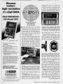
Discover
REPOh
REPORTS HIFl
_PORTS HIFl REPORTS HI.FI ht
cPORTS HIFl REPORTS HIFl REPO'
REPORTS HI Fl REPORTS HIFl REP()
REPORTS HIFl REPORTS HIFl REPOR1
Fl REPORTS HIFI REPORTS HIFl REPORT
today's
high - resolution
3'/2 -digit DMM HIFl REPORTS
rt1Fl
fS HIFl
l
.
-I
I
=1
cifically govern car -fi. A car stereo that
is claimed to have "50 watts of music
power" can actually have less power than
a 20 -watt unit. Hi -fi manufacturers are
required to rate amplifier output in watts per-channel RMS (Root Mean Square or
.707 of the peak power level; i.e. 100 watts
REPORTS HlF1 REPORTS H1FI REPORTS
REPORTS HIFl REPORTS HIFl REPOR'
REPORTS HIFl REPORTS HIFl REPORT
'I REPORTS HIFl REPORTS HIFI REP('
PORTS HIFl REPORTS HIFl REP('
"'PORTS HIFl REPORTS HIFl P'
''ORTS HI FI REPORTS N'
!.FI
B& K- PRECISION's
LCD
Model 2815
-
ylFI REPORT('
'
Put supersound in
your supercar
by Gordon Sell
Auto -Audio, Mo-Fi, Auto-Sound
and Car -Stereo are just a few of the
names given to what has become one of
the hottest things in electronics since the
transistor radio. All over the country people are turning their cars into mobile listening rooms with audio control panels
that make their dashboards look like a
747's instrument panel.
My own theory about the cause of this
boom in car stereo is based on this country's love of the automobile. With all the
environmental and energy problems this
love has been redirected from building
high performance, gas eating, air poluting,
hot rods towards improving a car as a
living environment. Your basic, gas stingy,
non- poluting car just doesn't have the
pizzazz of the supercars of yesteryear, so
people are giving their cars a new kind of
electronic pizzazz. That super, sound sysCar -Fi,
Model 2815
$150
0.01 ohm, 100nA, 100µV
resolution
0.1% DC accuracy
Shielded and protected to stay
accurate in rf fields
Fully overload protected on all
ranges
Auto -zero and auto -polarity
Alternating high -/low -power ohms
ranges for solid -state circuitry
measurements
50 watts is down to 17.5, and if you are
Available for immediate
delivery at your local
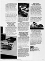
Installing a car stereo is a lot easier when
the manufacturer provides the correct
adapters. This Jensen R -420 AM /FM cassette
unit fits all standard cars. For more information about this $399.95 unit circle No. 44.
gKPRECISION
tern also has the advantage of making your
DYNASCANCORPORATION
6460 West Cortland Street
Chicago, Illinois 60635 312/889 -9087
In Canada Atlas Electronics. Ontario
Intl Sis Empire Exp 270 Newtown Rd Plainview. L
I
NY 11803
peak power* is equal to 70.7 watts RMS),
car -fi manufacturers are not.
So that 50 watts is now down to about
35 watts, but we've forgotten those magic
words "per channel." If a car stereo manufacturer doesn't specify watts -per -channel
then assume they mean total power-the
sum of the two channels. Well now our
The 6x9 is a standard auto speaker size
that will usually replace the stock speaker.
These Royal Sound RS -600s are two way
units that cost $125 per pair. Circle 49.
Compare the resolution offered by
the new B &K- PRECISION Model
2815 with any other DMM in its price
class. Its high resolution stands
alone. The 2815 also delivers 0.1%
DC and 0.3% AC accuracy. For
added convenience, a tilt stand is
built -in.
B &K- PRECISION distributor
Clarion has been promoting their mobile
rack -mounting components. These give an
installation a more permanent look. Racks
come with up to four wells either vertically
or horizontally. From $6.50. Circle 50.
average, tinny subcompact sound a lot
more sumptuous.
Avoiding the Pot Holes. Buying a car
stereo system today is a lot like buying a
component hi -fi back when it first became
popular. There are no industry standards
or federal trade commission rules that spe-
planning to feed four large speakers they
are going to be a bit hungry with only
83/4 watts per speaker RMS.
Most of the respectable companies don't
use this sort of rating although I've seen
one or two who succumbed to advertizedspec inflation. With some of the fly -bynight outfits you can safely take their
power figure and divide by four to get the
RMS per channel figure. Compare power
in terms of watts-per-channel RMS only.
Road Noise. The inside of an automobile
is probably the worst possible place short
of a machine shop to try to get good
sound. There is not enough room for a
large speaker so the low frequency response doesn't get much below 50 or so
Hz, and road and machinery noise blocks
out the high frequency music. On the road
you won't be able to appreciate a set-up
(Continued on page 14)
CINCLE 6 ON READER SERVICE COUPON
12
ELEMENTARY ELECTRONICS
/
November- December 1979
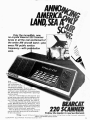
Only the incredible, new,
no- crystal Bearcat 220 Scanner
tunes in all the real excitement of
the entire AM aircraft band-plus
every FM public service
frequency -with pu button
ease.
Now.
Tune in all the
real excitement of
the wild blue yonder, at
the touch of a button.
The new, no- crystal Bearcat 220
Scanner searches and tunes in the entire aircraft band. Jets at 30,000 feet. All the tense tower
talk. Everything is pre -programmed in space-age
memory banks.
Only the 7-band Bearcat 220 Scanner also
brings home every public service frequency, too.
Pre -programmed Marine frequencies. Police action. Fire calls. Weather warnings. You name it.
The new Bearcat 220 has all the features and
quality Bearcat Scanners are famous for. Track
tuning. Decimal display readout. Automatic Search.
Selective Scan Display. Automatic squelch and
lockout. Priority. And much, much more.
After all, Bearcat invented Scanning. And we'll
stop at nothing to bring you all the excitement-.
of land, sea, and air.
ElectRi
BEARCAT
220 SCANNER
Follow the leader to real excitement.
Copyright 1979 Electra Company Division of Masco Corp. of ndiana 300 East County Line Road. Cumberland. Indiana 46229
CIRCLE 11 ON READER SERVICE COUPON
ELEMENTARY ELECTRONICS / November-December 1979
13
HI -FI REPORTS
that delivers a frequency response much
better than 50 to 13,000 Hz-of course
when you are parked that's another matter
'altogether. With vans and RVs (recreational vehicles) the sky's the limit as far
as finding space for those bigger speakers,
but sincë most of us are concerned with
equipping a standard sedan, that is all I
will refer to in this article.
If you think car stereo is just an AM/
FM radio in the dash then take another
look. A good car -fi unit is a full stereo
receiver with excellent electronic specifications, separate balance, treble and bass
controls. It can be connected to a number
of other components just like a home
stereo receiver.
In addition to receivers there are eight track and cassette tape decks, power ampli-
d
J
srfspin
a
99vCr
av\¡uickies
security
angler's
lake your
meter, do
JO Super
an to SWL's
band.
e IC
Projects
ing- Friendly
Sparkomatic's SR -3400 AM /FM cassette, indash unit has built-in clock for $300. Circle
Reader Service Number 45 for information.
a new version of
favorite using the
C logic technology
NOW your friends.
,
LE NOV. 8th, 1979
fiers, graphic equalizers, reverberation units
and time delay units. These components
can be mounted under the dash or in
add -on consoles. Choosing components is
I
even harder than picking a good auto receiver, so choosing a reliable manufacturer is even more important.
Another important consideration is
whether you intend to do the installation
yourself. This is not always as easy as it
looks especially on newer cars and cars
Three -way car speakers usually have the
tweeter and midrange inside the woofer
cone for compactness. These Jensen Triax
II's carry a retail price of $140. Circle 44.
with air conditioning. Before you go
shopping take a good, long look under
your dashboard. Can you get the old radio
out and a new one in without first getting
a degree ill mechanical engineering; if you
have stereo speakers will you be able to
replace them with more suitable ones; and
if you don't have two speakers, will you
be able to find a place for the new ones?
While you are under the dash take a look
at how the radio is supported. It might
help to make a rough sketch of the various
support straps and jot down the dimensions
of just about everything before you go
shopping. You can even take the radio
(Continued on page 16)
[ It15ERTI011 TOOL
36.40 Pm
C0105-SAFE
Unique new insertion tool. Also aligns bent out pins. A twist of the handle compresses
the pins to proper .600 inch spacing and
locks the IC into the tool. Then simply place
the tool on the socket and depress the
plunger for instant and accurate insertion.
Features heavy chrome plating throughout
for reliable static dissipation. Includes terminal lug for attachment of ground strap.
Mos.40
X795
EACH
INSERT I.C.
MINIMUM BILLING $25.00 ADD SHIPPING CHARGE $1.00
NEW YORK STATE RESIDENTS ADD APPLICABLE TAX
olc
OK MACHINE & TOOL CORPORATION
3455 CONNER ST., BRONX, N.Y. 10475 U.S.A.
TELEX 125091
14
CIRCLE 101 ON READER SERVICE COUPON
REMOVE INSERTER
"LOADED" P.C. BOARD
EWLU
2
e
1ND ELECTßIMCS
RAM
NEWTS
U.S.
Reg.
Pat.
Off.
PROGRESSIVE HOME
RADIO -T.V. COURSE
*
*
*
*
Now Includes
12 RECEIVERS
3 TRANSMITTERS
SQ. WAVE GENERATOR
* SIGNAL TRACER
*
**
*
*
*
AMPLIFIER
SIGNAL INJECTOR
CODE OSCILLATOR
No Knowledge of Radio Necessary
No
Additional Parts or Tools Needed
Solid State Circuits
Vacuum Tube Circuits
'Training Electronics Technicians Since 1946
FREE EXTRAS
YOU DON'T HAVE TO SPEND
SET OF
HUNDREDS OF DOLLARS FOR A RADIO COURSE
"Edu -Kit" offers you an outstanding PRACTICAL HOME RADIO COURSE
The
at a
rock -bottom price. Our Kit is designed to train Radio & Electronics Technicians, making
use of the most modern methods of home training. You will learn radio theory. construction practice and servicing. THIS IS A COMPLETE RADIO COURSE
EVERY DETAIL.
You will learn how to build radios, using regular schematics; how IN
to wire and solders
in a professional manner; how to service radios. You will work with
the standard type of
Punched metal chassis as well as the latest development of Printed Circuit
chassis.
You will learn the basic principles of radio. You will construct, study and
work with
RF and AF amplifiers and oscillators. detectors. rectifiers. test equipment.
will learn
and practice code, using the Progressive Code Oscillator. You will learnYou
and practice
trouble- shooting, using the Progressive Signal Tracer. Progressive Signal Injector,
Progressive Dynamic Radio & Electronics Tester, Sgaare Wave Generator and the accompanying instructional material.
You will receive training for the Novice, Technician and General Classes of F.C.C. Radio
Amateur Licenses. You will build Receiver, Transmitter, Square Wave Generator, Code
Oscillator, 'Signal Tracer and Signal Injector circuits, and learn how to operate them. You
will receive an excellent background for television, Hi -Fi and Electronics.
Absolutely no previous knowledge of radio or science is required. The "Edu -Kit" is
the product of many years of teaching and engineering experience. The "Edu-Kit"
provide you with a basic education in Electronics and Radio, worth many times the will
low
price you pay. The Signal Tracer alone is worth more than the price of the kit.
THE KIT FOR EVERYONE
You do not need the slightest background
In radio or science. Whether you are interested in Radio & Electronics because you
want an interesting hobby. a well paying
business or a job wìtb a future, you will find
the 'Edu -Kit" a worth -while investment.
Many thousands of individuals of all
ages and backgrounds have successfully
used the "Edu -Kit" in more than 79 countries of the world. The "Edu-Kit' has been
carefuliy designed. step by step, so that
you cannot make a mistake. The 'Edu -Kit'
allows you to teach yourself at your own
rate. No instructor is necessary.
PROGRESSIVE TEACHING METHOD
rogressive Radio "Edu -K t
is the foremost educational radio kit in the world,
e
and is universally accepted as the standard in the field of electronics training. The "EduKit" uses the modern educational principle of "Learn by Doing.' Therefore you construct.
learn schematics, study theory practice trouble shooting-all in a Closely integrated program designed to provide an easily- learned. thorough and interesting background in radid.
You begin by examining the various radio parts of the "Edu- Kit." You then learn the
function, theory and wiring of these parts. Then you build a simple radio. With this first
set you will enjoy listening to regular broadcast stations, learn theory. practice testing
and trouble-shooting. Then you build a more advanced radio, learn more advanced theory
and techniques. Gradually, in a progressive manner, and at your own rate. you will
find yourself constructing more acvanced multi -tube radio circuits. and doing work like B
professional Radio Technician.
Included in the "Edu -Kit" Course are Receiver, Transmitter, Code Oscillator, Signal
Tracer, Square Wave Generator anc Signal Injector Circuits. These are not unprofessional
"breadboard" experiments, but genuine radio circuits, constructed by means of professional
wiring and soldering on metal chassis, plus the new method of radio construction known
as "Printed Circuitry." These circuits operate on your regular AC or DC house curent.
THE "EDU -KIT" IS COMPLETE
will receive all parts
and instructions necessary to build twenty different radio and electronics circuits. each guaranteed to operate. Our Kits contain tubes. tube sockets. variable. electrolytic, mica. ceramic
and paper dielectric condensers, resistors, tie strips. hardware, tubing. punched metal chassis. Instruction
Manuals, hook -up wire, solder, selenium rectifiers, coils. volume controls, switches, solid state devices, etc.
You
-
In addition, you receive Printed Circuit materials, including Printed Circuit
special tube sockets, hardware and instructions. You also receive a usefui set of chassis.
tools,
professional electric soldering iroi, and a self -powered Dynamic Radio and Electronicsa
Tester. The "Edu -Kit" also includes Code Instructions and the Progressive Code Oscillator.
in addition to F.C.C. Radio Amateur License training. You will also receive lessons for
servicing with the Progressive Sign:.l Tracer and the Progressive
Signal
a High
Fidelity Guide and a Quiz Book. You receive Membership in Radio -TV Club,Injector,
Free Consultation Service, Certificate of Merit and Discount Privileges. You receive all parts, tools,
instructions, etc. Everything is yours to keep.
TOOLS
SOLDERING IRON
ELECTRONICS TESTER
PLIERS- CUTTERS
VALUABLE DISCOUNT CARD
CERTIFICATE OF MERIT
TESTER INSTRUCTION MANUAL
HIGH FIDELITY GUIDE
QUIZZES
TELEVISION BOOK
RADIO
TROUBLE -SHOOTING BOOK
MEMBERSHIP IN RADIO -TV CLUB:
FCC
CONSULTATION SERVICE
AMATEUR LICENSE TRAINING
PRINTED CIRCUITRY
L
SERVICING LESSONS
You
I
will learn trouble- shooting
and
Servicing in a progressive manner. You
will practice repairs on the sets that
You
will
learn
you construct.
symptoms
and causes of trouble in home. portable
will learn how to
Tracer. the
unique Signal Injector and the dynamic
Radio & Electronics Tester. While you
are learning in this practical way. you
will be able to do many a repair job for
your friends and neighbors, and charge
fees which will far exceed the price of
the "Edu- Kit.' Our Consultation Service
will help you with any technical Problem9 you may have.
and car radios. .You
use the professional Signal
FROM OUR MAIL BAG
Ben Valerio. P. O. Box 21, Magna.
Utah: "The Edu -Kits are wonderful. Here
I am sending you the questions and also
the answers for them. I have been in
Radio for the last seven years. but like
to work with Radio Kits. and like to
enbuild Radio Testing Equipment.
joyed every minute I worked with the
different kits: the Signal Tracer works
fine. Also like to let you know that
feel proud of becoming a member of your
Radio -TV Club.
Robert L. Shoff. 1534 Monroe Ave..
Huntington, W. Va.: "Thought I would
drop you a few lines to say that I received my Edu-Kit. and was really amazed
that such a bargain can be had at such
a low price. I have already started repairing radios and phonographs. My
friends were really surprised to see me
get into the swing of it so quickly. The
Trouble -shooting Tester that comes with
the Kit is really swell. and finds the
trouble. if there is any to be found."
1
SOLID STATE
Today an electronics technician or hobbyist rea knowledge of solid state. as well as vacuum
tube circuitry. The "E du-Kit" course teaches both.
You will baild vacuum tube. 150% solid state and
quires
combination ( "hybrid ") circuits.
Progressive "Edu- Kits" Inc., 1189 Broadway, Dept. 599 -DJ Hewlett, N.Y. 11557
PRINTED CIRCUITRY
At
now
increase in price, the
includes Printed Circuitry.
no
Please rush me free literature describing the Progressive
Radio -TV Course with Edu -Kits. No Salesman will call.
I
"Edu- Kit"
You build
Printed Circuit Signal Injector, a unique
servicing instrument that can detect many
Radio and TV troubles. This revolutionary
new technique of radio construction is now
becoming popular in commercial radio and
TV sets.
A Printed Circuit is a special insulated
chassis on which has been deposited a conducting material which takes the place of
wiring. The various parts are merely plugged
in and soldered to terminals.
Printed Circuitry is the basis of modern
Automation Electronics. A knowledge of this
subject is a necessity today for. anyone interested in Electronics.
1
a
NAME
I
ADDRESS
CITY & STATE
ZIP
PROGRESSIVE "EDU- KITS" INC.
1189 Broadway, Dept.
599 -DJ
Hewlett, N.Y. 11557
t
CIRCLE 18 ON READER SERVICE COUPON
ELEMENTARY ELECTRONICS /November -December 1979
15
HI -FI REPORTS
part way out just to
see how the new one
will have to be mounted.
Installation. Some units will install in
some cars in next to no time while others
will require a lot of time and effort. Any
reputable manufacturer includes or has
aa.ee.,Or.
ÿ
.P.
ì
t
;
i+
x
.:
_:
o
ìes
tt.er.
the jumbled audio environment of
In
a
car
an equalizer can make a real difference. This
Mitsubishi CV -23 is a booster /equalizer and
sells for $179.95. Circle service number 46.
available instructions and adapters to allow
installation in most American and imported cars. Some dealers may act dumb
when you ask about adapter kits if they
are not included with the radio. Just don't
take no for an antswer, some dealers will
tell you nothing is available when they are
just too lazy to order, or they are trying
to drum up business for their own installer.
If a dealer is uncooperative, just go to
another dealer.
Try to do a quality installation job.
There is nothing more unattractive than a
car with wires running here and there, and
brackets held in place with duct tape. Feéd
wires under the rugs and tie them up under
the dashboards so they don't hang down.
To get wires from the front of the car
to the back, detach the trim on the bottom
of the door frame so that you can get
under the edge of the rubber floor pan
covering. Slip wires under the covering
and replace the trim. You'll be the only
one who knows they are there.
Install rear speakers unobtrusively if
you live in a high car theft area. Having
Little Giant Trans Systems Tuner Kit S122.50
Wired E1 Tested
$144.50
"Little Giant" 2500X -2, for an "engineered performance'
Designed and engineered after "Apollo"
Trans Systems Tuner and Adaptations of the Lew McCoy Transmatch, with power handling at the KW plus level!
Kit includes:
I
2
I
I
heavy
apollo products
6
10- 15- 20-40 -80 meters
200 pfd wide -spaced variable
with Isolantite Insulation rated 3.000
volts
I
200 pfd dual section parallel
condenser Isolantited
finger -grip pointer knobs 2"
diam. white indented
pvc Insulated shaft couplings /4
to v.
3 SO -239 coax chassis connectors.
Tunes 52 ohm or 52- 300.600 or
random wires
for
inductance
pvc stand -offs. 4 for condensers
2 for inductance
HD switch for band catching 10
thru 80 meter coverage
I pkg 12 -gauge tinned round wire.
Cabinet included -Apollo "Shadow
Boxes" M Kit Includes schematic.
Recommend parts layout.
INFO NOTE 377 OHM and
OHM "Open wire spaced ladder line"
air dialectrlc.
84 x wire diam
53 x wire diem.
info only -not supplied
and
I
600
.
.
245, Vaughnsvllle, Ohio 45893
419- 646 -3495
146811°x
big, bulky rear shelf speakers is like putting a sign up that says "this car has an
expensive stereo." Try to make all installations look like they were done when the
car was built and you'll be much less likery
to be ripped off.
It is almost impossible to make under-
Sanyo's extensive line of auto -audio products includes this sharp looking 7 -band
graphic equalizer. Costs: $70. Circle 80.
dash units look standard but you can make
them as descrete as possible. Put them as
far under the dash as you can Without
putting them out of reach. If you are very
good with tools you might even find a
blank spot in the dash and mount it there,
but don't do this unless you really know
what you are doing. If you want to give
a gadget a permanent in -dash mount you
have to decide what you will do when you
sell the car. Either sell the gadget with the
car or expect a large drop in value because of the empty hole in the dash. If
you change cars often you might be better
off sticking to under -dash mounts for your
specialty gear. Power amps and devices
with permanently set controls can go way
back tinder the dash, under the seat or
even in the trunk.
What's Available. The auto-sound marketplace is almost limitless. Just about anything short of a turntable is available in
one form or another for car installation.
The manufacturers include most of the big
Subsidiary "Little Giant Antenna Labs
CIRCLE 25 ON READER SERVICE COUPON
THE MAGAZINE OF FAMILY OUTDOOR RECREATION
Go backpacking ... go trailering ... go fishing ... go adventuring ... go anything ... but don't go outdoors again without
CAMPING JOURNAL.
itwrorer.ran
It's the No.
1
or
...KT ourr000rt rourwooarr
passport to America's favorite recreation.
Discover for yourself new and exciting places that get you away
from day-to -day routine.
CL 1.".4"."6'
trod.Coror
b-
OY.w16.owq,
CAMPING JOURNAL is crammed like an overstuffed backpack with
ideas for more camping fun. What to do. Where to find it. What kind
of gear to get and how to keep it working right.
nRnu
JOURNG'L
great magazine. Your kind. When
you're reading CAMPING JOURNAL
you soon realize we're staffed with
stone -hard camping fanatics.
A
for yourself how much we can
add to your favorite leisure -time
See
activity!
Please avow a to e weeks for
delivery of your first copy.
CAMPING JOURNAL, Box 2620, Greenwich CT 06835
O Send me 7 issues for ONLY $5.97, regularly
$7.95 by subscription.
n Bill me $5.97
I enclose $5.97
Outside U.S.A. and possessions, $6.97
Name
Address
City
.
_
átate- --
_
Zip
Expand the size of your car with Fujitsu
Ten's RV- 130EX-1 graphic time delay. This
$180 unit also has a reverbe. Circle 47.
names from the audio industry, some CB
manufacturers who are taking advantage
of their long experience with auto electronics and a couple of newcomers who
are making their name in auto sound.
On these pages I've shown a small sample of what's available. We have not had
a chance to test all of these in the lab,
but they all come from well respected
companies so you can be reasonably sure
of the quality. If you want more information about these company's product lines
then circle the appropriate Reader Service
Numbers on the card elsewhere in this
issue. Fill out the card and send it in.
We'll tell the manufacturers to send you
their latest brochures.
CIRCLE 30 ON READER SERVICE COUPON
16
ELEMENTARY ELECTRONICS
' November -December
1979
on meteoric unization and sporadic -E cloud
movements. The Confidential Frequency.
List is published by Gilfer Associates, Inc.,
P.O. Box 239, 52 Park Avenue, Park
Ridge, NJ 07656.
Solar Electricity Guide. Flow to put
solar electricity to work for you is explained in a new manual, The Solarex
Z -80 Brain Waves. The Zilog Model
Z-80 represents a microprocessor that is
how -to guide on
solar energy.
A
extremely sophisticated and attractive to
many computer users. Now you can pick
inside the Z -80's brain by reading Z -80
Microcomputer Handbook by William Bar-
Soft cover
140 pages
$6.50
handy guide to
the Zilog
microcomputer.
A
CIRCLE 54
ON READER SERVICE
Soft cover
304 pages
$8.95
CIRCLE 56
ON READER SERVICE
COUPON
den, Jr. Organized into three sections, the
first section concentrates on hardware; the
second on software; and the third on
microcomputers built around the Z -80.
This handbook will provide the current
user and the prospective user with essential
infomation on the technology of the Z -80
Published by Howard W. Sams & Co., Inc.,
4300 West 62nd St., Indianapolis, IN
46206.
Tuning In. Thanks to author Oliver P.
Ferrel, the Fourth Edition of Confidential
Frequency List identifies over 6000 stations
operating betwen 4000 and 25,590 kHz in
what is broadly termed the "Utility" stations. This compilation in a new convenient format is a "hot dog" text for SWLs
CONFIDENTIAL
Firsthand "Utility"
station news.
Soft cover
104 pages
$6.95
CIRCLE 57
ON READER SERVICE
COUPON
A
who specialized in tuning in Military,
Coast Guard, Maritime, Aeronautical Mobile, Fixed, VOLMET Time, RCMP, etc.
stations. The authenticity of the text
springs from the author's lifetime experience. Perry, as his friends call him, wrote
numerous articles on FM and VHF propagation in the late 1930's. After service in
WWII, Perry served as chief editor of CQ,
Stereo Review and Popular Electronics.
He has published original research papers
COUPON
Guide to Solar Electricity. Designed for
everyone from the amateur solar enthusiast to the professional energy expert, the
new guide provides a full description of
the do's and don'ts of converting the solar
system's most abundant energy resource,
sunlight, into useable electrical energy by
means of solar cells. The pages of this
resource book are filled with charts, graphs,
drawings and diagrams of solar cell applications. Photographs and text provide full
description of projects. These range from
solar electric demonstration set-ups for
schools to solar -powered toys and wrist
watches, solar -powered fans and recreational equipment on up to large scale applications, such as a massive installation
for total energy requirements of Mississippi County Community College, Blytheville, Ark. Parallel and series connections
of solar cells with capacitors, current limiters, storage batteries and voltage multipliers
are diagrammed and explained. The guide
book may be obtained by writing to Ed
Roberton, Solarex Corp., CPD -Dept. L100,
1335 Piccard Drive, Rockville, MD 20850.
Add 55 cents to the purchase price for
shipping and handling.
Bell Started lt. Nowadays telephones
are much more than just another spaceage communications gadget. Thanks to
20th century technology, phones have
hundreds of new capabilities: one can add
an accessory or two and it will dial a number automatically, or let one hear and see
a früend, or sound an alarm, or divert incoming calls to another number, or handle mathematical calculations, or even
accesss to a computer. At last here's a
book by Van Waterford entitled All About
(Continued on page 84)
%Chock -full of independent lab test re-
ports...
on receivers, tuners, pre -
amps,
cassette
decks,
turntables, headphones
and phono pickups!
NOW...
ON YOUR
IWe report on what
our independent
testing laboratory
NEWSSTAND!
found out when it
tested the new metal
tapes!
hífístereo
%We tell you all
about receiver features that are available to you and what
they do!
WIWe focus in on
speaker design concepts- you'll learn
everything you need
to know to make a
wise buying decision!
AND MORE, MUCH
MORE-DON'T MISS IT!
On Sale
Thursday October 251
ELEMENTARY ELECTRONICS / November- December 1979
II'//
A DAVIS PUBLICATION
17
Microcomputers are here!
Get in on the ground floor with
NRI's new "at home" training
in computer technology.
Only NRI Gives You "Hands -on" Experience as You Build Your Own
Designed- for-learning Microcomputer
0106 KAOLIN ACS *AINYSORTCN
MO
WW1
0800
COMA
CACO
WE REPO
OM
*
PRESSED?
+ND: TRYACARI
MXJ DA OS* DATA SWTTC4
0006 COYA
0700 OEC ROOF
0000 SSA WAIT of
MOW IDA AOS
000 CAMA
1100
EEOREAOF
FOR A LEOS
1300 STAA LEDS
1400 RTS
«R 1I3I
1600 REAM LOA A OS «FUNC1
ISA
18
ELEMENTARY ELECTRONICS
/
mow`
November- December 1979
The microprocessor, that amazing little chip which shrinks electronic
circuitry to microscopic size, has
changed the world of the computer
with dramatic speed. Now, big performance computers are here in
compact sizes...priced to make them
practical for thousands of medium and
small businesses, even homeowners
and hobbyists.
Microcomputers are already
being put to work on jobs like inventory control, payrolls, cost analysis, billing, and more. In homes, they're able
to handle budgets and tax records,
control environmental systems, index
recipes, even play sophisticated games.
And hobbyists across the country are
expanding the state of the art while
developing their own programs.
Become a Part of This
Incredible World ...
Learn at Home
in Your Spare Time
NRI can give you the background you need to get into this booming new field. Microcomputers require
a new discipline, a broader viewpoint...
the ability to think in both hardware and software terms. And NRI's
new course in computer technology
is geared to bridge the gap.
You get a firm foundation of digital
theory while you get practical,
Other Courses
in Today's Electronics
"hands -on" experience working with
the NRI Discovery Lab ®, assembling
test instruments you keep, and even
building your own fully functional
microcomputer.
Best of all, you do it at your own
convenience. You learn at home with
clearly written, "bite- size" lessons that
carry you through the course in logical
progression. There's no need to go to
night school or quit your job...you
progress at the pace that's most colnfortable to you, backed by your personal NRI instructor and individual
counseling whenever you want it.
Assemble an Advanced
Microcomputer with
Exclusive Designed -forLearning Features
Only NRI trains you with a microcomputer that's specifically designed
to teach you important principles as
you build it. This state -of-the -art unit
performs every function of comparable
commercial units, has capabilities well
beyond many. But each step of construction provides specific training,
reinforces theory to make it come
alive. And once you've finished,
your microcomputer is ready to go
to work for you. Or you can even sell
it commercially.
You also assemble professional
test instruments for use in your training. You get your own CMOS digital
frequency counter and transistorized
volt-ohm meter to keep and use in
diagnosing problems and servicing
computers. Tbgether with up-to -theminute lessons and NRI's 60 -plus years
of home study experience, you get the
most in training and value.
ELEMENTARY ELECTRONICS, November -December 1979
Even the servicing of home
entertainment equipment has taken
quantum jumps forward. NRI keeps
you right up with the latest, with training in stereo, video tape and disc
players, and the latest TVs. You even
build your own 25" diagonal color TV,
the only one complete with built-in
digital clock, varactor tuning, and
computer control that lets you program
an entire evening's entertainment. In
our complete communications course,
you learn to service two -way radio,
microwave transmitters, radar, AM and
FM transmitters, CB radio, paging
equipment, and more. And you build
your own 2 -meter transceiver or 40channel CB while you learn.
Free 100 -Page Catalog
No Salesman Will Call
Send the postage -paid card
today for your personal copy of the NRI
electronics course catalog. It shows all
the equipment, training kits, and
complete lesson plans for these and
many other courses. There's no obligation of any kind and no salesman will
ever bother you. Find out how you can
learn new skills, keep up with technology, advance your future with training
for new opportunities. Get in on the
ground floor now! If card has been
removed, write to:
NR
NRI Schools
McGraw-Hill Continuing
Education Center
.,1 Ï
3939 Wisconsin Ave.
Washington, D.C. 20016
ll
I
21
Why settle
for
$75
worth of
performance
from your
ox central
reporting
A
$300 scanning
world of SWL info!
BY DON JENSEN
YOU READ THIS, the long awaited
World Administrative Radio Conference (WARC) of the International Telecommunications Union is underway in
Geneva, Switzerland.
At WARC -79, for ten weeks this fall,
representatives of the 154 nations which
are members of the ITU have been working on the frequency allocation ground
rules that will govern broadcasting -and
especially shortwave -channels for the rest
of the century.
The work of the conference is important.
It is estimated that there are some 900
million radio receivers in the world today;
300 million of them capable of tuning the
shortwave frequencies. Also, according to
estimates, on any given day around the
globe, up to 200 million persons listen to
a shortwave radio broadcast.
The importance of the conference's
work was highlighted earlier this year by
John A. Gronouski, chairman of the U.S.
Board for International Broadcasting, in
an address to the North Atlantic Treaty
Organization (NATO) Cultural Affairs
Committee.
Viable Medium. "Shortwave radio appears to be the only viable medium for international broadcasting in the foreseeable
future," Gronouski said.
"Shortwave broadcasting is not the exclusive domain of the more powerful
industrialized nations. It is the only
practical information medium at present
through which the voice of the smaller,
less affluent country can be heard, and can
reply to the major powers. Installations
are relatively inexpensive, within the
means of most of the developing nations."
Gronouski went on to note that the
AS
Mobile or base
,
Increase effective
reception up to four times
with a professional A/S
monitor antenna. Our
catalog lists 12
models, to answer
any need.
It's free.
the antenna
specialists co.
e
s,r Pa. m Que.,/
member of The Allen Group Inc.
12435 Euclid Ave Cleveland. Ohio 44106
a
CIRCLE 19 ON READER SERVICE COUPON
GILF
"NORTH
AMERICA'S
SHORTWAVE
MAIL ORDER
PLACE"
111)
One -Stop
Armchair Shopping
For All SWL Needs
* Receivers-Drake, Grundig,
Panasonic. Sony, Yaesu- special
mods for better performance *Digital
Frequency Readouts *Receiving Antennas
*Antenna Tuners *Frequency Calibrators
*Clocks *Logs *FM or TV Guides *OSL Albums
*AM Pattern Maps *ITU Publications *OSL Address
Books *All SWL Accessories *All SWL Books
Just Released
1979 Edition
CONFIDENTIAL
FREQUENCY
LIST
104 page book identifies
5000 special HF stations
(SSB, CW, FAX) from 4
to 26 MHz.
$6.95 ppd.
FREE SWL CATALOG
GILFER SHORTWAVE
Dept.
22
Ell
DX GLOSSARY
DXing= Distant station; the hobby of
listening to distant or hard -to -hear
stations.
DX,
GMT = Greenwich
Mean Time, a universal time reference equivalent to
EST +5 hours, CST +6 hours, MST +7
hours or PST +8 hours.
kHz = kilohertz, a unit of frequency
measurement equal to 1000 cycles
per second, formerly expressed as
kilocycles per second, kc /s.
MHz = Megahertz, unit of frequency
measurement equal to 1000 kHz.
SW, SWL, SWLing =short wave, shortwave listener, hobby of shortwave listening.
number of shortwave transmitters in use
jumped from 300 in 1950 to 1,500 today.
The amount of broadcasting has increased
five times since the end of World War II.
"Most shortwave frequencies are now
being used by double (and during preferential broadcasting hours), three and four
times the number of transmitters recommended as a reasonable norm by the ITU."
The former ambassador told the NATO
delegates that at the last WARC conference, in 1959, the technologically advanced countries of the West had a voting
edge. At WARC -79, however, the voting
clout is within the smaller Third World
nations. Countries such as Togo and Fiji
have one vote each, just as the United
States and the Soviet Union do. But there
are many of these developing countries,
and as Gronouski pointed out, they are
seeking a "share of the pie."
Gronouski proposed to the NATO delegates that the more technologically advanced nations demonstrate leadership at
the Geneva conference, that they propose,
in effect, a larger "pie," a doubling of the
shortwave broadcasting frequencies. Also,
he urged a recognition of the desires and
goals of the Third World majority for a
greater share of the shortwave frequencies.
Ambassador Gronouski spoke to the
NATO committee delegates in February.
Several months later the United States
proposals for the WARC -79 meeting were
finalized. Not surprisingly they reflected
what Gronouski had suggested.
Happily for just about everyone- including SWLs- earlier "talking" positions
which would have gobbled up some of
the low SW frequency Tropical Bands
(the special territory of the Third World
countries) by the International Broadcasting "biggies" were forgotten. In fact,
the U.S. final position proposed an expansion, not a contraction, of the Tropical
Bands for domestic broadcasting use, especially in the developing nations. If
adopted as proposed by the U.S. delegates,
the Tropical Bands in the lower end of the
shortwave spectrum would grow by some
300 kilohertz, and there would be new
Tropical Bands, from which so-called
International Broadcasting would be excluded, as high as 14 MHz.
The United States, of course, is primarily interested in increasing the shortwave bands for International Broadcasting.
The proposal would expand the existing
frequencies used by the major foreign
service broadcasters by about 1,500 kilohertz of band space, between 5,800 and
22,000 kHz. And the American proposal
would create two completely new bands.
one in the upper 13 MHz range, the other
just below 20 MHz.
The U.S. also proposed transmitter
power limitations of 50 kilowatts for
domestic shortwave operations and 250
kW for external services, with a grandfather clause for those stations already exceeding those powers.
Of course, no one expects that the U.S.
.proposals will emerge unscathed from
WARC-79. The Soviet Union is on record
(Continued on page 84)
Box 239, Park Ridge NJ 07656
CIRCLE 20 ON READER SERVICE COUPON
ELEMENTARY ELECTRONICS / November -December 1979
SOU ASKED FOR IT
YOU GOT IT
DSI QUIK -KITS
50 HZ
- 550 MHZ COUNTER KIT
95% ASSEMBLED
100% TESTED
Performance You Can Count On
FREQUENCY COUNTER APPLICATION:
-
-
Two Way Radio
CB
Audio Amplifier & Receiver Repair
Computer Maintenance & Construction
A Must for TV
PLL & VTR Repair
Ham Radio
-
$9995
includes built-in
P -e -Amp & Prescale
MODEL 3550K
DSI OFFERS THE BEST OF TWO WORLDS .. .
An unprecedented DSI VALJE ... in a high quality, LSI Design,
50 HZ to 550 MHZ frequency counter kit. Arid, because it's
a DSI innovation, you know it obsoletes all compe-itive
makes, both in price & performance.
With 95% of the assembly completed by DSI, you are only
one hour away from solving all of those difficult bench
problems, from adjusting E0 HZ clock -time bases to setting
the frequency of a 468 MHZ Mobile Radio.
(800- 542 -6253)
(800- 854 -2049)
Model
Price
3700
Accuracy
Over
Temperature
Frequency
Range
50Hz
$269.95
-
700MHz
Proportional
.2
3600A
$199.95
3550W
-
600MHz
50Hz
-
550MHz
$149.95
3550K
1
50Hz
$
HZ Resolution to 55 MHZ
3550K Kit
T -101 Ant.
AC -9 AC Adp
Shipping, Handling, Ins.
TERMS:
MC
PPM
Oven
0° - 40 °C
Oven
5
PPM
1
PPM
17° - 37 °C
TCXO
10 HZ
$99.95
3.95
7.95
.. 10.00
- VISA - - Check - M.O -COD it
AE
Every 3550 QUIK -KIT® PC board is
factory assem hled and tested before shipment.
The problems of bad LED's, IC's, and
No
Capacitors are a thing of the past.
manufacturer except DSI offers a 550 MHZ
frequency counter with ... 8 digits, .5 in. LED's,
TCXO, HZ resolution and a one year warranty
We do not
on parts for under $100.00.
know how long we can hold this low, low price.
65° - 85 °F
Number
@
@
@
146MHz
220MHz
450MHz
of
Readouts
1OMV
1CMV
5OMV
8
Size
of
Readouts
.5
Inch
10MV
1C+MV
50MV
8
.5
Inch
25MV
2EMV
75MV
8
.5
Inch
Resolution to 550 MHZ
E55
CZ
.1
and
VISA
I
1
Power
Requirements
115
8.2 -
115
8.2 -
115
8.2
VAC
VAC
or
14.5VDC
VAC
Sec. Gate Time
"W
x 6 "0
21/4"H x 8 "W x 5 "D
2,'é
"H
x 8
"W
x 5 "D
Auto Zero Blanking
3550W Wired
DSI INSTRUMENTS, INC.
7924 Ronson Road, Dept. G
San Diego, Califcrnia 92111
Shipping (incl.)
AC -9 (incl.)
U.S. Funds. Orders outside of USA and Canada. please add $20.00 additional to cove: air shipment.
3 "H x 8
or
14.5VDC
T -101 (incl.)
CIRCLE 105 ON READER SERVICE COUPON
or
14.5VDC
Size
$149.95
NC
NC
NC
California residentsadd 6%Sales Tax.
-
FOIflE
newscan
EXPERIMENTEI
INTERNATIONAL
Electronics in the News!
CRYSTALS and KITS
OF -1
OSCILLATOR
$4«
The OF -1 oscillator is a
resistor /capacitor circuit
providing oscillation over a range of frequencies by inserting the desired crystal, 2 to 22
MHz, OF-1 LO, Cat. No. 035108. 18 to 60
MHz, OF-1 HI, Cat. No. 035109. Specify
when ordering.
MXX -1 Transistor RF Mixer
3 to 20 MHz, Cat. No 035105
20 to 170 MHz. Cat. No. 035106...
SAX -1 Transistor RF Amp
3 to 20 MHz, Cat. No. 035102
20 to 170 MHz, Cat. No. 035103
BAX -1 Broadband Amp
20 Hz to 150 MHz, Cat. No. 035107.
$5.80 ea.
$5.80 ea.
$6 06 ea.
Microcomputer Marathon
After a demanding 81/2-day marathon, a
group of high school students in the southern Texas city of San Antonio is claiming
a new world's record. However, if the
students of Holy Cross High School are
to be recognized for their efforts, a new
category will be needed in the record
books.
The famous Guinness Book of World
Records, which lists such exotic feats as
marathon flagpole sitting, breath holding
and rope jumping, as of yet has no category for computer marathons. But the 311
.02% Calibration Tolerance
EXPERIMENTER
CRYSTALS
(HC 6/U Holder)
$522
ea.
Specifications
Cat. No.
031300
031310
3 to 20 MHz -For use in
OF-1L OSC Specify when ordering.
20 to 60 MHz -For use in OF-1H OSC
Specify when ordering.
Enclose payment with order (no C.O.D.). Shipping
and postage (inside U.S.. Canada and Mexico only)
will be prepaid by International
Prices quoted for U.S.. Canada and Mexico
orders only Orders for shipment to other
countries will be quoted on request.
Price subject to change. Address orders to
M.S. Dept., P.O. Box 32497
Oklahoma City, Oklahoma 73132
WRITE FOR BROCHURE
International Crystal Mfg. Co., Inc.
10 North Lee.Oklahoma City, Oklahoma 73102
CIRCLE 22 ON READER SERVICE COUPON
NOWIFOR
McGEE'S
BIG SPEAKER CATALOG
1001 BARGAINS IN
SPEAKERS
-
PARTS
COMPONENTS
Tape
-TUBES
-
-
HIGH FIDELITY
RECORD CHANGERS
Recorders- Kits -Everything
in
Electronics
1901 McGee Street, Kansas City, Missouri 64108
Give money.
Even more, give
understanding.
United
Cerebral Palsy
24
Approximately 300 students at San
Antonio's Holy Cross High School recently
took part in what they believe was a
record -setting
eight -day, 24- hour -a -day
computer training marathon. Using TRS-80
Microcomputer Systems from Radio Shack,
the students learned the basics of computer operation and programming.
Holy Cross students who took part in an
eight -day, around -the -clock computer training session during January, 1979 believe
that their accomplishment deserves a mention in future record books.
Instructor Dennis Doose, chairman of
the Holy Cross science department, agrees.
It was Doose who suggested the computer
training marathon after students began
staying after class -voluntarily -to use the
school's TRS -80 Microcomputer System.
"So what better way to get as many
students as possible exposed to computers?" Doose asked.
The department chairman then explained
that Radio Shack, manufacturer of the
TRS -80, agreed to loan the school 22 additional microcomputers for the event.
The response was "fantastic," according
to Doose, who added that students were
actually lined up at the door when the
computer training marathon began on Friday, January 12. About 206 hours later,
311 Holy Cross students had logged time
on the computers. Although most had
never used a computer before, "everything
went well," according to instructor Doose.
The students took turns, and at least
-
two computers usually more were in
constant use throughout the marathon,
which ended at 9 A.M. on Sunday, January 21. More experienced students even
brought sleeping bags so 24 -hour supervision would be available for computer
novices. As a result of the marathon, 72
students completed the TRS -80 computer
programming course.
One thing about records! They are made
to be broken. I wonder if the people at
Apple, Heath or OSI will take up the
challenge.
Pacemaker Temperature Monitor
The backstage collapse of 74- year -old
movie star Pat O'Brien, as well as the
incident of the Arlington, Texas fan revived with mouth-to -mouth resuscitation
by Texas Rangers pitcher "Doc" Medich,
focused national attention on a vital but
vulnerable component of pacemakers: the
batteries.
The self -generating lithium oxide batteries used in pacemakers have a life of
10 -15 years. That life can be considerably
shortened, however, by exposure to tern peratures in excess of 140 °F. Pacemaker
manufacturers, therefore, take every precaution to protect their product during
shipment. One highly- effective and widely used method of protecting against high
temperatures is the Tempilabel° temperature indicating monitor.
Tempilabels have spots that turn black
at designated temperatures (they are available with temperature ratings of 100 °F to
600 °F). If a shipment arrives and the
spots have turned black, it is certain that
it has been exposed to temperatures at
least as high as the Tempilabel's rated
temperature. If the spots have not turned
black, it is equally certain that the shipment has not been exposed to that tem-
perature.
Cardiac Pacemakers, Inc., of St. Paul,
MN, places a Tempilabel in the shipping
carton. The label contains four sequential
photo of a pacemaker shows the
Tempilabel °, a temperature indicatingmonitor, as an integral part of the unit.
This
Diagram shows the high temperature indicator enlarged 4 times.
temperature sensitive spots that turn black
when temperatures of 100 °F, 125 °F,
150 °F, and 175 °F are reached. American
Pacemakers, of Woburn, MA, also places
the Tempilabels in the shipping cartons.
American Technology, of Northridge, CA,
places a Tempilabel directly on each pacemaker. An epoxy coating covers the entire
surface of the pacemaker, including the
Tempilabel, and eliminates any problem
of rejection of the Tempilabel by the
patient's body.
ELEMENTARY ELECTRONICS ! November- December 1979
Heathkit gift ideas make this the merriest Christmas ever
BIG,NEW
Heath kit
CHRISTMAS
Gíant-acnen Pr0atíon Color
Television W9a 102.102
State-of -the -art PMJrM
Stereo Receiver - legs 74
Antenna Tutor Mae ideal
Amateur R4dlo 9a One 22
Digital Engin Analyzer for
bear turro-upe pegs 12
Trigonometry Sir.1»etrucbon
Program aes page 97
VMF Dust Wattmeer for the
-
CATALOG
-
-
a
Filled with all the newest Heath
Electronic Kits -nearly 400
beautiful gift ideas for home,
work or pleasure, all in moneysaving kit form.
-
shark- page 20
Darkroom Timer t;»rtect
for he photo butt --page 77
Ykelnyback Teeter for the
TV do- 6- yourseltr
page 61
The erhoIe family sit *may
the Thomas 0rgar
page t2
RP Speech Clipper Mr the
Radio Amateur
roe Page
Ntph-vhoe Pinbatt 2pya for26
the whoa lamie
Page 104
Nam Radio
-
-
New Heathkit Screen Star Projection TV
with big 6' diagonal screen and one of the
sharpest, clearest projectión pictures ever
achieved.
FREE -
Get tae Rtemote
Control
with your purchase
of e GR
62000 or G16- 205120Olor-2061,
TV1
New AR -1650 Stereo Receiver with big
power and many luxury features that let you
hear your music just the way you like.
New Pinball Game by Brunswick' puts pinball excitement right in your own home. Full
size, high- action scoring field.
New Dual VHF Wattmeter for Hams reads
forward and reflected power between 50
and 175 MHz. One of many great gifts for
your Ham.
HEATItKIT
pap
New Portable Engine Analyzer with digital
accuracy, inductive pick -up and multiple
functions.
'^
ORDER
xe,at,raet
CATALOG
^aemakeG
we,
NO. gq7
===Fk rtf De11P eGF't
New Educational Programs make it easy
to teach yourself electronics, practical math.
or computer-related subjects.
Send
MAIL
1
1
for yours today!
Heathkit
Please send me my FREE Heathkit Catalog.
am not currently receiving catalogs.
1
>w
FREE
I
1
tut
Heath Company, Dept.139.590
Benton Harbor. Michigan 49022
Name
Address
1
coupon is missing, write: Heath Co.,
Dept. 139 -590, Benton Harbor, MI 49022.
If
1
Heathkit Products are displayed, sold and serviced
coast -to -coast at Heathkit Electronic Centers
1
(Units of Schlumberger Products Corporation).
1
1
See the white pages in your phone book.
City
State
CL -718
Zip
L
CIRCLE
1
J
ON READER SERVICE COUPON
ELEMENTARY ELECTRONICS / November -December 1979
25
The"mobile moonraker" by Avanti
OUTPERFORM
THEM
ALL...
Avanti engineered to transmit further
give clearest reception!! Low
S.W.R. across 40 channels!
l-
(Continued from page 10)
benches, or lowcost permanent desk supports for SW shacks
and home computer labs. The Professional Model is designed
for use as a construction bench, as legged supports or as saw
horses. its 27 -inch height gives the craftsman proper working
leverage for hand and power tools. The Utility Model is made
for supporting table- height tops, counters, desks or drawing
Non -magnetic
Tapered whip culs
srgn,
HEY, LOOK ME OVER
chrome plated
lutte:''
brass
safeguards
antenna tuning!
Hermetically
sealed. high
strength. A.B.S.
Outperforms all top,
center, or base
loaded antennas
tested including
K -40, A/S, Firestik,
Hustler and Hy-Gain.
pertormance!
Solid copper
oil windings
delivers all the
-
power your
radio can
transmit
Silver plated
connector
mount
-
IOw
resistance
consistent
tent
performance
cor,osion srae!
-
WE GUARANTEE IT!
..0.. ring seal
prevents
and
woisture
ater leakage!
Get the facts. See
your Avanti dealer or
send 50.$ for catalog.
( strand
CIRCLE 41 ON READER
SERVICE COUPON
housing
protects against
moisture and
temperature and
assures
constant high
Heavy. duty 112'
-
mount
deeply grooved
no strip
threads
can't
pull loose.
Available with GIANT MOON
MAGNET. Improves reception
lowers SWR
in -line
connector.
antennas )
-
surfaces. While it can easily be used as a bench support or saw
horse, its 30 -inch height matches most table and counter
measurements and its 30 -inch width fits through standard
door openings. Stable-Mates models will support tested
weights in excess of 700 pounds. The Professional Model
weighs 10 pounds and the Utility Model weighs 8 pounds.
Both models sell for $25.00 each. Prices are F.O.B. To order,
address all correspondence to: Basic Materials, Inc., P.O.
Box 415, Richmond, VA 23203.
-
AVANTI RESEARCH and DEVELOPMENT. INC.
340 Stewart Avenue. Addison. IL 60101
1312) 626.9350
IN CANADA Lenbrook Industries. 1145 Bellamy Scarborough, Ontario MIN IH5
200 kHz To 30 MHz in 30 Easy Steps
R -1000 Communications Receiver, which provides
continuous frequency coverage from 200 kHz to 30 MHz in
30 bands, each 1 MHz wide, has been introduced by Trio/
Kenwood Communications, Inc. Frequencies are read easily
on an accurate, five -digit fluorescent -tube display, backed up
by an illuminated analog dial. The digital display also functions with a built -in quartz digital clock and an ON /OFF timer,
which continue to operate even when the receiver is turned off.
The model
SUBSCRIBE TODAY TO
ISAAC ASIMOV'S
Science Fiction Magazine
Now monthly!
To: ISAAC ASIMOV'S SF MAGAZINE
Box 1855 GPO, NYC, NY 10001
Enclosed is $7.50 for 6 issues (outside U.S.A. & poss.
$8.50).
I enclose $15.00 for 12 issues (1 yr.).
I prefer to use my MASTER CHARGE or VISA credit card
-however, only these longer terms are available:
1 yr. (12 iss.) $15.00
2 yrs. (24 iss.) $29.00
Credit Card No
Expiration date
Signature
Name
Address
City
State
Please allow
26
6
to
8
weeks for delivery of first issue.
H9J028
CIRCLE 52 ON READER SERVICE COUPON
An up- conversion PLL circuit and wideband RF circuits provide
exceptional receiver performance and easy operation. Simply
switch to the appropriate band and quickly tune to the desired
frequency while observing the digital display-no need for
bandspread, preselector, or antenna tuning control adjustment.
Operating modes include AM (wide and narrow), SSB (USB)
and (LSB), and CW. Three IF filters are built -in -one for SSB
and CW (2.7 kHz), one for AM narrow (6 kHz), and one for
AM wide (12 kHz).
On an easy-access sloping rear panel, are mounted the antenna terminals, ground-wire terminal, external- speaker jack
(4 -16 ohms), remote connector (for timer-activated start/
stop remote control of a recorder or other equipment, and for
receiver muting), AC power, fuse holder, and operating -voltage
selector (100/110/220/240 VAC). The R -1000 is available
through your local Trio /Kenwood dealer. For more information on the R -1000, contact Trio /Kenwood Communications,
Inc., 1111 W. Walnut St., Compton, CA 90220, or circle number 52 on the reader service coupon.
ELEMENTARY ELECTRONICS / November-December 1979
Palm -Size DMM
The new hand-held LCD display precision
digital multimeter, designed primarily
for field use, is a full- function, 31/2 digit
DMM with 0.1% accuracy. The Model
935 offers 29 ranges of DC or AC voltage and current and resistance measurements, including both high and low resistance excitation capability. Ranges,
functions, and excitation level are selected using pushbutton switches, easily
allowing one -handed operation of all controls. Measurements including appropriate polarity sign and decimal points and
CIRCLE 36 ON READER
SERVICE COUPON
warning indicator for low battery voltdisplayed on a high contrast
digit 0.5 -inch high liquid crystal dis31
play. A standard 9 V alkaline transistor
a
age are
battery will power the Model 935 for
over 200 hours of continuous use. Battery and overcurrent fuse replacement
are easily accomplished after removing
one coin operated captive screw. An optional AC line adapter is available for
AC line operation on the bench. For
further information on the 935 which
sells for $149.00, contact Data Precision,
Electronics Avenue, Danvers, MA 01923,
617/246 -1600.
CilyLARBooK
S1.75 At Your Newsstand
In The Next Issue
-
Testing the New CBs
They're different, more
complex, better. Check out
over a hundred of the
newest models -AM, SSB,
mobile and base.
Enhanced Apple Il Computer
Apple Computer,
Inc., recently announced the Apple Il Plus -an enhanced
version of the Apple II computer offering resident Applesoft Extended BASIC
language and a new Auto -Start control
ROM (Read -Only Memory) for simplified
start up and screen editing. Previously
available as a separate, extra -cost option, Applesoft has been added to the
Apple II Plus as a standard feature.
Applesoft is especially designed for business, scientific, and educationally- oriented applications. The new Auto -Start control ROM provides several capabilities
including: Automatic Startup (this feature automatically puts the Apple II into
BASIC mode allowing a user to begin
programming without preliminary commands), Automatic Disk Load (the Auto Start ROM will automatically load and
run a user -specified program from the
disk), Reset Protection (the RESET key
The Accessory Picture
A new antenna, SWR meter,
speech compressor or
output filter can mean real
signal punch. You'll see
all the newest add -ons.
CB Construction Projects
Find out what's going on
with the FCC, where the
new bands may be, all the
current rules and regs,
and what new
technology is in store.
ON SALE DEC. 6th, 1979
(Continued on page 82)
The easy,
..<<
guaranteed way
to pass your
general license exam.
,
.,,
Now talk to all those far away plates. Enjoy voice transmission
on the low bands with your General License. The new Heathkit
Self- Instruction Program makes i- easy to gain the knowledge
and skill needed to pass the FCC General License Exam.
A professionally- designed text takes you step by step through
the subjects covered on the exam. 450 test questions similar to
those on the exam give you the poise you need to pass.
With special code practice tapes and code workbook, you'll
achieve a code speed of 15 words per minute (13 wpm are required to pass). You'll gain a thorough command of the FCC
rules, regulations and technical knowledge needed to pass the
exam and to get more enjoyment from your hobby.
All for only $60.00. Send for yours today.
If, after completing the program, you fail to pass the
FCC General Class License exam, Heath Co. will refund
your money.
For fast, charge -card service, call (616) 982 -3411.
I
Please send me
Heathkit ECP -3801 General License
Program(s) at $60.00 each (Michigan residents add 4% sales
tax) plus $2.00 each shipping and handling.
Total enclosed:
$
VISAìBankAmericard
This comprehensive program includes:
875 page text
Code practice
workbook
Two code practice
cassettes
TV interference
booklet
Simulated FCC exams
Card No.
World call area map
Signature
vinyl binders
Amateur radio
logbook
Name (print)
Necessary to send merchandise
Two
FCC form 610
8 C.E.U.'s
FCC exam schedule
Certificate of
Achievement
check
money order
Master Charge, Code No
Expiration
Date
Address
City
State
Prices are subject to change without notice.
CIRCLE
1
Zip
Send to: Heath Company,
Dept. 139 -592, Benton Harbor, MI 49022
ED-131
ON READER SERVICE COUPON
ELEMENTARY ELECTRONICS / November -December 1979
27
Train with NTS for the
Microcomputers, digital
the first name
.:
.,...,.,4nt.
a...
.
.0
ö0
..notaaa
a.0
,.Wito,
Mn_a.,a_ .aTM
avo
NM
n.xi.M
The world of electronics is daily becoming more
challenging. Technology is growing more. specialized,
and the importance of digital systems increases
every day. Test instruments, home entertainment
units and industrial control systems are all going
digital. And now, NTS training programs include a
wider choice of solid -state and digital equipment than
ever before offered in any home study course:
Advanced NTS /Heath digital color TV (25" diagonal
with optional programming capability), NTS /Heath
microcomputer, digital test equipment, digital stereo
receiver (70 watts per chancel), NTS compu- trainer,
plus much more state -of- the -art equipment to make
your training exciting and relevant.
The equipment you receive with NTS training
programs is selected to prcvide you with a solid
28
background in electronic systems. Kits and lessons
are designed to work together to demonstrate
electronic principles and applications. The kit -building
not only shows you how electronic hardware
functions, but how various circuit designs accomplish
different purposes. Your lessons guide you through
any number of experiments associated with many
projects. This is the Project- Method, and it works.
Step -by -step, you learn how and why digital
electronics has become a part of our world, and the
even bigger role it is sure to play in the future.
Whether you are looking for training in Consumer,
Commercial, or Industrial electronics, NTS offers
fourteen courses, some basic, many advanced, in
several areas of electronics. An all -new full -color
NTS catalog shows you what each course covers,
ELEMENTARY ELECTRONICS / November -December 1979
electronics of the future.
systems and more...from
in home study.
and every piece of equipment included.
Send for it today, and see for yourself what's really
happening in electronics training technology at NTS.
Find out how much has changed, and what new
directions the field is taking. You'll probably want to
be a part of it.
It's free. Just mail the card or coupon. Today.
NO OBLIGATION. NO SALESMAN WILL CALL.
APPROVED FOR VETERAN TRAINING.
NATIONAL
TEE=NI=AL
SCHOOLS
TECHNICAL -TRADE TRAINING SINCE 1905
Resident and Home -Study Schools
4000 South Figueroa St., Los Angeles, Calif. 90037
NATIONAL TECHNICAL SCHOOLS
I
I
I
I
I
I
I
I
I
I
I
Please send FREE Color Catalog and Sample Lesson.
Color TV Servicing
B & W TV and Radio Servicing
FCC License Course
Electronic Communications
Electronics Technology
Audio Electronics Servicing
Digital Electronics
MicroComputers/MicroProcessors
Name
Address
Apartment Number
_
Age
I
City
I
State
Check
if
if
I
7ip
interested in G.I. Bill information.
interested ONLY it classroom training in Los
OM MN
ELEMENTARY ELECTRONICS / November -December 1979
Dept. 222 -119
4000 South Figueroa Street. _os Angeles, California 90037
MI
MINN
31
Yesterday you could admire all band
digital tuning in a short wave receiver.*
Today you can afford it.
Oo
t
I
Panasonic
RF-4900
Tune in the Panasonic Command Series"
tcp -of- the -line RF-4900. Everything you want in
short wave at a surprisingly affordable price.
Like fluorescent all -band readout with a rive -digit
frequency display. It's so
accurate (within 1 kHz, to
be exact), you can tune in
a station even before it's
broadcasting. And with the
RF-4900's eight short wave
bands, you can choose any
broadcast between 1.6 and
31 MHz. That's all short wave
bands. That's Panasonic.
And what yo4 see on the
outside is just a small part of what Panasonic gives
you inside. There's a double superheterodyne
system for sharp reception stability and selectivity
as well as image rejection. An input -tuned RF
amplifier with a 3- ganged variable tuning capacitor
for excellent sensitivity and frequency linearity.
Ladder-type ceramic filters to reduce frequency
interference. And even an antenna trimmer that
changes The front -end capacitance for 'eception
of weak broadcast signals.
To help you control all that sophisticated
circuitry, Panasonic's RF-4900 gives you all these
sophisticated controls. Like an all- gear-drive
tuning control to prevent "backlash:' Separate
wide /narrow bancwidth selectors for crisp reception
even in crowded conditions. Adjustable calibration
for easy tuning to exact frequencies. A BFC pitch
control. RF-gain control for
improved reception in strong
signal areas. An ANL. switch.
Even separate bass and treble
controls.
And if all that short wave isn't
enough. There's more Like SSB
(single sideband) amateur radio.
All 40 CB channels. Ship to shore.
Even Morse communications.
AC /DC operatio n. And with
Panasonic's 4" fu I -range speaker, the big sound of
AM and FM will really sound big. There's also the
Panasonic RF-2900. It has most of the features of
the RF-4900, but it costs a lot less.
The Command Series from Panasonic. If you had
short wave receivers as good. You wouldn't still be
reading. You'd be listening.
*Short wave reception wit' vary with antenna, weather co!tdiaons,
operator's geographic location ana other factors. An cu!sice
antenna may be requirec for maximum short wave recapcian
Panasonic
just slightly ahead of our time.
CRICLE 107 ON READER SERVICE COUPON
24-Hbur
BCD Clack
elementary
Electronics
Learn to count like
computer with
this binary clock
a
MINNIMIO
BCD
CLOCK
inventors have
made ingenious devices to keep
track of time, and displays of all
sorts have been used. From interpreting
the sun's shadows falling on the marked
circle of the ancient sundial to the simplicity of the modern digital displays,
man has developed myriad ways to represent the passage of hours, minutes
and seconds. In the last few years many
innovative clocks have appeared. The
"Ball Clock," for example, uses an
electric motor to place steel balls in
counterbalanced tracks, one per minute.
The balls circulate in response to the
VER THE CENTURIES
All
of
the
e
laws of gravity and the physics of
levers to "read" time by totalling the
number of balls in each track. Another
unique clock uses three concentric cir-
cular groups of LED's (light- emitting
diodes); as each LED lights it represents the tip of the hour, minute or second hand of a conventional clock face.
Clock With a Code. Which. brings us
to the BCD Digital Clock. Here the
display reads out hours, minutes and
seconds in a code familiar to virtually
anyone involved with computer technology -BCD or Binary -Coded Decimal. The clock is extremely easy to
24 -Hour
BCD Clock's parts fit
neatly on a PC board.
Righthand set of LEDs
is for seconds, the
center group for minutes and the lefthand
group is for hours.
A complete kit of parts
is available from West
Side Electronics. Be
sure to decide which
integrated circuit you
are going to use before you order the IC.
ELEMENTARY ELECTRONICS
November- December 1979
by Fred Blechman, K6UGT
build if a printed circuit board is used,
taking less than an hour to assemble.
The BCD Digital Clock reads in a
24 -hour format on either 50 or 60 Hz.
Built around an MM5311 or MM5309
integrated circuit clock chips, which
have BCD outputs, you don't have to
add much more than indicator LED's,
driver transistors and resistors. The
"on- board" rectifier /filter assembly allows use on low- voltage AC. For simplicity in packaging an external wall plug transformer is used for AC power.
You can also use this clock as an
elapsed timer by using the MM5309
clock chip in place of the MM5311;
they are interchangeable with only one
pin function difference, as explained
later. A complete kit of parts is available for under $20, with an optional
fitted stained wooden case and drilled
faceplate for under $5.
Why BCD? Admittedly, BCD readout
is used here for novelty purposes. It
makes a great conversation piece, especially among the scientific commu -,
nity. However, from a practical standpoint, if you're not already familiar
with BCD you'll quickly learn to read
it and will soon be explaining it to
others -so the BCD clock has educational value.
While machines and electronic circuits readily handle "binary" numbers
-0's and l's in a powers -of -2 format
people are used to working with decimal numbers. So, whenever people and
digital circuits confront each other, the
data will usually be presented in a
decimal format. The digital circuits in
these cases use binary codes to convert
-
33
LED's 2 and
8421 BCD CODE CHART
Vi0 BCD
CLOCK
(23)
binary numbers to decimal numbers.
Of various binary codes that have been
developed, the Binary- Coded -Decimal,
or BCD, format is the most common.
Reading BCD. A BCD code contains
from one to four "bits" (binary digits)
for each decimal digit. A bit can be
either a 0 or a 1. The so- called "8421
Code" is the BCD code most frequently
used, and is relatively simple to understand with a little explanation.
The BCD Code chart shows the 8421
Code for decimal 'digits. Note that each
column of the 8421 code, reading from
right to left, increases by a power of 2,
starting at 2° (which is equal to 1).
This is the basis of the binary code. By
simply using the decimal equivalent of
each bit and adding them together you
obtain the BCD value.
A simple example is binary 0101.
Since there is a "1" in the "1" (2°)
column, and a "1" in the "4" (22)
column, we add
and 4 to get decimal 5. Therefore, as stated before, any
decimal digit from 0 to 9 can be represented by four binary digits.
What Time Is It? Now look at the
BCD clock display diagram, which is a
representation of the "face" of the
BCD Digital Clock. The LED's are
placed in six vertical columns and four
horizontal rows, with each column representing hours, minutes or seconds, as
indicated. The LED's in the lowest row
represent a decimal 1, the next highest
row in each column represents a deci1
(20)-pOWERS OF2
(22)
(21)
"4"
°2"
°I°
o
o
o
o
=
O
O
o
-;i;
=
O
O
o
=
2
O
o
;4,
=
3
o
=i"-
O
o
=
4
o
=i
o
í""
=
5
=
7
o
o
DECIMAL
o
1
o
-í-
-:,
O
O
O
=
8
O
O
1ÌO
=
9
The BCD numbering system is very logical
once you understand the binary sequence.
mal 2, the next a 4 and the uppermost
an 8. Some columns have only 2 or 3
LED's since they need not count higher
than 2 or 5.
Once again, an example makes things
clear. A lighted LED is "On," and represents the decimal number of its row,
a 1, 2, 4 or 8.'Off" LED's represent
a zero. Reading from left to right this
time, the first column, tens of hours, is
a 1. In the second column, unit hours,
the 4 and 1 LED's are lighted, so the
decimal digit is a 5. Taking the first
two columns together, we have 15
hours (that's 3 PM in 24 -hour format
time). Column 3, tens of minutes, has
1 lighted, giving a decimal
3, while the unit -minutes column has a
4 and 2 lighted for a decimal 6. There-
fore, the minutes read 36. Similarly, the
last two columns read 29 seconds.
Now, that's not really so hard, is it?
With a little practice, it's easy -and
your non -technical friends will think
you're a genius!
The Circuit. The integrated circuit,
U1, is a clock chip with multiplexed
BCD and 7- segment outputs. Only the
BCD outputs are used in this clock.
Twenty LED's are arranged in a matrix
of six verical columns and four horizontal rows. The column -driver PNP
transistors, Q1 -Q6, are biased on when
the corresponding digit outputs of IC1
(pins 20 -25) are low. Simliarly, each
row -driver PNP transistor, Q7 -Q10, is
biased on when the BCD output connected to its base goes low. Since each
LED is in series with only one, row driver and one column- driver, it only
lights when both drivers are conducting. For example, LED6 lights only
when Q8 and Q3 are biased on by low
signal levels at pins 3 and 25 respectively.
"Multiplexed" means that each of
the outputs are sequentially enabled by
the IC circuitry at a speed controlled
by R1 and C2 -about 1,000 times a
second. The IC time -keeping circuitry
determines whether a high or low voltage appears at each BCD output as it
enables (with a low) each digit output,
S I through H10 (in that order) In
other words, as each time digit (column) output is enabled, only the BCD
outputs (rows) are enabled (LO) that
will indicate the proper decimal number for that digit. Using multiplexing
.
3
8
14
20
This component location diagram shows where all the parts are located on the printed circuit board. The foil side is down in this
view so don't worry about jumpers shorting. Although most LEDs are oriented as shown here, be sure to check the polarity.
34
ELEMENTARY ELECTRONICS
-
November -December 1979
only 10 signal lines (6 columns, 4
rows) are needed to control 20 LED's.
Otherwise, 20 signal wires would be
needed. (Multiplexing shows an even
greater advantage, for example, when
using 7- segment digital displays, where
6 digits would require 42 signal lines
(7 x 6) if non -multiplexed, but only 13
lines (7 plus 6) if multiplexed.)
Resistors R2, R4, R6 and R8 hold
the bases of the BCD output transistors
high, so they are positively biased off
until intentionally pulled low by a signal. Resistors R3, R5, R7 and R9 hold
LED current flows to safe limits. Transformer Ti provides AC power, which
is converted to pulsating DC by full wave bridge rectifiers Dl -D4, and then
filtered (smoothed) by electrolytic capacitor Cl. The 50 or 60 Hz input frequency is' also fed to pin 19 of ICI to
control timekeeping. Switches are used
to set the time, or, if an MM5309
chip is used, to reset the time to zero.
Pin 14 is grounded for a 60 Hz input, or left unconnected for 50 Hz,
which is used in many countries outside
of the USA.
Construction. Although there are a
lot of jumpers and solder connections,
z
LEGEND
O
2
J
=LED OFF
O
U
11
ROW
"8
ROW
"4
ROW
"2"
ROW
"I"
O
Qt through
Q10- 2N3906
PNP
switching tran-
UNIT
Ul-
TENS OF
15
TIME
TENS OF
SECONDS
36
:
50/60
HZ.
ENABLE 28
VAC
--
boards or complex intercabling.
Use the PC board layout included
in this article, foil side up, if you wish
to make your own board. Locate all the
parts according to the diagrams. Start
by putting in the bare wire jumpers as
indicated -there are 23 jumpers shown.
If you will be using the clock overseas,
on 50 Hz, delete the jumper at pin 14.
N/C (CONNECT TO VDD TO TEST LEDS)
ANODE
(+I
Vss(+1
15
e
SI
CI
20
2201,
IN4001
(+)
b
Voo
(GROUND)
C2
.OINF
1
26
11
(
Q2(
-)
Q3r
MI
`
24
04
LED
ANODE
CATHODE
I
RI
Q5
23
IOOK
text)
perforated or PC board, cab net,
28-pin integrated circuit socket,
25
MIO
MPX TIMING
Vss)
(
NOTE: (I) ALL TRANSISTORS 2N3906
(2) ALL RESISTORS 1/4 WATT
CARBON
SÌO
I
CATHODE
QI
21
+
DI-D4
"4"
IN
DISPLAY
117
and
29
:
this is a simple project if assembled on
the PC board available from the source
shown in the parts list. You can, of
course, build it on a perforated board
with point -to -point wiring, but it's tedious and errors in wiring could be disastrous! Since all the parts are on one
PC board, èxcept for the transformer,
assembly does not involve mating
"1"
rows then the decimal
equivalent of that number would be 5(1 +4).
The unit seconds in
this diagram is 9(1 +8).
UNIT
SECONDS
TENS OF
MINUTES
HOURS
integrated circuit
or MM5309
UNIT
MINUTES
HOURS
sistor (or equivalent)
R1 -100K, 1/4 -watt resistor
R2, R4, R6, R8 -10K, 1/4 -watt resistor
R3, R5, R7, R9- 100 -ohm, 1/4 -watt resistor
Si, S2, S3 -SPST pushbutton switch
T1 -12 -VAC
wall-plug transformer (100 mA
minimum)
MM5311
clock (see
Misc. -Wire,
faceplate,
solder and
O
LED in the
19
Diode
row of LEDs representing (bit on or off respectively) 1 or 0, the second
row 2 or 0, the third 4
or 0, and the fourth row
8 or O. If there is a lit
O
PARTS LIST FOR 24 -HOUR BCD CLOCK
Cl -220-4F, 25 -volt electrolytic capacitor
C2- 0.01 -AF, 50-volt disk capacitor
01, D2, D3, D4- 1N4001 (1 -amp, 50 PIV) diode
LED 1 through LED 20 -red Light Emitting
The clock numbers run
from the bottom to the
top, with the bottom
=LED ON
HI
OR
06
22
UI
MM531I
hardware.
HIO
Vdd
MM5309
(SEE TEXT)
The
following 24 -hour
BCD
ENABLE
clock construction
kits are available from:
West Side Electronics, Dept.
50 HZ
X
+:--
60
18
FAST
complete kit of all parts above,
including an etched and drilled PC
board, case and drilled facepla:e$22.95
partial kit of all the parts above,
except the case and faceplate
BCD -PK* A
PC
ELEMENTARY ELECTRONICS
board only -
,
HZ
SELECT
SET
17
16
BCD8
HOLD
RESET*
4
BCD2
al
R4
10K
r/
09
R6
IOK
010
iro
5
BCD!
*= MM5309
R2
10K
3
BCD4
R8
I0K
R5
IOOSt
R7
1000
R9
LED2
LED 3
.AL
LED 4
LED 9 LEDIO LED
I I
LED,S LED16 LED
17
LEDI2 LEDI3
LED 18 LED 19 LED20
1000
HIO
HI
MIO
MI
SIO
SI
ONLY
and
drilled faceplate only-
Add $1 per order
for shipping and handling.
BCD -C
LEDI
R3
07r 1 10052
2
SLOW
SET
S3
A
$19.95
Etched and drilled
$5.95
14
S2
636
Chatsworth, CA 91311
BCD -PC
BREAK FOR
SI
EE
P.O. Box
BCD -CK*
+(Vss)
27 6DIGIT
Ordering Information
Case
Calif. res dents add 6% sales tax to kit cost.
$4.95
* MM5311
Novenber- December 1979
will
be supplied
unless MM5309
is requested.
35
BCD CLOCK
Next insert and solder the resistors in
the positions indicated, and then C2.
Now install and solder diodes Dl -D4,
being very careful that the black -band
end is oriented as shown. Insert the
leads of capacitor Cl into the board
and solder only after being certain the
polarity is as shown. It should be
mounted right against the top of the
PC board. Next insert and solder the
PNP transistors. All the transistors are
the same, but two of them, Q9 and Q7,
face in the opposite direction of the
others. It is extremely important that
you orient each transistor properly
looking at the flat side of the transistor,
the leads are emitter, base, collector
reading from left to right. The IC
socket is soldered in next.
Before assembling each LED to the
PC board, be sure you have the polarity correct. This depends on the specific LED's you use. You can test them
with two flashlight batteries together
with a 100 -ohm resistor all in series
with the LED lights, the anode is connected to the positive side of the batteries. Actually, most LED's have a
notch or flat at the base of the cathode;
however, if you're not sure, make the
test above. If the LED's are installed
"backwards" in this circuit, the relatively high inverse voltage could blow them
all out! Doublecheck everything!!
All that needs to be added now are
the switches and transformer. The
switch terminals are inserted into the
PC board from the component side and
soldered to the PC board pads. Insulated jumper wires run from the IC to
-
The circuit board switches fit into three
mating holes in the red plastic faceplate.
each switch. Solder the leads from the
wall -plug transformer to PC board locations C and D -no polarity required.
Now carefully insert IC1 in the socket,
being sure all pins are seated and that
pin
of the IC is properly oriented.
Avoid excessive handling of the IC.
Testing And Operation. Now it's time
for the well- known" smoke test." Plug
it in and see what happens! If your
clock is operating normally, all or most
of the LED's will stay dark, except the
far right column which will start
"counting" by the second. Now press
Sl -the LED's in the two center columns will count furiously, finally lighting column 2 and then column 1. Actually, you are fast -forwarding the time
display at the rate of one hour each
second. Switch S2 advances the minutes
(columns 3 and 4) at the rate of one
minute per second while the last two
columns (seconds) race madly. Switch
3 will stop the counting entirely if you
use the MM5311, or will reset the dis1
play to all zeroes if you are using the
MM5309 for an elapsed timer. Check
to see that all LED's light, and in proper sequence. Connecting IC Pin 28 to
ground (the negative side of C1)
should light all the LEDs at once.
If a particular LED does not light at
all, it may have been installed with the
anode and cathode reversed -and if
that's the case, it has probably blown
out. Replace it, properly oriented. If
none of the LED's light, check the
voltage at IC pins 15 and 1. This
should read around 12 volts, with pin
15 positive. If not, make sure the rectifiers, D1 -D4, are not reversed. Also,
check the polarity of CI, and be sure
U1 has not been inserted into the socket with pin 1 on the wrong end! The
transistors could also be installed backwards; reversing the emitter and collector leads is easy to do, but the circuit won't work properly if at all.
If only some LED's don't work, or
there is generally erratic behavior, check
your solder joints. If all else fails, carefully replace the clock IC; actually, this
is the least likely cause of problems
unless you've treated it carelessly in
handling or installation.
Set the time by advancing the hours
with SI and the minutes and seconds
with S2 until the BCD code reads
slightly ahead of the real time. Now
hold down S3 (if you're using the
MM5311) to stop the count until the
real time catches up with the displayed
time, and then release S3. Remember,
however, that if you use the MM5309
instead of the MM5311 then S3 will
reset the entire display to zero.
Since the seconds count regularly
from 0 to 59 you'll get plenty of practice reading BCD by just watching the
seconds counting.
7117...r
41r--e 4)Az
c
a6°
Be88m
Y
Po
SJgBem
focke
44
T
full -sized printed circuit board template you can make your own BCD clock printed circuit board. Any one of the popular photo-etching techniques should work well for this board. Be careful to check the finished board for accuracy and solder bridges.
By using this
36
ELEMENTARY ELECTRONICS
r"
November -December 1979
A Short Course in Understanding
....
-10181fAt-alPfIC..
_
A guide to understanding and
,.
interpreting the specifications
of modern shortwave receivers
Z\..w,
by Morrie S. Goldman
.,..« e....
.,.
NI
,-
LOW
r
1°i¡1
a
CIRCLE 32 ON READER SERVICE COUPON
Shortwave Receivers
WHAT
DO
SHORTWAVE
order the $4000 receiver that the government may choose, but we do want
to buy as much receiver as our funds
allow. We will attempt to simplify that
task by providing a basic explanation
of common receiver features, specifications and designs. Finally, we will offer
RECEIVERS
and automobiles have in cornmon? They both come in many
shapes, sizes, and price ranges. You can
buy an economy price leader, a luxury
model with lots of chrome trim, or even
an exotic high -performance model. For
the beginner, or even the experienced
DXer, the question of which receiver
to buy is often a difficult one. Most of
us have a limited budget, so we can't
hints on how to get the best buy on a
receiver and whether you should select
a new or used model.
The "Inside" Story. The modern
10MHz
INPUT
SIGNAL
(EXAMPLE)
7
OMHz
RF
455 kHz
MIXED
AMPLIFIER
F
AMPLIFIERI
455
kHz
DETECTOR
AUDIO
AMPLIFIER
10.455 MHz
LOCAL
OSCILLATOR
A single conversion receiver combines the incoming signal with the local oscillator's
signal, to create a 455 kHz IF signal which can then be converted intc an audio signal.
0
MHz
INPUT
15
SIGNAL
(EXAMPLE)
10.7
15
RF
AMPLIFIER
MHz
Ist
MHz
MIXER
-110.7
IMHz
107
MHz
1
455
-r
h Hz
MIXER
AMPL FIER
25.7 MHz
Ist
LOCAL
OSCILLATOR
455 kHz
IF
AMPLIFIER
455
kHz
DETECTOR.
11.155 MHz
2 nd
LOCAL
OSCILLATOR
AUDIO
AMPLIFIER
The dual conversion receiver features greater selectivity by narrowing the frequency
width of the incoming signal in the second mixing stage, keeping out unwanted signals.
ELEMENTARY ELECTRONICS / November-December 1979
shortwave receiver has a great deal in
common with an ordinary superheterodyne AM broadcast radio. As in any
"superhet" receiver, the signal tuned in
by the user is converted to a new frequency, called an intermediate or IF
frequency. After amplification, the signal may be converted to a second IF
frequency (such a receiver would be
called a dual-conversion receiver) or it
could be directly demodulated by the
detector into an audio signal. A number of elaborate shortwave receivers
feature triple -conversion designs. In
such a design, the input signal is converted three times (three IF frequencies) before it's converted to audio.
We'll talk more about IF amplifier circuitry later.
Most shortwave receivers fall into
two categories- general coverage and
limited coverage models. General coverage receivers are so named because
they cover a general, or wide range of
frequencies and are designed for a general purpose rather than a special application. It is common for a general
coverage receiver to tune from the
broadcast band through 30 MHz. Some
receivers of this type also cover long wave frequencies (below the broadcast
band) and the FM broadcast band.
Limited coverage receivers, such as
ham band -only or shortwave broadcast
band -only, do not offer the continuous
tuning capability of general coverage
receivers, but instead concentrate on a
limited number of small frequency
ranges or bands. There are many instances where a general coverage receiver may be a preferred choice to a
limited coverage receiver. If on the
other hand, you are hoping to make
the grade as a ham and are not inter-
37
V®
SW RECEIVERS
ested in foreign broadcast DX, it would
he wise to examine ham band -only receivers.
Understanding * Specifications. In
order to compare one receiver against
another, it's a good idea to have an
understanding of the specifications used
to describe the performance characteristics of each. Before we take a closer
look at specifications, here's one caveat:
As the audio industry discovered some
years ago, the stating of specifications
can be an exercise in a game called
"specsmanship." In that game, manufacturers attempt to show that their receivers perform better than competitors' units by stating specifications in
the most complimentary terms possible.
Much of this problem has been routed
from the audio field, but the communications receiver field is fair game. In
most cases, there is no need for a manufacturer to actually lie about specs,
because he could present data in a
manner that makes clear comparisons
virtually impossible. So, when you compare "similar" specifications, you may
he comparing apples to oranges.
Signal -to-Noise Ratio. The first spec
that we will dig into is signal -to-noise
ratio. For a clear picture of this concept, imagine that you are using a
shortwave receiver and have just tuned
in a distant- sounding signal that is
strong enough for you to understand
what the announcer is saying, though
weak enough that you also hear a background rushing noise. If the signal
carrying the announcer's voice becomes
stronger, the background noise drops
lower. If the signal becomes weaker.
the background noise grows stronger.
The difference between the amount of
signal you hear and the background
noise is called a signal -to -noise ratio
(abbreviated S /N). As with many other
ratios found in electronics, signal -tonoise ratios are expressed in dB units.
For instance, if the audio signal heard
from the receiver is 10 dB stronger
than the background noise, we say the
received signal has a 10 dB S /N ratio.
Every receiver has its own ultimate S/N
ratio; that is, a point at which further
increases in signal strength will no
longer affect the difference between
background noise and signal. In practice, this ratio is quite great and is seldom found on a specification sheet.
S/N ratio specifications are based on
the noise generated within a receiver
and provide no indication as to how
the recever will perform with added
38
atmospheric or local man -made noise.
Our understanding of S/N ratios will
help us to interpret sensitivity specifications, which are commonly found on
even the most basic specification sheets.
Impedance. Before we move on to
sensitivity, we must also discuss input
impedance. Input impedance simply
describes what antenna impedance the
receiver will perform most efficiently
with. Every antenna Jas a "characteristic impedance;" for a receiver to make
the most of the signal captured by the
antenna, its input impedance should be
close to that of the antenna. Some receivers feature a so- called antenna
tuner, or trimmer which helps to match
the input of the receiver to a wide
range of antennas by correcting impedance mismatches at different frequencies. Some receivers offer two antenna
input terminals, one optimized for 50
to 75 -ohms and the second for 300-ohm
line. As with the S7N ratio specification, an understanding of input impedance will help us to compare sensitivity specifications.
Sensitivity. Sensitivity is probably the
specification that SWLs are most accustomed to using for receiver evaluations. Generally, sensitivity is expressed
in microvolts (abbreviated µV), with
CIRCLE 78 ON READER SERVICE COUPON
Panasonic's RF -2200 is an excellent example
of a portable, general coverage SW receiver.
The front end is a dual conversion type.
smaller numbers representing better sensitivity. What is often overlooked how ever, is that the mere statement of a
microvolt sensitivity number is meaningless. In addition to the microvolt
number, a signal -to -noise ratio, an input impedance and a frequency range
should be stated. In addition, a complete specification sheet would also list
sensitivity for each mode of operation
(such as AM, CW, SSB, etc.) provided
by the receiver.
So what exactly does a sensitivity
spec mean? When it is stated that a
receiver has an AM sensitivity of 2 µV
for a 10 dB S/N ratio at 50-ohms, it
means that a received signal developed
across the 50 -ohm input of the receiver must be at least 2µV in strength
to produce a signal that is 10 dB
stronger than the background noise.
Because sensitivity may vary with frequency, the specification should identify what frequency bands the sensitivity figure relates to. If the frequency
range is not specified, the sensitivity
shown may be the best sensitivity of the
receiver on its most sensitive band,
meaning that other bands may offer
considerably less performance. Worse
yet, if the S/N ratio is not stated, it is
impossible to know whether a 2µV signal will produce a 10 dB S/N or an
audio signal that is of such poor quality
that all the listener could do is detect
its presence.
Selectivity. The ability of a receiver
to select one signal and separate it from
other signals on nearby frequencies is
called selectivity. Selectivity is closely
related to another specification called
bandwidth. Bandwidth and selectivity
are expressed in dB units. Both selectivity and bandwidth are actually indicated in the standard selectivity specification for a receiver.
The bandwidth of a receiver reveals
how wide of a signal can be passed by
the IF stages with a maximum signal
loss of -6 dB at its limits. For example,
a 10 kHz bandwidth indicates that at
plus -or -minus ( ±) 5 kHz off of the
center frequency that the receiver is
Yaesu's highly popu-
lar "Frog-7" receiver
covers 500 kHz thru
29.9 MHz, and features
a phased -locked loop
for superior frequency stability.
(PLL)
CIRCLE 81
ON READER SERVICE
COUPON
ELEMENTARY ELECTRONICS
'
November -December 1979
u
tuned to, the signal strength reduction
will be -6 dB. A 10 kHz bandwidth
is wide enough to allow a broadcast
music signal to be received with "high fidelity" quality. This bandwidth would
be too wide for serious DX listening on
the crowded shortwave bands, however.
As a result, it is the generally accepted
practice to sacrifice some fidelity and
use a narrower bandwidth to better
separate one signal from others closeby. A 4 -to -6 kHz bandwidth is acceptable for AM modulated signals; about
2 kHz for single -sideband (SSB) signals, and 150 Hz for CW (Morse code)
signals. Some DXers prefer even narrower bandwidths. They are satisfied
to listen to a somewhat distorted sounding signal, because it permits higher
selectivity and more rejection of interference from signals on adjacent frequencies.
Now back to understanding selectivity. Two receivers may have exactly
the same bandwidth, but very different
selectivity characteristics. By examining
at what frequency a signal will be reduced in strength (attenuated) by -60
dB at the bandwidth "skirts," we can
learn the selectivity of the receiver. For
example, a receiver selectivity specification may read: 6 kHz at -6 dB and
20 kHz at -60 dB. If you were using
this receiver to listen to a signal on
14.250 MHz, and a second station was
operating on 14.240 MHz (or 14.260
MHz), the second station would be
reduced in strength by -60 dB relative
to the desired signal. This specification
does not however reveal what the band-
The NRD -505 by JRC
(and available from
Gilfer Associates), has
digital readout for pinpoint tuning, and a
CMOS memory for
programming your favorite frequencies.
CIRCLE 61
ON READER SERVICE
COUPON
width would be at -20 dB or -40 dB.
That information can be obtained only
by looking at a graphic illustration of
the selectivity curves of the receiver
(see illustration).
The bandwidth and stability of a
modern receiver is determined by the
IF amplifier circuitry design. While
older shortwave receivers obtained high
selectivity by adding many hand -tuned
IF transformers, modern receivers use
"selectivity blocks." Such selectivity
blocks are usually ceramic, or mechanical filters. Ceramic filters are most common. IF filters never require re- alignment, so maintenance costs are reduced.
Filters also reduce labor costs for the
manufacturer and thus reduce the net
price of a receiver to the consumer.
By building two or three filters into
a receiver, the manufacturer can offer
the receiver user a choice of broad and
narrow selectivity positions for voice
signals, and an additional very narrow
position for CW reception.
Stability. Stability is one of the least
0dB
3 kHz (aì
-6d8
- lo
- 20
The graph at left
shows
a
typical
bandpass
response
curve. Signals coming through at 455
kHz have 0 dB attenuation, but the attenuation rate increases
sharply as the frequency moves up or
-30
- 40
-50
6 kHz
(al -60dß
- 60
down from the 455
kHz center bandpass
frequency. The more
sophisticated receiv-
- 70
ers
-80
have
justable
449
451
453
455
457
459
461
kHz
RECEIVER BANDWIDTH IS 3kHz AND -60dB
POINTS OCCUR AT A 6kHz. BANDWIDTH.
ELEMENTARY ELECTRONICS
;"
November- December 1979
an
ad-
bandwidth.
talked -about specifications, and, with
selectivity, is a key characteristic that
separates expensive receivers from modestly- priced ones. The stability of a receiver reveals how well its local oscillator will maintain a constant frequency
without drifting off the original setting.
When stability is specified, the numbers
usually indicate only electrical stability
-that is, how much drift will occur
over a given period of time because of
changes in the electrical properties of
components as their temperature
changes. A warm-up period (before
measurement is made) is also often
stated. Mechanical stability, though
seldom described, is also significant.
If a receiver is gently bumped and the
received frequency changes, mechanical
stability is probably poor for that reciever. Likewise, if modest hand pressure is placed on the case, the frequency
should not noticeably change.
Image Rejection. Image Rejection is
still another of the specs that separate
better receivers from their lesser counterparts. Image rejection is the ability
of a receiver to reject an undesired
"ghost" signal that is produced by the
heterodyne (mixing) characteristics of
every superheterodyne receiver. The image signal is separated from its true frequency by twice the first IF frequency
of the receiver. Whether it appears
above or below the true position of the
signal, depends on whether a higher or
lower local oscillator frequency is used.
In some receivers (particulary ham
band -only models), the local oscillator
may be set above the tuned frequency
on a few bands and below on others.
Let's look at one example of an image: Using a receiver with a 455 kHz
first IF frequency (a common frequency), a strong signal transmitting on
18 MHz might also be observed with
weaker strength at 18.910 MHz (18
MHz + (455 kHz X 2) . Many
better- quality receivers offer image rejection in excess of 60 dB (again a
higher number indicates better perform-
ance).
To help achieve better image rejection, an ever-growing number of
39
(gAg
High performance
SW RECEIVERS
receivers are designed with dual conversion designs having a high first IF frequency of anywhere from 10 to 90
MHz. On dual-conversion receivers, the
second IF frequency is usually the
standard 455 kHz. (It is at 455 kHz that
the selectivity of the receiver is built in.)
Feature Hunting. Most shortwave receivers have a certain number of features and controls in common. Among
these are AF gain (volume) control,
RF gain control, bandswitch, mode
switch, tuning (often including fine
tuning or "bandspread "), relative signal strength meter, headphone jack and
built -in speaker. Other desirable "extras" include selectable IF bandwidth,
digital frequency readout, selectable
sidebands (USB or LSB), tunable pre selector, noise limiter, noise blanker,
antenna trimmer, tunable notch filter,
variable AGC (automatic gain control)
response, and AC or battery power.
Which Receiver to Buy? Remember
our opening analogy about receivers
and automobiles? Well, just as there is
no one "right car" for everyone, there
is also no one "right receiver" for everyone. Based on your own intended use
and future use for the receiver, there
are many elements worth reviewing.
Consider where the receiver will be used
(battery power capability needed ?),
how much it will be used, what you
plan to listen to (ham band only or
general coverage ?); and of course, your
budget. If you plan to be only an occasional listener, it is doubtful that you
would benefit greatly by purchasing an
expensive receiver. The complexity of
some elaborate receivers may actually
become a deterrent to the casual listener who cannot devote sufficient time
to understanding the capabilities and
operation of the receiver.
New or Used? There are no tires to
kick or Consumer Reports "frequency
of repair" records to compare, but you
can still find a good buy on a used receiver. If you have less than $150 to
spend on a general coverage receiver or
less than $225 for a ham band -only
receiver, you should consider buying a
used receiver. "What to look for when
buying a used receiver" opens up a lot
of territory- enough for a complete
article on that subject alone. In short
form, here are some hints:
Talk to other SWLs'and hams. Ask
about which receivers in your price
range are most desirable. DX club bulletins are another good source.
40
does not come cheaply. The McKay /Dymek
DR 33C pictured here,
and little brother DR
22C are not aimed at
the
budget- minded.
These are professional -
quality
communications receivers, whose
performance justifies
price tags and looks.
CIRCLE 77 ON READER
SERVICE COUPON
CIRCLE 81 ON READER SERVICE COUPON
Big brother to the FRG -7 is the FRG -7000,
which features digital readout, and digital
frequency programming to save you time.
Compare prices. Watch prices in
classified ads (i.e., QST magazine), at
hamfests, and at used equipment dealers. Amateur Electronic Supply (4828
West Fond du Lac Avenue, Milwaukee,
WI 53216) offers a free listing of their
extensive inventory of used equipment.
Dig deeper. Many manufacturers of
older receivers are no longer in business, and replacement parts and proper
repair service may be hard to come by.
Tubes? If you're interested in a tube type receiver, be sure that it uses miniature tubes and not the older octal types .
Examine. Watch for damaged moving parts, such as rotary switches, variable capacitors and tuning-dial mechanisms. These parts may be difficult or
impossible to obtain as replacements.
Many odd frequency IF transformers
are also difficult to find.
Stop. Avoid receivers that, when new,
sold for under $100. There's a fine
line between a good bargain on a
cheaper rig, and throwing out money
on a receiver that simply wasn't designed to do the kind of job you need
for accurate monitoring. Spending a
little now may save a lot more money
on down the line.
The dealer connection. If you're
not technically sharp (or you don't
have a good friend who is), buy
from a reputable dealer rather than
an individual. You may pay more,
but many headaches and dollars could
be saved in the long run.
Beyond these steps, the same rules
considered for any other used purchase
apply. Be very sure you know what
you're buying, what condition it's in,
and what it's really worth. If you still
have doubts, stick to new equipment.
What's New? General coverage receivers are making a comeback and
many manufacturers are jumping on
the bandwagon. Such manufacturers as
Panasonic, Radio Shack, Sony, Sanyo,
Standard, and Yaesu offer good -performing receivers in the $150 to $500
price range. One popular Panasonic receiver, the RF -2200, sells for around
$175 and offers 10 kHz shortwave dial
calibration, and dual- conversion design.
Five years ago, a general coverage receiver with equal accuracy and features
would have cost at least several hundred dollars more.
The popular Yaesu FRG -7 and similar receivers from Radio Shack and
Standard, use a frequency- synthesized
design that results in excellent electrical stability. These receivers also offer
a good range of features and good
sensitivity. Beyond these units, there
are a number of receivers at almost all
price and performance levels. These include the McKay /Dymek DR -22C at
$995, the (Gilfer) JRC NRD -505 at
$2275, the (Rohde & Schwarz) Communications Products Corporation HF1030 at $4500, and still others beyond!
Summary. Before you buy a receiver, be sure you understand all of
the relevant specs and features. Spend
a little time and decide what kind of
receiver best fits your personal needs
and budget, then spend more time comparing available receivers. Don't forget
to ask about warranties. They typically
range from 90 -days to 2- years, and
unlike car warranties, won't run out at
12,000 miles. Talk to other SWLs or
read their comments on receivers in
DX club bulletins. Word about an unsatisfactory receiver spreads even faster
than word about a good one. Finally,
there's no substitute for that test drive.
If at all possible, try out the receiver
you intend to buy, before you buy it.
All in all, selecting the right receiver is
almost as much of an adventure as
using it. As an added dividend, careful
receiver selection will add to your listening enjoyment for years to come.
ELEMENTARY ELECTRONICS
November- December 1979
Keep your waistline and electric
bill down with this door -ajar alarm.
by Winn L. Rosch
IN THE WORLD has
its natural enemies and the refriger-
EVERY CREATURE
ator is no different. Perhaps the most
dangerous of the -ice box invaders are
dieters and children. Either is likely to
lodge in front of the door and stare
longingly inside, feverishly calculating
which item would be least likely missed.
Inevitably, as the hours of openness
pass, a layer of permafrost grows inside that requires a chisel and a contingent of National Guardsmen to remove, and the electric bill rises ever
the higher heavenward.
In our households, frugality is the
mother of invention, so we followed
our pursestrings to the workbench,
grabbed a handful of parts, and created
the Refrigerator Alarm. Now, should
one of the pantry predators decide to
1+9V
camp out in a lean -to made from the
ice -box door for longer than our preset
interval, the alarm lets out a piercing
squeal until all the cold is again locked
safely within.
The Circuit. Our circuit is based on
a pair of versatile 555 timer chips and
a photoresistor, and offers not only a
useful project, but also a quick and fun
lesson on how each part works. One of
the 555s is used to time the period before the alarm goes off (the filching
interval). The other generates a tone
that serves as the alarm proper.
Let's start at the beginning and see
exactly what makes the alarm work.
The photoresistor is used to detect the
lamp that lights inside the refrigerator
to let you see how good the pickings
are. The circuit is sensitive enough,
R4
R2
10K
10K
B1
R5
100K
R3
3 3MEG
RI
7
c
2.2K
2
ol
2N2222
7
2
Ui
-
CI
T68uF
'
3
C5
6
6
R
SPKR
U2
22
TD.oivF
POUF
C4
C3
ToIUF
TO.OIUF
PARTS LIST FOR FRIDGALARM
B1
-9 -volt transistor
C5
R5- 100,000 -ohm,
R6- photoresistor
radio battery
C1- 6.8 -uF tantalum capacitor, 25-VDC
C2, C4- 0.01 -uF ceramic disc capacitor,
-10 -uF electrolytic capacitor,
100 -VDC
15 -VDC
Q1- 2N2222 general purpose NPN transistor
R1- 2,200 -ohm, 1/4 -watt resistor, 10%
R2, R4- 10,000 -ohm, 1/4 -watt resistor, 10%
1/4
-watt resistor, 10%
(CdS type) 5- Megohm to 100 -
ohm resistance range -Radio Shack
116
SPKR
-ohm PM miniature speaker
-8
Ut, U2 -555 timer
MISC- battery clip, breadboard, etc.
#276-
though, to trigger even if the bulb has
burned out. Once the door is closed, the
inside of the average refrigerator is
dark, really dark, and opening it changes the light level enough that it can
easily be electronically detected.
The photoresistor R6 is a light- sensitive resistor. The more light it sees, the
less it wants to conduct electricity and
the higher its resistance becomes. In
total darkness, its resistance is low
enough that it effectively shorts the base
of transistor Q1 to ground so that Q1
will not conduct. (QI is actually operating as an inverting amplifier.)
Resistor R1 limits the current through
R6 and is effectively the only currentconsuming element in the circuit when
no light is present. The light sensitivity
of the alarm can be adjusted to some
degree by varying the value of R1.
When the light goes on, the resistance of R6 increases, and there is a
corresponding voltage drop across it.
When this voltage becomes great
enough, Q1 begins to conduct and
supplies current to the circuitry.
Ul is the timer, determining how
much time must pass after the light
goes on and Q1 turns on, before the
alarm is triggered. U1 is set up for
astable operation to conserve battery
life once the alarm sounds. In other
words, it functions as a long -period
oscillator, turning the sound on and off.
The initial timing period is determined by the time it takes to charge
C l two-thirds of the way up through
R2 and R3. (The regular on and off
periods of the alarm are one -half this
value, because the 555 only discharges
C t to one -third of its capacity, hence
CA oscillates in charge between 1/3 and
(Continued on page 82)
ELEMENTARY ELECTRONICS / November- December 1979
41
A Guide to Propagation
A look at ways to make the most of your DX hunting time in the shack
by Thomas R. Sundstrom
BAND LIKE? A knowledge of propagation is useful to the
SWL and the radio amateur in hunting
that elusive DX station. In a period of
high solar activity -and 1980 is the peak
in the 11 -year sunspot cycle -band conditions can become quite variable. With
a solar disruption on the sun's surface,
blackouts of communication links on
earth can disrupt radio worldwide.
The Old Method. The long range
forecasts found in magazines, DX bulletins, and newsletters are estimates at
best. With some variations, most are
based upon projecting current activity
against a 27 -day solar cycle. For example, a solar flare that disrupts communications today will no doubt have
some recurring effects in 27 days from
now as the sun completes one revolution.
Long range forecasts are useful to
do some long range planning, but current information is better. The National Bureau of Standards station,
WHAT'S THE
-
90 °E
SECTOR
3
WWV, broadcasts propagation data at
18 minutes past each hour; the information is updated every six hours at 0000,
0600, 1200, and 1800 GMT.
The first part of the WWV message
contains a solar flux number (which is
correlated to the sunspot number and
the maximum useable frequency) and
an "A" index (a daily measure of geomagnetic activity); these daily figures
are changed at 1800 GMT. The "K"
index is changed every six hours and
is mathematically related to the "A"
index. By tracking the daily flux and
"A" over days and months, a relatively clear picture of the cyclical variations on a solar cycle can be seen; try
graphing the data. A comparison of the
latest "K" with a previous "K" or
yesterday's "A" can tell you which way
conditions are moving. (See the table.)
Ideally, a high solar flux number (to
raise the MUF) and a low geomagnetic
activity number (to minimize signal
SECTOR 2
18O°
140°
REGION
90 °W
SECTOR
0°
1
.r.,
100°
140°
i
path absorption) should produce the
best long =haul signal propagation on
'
the higher bands.
The New Method. There is now a
second propagation buleltin on the air.
This one is aired by the United States
Air Force and, like WWV, information
is broadcast 24 hours a day, 7 days a
week. Unlike WWV, however, the bulletin is aired twice an hour.
The USAF calls the broadcasts "Beer
Can." The information is in coded
form, and depends upon prior knowledge of the USAF operator to know
what the predicted maximum useable
frequency and opti um working frequency (90% of the MUF) were
through previously supplied 30 -day
forecasts.
The "Beer Can" broadcasts occur at
15 and 45 minutes past, the hour on
4590, 7540, and 13993
on upper
sideband (USB). The
of the
bulletin is revised at 0000,
1200,
cot
SECTOR 4
40°
poo
°
80°
POLAR
ALPHA
70°N
AURORAL
BRAVO
60N
CHARLIE
MIO LATITUDES
Q
30°N
'';,.
DELTA
g
ECHO
LOW LATITUDES
10 °N
Q
EQUATORIAL
10 °S
LOW LATITUDES
DELTA
30 °S
i
CHARLIE
BRAVO
160°
160°
120°
80°
MID LATITUDES
60 °S
40°
40°
B0°
AURORAL
70'S-
This mercator world projection shows the regions and sectors into which the Air Force has divided the world for purposes of the
propagation forecasts. The phonetic sectors read downwards on the outside margins, the numerical regions read across the top.
42
ELEMENTARY ELECTRONICS November -December 1979
nd (oridiion 1e
TABLE OF
A
K
"A"
AND
"K"
INDICES
Geomagnetic activity
classification
0
0
3
1
7
2
Quiet
Quiet
Quiet
15
3
Unsettled
5
Active
Minor geomagnetic storm
27
48
"
14Q
7
24
8
Major geom netic storm
Major geom
etic storm
Major geomagnetic storm
400
9
Major geomagnetic storm
80
6
The WWV propagatiòh broadcasts include
both the A and K indices for calculations of
the relative levels of geomagnetic activity.
Station AGA3HQ
(Scott AFB, IL) broadcasts first, followed w minute later by station AIR
(Bolling AFB, MD).
As the general public doesn't have
access to the USAF long range propagation forecasts, we can substitute the
WWV data recorded over a period of
days and months and draw approximations from the flux data.
"Beer Can" broadcasts are divided
into three parts: the maximum useable
frequency, solar anomalies, and other
phenomena. See the table for a full
breakdown on their contents.
Part I of the broadcast will always
be wired. Either regioni (defined by
horizontal latitudes) or sectors (defined
bhorizontal latitudes and vertical tqngitddes) may be referenced. The grid
system and boundaries are illustrated
by the map in Fig. 1.
Parts Ilç and III will. only be aired on
an exception basis; either regions or
sectors may be referenced.
and
1800
DECODING TABLE FOR "BEER CAN" MESSAGES
PART
I
Sierra
Tango
Path MUFs Normal
Path MUFs High to 25%
Uniform
Victor
Path MUFs High to 50%
Path MUFs High to 75%
Whiskey
X -ray
Path MUFs Low to 10%
Path MUFs Low to 25%
Yankee
Path MUFs Low to 50%
Radio Blackout
Zulu
PART II
IS IS AGA3HQ
BEER CAN BEER CAN
ALPHA GOLF ALP A THREE HOTEL
QUEBEC
ER DO NOT ANSWER
DO NOT AN
ONE SIX OfE EIGHT ZERO ZERO
ZULU arttAK BREAK
BRAVO THREE TANGO
QUEBEC ALPHA BRAVO ONE EIGHT
ROMEO ALPHA BRAVO ONE EIGHT
BREAK AGA3HQ OUT
(Cracking the Code. Let's dec de the
message using Fig. 1 and the tab e. The
message was prepared on J ne 16
1/
o
j
a
SOLAR ANOMALY STATUS CHART
Hotel
Probable significant SID (sudden ionospheric disturbance) of up to 30 minutes
duration in sector
starting
hours Zulu time.
India
Probable significant SID of up to
hours Zulu time.
Juliett
hour duration in sector
Probable significant ionospheric storm /PCA of over
starting
hours Zulu time.
Kilo
PART
1
starting
Probable ionospheric storm /PCA (polar cap absorption) of under six hours duration
in sector
starting
hours Zulu time.
Zulu.
An actual broadcast at 2015 GMT:
THE MAXIMUM USEABLE FREQUENCY VALUE CODE
Ill
Oscar
six hours duration in sector
OTHER PHENOMENA CHART
Quebec
Moderate intensity Sporadic E in sector
starting about
Zulu time.
Blanking Sporadic E in sector
starting about
starting about _.
Significant radio noise in sector
Romeo
Significant fading occurring in sector
Papa
time.
_"
-_
starting about
hours
hours Zulu time.
hours Zulu time.
hours Zulu
This is the table used for decoding the phonetic symbols used in the Air Force's Beer
Can propagation broadcasts. Each part has its own phonetic code alphabet characters.
(ONE SIX) at 1800 GMT (ONE
EIGHT ZERO ZERO ZULU) ; note
that the month is not gi n.
reflection
The signal path with
point in the auroral zone o r Siberia
will handle frequencies up t 25 percent greater than the forca ed MUF;
the rest of the world is "n mal." The
two part III messages indi te radio
noise and signal fading wort wide (if
just a sector or two were in ived, a
number of one, two, three, r four
would have followed ALP
or
BRAVO) in the polar and ai ~ral
zones, commencing at 1800 GMT.
Note that the last two numbers in the
part II and III messages refer to the
GMT hour.
This data, coupled with a solar flux
that had been dropping for a couple of
days (down to 16.1) and an "A" index
of 18, would indicate no polar path signals and marginal and noisy signals
from the middle ani low latitudes.
Other examples tb consider. if there
is a part II mess ge of HOTEL or
INDIA, one would look for a JULIETT
ELEMENTARY ELECTRONICS / November -December 1979
or KILO message in the next day or
two. Co pled with that, VHF DXers
of eit r the TV channels, the public
servic bands, or the 50 MHz amateur
band, hould be on the lookout for an
or ' PA message in sector
OSCA
CHAR:LI .: i E or CHARLIE TWO
(for the i ni 'd States and Canada).
A par II
essage of KILO CHARLIE ON Ir 0 THREE would decode
t.' a probable ionospheric storm of
ore than 6 hours duration beginning
at 2300 GMT in the sector over the
east coast of the United States, the Atlantic, and extreme western. Europe.
That would be a good time for U.S.
amateurs to start looking for DX out
of South America, in a direction unaffected by the storm.
In conclusion, the "Beer Can" broadcasts can be very useful in short -run
forecasting for the active DXer. The
WWV data and the "Beer Can" d ta
provide an instant picture of band c4nditions Take a listen; it's a more
cient u e of time than tuning rando ly
around the bands.
400
8Q
ELECTROLOK
YOU EVER stopped to consider
just how many locks there are in
the average house? Take a census
in your own home; the number will probably surprise you. Most of the locks
you find -in fact, probably all of them
-will be mechanical. While such devices are fine for the majority of household applications, sometimes what you
really need is an electronic lock. For
example, suppose you have a favorite
piece of electronic equipment; something that's expensive and delicate. To
make sure that no one else can meddle
with it-whether it be a photographic
HAVE
.
enlarger, an amateur transceiver, a
stereo system or a computer -you need
to prevent the power from being turned
on. Although you might lock things up
mechanically, an electronic lock is the
easier, more effective solution.
Features. Presented here is a simple,
inexpensive, electronic combination lock
that's really tough to crack. To open the
lock and turn on the protected apparatus, you must enter a 5 -digit numerical
code by means of pushbutton switches.
If you enter the wrong code, the system will disable itself for about 15 seconds, during which time the lock cannot
Electrolok may be assembled in any convenient cabinet, or
combined with an easily available surplus
telephone -type touch pad to give a real finished look. Make sure
that the touch -pad
you get has discrete wired switches. Other
types (matrix) might
not
be
compatible
with Electrolok's wiring arrangement.
This is the full scale template
for Electrolok's
PC board. Using
the
PC
board will allow more compact project.
44
be opened even if the correct combi-
nation is entered. Furthermore, the
code must be entered quickly; if someone dawdles more than a second or so
between entries, the lock won't open,
even with the right code. All these features add up to a system that is both
convenient (no key) and difficult to
beat.
Circuit Function. Let's see how the
lock works by taking a look at the schematic diagram. A half- wave -rectifier
system consisting of Tl, 'D1, and Cl,
supplies power to the lock. Resistor R1
and zener diode D2 do not regulate the
supply voltage. Instead, they just clip
any voltage spikes generated on the
power line, thus protecting Ul. You'll
note that there is no power switch on
the primary (117 VAC) side of Tl.
That's because standby power consumption is so minute, that a power switch
was deemed unnecessary. (However,
you might wish to include one. In that
case, the primary power switch would
have to be turned on before the 5 -digit
combination could be entered.)
Capacitor C3 is charged up by supply current flowing through resistor R2.
Let's assume that enough time has
elapsed after the application of AC
power for C3 to have become fully
charged. In that case, a logic "1" input
is seen by pins 2, 5, 9 and 12 of the
four AND gates comprising Ul. The
result is that each AND gate behaves
as a very- high -gain amplifier. Specifically, if the voltage presented to the one
remaining input of any gate exceeds
half the supply voltage (approximately), the gate's output will be high (at
supply potential). With inputs of less
than half the supply potential, the output remains low (grounded).
In this lock circuit, the four AND
gates are arranged to form a sort of
"bucket brigade" -only it's not water
that's being transferred, it's an electrical charge instead. When Si is pressed
momentarily, capacitor C4 charges
rapidly to supply potential through R5.
Once Si is released, C4 begins to discharge through R6, taking a second or
so to discharge half way. Since AND
gate A's input (pin 1) reads the voltage on C4 through R5, we know that
the gate's output (pin 3) is going to
be high for about a second, which is
ELEMENTARY ELECTRONICS
November- December 1979
This electronic combination lock
keeps your equipment safe
by Walter Sikonowiz
the time it takes C4 to discharge half
way. Therefore, if we press S2 before
the one -second interval has elapsed, it
is possible to charge capacitor C5 to
supply potential. (If we dawdle more
than a second, however, gate A's output
will have dropped to ground potential,
and no charging of C5 will be possible.)
Assuming that C5 has been charged,
it is obvious that gate B's output (pin
4) will remain high for the second or
so that it takes R8 to discharge C5
half way. Therefore, we can now charge
C6 by pressing S3 before another second goes by. Applying the same reasoning, it should then be possible to charge
C7 if S4 is pressed quickly enough.
Finally, pressing S5 within a second of
S4 will send a current from U1 -D's
output (pin 11) through R13 into the
gate terminal of the SCR (Q1). This
causes Q1 to latch in a conducting
state, thereby allowing current to flow
through relay K1 and light- emitting
diode LED1. Once actuated, the relay's
contacts close and supply power to
whatever device you wish to control.
The lighting of LED1 alerts you to the
fact that the circuit is unlocked.
To lock the circuit once more, it's
necessary 'to momentarily interrupt the
flow of anode current through the SCR.
This can be done by pressing S10. Once
the anode current has been interrupted,
Q1 will not conduct until the proper
code has once again been entered.
From the schematic, you can see that
besides the five pushbuttons required
to open the lock, there are four extra
dummy switches; S6 through S9. These
serve the purpose of foiling any attempt
to pick the lock. Whenever one of the
four dummy switches is pressed, C3
gets discharged quickly through R4.
While C3 is recharging through R2 to
a potential greater than half the supply voltage -an interval of 15 to 20
seconds on the average -the bucket brigade remains disabled and all AND gate outputs are locked at ground potential. Therefore, any code, even the
correct one, entered while C3 is insufficiently charged, will have no effect.
Once a would -be lock picker touches
a dummy switch, it is very probable
that he will press another dummy before C3 has been sufficiently recharged.
This means that the bucket brigade remains inoperative for 15 seconds more.
Consequently, the chances of cracking
the code by punching in numbers at
random are exceedingly slim.
Numbers may be assigned to S1
through S9 at will. Therefore, should
someone break the code (an unlikely
but still possible occurrance), you can
easily change the combination by rewiring some of the switches.
Although the pushbuttons used in
the prototype were small discrete units,
you might wish to employ a calculatortype keyboard instead. If you do, make
sure that the board you choose has individually accessible switch contacts.
Some keyboards have switches wired
in a matrix arrangement, which would
be useless here.
Select a relay that can handle the
maximum expected current drawn by
the equipment you intend to control.
The device used in the prototype is
rated for an RMS current of one amp
@ 117 VAC. For heavier loads, use the
Circuit Specialists #D1 -966, which can
Here's a top view of the PC board showing the component locations. All parts except F1,
switches, LED 1, and power transformer mount here. We recommend use of an IC socket.
ELEMENTARY ELECTRONICS ï November- December 1979
45
.
(g @
ELECTROLOK
handle three times as much current.
When using the latter relay, however,
be sure to modify the circuit board,
which was designed specifically to accommodate the pin arrangement of the
prototype's Radio Shack device.
Construction. Construction of the
lock should be simple; either perfboard
or a printed circuit will do. For those
who choose PC construction, suitable
templates are featured elsewhere in this
article.
Use a low -heat (25 -watt or less)
iron and resin -core solder for all the
electrical connections. It is recommended that you not solder U1 directly into
the circuit. Instead, use an IC socket,
and install the integrated circuit into
the socket only after all soldering and
construction are completed. This will
minimize the chances of accidentally
damaging your IC.
Be certain to observe proper polarities with all the diodes, Q1, U1, and
all the capacitors.
Almost any small cabinet can be used
to house the lock circuit. In the prototype. a 2 by 5 by 4 -inch plastic cabinet
was used, but if you lack experience in
small -scale construction, you may be
more comfortable with a larger box.
Operation. When construction is complete, you're ready to check out your
work. In these initial stages of testing,
do not connect any load to relay Kl.
Plug the circuit into the AC line, and
wait one minute. This is more than
enough time for C3 to charge up corn pletely. Now, quickly punch in the
correct combination (according to the
way you've wired up the pushbuttons).
After the entry of the last digit, LEDI
should light up, and K1 should emit a
faint "click" as it pulls in.
Once you have successfully unlocked
the device, press switch SW. The circuit should return to its locked state,
and LEDI should cease to glow. Next,
hit one of the dummy switches, followed by the correct combination. Your
circuit should be unaffected by the code
and remain locked.
Final Touches. When proper operation of the lock has been verified, you
can proceed to wire KI's contacts into
the load circuit. In addition to the applications already suggested, you might
consider using the lock to control an
electronic garage -door opener or burglar -alarm system. In fact, there are so
many ways to use the circuit, that you
may wish to build several units -each
with a different combination.
46
The prototype Electrolok with the cover removed, shows the placement of the PC board
and off -board components. No power switch is used, as idle current is very low in the
operating mode. You can add an SPST switch in series with a transformer primary lead.
TO
tLOAD
SIO - LOCK
.
D3
=
LEDI
1N4002
UNLOCKED
DI
SI
1N4002
R15
14
O
2
RI
6Bn
WAY
5 u18
FF
R5
g
470n
\IO
UICj 13
i2
4.7K
FI
.25A
S3
-o
-o
C
470uF
117
flTI
63
R7
4.7 K
+
22N
VAC
UID
R13
7
S2
R2
IMEG
KI
I5K
S4
-0
R9
4.7K
RII
47K
R3
4.7K
2N5060
S5
D2
-0
IN4744
+
R6
C3 47
MEG
22}iF
i
S6
RIO
R12
487
MEG
4.7
4.7
MEG
MEG
C4
0.5uF
5úF
Ó 5uF
68n
35 -VDC
-22 -uF
tantalum capacitor, 25 -VDC
C4 to C7- 0.5 -uF mylar capacitor, 25 -VDC
01, 03--1N4002 diode
D2- 1N4744 zener diode
Fl -0.25 -amp fuse (3AG type)
K1 -relay with 6 -VDC, 500 -ohm coil
(Radio
Shack =275 -004 or Circuit Specialists
#D1- 966 -see text)
LED1 -small LED rated 20-mA @ 1.75 -VDC
R1, R4 -68 -ohm, 1/2 -watt resistor, 10%
R2- 1-megohm, 1/2-watt resistor, 10 %á
R3, R5, R7,
-4,700 -ohm,
(Note:
U1 is
C7
0 5p
S7 S8 S9
C1- 470-uF electrolytic capacitor,
R9, R11
R14
22K
R4
PARTS LIST FOR
C2, C3
A
al,,E
1/2 -watt
resistor. 10%
ELECTROLOK
1/2 -watt resistor, 10%
R13- 15,000 -ohm, 1/2 -watt resistor, 10%
R14- 22,000-ohm, 1/2-watt resistor, 10%
R15- 470 -ohm, 1/2 -watt resistor, 10%
SCR1-2N5060 silicon- controlled rectifier
St to S9 -SPST normally open pushbutton
R6, R8, R10, R12- 4.7- megohm,
switch
S10 -SPST normally closed pushbutton switch
Tt -power transformer; primary rated 117 VAC,
secondary rated 6.3 -VAC @ 100 -mA
U1- Motorola MC14081B quad AND gate
MISC. -suitable enclosure, line cord, IC
sock-
et, hookup wire, solder, etc.
available from Circuit Specialists, Box 3047, Scottsdale, AZ 85257.)
ELEMENTARY ELECTRONICS / November -December 1979
USING ANTENNA TUNERS
VSANSMIT TER
MATCHING
ANTENNA
MATCHING
ANT.
SEIECTGR
y
,
MT-
q
x
ANTENNA
u,AFCNNc
Tola
a¢.
by Ed NoII
W3FQJ
Learn why they are needed and what they do
ANTENNA TUNER CAN GIVE your
ham operations new versatility.
Acting as a matching interface between antenna and transmitter, a tuner
permits multiband operation with a simple antenna. A tuner permits an antenna cut for optimum operation on one
segment of a band, to operate over the
entire band. You can use a tuner to
match a random length of wire or a
compromise, indoor antenna to a trans -.
mitter. Tuners provide an extra versatility for low -power (QRP) operation.
Tuners minimize harmonic radiation
from a transmitter. When used for reception, they block certain types of off frequency interference.
There are two things that tuners do
not do. Tuners don't reduce the standing wave ratio (SWR) on a transmission line. Rather, they act as a match
between the complete antenna system
and the transmitter. What a tuner does
do for you is to make certain that the
transmitter operates into its proper resistive load. Thus the transmitter operates in optimum fashion, delivering its
rated output power to the antenna
AN
system.
A tuner does not improve the per-
formance of an antenna system to
which it is connected. What it does do,
is to permit you to connect an antenna
to your transmitter that would otherwise present an improper load to the
transmitter.
The high standing wave ratio on a
transmission line can be a disadvantage
if a very long length of coaxial transmission line is used. The signal attenuation along the line, of course, increases
with length of line, frequency and the
standing -wave ratio. This is not significant when using high- impedance, flat
and open -wire lines, or when using a
random length of wire antenna.
Tuners themselves are rated in terms
of the power they can handle. Most are
rated for 200 to 300 -watts. A few high powered ones with ratings up to 3 kW
PEP are available.
Basic Circuits. Three networks that
are common in modern tuners are given
in Figure 1. The simple L- network of
example A is used most often to match
the low impedance transmitter output
to the high impedance of a random
wire antenna. The LC combination
tunes out the reactance of the antenna
and provides an impedance transfor-
ELEMENTARY ELECTRONICS / November- December 1979
-
mation between the resistive output
impedance of the transmitter and the
resistive component of the input impedance of the antenna.
In general, the lower the frequency
of operation, the more inductance and
capacitance are needed. However, actual values depend upon the actual
length of the random wire and, therefore, the amount of reactance that it
reflects to the antenna terminal of the
tuner. The network is, of course, tuned
to resonance. However, that resonance
also consists of the reactive components
contributed by the antenna itself.
if a match is to be made to a very
low impedance antenna, such as a mobile whip, the transmitter and antenna
connections should be interchanged.
Supply the output of the transmitter to
the capacitor side of the LC network
and connect the antenna to the inductor side.
Examples B and C are of the more
versatile tee -network types, having
three variable elements that can be adjusted for a very minimum standing wave ratio at the transmitter. The three
variable elements are better able to
juggle the relative reactances and re-
49
capacitor combination must act as a
high -to -low impedance transformer. At
the same time, it must tune out the reactance of the random wire so as to
reflect a resistive impedance to the
ANTENNA TUNERS
CIRCLE 66
DER SERVICE COUPON
The Apollo Systems' Transmatch is an excellent example of a full -power, high -quality
antenna tuner. It also comes in kit form.
sistances to obtain a better match. In
the arrangement of B, both stator and
rotor plates of the two capacitors are
above ground and must be insulated
from ground. However, one side of the
inductor can be grounded. The arrangement of C permits one side of the capacitor to be grounded. However, two
variable inductors are required, with
both their ends isolated from ground.
Types of Antenna Tuners. The
simplest type of antenna tuner, Figure
2, is one that matches a random -wire
antenna to the transmitter. Such a wire
has a high impedance and the inductorA
ANT
TX
B
ANT
TX
C
TX
ANT
three basic circuit
configuartions for antenna tuners. Type A
is an L network, B and C are T networks.
Fig. 1. These are the
50
transmitter output.
The SST Electronics 10- through-160
meters T-1 model, Figure 3, uses a
tapped toroid inductor and a variable
capacitor. It is mounted at the transmitter with an SWR meter inserted between the transmitter output and the
input of the tuner. A neon lamp output
indicator is also included. In most situations, it is only necessary to tune the
L and C controls for minimum SWR
and maximum brilliance. Minimum
SWR is the important consideration.
The neon lamp glows in accordance
with available power and length of the
antenna wire.
In connecting the tuner, make certain that there is a ground connection
between the tuner and the transmitter.
Since SWR meters have coaxial inputs
and outputs, there must be a coaxial
line between the tuner and the SWR
meter and between the SWR meter and
the transmitter. The outer conductor of
the coaxial line can serve as the interconnecting ground among the three
units. Of course, the transmitter or
transceiver should be connected to the
nearest good-quality ground in any case.
A larger tuner is the SS f Electronics
T-2, (Figure 4) a tee -network type. It
consists of two variable capacitors and
a tapped toroid inductor. It is a more
versatile type, and accommodates antennas that require a coaxial transmission line as well as a random wire antenna. Three adjustable controls permit
you to obtain a minimum SWR reading.
Again, your SWR meter must be inserted between the transmitter and the
input side of the tuner. This type of
tuner is used widely for matching dipoles, beams and other center -fed antenna systems. For example, using an
80 -meter dipole, proper adjustment of
the tuner results in a low standing -wave
ratio on any band frequency.
Tuner manufacturers make available
a variety of the basic types of tuners.
Choose one according to your needs
and pocketbook. An example of a deluxe tuner is the MFJ -949 tuner of
Figure 5. This model includes a built-in
SWR meter, as well as a switching arrangement that permits a choice of one
of two antennas. It also incorporates a
dummy load and an RF power meter.
Tuning the Tuner. Position the tuner
near the transmitter, and make the appropriate coaxial connections among
the tuner, SWR meter, and transmitter
(Figure 6). If the tuner or the trans-
mitter includes an SWR meter, it is
only necessary to make a coaxial interconnection between the transmitter side
of the tuner and the transmitter output.
Connect the appropriate antenna to the
antenna side of the tuner. If a dummy
load is not included with the tuner, use
an external one that can be connected
conveniently to the transmitter output.
Connect the dummy load to the transmitter output. Tune up the transmitter
on the desired frequency. This step
makes certain that the transmitter has
been adjusted for matching a 50 -ohm
load. Transmitter controls need not be
adjusted again. The objective now is to
adjust the tuner in such a manner that
the antenna is matched to this pre -set
50-ohm load.
The next step is to find an approximate setting of the tuner controls without applying power to the transmitter.
This can be done by using the receiver
mode, and adjusting the antenna tuner's
capacitors half way open by setting the
controls to near mid -scale. Rotate the
inductor control until maximum signal
and background noise are heard in the
receiver output. You may wish to adjust the transmitter and antenna capacitor controls to peak this background
noise level. Keep in mind that the lower
the frequency of operation, the greater
is the required inductance. Remember
that this receiver adjustment is just a
preliminary setting, although in some
instances it may be very close to the
final optimum setting of the controls.
The next step is to set up the SWR
meter for proper operation. Flip the
SWR meter to its SET position. Set the
transmitter to its TUNE or LOW POWER output position. Vary the sensitivity control of the SWR meter to
obtain the full -scale SET reading. If
Fig. 2. This is a simple schematic
for an
antenna tuner showing the tapped inductor,
and outputs for longwire and coax-fed antennas. You can see that this is based on
example B in Figure 1. This is probably
the most popular design for the smaller
types of commercial antenna tuners sold.
ELEMENTARY ELECTRONICS
November- December 1979
TRANSMITTER
TOROID
n
ratio when applying full
power. It may be necessary to readjust
finely the antenna and transmitter controls of the tuner for a minimum SWR
reading. When a good match is obtained, the SWR reading will be very
near 1:1. However, depending upon
tuner design and your particular antenna system, it may not always be possible to obtain this very low reading.
SWR readings of up to 2:1 are considered acceptable. However, a tee-network tuner will, in most situations, present an SWR reading considerably below this value. A low SWR reading of
1:1 can sometimes occur at more than
one setting of the inductor. This is unimportant if the transmitter power output is normal. If the transmitter power
has decreased substantially, try another
setting of the inductor control.
Some patience is required in finding
optimum settings for each band of frequencies to be used. Also, readjustment
of the transmitter and antenna controls
may be needed when changing operation from one band end to the other.
Do not expect a tuner to improve
your antenna. Its responsibility is simply
to load that antenna system to the
transmitter.
Again, and we cannot overemphasize
this point, if you are currently plagued
with poor performance from your antenna system, do not expect miraculous
improvements in transmission and reception efficiency. You may experience
some reception improvements if you
use a transceiver, since the receive
adjustments will be able to be
optimized for the specific frequency
in use. Formerly, you had to
accept some detuning in order to
accommodate the transmitter tuning
adjustments. Nevertheless, it always
helps to check every part of your coax
and antenna for breaks, etc.
Also, when purchasing a tuner, plan
for the future. If you contemplate moving up to a kilowatt in
ing -wave
NC
NEON
INDICATOR
ANTENNA
Fig. 3. SST's T1 antenna tuner uses an L
network, as seen in example A of Figure 1.
The neon bulb shows relative RF transmitter power being fed to the antenna.
you switch over to the SWR position,
you will now obtain the standing -wave
ratio reading.
The next procedure is to obtain a
minimum SWR reading at the same
time that proper power is being delivered to the antenna. Alternate:y adjust the transmitter and antenna controls (variable capacitors of the tuner)
for a minimum SWR. Since the two
controls interact, you must jump back
and forth between them several times
CIRCLE 64 ON
READER SERVICE COUPON
Fig. 4. SST's T2 tuner utilizes T network
design. The two variable capacitors allow
you to tune out virtually all reactance.
to obtain the very minimum SWR. Usu-
ally the best procedure is to vary the
transmitter control a small increment
at a time and then rotate the antenna
control for minimum SWR. Repeat until a very minimum SWR is indicated.
If a minimum 1:1 ratio is not obtained,
you may wish to try the inductor settings immediately on each side of the
present setting. Occasionally, it is necessary to readjust the SWR meter sensitivity control to its full -scale SET position when you are making an actual
SWR reading.
The next procedure is to make a
final adjustment of the tuner controls
with full transmitter power. Of course,
never apply any more power to the
tuner than the amount for which it has
been designed. Set the SWR meter to
its SET position. Apply full transmitter
output to the tuner and adjust the sensitivity control for a proper full -scale
SET reading. On its SWR reading position, it will now read the actual stand-
TRANSMITTER
MATCHING
DUMMY
LOAD
TRANSMITTER
SWR
METER
TUNER
ANTENNA
SYSTEM
Fig. 6. This shows the basic configuration
of the antenna line circuit with antenna
tuner and SWR bridge in position on one
side, and the dummy load (for tune -up purposes) on the other side of the coaxial
antenna switch. See the text for all details.
the near future, it pays you to buy
a unit that will accommodate that
power level now. Prices can only be
going up in the future, and you'll end
up kicking yourself for trying to save
a few dollars now, when you'll have
to pay much more later.
Of course, if you plan to remain
at your present power level, or even
drop down to QRP, then one of the
lower power, compact models will
serve you well, and offer the same
degree of matching efficiency as the
larger ones do.
Conclusion. Tuners provide excellent
all -band performance and are essential when used with such long-wire antennas as vee-beams and rhombics. They
also work well with multi -band beams
when you want to obtain the very lowest possible standing -wave ratio. They
also permit you to obtain the very lowest standing-wave ratio with a dipole
when that dipole is to be used from one
end of the band to the other. To sum it
up, a tuner does not improve an antenna but it does provide operating
versatility and, when properly tuned,
keeps a proper load on the transmitter.
Off
NF/
ANT
'ELECTOR
SWR SEN.
ANTENNA
MATCHING
I / Rs I
!T Wit /1
MODEL. MFJ.949
CIRCLE 60 ON READER SERVICE COUPON
Fig. 5. An example of one of the deluxe antenna tuners on the market today is MFI's
model 949 Versa -Tuner. It includes a built -in SWR bridge and relative metering setup.
ELEMENTARY ELECTRONICS i November- December 1979
51
IT'S SIMPLY EIB9IC
Use "block construction" to
by Larry Friedman, WB2AHN
program these handy audio formulas
A COMPUTER iS capable of
storing and processing almost endless amounts of data, it is also extremely
efficient when you must make many
calculations using the same formula, or
information.
This rapid processing, combined with
continuous printed ouptut of the calculations is used in this month's program
"Audio Designer," intended expressly
for the audio experimenter and hobbyist. It is particularly handy when plotting amplifier input sensitivity and output power charts or curves, or when
designing or calculating filters, the effects of capacitance versus resistance
when plotting frequency cut -offs, etc.
WRILE
The program features continuous recycling. Once a reference value for a
problem is entered, the computer automatically prints the solution when an
unknown value is entered, and it is immediately ready for another unknown.
Block Construction. The program
uses "block construction," so it can be
easily modified to do other calculations. For example, if you want to calculate for L, or Xi (inductance and inductive reactance) simply tack it on the
end of the program as "block 4000,"
or "the 4000 series." Also, be sure to
change line 410 to accommodate the
added programming blocks, and include, at line 250, updated instructions.
AUDIO DESIGNER
115 REM
BY LARRY FRIEDMAN
WRITTEN FOP TPS -80
120 REM
130 REM
LEVEL 2 BASIC
135 REM
PEN
NOTE: ON SOME TPS -80 COMPUTERS
140
141 REM A BRACKET (C) IS PRINTED
142 REM INSTEAD OF AN JP-ARPOV TO
143 PEN SHOW EXPONENTIATION.
144 REM
145 REM THIS PROGRAM IS WRITTEN FOP
146 REM 40 CHARACTER LINES. IT CAN
147 REM BE EXTENDED TO 72 CHAP. IF
148 REM DESIRED
160 REM
165 CLS
170 INPUT "NEED A FORMULA CHART(Y /N) "1YS
180 IF YS "N' THEN 400
PRINT:PRINT
DECIBELS (FOP VOLTAGE)"
200 PRINT "I.
DB
20 LOG(EI /E2)"
210 PRINT "
215 PRINT
DECIBELS (FOP POWER)"
220 PRINT "2.
DB
10.LOG(P1 /P2>"
230 PRINT "
235 PRINT
CAP. REACTANCE"
240 PRINT "3.
(ENTER C IN MFD)"
242 PRINT
1/(6.28 F*C *10(-6)"
X(C)
250 PRINT
270 PRINT
400 PRINT "ENTER NUMBER OF DESIRED"
(I. 2. OP 3> " :1)
405 INPUT "FORMULA
410 ON P GOTO 1000.2000.3000
1000 PRINT "DECIBEL FORMULA"
1005 PRINT "(FOR VOLTAGE)"
190
1010
1020
1030
1035
1040
1050
1066
1075
1200
1210
1220
1230
1240
2000
2005
2010
2020
2030
2035
2040
2050
2060
2070
2200
2210
2220
52
INPt'T "El
.
"l EI
INPUT "E2
"1E2
IF E1.0 THEN 1200
PRINT "E2 "3TAB(10)I "DECIBELS"
INPUT £2
LOG(EI /E2)/ LOG(10)
0.20
PRINT " "1E21TAB(10)ID
GOTO 1040
PRINT "El "1 TAB(10)1 "DECIPEL S'
INPUT El
LOG(EI /E2)/ LOG(10)
D.20
PRINT " "1 EII TAB(10)10
GOTO 1210
PRINT "DECIBEL FORMULA (FOR POWER)"
PRINT "ENTER KNOWN POWER"
"3P1
INPUT "PI
"IP2
INPUT "P2
IF P1.0 THEN 2200
PRINT "P2 " /TAB(10)I "DECIBELS"
INPUT PO
LOG(PI /P2)/ LOG(IS)
0.10
PRINT " "/P2/TAB(10)ID
GOTO 2040
PRINT "Pl "1TA8(10)3 "DECIBELS"
INPUT PI
D.10
LOG(PI /P2)/ LOG(10)
2230
2240
3000
3005
3010
3020
3030
3040
3045
3047
3050
3055
3060
3070
PRINT
3080
3090
3100
3110
3120
3130
3140
3200
3210
PRINT
3220
3221
"
"IPIITAB(10)1D
COTO 2210
PRINT "CAP. REACTANCE FORMULA -PRINT "DO YOU WANT TO"
INPUT "SOLVE FOR X(C), F. OR C "1YS
IF YS "F" THEN 3200
IF YE.-C" THEN 3400
REM SOLVING FOP X(C)
" :F
INPUT "F (IN HERTZ)
"IC
INPUT "C (IN MFD)
IF C0 THEN 3100
PRINT " F"3TAB(10)I "OHMS (X(C))"
INPUT F
X1 /(6.28 F*C +I0C -6)
GOTO
1
/TAB(10)IX
"
C "ITAB(10)1
C
/(6. 28*F*
C
"OHMS (X(C))"
3.
GOTO 3110
INPUT "X(C)
"1X
"IC
INPUT "C (IN MFD)
IF X.0 THEN 3300
PRINT " C "ITAB(I0)1" FREQUENCY"
INPUT C
M1I /(6.28X *C *I01-6)
PRINT C1TAB(10)1F
GOTO 3222
PRINT " X(C) "1TAB(10>1 "FREQUENCY"
INPUT X
10LOG(PI /P2)
CAP.
REACTANCE
(ENTER
X(C)
C
IN MFD)
1/16.28FCI0C
ENTER NUMBER OF DESIRED
FORMULA
(I. 2. OR 3)7
DECIBEL FORMULA
VOLTAGE)
(FOR
EI
6)
I
7
E2
200
7
DECIBELS
EI
7
100
100
-6.0206
7
400
400
6.0206
BREAK IN 1210
READY
>PUN
NEED A FORMULA CHART(Y /N)7 N
ENTER NUMBER OF DESIRED
FORMULA (l. 2. OR 3)7 3
CAP. REACTANCE FORMULA -DO YOU WANT TO
SOLVE FOR X(C). F. OP C7 X(C)
7
1000
F (IN HERTZ)
7
C (IN RFD)
OHMS (X(C))
7
.
'
7
.001
1E -03
159236
.002
2E-03
.0005
5E-04
79617.8
318471
BREAK IN 3110
READY
>PUN
NEED A FORMULA CHART(Y /N)7 N
ENTER NUMBER OF DESIRED
FORMULA (I. 2. OR 3)7 3
CAP. REACTANCE FORMULA -DO YOU WANT TO
SOLVE FOP %(C). F. OP C7 F
X(C) = 7 159235
C
(IN MED)
FREQUENCY
C
7
.001
1000
IE-03
SAMPLE PUNS OF "AUDIO DESIGNER'
A
DB
10t-6)
PRINT CITAB(10)1X
3222
3225
3230
3240
3300
3310
3320 F1/(6.28*X*C10C -6)
3330 PRINT X /TAB(10)1F
3340 GOTO 3310
"1X
3400 INPUT "X(C)
3410 INPUT "F (IN HERTZ)
3420 IF X0 THEN 1500
3430 PRINT " F " /TAB(10)1
3435 PRINT "CAPACITY (IN MFD)"
3440 INPUT F
3450 C1/(6.28 *FX *10(- 6)
3460 PRINT FITAB(10)IC
3470 GOTO 3440
3500 PRINT " X(C) "ITAB( 10)1
3505 PRINT "CAPACITY (I N MFD)"
3510 INPUT X
3520 C1/(6.28F.X*10C- 6)
3530 PRINT X1TA13(10)IC
3540 GOTO 3510
9999 END
>RUN
NEED
DECIBELS (FOR POWER)
2.
3060
PRINT
INPUT
X
F
"Audio Designer" was written for the
Radio Shack TRS -80 with Level II
BASIC. Take extra careful note that
some TRS -80's print the exponentiation
up -arrow (1') as a bracket ([). The fact
that a bracket is shown does not mean
there is a print or programming error.
The result during a program run is
exponentiation regardless which symbol
is shown.
Also, the TRS -80 tends to show three
or more décimal place numbers in
scientific notation.
To exit the program, type BREAK on
the TRS-80. Other computers will require their normal interrupt statements,
such as CONTROL -C.
t
002
7
2E-03
.005
SE -03
FORMULA CHART(Y/N)7 Y
500.002
280.001
7
DECIBELS (FOR VOLTAGE)
DB
BREAK
READY
IN
3222
20 L0G(EI /E2)
ELEMENTARY ELECTRONICS í November -December 1979
Hobby
Computing
CIRCLE 35 ON
READER
SERVICE COUPON
Budget
By Gordon Sell
Low -cost computer from Ohio
Scientific lets you start cheap and has room to grow
BARGAIN COMPUTERS end up
costing a lot of money. First you
buy a microprocessor board that only
talks back in binary code and can't remember a thing. Then you try to get
it to speak BASIC, add on some interfaces, a few memory boards, and seemingly endless miles of ribbon cable and
connectors. On top of all this you still
need a keyboard, power supply, video
modulator, and a TV. By the time
you're done, and a great many people
give up long before this, it has cost you
almost as much as a ready -made plug it-in- the -wall computer.
Well, there's one big exception to the
rule-the Ohio Scientific Superboard II/
Challenger 1P. For $279 the Super board is a complete computer on a
board with 8K BASIC in its permanent
ROM memory, a powerful 6502 microprocessor and 4K RAM. All that has to
be done is to hook up a five -volt, three amp power supply, plug it into a cassette deck and a video modulator and
you are ready to display your programs
on your home TV set. If you don't own
a suitable power supply or you would
like your computer enclosed in a nice
cabinet then you can buy the Challenger lP for $349. It's the exact same
computer but with a case and built -in
power supply.
Easy, to Use. While it's not quite as
easy to set up as one of those computer plus- monitor plug-in-the-wall units, it
certainly isn't $200 harder. In fact it
MOST
ELEMENTARY ELECTRONICS
should take you no more than 10 minutes the first time you put your system
together, and more like two minutes
once you get the hang of it. All the cassette and video modulator connection
cables are included so you don't have
to do any soldering or wire wrapping.
One extra item you will have to buy
is a video modulator. In case you are
not familiar with these interesting devices here is some background information. A computer generates a signal
suitable for video display which can
then go straight into a computer video
monitor. But a video monitor costs
about $200 to $250 and there goes your
budget system. However, if you take
the video signal and put it through a
small, cheap TV frequency transmitter
(video modulator) and transmit the signal a few inches to your home TV set
then you can eliminate the video monitor and save over $200. Unfortuately
this small TV transmitter comes under
the domain of the Federal Communica-
If you keep your Superboard well -fed with
peripherals it may grow up to be the equivalent of a Challenger 1 P -MF microcomputer.
November- December 1979
tions Commission (FCC) and the FCC
is restricting them because they cause
interference on nearby TV sets. Computer manufacturers don't add video
modulators to the computer because
then it would be a TV transmitter and
probably require licensing. To avoid
this can -of-worms the manufacturers
have left purchase of a modulator to
the buyer. We bought a popular video
modulator called a MicroVerter. It
transmits to one of four possible unused
UHF channels. Other modulators transmit on unused VHF channels such as
2 or 3 depending on your area.
Great Features. As computers go the
Superboard II /Challenger 1P is a great
machine. It comes with 8K Microsoft
BASIC in ROM and 4K RAM workspace. The RAM is expandable all the
way to 32K and a disk drive, printer
and other peripherals can be added on
as your interest and budget expands.
The QWERTY keyboard is easy to use,
although some of the keys could be
better labeled to mark their secondary
functions. The computer has full alphanumerics plus upper and lower case.
For number crunching it has noninteger BASIC so that you can work
with decimal and fractional numbers
as well as whole numbers. Once you get
the hang of them there are a few nice
programming short cut features that
you'll really appreciate.
If you've ever written programs on
some computers you've probably said
53
BUDGET COMPUTER
"I'll scream if 1 have to write out LET
or PRINT again." Well, on the Super board the LET statement can be left
unsaid and the computer will add a
PRINT statement if you type in a question mark. The most annoying problem
with the keyboard is the break key. It's
right next to the return key and it
doesn't have a safety lock. If you miss
the return key and hit break, you wipe
out everything in RAM and you have
to start again. A simple cure is to
wedge a small piece of wood or plastic under the key so it can't be accidentally keyed. This is a fault that could
have been corrected at the factory.
Graphics. The black and white 256 point by 256 -point graphics are very
good for a computer under $1,000 and
outstanding for an under $300 machine. Ohio Scientific has a graphics
demonstration program on tape, plus
lots of games that take full advantage
of the machine's capabilities. Once you
have the hang of basic BASIC programming you can get into some graphics programming, and get the machine's
resident graphics program to sketch
things the way you want them.
With a video monitor you can get
30 rows of 30 characters on a single
screen, while with a TV set you have
24 rows with about 24 characters per
c.POR
MEMORY SIZE?
¡i DITM?
22
TERMLHAL
7423 BYTES FREE
szoN
*á
6ÿ 1T gave BYRMICR
sohE
Overscanning, shown in the top photo, is
easily cured by setting a shorter terminal
width that will fit on the screen being used.
54
Learning to program a
microcomputer can be
a lot easier if you have
an
easy-to -use machine like the Super board and a well thought -out program
of instruction such as
is found in the book
BASIC, published by
John Wiley and Sons.
row. You can set the line length anywhere from 16 to 64 characters in
length. This is a great feature when
using a TV set since you can eliminate
the common problem of characters
being lost off the righthand side of
the picture. The characters are easy to
read but, the ROM programmers could
have put a bit more vertical spacing
between the lines.
Learning How. If you've never used
a computer before then this might be
the one for you. The large instruction
manual includes directions on using
BASIC plus graphics programming,
and full technical data sheets. Your
best bet for learning, however, is to
pick up a copy of BASIC by Albrecht,
Finkel and Brown published by John
Wiley and Sons, Inc. This self- teaching
guide makes learning BASIC a breeze
when used in conjunction with a small
computer such as the Superboard. After
you've mastered the points in this book
you will be well equipped to go on to
more advanced texts.
Expansion. This is another great feature of the Superboard II /Challenger
1P. It can grow along with your interest in the hobby. On the Superboard's
board you can add an additional 4K
of RAM for a total of 8K and expansion to 32K is possible with extra
boards. Up to two mini -floppy disk
drives can be added, along with a printer and modem. In fact, the Challenger
1P MF (A Challenger 1P with, 10K
ROM, 12K RAM and 1K display plus
a disk drive) is the industry's first under $1,000 disk based computer system.
There is a large library of canned
software available for the Superboard
II and Challenger 1P on both cassettes
and disks from Ohio Scientific and
dozens of indepedent software development outlets. There are also many
programs published every month in
computer magazines that are written in
standard BASIC that can be easily
keyboarded into the computer.
All in all, this is a hard system to
beat if you want to start cheap and
grow. If you would like to find out
more about the Superboard and Challenger 1P then write to: Ohio Scientific, 1333 S. Chillicothe Road. Aurora,
OH 44202, or circle number 35 on the
reader service coupon.
CASSETTE AND VIDEO
MODULATOR CONNECTIONS
(4K
RAM
STANDARD
8K SHOWN
HERE)
ROM (8K BASIC a
2K SYSTEM ROM)
BUS
EXPANSION
CONNECTOR
53 -KEY ASCII
KEYBOARD
6502
MICROPROCESSOR
Everything is on one board with room to
grow. You might want to build a small case
to protect the Superboard II from damage.
The BREAK key is just too easy for a huntand -peck typist to hit at the wrong time.
Wedge a small piece of plastic under it.
ELEMENTARY ELECTRONICS
November- December 1979
by Kathi Martin, KGK 3916
Hathï's
CB Carousel
Antennas that'll help you find gas
CB TO THE RESCUE AGAIN! To be
more precise, it's CB and the truckers
comin' fast to save the old homestead.
Back during OIL SHORTAGE I, it was
the long -haul truckers who exposed the
connivance of OPEC for the oil shortage and runaway prices. Using CB to
organize demonstrations, the truckers
brought the advantages of CB before
the public, starting the great CB Boom..
Well, here we are in the midst of
OIL SHORTAGE II, and again it's the
truckers representing our interests. The
price of diesel fuel is so high, a long haul private trucker can't make a go of
it no matter how hard he works. So the
truckers blocked the truck stops in protest against OS H.
In less than 24 hours after the truckers blocked the fuel stops, it was announced that we were now saving at
IT'S
Trucks and vans without Hollywood
mirrors often don't have room for
a decent CB antenna; the best
location has generally been used
for the AM radio whip. The Antenna Specialists' M -517 handles
this "toughie." As shown, it has a
waterproofed side body mounting
with an internal steel backup plate
for extra rigidity. A pre-tuned CB/
AM coupler allows the antenna to
be used for both CB and AM radio
least 600,000 gallons of fuel per day
and the crisis wasn't all that bad; the
refineries which were alleged to be
working near capacity would now really work near capacity; and maybe the
summer wouldn't be so bad because
there would be more gas than anticipated before the private truckers pulled
their blockade.
Once again, the truckers with their
CBs were the only ones who could deliver for the rest of us working folk.
In the same line of thinking, Radio
Shack is now advertising CB as a vital
necessity for those who travel on weekends because it's hard to find an open
gas station in many Metropolitan areas
on a Sunday.
The way Radio Shack tells it, you'll
need CB to find out who and where is
selling gas. I go along with this thinking
100 %. CB is an even greater necessity
now than it was three years ago. Fact
is, because you'll be looking for gas and
not local assistance, you're going to
need all the range you can get-the open
gas station might be five or ten miles
away. And, if all is well when you read
this, what about OS III?
Now is the time to check out your
mobile for maximum efficiency, and replace anything that's cutting down on
your signal. In particular, I'm talking
about antennas.
CIRCLE 70
ON READER
SERVICE
COUPON
CIRCLE 67 ON READER SERVICE COUPON
eI/I
Another great mounting problem solver is the Avanti Astro Fantom.
The antenna can be mounted on glass or plastic without having to cut
a hole through for the wire. A coupler mounts on the inside and
transmits and receives right through the glass. It will also work through
on the fiberglass deck of a boat. The 22 -inch antenna is a half -wavelength long and comes with the coupler and coaxial cable assembly.
ELEMENTARY ELECTRONICS í November- December 1979
CIRCLE 65 ON READER
SERVICE COUPON
It's not because
the Antenna Incorporated Persuader magnetic mounting antenna
has the coil -in -a-cup that
makes it better; rather the
loading coil is made of heavy
stabilized wire that helps to cut copper
losses
and
detuning
losses.
This
also keeps the SWR at a very low level.
We all know ordinary road corrosion
slowly reduces a mobile antenna's performance. Even more important, however, great improvements have been
made in mobile antenna design over the
past several years, and a new mobile
antenna can add miles to your expected
coverage. One thing to keep in mind
when looking at the new antennas is
that the extended performance is in all
directions. That means that if you push
your signal out one mile extra in front
of the car, truck, or RV, it goes out an
extra mile to the rear and sides. That's
quite a substantial improvement in coverage, and you might need every bit of
it when calling for "info on gasoline."
I can't suggest any particular brand
or design, because every mobile installation can be different, depending on the
antenna mounting, its location, and the
user's personal preference in size. There
are some general rules, however, which
are almost universally
applicable.
Firstly, buy U.S.A. manufactured antennas! They are, almost without exception, well -made and suffer the least road
corrosion; they give the maximum number of years of reliable service. While
there is some good stuff made offshore,
there are also low -value antennas made
(Continued on page 79)
55
(MAGICIAN
little help, your scope
becomes an electronic canvas
With
a
by Walter Sikonowiz
H
rarely mentioned anymore, it's possible
to generate dazzling graphics with simple, inexpensive circuitry. That's the
principle of the Imagician, a simple,
two -IC project that transforms your
oscilloscope's screen into a window on
a magic land of animated geometric
be able to
beautiful geometric line
OW
W WOULD YOU LIKE TO
drawings electronically? And what
if these figures could be made to
look 3- dimensional, with forms that
expand, rotate, and flow under the
command of a joystick? Sounds expensive and complicated, doesn't it? If
figures.
The Lissajous Figure. Before delving
into the workings of the Imagician's
circuit, let's talk about Lissajous figures.
If you own a scope, no doubt you are
familiar with them. A Lissajous figure
is a closed curve that results when two
harmonically related signals are applied to a scope -one signal to the
vertical input, the other to the horizontal input. The most familiar figure
occurs when a sine wave is applied to
one input, and a phase -shifted sine of
you've seen some of the graphics produced by hobby -type digital computers,
you're probably skeptical and rightfully
so. Small digital computers generate
simplistic graphics with a chunky appearance. Generating smooth lines and
complex figures with a digital computer requires much more memory
than most computer hobbyists can
afford.
But if a few ideas are borrowed
from the analog computer, a device
a
/
SLOW
FIGURES
STRAIGHT LINE
(a,a)
This chart depicts the
basic waveforms (letRIGHT
tered a thru f at left)
generated by (magician's oscillator. The
slow and fast waveBOW TIE (b,d)
forms are created by
pairing two of the
basic waveforms together (b, d for the
bow tie, etc.). The taPARALLELOGRAM (a,b) ble of switch positions
on the last page of the
article shows which
TRIANGLE (b,c)
d
e
ACUTE TRIANGLE
positions are used for
(a,c) selection of figures.
FAST FIGURE
o
56
SQUAROID"
(e,f)
the same magnitude and frequency is
fed to the other input. On the scope's
screen there appears either an elliptical
or circular trace, depending upon the
'phase relationship between the two signals. With non -sinusoidal waveforms
driving the X and Y inputs, other geometrical displays can be created.
Let's examine the various waveforms
synthesized within the Imagician (Figure 2). From just these six signals,
thousands of fascinating displays can
be produced. Waveforms a, b and c
all oscillate at 60 Hz; signal a is a triangle wave, b is a symmetrically clipped
triangle, and c is trapezoidal. Signal d
is another triangular waveform, but
with a frequency of 120 Hz. For reasons that will be apparent later, let's
call figures a thru d "slow" figures.
It stands to reason that there must
be some fast signals, too. Waveforms
e and f are the fast ones, with a frequency equal to 3840 Hz (64 times
faster than 60 Hz). Signal e might be
called a "soft- shouldered square wave,"
while f just begs to be called a "shark fin wave."
What are the simplest Lissajous figures that can be generated by selected
pairs of the above six waveforms? Figure 3 shows these fundamental figures
along with the X and Y components
necessary for their generation. It is assumed that the X and Y components
are of equal. magnitude; if such is not
the case, the shapes will be distorted
to new forms. Note that these fundamental Lissajous figures are segregated
into slow and fast classes. The slow
figures have slow waveforms (a
through d) as components, while the
fast figure has fast components (e
and f). The slow figures include familiar geometric shapes: a straight line,
a right triangle, a parallelogram, an
acute triangle and the perhaps not -so-
ELEMENTARY ELECTRONICS / November- December 1979
familiar bow tie. Were it not for a slight
slope to the sides and 'a pair of rounded
corners, the fast figure would almost
appear to be a square. In recognition
of the similarity, let's call the fast
figure a "squaroid."
New complex Lissajous figures, some
of which will appear to be 3- dimensional, can be synthesized by adding
together one of the slow figures and the
squaroid. This is accomplished by summing the X- and Y- component waveforms of the two figures independently. Furthermore, it's not necessary to
mix signals in a one -to -one ratio Different mixing ratios yield new and fascinating displays in a manner that's
often hard to predict. As a final touch,
the components of the fast figure
(squaroid) can be amplitude-modulated. The type of modulation used
here was specifically chosen to enhance
the illusion of perspective in those displays that appear 3- dimensional.
The Circuit. Let's consider the Imagician's circuit in detail. Two batteries, B1
and B2, provide +9V and -9V supply
potentials for the circuit when power
switch SI is closed. Diodes DI and D2
protect the ICs from incorrect battery
installation and also drop the supply
potential slightly, which is desirable
here. Capacitors Cl through C4 provide supply bypassing.
QI, a programmable unijunction transistor (PUT) , works together with R1,
R2, R3 and C5 to form an oscillator
that feeds pulses to the clock input
(pin 1) of U1, a 4024B seven -stage
binary frequency divider. U1 divides
the input frequency by 2, seven times
in succession to yield seven harmonically related square -wave outputs. We
need harmonics in order to generate
Lissajous patterns, but square waveforms do not yield interesting displays.
Consequently, the greater portion of
the Imagician's circuitry is devoted to
the shaping of square waveforms into
ether more useful signals.
At pin 3 of U1, we find the lowest frequency square wave (60 Hz), while
pin 4 supplies the second harmonic
(120 Hz). R15 and C6 integrate the
60 Hz signal to a triangular waveform
(a). Diodes D3 and D4 together with
integrating network R16 /C7 produce
the symmetrically- clipped 60 Hz triangle (b). Driven by both the 60 and
120 Hz signals, the D5 /D6 /R17 /R18/
C8 network yields a 60 Hz trapezoid
(c). Finally, the last slow waveform,
triangle wave d, is generated when R19
and C9 integrate the 120 Hz squarewave signal.
Fast waveforms e and f are formed
with the aid of shaping networks R22/
C10 and R23/C11, respectively. When
modulated 3840 Hz square -wave current will be fed to each R/C shaping
network. Consequently, signals e and f
will be of constant amplitude.
The rest of the circuitry serves only
to combine signals a through f in various ways. Switch S3 selects pairs of
X and Y components for the 5 slow
Lissajous figures. These signal pairs are
routed to the vertical (R24a) and horizontal (R24b) mixers via reversing
switch S4. (When a Lissajous figure's
X and Y components are interchanged,
it flips to a new orientation on the
This underside view
of the chassis shows
the positions of the
panel switches and
joystick control. As
usual, this should only serve as an example of how you can
go about building
your
own
model.
There are no critical
component
placements in (magician.
S6 is flipped to the left, as indicated in
the schematic, amplitude -modulated
currents at 3840 Hz are fed to the
shaping networks just discussed. As a
result, waveforms e and f are also amplitude- modulated. The manner in
which modulation is obtained here requires further explanation: U2, a 4070B
quad EXCLUSIVE -OR gate, taps harmonically related signals from frequency divider U1. The gates within U2 are
connected so as to yield a sort of digital multiplier when the various outputs
are summed together (by R5 /R9 and
R10 /R14). Switch S2 controls the
shape of the modulation envelope, with
three choices available. If S6 should
now be flipped to the right, an un-
screen.) Switch S5 performs the same
function as S4, but it operates on the
components of the fast figure instead.
Addition of the X components of the
slow and fast figures occurs in the horizontal mixer; the vertical mixer sums
their Y components. R24a and R24b
are part of a joystick assembly; north south movement of the stick controls
R24a, while east -west motion affects
R24b. Thus, a single control manipulates two pots independently of one another. If desired for reasons of economy, however, two separate potentiometers could be used for R24a and
R24b. Jacks JI and J2 send the mixer
output signals to the appropriate high impedance (1 Megohm) scope inputs.
M1
11 1 1 11 1 1 1
J...
R
1 1 1
.
t'11N0Nw
"HMI l
u
1110100
....
.....;.
0II1I111
rr
.
k
rvÿ..1K111111 J\
........dJd...;.+
Here are a few examples of the designs which can be produced by mixing of the basic waveforms. What we can't show are the mow
ing figures and the shifts which are possible. From left to right are: acute triangles, parallelograms, inverted acute triangles,
and a double bow tie formed in a dot pattern instead of solid lines. With experimentation, you can come up with many more.
ELEMENTARY ELECTRONICS, November- December 1979
57
o-
I0
IMAGICIAN
390K
1
+
I
GI+L
IOOUFT
Construction. Printed- circuit construction of the Imagician is recommended, and complete details of the
board can be found in Figures 4 and 5.
For the sake of shielding, an aluminum
cabinet should be used to house the
circuit. Furthermore, the chassis should
be connected to system ground at some
point. Connections between the Imagician and your oscilloscope should be
effected by means of relatively short,
(18- inches or less) shielded cables.
As usual, solder joints should be
made with a small, 25 -watt iron and
resin -core solder. Sockets are required
for the two CMOS ICs, which should
be installed only after all soldering is
finished. Be certain that U and U2
both have the "B" suffix -devices with
an "A" suffix will not work in this
circuit.
Capacitor C5 must be a polystyrene
(or mica) unit to ensure that your oscillator's frequency is close to that of
the prototype. Be careful with those
devices requiring proper orientation
electrolytic capacitors Cl and C2, Q1,
the ICs, and the diodes. Although S3 is
shown schematically as a rotary switch,
,NC
Ll J
R2
1.5MEG
d
I2K
14
89101113'7
4
01
AI
2N6027
C4
3V1
O IuF
U
F.
9
3
U2
8
27
I
5
1
6
I
40248
4
R12
40708
2
C3
O IuF
-;
±
5V 1IOOuFT
Slb
R14 91K
1
1821 C2
CST
200
D2
390
R13180
R3
I
R4
47K
R15
IMEG
R16
08K
33K
®
(a)
560
Qr S6b
OFF
C6
1
uF
b..
b
a+
--u,
53a
824o
200K
S40
S5o
f
5
1
e
Y-JI
55f
VERT OUTPUT
R24b
d
-Q.
200
-
5313
b
a
_._
540
o
e
o
5
J2
HORIZ OUTPUT
-
CHASSIS
-
GNO
PARTS LIST FOR IMAGICIAN
Bt, B2 -9-volt transistor battery
Cl, C2- 100 -uF, 16 -VDC electrolytic capacitor
C4- 0.1 -uF ceramic disc capacitor, 100 -VDC
C5- 200 -pf polystyrene capacitor 100 -VDC
C6, C7- 1.0 -uF mylar capacitor, non -polarized
CB, C9- 0.5 -uF mylar capacitor 100 -VDC
Cl 0-1000-pf polystyrene capacitor 100 -VDC
C11- 0.016-uF mylar capacitor 100 -VDC
C3,
D1
11,
thru D6 -1N914 diode
12-BNC jack
programmable unijunction
al-
transistor
-
2N6027, 2N6028 or HEP S9001. (Note:
2N6028 Available from SOLID STATE SALES,
BOX 74A, Somerville, MA 02143.)
R1, R7, R12 -390 K, 172 -watt resistor, 5%
R2 -12 K,
-watt resistor, 5%
1
-47 K, 1/2-watt resistor, 5%
Megohm, 1/2 -watt resistor, 5%
R5, R14 -91 K, 1/2 -watt resistor, 5%
R3, R20, R21
R4
-1
R6, R13 -180 K, 1/2 -watt resistor, 5%
R8, R11 -820 K, 1/2 -watt resistor, 5%
R9, R10 -1.5 Megohm, 1/2-watt resistor, 5%
R15, R18, R19 -68 K, 1/2 -watt resistor, 5%
R16 -33 K, 1/2 -watt resistor, 5%
R17 -22 K, 1/2 -watt resistor, 5%
R22-3300 -ohm, 1/2 -watt resistor, 5%
R23 -3930 -ohm, 1/2 -watt resistor, 5%
R24a, b
two, linear -taper 200K -ohm pots
mounted in a joystick assembly (Herbach &
Rademan #TM21K167; address is 401 E.
-
Erie Ave., Philadelphia, PA 19134)
-DPST slide switch
rotary or slide switch
S3 -DP5T rotary or pushbutton switch
S4, S5, S6 -DPDT slide switch
U1 -40246 binary ripple counter
S1
S2 -SP3T
U2 -40706 quad EXCLUSIVE -OR gate
Misc: aluminum cabinet,
IC
sockets.
Note: An etched and drilled printed circuit board for the (magician is available from LECTROGRAPfilX P.O. Box 537, Auburn, NY 13021, for $5.90 postpaid to U.S. and Canadian residents
Foreign and overseas orders should include an additional $1.50 for postage and handling, and
should remit the cost in the form of a money order or other drafts payable in U.S. currency.
Allow 2 to 3 weeks for delivery. NY residents add 7% sales tax.
-
This front panel closeup shows the relative
positions of all the controls, and the dry
transfer lettering we utilized to achieve
a more professional appearance for the prototype. We positioned the input and output
coaxial jacks at the bottom front rather than
at the top, so as to minimize the effects of
body capacitance when one's hand is
brought into proximity of the input and
output cables. This feature also allows much
more freedom of access to the controls as
opposed to top mounting of the jacks.
58
it's obvious from the photos that a pushbutton unit was used in the prototype.
You can use whatever is most convenient.
Current consumption is on the order
of 1- milliampere, so batteries will last
a long time. Be sure that both batteries
they are not, lop -sided
are fresh
displays will result.
When wiring the joystick, you'll find
that it comes equipped with four pots.
-if
Use any two pots on adjacent sides of
the square support assembly. The potentiometers on opposite sides are
ganged together and cannot be adjusted independently.
Checkout and Operation. After construction is complete, the circuit should
be given a thorough workout to make
sure that everything is in order. Begin
by turning on your scope and allowing
15 minutes warm -up time. If the grati-
ELEMENTARY ELECTRONICS
November-December 1979
cule on your scope is removable, as on
the older Heath and B&K models, it
might be a good idea to take it off; the
gridwork of lines serves no useful purpose in this application, but it may distract attention from the display. If the
graticule cannot be removed, just turn
the GRATICULE ILLUMINATION
control completely off.
Both the X and Y inputs should have
an impedance of about 1- Megohm.
This almost universally is the case, but
check your scope's specifications to be
sure -especially if a very old model is
being used. With the horizontal and
vertical inputs grounded, center the
dot on your screen. Signals from lboth
channels of the Imagician have peak to -peak amplitudes of 1.2- volts; set
your vertical and horizontal gain controls so that a 1.2-volt signal would
roughly span the screen.
On the Imagician, turn MODULATION switch S6 to OFF, and set
SLOW- FIGURE SELECTOR S3 to its
PARALLELOGRAM position. Connect the outputs of the Imagician to the
appropriate scope inputs with short
shielded cables. After turning on the
power with SI, you should see an image
of some sort on your screen. The display will probably be faint, so rotate
your scope's INTENSITY control to
maximum. (However, when centering
the dot as described above, you should
use only minimal intensity to avoid
burning the scope's screen.) Now, readjust the scope's vertical and horizontal gain controls so that the image just
fills the screen. Finally, adjust the ASTIGMATISM and FOCUS controls, if
your scope has them, for an image
that is sharp and clear at all points on
the screen.
This is the component location guide used with the printed circuit board. Just about
all of the components used in Imagician, with the exception of the switches, jacks and
R24, are mounted directly on the board. Use IC sockets and be sure to orient them
properly. Take special note of the takeoff points that lead away to the switches.
S1-Power
S2- Modulation Selector
S3 -Slow- Figure Selector:
1
parallelogram
2= bow tie
3= cute triangle
right triangle
4
5
straight line
S4-S low-Figure Reversing Switch
=
=
=
S5- Fast -Figure Reversing Switch
S6- Modulation ON /OFF
R24a, b -Mixer
This table shows which switches perform
what functions and, for S3, what figures
are generated in each switch position.
Bend your Imagician's joystick until
you reach the position where a simple
parallelogram fills the screen. Next, flip
S3 to its four other positions so that the
rest of the slow figures may be observed. After viewing them all, return
to the parallelogram. Use the joystick
now to create new images. Note that
this is a "high-powered" cofttrol-a
seemingly slight adjustment can lend a
whole new character to the display.
With practice, you'll learn to make
images dance and change form at will
through skillful manipulation of the
stick.
Still using the parallelogram, adjust
the joystick until the resultant display
has a 3- dimensional character. Turn on
the modulation via S6, and check out
the various effects produced by MODULATION SELECTOR S2. Manipulate
the joystick, too, in order to get different views.
Conclusion. By now, you should be
somewhat familiar with the controls on
the Imagician. You can proceed to
create 3 -D patterns based on the remaining four slow figures. Also, check
out the effects of the reversing switches,
S4 and 55; the effects of 55 are subtle
and depend upon the setting of the
joystick, so watch closely. If you wish,
it's possible to capture some of your
prize creations on film with the aid of
a Polaroid scope camera, which you
might be able to borrow from a school
science department. With a little imagination in the photodeveloping process,
you may become the first electronic
Picasso!
-
This is the etching guide for the PC board, shown in exact scale. If a project of this
magnitude is beyond your abilities, you can obtain a ready-made circuit board from LECTROGRAPHIX. Their address and ordering information is shown beneath the parts list.
ELEMENTARY ELECTRONICS
November- December 1979
59
e/e checks
out the...
AVANTI
AH 151.3G
2 -METER
.
NTENNA
.
A
windshield
mount antenna
with no holes
to mar your car
CIRCLE 70 ON READER SERVICE COUPON
one or two of
out there with second thoughts
about drilling antenna holes into the,
roof of your shiny new car. Yet any
antenna engineer will tell you that
whether you're an Amateur Radio Operator, CBer, or even have a mobile
radiotelephone, the most effective mobile antenna must utilize the automobile body as a ground plane, and the
best way to do that is to mount it
smack in the middle of the roof. At
least that has been the only optimum
way until now. Now Avanti has come
up with an antenna that offers rooftop performance without the roof -topand, for that matter, without even a
sheet -metal hole. The antenna comes
in various models for Amateur or CB
use. The one we've tested is the Model
A 151.3G, designed to work on the
two -meter Amateur Radio band.
Looks Are Deceiving. The first thing
you notice about the A 151.3G is
that it's small, especially compared to
the average 5/8- wavelength, two -meter
mobile whip. The unit comprises a
short (33-inch) stainless steel whip, a
very small metal swivel mount, a small
capacity coupling box, a length of coax,
and some adhesive. When installed, its
not entirely invisible, but it's sure not
HERE ARE PROBABLY
T you
60
wave ratio-ours was down to 1.2 to 1,
which is a very respectible figure. In
actual, on- the -air contacts, the AH
151.3G consistently outperformed the
usual rear deck mounted 5/8 -wavelength whip, and equalled the performance of our magnet mount 5/8 -wavelength roof -top whip.
CB Version. The differences between
the two-meter Amateur Radio antenna
and the CB version center mainly on the
design of the actual whip. As was said,
the two -meter antenna uses a stainless
steel whip, while the CB model employs
a fibreglass-based helically wound stick.
The helical winding provides a longer
electrical length, which is necessary to
resonate at the lower CB frequency.
In Conclusion. This revolutionary
little antenna is certainly a satisfactory
answer for anyone wanting high per ??ormance on the two -meter Amateur
Radio Band, combined with an exceptionally unobtrusive appearance. With
all kinds of high speed and rough road
vibrations, the epoxy adhesive gave no
signs of weakening, and of course since
all the coax cabling and electrical contacts are on the inside of the car, there
is no possibility of corrosion or weathering. Most interesting of all, this is a
1/2-wavelength antenna, so it's independent of any ground planes. You can use
this antenna on a fiberglass body car,
like the Corvette, where other whips
won't work at all! And don't worry
about the glue on your glass-the manufacturer gives easy instructions about
removing it when necessary. A very
interesting product; the price is $33.95.
Avanti's address is: 340 Steward Ave.,
Addison, IL 60101. For more information circle number 70 on the Reader
Service Coupon.
very noticeable either. Mounting is simple. Following the positioning instructions, you use the epoxy adhesive to
glue the swivel mount and capacity
coupling box to each side of either
the front windshield or the rear window of the car. That's right-you glue
them right onto the glass! Of course
there are no holes to drill (luckily)
since the mounts on either side of the
glass form a miniature coupling transformer which transfers the signal directly through the glass. Once the epoxy
is set, simply route the coax on the
least visible path in the interior of the
car, connect to your rig, and you're
on the air.
Does It Wwk? You Bet! The manufacturer claims performance equivalent
to that of a roof -mounted 5/8 -wavelength whip. That means a virtually
omni -directional radiation pattern, and
a gain of about 3 -db over a reference
dipole antenna. We were able to verify
the gain figure, and the radiation pattern was so close to omni -directional
that we wouldn't quibble a bit about
it. On a real car, with all of the varying shapes, no antenna displays a completely circular radiation pattern. We
were able easily to better the manufacturer's claim of a 1.5 to standing
1
The coupling unit of the Avanti AH 151.3G
includes a tuning adjustment, working it
into the tuned circuit, can lower the SWR.
ELEMENTARY ELECTRONICS / November -December 1979
'UT[JI READOUT
by Tom Williams
Computer graphics -a picture is worth
CRT TERMINAL iS well known to
computer enthusiasts as a fast and
economical means of communicating
with their machine. Mostly, the terminal accepts and displays information in
the form of letters and numbers which
are translated into ASCII (American
Standard Code for Information Interchange) that the machine understands.
But the CRT screen, which is also
used in television, is capable of displaying more than just alphanumeric information. Many home computers are supplied with a built -in graphics capability
and many more have accessories available with which graphics can be added
by the owner.
TV /CRT. How does the CRT terminal display information, and how can
it be made to do all the spectacular
graphics that are becoming increasingly
common in today's home computers?
The cathode ray tube in a computer
terminal is no different than the one in
a TV set, so theoretically it should be
THE
able to display the same sort of picture
information as a TV. In fact, many
CRT displays are converted television
receivers, and some personal computers
output a video signal which can be sent
via an RF modulator directly into the
home TV set.
An electron beam is swept back and
forth across the screen from top to
bottom in just the same way as in a
TV. Many displays meant especially for
computers increase the sweep frequencies to give the display a greater "bandwidth," enabling them to display more
information, but the principles are exactly the same. This means a CRT terminal requires vertical and horizontal
sweep circuits just like a television.
It also means that a video signal is
required to deliver information to the
display. The video signal is usually supplied by a circuit board inside the terminal, but in some cases it is generated
by a video display board connected to
the computer's bus.
TIMING CIRCUITS
KEYBOARD
INPUT/
SCREEN
BUFFER
MEMORY
8
BIT ADC
I
BUS
OUTPUT
CIRCUITS
TO
COMPUTER
CHASACTER
GENERATOR
VIDEO
CIRCUITS
CRT
This block diagram shows the specialized circuitry used for graphics generation. Note
the screen buffer; this stores the contents of the screen while allowing local updates.
ELEMENTARY ELECTRONICS
!
November- December 1979
a
thousand bytes
In either case, the similarity to television ends here. When we get to the
point of modulating, superimposing information onto that video signal, we
enter a totally digital world. In television, the strength of the electron beam
varies continuously as it sweeps across
the screen giving black, white, and varying shades of grey. In color TV it's
three electron beams for red, green, and
blue. But in a computer display, that
beam is either on or off: there are no
shades of grey.
If we assume that our video circuits
are exactly the same as a television set,
we will have 525 scan lines per frame.
What the computer does is supply information to turn the beam on and off
at selected times so it will paint letters,
numbers, or pictures on the screen. And
that's really all there is to understanding computer graphics.
Screen Buffer. I'm kidding, of course,
but in a sense it is true. The CRT displays information, and any information
it does display must be in the computer's memory in binary form. The
memory where alphanumeric and
graphic information is stored is called
the screen buffer, or sometimes the
graphics buffer. A buffer is any distinct
area of computer memory which is set
aside for a specific purpose, in this
case, the storage of display information.
Most terminals today are at least partially "intelligent," which means they
have a memory area for storing display
information that is separate from the
computer's main memory.
As it sweeps the electron beam across
the screen, the terminal repeatedly looks
at the information in the screen buffer
to know what it is to display, when to
turn the beam on and off. If the information in memory changes, the display
on the screen will change the next time
the terminal looks at that location.
In order to understand how all the
stuff the computer has to display is organized, we have to think of the screen
as a matrix with X and Y axes. If you
are thinking of buying a terminal, this
61
1101
@/@
will be an important concept to know.
You will want to know how much information your terminal will be able to
display at any one time.
For displaying text, 24 lines of 80
characters each is considered a good
size. But terminals with 16 lines of 64
characters, 16 lines of 32 characters,
and so on are also available with corresponding differences in price.
Resolution. When evaluating the
graphics capability of a terminal, the
matrix will refer to its resolution, that
is, how many individual zones the
screen is divided into which can be individually turned on and off. For home
computers, a relatively high resolution
screen may have something like 192 by
256, or 49,152 individual "cells" or
"pixels," whereas a lower resolution
display may have something like 48 by
100, or 4800 points. As we shall soon
see, there doesn't have to be a location
in memory for every point on the
screen. One location can tell the terminal to turn on a certain area of the
CRT display screen.
On a low-resolution display, the figures will look angular and blocky, while
a high -resolution display will show finer
detail and smoother curves. Of course,
a high resolution display will require
more memory for its screen buffer and
will cost more than low resolution, and
for color graphics, even more memory
space is required.
The method mentioned above of
turning on a certain area of dots on the
screen, such an area is referred to as a
dot matrix. By using dot matrix, a computer terminal can generate a given set
of letter and number characters. It can
also generate a set of graphics characters and thereby save on the amount of
memory it needs for fairly high resolution graphics. Here's how it works:
Characters. Inside the terminal, there
is a special IC called the character
generator. Actually, it is a ROM, or
Read Only Memory, which contains
codes for a given set of characters that
the terminal is able to display. A dot
matrix with a character in it is shown
in Figure 2 along with the binary codes
that turn on the proper dots.
Obviouslÿ the electron beam can
only write one row of a character on
each sweep. Now remember, each cell
location corresponds to an address in
the screen buffer. If that cell is 8 lines
high, the terminal looks at its address
for 8 sweeps of the electron beam before going on to the next row.
62
11
COMPUTER READOUT
............
:CC ::........ .
.. ..........................
...........úu
.u...
1111111
..
o
MMMMM
........uuuuuuu.
0110
A video terminal
screen is divided into
CELL
ADDRESS
MMMMMMM
11010110
thousands
X
which are in turn
divided into dots. A
Y
..........u.
.............i
............r
o
: ..............
cells
cell is called a character matrix. The one
illustrated here is an
'8 -by -8' matrix. The
matrix,which is identified by an address,
is
scanned
eight
..u... .....
...
ii
of
u...
.....
times, once for
IN CELL ADDRESS
11010110 ON SECOND
each
row of
dots.
SWEEP 10001000
IN
CELL ADDRESS
11010110 ON FIFTH
SWEEP: 11111000
Our good old character generator
sends out 8 different bytes for each cell
on the screen. They go to the same
location in memory because the beam
has to go by 8 times to display one
character. So to paint a single character, our terminal has looked at one
memory location 8 times, but each
time its contents were updated.
O.K. that's all very detailed and it
will do simply to think of the CRT as
being capable of showing distinct areas
of dots that can be on or off in any
combinatign. We can make letters and
number with them as just described, we
can put together a Russian alphabet if
we want, or we can create odd shapes.
Some personal computers, such as the
Commodore PET and the Exidy Sorcerer, have an additional graphics mode
where by pressing a shift key, the user
can type a set of graphics characters.
which are really just different dot combinations in the CRT's cells.
Saves Memory. There is always a
tradeoff for this method. We get better
graphics than if we only had the option
of turning whole cells on or off. We
can combine the graphics characters to
form lines and curves at dot resolution,
but we're limited to the combinations
defined on our system. On the other
hand, we've saved valuable memory
which would have been required to
give us control over every single dot.
But enough of electronics. Let's proceed to some concepts of how we use
and program computer graphics. We'll
assume for our purposes that our graphics system is one that does not use, the
special graphics characters described
above, but is one with moderate, say
100 by 200, resolution.
X
M=
Y
MUM=
11111111111.111
MINIM
I
X
........
......
......
......
........
B
X
A computer moves a rocket across a screen
by turning on the neighboring set of cells.
There are a number of graphics languages and programs written in them
on the market. There are also a number
of versions of BASIC which have been
modified to include commands for the
control of the graphics. They all have
two things in common: they must be
able to turn a given cell on the screen
(Continued on page 81)
ELEMENTARY ELECTRONICS
' November- December
1979
e/e checks out the...
FINCO T-82 TELETUNER
Bring hi -fi sound to your TV
coming
from your TV's speaker didn't start
out that way. Back at the station, the
audio technical standards are essentially
the same as they are for FM broadcast
stations: at least 50 to 15,000 Hz frequency response, low distortion, etc.
When you see a rock group jamming,
or a concert orchestra, or any performer, the associated sound is generally
broadcast in hi -fi. It's your TV that's
lousing it up; particularly the miniature
speaker that's often the same type used
in a pocket radio.
A Better Way. However, if you have
a hi -fi system, it's easy to hear TV
sound as broadcast: simply connect a
Finco Teletuner to any amplifier "line"
or "auxiliary" input and dial the Teletuner to the station being viewed. You'll
see glorious color (or glorious black
and white as the case may be) on the
TV, and hear glorious, full -range TV
sound from your hi -fi.
The Finco Teletuner is basically an
all -channel TV tuner with an associated
sound IF strip and detector. The detector's output is fed to two jacks labeled
"left" and "right," meaning they connect to an amplifier's left and right
auxiliary inputs. Actually, the jacks are
internally strapped together, because
TV sound is monaural.
Description. The Teletuner is housed
in a wood cabinet approximately 9%8inches wide, by 45/8- inches high, by 11inches deep. The front panel has a
THAT TINNY, SQUEAKY SOUND
The T-82's tuning capacitor is at top left,
and the receiver's PC board at lower right.
ELEMENTARY ELECTRONICS
iai
CHANNEL
SELECTOR
AUDIO
LEVEL
111
FINE
TUNING
CHANNEL
FINCO
JLPIJ
1
C I R C L E 71 ON
tlLìN FIOFLITY TUNER
READER SERVICE COUPON
power switch and LED power indicator,' an "audio level" meter, a channel
selector with a concentric fine tuning
knob, and a channel indicator.
The rear apron has left and right
output jacks, and VHF and UHF antenna input terminals.
Operation. To receive TV audio, you
adjust the channel selector for the desired channel and then adjust the fine
tuning for maximum meter indication.
That's it. The sound heard through the
hi -fi speakers will be the TV sound as
transmitted by the station, with full
fidelity and low distortion.
About the only thing different in tuning a station with the Teletuner is interstation muting. As you undoubtedly
know, if you tune the TV to an unused
channel, you get "snow" on the screen
and ear -jarring noise from the speaker.
When you tune the Teletuner to an
unused channel, you don't hear a sound
because the Teletuner output is muted
unless a station is detected. As you flip
from channel to channel, there's no
sound until you come to a channel that's
actually in use. This feature will help
save your speakers from potentially
damaging transients.
Hookup. Probably the easiest method
for connecting the Teletuner to your
antenna line is to utilize a two -set
coupler at the television, with one output going to the set, and the other to
the Teletuner. Buy a type with provisions for UHF as well as VHF. This
will minimize the number of jumpers
you'll need to have in back of the set,
as well as minimize loss of signal
strength through the unnecessary jumpers. If you live in a fringe area, and
November- December 1979
are using some form of antenna amplification, the above setup will also apply.
Let, the amplifier work for the Teletuner as well as the television.
The rear panel view of the T -82 shows the
dual antenna input jacks and the two audio
output RCA -type jacks. You'll need a coupler to feed the antenna to both the TV and
the T -82. Circle 71 on reader service card.
Alternatively,
if
you have a pair of
"rabbit ears" stashed away in the attic
gathering dust, you may be able to use
them to feed the Teletuner, thereby
foregoing the expense of a new coupler.
Experiment before you buy a coupler
or splitter, and you may be able to
save some money.
For maximum enjoyment of hi -fi TV
sound, we suggest you move one or
two speakers near the TV so that you
hear the sound from the same direction
as you view the TV picture. It's sort
of disconcerting to hear the sound from
the rear or side when you're looking
straight ahead.
The Finco T-82 Teletuner is priced
at $189.95. For more information, contact: The Finney Company, 34 West
Interstate St., Bedford, OH 44146, or
simply circle number 71 on the reader
service coupon which you will find on
pages 47 and 48 of this issue.
63
Surface noise is nonexistent since
there is no physical contact between
the disc and the player. The binary
pits are read by a photodiode that detects the presence or absence of light
reflected off the pits from a low -power
laser diode.
Unlike regular players the pickup
head starts near the center of the disc
and moves out to the rim. The disc
rotates at 500 RPM and slows to 215
RPM as the laser moves towards the
rim. This keeps the binary data rate
constant without having to- change the
DIGITA
MUSI
MACHT
by Gordon Sell
spacing between pits.
PCM. The technique used to store
and play the musical information is
called Pulse Code Modulation (PCM).
Imagine a record album that will play
non -stop for an hour, is small enough
to fit in a coat pocket, never wears out
or dèteriorates with abuse, and, best of
all, produces music that makes a brand new direct -to -disc LP sound like a
worn -out 78. An audiophile's dream?
No, it's a new type of audio player
that combines computer and laser technology to make beautiful music.
Now, don't throw your supersonic,
direct -drive, semi -automatic, wonder
turntable in the garbage just yet. It has
still got quite a few years to go and
it will probably never be completely replaced. The new system, called Compact Disc (CD) by its developers N.V.
Philips of Holland, is not yet available
to consumers.
Video -Disc Spin -off. The technology
involved was first developed by Philips
for the new TV video disc players
which have been on the market since
late last year. The picture and sound
information are digitally recorded on
the disc by billions of small pits and
spaces that represent binary zeros and
ones. The binary codes are then trans-
Forty -four thousand, three hundred
and thirty times each second the player
reads a 14 -bit binary number. This
14 -bit number can represent any decimal number from zero to 16,383, and
each of those numbers represents a
The record player
of the future...
a
sneak preview
lated to an analog voltage level. When
these tens of thousands of sequential
voltage levels are detected every second you have a signal that can carry
audio and video information. The video
discs are about the size of a standard
LP while the Compact Discs, for audio
only, are only 41/2 inches in diameter
since they don't need to carry as much
information.
What is outstanding about the CD
system is the sound quality. The dynamic range and signal -to-noise ratio
are 85 dB as compared to 60 dB for
a good quality LP, channel separation
runs a phenominal 80 dB while an LP
is hard pressed to get much more than
30 dB. With pre- emphasis the S/N
ratio can go as high as 92 dB, according to Philips.
To understand PCM
The demonstration prototype of the Philips
Compact Disc player looks rather plain for
the forerunner of an audio revolution. The
controls parallel those of a regular record player except for the search controls.
64
compare the chart
on left with the one
on the right. As the
analog voltage level
changes with time,
level is sampled and
converted into a binary number. Here,
binary equivalent
of 8192 represents
a zero signal level.
positive or negative voltage level, with
8,192 being zero volts. It is this large
number of possible signal levels that
allows the large signal -to-noise ratio.
Since the sampling rate is at a higher
than audible frequency the transitions
don't create any audible distortion.
The player that was demonstrated
was an early prototype with its circuits
breadboarded. Eventually Philips plans
to put most of the circuitry on a integrated circuit.chip. The drive unit and
laser heads were in the display chassis
like the one in the photographs. It appears that all that is needed is to get
the details finalized and into production.
Once this happens Philips will begin
offering a long list of classical, popular,
rock, western and jazz recordings. They
are already one of the worlds largest
producers of traditional record albums.
Keep on the lookout for these machines. Once they hit the market place,
hi -fi will never be the same again. While
the initial use will be for home systems, it's easy to see how CD players
could be used in cars, or even portables
since the pick -up head is under positive
control, not dependent on gravity and
sliding styli.
PULSE CODE MODULATION
DIGITAL EQUIVALENT SIGNAL
ANALOG SIGNAL
V MAX
V+
16383
V
0
V
-
ZERO
VOLTAGE
-
8192
LEVEL
V
MIN
ELEMENTARY ELECTRONICS / November -December 1979
Put those old -time speakers back in action
James A. Fred
of the letters I receive are from
readers seeking information about
how to replace the electro-dynamic
speakers in their old 1928 to 1942
radios. An electro- dynamic speaker is
one that has a field coil to supply a
magnetic field whereas a PM (Permanent Magnet) speaker has a permanent
magnet to supply the magnetic field.
Since electro- dynamic speakers are no
longer made there are two basic ways to
get that old radio to play again.
1. Have the original speaker repaired,
i.e., replace the cone or have a new
field coil installed.
2. Replace the old speaker with a new
modern permanent magnet type.
To enable you to make an intelligent
choice, I will present a detailed account
on how to replace the original speaker.
Having the original rebuilt means sending it off to a mail order repair shop.
But first, let's review the loudspeaker,
story and refresh your memory on the
different types of speakers usually found
with antique radios.
Early Speakers. First of all, there are
two basic types of speakers found in
radios made between 1920 and 1950.
The first radios only used headphones,
sometimes called earphones. Headphones limited the number of persons
that could listen to a radio at one time.
They were reasonably sensitive, worked
with crystal radio sets, or with -tube
battery- operated radios. The basic design of an earphone consisted of two
coils of fine wire, with laminated cores
inside the coils, surrounded by a horseshoe- shaped magnet. Suspended a few
thousandths of an inch above the coils
was a very thin, soft iron diaphgram that
vibrated in unison with the received
audio frequencies. The diaphgram produced sound waves.
Quite soon, someone mounted the
earphone on a horn and the sound was
then loud enough for the whole family
to enjoy. Soon manufacturers were makMany
ing larger headphone units to be
mounted on larger horns. Distortion was
a problem with the limited power handling ability. The next step was to build
a cone type speaker, and the center -pin
driven reproducer. The above types all
fall into the category of Magnetic
Speakers. Meanwhile out in California,
Magnavox began to build a horn -type
dynamic loud speaker. This speaker
produced more power and better tone.
Since the battery sets of that time used
a 6 -volt storage battery for the tube
filaments, the speaker field also operated on 6- volts. The biggest drawback
7B8
8AD7G
INV..-PWRAMP
DET.AMP
...
to the dynamic horn speaker was its
size. The consumer was asking for radio
that was self- contained with speaker
and set all hidden inside a wooden cabinet. The dynamic cone speaker was introduced about the same time that AC
operated radios became popular.
Dynamic Speakers. As you can see
from the illustration, the dynamic speaker had a paper cone with a voice coil
cemented to its center. The voice coil
was a cylinder of paper from ' to 2inches in diameter, depending on the
power handling design of the speaker.
One or more layers of insulated mag-
X
SPEAKER
SUBSTITUTION
TÓ00
TO DETERMINE
1500
UNKNOWN FIELD
R
"
1\
OHMS
COIL IMPEDANCE
ar
w
a
wn
Y
w
M
/o
!am
8F 6G
IIlt!
X
PW RAMP
C/1
4
IN THE CIRCUIT
TO THE LEFT,
X
SPEAKER FIELD
soo o.. s (wo,)
rs
-- HlCif
1
II
L+R SHOULD
HAVE
A DC
RESISTANCE
OF
800
OHMS
R
Y
5 Y4 G
RECT.
re
PHONO
MO TON
Power output 8.4 watts.
Tuning Rangs
540 He. to 1620 Hc.
5400 La -18300 Hc.
When you want to substitute a modern speaker for an old one that had a speaker
field coil, you need to replace the lost impedance in the circuit. Unlike this schematic
of a Zenith Model 7S681/2 many old-time schematics don't always include the value
of the coil. Determine this with the top circuit and replace it with the bottom one.
ELEMENTARY ELECTRONICS / November- December 1979
65
V@ANTIQUE
RADIO CORNER
net wire was wound on the voice coil
and ultimately connected through an
impedance matching transformer to the
audio output stage of the radio receiver.
Centered inside the voice coil was a soft
iron pole piece which in turn was surrounded by a field coil wound with
thousands of turns (except in car radio
speakers) which when connected into
the radio high -voltage circuit produced
a magnetic force in the pole piece. This
speaker was called an electro-dynamic
speaker. The illustrations show the various types of speakers we discussed plus
a typical radio circuit diagram using
an electromagnetic dynamic speaker. It
took a lot of electrical power to magnetize the pole piece, so when more
efficient permanent magnets were developed most manufacturers began to
make PM dynamic speakers.
The EM dynamic speakers used in
auto radios, at this time, had only 4 or
to. 1.5
6 -ohms resistance, and it took
amperes to excite the field. If you remember the automobiles that had 6 -volt
ignition systems you will also remember
that they were never too good in winter.
When the PM speaker was introduced, auto radio manufacturers were
the first to use them. Later they were
used in portables and house radios.
Alnico V was the magnet used most
successfully in speakers. Generally
speaking, a larger magnet will permit
the speaker to handle more power. Thus
a small 4 -inch speaker may have a half ounce magnet while an 18 -inch speaker
may have a 2- to 3 -pound magnet. Replacing a PM speaker is no problem
since replacements are readily available
at all radio parts stores.
Replacing an EM or field coil speaker
When you repair old speakers try to use as authentic a grill cloth as is possible. Note
the fine restoration work on these cathedral radios displayed at an Illinois exhibition.
is another problem. To start with, the
field coil had a certain amount of inductance and therefore it acted as a
filter choke in the "B" power supply circuit. The resistance of the field coil was
,also the resistance that determined the
"B" supply voltage supplied to the tubes
in the radio. So when replacing an EM
speaker with a PM we have a couple of
important factors to consider. The first
factor is physical size. Whenever possible, always use the largest PM speaker
that will fit the allotted space. The larger speaker will reproduce bass notes
more efficiently than a small speaker. If
you use a smaller than original size
speaker, you will have to make an
adapter board with the proper size hole
1
for your new speaker and make it large
enough to cover the old hole. Without
going into acoustic theory, I would advise you to never leave an opening
around the speaker cone. To produce
the same amplitude and frequency tone
range as the radio did when riew, you
should try to return the set to its original baffle condition.
Choke. The second factor is to introduce some inductance into the power
supply circuit in place of that lost by
removing the speaker field winding. If
you are replacing the speaker in a console radio, you may have room to leave
the field coil connected and place the
coil in an out of the way spot. Mount
the new speaker in the proper place and
use the old output transformer with the
new speaker. If there isn't room, as in a
table model radio, then you can use a
small inductor and resistor to get the
correct impedance.
The rectifier tube changes the 60
cycle AC voltage into 120 cycle pulsating DC. The filter capacitors and inductance (speaker field or choke coil)
work together to smooth out the pulsations so the net result is hum -free DC.
Since the inductance of a speaker field
coil varies according to the number of
turns of wire in the winding it is difficult
to place a value on every speaker field.
I have found that a 1.5 to 2 Henry
choke will usually suffice. If you salvage
parts from old TV sets, you will find a
filter choke that will work fine. The
choke should be capable of carrying
150 to 200 milliamperes of current.
Since the choke will usually have less
resistance than the field did, you must
add resistance in series with the choke
coil. The total resistance of the choke
and resistor in series must equal the
speaker field resistance. If this isn't done
all the "B" voltages will be too high.
Higher than original "B" voltages can
lead to blown out capacitors, overloaded
resistors, and tubes being operated beyond their ratings. For example, if the
speaker field measures 750 -ohms and
your choke coil measures 150 -ohms, you
will need a 500-ohm resistor in series
with the choke coil. Use a 25 -watt, 500 ohm wire -wound power resistor. If the
resistance value had turned out to be a
non -standard value you could have used
an adjustable, wire -wound resistor.
If, after you replace the EM speaker
in the manner we just described, the
.
INPUT FROM
AMPLIFIER
FIELD COIL
ii i iiiiiii
i
il
i
CONE
117
VAC
VOICE COIL
EXCITATION
TRANSFORMER
NEUTRALIZING COIL
This schematic representation of a dynamic
loudspeaker
shows
how the parts relate to
each other. The field
coil energizes the core
(now permanent magnets are used) so that
it is a steady field
magnet. The fluctuating magnetic field on
the voice coil moves
the cone over the core.
hum level in the speaker is higher
(Continued on page 79)
66
ELEMENTARY ELECTRONICS November- December 1979
THE ELECTRONIC SLOT MACHINE
You'll need
a computer and lots of luck
to beat our one -armed bandit
by Bob Powers
SLOT MACHINE, Or "one -armed
bandit," is one of the all-time favorite
gambling devices. The game can be
very captivating and fun. Unfortunately,
you .can drop a lot of money playing
on a real one, not to mention the fact
that you have to go to either Las Vegas
or Atlantic City to play one. You don't
have to lose your shirt to have fun
playing our Electronic Slot Machine.
The unit performs virtually like the
real thing. Three rows of LEDs simulate the 3 windows of a real slot machine. When you push the button(S2),
each of the 3 rows flash the LEDs in
a cascading manner that simulates a
rolling wheel. After a couple of seconds, the first row "window" will stop
rolling and only one "fruit" will remain
lit. In the same manner, "window" 2
will stop rolling and only one "fruit"
will remain lit. Another second later,
row 3 will stop.
Should you happen to have three
LED "fruits" lit horizontally in á row,
you're a winner! If you're lucky enough
to land 3 LEDs in the "jackpot" row,
then you've won a 4 -to -1 payoff! Hint:
It's harder than you think, because
naturally, the odds are with the house.
However, that's what makes this game
so fascinating and worthwhile to build.
THE
The total project cost is about $15
or $20. If that seems a bit much, think
how fast you'd lose that money playing on a real "one -armed bandit!"
Construction. Before you start building, you should decide on the size of
the enclosure that you wish to use. This
is largely determined by the battery
pack, as 4 "C" batteries are used, and
they take up a bit of room. You don't
necessarily have to mount the batteries
in the project box itself, but it's nice
to have one self-contained unit. The
prototype is housed in a cabinet with
dimensions of 33/4 -inches wide, by 61/4 inches high, by 2- inches deep.
Use the low -power Schottky ICs
as recommended in the parts list. Don't
worry, these Schottky ICs are as easy
to get as standard TTL types.
The project can be built on a piece
of perfboard as shown in the photo
graph. P.C. board construction is rather
impractical, because of the amount of
connections between the ICs.
Notice that IC sockets are used on
all ICs. This makes for easy replacement and really makes wiring up the
project a lot easier. Using wirewrap
IC sockets and a wirewrapping technique, you can wire up the sockets in
no time. Point-to -point wiring with
ELEMENTARY ELECTRONICS/November-December 1979
solder is also satisfactory, but more
time -consuming.
IC sockets, cut in half, were used
for mounting the LEDs to the circuit
board. While this is not necessary, it
does make the LEDs easier to mount,
especially if you want to have a faceplate that fits flush over the LEDs, as
shown in the photo of the prototype:
Switches Si and S2 can be mounted
right on the board to eliminate unnecessary stray wires in the cabinet.
Install the ICs in the sockets only
after all of your wiring is completed.
Make sure that the pin orientation is
correct. Observe polarity on the tantalum capacitors. Even though they're
less than 1 -SF, they are polarized units,
and care should be taken with them.
When mounting the LEDs, make sure
that you get their polarity (anode and
cathode) correct as well.
Double check all of your wiring carefully. Everything look OK? Then let's
try it out!
Testing and Operation. Connect the
67
SLOT MACHINE
LED
U7
U8
batteries, and turn the unit on by
throwing switch Sl. All 3 rows of LEDs
should "roll" sequentially. If they don't,
push switch S2. If the LEDs still don't
roll, then turn the unit off and check
for a wiring error. If the unit is performing correctly, all 3 rows of LEDs
will "roll," and then they will stop in
order, -2 -3.
Troubleshooting. If you're sure your
wiring is right, but one of the rows still
won't flash correctly check the corresponding chip of the non -working row
with one of a working row. (U1 controls row 1, U2 controls row 2, etc.).
This switching around can reveal if the
trouble is in your wiring or in the chip
itself. If the display flashes erratically,
fresh batteries are required.
Conclusion. Whether you use our
Electronic Slot Machine for fun or
profit, we're sure you'll agree that for
the value returned, the relatively small
amount of time and money invested is
well worth it.
1
-4
LED 5
-8
U4
U9
1
R5
RI
I6O(
4
14
16
3
+
2
U8
55G
5 10
U
R8
470K
3
5
6
15
7
8
74LS192
+C2
U4
4 7441
7
LEDI'
SI
..
Cl,
8 9 10 14 15
i----
L
_if
12
1111111111111111
47pF
R2
í80n
RIO
5
2
12
8
6
5 10 7
9
LJ
L
m
R13
74LSI92
RII
I0K
U9
556
0.68yF
f---47K
5
R15
U10
5 IO
9
12
8
9
16-
W
LED 6
LED 7 ßr`Ó
`O
LEDE
C3, C6, C9 -47 -pF ceramic disc capacitor.
100 -VDC
LEO 1 to 12 -LED rated 20mA @ 1.75 -VDC
R1, R2, R3 -180 -ohm, 1/4 -watt resistor, 5
R4, R6, R10, R14- 4,700 -ohm, 1/4-watt resistor. 5%
R5, R8, R12- 470,000-ohm, 3/4-watt resistor,
5%
R7, R11, R15.- 10,000- ohm, '-;4 -watt resist r.
5%
R9- 120,000 -ohm, 1/4 -watt resistor, 5%
R13- 270,000 -ohm, 1/4 -watt resistor, 5%
S1- miniature
S2- miniature
3i5
Oft
6
7
u...
16
2
74LS192
7
8
7
15
U5
7 7441
4
14 15
U3
10K
556
16
6
tantalum capacitor, 16 -VDC
SPST
SPST
toggle switch
momentary -contact push-
button switch
R14
470K
OWN
3
5`t"ws
v
C6
270K
10
6
7
INN
LE
11011610\
+C5
47pF
R12
6
8 9
1
-i
5
16
-10 -uF
C8- 0.68-uF tantalum capacitor,
VDC
0680
1
C4, C7
C2, C5,
9
7 9
PARTS LIST FOR ELECTRONIC SLOT MACHINE
+16V
C3
2
C7
10NF
16
1oK
U2
C4
10uF
5
R7
12
8
6
R9
120K
We cut some surplus DIP sockets in half to hold the rows of LEDs. If you don't care to
ruin your sockets, wire the LEDs directly to the perfboard, using tie points to raise
the LEDs up off the surface of the hoard so that they can protrude through the faceplate.
47K
47K
CI
10NF
S2
R6
470K
R4
SI
+CB
8
1
/0.68uF
9 10
14 15
U6
7441
U1, U2, U3- 74LS192 decade counter
U4, U5, U6 -7441 decimal
decoder 'LED
16
*on
to1OKO
LED H
I
18
4
,O
12.a
12
driver
R3
180n
D9
9
W
U7- 74LS00
118,
2- input, quad NAND gate
U9, U10 -556
timer
Misc. -4, "C" batteries, perfboard, cabinet,
IC sockets, solder, hookup wire, battery
holder, etc.
C9
S2
47pF
3 6
1
U7
5
13
74LS00
12
14
drilled and labeled printed circuit board
for this project is available for $5.50, postage included, from Niccum Electronics, Box
271B, Stroud, OK 74079. Please allow 3 -4
weeks for delivery.
A
1
4
NOTE
ALL UNUSED PINS
ARE NC
¡7¡
/77
68
ELEMENTARY ELECTRONICS / November -December 1979
e/e checks out the...
CIRCLE 81
ON READER SERVICE
COUPON
Yaesu
FT 101 ZD
Alt
...
.
.,,
SSB
Transceiver
compromise rig that
doesn't compromise
value or performance
A
BUYING
A
HIGH -PERFORMANCE
all -band
Amateur transceiver is a very personal thing. The unit bought is a reflection of the personality of that of the
radio operator. Some modern transceivers are rather stodgy. Others are quite
flashy. But perhaps the best all- around
compromise that gives the most featureper- dollar, is the Yaesu FT 101 ZD.
This unit is a precision- engineered, high
performance, high frequency transceiver
of advanced design, providing all -band
coverage from 160 to 10 meters, with
a power input of 180 watts DC -all in a
fourteen by six by twelve-inch, thirty three pound package. Before going into
specifics about how Yaesu has achieved
its design goals, let's outline some general transceiver qualities that are desirable.
What You Need. There are certain
design criteria that must be built into a
transceiver for it to be acceptable for
Amateur service. First, it must have
"rock" stable VFO control. Second, it
must provide extremely accurate frequency readout. Third, it should be
reasonably portable, efficient, and capable of being supplied by both 13.8 -volt
DC and 120 /240 -volt AC power sources. Fourth, it should match a fairly
wide range of antenna loads and be
capable of withstanding large voltage
standing wave ratios (VSWR) for appreciable periods of time. Fifth, it
should have a power output capable
of driving a full 2 KW PEP linear amplifier. Last, it should be dependable,
easy to service, and be constructed of
components that are readily available.
OUTPUT
VFO
AC
POWER
SUPPLY
MATCHING NETWORK
This closeup photo of
the business end of the
Yaesu FT 101 ZD shows
the two rugged 6146B
final amplifiers nestled
next to their pi -network at the right rear
of the rig. In this
photo, we've already
installed the optional
cooling fan through
the rear chassis wall.
We consider the fan a
"must" option to protect the finals from
overheating. The integral AC power supply
is seen in the top right.
PRE -MIX LOCAL
OSCILLATOR
61468
FINAL AMPS
ELEMENTARY ELECTRONICS
FAN
November- December 1979
Any transceiver that meets all these
criteria is truly a remarkable piece of
equipment. The Yeasu FT 101 ZD is
such a radio.
Yaesu has decided to remain with
vacuum tube final amplifiers in spite of
the modern trend toward broadband,
all transistorized, high power transceivers. This decision was based upon the
simple fact that tubes are "forgiving,"
whereas transistors have a memory. A
tube -type final amplifier will tolerate
long periods at high VSWR, detuning,
power overload, and general abuse that
the transistor will not stand. Furthermore, if the tubes have to be replaced,
watt for watt, an equivalent set of high
power tube finals is approximately onefourth to one -fifth the cost of transistor
equivalents, and replacement can be
accomplished without ripping the whole
final apart.
In designing the new FT 101 ZD
series, the Yaesu engineers have moved
from reliance on television sweep tubes
and changed to commercially -available
industrial -type components. Specifically,
the 6146 B presently used in the final
amplifier section is known for its dependability, reliability, lower output capacitance on 10 meters, and ability to
take punishment.
Specifications. Now let's go to specifics. The Yaesu FT 101 ZD receiver
is outstanding. We found the sensitivity
to be better than the stated 0.25 microvolts for 10 dB signal to noise ratio.
The main tuning dial was conveniently
located, and had no backlash. The digital read -out was bright and with easy to
read adjustable dimming, and matched
the frequencies of our external frequency counter. The preselector con-
69
1@
@ FT101ZD
trol was easy to use, and the RF /AF
gain controls were smooth in operation.
A 10 and 20 dB input attenuator is
available to prevent overloading. The
automatic gain control had fast and
slow settings with an excellent dynamic
range, despite the high sensitivity of the
receiver; at no time was the AGC action "loose." The image rejection varied
from 55 dB on the high end of the 10meter band, to better than 80 dB at the
low end of 160- meters. IF rejection was
found to vary from 65 to 85 dB, depending upon the band chosen.
The really exciting feature of the
Yaesu FT 101 ZD receiver is its continuously variable IF bandwidth control.
Variable IF passband is achieved by use
of two, eight -pole crystal filters. One
filter is fixed and presents a boundary
for the bandwidth. The center frequency
is then varied across the passband of
the second filter using a mixing scheme
that provides no change of pitch in the
received signal. The result is a continuously variable bandwidth from 21/2 kHz
down to approximately 300 Hz. The
net result of this is to provide a degree
of versatility that is new to Amateur
transceivers. The unit we tested did not
have the 600 Hz optional CW filter.
However, we found that with proper
use of the variable selectivity control,
such a filter was not really needed for
CW operation. Independent receiver
and transmitter incremental tuning provided an added touch of elegance. The
audio quality of the receiver was adequate. Variable noise blanking was provided for elimination of pulse noises,
and worked well.
As is evident from this
view of the Yaesu's
underside, there is no
wasted space on the
chassis. All wiring harnesses are neatly arranged and tied off.
Connections to the
various PC boards are
accomplished through
removable plugs, an
answer to a service
technician's prayer. For
more information on
the FT 101ZD, circle
number 81 on the
reader service coupon.
70
No problems with stability were
noted with the VFO when the optional
cooling fan was installed. In this configuration, drift was less than 200 Hz
from cold warm-up and after a thirty
minute warm -up, was typically 50 Hz
on our external frequency counter.
Without the optional fan, the transceiver
tended to drift upward during the transmitting phase and approached the upper
limits of 300 Hz from cold start and
110 Hz after a thirty minute warm -up.
We feel that the frequency stability of
the VFO only approached "rock" stability with the optional fan, and therefore the FT 101 ZD should be purchased with this option. Although the
unit tested was not equipped with the
FV -901 DM synthesized scanning external VFO, provisions were made for
this option on the chassis, along with
two optional crystal-controlled channels.
Transceiver incremental tuning is available as a standard feature. Since both
receiver and transmitter frequencies can
be made independent of each other,
true offset operation can simply be obtained with the frequency counter reading the difference between receiver and
transmit frequencies. A maximum 5
kHz separation can be obtained.
The transmitter section of the transceiver was a bit awkward to use. For
those familiar with broadband transistor -type finals, the necessity of adjusting
four controls on CW operation and SSB
operation with the speech compressor,
and three controls for simple SSB operation, is a bit of a chore. Not only must
the preselector be peaked on each band
and frequency, but also the plate and
loading controls. The drive control must
be adjusted properly for CW and speech
processing SSB operation. We were
easily able to exced the 180 -watt DC
power output on all bands in a test
setup, and on 80. 40, 20, 15, and 10 in
actual operation. Carrier suppression
was measured to be a minimum of 50
dB on any band, with unwanted sideband suppression and spurious radiation
better than the 40 dB specifications
listed in the manual. No difficulty was
encountered using a 52 -ohm unbalanced
coaxial feeder to dipoles on 80, 40, 20,
and 15, or a four- element 10 -meter
beam. The speech processor was easy to
actuate and measurably improved the
capabilities of the transceiver during
marginal band conditions or heavy
QRM. The VOX gain and delay controls were conveniently mounted and
easily adjusted to compensate for various backgrounds and voice characteristics. No difficulties were encountered
adjusting the delay and gain controls to
achieve a natural type of transmission
for most speech patterns. CW operation was effortless, and key up voltage
was measured to be 7-volts, and key
down current 1.5 mA, featuring a semi
break-in type of operation. A hint to
the wise-be sure your electronic keyer's
output switch will handle these levels.
The usual 800 Hz side -tone made keying less of a chore. A volume control
for this side -tone oscillator was present
in the rear of the chassis.
One meter was used for power output, signal strength, grid drive, and
automatic loading control. Front panel
controls include: a mode switch, IF
band width, VFO select switches, pre selector, band and clarifier controls, AF
and RF gain controls, loading, plate
tuning, main. tuning knob, VOX gain
end delay, final amplifier drive, microphone gain, noise blanker threshold, and
compression level. Various function
switches control the speech processor,
attenuation, AGC speed, heater power,
power on, and final output meter position. Jacks for the headphones and the
mike connector are mounted in the
front of the panel. The rear apron contains the various accessory plugs, output
jacks, power socket, options for the external cooling fan, and the key jack.
The AC power consumption was 85
volt /amps in the receive mode with the
final heaters on, and 330 volt /amps
during transmitting. If DC operation is
contemplated, ,the DC -to -DC converter
requires 21 -amps at 13.5 -volts during
transmission.
The Yaesu FT 101 ZD is built like a
tank. All circuit boards are conveniently placed and require a minimum of
effort to get at individual components.
Fusing is adequate. Power supplies are
rugged and the transformer did not
hum. All components seemed to be of
high quality and adequately spaced,
(Continued on page 82)
ELEMENTARY ELECTRONICS
,
November- December 1979
Computerized Cassette
Decks Are Here
to getting high
fidelity performance from a cassette
system is the tape -to- recorder match.
Unless the characteristics of the two are
matched in terms of bias, equalization,
and Dolby level sensitivity, there are
certain to be bumps, dips, and rolloff
in the playback frequency response, not
to forget "headroom" and signal -tonoise ratio problems.
Tape -to- machine matching is usually
a hit or miss affair even when the manufacturer specifies a particular type of
tape, for there are great variations between tapes of even the same general
family type.
But now, thanks to the microprocessor-or microcomputer as it's more
commonly called-you can pop a tape
into a recorder and be almost certain
you're going to get not only optimum
results from the tape, but optimum performance in terms of high fidelity
sound.
Magic Machine. The machine that
performs this magic is the Hitachi
Model D5500 Stereo Cassette Deck,
which is basically a front -loading, two
motor, three -head system (simultaneous
record /playback), Dolby cassette recorder for Normal (ferric), Chrome bias, and Ferrichrome tapes. It has two
calibrated VU meters, a three -step peak
record level indicator (0 +3, +7 dB),
and microphone /line input mixing. And
that's about all it has in common with
other high fidelity /high performance
cassette decks. The microprocessor-ac tually the machine has two microprocessors -takes it into a new dimension of
high fidelity performance.
The D- 5500's main computer system
automatically determines the optimum
bias, record equalization for both the
mid and high frequencies, and sensiTHE BIGGEST OBSTACLE
J
1
'
J
CIRCLE 48 ON READER SERVICE COUPON
Computer controlled bias and equalization adjustments
get maximum performance from any tape
by Herb Friedman
tivity for virtually any tape through a
built in test system. It works this way.
The user loads the tape, "punches in"
the tape type (sometimes it's done automatically), starts the machine in the
record mode, and then punches a Test
button. The recorder runs for a few
seconds, during which the computer
tests the tape and adjusts the recorder
for optimum bias, equalization and sensitivity. Then the tape rewinds back to
where the test started and the machine
is ready for use.
A memory "remembers" the test results so that even if the power is turned
off the adjustments hold until the recorder is again turned on for use. The
non-volatile memory is provided
through a battery back -up of two AA
Each tape type can
manually
se-
be
lected, or the parameters for each tape
type can be computer- optimized by
pressing the Test button. The set of indicators directly aboue
the Test and memory
selectors (M1, M2,
M3) indicate which
tests are being run by
the computer, also
the tape type adjustments are stored in
each of the memories
ELEMENTARY ELECTRONICS
November- December 1979
cells in a compartment on the rear of
the deck. The memory is reprogrammed
whenever a Test is run.
For the stereophile who uses more
than one type of tape the adjustments
can be programmed into three directaccess memories labeled Ml, M2, M3.
After a Test is run the results can be
entered into any of the three direct
memories. The user can then call up
any of the memories by simply touching the appropriate memory button. For
example, a user might store the adjustments for Maxell UD /XL in M1, those
for Fuji -FX in M2, and those for TDKSA in M3.
Beyond Help. When a tape's characteristics are outside the test limits the
computer gets an information underflow, it defaults, and a front panel indicator LED blinks to warn the user the
machine cannot find the proper adjustments. This never happens with standard brand tape; we have had the under flow occur with several tapes of the
three -for -a-$1 variety.
The Hitachi computer is so accurate
it creates a problem: that of finding a
tape good enough for the machine. If
the tape is not consistent the computer
will "lock the adjustments" to a non optimum value such as you might get
as the "factory setting" on a non-com puter recorder.
This is illustrated in Figure 1., which
shows the frequency response attained
71
COMPUTER DECKS
from two "top rated" brands of tape on
three consecutive Tests followed by a
20 -20kHz frequency sweep. The total
tape length for three tests of each tape
represents less than 1- minute of tape.
The tape illlustrated by the top set of
traces shows considerable variation in
sensitivity (about 2 dB at midband)
and in high frequency response between
10kHz and 15kHz. The tape illustrated in the bottom set of traces really
falls apart on the high end, with a difference of 5 dB at nominally 10kHz.
Either of these two "top rated" tapes
will confuse the computer.
Now look at the same tests illustrated
in Figure 2. From top to bottom the
tapes are Maxell UD /XL Type I, Maxell UD /XL Type II, TDK -AD, and
TDK -SA. Note how closely the three
Test passes resemble each other, illustrating the excellence of performance
when the tape coating is consistent.
In Figure 3 we've simply slapped
some well -known tapes in the Hitachi
deck and let the computer do its own
thing. Except for the bottom tape, a
three -for -a -$1 type illustrating computer
underflow and default, any would be
considered good to excellent results.
From top to bottom the tapes are Scotch
Master I, Sony LN, Meriton, Memorex
MrX:, Fuji FX, and "el cheapo." There
is no way any non -computer machine
could handle this variety of tape brands
and type and deliver totally acceptable
D
.5
-5500
BLOCK
1
Figure 2
Figure
3
Figure 4
both tape matching and Dolby sensitivity. The top trace is the response from
TDK -AD tape using the machine's
Normal (non-computerized) factory adjustmerit for "normal" (ferric) tapes.
Note how the high freauency response
of the low cost TDK -AD tape trails off
because the machine is factory align
in the manual mode for a tape with a
"hotter" high end -such as the Maxell
UD types. The second trace from the
top is the same TDK-AD tape after a
computer alignment through the Test
mode -a real winner if you're looking to
results.
Matching and Dolby. In Figure 4 we
show how the Hitachi computer handles
Figure
Figure
save on tape costs.
DIAGRAM
MEDIUM
INPUT
WI
BAND
EQUALIZER
DOLBY
NR
HIGH
SENSITIVITY
RECORDING
BAND
-,ADJUSTMENT
-.EQUALIZER. -
AMP
i
II
INPUT AMP.
DEM ULT IP LE XER
SIGNAL GENERATOR
BIAS
OSCILLATOR
DOLBY
OUTPUT
TAPE
NR
SELECTION
E.Q. AMP
A/D CONVERSION
MICROCOMPUTER
#
REMOTE
REMOTE CONTROL
BOX
CONTROL
MICROCOMPUTER
4.-""
MECHANISM
DRIVE
CIRCUIT
{
RAM
i
t
INDICATION
/INPUT
The microcomputer is the heart of the D- 5500's systems. It automatically controls the test
sequence and determines the correct bias level. The computer has two microprocessors.
72
The third trace down in Figure 4 is
TDK -SA chrome-bias tape without Dolby as computer aligned. The bottom
trace is the same TDK -SA tape with the
Dolby turned on. Note there is essentially no difference in response out to
14 000 Hz; the reduced response at
15kHz in the Dolby mode is typical of
most Dolby systems. This is fantastic
Dolby tracking by any standards. (With
some other tapes the "dead accurate"
Dolby tracking goes out to slightly beyond 15kHz, but we consider 15kHz
the test limits for any high fidelity recorder.)
Remote Control. As you can see, the
electrical performance of the Hitachi
D -5500 is both astonishing and outstanding, but there's more. The second
computer circuit is part of a full- feature
wireless remote control. By pushing a
button on the front panel a hand size
"box" with all the tape transport operating controls pops out of the cabinet.
This is a battery powered (four AA
cells) infrared remote control. (The
unit is powered by the recorder, not thé
batteries, when the control is inserted
into the recorder.) Since the remote also
provides remote record selection there
must be protection against false tripping by "noise," such as the infrared
output of a lamp. The protection is provided by a computer that "tests" the
remote's signal for proper encoding. If
the computer does not unscramble a
correct code it prevents any changes in
the operating mode.
(Continued on page 80)
ELEMENTARY ELECTRONICS /November-December 1979
HertzMarker
SWL's marker generator
makes radio tuning a cinch
by Ed NoII W3FQJ
i11111111111
EVER WISH you could tune
your old (pre -digital display) shortwave or haul receiver like a TV set
just click, click, click from one clan
nel t'o the next. Well, tuning a SW receiver may never be that easy but you
can get almost the same effect by building and using HertzMarker, the caliDID YOU
-
These three oscilliscope photos show the
clock signal (top trace) and the resulting
marker signal (bottom trace) for 100 kHz,
50 kHz and 20 kHz outputs respectively.
brated marker generator. HertzMarker
will sound off with a sharp tone each
time you tune through a preset band
spread on your tuning dial. If you set
HertzMarker up for a 100-kHz marker
you will, for example, hear a tone five
times if you tune from 2000 to 2500 kHz.
Just nine components make up HertzMarker so you should be able to throw
it together in next to no time. You
can use a solderless breadboard, perfboard or even design your own printed
circuit board. The completed unit is
small enough to fit almost anywhere.
How it Works. The combination of
timer and decade divider permits the
construction of a simple and inexpensive marker generator. Divider chains
and complex switching are avoided.
Output pulses are of very short duration and have a high harmonic content.
Thus strong and very discernible markers can be heard even at very high
frequencies. A 555 timer and 74192
programmable decade divider are combined to generate these calibration
marks. Separation between markers is
programmed with a set of four switches
connected to the binary input pins of
the 74192. Important frequency spacings that can he obtained are 100, 25,
20. 12.5 and 10 kHz. Marker tones
come through loud and clear up to
30 MHz. One need only position the
calibrator near the receiver. Several
turns of wire wrapped around the outside of the antenna lead -in wire and
connected back to the calibrator output provides improved coupling of signal into the receiver.
Timer Oscillator. The 555 timer IC
is crystal- controlled on 100 -kHz. Its
RC (Rl & C1) time constant is set
ELEMENTARY ELECTRONICS / November- December 1979
near to this desired frequency of operation. However, the presence of the
crystal stabilizes operation on the 100kHz crystal frequency. For more precise adjustment of the 100 -kHz frequency a small, optional, variable capacitor is connected across the crystal. Precise tuning can then be obtained by
tuning the calibrator signal with WWV
signal on 5, 10, 15, or 20 MHz.
A short -duration negative pulse is
obtained from the pin 3 output of the
555 timer. This output is connected
directly to the pin 4 input of the
74192 decade divider.
Calibrator output is taken from the
borrow pin 13 of the divider. The actual
output frequency depends upon the
settings of the four ABCD switches.
When a switch is closed it is set to
logic zero; open, to logic one. In the
first four columns of binary switching
chart you will recognize the binary coded numbers zero to fifteen. For example, what number does the code
0100 represent? It represents no eights,
one four, no twos, no ones, or the
number 4. Note that this is the number given in the N column. In a similar
manner 1010, represents the number
ten because it consists of one eight, no
fours, one two and no ones.
The switches shown in the schematic
can set up this code. As shown, switches
D, C and B are set to logic 0 and
switch A to logic 1. This represents
the numeral 1. In the case of the
decade divider it means that the input
signal is divided by a factor of 1, and
HertzMarker Switch Positions
D8 C4 B2 Al
N
Frequency (kHz)
0
0
0
1
1
100
0
0
1
0
2
50
0
0
1
1
3
33.3
0
1
0
0
4
25
0
1
0
1
5
20
0
1
1
0
6
16.69
0
1
1
1
7
14.29
1
0
0
0
8
12.5
1
0
0
1
9
1
0
1
0
10
1
0
1
1
11
9.09
1
1
0
0
12
8.33
1
1
0
1
13
7.69
1
1
1
0
14
7.14
1
1
1
1
15
6.67
11.11
10
73
(DM
+5VDC
L110uF
C3
HERTZMARKER
the output frequency and input frequency are the same. The output wave
is also the same frequency as the crystal, namely, 100 -kHz. If you wish to
obtain a marker each 20 kHz it is
necessary to divide the input frequency
by a factor of 5. This is accomplished
by setting the switches to the binary
code for 5(0101).
The three dual -trace oscilloscope patterns show the 74192 input (bottom
trace) and output (top trace) pulses
for divisions of 1 -to -1, 2-to-I, and 5 -to1. In the latter case you can observe
that there is one output pulse for each
five input pulses. The input is at 100
kHz in each photo.
Construction. HertzMarker was assembled on a solderless breadboard although any method could be used. Dip
switches are easily available and a four switch unit (8-pin dip) was a convenient method of obtaining the required
binary switching. After you check it
out you can then make use of the type
of permanent mount you prefer. After
construction use an oscilloscope or
multi -hand receiver to check out performance. Start with a 100 -kHz output and check on one of the WWV
frequencies. Calibrate if desired.
Now tune over the frequency spectrum from low to high listening for
the tone at each 100 kHz. Locate a
quiet 100 -kHz section of the spectrum
RI
10K
r-
8
2
7
UI
555
3
6
4
5
-
R2
IM
xi
°
T
100
kHz
CI
0001
C4
7-35pF
x ,,
16
., .,.,
NC
The heart of the circuit is the 74192
IC chip and the DIP switch that controls it.
PARTS LIST FOR HERTZMARKER
NC
NC
NC
Cl, C2- 0.001 -µF capacitors
C3 -1O -µF electrolytic capacitor 6 -12V
C4-7-35-pF NPO trimmer capacitor (optional)
R1- 10,000 -ohm, 1/4 -watt resistor
R2 -1 megohm, 1/4-watt resistor
St- -four- section, SPST, DIP package switch
U1 -555 timer
U2 -74192 decade
X1
15
2
3
U2
74192
14
4
13
5
12
6
II
7
10
8
9
OUTPUT
NC
-
f/N
C2
0.001
SI
counter
-100 -kHz crystal
Misc.-- Solderless breadboard, wire jumpers,
5 -VDC power supply or weak 6-VDC battery
D
C
8
0
0
0
A
1
and begin to program other frequency
divisions. Note for the 0010 (2 -to -1)
division to 50 -kHz that you can now
find an intermediate marker between
the two previous 100 -kHz positions.
Go to a 4 -to-1 division and you will
hear tones each 25 -kHz over the 100 kHz section of the spectrum. Try vari-
ous Other programmable divisions as
well to help pinpoint odd frequencies.
With a little bit of practice you'll
soon be able to tune in SW stations
with speed and accuracy you never
thought possible. Just count out those
marker signals and HertzMarker will
help you find your way.
grams and data bases, ranging from old
favorites such as Startrek and Adventure, to United Press International's
entire daily file of world, regional and
local news, sports and financial information as well as a major subset of the
New York Times Information Bank.
Airline schedules and the ability to
make travel reservations and order
tickets are also included. Real Estate
can be bought and sold through the
Source, and a large number of sophisticated business application packages, in-
eluding payroll, accounts receivable
and general ledger systems are also
available. Users can run their biorhythms and horoscopes, take a full course
on wine appreciation, prepare their income tax returns, or check Ticketron
show reviews and schedules for most
major cities. A nationwide restaurant
'guide will also be provided. Programming languages include FORTRAN,
COBOL, Extended Basic. RPG and assembly language, as well as powerful
(Continued on page 80)
THE
SOURCE
Low -cost home computer
network brings the
world into your CRT
nationwide telecomputing
1 network, called The Source, was recently inaugurated by the Telecomputing Corporation of America (TCA).
This network makes a massive data
base and program bank available to
home computeristis at a low cost. The
Source can be accessed by telephone in
more than 200 U.S. cities at a cost of
$2.75 per hour between the hours of
6:00 p.m. and 7:00 a.m. and any time
on weekends and holidays.
The Source provides over 2,000 prohe
74
first
ELEMENTARY ELECTRONICS
November- December 1979
BASIC COII8S8
IN BLSCTBICITY
010 &BLECTBOMCS
The Frequency Counter is a sophisticated test instrument with uses in virtually every electronics area, such as transmitter and receiver alignment, and audio and hi -fi equipment
service. In this first of a series of test equipment articles, ELEMENTARY ELECTRONICS describes
the origin, theory, and uses of the Frequency Counter.
counters were large expensive devices reserved for colleges, the military
service, and those repair facilities that had the
funds to afford a counter. Most frequency measurements
were done rather crudely with oscilloscopes using either
Lissajous patterns or a calibrated time base sweep
circuit. In any event exact frequency measurements
were rarely available to the average experimenter. With
the technological explosion prcmoted by the ever expanding consumer electronics market the need to accurately determine frequency has become apparent.
Digital display of frequency or time which was once a
rarity has now become commonplace.
THIRTY YEARS AGO FREQUENCY
HOW THEY WORK
The unit of frequency measurement is the Hertz. Frequency also implies time since the Hertz by definition
is a cycle per second. Therefore, the period of a given
frequency is defined as the reciprocal of that frequency.
This can best be visualized by examining this diagram.
THE CYCLE
1
CYCLE
GLOSSARY OF TERMS
BCD
CMOS
DTL ..
FET
FF
LED
LSI
RTL
SSI
TTL
_
_
Binary Coded Decimal
Complementary Metal Oxide Semiconductor
Diode Transistor Logic
Field Effect Transistor
Flip Flop or Bistable Multivibrators
Light Emitting Diodes
Large Scale Integration
Resistor- Transistor Logic
Small Scale Integration
Transistor-Transistor Logic
If a precise
gate interval is used in conjunction with
the counter just described, frequency could be determined from the number of cycles counted during the
gate period. A gate period of one second would yield a
frequency equal to the number of cycles counted during
this gate period. Likewise, if the gate period was .1 second, then the frequency would be 10 times the number
of counts. After counting the number of pulses or counts
in a gate period, some method must be devised to
display and store this information until the frequency is
updated during the next counting period. The scheme
then consists of a clock oscillator which generates the
COUNTER BUILDING BLOCKS
THE PERIOD OF THIS CYCLE
IS T SECONDS OR THE FREQUENCY
IS I/T HERTZ E.G. T. MILLISECOND
THE F. I/10 -3 = KHZ
8 DIGIT
I
AMPLITUDE
DISPLAY
I
TIME
--
The simplest serial counter is one made up of two
bistable devices known as "fliá flops ". This two bit
serial counter has four distinct states. It is important to
note that this device counts in the binary number system. Adding an additional flip flop will yield 2', or eight
states, and adding N flip flops serially will yield 2N
states. Unfortunately our number system uses the base
ten, not the base two. For example, the number ten in
our decimal system would be 1010 in the binary or base
two system. Any base ten number has an equivalent
"binary coded decimal" (BCD) number.
ELEMENTARY ELECTRONICS / November- December 1979
LATCHES AND DISPLAY
DRIVERS
ACCUMULATED DATA
COUNTER
PULSE TRAIN
STROBE AND RESET
CRYSTAL T
TIMING
AND
CONTROL
GATE
CONTROL
PULSE TRAIN
30 MHz
550 MHz
PRESCALED
PRESCALER
SIGNAL
CONDITIONING
50 Hz
55 MHz
NON PRESCALED
75
gate period, a decade counter, and latch and digit driver
elements plus the actual digital display.
ACCURACY
The frequency counter's accuracy is a function of its
time base stability (accuracy of the gate period), which
is dependent on the quality of the quartz crystal. Most
counters use either the readily -available color burst TV
crystals (3.579545 megahertz) or other specially designed crystals in the 4 to 10 megahertz range. To
achieve a 1 part per million accuracy in the count
frequency requires that the crystal oscillator have no
more than 1 part per million drift over the temperature
range 20 to 40 degrees centigrade (ambient temperature). Stability is achieved by pre -aging this crystal.
In the past, discrete digital elements were required in
the design of a frequency counter. These sub -units were
formed of "small scale integration" (SSI) building blocks
of individual "diode transistor logic" (DTL) or "transistor-transistor logic" (TTL) circuits. With the advent
of "large scale integration" (LSI) circuitry, it is possible
not only to include a decade counter and gate within a
single chip but also to place the latch circuitry and
"light emitting diode" (LED) segment drivers all in one
module. A typical example of such an LSI chip is the
7208 manufactured by the Intersil Corp. The maximum
signal frequency which a typical LSI decade counter
chip can handle is between 6 and 7 megahertz. This
device is not designed to handle sinusoidal inputs as
are commonly encountered during servicing applications. Also, frequencies up to 600 megahertz are now
in common use.
VERY HIGH FREQUENCIES
The usefulness of a given counter chip can be extended by prescalers. A prescaler is a BCD device which
counts an input frequency and divides it or prescales it
PRESCALER AMPLIFIERS
600 MHz
50n
0---
I
C90
UHF -10
PRE SCALER
UHF AMPLIFIER
INPUT
-.--.
1.600 MHz
60 MHz
IMEGn
INPUT
0
160 MHz
AMPLIFIER
a
*
CHOOSING A COUNTER
Frequency counters are available both in kit and assembled forms and, depending on the price range,
various options are available including initial zero suppression, gate indicators, AC and portable DC operation,
attenuators, and temperature compensation of the crystal oscillator.
Two well designed kits that use state -of- the -art "corn-
74196
-10
RANGE
SELECT
WIDE BAND
to a desired output frequency. For example, if a 60
megahertz signal is to be counted by a device whose
maximum frequency is in the 6 megahertz range, then a
divide -by -ten circuit is necessary for useful counts to
appear. Prescalers usually are SSI devices which consist of a number of flip flops that divide the incoming
frequency, "square it," and present a pulse for every
tenth cycle of the original frequency. Extension of the
frequency range to the 600 megahertz region can be
obtained by coupling additional prescalers that are
specifically designed to work at these frequencies. Useful input impedances and high sensitivities are obtained
by placing amplifiers in front of the prescaler.
The input impedance of the wide -band mid -frequency
amplifier is typically 1 megohm and obtained by bipolar
"field effect transistors" (FET's). Amplification is then
achieved by a broad band multi -stage receiver that corn monly has a Schmidt trigger to "square up" the output.
The advantage of high input impedance in this frequency range is quite evident, since most harmonic
oscillators will cease to operate or shift frequencies
when loaded by a few thousand ohms. UHF prescalers
have reasonable sensitivity without pre -amplification but
again some means of impedance matching must be
obtained. This is commonly done with a high frequency
RF transistor and special UHF techniques to keep self
inductance at a minimum and prevent possible attenuation. High input impedance in the UHF/ VHF range is not
desirable since the reactance of shunt capacitance is
present in coaxial input cables, jacks, and various leads.
Therefore, a nominal input impedance of 50 ohms is
used for counting in the UHF 'VHF range.
PRESCALER
SCHMIDT TRIGGER
[INPUT
STORE
7208
_.
7207A
7 DECADE COUNTER
RESET
CLOCK
OSCILLATOR
T
GATE
GATE
OPEN
DIGITS
I
II I_-II-II_I
I_I
I
76
SEGMENTS
0
LATCH
LED DIGIT /SEG DRIVERS
I
I
I
I
I
I
II-II
I
The DSI Model 3550K Frequency Counter kit is an eight digit unit
with one hertz resolution on frequencies up to 55 megahertz and
ten hertz from 55 to 550. Circle numbers 58 on Reader Service Card.
ELEMENTARY ELECTRONICS / November -December 1979
plementary metal oxide semiconductor " -"large scale integration" (CMOS -LSI) principals are the DSI Instruments model 3550 and the Optoelectronics model 7000.
Both of these units have a price tag of less than $100
and offer features and portability that were unobtainable several years ago. Both are easily constructed,
supplied with quality components, and should provide
the casual builder with no particular construction problems. Their specifications are more than adequate, im-
The complete DSI
Model 3550K kit. As
you see, the single PC
board
is
boost weak signals. The Optoelectronics 7000 has 7
digits and a 10 Hertz resolution to 60 megahertz with
an upper limit of 600 megahertz.
Any counter will perform properly when connected to
the output of a pure sine wave signal generator. In many
instances, however, frequency measurements must be
made on complex electrical signals. In general, a signal
may have an irregular wave shape containing noise and
harmonics. It may also be combined with higher and /or
lower frequency signals of reduced amplitude. When
noise spikes and interference are present, the count
may appear unstable and a significant amount of error
can result. Noise or interference therefore can be seen
by the counter as a signal and an erroneous reading
may occur.
completely
preassembled and tested. You can see the LSI
at the upper left and
the eight digit displays
in the center. All the
builder has to do is
wire the coax sockets
and the white, snap -in
battery holder and
power switch. It
worked like a charm
first time for us. The
kit price is $99.95.
pressively covering most frequencies encountered by
the experimenter, repair man, or technician. On the
8 -digit DSI model resolution is 1 hertz with signals up to
55 megahertz, and 10 hertz from 55 to 550 megahertz
with the prescaler in operation. li also has a pre -amp to
The Optoelectronics
Model 7000 is a very
compact Frequency
Counter kit with seven
digits and a resolution
of 10 Hertz up to 60
Megahertz. It covers
up to 550 Megahertz.
This photo shows the
upper side of PC board,
inc'uding the battery
pack. A good amount
of wiring mounts on
the other side of the
board too. Price is
$79.95. For more information circle 68 on the
THE WRONG NUMBERS
Some inexpensive frequency counters have a remarkable tendency to display totally inaccurate counts that
are both stable and reproducable. This condition can
occur when the input signal level is just below the
counter's sensitivity threshold. The counter's input amplifier tries to amplify and convert this low level signal
into a countable square wave. Unfortunately there may
be no indication when this condition occurs because
the frequency displayed can be higher, lower, or fairly
close to the actual frequency. Some high priced counters have a feature called clean drop -out, where all
zeroes are displayed whenever the input signal is less
than the counter's sensitivity threshold. Special precautions must therefore be taken when using inexpensive
counters and measuring complex signals that are at or
just above the threshold sensitivity. Accurate measurements can only be made with some knowledge of the
counter's characteristics.
Most counters use Schmidt triggering circuits to
"square up" input signals before counting takes place.
Such a trigger has a hysteresis band between triggering
points. Counter circuits usually trigger on the trailing
edge of a square pulse.
Commonly used methods to prevent these problems
consist of attenuation of the signal with significant noise,
removal of dc components, increasing the signal to the
counter when there is significant harmonic distortion,
and eliminating ringing by the proper selection of a
series damping resistor. Analyzing a few of these meth DERIVING SQUARE WAVES
II
111
HYSTERESIS
BAND
1IIIIIáIllllll'19f,llll
.,
INPUT
I
Readers Service Card.
'i61IIU
r
1I
II
I
11_2
III
OUTPUT
ELEMENTARY ELECTRONICS / November -December 1979
77
ods may prove useful in developing a practical approach
to the problem of frequency measurement.
10100 -C are specifically designed to couple a counter
to an RF source. A home brew RF coupling technique is
shown in the following diagram.
COUPLING
Let us assume that we have a signal that has ringing.
This ringing will cause false triggering at every crossing
of the hysteresis band as shown.
A series damping resistor which acts as a low pass
filter will effectively diminish the amplitude of the riving
while leaving the basic frequency of the fundamental
component unchanged.
The effect of such a series damping resistor can be
analyzed as follows: for frequencies less than 60 megahertz, most counters have an input impedance of approximately one megohm and require a 10 millivolt signal for a consistent count.
The easiest method of coupling an unknown signal
to the counter is by means of a short length coaxial
cable. A 21/2 -foot length of coaxial cable has a shunting
capacity of approximately 80 picofarads. The input
capacitance of most counters is approximately 20 picofarads. Since these two capacitances are in parallel, the
total capacitance seen by an external load is approximately 100 picofarads. A simple resistance in series
with the coaxial cable will form a voltage divider. The
voltage across the shunt capacitance would be equal to:
=V
V
counter
signal
/(R Damping WC
+1)whereW =2cf
Maintaining a voltage of approximately 10 millivolts
across the input of the counter will then require a damping resistance of the order of
WCx1o2 if V
»10-' Volts
R
= V
Damping
signal
/
signal
A good compromise is to place a ten thousand ohm re-
sistor in series with the coaxial cable for adequate
damping of most signals.
When signals in the audio range are analyzed, a more
elegant low pass filter should be placed in series with
the probe. A two -stage filter with a 12 dB per octave
final band pass attenuation is seen in the next figure.
LOW PASS PROBE
10K
INPUT
1000pF =
100K
MEGOHM
COUNTER
INPUT
COAX
I
10pF-1.
COUNTER
o
L
J
Here, the two cut -off frequencies are arbitrarily chosen
at 10 kilohertz and 100 kilohertz and may be changed
by varying the resistor-capacitor combinations of (R,, C,)
and (R2, C2).
RF measurements in the high frequency to ultra high
frequency range can be accomplished either through
use of small whips, "rubber duck" antennas, or more
elaborate coupling techniques. Feed -through terminators such as the Heath SU 511500 or Hewlett- Packard
78
RF PROBE CIRCUIT
COAX
COUNTER
RF
SOURCE
3 TURNS MAX.
#47, #48
LAMP
Three turns of number 18 gauge wire is fed by a
suitable length of coaxial cable that is terminated in a
number 47 lamp. This lamp will act as a 50 ohm termination for the coax. Such a scheme will work at the counter's one megohm or 50 ohm input impedance sources.
PUTTING THEM TO WORK
Now let's look at a couple of practical applications of
frequency counter techniques. You are a licensed technician and a citizen's band transceiver is brought to you
because of claimed frequency deviation from the desired
channels. All frequencies have been found to be in error
by the user. The frequency counter can make your trouble shooting much easier.
First, using an RF probe and having the transmitter
keyed, the frequencies of the various channels can be
measured. If an error exists and the channels are 10
kilohertz apart, then the problem is not in the dividing
circuit of the phase lock loop circuitry but rather in one
of the harmonic oscillators. On the other hand, if the
frequencies are not ten kilohertz apart, the problem is in
the phase lock loop circuitry.
The proper probe for measuring the frequency of an
oscillator consists of a voltage divider formed of two
capacitors. If one uses a high impedance probe directly,
the oscillator may be loaded down and a false reading
obtained. As we have discussed, 10 millivolts are required for accurate counting. Since the impedance of a
21/2-foot long piece of 52 -ohm coaxial cable combined
with the input capacitance or shunting capacitance of
the counter is a total of 100 picofarads, a 5 picofarad
series capacitor will form a 1 /20th voltage divider which
should convert each volt of oscillator signal to a 50millivolt signal across the input of the frequency counter.
If the problem is with the balanced mixer circuit, and
the first IF frequency of the transceiver is known, the
balanced mixer oscillator should be adjusted accurately
to this frequency. If the problem is with the phase loop
oscillator, then the reference oscillator should be
checked and adjusted. By using these techniques, accurate frequency alignment can be made within 60
hertz with commonly available counters and 6 hertz in
counters with temperature control units.
Another application would be to measure the frequency response of an audio amplifier. With a suitable
low pass filter installed in series with the input probe,
an inexpensive audio oscillator can be made of a pair of
ELEMENTARY ELECTRONICS / November -December 1979
moderately priced operational amplifiers. The RC oscillator need not be calibrated since the frequency counter
will serve as the reference for your measurements. A
simple audio volt meter can then be used to measure
the amplitude variation as a function of frequency. The
frequency counter therefore has allowed an inexpensive
device to become a very accurate frequency generator.
Similar technique can be used to calibrate AM and FM
receivers. Low cost oscillators can be made from UHF
and. VHF transistors or TTL circuitry. The output of these
inexpensive RF sources is then fed into the frequency
counter and circuit to be aligned. The accuracy of these
frequencies is determined by the accuracy of the frequency counter. IF and RF frequency circuits can be
aligned by monitoring the AGC voltage, audio output, or
signal strength on the output meter of the receiver. This
technique can also be used to evaluate and adjust sonar,
depth finders, and fish finders. From the above discussion, it is clear that any inexpensive signal generator
Kathi's Carousel
(Continued from page 55)
on the other side of the big pond, and
it's hard to tell the difference looking at
them through blister packaging. So play
it safe. Buy U.S.A. The slight difference
in cost won't mean anything when your
gas gauge is ready to drop to zero.
Next, keep in mind that when con-
Antique Radio Corner
(Continued from page 66)
than normal, then you will have to put
additional filtering in the set. Try a 20
AF., 450 -volt DC capacitor connected
between the junction point of the choke
coil and resistor, and "B -." There will
be special cases in which the speaker
field will have a tapped winding. Use
what you have learned and use two resistors if necessary. Remember to connect one of the choke leads to the same
point the field coil connected to, i.e.,
the rectifier filament or cathode.
Find the Value. There will be isolated cases where the speaker field coil
is burned out and no value is listed
on the schematic drawing or you have
no schematic. In this case, use a power
rheostat of 1000 to 1500 -ohms at 100
watts and connect it in place of the field
coil. Adjust the rheostat until the voltage readings on the audio output tube
plates are normal, and then connect a
choke-resistor combination in the circuit. If you don't have a schematic that
shows the proper tube voltages use the
becomes a precision piece of equipment when it is used
in conjunction with a frequency counter.
Frequency counters may also be used as signal detectors. Present day state -of-the -art devices have sensitivities in the order of 10 millivolts for signals of from
six hertz to sixty megahertz. Therefore, they may be
used to detect strong sources of RF radiation, trouble
shoot individual oscillators in a given complex piece of
equipment, or even detect the source of unwanted,
spurious, or parasitic oscillations.
Thus, it is clear that a modern portable inexpensive
counter is an indispensable tool ,to anyone interested in
electronics. Considering their capabilities, frequency
counters are a splendid "buy" and in kit form within the
pocket range of most hobbyists. They are accurate,
stable, sensitive, and compact, and their number of uses
are only limited to the imagination of their user. Creative
designers and LSI circuitry have thus opened another
door in the development of imaginative electronics.
sidering similar designs, the longer it is,
the better it is. A 60-inch base -loaded
whip will outperform a 48 -inch whip of
similar design and construction.
Finally, size for size, the higher the
loading coil on the whip, the greater the
signal radiation.
Of course, you must customize the
antenna to your particular needs. For
example, a base -loaded whip is often
easier to handle if stored in the trunk,
so it might be preferred over a top
loaded whip. On the other hand, few
antennas mounted in the center of the
roof will outperform a top, or continuously- loaded whip.
Pick what you want. but do replace
your antenna equipment with a new
design, or a modern version of what
you already have. You can only gain
extra performance; the extra edge you'll
need as you pass station after station
with full gas tanks displaying the
"closed" or "no gas" signs.
data in a tube manual.
If you follow these suggestions, you
should have no problem replacing the
Electro- dynamic speaker in your radio
with a permanent magnet type.
Wire Wound Resistors. Over the past
years I've covered the problems of replacing, repairing. or restoring most of
the parts in the old radio sets. One item
I don't recall writing about is wirewound power resistors. In the beginning.
(1921) all radios built had one or more
wirewound filament rheostats. The filament rheostat controlled the amount of
voltage applied to the tube filaments.
The value of the rheostat was usually
between 6 and 30 -ohms. The end result was that the rheostat controlled the
volume of the radio. It was also found
that the tube lasted longer if the filaments were operated at a lower voltage.
The only other resistor in these old sets
was the Grid Leak. Its resistance was
usually between 100,000 and several
million (megohms) ohms. When "B"
battery eliminators were introduced that
operated from the 115 -volt AC line, it
became necessary to divide the high
voltage into several lower voltages. The
battery sets of the early 20's used as
many as 5 different voltages. Some of
these voltages were 221/2. 45, 671/2, 90,
and 135-volts. At first. variable carbon
potentiometers. i.e.. Bradleystats, were
used. Soon. fixed wirewound resistors
replaced these variable resistors.
When AC operated sets were introduced. several wirewound resistors were
needed in each set. Wirewound resistors
have two important ratings to consider.
One is the resistance value in ohms, and
the other is the power dissipation in
watts. Some power resistors have the
resistance wire wound on ceramic tubes
with terminals at each end. These resistors operate at extremely high temperatures and you must he careful to dress
wires away from them or the wire insulation will melt.
You will find several other kinds of
wirewound resistors in the old radios. A
"Candohm" is a resistor with resistance
wire wound on a fiber strip and encased in a steel housing. The steel helps
radiate heat so the resistor doesn't burn
up in normal use. Low power resistors
are wound on fiber or phenolic strips.
(Continued on page 80)
ELEMENTARY ELECTRONICS / November -December 1979
79
AMAZING
Antique Radio Corner
DEVICES
(Continued from page 79)
itl((( PHASERS ))))).
-
Vitreous enamel resistors have wire
wound on ceramic tubes and are then
dipped into enamel. Vitreous enamel is
made from several ingredients including
clay. The wound resistor is dip coated
and fired in a furnace at 750 degrees
Centigrade. This temperature vitrifies the
enamel and turns it into a type of glass.
Vitreous enamel resistors will operate at
temperatures as high as 350 degrees.
Most wirewound resistors are wound
with uninsulated wire, in a single layer,
with spacing equal to several wire diameters. The winding machine uses
several gears to get the proper number
of turns -per -inch for the desired resistance. The wattage rating is provided
This device recently develPPF -1 PHASER PAIN FIELD
oped and patented in our labs is being evaluated by law enforcement agencies for riot and crowd control It is now available but
soon will come under the jurisdiction of weapons and internal
machine control making It unavailable to the public. The device
is hand-held and looks like a BUCK ROGERS ray gun. It is hazardous if not used with discretion.
PLANS
PPF1
$15.00
This
IPG -1 INVISIBLE PAIN FIELD GENERATOR
amazing. simple hand-held device is about the size of a pack of
intenfield
moderate
and
generates
a
directional
of
to
cigarettes
sive pain in the lower part of the head up to a range of 50' De.
vice is simple and economical to make.
IPo.1 PLANS $6.00
IPG1K ALL PARTS $39.50
IPG.10 ASSEMBLEDATESTEDFOR ANIMAL CONTROL S49.50
-
LASERS
-
RUBY LASER RAY PISTOL
Produces highly intense red
beam. capable of burning A hazardous device PLANS. PARTS.
SOURCES
$15.00
HIGH POWERED CARBON DIOXIDE BURNING AND CUTTING
Complete plans and all parts sources
$10.00
...
SOLID STATE IR
plans
with built in power supply
Complete kit wily collimator
$54.50
12 WATTS
$6.00
'
POCKET LASER pulsed, visible red
plans
$6.00
Also complete plans and parts
Complete kit
$39.50
sources for RUBY. YAG, NEODYNIUM. HeNe ARGON. DYE.
NITROGEN and many more lasers.
by using larger diameter wire for larger
wattage resistors. Resistance wire comes
in several different alloys, and many
different sizes. Wire is available in
diameters less than .001 -inch to ribbon
wire 1/a -inch or more wide. Low power
wirewound resistors used as meter multipliers are wound with cotton covered
insulated wire.
You will see resistors in the old
Atwater Kent radios using resistance
wire wound on phenolic strips with
solder lug terminations. If you don't
care how the radio looks and just want
it to play, you can use carbon composition types as replacements. The purist,
however, will either make new ones
just like the originals or rewind.
So long for now. I hope many of you
remembered to attend the AWA convention in Canandaigua, New York.
SECURITY
SNOOPER PHONE
SNP -2
-
Dial home or office phone
while on vacation activating sensitive mike without phone
ringing Excellent properly protection and mlrusion device
ALL PARTS
ASSEMBLED AND TESTED
SNP2K
SNP20
LONG RANGE XMTR PLANS
SEE-IN -THE-DARK PLANS
DIRECTIONAL SHOTGUN MIKE PLANS
SUPER SENSITIVE PARABOLIC MIKE PLANS
SOUND 8 TELEPHONE OPERATED TAPE RECORDER
CATALOG ON PLANS. KITS 8 FINISHED UNITS
Computer Network
$7.00
$49.50
$89.50
$6.00
$6.00
$7.00
$7.00
$5.00
$1.00
(Continued from page 74)
text editing and correspondence maintenance systems.
Toll Free. Any personal computer
equipped with a 300 -word per minute
telephone interface (modem) can gain
toll -free access to the system by paying
a one -time registration charge of $100.
For those not yet equipped with a personal computer, TCA provides a wide
variety of low -cost commercial quality
Source series telecomputers for connecting to the network starting at $595
for a keyboard, telephone coupler and
video display.
Once granted access to the network,
Send check or money order to
SCIENTIFIC SYSTEMS,
Dept. A10. Box 716
AMHERST, N.H. 03031
CIRCLE 21 ON READER SERVICE COUPON
DRLIMTM,,
*
s
*
*
F
le
PERCUSSION SYNTHESIZER
Modular design provid
flexibility to
system as you
realize as large or small
need.
'
Continuously variable controls rather than
switches allow true synthesizer versatility.
Numerous rear panel Interfacing and
control options permit multi -voice patches.
Variety of sensor mou
options,
permanent or temporary, on
set or our practice pads.
own drum
Computer Cassette Decks
* Available as quick and easy to asSetnble kit
-
3269.75;.A!Ctory wired and tatted
$399.95.-
-
Ir
(Continued from page 72)
II11
O
Il
()
I'm Sold, Send the 5700P The Drum
package kit $269.75 enclosed
Send the 5700P -A The Drum assembled
$399.95 enclosed
Send Assembly 8 Using Manual for The
Drum, $5.00 enclosed (refundable upon
purchase)
SEND FREE CATALOG
Name''
Address.
City
IIMA
State
Zip
-_J
The block diagram in Figure 5 shows
how the computer systems work. We'll
follow the circuits that establish the
tape parameters. One equilization value,
for the lower medium (mid) band, and
the approximate bias are set as in the
Manual mode (factory setting). The
computer establishes the midband equalization to a 7kHz reference, the high
band equilization to a 14kHz reference,
the bias level, and the sensitivity (output level from tape to Dolby.
The test signal(s) are provided by
the signal generator. On simultaneous
playback from the three -head system
the computer first sets the recording
level through "feed back" of the playback signal through the A/D converter
(Analog -to- Digital). Then it adjusts the
bias level for maximum output from
any TCA subscriber can use the electronic mail system to communicate with
any other subscriber, regardless of make
or model of his terminal or personal
computer. The Source features both
store and forward mail capability
(Mailcall) as well as the ability to communicate interactively (Chatting). Electronic mail to the outside world is provided via Datapost, and messages can
be left for subscribers.
TCA plans to open local franchises
in the top 200 markets in the United
States; franchises have already been
sold or committed for portions of
Washington, D.C. and other heavily
populated metropolitan areas. For further information, write to TCA, 1616
Anderson Road, McLean, Virginia
22102.
the tape, doing the test two ways to
average out any possible errors. Once
the bias is set the computer reruns the
sensitivity (recording level) test and
makes the necessary corrections to attain the "reference" level. Then the
computer tests and corrects the medium
and high band equalizers.
To do all this manually would take a
test bench full of instruments, considerable time, and a good knowledge of
tape recorder alignment. The computer
does it all automatically in a few seconds and then rewinds the tape back to
wherever the testing started so you record your program over the test signals.
In addition to the computerization
the D-5500, which retails for $1,000 is
jam -packed with other features. We've
touched only on the computerized tape
matching, which we consider the most
outstanding feature of the machine. You
can get all the details by circling No. 48
on the reader's service coupon.
a CBy. OK 73116
CIRCLE 26 ON READER SERVICE COUPON
80
ELEMENTARY ELECTRONICS / November -December 1979
FTK 6100
Computer Readout
(Continued from page 62)
on or off, and they must provide a
means of referring to each cell by
location.
Graphics in BASIC. Now comes the
fun part. To demonstrate how a graphics capability can' work, we will use two
hypothetical commands built into
BASIC to draw a simple picture of a
spaceship and then "fly" it across the
screen. The commands are ON(X,Y)
and OFF(X,Y) where X and Y stand
for the screen coordinates of the cell
location. ON and OFF simply means
that that location is lit (ON) or not
lit (OFF).
The first thing we do is turn on the
cells we wish to represent our spaceship
in its starting position. We have to
name each cell in terms of its X and .Y
coordinates and tell the computer to
turn it on. The computer then tells the
CRT terminal to turn on the locations
in its screen buffer that will light the
corresponding areas on the screen.
We then see displayed on the left
side of the screen our little spaceship.
How do we make it fly? Simple. We
tell the computer to turn off the leftmost cell in each row of our picture
(that is, of our spaceship) and turn on
the next cell to the right. When it has
done this the spaceship will appear to
have moved one increment to the right.
This is because when the terminal
scans its screen buffer it will now see
that the cells we want turned on have
all shifted one place to the right. If we
repeat this process by successively adding 1 to the X coordinates of thóse cells
we want lit, our spaceship will appear to
move across the screen.
We can control the speed of the
spaceship by having the computer wait
some fractions of a second before
changing the contents of the screen
buffer. Since the CRT displays 30
frames per second, the same as a television, motion can be very rapid and
smooth, or very slow.
Lines and Curves. In the same way
we can draw a line or a curve on the
screen by turning on cells or dots in
succession and leaving them on. Some
graphics systems allow you to specify
a direction in degrees from a starting
point 'and the number of "steps" you
want your line to take. In this way,
pictures and geometric figures can be
formed conveniently.
One graphics system uses the concept of the naki. The naki is a little
mouse or turtle which can move in
specified directions on the screen. It
can be told to move leaving a "trail" or
line, or to move without drawing a
line. For instance, the following short
program would draw a square with its
sides the length N.
10
20
30
40
50
60
INPUT N
DRAW
AHEAD
RIGHT 90
UNIVERSAL
DESIGNER
KIT
GO TO 30
END
$3995
aumblad
09.95
Very complex figures can be drawn
by modifying and combining these simple commands, and by utilizing the
computer's ability to repeat operations
many times. In the case above, the computer would go on drawing the same
square until it was turned off.
If at one point, we added a command
that added 45 degrees to the naki's
direction, the second time around the
figure would look like this:
Add $2.50 postage
and handling
Shown with
CSC QT 47S
breadboard
An indispensable aid to digital IC design.
Plugs directly into breadboárd. Provides
most often used inputs and outputs for
design circuits.
2
Bounceless
pushbuttons
2 Readouts with
BCD inputs
4 switch outputs
monitors
Variable clock
generators
2 Decade counters
5 Volt supply pins
8 LED
2
Send check or money order to:
14905 N. E. 40th St., E-8, Redmond, WA 98052
TWX 910-4492592
(206) 883
CIRCLE 104 ON READER SERVICE COUPON
And after 6 times, like this:
Some home computers provide for
control of their graphics by means of
a joystick. This consists of two potentiometers which represent the X and Y
axes. The computer reads the different
voltages output by different positions of
the potentiometers. These hre then
referenced to the locations in the screen
buffer memory which are loaded
(turned on or off) with whatever information the program dictates.
Computer graphics is an exciting way
to present information and it is appearing with increasing frequency as an
integral part of home computer systems.
One of the best comments on the value
of graphics for conveying information
is the name of a San Francisco Bay
Area graphics consulting firm which
calls itself "1K Graphics."
because
a picture is worth a thousand words.
...
Cramped
for Antenna
space?
The McKAY DYMEK DA 100.
The DA 100 is a compact, wide dynamic
range, broadband, untuned, omni- directional receiving antenna covering the
frequency range of 50 kHz to 30 MHz.
The exterior module, a small weather -proof
box with a 56 inch (142 cm) whip delivers
the signal to the power supply unit through
a supplied 50' coaxial cable.
The power supply locates near your
general coverage receiver and attaches
with a supplied patch cord.
The DA 100 antenna is small, but will equal
or outperform a 100' long wire antenna,
and is priced within reach of everyone!
Output Impedance - Attenuator Switch
provided to match receiver input
requirements and prevent overload.
Order factory Direct. Call toll free today!
Money Back guarantee. Rent /Own Plan
available. Specs and details on request.
Nationwide 800/854-7769
California 800/472 -1783
rigMcKay Dymek Co.
111 S. College Ave., PO Box 5000
Claremont CA 91711
CIRCLE 28 ON READER SERVICE COUPON
ELEMENTARY ELECTRONICS
'
November -December 1979
81
Build the
REAL THING
-Yourself!
FT101ZD
(Continued from page 70)
Whether your thing is nautical, a
Pow'r Pup or a Suburban Tractor,
the CRAFT PRINT DO -IT -YOURSELF Division of Davis Publications has it for you. Order your
new Craft Print Catalog today and
go a- crafting!
If you can't afford it-make it yourself.
Get Top Mileage
from your own
craft skills.
GREAT
EASY -TO -BUILD
PLANS
ONLY $1.00
r
MAIL
TODAY----- -
BOAT BUILDER, Craft Print Division
Davis Publications, Inc., Dept. EE -N /D79
380 Lexington Ave., New York, NY 10017.
with a logical placement of these corn ponents on the printed circuit boards.
The wiring harnesses and cabling were
all properly placed in a highly professional manner.
Performance; Quality construction
and design must necessarily lead to
quality performance, and this was borne
out by how our Yaesu FT 101 ZD performed. We tried the Yaesu on 80, 40,
20, and 15- meters CW operation, and
15 and 10 -meter phone operation. In
every instance, the performance of the
transceiver was superb. We initially encountered some grounding problems on
10- meters, that cleared with the installation of a heavy, short ground wire to
the equipment when it was in close
proximity to the antenna. We strongly
suggest that your Yaesu be properly
grounded to prevent RF feedback from
distorting the audio during SSB operation. No problems whatsoever were encountered in the CW mode of operation. On phone, the usual comments
about the audio were "superb," "pierc-
copy(ies) of the
Please send me
Craft Print Catalog for only $1.00 each ...COMPLETELY REFUNDED WITH FIRST ORDER.
Fridgalarm
parts around
ADDRESS
L
71P
SEE AD ON INSIDE BACK COVER
r
1
ELEMENTARY
ELECTRONICS
P.O. Box 2630
Greenwich, CT 06835
Yes. Enter my subscription
6 issues for ONLY $3.98.
-
Bill me.
Payment enclosed.
(Outside U.S.A. and possessions $5.00)
Name
Address
City
Zip
State
Please allow
L
82
most linear region.) As C 1 reaches
a charge of two-thirds of its capacity,
the output of U1 (at pin 3) goes low,
near ground, and thereby completes the
voltage supply to U2 which also operates as an astable oscillator but with a
much shorter period. As U2's output
swings between high and low, it creates
the sound that is coupled through C5.
Operation. With the values shown, the
alarm will trigger about thirty seconds
after the refrigerator door is opened,
and sound for about fifteen seconds,
then cycle on and off every fifteen seconds until the door is closed. Should
you prefer the alarm to sound continuously until the door closes, remove the
connection between pin 2 on U 1 and
the rest of the circuitry. This prevents
the timer from resetting until supply
voltage is removed by closing the door.
Should the tone we've chosen not be
noxious enough for you, you can
change its pitch by varying R5 (which
changes the frequency of U2's oscillations), to a higher value producing a
lower frequency, or by changing C3 to
a lower value, producing a higher frequency. Similarly, the timing period
before the alarm sounds can be varied
by changing either Cl or R3.
1/2, its
STATE
CITY
Construction. We built our project on
Continental Specialties Corporation
Experimenter 350 solderless breadboard, which enabled us to jockey the
a
(Continued from page 41)
NAMF
ing," "cutting," and "high quality." As
stated earlier, some drifting was noted
on warm up without the cooling fan. In
fact, the whole transceiver became unacceptably warm without this option
and therefore we strongly recommend
it. CW operation is easy, and the variable IF selectivity is a dream. The receiver is truly outstanding. with low
noise, high sensitivity, and selectivity,
and ease of operation. We had no difficulty in picking DX signals out of the
mud. Within a few short weeks, we
literally worked the world with bur
Yaesu FT 101 ZD. Five -nine reports
were received from stations in Asia,
Africa, and Australia on 10- meters, and
5 by 7 reports from Tahiti and South
America on 15 -meter phone. all with
our simple dipole antenna.
Conclusion. The FT 101ZD is without significant flaws, works efficiently
and well, and is a joy to use. We can
recommend it without reservations. It
sells for $895, and the fan that our
review unit was equipped with is an
additional $20. Yaesu Electronics Corp.
is at 15954 Downey Ave., Paramount,
CA 90723. For more information, circle number 81 on the reader service
coupon.
6 to 8 weeks for
your first Hoy.
Oliver,
of
H9K133
.
Conclusion. Since both our electric
bills and the weights of our wives are
down, and we must no longer regularly
treat the kids for frostbite, we feel
secure in calling the Refrigerator Alarm
a chilling success.
Hey, Look Me Over
(Continued from page 27)
CIRCLE 39 ON READER SERVICE COUPON
is changed to halt the program and put
the Apple into BASIC mode without losing program instructions or data), and
Easy Screen Editing (cuts screen editing
keystrokes up to 80 percent, resulting in
faster and simpler program editing). The
Apple II Plus is available from Apple
dealers. The systems are priced as follows: 16K, $1,195; 32K $1,345; 48K,
$1,495. Write to Apple Computer, Inc.,
10260 Bandley Drive, Cupertino, CA
95014 for the complete facts.
ELEMENTARY ELECTRONICS / November- December 1979
FR
DIODES
TRANSISTORS
HIRERS &
RECTIFIERS
111455 ta
6/S1
1x458
10746 to
10759
4751
15/51
111914
IN96210
4/SI
1111974
1N3064
6/S1
6/51
1113600
1114001
12/S1
1N4002
12/S1
1114003
12/S1
12/S1
S014 2164121
2x118
.24
48
3/01
S0.29
.29
211320
211918
201513
261111
2N2219
2N2222
21122224
262369
2N2605 to
1N4005
1N4006
1N4140
1N4154
1%4370 to
2/SI
IN43)2
IN472910
IN4151
5/S1 CP650
5/S1 CP651
264250
4/S1
5/S1
2N29064
MPF102to
51
2N4391
2/51 MPF104
SI MPF112
S0.24
.24
5/S1
2N4392
264416
2844164
51.50
8/SI
4/51
2164055 to
2041161
2N4861E
2N3638
6/51
2N16384
5/SI
LM3405
5
111.20
1153405
5
1.20
1.20
1.20
1.20
1.20
.55
S5.00
LM340T8
LM340T12
54.00
LM340T-15
4/51
3/S1
3/51
LM340T14
351
1611380N
3/S1
191709011
4/SI
4/S1
4/S1
1M123H
.29
2KI
119723N
J/SI
1111119N
S1.00
3/S1
4/S1
LM141CN
LM141CN14
1141415N
N5556V
N5559V
S1.50
.27
SI
LM30711
3/51
3/S1
1.11130011
2165451
LM309K
1.25
2115459
S038
1.5131111
.90
KITS
2/S1
S090
19
1M14ICH
2/Sl LINEAR IC's
.21
.08
OBBY
1.29
2/S1 5E1001
50.90 501002
SI 552001
2/51 11410011
150
NE555V
]/S1
50.00 MPS6515
264888
204965
* * *
LM316N
1M373N
4/S1
52.50 1.1.1301616
2N4881
6751
2/S1
2/SI
54.00
NE5664
1M709CH
264868E
6/S1
2N3986
29 E115
2N4360M
52
2162609
2112905
E100
5/SI 2101
50.29 5102
204303
204338
5/S1
2113903 to
3/SI
264124
204248
2N4249
.24 2N4214
6/SI 2N4302
10/S1 263564
15151 2N3565 to
25/S1 2N3568
1114001
3/SI 2165639
3/SI 265640
5/SI CP643
2114122
ELECTRONICS
LINEAR C.
TRANSISTORS TRANSISTORS
211106
202901
10/SI 2N3553
10/SI 2N3663
1x4004
IliELEMENTARY
IC or FET's WITH
$5 & SW ORDERS.T
DATA SHEETS
WITH MANY ITEMS.
.34
.65
frIART
.95
.50
04180565
1.25
8038 01P
3.15
* * *
LOGIC PROBE KIT CMOS, TTL, DTL, RTL. HTL, H,NIL. Buoh1 m proleclr0n ega0rs1
rrrl n
08.95
vnlla/1 LEO readout Complete wall case and clip /earls
RESISTOR KITa 150v pieces 'AN 20
values. Indivnlually nag ke9erl. 5 To 20
58.50 Value ONLY 54.95
pieces epee ul rho 20 most common velue..
FIXED REGULATED POWER SUPPLY KITS -Shur :NI curl proof. Averloble foi 5V - '-00
,,A,6V 500111A, 9V 500 inA. 12V 400,A,15V 300,A. Spar d vor ///e
58.95
VARIABLE RÉGULATEO POWER SUPPLY KIT Conlrnuously variable horn 2 to ever
15 volts Sho [oohs co onl Curren rrmron0 at 300 mA O.t ".. mouletmn
511 95
REGULATED
POWER
KIT
Dual
Tr
Shortcrrcurl
carr=ot
515 VOLT
SUPPLY
ackrnq
hmlrng 5 mV rryulapon 50 rnV voltage tracking Up to 100 mA.
01395
FUNCTION GENERATOR KIT 0.1 He to
MH7. Sine. triangle and square woes.
0 20V P P. Complete with case :erse nerf weal b all components.
55585
DIGITAL CAPACITANCE METER KIT IlF to 4,0000F
Arpnanotml 3 Dol LED
78 Pnpolor Floeponres. Complete oath oneem ods0
,((lour Fapur rI u.
525.95
rnllnt
-
.
T
1
i
1
F.
l
These easy lO msenshIg kas inel ode ell comlrunent5, detailed Instructions & plated
glass PC booms Power supply kris do not include case. AMI SI 50 per kit for
Irhe
Mom,
1MAIL NOW! FREE DATA SHEETS supplied wan
m
from this ad. FREE ON
REQUEST 741 Op Amp with every order of S5 or room -749 Duel Op Amp or two E1110
PET's with every order of SI0 or more. postmarked prior to 12.31: /9.0ne Pee item per ontr.
TERMS'
Can
u.
Sere
r.
r.
o
.,,ne 5' r/Pm.
r
n.,
iU S
m
order Add 5
pnsla
US..
under SI0 Calif moderns add 6% Sin
r
r
.,
add 51.00
I
serve chap
MONEY -BACK GUARANTEE
NEW 1980 CATALOG -SEND 28G STAMP
A DdhlA
7101
DIGI
-KEY
CORPORATION
QuGtüY ElTrtrunia Components
DON'T FORGET OUR
DISCOUNTS WHEN COMPARING PRICES
'rl
Slashed
I.C. SOCKETS
RS
I
CLOCK MODULES
oncost-metrics
HEAT SINKS
WIRE
DATA BOOKS
TEXA5184STRUMENTS GOLD
EDGEBO ARD CONNECTORS
TIME.TEMPER ATJRE
PROGRAMMABLE MODULE
USER PROORAMMAEU KM:
'
Y
SREAD AOADINO
i
S
.
I/
!/
11/
s
.-.
9
I
DRAFTING SUPPLIES
TESTING DEMOS
FOR FREE CATALOG
TOOLS... AND MORI ... WRIT
THE 641023 by
ASO
It
011
C
PA
nip
NATIONAL
SEMICONDUCTOR
"PROGRAMMABLE"
TEE
CLOCK MODULE
KANO
ELECTRONICS
BOX 4181 EL, WOODSIDE, CA 94062
Will `ell Only
Tel. 1415) 328 -1500
304 Cambodg
,
Palo
Ato
pmrs
010 U0 DISPLA1
CIRCLE 106 ON READER SERVICE COUPON
FREE
!
LKf
1
VMS
ÍNTTEGRÁTM1 CIRCUITS
ITI
CATALOG
PON
.1
TR
Si
TO
Audio-Computers
Instruments
Kits & Assembled
"
j-
PtR
BE_
NEBMa4T
IMINO
iDU TSB
CATÄLDI GUFfF
.1110. MIA
ad.ArlN. T.I.NK
5'. CARBON FILM
rA'7TíR.i 111 fi.S1<'
WAIT
01
TORS
raeer:..r,.. Areae,Wawa
--
S.P1MS
PA
mnow
-
111.011 01001S
tU
PuslMm xlcaPErnale
BOX INTNWtIBPNR4
FREE
3v
8080A
A.
10 00
10 00
sq
CIRCLE 100 ON READER SERVICE COUPON
ELEMENTARY ELECTRONICS
November- Cecember 1979
4
_Wets
m.Pf o
TANTALUM
VOLUME
DISCOUNT
CHARGES
S
Toll Free
0,15=11
CATALOG
HANDLING
SET
-DIMRa
FiI KEY
PANASONIC
DOUBLE DIGIT DISCOUNTS SAVE YOU EVEN MORE?
LCHIP
Southwest Technical Products Corporation
219 W. RHAPSODY
SAN ANTONIO, TEXAS 78216
MPA....2
WRAPS
UNWRAPS
'AMMER POTINTIOMMIS
1
.
PANASONIC
SP 00
Add
100.9.
000a
u
.
SO
MClu.M
oi,i
m.7
tro00.
11.
:.
s
.'.
S
sN.
-f9ev00sa90.9v
rp
11::
°
Iles,
10'.
DIGI-KEY
CORPORATION
(Amine ELrtroFUU{{'' Cu71F4MOnrnt4
P.O. INA
e7' ...New
Mb.
1111111001
12101 ARI
MN
CIRCLE 24 ON READER SERVICE COUPON
83
OUR NEW CATALOG
IS PACKED WITH
THINGS YOU WANT
TO KNOW ABOUT.
Hobbyists:
...
a great gift idea
Add 12V DC to our MA1003 clock modu , put it in
the matching case, and you're ready to go. Built-in xtal
Here's
Computer Users:
.
16K memory expansion chip set expands
memory in Radio Shack-e0, Apple, and Exkdy Sorcerer
computers. Low power, 250 ns parts: complete instructions and DIP shunts included for Radio Shack -80 con-
Our
version. Hurry! Quantities limited. Our catalog contains
complete information on the CompuPro^' line of corn-
outer peripherals that supports most major busses.
Electronic Musicians:
Get your own sound
.
, .
Our MusiKiP' line. designed by Craig Anderton, includes devices from preamps and fuzzes to phase
shifters and state- variable filters. There are too many to
list here... send for our catalogue for latest pricing
and availability.
Radio Amateurs:
How about a 12V, 8A power supply kit
(Continued from page 17)
7'elep/1ó,fe.s that explores all these possibiliities and more -what the FCC says can and
can't be done, what is available now, and
what one needs to know to use it. Yes,
anyone can own his own telephone system;
no longer must people rent from the telephone company! How does one go' about
getting his own? What can one get? Where
does one get it? The answers are all here!
The reader learns exactly how each part
of his telephone system works, how telephones and computers work together, and
which of the FCC's rules and regulations
timebase for automotive /mobile applications. High visibility blue/green fluorescent readouts. Now on
special, with matching case that includes optical filter
and mounting hardware, for only $19.95!
Expand your memory for $87.20..
Bookmark
apply to computers and which apply to
DX Central
...
(Continued from page 22)
Ideal for running transceivers, portable tape equipment, CB rigs, and the like in your home. Foldback current limited. short protection, RF bypassing, easy
assembly: and the best part is the price
$44.50! (Kit
does not include case or line cord.)
-
not favoring an expansion of the
International Broadcasting frequencies. As
as
TERMS: Include 5% shipping, 10'só for power sepply; excess refunded. Cal. res. add tax. VISA' /Mastercharge' cati
(415) 562.0636, 24 hours. COD OK with street address for
UPS. Thanks for your business!
DO@
is
ri',
s1/'
FODBOUT ELECTRONICS
Bldg. 725, Oakland Airport, CA 94614
And there's plenty more where this comes
from. Send us your name and address to receive
our new catalogue; include 414 in stamps for let
class delivery.
Nil
CIRCLE 14 ON READER SERVICE COUPON
ELEMENTARY ELECTRONICS
INDEX TO ADVERTISERS
RS
#
106
19
25
30
5
108
6
24
105
11
12
13
20
14
1
22
-28
--
101
104
107
102
18
29
23
21
100
26
ADVERTISER
PAGE
Adva
83
Antenna Specialists
Apollo Products
Auto Alert
Avanti Research
B &K Precision
22
16
16
26
12
CIE
Communications Electronics
Digi Key
DS!
Electra
Electronic Book Club
GC Electronics
Gilfer
Godbout
Heath
4-7
3
83
23
13
11
10
22
84
25,27
24
International Crystal
Kenwood
CV2
McGee
McKay Demek
National Technical Schools
N.R.I. Schools
Ok Machine & Tool
Pac Coin
24
81
28-31
18-21
14
81
23
CV4
Panasonic
Percom
Progressive Edu -Kits
15
Radio Shack
Regency Electronics
9
Scientific Systems
80
83
80
1
Southwest Technical
PAIA
ION
"i0D
PRESSURE.
Treat it...and live.
The National High Blood Pressure Education Program,
U.S. Department of Health, Education, and Welfare.
84
most SWLs know, the USSR already is
squatting on many out-of-band frequencies and apparently is reasonably happy.
If there is no expansion, and the smaller
countries vote themselves a larger share
of band space, the loss would be felt
mostly by the NATO bloc of countries.
DXers, though, can hope that something
like the U.S. proposal emerges at the end
of WARC -79: more band space for the
real DXing targets, the small Tropical
Band outlets around the world, and also
more room for our favorite major SWBC
voices, with less band crowding and more
reasonable transmitter power limits.
At this writing, it is too early to say, of
course, what WARC -79 will bring. You
may shortly be reading summary accounts
of the conference in your daily newspapers. Whatever' happens, don't expect
major changes in the shortwave bands
overnight; it may be several years before
changes are really felt by the SWL.
In subsequent DX CENTRAL REPORTING
columns we'll be talking more about the
outcome of WARC -79 -and what it will
mean in the next several decades. Stay
tuned!
What's New. What's new? For one thing,
a new station from the West African
country of Nigeria.
For some months, SWLs have been
hearing a mysterious shortwave station on
4,755 kHz in the 60 meter band. During
the afternoon period until 2300 GMT, and
sometimes again around 0400 GMT or so,
a fairly strong signal was noted with
music, a mixture of African highlife
rhythms and soul sounds. There was much
speculation about its identity, but that's all
there was, speculation. The station featured no announcements of any type.
Finally, though, the mystery was solved
when the following bit of information was
given at sign off: "Imo State Broadcasting
Service," at Owerri, Nigeria. The station
announced the transmissions were tests.
Telephone
technology
lII:
xM,eeiGtunpuan1qP14Mk/w
wPtw,w/Mwr.rNYlr.rAx
Soft cover
192 pages
$4.95
CIRCLE 53
ON READER SERVICE
COUPON
the telephone company and the manufacturer -all written in plain English! Published by Tab Books, Blue Ridge Summit,
PA 17214.
Regular service was expected to begin
shortly.
This 'n' That. Most folks are interested
in freebies. ANDEX International, an 'SW
club, falls in that category and is a bonus
for SWLs who listen to HCJB in Quito,
Ecuador.
ANDEX is operated by Clayton Howard, host of HCJB's regular "DX Party
Line" program and a true friend of SWLs.
If you're not familiar with the Party
Line, tune in on 9,745 or 11,915 kHz,
0230 GMT on Tuesdays, Thursdays or
Sundays. (Remember, because of the difference between your local time and
GMT, those days -in North America -will
be the evenings of Monday, Wednesday
and Saturday.) For more information on
ANDEX International, write: c/o HCJB,
Casilla 691, Quito, Ecuador.
Now and again we get requests from
SWL readers asking about call letters for
monitors. While DX CENTRAL does not
issue call letters nor SWL designators for
listeners, there is an outfit that has been
doing just this for years.
The DX Monitor Program, operated by
longtime SW club editor Hank Bennett,
issues the WDX calls to SWLs.
For full details, send a large self addressed, stamped envelope to DX Monitor Program, P.O. Box 3333, Cherry Hill,
NJ 08034.
Your editor has been WDX9EZ for
many, many years. The Boss claims the
call is too appropriate; says I spend too
much of my time taking it "EZ."
Back Talk. More letters in the mailbag
this month, so let's get right to them.
"Some of your New England readers
may wish to know that the NOAA weather station in Boston has changed its frequency and format," writes Dlana Yevza,
who neglected to include an address,
though the postcard was cancelled in
Boston.
"The Boston weather station changed
from 162.470 to 162.475 MHz, to reduce
interference with signals from the Providence. RI, weather station."
Reader Yevza adds that a new NOAA
weather station for Central Massachusetts
began operations recently. The Worcester
weather station broadcasts on 162.55 MHz.
'Tit next time then, 73 and DX to all.
ELEMENTARY ELECTRONICS / November- December 1979
LITERATURE
LIBRARY
into the swing of microcomputer and
microprocessor technology with CREI's new Program 680. New 56 page catalog describes all programs of electronics advancement.
89. You can't buy a bargain unless you know
about it! Fair Radio Sales' latest electronics surplus catalog is packed with government and corn mercial buys.
301. Get
388. SWLs need Gilter's Shortwave Mail Order Catalog for economy one -stop armchair shopping. From
top -notch rigs to reporting pads, Gilfer supplies
302 ' Giant savings are what Burstein Applebee has
store in their latest mail order catalog. Everything from CB test equipment to name brand audio
I
directional beam CB antenna
available from Shakespeare. Gives
complete specs and polarization radiation patterns
for their new fiberglass directional antennas.
371. Your computer system needn't cost a fortune.
Southwest Technical Products offers their 6800
computer complete at $395 with features that cost
you extra with many other systems.
305. A new
brochure is
372. Olson continues to amaze hobbyists w th their
\..jammed packed 48 -page newspaper catalog. It's a
bargain buyer's bonanza.
327. Aventi's new brochure compares the quality
difference between an Avanti Racer 27 base loaded
mobile antenna and a typical imported base loaded
antenna.
362. A new catalog crunched full of military, corn and industrial surplus electronics for every
hobbyist is offered by B &F Industries. 44 pages of
ateur mobile rigs. Their 6 -page, full -color detailed
spec sheet tells all. Yours for the asking.
instruments locally stocked at distributors throughout North America. Standard and new products are
featured.
330. There are nearly 400 electronics kits in Heath's
,new catalog. Virtually every do -it- yourself interest
is included -TV, radios, stereo and 4- channel, hi -fi,
hobby computers, etc.
310. NCE (Newman Computer Exchange) has Just
issued their Spring /Summer 1979 "Mini- Micro"
catalog, and it's full of hard -to -find equipment.
Money- saving offers are listed on such items as all
Data General and LSI -11 equipment.
392. The opening of the new Software of the Month
Club has been announced by Creative Discount Software, which is giving out membership enrollment
applications now. The Club plans to have separate
branches for users of the Apple II, TRS -80, Ohio
Scientific, Exity, Pet and CP /M based systems.
322. A new 20 -page, full -color TRS -80 Microcomputer Catalog has just been issued by Radio Shack.
386. If you're lookng for books on computers, calculators, and games, then get BITS, Inc catalog. It
(
312/ E.D.I. (Electronic Distributors, Inc.) carries
erything from semi- conductors to transformer/
relays to video cameras. In prices ranging from 190
to 5500, products appear from over 125 electronic
includes novel items.
parts manufacturers.
335. The latest edition of the TAB BOOKS catalog
describes over 450 books on CB, electronics, broadcasting, do- it- yourself, hobby, radio, TV, hi -fi, and
CB and TV servicing.
390. Whitehouse & Co., your
338. "Break Break," a booklet which came into
existence at the request of hundreds of CBers, contains real life stories of incidents taking place on
America's highways and byways. Compiled by the
Shakespeare Company, it is available on a first
new 32 -page CB and
307. Atlas calls their 210X and 215X the perfect am-
384. B &K- Precision's latest general line catalog lists
accessories with plain -language descriptions.
a
monitor antenna catalog, a new amateur antenna
catalog, and a complete accessory catalog.
bargains you've got to see!
The catalog includes complete, current information
on the TRS -80 Microcomputer, its peripherals and
4 -page
306. Antenna Specialists has
"nercial
320. Edmund Scientific's new catalog contains over
4500 products that embrace many sciences and
fields.
Cornell Electronics' "Imperial Thrift Tag Sale"
Catalog features TV and radio tubes. You can also
find almost anything in electronics.
t(321)
wares are advertised.
all your hobby needs.
313. Get all the facts on Progressive Edu -Kits Home
Radio Course. Build 20 radios and electronic circuits; parts, tools, and instructions included.
"hard to find parts
dozen parts and kits in
their latest catalogue, featuring an entire section
on gunnplexers for Amaeur Radio buffs.
specialist," offers over
a
318. GC Electronics offers an "Electronic Chemical
Handbook" for engineers and technicians. It is a
"problem solver" with detailed descriptions, uses
and applications of 160 chemicals compiled for
electronic production and packaging.
328. If you are into audio, ham radio, project building, telephones, CB or any electronics hobby you'll
want McGee's latest catalog of parts and gadgets.
333. Get the new free catalog from Howard W.
Sams. It describes 100's of books for hobbyists
and technicians -books on projects, basic electronics and related subjects.
A government FCC License can help you
qualify for a career in electronics. Send for Information from Cleveland Institute of Electronics.
355. New for CBers from Anixter -Mark is a colorful
4 -page brochure detailing their line of base station
and mobile antennas, including 6 models of the
famous Mark Heliwhip.
354.
391. A new software products catalog for the Apple
Il Computer has just been issued by Charles Mann
& Associates, The booklet contains business accounting, accounts receivable, inventory, BASIC
teaching and other special purpose business applications.
359. Electronics Book Club has literature on how to
get up to 3 electronics books (retailing at 558.70)
for only 99 cents each .. plus a sample Club News
.
package.
375. Compucolor Corp. has a personal computer
system with an 8 -color integral display, a typewriter -like keyboard, and a mass storage device.
Programs are ideal for checkbook and income tax
37iiing.
We can't enumerate all the products in John
eshna, Jr.'s catalog of surplus electronic parts:
power supplies, computer keyboards, kits for
alarms, clocks, speakers, and more.
311. Midland Communications' line of base, mobile
and hand -held CB equipment, marine transceivers,
scanning monitors, plus a sampling of accessories
are covered in a colorful 18 -page brochure.
come, first serve basis.
345. For CBers from Hy -Gain Electronics Cora. there
is a 50 -page, 4 -color catalog (base, mobile and
marine transceivers, antennas, and accessories).
393. A brand new 60 -page catalog listing Simpson
Electric Company's complete line of stock analog
and digital panel meters, meter relays, controllers
and test instruments has just come out.
385. Amateur Radio buffs and beginners will want
the latest Ham Radio Communications Bookstore
catalog. It's packed with items for the Ham.
373. 48 -page "Electronic Things and Ideas Book"
from ETCO has the gadgets and goodies not found
in stores and elsewhere.
Electronics super
"Ham Radio Buyer's Guide." Good reading if
you're in the market for a complete station or spare
fuses.
382. Buys by the dozens in Long's
383. If you're a radio communicator, either ham,
SWL, scanner buff or CBer, you'll want a copy of
Harrison Radio's "Communications Catalog 1979."
the shack book shelf needs.
J !.t what
i 380.:1f your projects call for transistors and FETS,
`Nrtéar and digital ICs, or special solid-state parts,
then look into Adva Electronics' mini -catalog for
rock bottom prices.
a
NOV. /DEC. 1979 EDITION
Void After April 18, 1980
ELEMENTARY ELECTRONICS
Box 1849, G.P.O.
New York, NY 10001
Please arrange to have the literature whose numbers I have circled below sent to me as
soon as possible. I am enclosing 500 for each group of 10 to cover handling. (No stamps,
please.) Allow 4 -6 weeks for delivery.
301
302
305
306
307
310
311
312
313
318
320
321
322
327
328
330
333
335
338
345
354
355
359
362
371
372
373
375
377
380
382
383
384
385
386
388
389
390
391
392
393
300
Enter my subscription to ELEMENTARY ELECTRONICS for 9 issues at $5.97.
H9J036
Check enclosed. Add $1.53 for Canada and all other countries.
NAME (print clearly)
ADDRESS
CITY
ELEMENTARY ELECTRONICS / November -December 1979
STATE
ZIP
85
1
limiummummummimmumummemmi
Classified
i
li
MARKET
............... ............................... mmil
NMI
-is
ELEMENTARY ELECTRONICS
published Bi- monthly. The rate per word for CLASSIFIED ADVERTISEMENTS is
payable in advance -minimum ad $22.50. Capitalized words 400 per word additional.
ADDITIONAL INCOME
BUSINESS OPPORTUNITIES- Conf'd
MECHANICALLY INCLINED INDIVIDUALS. Assemble electronic devices in your home. Investment,
knowledge, or experience not necessary. Get started
in spare time. Above average profits. $300 -$600 /wk.
possible. Sales handled by others. Write for free details. Electronic Development Lab. Drawer 1560E,
PROFIT Bronzing Baby Shoes. Free Literature. NBC Box 1904 -DO, Sebring, FL 33870.
Pinellas Park, FL 33565.
EARN extra money. Mailing program. FREE details. B&E Enterprises I011, 312 Franklin, North
Vernon, IN 47265.
ARE YOUR FINANCES BARED? PUT CASH TO
WORK in Electricity. Ideal for extra income. A
Class common stock, $37.50 per share, secured with
CERTIFICATES, protected by bank escrow. Investors
dream, top interest 16.5 MKT. We welcome your inquiries. This announcement is an offer to sell securities. Wallboh Electric, Inc., Box 11, Huntsville,
Arkansas 72740.
BE competitive on imprinted clothing. Sell jackets,
caps, t-shirts for the manufacturer. FISH, 330Y
South Campbell, Springfield, Missouri 65806.
AUTHOR'S SERVICE
PUBLISH YOUR BOOK! Join our successful authors. Publicity, advertising, beautiful books. All subjects invited. Send for fact -filled booklet and free
manuscript report. Carlton Press, Dept. SMW, 84
Fifth Avenue, NY 10011.
AUTO PARTS & ACCESSORIES
MAKE your car invulnerable to police radar.
Simple, legal, guaranteed. Send $5.00 for manual.
Microwave Systems Engineering, P.O. Box 936EE,
Woodside, NY 11377.
AUTOMOBFLES & MIDGET CARS
NEW Car Free Yearly! Details!
St. Louis, MO 63119.
28101,
Supercar, Box
BIG MAIL
RECEIVE
MONEYMAKING
OPPORTUNITIES.
Your name placed with 2,000+ importers, wholesalers, manufacturers, etc. Year listing -$1.00 (SAVE
$160.00 Postage!) Advertising Agency, Box 123 -YNA,
Wenonah, NJ 08090.
BLUEPRINTS. PATTERNS & PLANS
LINEAR AMPLIFIERS,
Omnipolarized ANTENNA.
ulation BOOSTER -VOX.
all. Catalog of others!
100 or 200 watt, 2 -30 MHz.
300 MHz COUNTER. Mod-
Plans $3.00 each. 910.00/
PANAXIS, Box 130 -GE13,
Paradise, CA 95969.
NEW CRAFT PRINT CATALOG- Choose from over
100 great easy -to -build plans. Send $1.50 (completely
refunded with your first order). BOAT BUILDER,
(CP Div.) -380 Lexington Ave., New York, NY 10017.
BOOKS & PERIODICALS
BREAK INTO RADIO! New booklet shows how.
FREE details. Box 3701, Temple, Texas 76501.
BOOK BARGAINS. Informative large selection.
Free Catalog. Mark's Book Mart, P.O. Box 4162,
Downey, CA 90241.
FREE! CATALOG. SELF IMPROVEMENT BOOKS.
400 SELECTIONS. The, Mail Sack, Dept. C1879, 600
Welch Blvd., Flint, Michigan 48503.
INFORMATIVE HANDBOOK-For people with an
interest in electronics and desire to know mole.
Covers basic electricity, resistors, capacitors, microwaves, facts on frequency, about fuses, circuit breakers, crystals and much more. Send $1.50 for your
copy (includes postage) to: Electronics Theory Hand boux, 380 Lexington Ave., N.Y., NY 10017.
BORROW ANY AMOUNT. Enjoy A -1 credit. Keep
money in bank, get 80% more. Send Stamp. Vernon,
Box 75010 -HH, Oklahoma City 73147.
MILLIONS in Mail! Free Secrets. Transworld -3,
Box 6228, Toledo, OH 43614.
NEW LUXURY CAR WITHOUT COST! Free Report. Codex -CC, Box 6073, Toledo, OH 43614. (419)
865 -5657.
For Greater
BUY IT WHOLESALE
1000%
ASSEMBLE products at home. Many opportunities
paying high weekly profits presently available Without Investment. Businesses, 92 -D2 Brighton 11th,
Brooklyn, NY 11235.
CABLE FM BROADCAST STATION. Investment/
experience unnecessary. Home operation possible.
Excellent income reported! Free details. CAFM, Box
130 -GE11, Paradise, CA 95969.
AMAZING Mailorder Profits Using Proven Methods. Free Details. Rasmussen DP119, 1747N. 450E.,
Ogden, Utah 84404.
GET Scrap Gold $10.00 ounce -Sell $281.75!! Free
Information: Britt, 123 -D Scott, Florence, SC 29501.
MAILORDER opportunity! Start profitable home
business without experience or capital. Write for
free book and details. No obligation. 011 Turk,
Dept. 64, Montvale, NJ 07645.
FREE! Giant Catalog-business plans- reveal how
to become wealthy wholesaler -from home -full /spare
time-Camel, 6009 -EEli Hillcrest, Tacoma, Washington 98499.
MAILORDER DEALERS WANTED. Earn outstanding profits using tested promotions! Executive business. RUTWARD-EK, Georgetown, CT 06829.
OTHERS MAKE BIG MONEY In jewelry
why
not you? Full or spare time. Free details. Nasco,
310 -DL Lincoln Avenue, Fox River Grove, Illinois
...
60021.
- Conf'd
BUY WHOLESALE 2,500 items; Resale, personal
catalog $5.00 refundable. Manning Wholesale, 1531
Bessie Avenue, Fultondale, AL 35068.
BUMPER STICKER PRINTING bEVICE. Cheap,
Simple, Portable. Free Details. Bumper, POB 22791
(JT), Tampa, FL 33822
DO IT YOURSELF
REPAIR TV'S, ANYONE CAN. Easy. Guaranteed.
Free Details. Publication, Box 517X, Brea, CA 92621.
SAVE MONEY! Build your own computer. Rush
$3.95 for plans. Sitna Enterprises EE860, 1980 SW
70 Ave., Plantation, Florida 33517.
BUILD a Pen Radio. Simple Plans Show How.
Send $1.00. Camtec Industries, Box 84, Northvale,
New Jersey 07647.
WHAT's going on in housing? Get advice on how
to economize in modernizing or improving or adding
space from idea to completion. Working blueprint
available. Send $1.50 (includes postage) for 110
Better Building Ideas to: Davis Publications, Inc.,
380 Lexington Ave., New York, NY 100107.
EDUCATION & INSTRUCTION
Courses! Books! List( 254 SMITH'S, 124
Marlborough, Salem, MA 01970.
COLLEGE degree by mail, via resume. Education,
256D South Ronertson, Beverly Hills, CA 90211.
BECOME ENGINEER, DJ. Start your own radio
station, receive FCC license, equipment, records.
Free details. "Broadcasting," Box 130 -0E11, Paradise, CA 95989.
COMPUTER Programming (BASIC or FORTRAN).
Electronics, FCC License, Mathematics. Correspondence study. Free information: Intermountain Technical Institute (Room 13), Box 258, Jerome, ID
USED
83338.
Letters. Free Details. Bronx ville House, Box 311 -D, Bronxville, NY 10708.
$350 Weekly Mailing
HOME Import Mail Order Business. Start without
capital. Free report. Mellinger, Dept. S281B, Woodland Hills, California 91367.
OWN Your Own Business! Correspondence Club.
Magazine, Information, Details 250. Destiny, Box
5637 -BC, Reno, Nevada 89513.
FREE book! $3,500 Weekly mailing circulara
legally! Write: Enterprises -Nf3, 3000 Montano,
Bakersfield 93308.
FREE!! Mailorder Business Newsletter. Latest
Dropship Opportunities. Publishers, 4887 -G Trail,
Salt Lake City, Utah 84120.
MAKE 2 TO 3 TIMES YOUR COST, Selling gifts,
carded merchandise, jewelry, etc. Send $2.00 for BIG
CATALOG (Refundable) to J. C. Wholeselling, 2109
Chamgerlain Ave., Madison, WI 53705.
CANADIANS- Jewelry Available Wholesale.
Catalog and More. Northway Distributors, RR
Charles, Ontario POM 2W0.
$600 weekly. Home mailing
25131, Tamarac, FL 33320.
3,
Free
St.
program. Alltime, Box
PROFIT IN ONE DAY!! Others Have; You
can Also. Success Is Simple, Easy In Wholesale Distributing Business. Learn How! Western, Box 136,
Ontario, CA 91761.
FREE brochures "reveal" $100.00 daily marketing
plan! Allrightco, Box 91309 -L11, Cleveland, Ohio
$226.00
44101.
300 PER ENVELOPE Stuffed with circular. Garry
Manz, Mt. Kemble Lake, Morristown, NJ 07960.
MONEY! $265,000. In one year with classified ads.
Free details. George Verhulst, Box 268, Salyer, CA
95563.
BUSINESS OPPORTUNITIES
$1.50
STAY HOME! EARN BIG MONEY addressing envelopes. Genuine offer 304. Lindco, 3838 -DA, Peterson, Chicago 80659.
BUY IT WHOLESALE
400,000 BARGAINS Below Wholesale!
Many Free!
.
Closeouts
Job Lots
Free Details Worldwide Bargain hunters, Box 730 -IO, Holland, MI 49423.
Liquidations .
Single Samples.
TRS -80 Computer Programs on Cassettes. Programs for home, school and business. Prices start
from only $3.50. For catalog, send stamp to Sokolowski, 97 -20 221 Street, Queens Village, NY 11429.
DO YOU KNOW "How to Write A Classified Ad
That Pulls" includes a certificate worth $2.00 toward
a classified ad in any of our publications? For your
copy send $1.50 (includes postage) to R. S. Wayner,
Davis Publications, Inc., Dept. CL, 380 Lexington
Ave., New York, NY 100017.
COLLEGE DEGREES for Life & Work Experiences.
Bachelors, Masters, Doctorial Programs. Free Information, write American International University, 150
South Los Robles, Dept. AU -11, Pasadena, CA 91101.
Call toll -free 1- 800 -423 -4188.
UNIVERSITY DEGREES BY MAIL! Bachelors,
Masters, Ph.D.s
Free revealing details. Counseling, Box 389
EE11, Tustin, CA 92680.
-...
ELECTRICAL EQUIPMENT & SUPPLIES
ELECTRICAL: testers, books, tools, supplies. Do
It Yourself, professional. Free 108 page catalog.
Bluffton Products, Dept. B, Box 87, Bluffton, OH
45817.
REPAIR Electric Motors! Alternators! Illustrated
7266, Kansas City, MO
instiuctions! Modelectric, Box
64113.
STRANGE sound effects generators; robots; remote
controls; counters. Free catalogue. Project Electronics,
1511 Nuuanu Ave. #33, Honolulu, Hawaii 96817.
GOVERMENT SURPLUS
-
JEEPS-$59.30-CARS-$33.50!
200,000
ITEMS
GOVERNMENT SURPLUS -MOST COMPREHENSIVE
DIRECTORY AVAILABLE tells how, where to buy
YOUR AREA
$2.00
MONEYBACK GUARANTEE.
Government Information Services. Department Ell,
Box 99249, San Francisco, CA 94109 (439 California).
"TECHNICAL Manuals. Classification and nomenclature charts with catalog, $1.00. Colonel Russell,
9410 Walhampton, Louisville, Kentucky 40222."
JEEPS!! $33.301! 525,000 Items! Buy In Your Area!
How! Where! "Guaranteed 1979 Government Surplus
Directory" -Including: "Buy Government LANDS
Guide," "Government Oil -Gas LOTTERY Guide"
$2.00. Gsurplus, Box 2009, Syracuse, New York 13220.
-
-
-
ified ... Savings ... Results ... and Profits...
Place your ad in one of our SPECIAL COMBINATIONS: Combo #1, Combo #2 or Combo #3. Each Combination
is designed to give your ad the largest audience available, for further information write to R. S. Wayner,
Classified Advertising Manager, Davis Publications, Inc., 380 Lexington Avenue, New York, NY 10017.
86
ELEMENTARY ELECTRONICS
November- December 1979
Classified
PLACE
a111
111
111111110111IMmmmIIIIIIIIII
To
ELEMENTARY ELECTRONICS, 380 Lexington Ave., New York, N.Y. 10017
be included in the next issue, please send order and remittance to R. S. Wayner
MONEYMAKING OPPORTUNITIES- Cont'd
FREE Fascinating Hypnosis Information! Startling!
DLMH, Box 487. Anaheim. California 92805.
stuffing envelopes. Free detail,.
Rush stamped self -addressed envelope: J. Robinson
Co., Box 73490C. Fairbanks, Alaska 99707.
AMAZING! Money Back Guarantee! $500 Plus
Weekly Possible. Free Brochures. Dept. CMS, P.O.
Box 1175EE, Pinellas Park, FL 33565.
$45,000 in Three Weeks! Guaranteed! Gene Sanders,
1316-D Lyric, Fort Worth, TX 76134.
INVENTIONS WANTED
-
PHOTOGRAPHY -PHOTO FINISHING
HYPNOTISM
INVENTORS: Free information on offering your
invention for sale. Kessler Sales Corporation, C -ko.,
Fremont, OH 43420.
INVENTIONS, patents, wanted cash, royalty. Auto,
electro- mechanical, mechanical devices, Housewares,
etc. We develop, finance, manufacture and market
from an idea to perfected product. Free evaluation
and brochure. Request Kit DP, Pixonic Corporation,
250 West 57th Street, New York, New York 10019.
IDEAS, inventions, new products needed by Milovative manufacturers. Marketing assistance available
to individuals, tinkerers, universities, companies with
feasible concepts. Write for Kit -EE, IMI 701 Smithfield, PA 15222.
$500 /Thousand
TO
Write a
Classified Ad
'
Lr
1a°
Pulls
-
Affiliate
STATIONS
SWLS /DXERS /MONITOR
row with WORLD LISTENING SERVICE. Send
SASE for charter information and free souvenir QSL
to WLS. P.O. Box 207, Audubon, NJ 08106.
TUBES Oldies, latest. Supplies, components, schematics. Catalog free. (Stamp appreciated). Steinmetz.
7519 -EE Maplewood, Hammond, IN 46324.
20009.
SAVE 50% build your own speaker system. Write
McGee Radio Electronics, 1901 McGee Street. Kansas
City, MO 64108.
BORROW $25,000 interest -free! Repay anytime.
Everyone eligible! Free report: Executive -N31, Box
996, Dundee, Florida 33838.
MAIL -ORDER OPPORTUNITIES
PROFITABLE Matlorder Business! Details, $1.00.
Garth, 507 Greenwood. Winnipeg, Manitoba. RIG 2P2.
MEMORY IMPROVEMENT
INSTANT MEMORY . . . NEW WAY TO REMEMBER. No memorization. Release your PHOTOGRAPHIC memory. Stop forgetting! FREE information. Institute of Advanced Thinking, 845DP Via Lapaz, Pacific Palisades, CA 90272.
MISCELLANEOUS
LOTTERY OF LOTTERIES! Tax Free. Application
Ap$2.00: Capitol Enterprises, P.O. Box 774, "D
pleton, WI 54912.
MAKE YOUR CLASSIFIED AD PAY
Get "How to Write A Classified Ad That Pulls."
Includes Certificate worth $2.00 towards a classified ad
in this publication. Send $1.50 (plus 250 posteage) to
R. S. Wagner, Davis Publications, Inc., Dept. CL, 380
Lexington Ave., New York, NY 10017.
PLEASE Be sure to include your zip code when
ordering merchandise from classified advertisements.
You'll receive faster delivery.
ADVERTISING BUSINESS -You own it! $400 first
week or money back. Write: Action Ad Clock, Room
AC- 107 -IM, 1512 Jarvis, Chicago, IL 60626.
FANTASTIC HOME MAILORDER PROGRAMS!
TOP PROFITS ASSURED. Write: Grahamco, DPBX
99371, Tacoma, WA 98499.
$800.00 WEEKLY POSSIBLE! Earn immediately
mailing our 1,500 circulars free. Rush stamped envelcpe: GOLDEN, P.O. Box 2684A. Wichita, KS 67201.
YOUR FORTUNE IN MAIL! FREE SECRETS.
Taylor, Box 20008DX, Columbus, OH 43220.
$500.00 WEEKLY STUFFING ENVELOPES. Details:
stamped addressed envelope. Enterprises, P.O. Box
5 -X, Salem, OH 44460.
"
"PRINTED CIRCUIT boards from sketch or artwork. Kit projects. Free details. DANOCINTHS INC.,
Box 261 Westland, MI 48185."
SAVE TO 90% WEEKLY on groceries!! Guaranteed!! Information: Rush self addressed stamped
envelope plus 250! Martens Ent., 1046 Greenwood Ct.,
Rm7DPGN, Oshkosh, WI 54901.
BUYING Gold, Silver, Platinum, any form! Information write: American Metals, Box 30009,
Charleston, SC 29407.
PEN PALS
FREE service ages 16 and above. For information:
Friends Worldwide, CP -95/F Anjou, Montreal, Canada HIK 402.
MONEYMAKING OPPORTUNITIES
PERSONAL
NEW LUXURY CAR WITHOUT COST! Free Report. Codex -CC, Box 8073. Toledo, OH 43614. (419,
865 -5657.
BECOME ORDAINED MINISTER legally. Free
Lifetime credentials. Use title "Reverend." Write:
Church of the God Within, Box 015313A, Miami,
FL 33101.
UNIVERSITY DEGREES BY MAIL! Bachelors,
Masters, Ph.D.s
Free revealing details. Counseling, Box 389 -DP11, Tustin, CA 92680.
$9$.
cisco,
HOMEWORK
Write:
5343 -A
A &I,
CA 94131.
circulars. Big
Diamond Hts., San Fran-
PLAN. Stuff
MAKE EXTRA MONEY in your spare time. Report
tells how. Rush $2. Spectron Company. Dept. N
420 East 111th St., Suite 2908. New York, NY 10029.
EARN
$1,700
Weekly.
Details. Day, Box
89 -IE,
460,
X15940,
Start Immediately.
Licking, MO 65542.
PRINTING, MIMEOGRAPHING &
MULTIGRAPHING
Fort
Simple Paragraphs.
N. 19th, Pensacola,
Free
Beach, SC 29439.
SCANNER LISTENERS.
HAMS, SHORTWAVE,
Unique Chart "Worldwide Listeners Guide to the
Radio Spectrum." 0 to 30 GHZ. Find the QEII's
frequency! 35 "x25" Full color. Guaranteed Satisfaction
or Money Refunded. $4.50. Radio Publication, P.O.
Box 28 -E, Lake Geneva, WI 53147.
BUILD Distance Crystal Sets. 10 Plans -25e; Handbook "18 Different" -500; "20 Different"-500. Kit
catalog -50e. Laboratories, 1477 -G, Garden Grove, CA
92642.
91365.
RECORDS, RECORDERS & SOUND EQUIPMENT
FREE Promotional albums, concert tickets. stereos.
etc. Information: Barry Publications, 477 82nd
Street. Brooklyn, New York 11209.
SALESMEN DISTRIBUTORS
DISTRIBUTORS! Sell overrun rock LP's. 3 samples
$10.00. 50- $125.00. Recorda, Dept. EE -679, 302B-3811,
107 St., Edmonton, Alta., T6J 2N7.
SCIENCE & CHEMISTRY
novelties. Simplified
Spectacular
$5.00. Tropic, Box 95M,
Palm Bay, FL 32905.
FIREWORKS!
manufacturers textbook.
TIPS FOR THE HOME, ETC.
.
STUFF -MAIL ENVELOPES!! $250.00 Profit per
Rush stamped ad-
thousand possible! Offer-details
dressed envelope: Worldwide -A
Lauderdale, FL 33318.
HOW To Make Money Writing
Free Information, James. 3001 -E
FL 32503.
POLICE Scannera, Crystals, Antennas, Radar Detectors, CB's. HPR, Box 19224, Denver, CO 80219.
DIAGRAM Manuals, Radio -Television, useful 14
volumes, regular $50.50, special $19.95. Supreme Publications, Box 46, Highland Park, IL 60035.
"TOP SECRET" Registry of U.S. Government
Frequencies (25 to 470 MHz)! 2,000+ listings: FBI.
FCC. CIA, Treasury, Border Patrol, Customs, Immigration. Secret Service, Military, etc.. $4.P5 ppd.
CRB Research, Box 56 -EE. Commack, NY 11728.
SELLING Rider's manuals, Barns' Photofacts, Supreme Publications: individual service diagrams.
Beitman. Box 46, Highland Park, IL 60035.
SAVE! Terrific nationwide Swap Sheets! 7 issues
$3.50. Sample $1. "Electronics Trader" (EE), Folly
FREE CB CATALOG. Amplifiers. plans, kits, modifications. CB City, Box 1030EE, Woodland Hilts, CA
OLD GOLD WANTED
BEAT inflation with second income from your
home, Write H. K., Box 27501, Memphis, TN 38127.
EASY,
PROFITABLE OCCUPATIONS
TV TUBES 350 each. Send for Free 48 page color
catalog. Cornell, 4217 -W University, San Diego, California 92105.
and
Who, to Sov
u
How w Soy
GET cash grants-from Government. (Never repay.) Also, cash loans available. All ages eligible.
Complete information, $2 (refundable). Surplus
Funds -DO, 1629 K. St. NW, #502, Washington, D.C.
MAGNETS
NY 10017.
RADIO & TELEVISION
How
That
MAGNETS. All types. Specials -20 disc. or 10 bar,
or 2 stick, or 8 assorted magnets, $1.00. Magnets,
Box 192 -E, Randallstown, MD 21133.
drawings and instructions. A must for successful
photography in your darkroom. Order direct: S & M
Instruments, Dept. EE11, 380 Lexington Ave., N.Y.,
home business.
PLASTERCRAFT!!! Profitable
Molds available. Details: Lynette, 6215N Mentor
Park, Mentor, OH 44060.
LOANS BY MAIL
BORROW
secretly -"overnight."
$1,000 -$50,000
Anyone! Credit unimportant. Repay anytime. Incredibly low interest. No interviews, collateral, cosigners. Unique "Financier's Plan." Full information, $2 (refundable). Spectrum, 79 Wall St. -16,
New York 10005.
& SUPPLIES
SAVE HUNDREDS OF DOLLARS!!! Make your
own S & M Densitometer. Send $3.00 for detailed
LOW Priced Used Offset Presses. Paste -up Supplies.
Typesetter List. Muri, 329 Gunckel, Dayton, OH
45410.
1
-513- 256 -1452.
1,000 CAMERA Ready Copy. 81/2x11 -1 side $10.50;
2
sides $14.50; Envelopes $18.50. John's Printco,
9225 -IN Parkway, Highland, IN 46322.
YOU'LL MAKE
MONEY
ELEMENTARY ELECTRONICS / November -December 1979
FOR anyone who wants the satisfaction and
economy of repairing, furnishing and maintaining
the furniture in this home. Send $1.50 (includes
postage) to FURNITURE, 380 Lexington Ave., New
York, NY 10017.
WATCHES, WATCHMAKING & REPAIRING
WATCH and clock repairing books, tools, materials,
Free Catalog. North American, Box 77, EE59, Fox
River Grove, IL 60021.
SAVE MONEY TOO
-
BY READING and ANSWERING
THESE CLASSIFIED ADS
87
question or a problem with a project --ask
Hank! Please remember that Hank's column is
limited to answering specific electronic project'
questions that you send to him. Personal replies
cannot be made. Sorry, he isn't offering a circuit
design service. Write to:
Got
Ask Hank,
He Knows!
Ground on Ground
About 30 feet behind my summer cottage is a hill, a few feet taller than my
roof. I'd like to install an old 1/4-wave
stainless steel whip antenna on the hill
for the season next year. A friend says it
will do no good because I have no ground
plane. What should I do?
-I. N. Elkhart, IN
Lay out a plane of chicken wire to cover
a circular area of about 100 inches diameter or more. Solder the sections of the
chicken wire together and anchor in place
with wooden pegs. Connect the ground
plane to the antenna mount frame -and
good luck. By the following year the
chicken wire would have rusted away, and
the wooden pegs, rotted. Great for the
ecology.
Aeradio
Hank, I'd like to QSL Gander Aeradio
and New York Aeradio. Do you know
the addresses?
-O. Y., New City, NY
Sounds like you're doing some areoband listening- something I haven't done
in a long time. I always liked late afternoons for listening, between four and six
when most of the planes were coming in.
Add some rain and low ceiling and the
band becomes very active. The addresses
you asked for are:
Gander Aeradio
Chief Communications Officer
Meteorological Agency
Gander International Airport
Gander, Newfoundland, Canada
New York Aeradio
Federal Aviation Administration
I.F.S.S.
North Passenger Terminal, Hanger
11
JFK International Airport
Jamaica, NY 11430
Specific Gravity
I've been using a hydrometer to check
the state of my boat's battery. Come to
think of it, I don't know how it works.
Can you help?
-1-. K., Provo, UT
A piece of wood would float higher on
a pool of mercury thàn water. That's because the weight of a unit volume, or
specific gravity of the mercury is much
heavier than water. Your hydrometer
would read 1.000 when the float is immersed in pure water. Sulphuric acid is
,
88
a
Hank Scott, Workshop Editor
ELEMENTARY ELECTRONICS
380 Lexington Avenue
New York, NY 10017
much heavier, and when mixed in the
correct proportion in a lead acid battery,
the electrolyte should have a specific gravity of 1.260. As the battery is drained of
energy, the specific gravity is reduced because the sulpuric acid is used up. Recharging the battery reconstitutes the acid.
A completely discharged battery should
have a specific gravity of about 1.135.
Values in between indicate percent of
charge.
What is Black
Is the black wire always the ground
lead?
-A. S., Skokie, IL
No! Years ago you could trace a radio
circuit by the color of the lead's insulation.
Whenever practical, some manufacturers
continue to do so. Black was the ground
potential lead. Then came WWII and AC/
DC circuits in radios. The black lead may
have been RF ground, but it was also one
side of the AC line. Since plugs were not
polarized, you had a 50 -50 chance of
meeting your maker. Further, scarcity of
wire during and after the war resulted in
manufacturers using what they had on
hand. Also, many color -blind persons previously screened out of the industry were
now employed. Thus, if the wire insulation is black, you can be sure it's black
and that's it. Electricians always used
white as the ground return circuit and
black as the hot lead. Some people have
to be different!
Disc Choice
1 saw a "parts list" for a project where
the volatge rating for a .01 disc ceramic
capacitor was rated for several hundred
volts, and the circuit used a nine -volt battery. Why the "over- specing "?
-W. M., Pleasanton, TX
You didn't tell me what kind of circuit
it is, so my answer takes two parts. First,
a 200 -volt disc capacitor is larger and
cheaper than a 15 -volt unit. If physical size
is not important, the 200 -volt capacitor
will be easier to find and less expensive.
In fact, almost any .01 disc capacitor could
be used. The second part of the answér has
to consider the possibility of the capacitor
being part of a resonant circuit or inductive circuit where high voltage spikes are
possible. You could rectify the voltage
across a bell's solenoid, rectify it and come
up with several hundred volts D.C. (at a
very low current level). Stick with the
cheaper and higher voltage capacitor. By
the way, the .01 uF value is uneffected by
the voltage across the capacitor.
Long Sun
Hank, I really understand about live
voltage drop. I took a very large spool of
4-lead telephone wire and hooked up the
leads into one very long one -lead cable.
Then, fusing the circuit for 2 amperes
maximum, I illuminated a 100 -watt lamp
with the long spool of wire in the series
circuit. The bulb glowed a dull yellow-red
light expected. You know, Ohm's law
really works.
-S. M., Encino, CA
It sure does. I like the idea of fusing the
circuit. Always approach circuit construcition, testing and experimentation with
safety as the prime thought. In your experiment, you must have had several miles
of #22 wire (or smaller -size wire) which
can add up to several ohms. Thus, the
spool can become warm, even hot. So, if
a readér performs this experiment, leave
the lamp on for only a few moments, and
do not touch the spool of wire with its
usual metal spool, when power is connected to both or either lead.
Antenna Tuning
1 say a transmitter must be tuned to the
antenna, and my friend says that the antenna should be tuned by itself. No way, I
say. Who's right?
-1. N., Fargo, ND
An antenna is a resonant circuit. For
maximum performance, it must be tuned to
resonance for the same reason that the
transmitter output circuit must be tuned to
resonance. When the transmitter frequency
is changed, it is standard practice to "dip
the final." The antenna resonant frequency
should also be changed if maximum performance is desired. This is not practical
or necessary in CB because the loaded
antennas, even the 1/4-wave whip, are
broad banded considering how narrow the
CB band is. Not so for amateurs.
Sun Power
I need 1.5 VDC at 3 mA from a photocell or group of solar cells. How do I hook
them up?
-K. R., Oroville, WA
The solar cell is a photovoltaic cell (silicon photodiode) designed to respond to
sunlight. Cells are typically 1/4-inch square
and in average sunlight (about 3000 lumens per square foot) generate about 1volt DC. Connected to a 100-ohm load,
the output current is about 3 mA. Connect
three solar cells in series observing polarity
and you've got it. If, under load, the solar
cell bank cannot deliver enough voltage
or current under average light conditions,
additions are in order. To step up voltage,
add a solar cell in series. If the current
supplied is too low, add solar cell branches
in parallel to the original series string of
solar cells. Remember, each branch should
have the same number of solar cells .
ELEMENTARY ELECTRONICS I November- December 1979
Lab Test
Elementary
Electronics
For
Yourself
In case you're not all that familiar with
us,we're not a publication for electrical
engineers and other wizards. No way.
ELEMENTARY ELECTRONICS is expressly for people who like to build their
own projects and gadgets -and maybe
get a little knee -deep in tape, solder and
wire clippings in the process.
In fact, we have a sneaking suspicion
that our readers like us because they
think we're just as bug-eyed and downright crazy over great new project ideas
as they are. And I guess they're right!
E/E thinks of you who dig electronics as
the last of a special breed. It's more than
just the "do -it- yourself" angle -it's also
the spirit of adventure. In this prepackaged, deodorized world, building
your own stereo system, shortwave
receiver, darkroom timer or CB outfit is
like constructing a fine -tuned little
universe all your own. And when it all
works perfectly-it really takes you to
another world.
ELEMENTARY ELECTRONICS
knows the kinds of projects
you like -and we bring 'em
to you by the truckload!
elementary
Electronics
it gives you the complete, ground -floor
lowdown on a variety of important
-
electronics subjects. For example
Understanding Transistors ... How
Radio Receivers Pull in Signals...
Cathode Ray Tubes Explained ... How
Capacitors Work ... Using Magnetism
in Electronics. And more!
waarc
MI, :P Te,.NN,'
T
P80
MMC'
xn.
Cous
Gka+
OMPUTER
CTS
P,
ENJOY GREAT ARTICLES
LIKE THESE
How to Build Your Own Transformer
How to Select the Right Shortwave
i
Receiver
The Burgeoning World of Microcomputers
Quickdraw Rickshaw -The Electric
Car that Really Gets Around
What's Really Wrong with FM
Radio?
How to Power -Up Your Antique
Radio
The Vanishing Vacuum Tube
How to Customize Your CB Antenna
Those Incredible TV Sets of the
Future
Listening in on the Forgotten
Continent
DXing Endangered Species
Sandbagging -CB Fun Without a
License
The World's Worst Hi -Fi Components
J+.
nitrattod
Nu
0aa°,
.......
s"
EXCITING DISCOVERIES. Whatever your particular interest in electronics, you'll be entering a world of
discovery in the pages of ELEMENTARY
ELECTRONICS.
ELEMENTARY ELECTRONICS
is regularly $6.95 for 6 issues (one
year).
But with this special introductory offer
you can enjoy a full year for only $3.98.
TRY A FEW ISSUES AND
EVALUATE OUR
...
Ever hanker to build a sharp -looking
digital clock radio? Or to hook up an
electronic game to your TV? Or an
easy -to -build photometer that makes
perfect picture enlargements? Or a
space -age Lite-Com so you and the
family can talk to each other on a light
beam? We've got it all to get you
,
P
ORDER
TODAY
I. HOW- TO -DO -IT HELP. Tips and
G° cis
pointers that add up to money saved.
For example- tuning up your tape
player ... all about radios ... whys and
0
hows of turntables ... care and feeding
6,C3*
0,0...,j
of speakers.
O`-"o6P
started.
NO- NONSENSE TESTS. The scoop
WHEN IT COMES TO REPAIRS on Pioneer's TP -900 FM stereo car radio See
G-C'G'`
k°tom
E/E can save you time, trouble ... How well does GE's NiCad charger
*> e .:
v!G Gc" Joy
...What's
batteries?
pooped
pep
up
your
and a pile of money!
-f-G
.cry Q,
<(./ '
your best bet in video games? Plus
0
Has your sound system gone blooey
help in making buying decisions. rPi
<7 SOS
h001
just when the party's going great? Do
gr
neighfriendly
your
you shudder when
63
\-/*
borhood electrician hands you the bill?
Nv
yG
ey'
k
E/E can help.
ye6.*
oe
Of course, we can't make you a master
40<
<Ps
show
can
electrician overnight. But we
Q met
.
ocQ
you the fundamentals of repair plus
maintenance tips.
!G egg P
Zoe''`co,t
3
-IÓQa;ae
IF YOU'RE NEW TO ELECTRONICS
ate
(`11
)C
,o
YOU GET A "BASIC COURSE"!
G,ti1
O
Pa
\hat's right! It's a regular feature. And
°
std
Qa4gy
e
'Q'O
J
o°
0.
a
tee
/
friom PUCOM
o
One -Drive System:
$399. (40- track) & $675. (77- track)
Two -Drive System:
$795. (40 -track drives)
&
$1350. (77 -track drives)
Three-Drive System,
$1195. (40 -track drives) & $2025. (77 -track drives)
Repaires Expansion interface, Level II BASIC & 16K RAM.
__ _-----._-----_____-_
..
',.'..),
.
Low Cost Add -On Storage for Your TRS -80' .
In the Size You Want.
-
When you're ready for add -on disk storage, we're ready for you.
Ready with six mini -disk storage systems
102K bytes to 591K bytes of
additional on -line storage for your TRS -80 .
Choose either 40 -track TFD- 100'm drives
or 77 -track TFD -200 'm drives.
One -. two- and three -drive systems immediately available.
Systems include Percom PATCH PAK
# 1
on disk, at no extra charge. PATCH
PAK #1r'de- glitches and upgrades
TRSDOS- for 40- and 77 -track operation.
lFD-laUTM drives accommodate "flippy
disks." Store 205K bytes per mini -disk.
Low prices. A single -drive TFD -100'M
costs just S399. Price includes PATCH
PAK #1'" disk.
Whether you need a single. 40track TFD -100T" add -on or a three -drive
add -on with 77 -track TFD -2007 ".S, yoL
get more data storage for less money
from Percom.
Our TFD -100TH drive, for example.
lets you store 102.4K bytes of data :rr
one side of a disk
compared to 8CK.
bytes on a TRS -80` mini-dsk drive
and 102.4K bytes on the other side. too
Something you can't do with a TRS -80'
drive. That's almost 205K bytes per
mini -disk.
-
And the TFD -200TH drives ptcvide
197K bytes of on -line storage per drive
Enclosures are finished in system compatible "Tandy- silver" enamel.
1;1
PERCOM
PERCOM DATA COMPANY, INC.
211 N. KIRBY
GARLAND, TX
75042
-
In the Product Development Cueue
-
197K, 394K and 591 K bytes for one -.
two and three -drive systems.
PATCH PAK #1TM, our upgrade
program for your TRSDOS -. not only
extends TRSDOS to accommodate 40and 77 -track drives. it enhances
TRSDOS* in other ways as well. PATCH
PAK #1 TM is supplied with each drive
system at no additional charge.
The reason you get more for less
from Percom is simple. Peripherals are
not a sideline at Percom. Selling disk
systems and other peripherals is our
main business
the reason you get
more engineering, more reliability and
more back up support for less money.
-
aprinter interface for using your TRS -80' with any
serial printer, and .... the ElectricCraron to map your computer memory onto your color TV
screen
for games, animated shot_;. business displays, graphs, etc. Coming PDO!
-
I+
Our.
irCtr:
rayo^ af
tract, .raiwr
i
.
Fr--1 rr'rr,
.
ry7MPANV
To otter add-on mini -disk storage for your TRS -80',
or request additional literature, call Percom's toll -free
number: 1- 800 -$27 -1592. For detailed Technical information call (2l4) 272 -3421.
Orders may oe 'paid by check or money order or
charged to Visa r Master Charge credit accounts. Texas
residents must add 33.% sales tax.
Percom 'peripherals for personal computing'
CIRCLE 102 ON READER SERVICE COUPON