1
HS29
Corp. 0104−L2
Revised 04−2003
Service Literature
HS29 SERIES UNITS
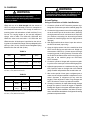
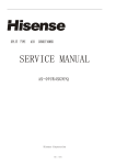
The HS29 units are designed for light commercial applica
tions, with a remotely located blower−coil unit or a furnace
with an add−on evaporator coil. Capacities for the series
are 6, 7−1/2, 10, 15 and 20 tons (21, 26, 35, 53, and 70
kW). All HS29 units use single speed scroll compressors.
The 15 (53kW) and 20 ton (70kW) units each have two
single−speed scroll compressors. The HS29 units match
with the CB17 blower−coil units. All HS29 units are three−
phase.
This manual covers HS29−072, HS29−090, HS29−120,
HS29−180 and HS29−240 units. It is divided into sections
which discuss the major components, refrigerant system,
charging procedure, maintenance and operation se
quence.
Information in this manual is intended for qualified service
technicians only. All specifications are subject to change.
Procedures in this manual are presented as a recommen
dation only and do not supersede or replace local or state
codes.
HS29−120 SHOWN
WARNING
IMPORTANT
Electric shock hazard. Can cause injury
or death. Before attempting to perform
any service or maintenance, turn the
electrical power to unit OFF at discon
nect switch(es). Unit may have multiple
power supplies.
ALL major components (indoor blower/coil) must
be matched to Lennox recommendations for
compressor to be covered under warranty. Refer to
Engineering Handbook for approved system
matchups.
WARNING
WARNING
Refrigerant can be harmful if it is inhaled. Refrigerant
must be used and recovered responsibly.
Failure to follow this warning may result in person
al injury or death.
Improper installation, adjustment, alteration,
service or maintenance can cause property
damage, personal injury or loss of life. Installation
and service must be performed by a qualified
installer or service agency.
TABLE of CONTENTS
Introduction . . . . . . . . . . . . . . . . . . . . Page 1
III START UP . . . . . . .
Specifications / Electrical . . . . . . . . . Page 2
IV CHARGING . . . . . . . . . . . . . . . . . Page 18
Parts Arrangement . . . . . . . . . . . . . . Page 4
V MAINTENANCE . . . . . . . . . . . . . . Page 22
I UNIT COMPONENTS . . . . . . . . . . Page 7
VI WIRING & OPERATION SEQUENCE
. . . . . . . . . . . . . . . . . . . . . . . . . . . . . . . Page 23
II REFRIGERANT SYSYTEM . . . . . Page 15
Page 1
. . . . . . . . . Page 17
2001 Lennox Industries Inc.
Litho U.S.A.
SPECIFICATIONS
Model No.
HS29−072−1/−2
HS29−090−2
HS29−120−2
HS29−180−2
HS29−240−2
6 (21.1)
7.5 (26.4)
10 (35.2)
15 (52.8)
20 (70.3)
Nominal Size − Tons (kW)
Liquid line (o.d.) in. (mm) connection (sweat)
5/8 (15.9)
Suction line (o.d.) in. (mm) connection (sweat)
Condenser
Coil
Net face area sq ft.
sq.
ft (m2)
1−1/8 (28.6)
1−3/8 (34.9)
(2) 1−3/8 (34.9)
29.36 (2.73) to
tal
Outer coil
12.92 (1.20)
16.35 (1.52)
Inner coil
12.59 (1.17)
15.70 (1.46)
−−−−
3/8 (9.5) − 2
3/8 (9.5) − 1
3/8 (9.5) − 2
20 (787)
15 (630)
Tube diameter in. (mm) & no. of rows
Fins per inch (m)
Diameter in. (mm) & no. of blades
Cfm (L/s) total air volume
20 (787)
15 (630)
(2) 24 (610) − 3
(4) 24 (610) − 3
(1) 1/2 (373)
(2) 1/3 (249)
(4) 1/3 (249)
8200 (3870)
16,000 (7550)
4500 (2125)
Rpm
4800 (2265)
1060
Watts
58.68 (5.45) total
(1) 24 (610) − 4
Motor hp (W)
Condenser
C
d
Fan(s)
(2) 5/8 (15.9)
1100
1075
700 total
1500 total
600
450
354 (161)
427 (193)
Hail Guards
86K90
83K36
Hot Gas Bypass Kit (hot gas bypass/superheat valve)
89K83
79K90
89K84
Hot Gas Bypass Kit (hot gas bypass valve only)
93K76
93K77
93K78
Refrigerant charge
dry air holding charge
Shipping weight lbs. (kg) 1 package
567 (257)
998 (453)
1189 (539)
Optional Accessories – Must Be Ordered Extra
79K91
not available
ELECTRICAL DATA
Model No.
HS29−072−1/−2
HS29−090−2
HS29−120−2
HS29−180−2
HS29−240−2
Line voltage data − 60 hz − 3 phase 208/230v 460v 575v 208/230v 460v 575v 208/230v 460v 575v 208/230v 460v 575v 208/230v 460v 575v
Recommended maximum fuse or
circuit breaker size (amps)
40
20
15
60
30
25
80
40
25
100
50
35
130
60
40
{Minimum circuit ampacity
27
13
11
39
20
15
53
25
18
75
39
29
95
44
32
No. of Compres
sors
Compressor
1
1
2
2
Rated load amps
(total)
18.6
9
7.4
28.8
14.7
10.8
37.8
17.2
12.4
28.8
(57.6)
14.7 10.8
(29.4) (21.6)
37.8
(75.6)
17.2 12.4
(34.4) (24.8)
Locked rotor amps
(total)
156
75
54
195
95
80
239
125
80
195
(390)
95
80
(190) (160)
239
(478)
125
80
(250) (160)
1.3
(2.6)
1
(2)
2.4
(9.6)
1.3
1 (4)
(5.2)
2.4
(9.6)
1.3
1 (4)
(5.2)
2.4
1.9
(4.8) (3.8)
4.7
(18.8)
2.4
1.9
(9.6) (7.6)
4.7
(18.8)
2.4
1.9
(9.6) (7.6)
No. of motors
Condenser
Coil
Fan Motor
FanMotor
(1 phase)
1
1
1
2
Full load amps
(total)
3
1.5
1.2
3
1.5
1.2
2.4
(4.8)
Locked rotor amps
(total)
6
3
2.9
6
3
2.9
4.7
(9.4)
{Refer to National or Canadian Electrical Code manual to determine wire, fuse and disconnect size requirements.
NOTE Extremes of operating range are plus and minus 10% of line voltage.
HACR type (under 100 amps). U.S. only.
Page 2
4
4
SPECIFICATIONS
Model No.
G
General
D
Data
HS29−072−3
HS29−090−3
HS29−120−3
6 (21.1)
7.5 (26.4)
10 (35.2)
Nominal Size − Tons (kW)
Connections
(
(sweat)
t)
5/8 (15.9)
5/8 (15.9)
5/8 (15.9)
Suction line (o.d.) − in. (mm)
Liquid line (o.d.) − in. (mm)
1−1/8 (28.6)
1−3/8 (34.9)
1−3/8 (34.9)
Net face area − sq. ft. (m2) Outer coil
12.92 (1.20)
22.50 (2.09)
29.36 (2.73) total
Inner coil
12.59 (1.17)
21.70 (2.02)
−−−
3/8 (9.5) − 2
3/8 (9.5) − 2
3/8 (9.5) − 2
20 (787)
20 (787)
15 (630)
(1) 24 (610) − 4
(1) 24 (610) − 4
(2) 20 (610) − 3
Motor hp (W)
(1) 1/2 (373)
(1) 3/4 (560)
(2) 1/3 (249)
cfm (L/s) total air volume
4500 (2125)
5150 (2430)
8200 (3870)
1075
1060
1100
Refrigerant
Condenser
C il
Coil
dry air holding charge
Tube diameter − in. (mm) & no. of rows
Fins per inch (m)
Condenser
F ( )
Fan(s)
Diameter − in. (mm) & no. of blades
Rpm
Watts
600
570
700 total
319 (145)
405 (184)
567 (257)
Hail Guards
29M43
29M44
79K91
Hot Gas Bypass Kit (bypass to suction)
28M73
79K90
89K84
Hot Gas Bypass Kit (bypass to evaporator)
28M72
93K77
93K78
Shipping
lbs. (kg) 1 package
Optional Accessories – Must Be Ordered Extra
ELECTRICAL DATA
General
Data
Model No.
HS29−072−3
HS29−090−3
HS29−120−3
Line voltage data − 60 hz − 3 phase 208/230v 460v 575v 208/230v 460v 575v 208/230v 460v 575v
Compressor
Condenser
F M t
FanMotor
(1 phase)
Recommended maximum fuse or
circuit breaker size (amps)
40
20
15
60
35
25
80
40
25
{Minimum circuit ampacity
27
13
11
40
21
16
54
25
18
No. of Compressors
1
1
1
1
1
1
1
1
1
Rated load amps (total)
18.6
9
7.4
28.8
14.7
10.8
37.8
17.2
12.4
Locked rotor amps (total)
156
75
54
195
95
80
239
125
80
No. of motors
1
1
1
1
1
1
2
2
2
Full load amps (total)
3
1.5
1.2
3.7
1.9
1.6
2.4
(4.8)
1.3
(2.6)
1
(2)
Locked rotor amps (total)
6
3
2.9
7.3
3.7
3.4
4.7
(9.4)
2.4
1.9
(4.8) (3.8)
{Refer to National or Canadian Electrical Code manual to determine wire, fuse and disconnect size requirements.
NOTE Extremes of operating range are plus and minus 10% of line voltage.
HACR type (under 100 amps). U.S. only.
Page 3
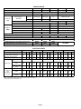
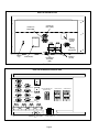
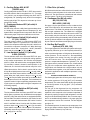
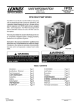
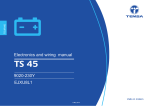
HS29−072−3 & HS29−090−3 PARTS ARRANGEMENT
(HS29−072−3 shown)
CONDENSER FAN
(B4)
CONTROL BOX
HIGH PRESSURE SWITCH (S4)
LOW PRESSURE SWITCH
(S87)
LOW AMBIENT SWITCH (S11)
COMPRESSOR
(B1)
LIQUID LINE
SERVICE VALVE
FIGURE 1
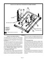
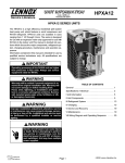
HS29−120−3 PARTS ARRANGEMENT
CONDENSER FANS
(B4, B5)
CONTROL BOX
COMPRESSOR
(B1)
HIGH PRESSURE SWITCH
(S4)
SUCTION LINE
SERVICE VALVE
LOW AMBIENT SWITCH (S11)
(on liquid line not shown)
LOW PRESSURE SWITCH (S87)
(on suction line not shown)
LIQUID LINE
SERVICE VALVE
FIGURE 2
Page 4
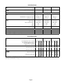
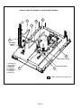
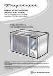
HS29−180 & HS29−240 PARTS ARRANGEMENT
(B21)
(B4)
(B22)
SLIDE−OUT
CONTROL BOX
CONDENSER FANS
(B4, B5, B21, B22)
(B5)
LOW PRESSURE
SWITCH (S87)
ACCESS PANEL
LOW PRESSURE
SWITCH (S88)
SUCTION LINE
SERVICE VALVE
(TYP.)
HIGH PRESSURE
SWITCH (S7)
LOW AMBIENT
SWITCH (S84)
LIQUID LINE
SERVICE VALVE (TYP.)
HIGH PRESSURE
SWITCH (S4)
LOW AMBIENT SWITCH
(S11) ON LIQUID LINE NOT SHOWN
COMPRESSOR (B1)
1st, STAGE COOL
COMPRESSOR (B2)
2nd. STAGE COOL
FIGURE 3
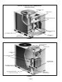
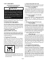
HS29−072 & HS29−090 CONTROL BOX
outdoor fan relay latching relay
(K10)
(K167)
ground lug
capacitor
(C1)
contactor
(K1)
FIGURE 4
Page 5
minimum
run timer
(DL33)
HS29−120 CONTROL BOX
outdoor fan
relay 1 (K10)
outdoor fan
relay 2 (K68)
minimum
run timer
(DL33)
latching
relay (K167)
ground
lug
contactor (K1)
capacitor
(C1,C2)
low ambient
thermostat
(S41)
FIGURE 5
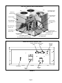
HS29−180 & HS29−240 CONTROL BOX
K58 LOW AMB. KIT
TIMER DL33
K167 LATCHING 1 K10 OUTDOOR FAN 1
CIRCUIT BREAKER CB7
(208/230V ONLY)
CONTACTOR K1
K168 LATCHING 2 K68 OUTDOOR FAN 2
TIMER DL34
K66 STAGE 1 COOL K149 OUTDOOR FAN 3
TERMINAL
STRIP
K67 STAGE 2 COOL K150 OUTDOOR FAN 4
TB35
C1
C2
C18
C19
LOW AMBIENT THERMOSTAT
(S41)
TRANSFORMER T18
FIGURE 6
Page 6
CONTACTOR K2
I−UNIT COMPONENTS
3 − Terminal Strip TB35 (180, 240)
TB35 terminal strip distributes 24V power and common
from the transformer T18 to the control box components.
ELECTROSTATIC DISCHARGE (ESD)
Precautions and Procedures
4 − Condenser Fan Capacitors
C1, C2, C18, C19
CAUTION
Electrostatic discharge can affect electronic
components. Take precautions during unit instal
lation and service to protect the unit’s electronic
controls. Precautions will help to avoid control
exposure to electrostatic discharge by putting
the unit, the control and the technician at the
same electrostatic potential. Neutralize electro
static charge by touching hand and all tools on an
unpainted unit surface before performing any
service procedure.
The HS29−072/090 components are shown in figure 1. The
HS29−120 components are shown in figure 2 and the
HS29−180/240 components are in figure 3.
A−CONTROL BOX COMPONENTS
The HS29−072/090 control box components are shown in
figure 4. The HS29−120 control box components are shown
in figure 5 and the HS29−180/240 control box components
are in figure 6. The control box for the HS29−072/090 and
120 units is located in a separate compartment. The
HS29−180/240 has a slide−out control box.
1 − Disconnect Switch S48
(Option on HS29−1 and −2 units)
Some HS29 units may be equipped with an optional dis
connect switch S48. S48 is a factory−installed toggle switch
which can be used to disconnect power to the unit. S48 is
located on the opposite side of the unit from the control box
on HS29−180/240 units.
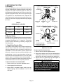
2 − Transformer T18 (180, 240)
The HS29 15 and 20 ton units use a line voltage to
24VAC transformer mounted in the control box. Trans
former T18 supplies power to control circuits in the
HS29 unit.The transformer is rated at 70VA and is pro
tected by a 3.5 amp circuit breaker (CB18). CB18 is in
ternal to the transformer. The 208/230 (Y) voltage trans
formers use two primary voltage taps as shown in figure
208/230V TRANSFORMER 7, while 460 (G) and 575
BLUE
YELLOW
(J) voltage transformers
SECONDARY
use a single primary
voltage tap.
208 VOLTS
RED
230 VOLTS
ORANGE PRIMARY
BLACK
FIGURE 7
NOTE−208 volt units are field wired with the red wire
connected to control transformer. 230 volt units are
factory wired with the orange wire connected to control
transfomer primary.
Page 7
All HS29 units use single−phase condenser fan motors. Motors
are equipped with a fan run capacitor to maximize motor effi
ciency. Condenser fan capacitors C1, C2, C18 and C19 assist
in the start up of condenser fan motors B4, B5, B21 and B22.
Capacitor ratings will be on condenser fan motor nameplate.
5 − Compressor Contactor K1 (all units)
K2 (180/240)
All compressor contactors are three−pole double− break
contactors with a 24V coil. In HS29−072/090 and the
HS29−120 units, K1 energizes compressor B1. In
HS29−180/240 units, K1 and K2 energize compressors B1
and B2.
6 − Minimum Run Timer DL33 (all units)
DL34 (180/240)
All HS29 units have a minimum run time control which pre
vents the compressor from short cycling. The timer allows
the compressor to run approximately 5 minutes before
shut−down, to prevent short cycling due to irregular or rapid
on−off selection at the indoor thermostat mode. This 5 min
ute run time also allows oil circulation back to the compres
sor. DL33 and DL34 are one component of an integral two
component run time circuit. The timer is activated by an in
put from the latching relay. Do not bypass the control.
7 − Latching Relay K167 (all units) &
K168 (180, 240)
Latching relays K167(1st stage) and K168 (2nd stage) are
N.O. 3PDT relays used in all units. Units with a single com
pressor will use DPDT relays. When there is demand from
the indoor thermostat, K167 closes energizing timer DL33
which begins a 5 minute minimum run time. If thermostat
demand is satisfied or low pressure switch S87 opens with
in the 5 minute run time, DL33 will maintain input to the
latch relay to keep the system operating. In the
HS29−180/240 units, K167 and K168 close energizing tim
ers DL33 and DL34.
8 − Low Ambient Thermostat S41
(120, 180/240) & Relay K58 (180/240)
HS29−120 and HS29−180/240 units have a low ambient
thermostat. S41 is a N.C. switch which opens on tempera
ture fall at 55+ 5_F. The switch resets when temperature
rises to 65+ 6_F. On the HS29−120, S41 opens and de−en
ergizes K68 which de−energizes outdoor fan B5. On the
HS29−180/240 S41 opens and de−energizes low ambient
DPDT relay K58. This, in turn, de−energizes fan relays K68
and K150 which de−energize outdoor fans B5 and B22.
When S41 closes, fans are re−energized on all units.This
intermittent fan operation increases indoor evaporator coil
temperature to prevent icing.
9 − Condenser Fan Relay K10 (all units)
K68 (120,180,240)
K149, K150 (180, 240)
Condenser fan relays K10 and K149 are DPDT and relays
K68 and K150 are SPDT with a 24V coil. In all units K10 en
ergizes condenser fan B4 (fan 1) in response to thermostat
demand. In the HS29−120,180 and 240, K68 energizes
condenser fan B5 (fan 2) in response to thermostat de
mand. In the HS29−180/240, K149 and K150 energize
condenser fans B21 (fan 3) and B22 (fan 4), in response to
thermostat demand.
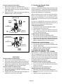
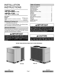
SCROLL COMPRESSOR
DISCHARGE
SUCTION
GFI− J11
(Option on HS29−1 and −2 units)
Some HS29 units may be equipped with a 110v ground
fault interrupter (GFI) receptacle. The GFI is located on the
control box panel on the HS29−072/090 and 120. The GFI
is located in a separate box on the opposite side of unit form
the control box on the HS29−180/240. Separate wiring
must be run for the 110v receptacle.
10 − Circuit Breaker CB7 (180/240 Y only)
Circuit breaker CB7 is a manual reset switch that provides
overcurrent protection to condenser fans B4, B5, B21 and
B22. The breaker is rated at 15 amps.
B−COOLING COMPONENTS
WARNING
Refrigerant can be harmful if it is inhaled. Refrigerant
must be used and recovered responsibly.
Failure to follow this warning may result in person
al injury or death.
FIGURE 8
The scroll compressor design is simple, efficient and requires
few moving parts. A cutaway diagram of the scroll compressor
is shown in figure 8. The scrolls are located in the top of the
compressor can and the motor is located just below. The oil
level is immediately below the motor.
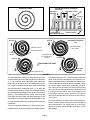
The scroll is a simple compression concept centered around
the unique spiral shape of the scroll and its inherent properties.
Figure 9 shows the basic scroll form. Two identical scrolls are
mated together forming concentric spiral shapes (figure 10).
One scroll remains stationary, while the other is allowed to "or
bit" (figure 11). Note that the orbiting scroll does not rotate or
turn but merely orbits the stationary scroll.
NOTE − During operation, the head of a scroll compressor may
be hot since it is in constant contact with discharge gas.
1 − Compressor B1 (all units) B2 (180/240)
ALL HS29 −072/090, 120 and 180/240 model units use
scroll compressors. Compressor B1 operates during all
cooling demand and is energized by contactor K1 upon re
ceiving first stage demand. Compressor B2 operates only
during second stage cooling demand, and is energized by
contactor K2. See ELECTRICAL section or compressor
nameplate for compressor specifications.
IMPORTANT
Three−phase scroll compressor noise will be sig
nificantly higher if phasing is incorrect. Compres
sor will operate backwards so unit will not provide
cooling. If phasing is incorrect, disconnect power
to unit and reverse any two power leads (L1 and
L3) prefered) to unit.
Page 8
CROSS−SECTION OF SCROLLS
SCROLL FORM
DISCHARGE
STATIONARY SCROLL
DISCHARGE
PRESSURE
SUCTION
FIGURE 9
TIPS SEALED BY
DISCHARGE PRESSURE
ORBITING SCROLL
FIGURE 10
SUCTION
SUCTION
INTERMEDIATE PRESSURE
GAS
2
1
CRECENT SHAPED
ORBITING SCROLL
GAS POCKET
STATIONARY SCROLL
SUCTION
FLANKS SEALED
POCKET
SUCTION
BY CENTRIFIGUAL
FORCE
SUCTION
MOVEMENT OF ORBIT
3
4
DISCHARGE
POCKET
HIGH PRESURE GAS
FIGURE 11
The counterclockwise orbiting scroll draws gas into the outer
crescent shaped gas pocket created by the two scrolls (figure
11− 1). The centrifugal action of the orbiting scroll seals off the
flanks of the scrolls (figure11−2). As the orbiting motion contin
ues, the gas is forced toward the center of the scroll and the
gas pocket becomes compressed (figure 11− 3). When the
compressed gas reaches the center, it is discharged vertically
into a chamber and discharge port in the top of the compressor
(figure 10). The discharge pressure forcing down on the top
scroll helps seal off the upper and lower edges (tips) of the
scrolls (figure 10). During a single orbit, several pockets of gas
are compressed simultaneously providing smooth continuous
compression.
The scroll compressor is tolerant to the effects of liquid return.
If liquid enters the scrolls, the orbiting scroll is allowed to sepa
Page 9
rate from the stationary scroll. The liquid is worked toward the
center of the scroll and is discharged. If the compressor is re
placed, conventional Lennox cleanup practices must be used.
Due to its efficiency, the scroll compressor is capable of draw
ing a much deeper vacuum than reciprocating compres
sors. Deep vacuum operation can cause internal fusite
arcing resulting in damaged internal parts and will result
in compressor failure. Never use a scroll compressor for
evacuating or pumping−down" the system. This type of
damage can be detected and will result in denial of war
ranty claims.
The scroll compressor is quieter than a reciprocating com
pressor, however, the two compressors have much different
sound characteristics. The sounds made by a scroll com
pressor do not affect system reliability, performance, or indi
cate damage.
2 − Cooling Relays K66 & K67
(180/240 only)
Cooling relays K66 and K67 are N.O. 3PDT relays used in
the HS29−180/240. K66 is energized from "Y1" (1st stage
cool), which in turn energizes latching relay K167. K67 is
energized by "Y2" (2nd stage cool), which in turn energizes
latching relay K168. This sequence is the start up of com
pressors B1 and B2.
3 − Crankcase Heaters HR1 (all units) &
HR2 (180/240)
All LSA series units use a belly−band type crankcase heat
er. Heater HR1 is wrapped around compressor B1 and
heater HR2 is wrapped around compressor B2. HR1 and
HR2 assure proper compressor lubrication at all times.
4 − High Pressure Switch S4 (all units) &
S7 (120, 180/240)
The high pressure switch is a manual−reset SPST N.C.
switch which opens on a pressure rise. The switch is lo
cated in the compressor discharge line and is wired in se
ries with the compressor contactor coil. When discharge
pressure rises to 450 + 10 psig (3101 + 69 kP ) the switch
opens and the compressor is de−energized.
5 − Low Ambient Switch S11 (all units)
& S84 (180/240)
The low ambient switch is an auto−reset SPST N.O. pres
sure switch, which allows for mechanical cooling operation
at low outdoor temperatures. All LSA units are equipped
with S11. HS29−180 and 240 units are equipped with both
S11 and S84. A switch is located in each liquid line. In all
HS29 units, S11 is wired in series with fan relay K10. In the
HS29−180 and 240, S84 is wired in series with fan relay
K149. When liquid pressure rises to 275 + 10 psig (1896 +
69 kPa), the switch closes and the condenser fan is ener
gized. When the liquid pressure drops to 150 + 10 psig
(1034 + 69 kPa) the switch opens and the condenser fan in
that refrigerant circuit is de−energized. This intermittent fan
operation results in higher evaporating temperature, allow
ing the system to operate without icing the evaporator coil
and losing capacity.
6 − Low Pressure Switches S87(all units)
S88 (180/240)
The low pressure switch is an auto−reset SPST N.O. switch
which opens on pressure drop. All HS29 units are equipped
with S87. HS29−180 and 240 units are equipped with both,
S87 and S88. The switch is located on the suction line and
is wired in series with the thermostat. S87 is wired in series
with Y1 and S88 is wired in series with Y2. When suction
pressure drops to 25 + 5 psig (172 + 34 k Pa), the switch
opens and the compressor is de−energized. The switch au
tomatically resets when pressure in the suction line rises to
55 + 5 psig (379 + 34 kPa).
7 − Filter Drier (all units)
All HS29 model units have a filter drier that is located in the
liquid line of each refrigerant circuit at the exit of each con
denser coil. The drier removes contaminants and moisture
from the system. The drier is field installed.
8 − Condenser Fan B4 (all units)
B5 (120,180/ 240)
B21 & B22 (180/ 240)
See page 2 for the specifications on the condenser fans
used in the HS29 units. All condenser fans have single−
phase motors. The HS29−072 and 090 units are equipped
with a single condenser fan. The HS29−120 is equipped
with two fans. HS29−180 and 240 units have four fans. The
fan assembly may be removed for servicing by removing
the fan grill and turning the assembly until the motor brack
ets line up with the notches in the top panel. Lift the assem
bly out of the unit and disconnect the jack plug on the motor.
9 − Hot Gas By−Pass Kit
Optional (072, 090, 120)
The hot gas bypass kit is used with split system units requir
ing capacity reduction (up to 6 tons capacity reduction) in
order to prevent evaparator coil icing due to abnormally low
suction pressure. The kit consists of : De−superheating
valve (bypass to the suction line only), hot gas by−pass
valve and service valve. The de−superheating valve is
pressure compensated/temperature activated. The hot
gas bypass valve is pressure activated. The kit will redirect
hot gas to the evaporator where applications call for a
single indoor unit matched with a single outdoor unit and
are installed close together, or into the suction line which is
preferred in applications with multiple evaporators or long
refrigerant lines.
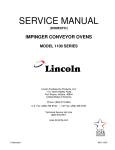
BYPASS TO EVAPORATOR FIGURE 12
The discharge bypass valve is factoryset to begin opening
at a suction pressure of 57.5 psig [32°F (0°C) saturation
temperature]. The valve should reach its fully open position
at a suction pressure of 50 psig [26°F (−3°C) saturation
temperature].
The hot gas is then bypassed into the evaporator coil
through the sideconnection distributor. The coil’s thermal
expansion valve responds to the increased superheat of
the vapor by opening to supply liquid refrigerant to cool the
hot gas to the desired temperature. Also, since the evapo
rator is an excellent mixing chamber, a dry vapor going into
the compressor suction line is ensured. For flow diagram
see figure 15.
This method improves oil return from the evaporator, since
the hot gas keeps velocities higher. Refer to Refrigerant
Piping Guideline manual (Corp. 9351−L9).
Page 10
HS29−072−3 HOT GAS BYPASS TO EVAPORATOR PLUMBING ASSEMBLY
H
G
E
liquid line
low ambient pressure switch
J
E − Discharge line
F − Mixing line
G − Discharge line
H − Discharge line
I − Suction line
J − Mixing line
Shaded Components Provided In Kit
high pressure switch
I
low pressure switch
F
FIGURE 12
BYPASS TO SUCTION LINE FIGURE 13
The discharge bypass valve is factory−set to begin opening
at a suction pressure of 57.5 psig (32_F (0_C) saturation
temperature). The valve should reach its fully open position
at a suction pressure of 50 psig (26_F (−3_C) saturation
temperature).
The hot gas is then bypassed into the suction line upstream
of the thermal sensing bulb. The de−superheating thermal
expansion valve then opens to supply liquid refrigerant to
cool the hot gas to the desired suction temperature.
This method reduces flow through the evaporator and suc
tion lines. Special handling of suction risers is required. Re
fer to Refrigerant Piping Guideline manual (Corp.
9351−L9). For flow diagram see figure14.
a − De−Superheat Valve (TXV)
The de−superheat valve, together with the hot gas bypass
valve, de−super heats the vapor going back to the com
pressor. In order to maintain proper compressor operating
temperatures, the de−superheat valve will add liquid refrig
Page 11
erant to cool the vapor to acceptable temperatures for the
compressor. Superheat is the difference between the tem
perature of the refrigerant vapor and its saturation temper
ature.
b − Hot Gas Bypass Valve
The hot gas bypass valve responds to changes down
stream of the hot gas injection into the suction line, or suc
tion pressure. When the evaporating pressure is above the
valve setting, the valve remains closed. As the suction
pressure drops below the valve setting the valve responds
and begins to open. As the suction pressure continues to
drop, the valve continues to open farther until limit of valve
stroke is reached.
c − Service Valve
All hot gas by−pass kits are equipped with a service valve
located in the mixing line. The service valve is manually op
erated valve. The service port is used for leak testing and
evacuating.
HS29−072−3 HOT GAS BYPASS TO SUCTION LINE ASSEMBLY
O
M
N
I
C
low ambient
pressure
switch
14K3801
R
high pressure switch
C − Discharge line
I − Discharge line
K − Mixing line
L − Suction line
M − Liquid line
N − Discharge line
O − Liquid line
R − Mixing line
low pressure switch
K
L
Shaded components are provided in kit.
FIGURE 13
Page 12
HOT GAS BYPASS TO SUCTION SCHEMATIC FLOW DIAGRAM
DESUPERHEATING
VALVE
EVAPORATOR
UNIT #2
EVAPORATOR COIL
CONDENSER COIL
DISCHARGE
BYPASS
VALVE
EVAPORATOR
UNIT #1
MANUAL
SHUT OFF
VALVE
SUCTION LINE
SERVICE VALVE
EXPANSION
VALVE
EVAPORATOR COIL
CONDENSING
UNIT
EXPANSION
VALVE
COMPRESSOR
SOLENOID
VALVE
LIQUID LINE
SERVICE VALVE
SOLENOID
VALVE
FIGURE 14
Hot Gas Bypass Performance Check
1. Start unit. After unit operating conditions have sta
bilized, check unit volts and amps. These must be
within range shown on unit nameplate.
2. Remove unit access panel. Determine whether or
not unit is operating normally in hot gas bypass
mode. The unit is operating normally in hot gas by
pass mode to the suction line if suction line super
heat temperatures range from 35°F (19.5°C) to
45°F (25°C) with suction line pressures less than
57.5 psig (32°F (0°C) saturated temperature). The
unit is operating normally without hot gas bypass if
suction line superheat temperatures range from 10°F
(5.5°C) to 20°F (11°C) with suction line pressures
greater than 57.5psig (32°F (0°C) saturated temper
ature). The unit is operating normally in hot gas by
pass mode to the evaporator if suction line super
heat temperatures are greater than 20_F (11_C) with
suction line pressures greater than or equal to 57.5
psig (32°F (0°C) saturated temperature). The unit is
Page 13
operating normally without hot gas bypass if suction
line superheat temperatures range from 10°F (5.5°C)
to 20°F (11°C) with suction line and discharge pres
sures occurring within the range listed in table 4 on
page18 .
Note − See figure 13 for location of pressure/tempera
ture measurement for by pass to the suction line. (Re
move low pressure switch during pressure measure
ment, then reinstall upon completion.) For by pass to
the evaporator take pressure/temperature measure
ment close to compressor.
Note − Superheat values are calculated as follows:
a − measure suction line pressure − for example 57.5
psig
b − convert 57.5 psig via pressure/temperature chart
for HCFC22 to 32°F (0°C) saturation temperature.
c − measure suction line temperature − for example
77°F (25°C).
d − then superheat = 77°F(25°C) − 32°F(0°C) =
45°F(25°C).
CONDENSING
UNIT
CB17/CBH17−95
BLOWER COIL UNIT
DISCHARGE
BYPASS
VALVE
SIDECONNECTION
DISTRIBUTOR
MANUAL
SHUT OFF
VALVE
CHECK VALVE
SUCTION LINE
SERVICE VALVE
COMPRESSOR
EVAPORATOR COIL #1
CONDENSER COIL
EXPANSION
VALVE
EVAPORATOR COIL #2
BYPASS TO EVAPORATOR SCHEMATIC FLOW DIAGRAM
LIQUID LINE
SERVICE
VALVE
CHECK VALVE
SOLENOID VALVE
SIDECONNECTION
DISTRIBUTOR
EXPANSION
VALVE
FIGURE 15
3. If unit is operating normally without hot gas bypass,
the correct amount. Check to make sure that the
initiate hot gas bypass by either gradually closing
valve core has been removed from the suction
liquid line service valve, reducing air flow to evapo
line pressure tap fitting.
rator(s), or, in multi−evaporator units, shutting off an
The hot gas bypass circuit may be operating with
evaporator(s).
an evaporator load of less than the 2 ton mini
4. If normal hot gas bypass suction line superheat and
mum.
pressures are not obtained check the following:
b − If bypass to the suction line superheat values are
a − Pressures are less than 57.5 psig for both by
greater than 45°F (25°C) −
pass to the suction line or evaporator. If bypass
The desuperheating valve may not be opening
to the evaporator superheat values are less than
the correct amount. Check to make sure the
20_F (11_C)−
sensing bulb has adequate thermal contact with
The manual shut−off valve may be closed. Open
the suction line.
it.
The discharge bypass valve may not be opening
5. Re−install unit access panel.
Page 14
II− REFRIGERANT SYSTEM
A−Plumbing
Liquid And Suction Line Service Valve
(Valve Open)
Field refrigerant piping consists of liquid and suction lines
from the condensing unit (sweat connections) to the indoor
evaporator coil (sweat connections). Refer to table 1 for
field−fabricated refrigerant line sizes. Refer to Lennox Re
frigerant Piping manual Corp. 9351−L9 for proper size, type
and application of field−fabricated lines. Separate dis
charge and suction service ports are provided at the com
pressor for connection of gauge manifold during charging
procedure.
service
port
to outdoor coil
HS29
UNIT
LIQUID
LINE
SUCTION
LINE
−072
5/8 in
(16 mm)
1−1/8 in
(29 mm)
−090, −120,
−180, −240
5/8 in
(16 mm)
1−3/8 in
(35 mm)
to indoor coil
Schrader
valve
service port
cap
TABLE 1
REFRIGERANT LINE SIZES
stem cap
insert hex
wrench here
Liquid And Suction Line Service Valve
(Valve Closed)
stem cap
service
port
to outdoor coil
insert hex
wrench here
B−Service Valves
All HS29 units are equipped with service valves located in
the suction and liquid lines. The service valves are manual
ly operated. See figures 16, 17, 18 and 19 . The service
ports are used for leak testing, evacuating, charging and
checking charge.
1 − Liquid Line Service Valve
The liquid line valve made by one of several manufacturers
may be used. All liquid line service valves function the
same way, differences are in construction. Valves are not
rebuildable. If a valve has failed it must be replaced. All
HS29−072, −090 and −120 units and HS29−180/240−2 units
produced after 10−01−01, use valves shown in figure 16.
HS29−180/240 units produced before 10−01−01 use valves
shown in figure 17. A schrader valve is factory installed. A
service port is supplied to protect the schrader valve from
contamination and to serve as the primary leak seal.
service
port cap
to indoor coil
Schrader valve open
to line set when valve is
closed (front seated)
(valve front seated)
FIGURE 16
HS29−072, −090, −120
To Open Liquid Line Service Valve:
1 − Remove stem cap with an adjustable wrench.
2 − Using service wrench and 5/16" hex head extension if
needed (part #49A71) back the stem out counterclock
wise until the valve stem just touches the retaining ring.
3 − Replace stem cap. Tighten finger tight, then tighten an
additional 1/6 turn. Do not over torque.
DANGER
To Access Schrader Port: All HS29 UNITS
1 − Remove service port cap with an adjustable wrench.
2 − Connect gauge to the service port.
3 − When testing is completed, replace service port cap.
Tighten finger tight, then an additional 1/6 turn. Do not
over torque.
Page 15
HS29−1 and −2 units are equipped with service
valves with a retaining ring. Do not attempt to
backseat these valves past the retaining ring.
Attempts to backseat these valves past the
retaining ring will cause snap ring to explode from
valve body under pressure of refrigerant. Personal
injury and unit damage will result.
To Close Liquid Line Service Valve:
1 − Remove stem cap with an adjustable wrench.
2 − Using service wrench and 5/16" hex head extension if
needed (part #49A71), turn stem clockwise to seat the
valve. Tighten firmly.
3 − Replace stem cap. Tighten finger tight, then tighten an
additional 1/6 turn. Do not over torque.
LIQUID LINE SERVICE VALVE (VALVE OPEN)
HS29−180, 240
INSERT
WRENCH
HERE
STEM
CAP
TO
CONDENSER COIL
PORT
CAP
OUTLET (TO
INDOOR COIL)
VALVE CORE
LIQUID LINE SERVICE VALVE (VALVE CLOSED)
RETAINING RING
(early HS29 models only)
STEM
CAP
TO
CONDENSER COIL
OUTLET (TO
INDOOR COIL)
PORT CAP
(VALVE
FRONT
SEATED)
FIGURE 17
HS29−180/240
To Open Liquid Line Service Valve:
1 − Remove stem cap with an adjustable wrench.
2 − Using service wrench back the stem out counterclock
wise until the valve stem just touches the retaining ring.
3 − Replace stem cap tighten firmly. Tighten finger tight, then
tighten an additional 1/6 turn. Do not over torque.
To Close Suction Line Service Valve:
1 − Remove stem cap with an adjustable wrench.
2 − Using service wrench and turn stem in clockwise to seat
the valve. Tighten firmly.
3 − Replace stem cap. Tighten finger tight, then tighten an
additional 1/6 turn. Do not over torque.
2 − Suction Line Service Valve
HS29−072−1
A full service front and back seating suction line service valve
is used on HS29−072−1 series units. Different manufacturers
of valves may be used. All suction line service valves function
the same way, differences are in construction.
Valves manufactured by Parker are forged assemblies.
Primore and Aeroquip valves are brazed together.
Valves are not rebuildable. If a valve has failed, it must
be replaced. The suction line service valve is illustrated
in figure 18.
The valve is equipped with a service port. There is no
schrader valve installed in the suction line service port. A
service port cap is supplied to seal off the port.
To Access Schrader Port:
1 − Remove service port cap with an adjustable wrench.
2 − Connect gauge to the service port.
3 − When testing is completed, replace service port
cap. Tighten finger tight, then tighten an additional
1/6 turn. Do not over torque.
To Open Suction Line Service Valve:
1 − Remove stem cap with an adjustable wrench.
2 − Using service wrench back the stem out counterclock
wise until the valve stem just touches the retaining ring.
3 − Replace stem cap tighten firmly. Tighten finger tight, then
tighten an additional 1/6 turn. Do not over torque.
To Close Suction Line Service Valve:
1 − Remove stem cap with an adjustable wrench.
2 − Using service wrench and turn stem in clockwise to seat
the valve. Tighten firmly.
3 − Replace stem cap. Tighten finger tight, then tighten an
additional 1/6 turn. Do not over torque.
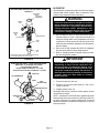
3 − Suction Line Service Valve
HS29−072−2/−3, HS29−090, −120, −180/240
The HS29072−2, −3 and all HS29−090 through −240 model
units are equipped with a full service ball valve, as shown
in figure 19. One service port that contains a valve core is
present in this valve. A cap is also provided to seal off the
service port. The valve is not rebuildable so it must always
be replaced if failure has occurred.
Opening the Suction Line Service Valve
1 − Remove the stem cap with an adjustable wrench.
2 − Using a service wrench, turn the stem counterclock
wise for 1/4 of a turn.
3 − Replace the stem cap and tighten it firmly.
Closing the Suction Line Service Valve
1 − Remove the stem cap with an adjustable wrench.
2 − Using a service wrench, turn the stem clockwise for 1/4
of a turn.
3 − Replace the stem cap and tighten firmly.
Page 16
SUCTION LINE SERVICE VALVE (VALVE OPEN)
HS29−072−1
VALVE FRONT
SEATED
OUTLET (TO
COMPRESSOR)
III−STARTUP
The following is a general procedure and does not apply to
all thermostat control systems. Refer to sequence of op
eration in this manual for more information.
WARNING
SERVICE
PORT
Crankcase heaters must be energized for 24 hours
before attempting to start compressors. Set ther
mostat so there is no compressor demand before
closing disconnect switch. Attempting to start
compressors during the 24−hour warm −up period
could result in damage or failed compressors.
SERVICE
PORT
CAP
1 − Set fan switch to AUTO or ON and move the system
selection switch to COOL. Adjust the thermostat to a
setting far enough below room temperature to bring on
compressors. Compressors will start and cycle on de
mand from the thermostat (allowing for unit and thermo
stat time delays).
2 − Each circuit is field charged with HCFC−22 refrigerant.
See unit name plate for correct charge amount.
3 − Refer to Charging section for proper method of check
ing and charging the system.
FROM INDOOR COIL
NO VALVE CORE
VALVE
STEM
STEM
CAP
NOTE−When valve is front seated, service port is
not isolated (blocked off) from system.
IMPORTANT
FIGURE 18
Threephase scroll compressors must be phased
sequentially to ensure correct compressor rota
tion and operation. At compressor startup, a rise
in discharge and drop in suction pressures indi
cate proper compressor phasing and operation. If
discharge and suctions pressures do not perform
normally, follow the steps below to correctly
phase in the unit.
SUCTION LINE (BALL TYPE) SERVICE VALVE
HS29−072−2, −3, HS29−090, 120, 180,240
USE ADJUSTABLE WRENCH
ROTATE STEM CLOCKWISE 90_ TO CLOSE
ROTATE STEM COUNTERCLOCKWISE 90_ TO OPEN
STEM CAP
TO COMPRESSOR
STEM
BALL
(SHOWN OPEN)
FROM INDOOR COIL
SERVICE PORT
CAP
SERVICE PORT
VALVE CORE
FIGURE 19
Page 17
1 − Disconnect power to the unit.
2 − Reverse any two field power leads (L1 and L3 pre
ferred) to the unit.
3 − Reapply power to the unit.
Discharge and suction pressures should operate at their
normal startup ranges.
NOTE − Compressor noise level will be significantly higher
when phasing is incorrect and the unit will not provide cool
ing when compressor is operating backwards. Continued
backward operation will cause the compressor to cycle on
internal protector.
IV− CHARGING
WARNING
WARNING
Refrigerant can be harmful if it is inhaled. Refrigerant
must be used and recovered responsibly.
Failure to follow this warning may result in person
al injury or death.
Never use oxygen to pressurize refrigeration or air
conditioning system. Oxygen will explode on con
tact with oil and could cause personal injury.
A−Leak Testing
Using an Electronic or Halide Leak Detector
HS29 units are to be field charged with the amount of
HCFC−22 refrigerant indicated on the unit nameplate or
unit Installation Instructions. This charge is based on a
matching indoor coil and outdoor coil with a 25 foot (7.6 m)
line set. For varying lengths of line set and refrigerant
charge, refer to table 2 for HS29−072, HS29−090 and
HS29−120 series units and table 3 for HS29−180 and
HS29−240 units. A blank space is provided on the unit rat
ing plate to list actual field charge. Units are designed for line
sets up to 50ft. (15.2m). Consult Lennox Refrigerant Piping
Manual for line sets over 50ft. (51.2m).
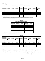
TABLE 2
UNIT
HCFC−22 FOR 25 FT. (7.6M)
LINE SET
Adjust per 1ft
(.3m) *
HS29−072
12 lbs. 8 ozs. (5.7kg)
1.8 ozs. (51g)
HS29−090−2
HS29−090−3
16 lbs. 0 ozs. (7.5kg)
17 lbs. 8 ozs. (7.94)
1.8 ozs. (51g)
HS29−120
23 lbs 8 ozs. (10.4kg)
1.8 ozs. (51g)
*If line set is greater than 25 ft. (7.6m) add this amount. If line set is less
than 25 ft. (7.6m) subtract this amount.
TABLE 3
HCFC−22 per 25 ft. (7.6m)
Adjust per 1 ft. (.3m)
UNIT
Circiut 1
Circuit 2
Each Circuit
HS29−180
14.5 lbs.
(6.6kg)
14.5 lbs.
(6.6 kg)
1.8 ozs. (51 g)
HS29−240
22 lbs.
(10kg)
22 lbs.
(10 kg)
1.8 ozs. (51 g)
**If line set is greater than 25 ft. (7.6m) add this amount. If line set is less
than 25 ft. (7.6m) subtract this amount.
1 − Connect a cylinder of HCFC−22 with a pressure regu
lating valve to the center port of the manifold gauge set.
2 − Connect the high pressure hose of the manifold gauge
set to the service port of the suction valve. (Normally,
the high pressure hose is connected to the liquid line
port; however, connecting it to the suction port better
protects the manifold gauge set from high pressure
damage.)
3 − With both manifold valves closed, open the valve on
the HCFC−22 bottle (vapor only).
4 − Open the high pressure side of the manifold to allow
HCFC−22 into the line set and indoor unit. Weigh in a
trace amount of HCFC−22. [A trace amount is enough
to equal 3 pounds (31 kPa) pressure]. Close the valve
on the HCFC−22 bottle and the valve on the high pres
sure side of the manifold gauge set. Disconnect
HCFC−22 bottle.
5 − Connect a cylinder of nitrogen with a pressure regulat
ing valve to the center port of the manifold gauge set.
6 − Adjust nitrogen pressure to a maximum 150 psig (1034
kPa). Open the valve on the high side of the manifold
gauge set which will pressurize line set and indoor unit.
7 − After a short period of time, open a refrigerant port to
make sure the refrigerant added is adequate to be de
tected. (Amounts of refrigerant will vary with line
lengths.) Check all joints for leaks. Purge nitrogen and
HCFC−22 mixture. Correct any leaks and recheck.
8 − If brazing is necessary for repair, bleed enough nitrogen
through the system to ensure all oxygen is displaced.
Brazing with oxygen in the system will create copper ox
ides which may cause restrictions, the failure of compo
nents, and will affect the dielectric of refrigerant oil causing
premature compressor failure.
Page 18
B−Evacuating the System
Evacuating the system of non−condensables is critical for
proper operation of the unit. Non−condensables are defined
as any gas that will not condense under temperatures and
pressures present during operation of an air conditioning sys
tem. Non−condensables such as water vapor, nitrogen, he
lium and air combined with refrigerant to produce substances
that corrode copper piping and compressor parts.
NOTE−The compressor should never be used to evacuate
a refrigeration or air conditioning system.
1 − Slowly open service valves to purge unit of factory
holding charge of air and helium to the atmosphere.
2 − Connect manifold gauge set to the service valve ports
as follows: low pressure gauge to suction line service
valve; high pressure gauge to liquid line service valve.
CAUTION
A temperature vacuum gauge, mercury vacuum
(U−tube), or thermocouple gauge should be used.
The usual Bourdon tube gauges are not accurate
enough in the vacuum range.
3 − Connect the vacuum pump (with vacuum gauge) to the
center port of the manifold gauge set.
4 − Open both manifold valves and start vacuum pump.
5 − Evacuate the HS29 unit, the line set and indoor unit to
an absolute pressure of 23mm (23,000m) of mercury
or approximately 1 inch of mercury. During the early
stages of evacuation, it is desirable to close the man
ifold gauge valve at least once to determine if there is a
rapid rise in absolute pressure. A rapid rise in pres
sure indicates a relatively large leak. If this occurs, the
leak testing procedure must be repeated after the leak
is repaired.
Page 19
NOTE − The term absolute pressure means the total
actual pressure within a given volume or system,
above the absolute zero of pressure. Absolute pres
sure in a vacuum is equal to atmospheric pressure mi
nus vacuum pressure.
6 − When the absolute pressure reaches 23mm of mercu
ry, close the manifold gauge valves, turn off the vacu
um pump and disconnect the manifold gauge center
port hose from vacuum pump. Attach the manifold cen
ter port hose to a nitrogen cylinder with pressure regu
lator set to 150 psig (1034 kPa) and purge the hose.
Open the manifold gauge valves to break the vacuum
in the line set , indoor unit and outdoor unit. Close the
manifold gauge valves.
CAUTION
Danger of Equipment Damage.
Avoid deep vacuum operation. Do not use com
pressors to evacuate a system.
Extremely low vacuums can cause internal arcing
and compressor failure.
Damage caused by deep vacuum operation will
void warranty.
7 − Shut off the nitrogen cylinder and remove the manifold
gauge hose from the cylinder. Open the manifold
gauge valves to release the nitrogen from the line set,
indoor unit and outdoor unit.
8 − Reconnect the manifold gauge to the vacuum pump,
turn the pump on and continue to evacuate the line set
and indoor unit until the absolute pressure does not
rise above .5mm of mercury within a 20 minute period
after shutting off the vacuum pump and closing the
manifold gauge valves. Depending on the equipment
used to determine the vacuum level, absolute pressure
of .5mm of mercury is equal to 500 microns.
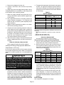
C−Charging
TABLE 4
HS29−072−1, −2, −3 & HS29−090−2 & HS29−120−2 Units
Outdoor Coil
Entering Air
Temperature
HS29−072*
Discharge
+ 10 psig
HS29−072*
Suction
+ 5 psig
HS29−072**
Discharge
+ 10 psig
HS29−072**
Suction
+ 5 psig
HS29−090**
Discharge
+ 10 psig
HS29−090**
Suction
+ 5 psig
HS29−120***
Discharge
+ 10 psig
HS29−120***
Suction
+ 5 psig
65_F (18_C)
173
61
180
73
196
71
181
66
75_F (24_C)
199
63
207
75
224
72
206
68
85_F (29_C)
229
65
238
77
254
73
234
69
95_F (35_C)
261
67
271
79
288
74
265
70
105_F (40_C)
298
71
308
82
323
76
300
72
115_F (46_C)
333
72
342
83
363
77
335
73
*HS29−072 tested with CB30U−65. Pressure shown is with typical 5ton indoor coil matchup.
**HS29−072 and HS29−090 tested with CB17/CBH17−95V.
***HS29−120 tested with CB17/CBH17−135V.
TABLE 5
HS29−090−3 and HS29−120−3 Units
Outdoor Coil
Entering Air
Temperature
HS29−090**
Discharge
+ 10 psig
HS29−090**
Suction
+ 5 psig
HS29−120***
Discharge
+ 10 psig
HS29−120***
Suction
+ 5 psig
65_F (18_C)
189
72
169
63
75_F (24_C)
217
73
197
67
85_F (29_C)
245
75
226
70
95_F (35_C)
278
76
256
71
105_F (40_C)
314
77
290
73
115_F (46_C)
352
79
328
74
**HS29−072 and HS29−090 tested with CB17/CBH17−95V.
***HS29−120 tested with CB17/CBH17−135V.
TABLE 6
HS29−180* Circuit 1
HS29−180* Circuit 2
HS29−240** Circuit 1
HS29−240** Circuit 2
Outdoor Coil
Entering Air
Temperature
Discharge
+ 10 psig
Suction
+ 5 psig
Discharge
+ 10 psig
Suction
+ 5 psig
Discharge
+ 10 psig
Suction
+ 5 psig
Discharge
+ 10 psig
Suction
+ 5 psig
65_F (18_C)
174
62
173
67
190
70
193
68
75_F (24_C)
202
64
200
69
213
71
216
70
85_F (29_C)
231
65
229
70
240
73
245
71
95_F (35_C)
263
67
260
71
272
75
275
73
105_F (40_C)
298
68
294
72
305
76
309
74
115_F (46_C)
336
70
331
73
342
78
346
76
*HS29−180 tested with CB17/CBH17−185V. **HS29−240 tested with CB17/CBH17−275V.
NOTE − System charging is not recommended below 60°F
(15°C). If the temperature is below 60°F (15°C), the charge
must be weighed into the system.
Units are shipped with a holding charge of dry air and
helium which must be removed before the unit is evac
uated and charged with refrigerant. The most accurate
method of charging is to weigh the refrigerant into the unit
as indicated in the following procedure.
Page 20
1 − Recover the refrigerant from the unit.
2 − Conduct a leak check, then evacuate as previously
outlined.
3 − Weigh in the amount of charge listed in tables 2 and 3.
If weighing facilities are not available, or if the charge needs
to be checked, use the following method.
1 − Attach the gauge manifolds and operate the unit in
cooling mode until the system stabilizes (approximate
ly five minutes).
2 − Use a digital thermometer to accurately measure the
outdoor ambient temperature. For HS29−180 and
HS29−240 units, check each system separately with all
stages operating.
3 − Apply the outdoor temperature to table 4 or 6 to deter
mine normal operating pressures.
4 − Compare the normal operating pressures to the pres
sures obtained from the gauges. Minor variations in
these pressures may be expected due to differences in
installations. Significant differences could mean that
the system is not properly charged or that a problem
exists with some component in the system. Correct
any system problems before proceeding.
5 − Add or remove the charge in increments and allow the
system to stabilize each time you add or remove the re
frigerant.
HS29−072, HS29−090, HS29−120 ONLY
Use the approach method to confirm readings.
Verifying the Charge Using Approach Method for
Temperatures > 60°F only
Do not use the approach method if the system pressures
do not match the pressures given in table 4. The approach
method is not valid for grossly over or undercharged sys
tems.
IMPORTANT
Use tables 4, 5 and 6 as a general guide for perform
ing maintenance checks. These tables are not a pro
cedure for charging the system. Minor variations in
these pressures may be expected due to differ
ences in installations. Significant deviations could
mean that the system is not properly charged or that
a problem exists with some component in the sys
tem. Used prudently, these tables could serve as a
useful service guide.
1 − Use the same digital thermometer to take the liquid line
temperature and the outdoor ambient temperature.
Measure the liquid line temperature at the condenser
outlet. Then compare the liquid line temperature to the
outdoor ambient temperature. The approach temper
ature equals the liquid line temperature minus the
outdoor ambient temperature.
Page 21
2 − The approach temperature should match values given
in table 7. An approach temperature greater than the
value shown indicates an undercharge. An approach
temperature that is less than the value shown indicates
an overcharge.
TABLE 7
Approach Method
MODEL NO.
LIQUID TEMP. MINUS
AMBIENT TEMP. °F (°C)
HS29−072−1, −2 , −3*
12 + 1 (6.7 + .5)
HS29−072−1, −2, −3**
16 + 1 (8.9 + .5)
HS29−090−2,**
11 + 1 (6.0 + .5)
HS29−120−2,***
11 + 1 (6.0 + .5)
HS29−090−3**
12 + 1 (6.7 + .5)
HS29−120−3***
9 + 1 (5.0 + .5)
Note − For best results, use the same digital thermometer check
both outdoor ambient and liquid line temperature at the exit of the
condenser.
*Matched with CB30U65 or typical 5ton indoor evaporator
coil.
**Matched with CB17/CBH17−95V.
***Matched with CB17/CBH17−135V.
HS29−180, HS29−240 ONLY
Use subcooling method to confirm readings.
Charge Verification Using the Subcooling Method
1 − Use the same thermometer to take both liquid line
temperature and outdoor ambient temperature.
2 − Note the liquid line pressure and convert the value to
the saturated condensing temperature using a stan
dard HCFC−22 temperature/pressure table or the con
version scale on the gauge.
TABLE 8
Subcooling Values
HS29−180
HS29−240
Outdoor Coil
Entering Air
Temperature
Circuit 1
(± 1°F)
Circuit 2
(± 1°F)
Circuit 1
(± 1°F)
Circuit 2
(± 1°F)
65°F (18°C)
75°F (24°C)
85°F (29°C)
95°F (35°C)
105°F (41°C)
115°F (46°C)
9
10
12
14
17
18
8
9
13
15
17
19
12
13
12
14
15
15
13
13
14
15
16
16
3 − Subtract the liquid line temperature from the saturated
condensing temperature to calculate the subcooling
value. (Saturated condensing temperature − Liquid line
temperature = Subcooling value.) The subcooling val
ue should approximate the corresponding value found
in table 8.
4 − Add refrigerant to increase the subcooling value. Re
move refrigerant to reduce the subcooling value.
Charge adjustments should be done in increments and
the system should be allowed to stabilize between ad
justments.
D−Oil Charge
See compressor nameplate for oil charge.
V−MAINTENANCE
CAUTION
Electrical shock hazard. Turn off power to unit be
fore performing any maintenance, cleaning or ser
vice operation on the unit.
IMPORTANT
If insufficient cooling occurs, the unit should be
gauged and refrigerant charge checked.
B−Indoor Unit
At the beginning of each heating or cooling season, the
system should be cleaned as follows:
1 − Clean or change filter if necessary.
A−Outdoor Unit
3 − Check connecting lines and coil for leaks.
1 − Clean and inspect condenser coil (Coil may be flushed
with water hose).
4 − Check condensate line and clean if necessary.
2 − Clean coil if necessary.
5 − Adjust blower speed for cooling. The pressure drop
2 − Visually inspect all connecting lines, joints and coils for
evidence of oil leaks.
over the coil should be measured to determine the cor
3 − Condenser fan motor is prelubricated and sealed. No
further lubrication is needed.
manual for pressure drop tables and procedure.
4 − Check wiring for loose connections.
5 − Check for correct voltage at unit (unit operating).
6 − Check amp−draw of condenser fan motor (s).
Unit nameplate
Actual
.
Unit nameplate
Actual
.
Unit nameplate
Actual
.
Unit nameplate
Actual
.
rect blower CFM. Refer to unit information service
6 − On belt drive blowers, check belt for wear and proper
tension. Check pulleys for wear. Anything less than a
true "V" should be replaced.
7 − Check wiring for loose connections.
8 − Check for correct voltage at unit (unit operating).
9 − Check amp−draw on blower motor
Unit nameplate
Page 22
Actual
.
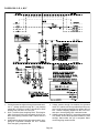
VI−Wiring Diagram and Sequence of Operation
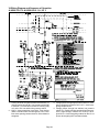
A−HS29−072−1/−2 & HS29−090−2 −G, J, M, Y
1 − Cooling demand energizes at thermostat terminal Y1.
Voltage passes through N.C. low pressure switch S87
to terminal 1 on timer DL33, and K167 latching relay
coil, and to S11 low ambient low pressure switch.
2 − K167−1 closes energizing timer DL33. Timer begins.
(After 5 minutes DL33 is de−energized). K167−2 con
tacts close opening contacts 9 and 3. Indoor blower is
energized.
Page 23
3 − Voltage passes through high pressure switch S4, ener
gizing compressor contactor coil K1. K1−1 closes ener
gizing compressor B1.
4 − Voltage passes through low ambient low pressure
switch S11. (Switch will close provided liquid line pres
sure is high enough). Outdoor fan coil K10 is ener
gized. K10−1 closes energizing outdoor fan B4. K10−2
opens de−energizing HR1 crankcase heater.
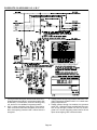
B−HS29−072−3 & HS29−090−3 −G, J, M, Y
1 − Cooling demand energizes at thermostat terminal Y1.
Voltage passes through N.C. low pressure switch S87
to terminal 1 on timer DL33, and K167 latching relay
coil, and to S11 low ambient low pressure switch.
2 − K167−1 closes energizing timer DL33. Timer begins.
(After 5 minutes DL33 is de−energized). K167−2 con
tacts close opening contacts 9 and 3. Indoor blower is
energized.
3 − Voltage passes through high pressure switch S4, ener
gizing compressor contactor coil K1. K1−1 closes ener
gizing compressor B1.
4 − Voltage passes through low ambient low pressure
switch S11. (Switch will close provided liquid line pres
sure is high enough). Outdoor fan coil K10 is ener
gized. K10−1 closes energizing outdoor fan B4. K10−2
opens de−energizing HR1 crankcase heater.
Page 24
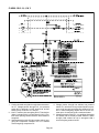
C−HS29−120−2 −G, J, M, Y
1 − Cooling demand energizes through thermostat termi
nal Y1. Voltage passes through N.C. low pressure
switch S87, to terminal 1 on N.O. timer DL33, to K167
latching relay coil and to S11 and S41.
2 − K167−1 contacts close energizing DL33. Timer begins.
(After 5 minutes DL33 is de−energized.) K167−2 con
tacts close opening contacts 9 and 3. Indoor blower is
energized.
3 − Voltage passes through S4 high pressure switch, ener
gizing K1 compressor contactor coil. K1−1 contacts
close energizing compressor B1.
Page 25
4 − Voltage passes through low ambient low pressure
switch S11 (switch will close provided liquid line pres
sure is high enough) energizing K10 outdoor fan coil.
K10−1 closes energizing outdoor fan B4. K10−2 con
tacts open, de−energizing HR1 crankcase heater.
5 − Voltage passes through N.C. low ambient thermostat
S41 (switch will be closed provided ambient is warm
enough). K68 outdoor fan coil is energized. K68−1
close energizing outdoor fan B5.
D−HS29−120−3 −G, J, M, Y
1 − Cooling demand energizes through thermostat termi
nal Y1. Voltage passes through N.C. low pressure
switch S87, to terminal 1 on N.O. timer DL33, to K167
latching relay coil and to S11 and S41.
2 − K167−1 contacts close energizing DL33. Timer begins.
(After 5 minutes DL33 is de−energized.) K167−2 con
tacts close opening contacts 9 and 3. Indoor blower is
energized.
3 − Voltage passes through S4 high pressure switch, ener
gizing K1 compressor contactor coil. K1−1 contacts
close energizing compressor B1.
4 − Voltage passes through low ambient low pressure
switch S11 (switch will close provided liquid line pres
sure is high enough) energizing K10 outdoor fan coil.
K10−1 closes energizing outdoor fan B4. K10−2 con
tacts open, de−energizing HR1 crankcase heater.
5 − Voltage passes through N.C. low ambient thermostat
S41 (switch will be closed provided ambient is warm
enough). K68 outdoor fan coil is energized. K68−1
close energizing outdoor fan B5.
Page 26
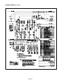
E−HS29−180/240 −G, J, M, Y
Page 27
HS29−180/240
1−
2−
3−
4−
5−
6−
7−
8−
9−
First stage cool
Cooling demand energizes K66 relay coil at thermostat
terminal Y1.
K66−1 contacts close, voltage passes through S87 low
pressure switch to terminal 1 on DL33 timer to K167
latching relay coil.
K167−1 contacts close energizing DL33. Timer begins.
(After 5 minutes DL33 is de−energized)
Voltage passes through S4 high pressure limit energiz
ing K1 compressor contactor. K1−1 contacts close en
ergizing compressor B1.
K167−2 contacts close. Contacts 8 and 2 open energiz
ing indoor blower.
K167−3 contacts close sending voltage to K58 low am
bient contact terminal 4.
K66−2 contacts close. Voltage passes through S11 low
ambient pressure switch (switch will be closed pro
vided liquid line pressure is high enough) to K10 out
door fan relay coil.
K10−1 contacts close energizing outdoor fan B4. K10−2
contacts open de−energizing HR1crankcase heater.
K66−3 contacts close sending voltage through low am
bient limit switch S41 (switch will close provided ambi
ent is warm enough) to K58 low ambient coil. K58−1
closes energizing K68 outdoor fan coil. K68−1 contacts
close energizing outdoor fan B5.
Second stage cool
10− Cooling demand energizes K67 relay coil at thermostat
terminal Y2.
11− K67−1 contacts close, voltage passes through S88 low
pressure switch to terminal 1 on DL34 timer to K168
latching relay coil.
12− K168−1 contacts close energizing DL34. Timer begins.
(After 5 minutes DL34 is de−energized)
13− Voltage passes through S7 high pressure switch ener
gizing K2 compressor contactor coil. K2−1 contacts
close energizing compressor B2.
14− K168−2 contacts close. Contacts 8 and 2 open energiz
ing indoor blower.
15− K168−3 contacts close sending voltage to K58 low am
bient contact terminal 6.
16− K67−2 contacts close. Voltage passes through S84 low
ambient pressure switch (switch will close provided liq
uid line pressure is warm enough) to outdoor fan relay
coil K149.
17− K149−1 contacts close energizing outdoor fan B21.
K149−2 contacts close de−energizing HR2 crankcase
heater.
18− K67−3 contacts close sending voltage through S41 low
ambient limit (switch will closed provided ambient is
high enough) to low ambient relay coil K58. K58−2 con
tacts close energizing K150 outdoor fan relay coil.
K150−1 contacts close energizing B22 outdoor fan.
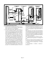
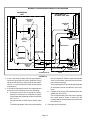
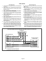
HS29 FIELD WIRING WITH BLOWER COIL UNIT AND AUXILIARY ELECTRIC HEAT
THERMOSTAT
Y1
Y2
G
R
W1
HS29 CONDENSING UNIT
1
YELLOW
Y1
BLUE
Y2
GREEN
G
GREEN
G1
CB17/CBH17 WITH EH17
ELECTRIC HEAT
G (FAN)
GREEN
W1 (HEAT) WHITE
1
RED
24V−R
R (24VAC)
GRAY
24V−C
C (COMMON)BLACK
"G" WIRE MUST BE ROUTED FROM THERMOSTAT
TO CONDENSING UNIT AS SHOWN, TO PROVIDE
BLOWER INTERLOCK WITH THE COMPRESSOR.
Page 28
BLUE