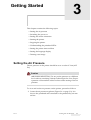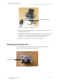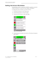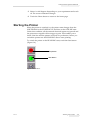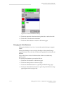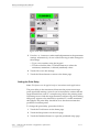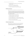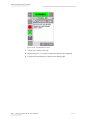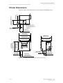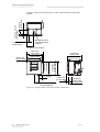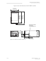
1
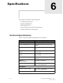
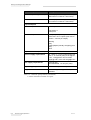
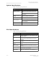
Videojet 6210
Operator Manual
P/N 361853-21
Revision: AA, November 2006
Copyright 2006, Videojet Technologies Inc. (herein referred to as Videojet). All rights reserved.
This document is the property of Videojet Technologies Inc.and contains confidential and
proprietary information owned by Videojet Any unauthorized copying, use or disclosure of it
without the prior written permission of Videojet is strictly prohibited.
Videojet Technologies Inc.
1500 Mittel Boulevard
Wood Dale, IL
60191-1073 USA
www.videojet.com
Phone: 1-800-843-3610
Fax:
1-800-582-1343
Int’l Fax: 630-616-3629
Offices - USA: Atlanta, Chicago
Int’l: Canada, France, Germany, Ireland, Japan, Spain,
Singapore, Netherlands, and United Kingdom
Distributors Worldwide
Compliance Information
For Customers in U.S.A.
This device complies with Part 15 of the FCC Rules. Operation is
subject to the following two conditions: 1) this device may not cause
harmful interference, and 2) this device must accept any interference
received, including the interference that may cause undesired
operation.
Warning
Changes or modifications to this unit not expressly approved by
the party responsible for compliance could void the user’s
authority to operate the equipment.
This equipment has been tested and found to comply with the limits
for a Class A digital device, pursuant to Part 15 of the FCC Rules.
These limits are designed to provide responsible protection against
harmful interference when the equipment is operated in a commercial
environment. This equipment generates, uses, and can radiate radio
frequency energy and, if not installed and used in accordance with the
instruction manual, may cause harmful interference to radio
communications. Operation of this equipment in a residential area is
likely to cause harmful interference. In such cases, the users will be
required to correct the interference at their own expense.
Shielded cables must be used with this unit to ensure compliance with
Class A FCC limits.
The user may find the following booklet prepared by the Federal
Communications Commission helpful: How to Identify and Resolve
Radio-TV Interference Problems. This booklet is available from the
U.S. Government Printing Office, Washington, DC 20402, Stock No.
004-00-00345-4. This equipment has been tested and certified for
compliance with U.S. regulations regarding safety and electrical
emissions by TRL Laboratories of UK.
For Customers in Canada
This digital apparatus does not exceed the Class A limits for radio
noise emissions from digital apparatus set out in the Radio
Interference Regulations of the Canadian Department of
Communications.
This equipment has been tested and certified for compliance with
Canadian regulations regarding safety and electrical emissions by TRL
Laboratories of UK.
Rev AA
i
Videojet 6210 Operator Manual
Pour la Clientèle du Canada
Le present appareil numerique n’emet pas de bruits radioelectriques
depassant les limites applicales aux appareils numerique de las class A
prescrites dans le Reglement sur le brouillage radioelectrique edicte
par le ministere des Communications du Canada.
Cet équipement est certifié CSA.
For Customers in the European Union
This equipment displays the CE mark to indicate conformance to the
following legislation.
EN55022:1998
EN55024:1998
EN61000-6-2:2001
FCC CFR 47 parts 15.107 and 15.109
ii
Rev AA
Support and Training
Contact Information
If you have any questions or need assistance, please contact Videojet
Technologies Inc. at 1-800-843-3610 (for all customers within the
United States). Outside the U.S., customers should contact their
Videojet Technologies Inc. distributor or subsidiary for assistance.
Videojet Technologies Inc.
1500 Mittel Boulevard
Wood Dale, IL 60191-1073 U.S.A.
Phone: 1-800-843-3610
Fax: 1-800-582-1343
International Fax: 630-616-3629
Web: www.videojet.com
Service Program
About Total Source Commitment
Total Source® TOTAL SERVICE PLUS RELIABILITY, is the Videojet
Technologies Inc. commitment to provide you - our customer - the
complete service you deserve.
The Total Source Commitment
The Videojet Total Source® Service Program is an integral part of our
business in providing marks, codes, and images where, when, and
how often customers specify for packages, products, or printed
materials. Our commitment includes:
• Applications support
• Installation services
• Maintenance training
• Customer response center
• Technical support
• Field service
• Extended hours phone assistance
• Parts and supplies
• Repair service
Rev AA
iii
Videojet 6210 Operator Manual
Customer Training
If you wish to perform your own service and maintenance on the
printer, Videojet Technologies Inc. highly recommends you to
complete a Customer Training Course on the printer.
Note: The manuals are intended to be supplements to (and not replacements
for) Videojet Technologies Inc. Customer Training.
For more information on Videojet Technologies Inc. Customer
Training Courses, call 1-800-843-3610 (within the United States only).
Outside the U.S., customer should contact a Videojet subsidiary office
or their local Videojet distributor for more information.
iv
Rev AA
Table of Contents
Compliance Information
For Customers in U.S.A.. . . . . . . . . . . . . . . . . . . . . . . . . . . . . . . . . . . . . . . i
For Customers in Canada . . . . . . . . . . . . . . . . . . . . . . . . . . . . . . . . . . . . . . i
Pour la Clientèle du Canada . . . . . . . . . . . . . . . . . . . . . . . . . . . . . . . . . . . . ii
For Customers in the European Union . . . . . . . . . . . . . . . . . . . . . . . . . . . . ii
Support and Training
Contact Information . . . . . . . . . . . . . . . . . . . . . . . . . . . . . . . . . . . . . . . . . iii
Service Program . . . . . . . . . . . . . . . . . . . . . . . . . . . . . . . . . . . . . . . . . . . . iii
Customer Training . . . . . . . . . . . . . . . . . . . . . . . . . . . . . . . . . . . . . . . . . . iv
Chapter 1 — Safety
Introduction. . . . . . . . . . . . . . . . . . . . . . . . . . . . . . . . . . . . . . . . . . . . . . . . 1–1
Safety Conventions Used in the Manual. . . . . . . . . . . . . . . . . . . . . . . . 1–2
General Warning Notices . . . . . . . . . . . . . . . . . . . . . . . . . . . . . . . . . 1–2
General Caution Notices. . . . . . . . . . . . . . . . . . . . . . . . . . . . . . . . . . 1–3
Safety Guidelines . . . . . . . . . . . . . . . . . . . . . . . . . . . . . . . . . . . . . . . . . . . 1–4
Comply with Electrical Codes . . . . . . . . . . . . . . . . . . . . . . . . . . . . . 1–4
Do Not Remove Warning Labels. . . . . . . . . . . . . . . . . . . . . . . . . . . 1–4
Placement of the Printer . . . . . . . . . . . . . . . . . . . . . . . . . . . . . . . . . . . . . 1–5
Using Printer Accessories . . . . . . . . . . . . . . . . . . . . . . . . . . . . . . . . . 1–5
Chapter 2 — Introduction
Equipment Description . . . . . . . . . . . . . . . . . . . . . . . . . . . . . . . . . . . . . . 2–1
About this Manual . . . . . . . . . . . . . . . . . . . . . . . . . . . . . . . . . . . . . . . . . . 2–2
Related Documents . . . . . . . . . . . . . . . . . . . . . . . . . . . . . . . . . . . . . . 2–2
Overview of Printer Parts . . . . . . . . . . . . . . . . . . . . . . . . . . . . . . . . . . . . 2–3
About the CLARiTY Operating System . . . . . . . . . . . . . . . . . . . . . . . . 2–4
Creating and Adding New Jobs . . . . . . . . . . . . . . . . . . . . . . . . . . . . . . . 2–7
Chapter 3 — Getting Started
Setting the Air Pressure . . . . . . . . . . . . . . . . . . . . . . . . . . . . . . . . . . . . . . 3–1
Switching the Power On . . . . . . . . . . . . . . . . . . . . . . . . . . . . . . . . . . . . . 3–2
Setting the Screen Orientation . . . . . . . . . . . . . . . . . . . . . . . . . . . . . . . . 3–4
Starting the Printer . . . . . . . . . . . . . . . . . . . . . . . . . . . . . . . . . . . . . . . . . . 3–5
Stopping the Printer . . . . . . . . . . . . . . . . . . . . . . . . . . . . . . . . . . . . . . . . . 3–6
Setting the Time and Date . . . . . . . . . . . . . . . . . . . . . . . . . . . . . . . . . . . . 3–6
Setting the Language and Region Display . . . . . . . . . . . . . . . . . . . . . . 3–8
Printing a Test Image . . . . . . . . . . . . . . . . . . . . . . . . . . . . . . . . . . . . . . . . 3–9
Rev AA
i
Videojet 6210 Operator Manual
Chapter 4 — Viewing and Selecting a New Print Job
Viewing the Current Job or Image . . . . . . . . . . . . . . . . . . . . . . . . . . . . . 4–1
Selecting a New Job . . . . . . . . . . . . . . . . . . . . . . . . . . . . . . . . . . . . . . . . . 4–3
Changing Variable Information . . . . . . . . . . . . . . . . . . . . . . . . . . . . . . . 4–5
Changing Variable Text Information. . . . . . . . . . . . . . . . . . . . . . . . 4–5
Changing Variable Date Information . . . . . . . . . . . . . . . . . . . . . . 4–10
Changing the Position or Appearance of the Print . . . . . . . . . . . . . . 4–12
Changing the Print Position . . . . . . . . . . . . . . . . . . . . . . . . . . . . . . 4–13
Changing the Print Orientation . . . . . . . . . . . . . . . . . . . . . . . . . . . 4–14
Changing the Print Darkness . . . . . . . . . . . . . . . . . . . . . . . . . . . . . 4–15
Setting the Print Delay. . . . . . . . . . . . . . . . . . . . . . . . . . . . . . . . . . . 4–16
Setting the Print Speed. . . . . . . . . . . . . . . . . . . . . . . . . . . . . . . . . . . 4–17
Setting the Printhead Position . . . . . . . . . . . . . . . . . . . . . . . . . . . . 4–17
Setting Interleaved Images . . . . . . . . . . . . . . . . . . . . . . . . . . . . . . . 4–18
Deleting a Job from the Jobs Database. . . . . . . . . . . . . . . . . . . . . . . . . 4–19
Chapter 5 — Routine Fault Finding and Maintenance
Working with Fault Messages and Warnings. . . . . . . . . . . . . . . . . . . . 5–1
Reading a Fault Message or Warning . . . . . . . . . . . . . . . . . . . . . . . 5–1
Clearing a Fault Message or Warning . . . . . . . . . . . . . . . . . . . . . . . 5–2
Removing and Reinstalling the Cassette . . . . . . . . . . . . . . . . . . . . . . . . 5–4
Checking and Replacing the Ribbon . . . . . . . . . . . . . . . . . . . . . . . . . . . 5–7
Checking the Printer Ribbon Supply. . . . . . . . . . . . . . . . . . . . . . . . 5–7
Replacing the Ribbon . . . . . . . . . . . . . . . . . . . . . . . . . . . . . . . . . . . . . 5–7
Using Ribbons of Different Widths and Colors . . . . . . . . . . . . . . . . . 5–11
Viewing the Printer Performance Statistics. . . . . . . . . . . . . . . . . . . . . 5–12
Cleaning the Printhead. . . . . . . . . . . . . . . . . . . . . . . . . . . . . . . . . . . . . . 5–13
Chapter 6 — Specifications
Technical Specifications . . . . . . . . . . . . . . . . . . . . . . . . . . . . . . . . . . . . . . 6–1
System Specifications . . . . . . . . . . . . . . . . . . . . . . . . . . . . . . . . . . . . . . . . 6–3
Print Specifications . . . . . . . . . . . . . . . . . . . . . . . . . . . . . . . . . . . . . . . . . . 6–3
External Communications . . . . . . . . . . . . . . . . . . . . . . . . . . . . . . . . . . . . 6–4
Printer Dimensions . . . . . . . . . . . . . . . . . . . . . . . . . . . . . . . . . . . . . . . . . . 6–5
ii
Rev AA
1
Safety
This chapter contains the following topics:
• Safety conventions used throughout this manual
• Important safety guidelines to be followed when operating the
equipment
Warning
PERSONAL INJURY. Read this chapter thoroughly before
attempting to install, operate, service, or maintain this product
otherwise, it may cause serious injury.
Introduction
The policy of Videojet Technologies Inc. is to manufacture printing/
coding systems and supplies that meet high standards of performance
and reliability. Therefore, we employ strict quality control measures to
eliminate the potential for defects and hazards in our products.
The intended use of this printer is to print information directly onto a
product. Use of this equipment for any other purpose may lead to
serious personal injury.
The safety guidelines provided in this chapter are intended to educate
the operator on all safety issues so that the operator can operate the
printer safely.
Rev AA
Introduction
1-1
Videojet 6210 Operator Manual
Safety Conventions Used in the Manual
Specific safety information is listed throughout this manual in the
form of Warning and Caution statements. Pay close attention to these
statements as they contain important information that help in
avoiding potential hazards to yourself or to the equipment.
General Warning Notices
The following warnings supplement the specific warnings that appear
elsewhere in the manual. These are general warnings that must be
read, completely understood, and applied by all the personnel
involved in the operation, and/or the maintenance of the machine.
Warning
PERSONAL INJURY. Only trained service or maintenance
personnel should perform these installation procedures.
Qualified personnel have successfully completed the training
courses, have sufficient experience with this printer, and are
aware of the potential hazards to which they will be exposed.
Warning
PERSONAL INJURY. Before attempting any maintenance or
repair on any part of the product, disconnect the printer from the
main power supply and isolate the printer from any external
energy sources including other connected equipment.
Warning
PERSONAL INJURY. Before connecting the compressed air
supply to the printer, ensure that the air supply has been
isolated. Turn the regulator adjustment knob counterclockwise.
Warning
PERSONAL INJURY. The printer uses an operator control
console. Ensure that this panel is mounted at an appropriate
working height and orientation for ease of operation.
1-2
Safety Conventions Used in the Manual
Rev AA
Videojet 6210 Operator Manual
Warning
PERSONAL INJURY. Keep your hands and clothing clear of the
printer while it is on.
Warning
PERSONAL INJURY. To ensure that the connecting cables and
pipes do not become a trip hazard or become entangled in any
machinery, all the connecting cables and pipes must be secured
safely during installation.
Warning
ELECTRICAL HAZARD. Voltages used to connect the printer to
other equipment must not be greater than 50 V dc or peak ac.
Warning
ELECTRICAL HAZARD. Always wear a properly grounded
wrist-ground strap when handling printed circuit boards.
Failure to do so can result in damage to the board components
due to static electricity.
General Caution Notices
The following caution statements supplement the specific cautions
that appear elsewhere in the manual. These are general cautions which
must be read, completely understood, and applied by all the personnel
involved with the operation, and/or the maintenance of the machine.
Caution
EQUIPMENT DAMAGE. Before and after performing any
maintenance or repair on the product, check that the two safety
labels are clearly visible. One is on the power supply cover and
the other by the potential nip point next to the pulley in the
printer body.
Rev AA
Safety Conventions Used in the Manual
1-3
Videojet 6210 Operator Manual
Caution
EQUIPMENT DAMAGE. The use of incompatible ribbon can
seriously damage your printer and such damage will not be
covered by your printer warranty. Use only the ribbon approved
by your dealer.
Safety Guidelines
This section contains important safety guidelines on operating and
handling the printer and associated equipment.
Warning
PERSONAL INJURY. Always observe the following safety
guidelines when operating and handling the printer and
associated equipment otherwise, it may cause serious injury.
Comply with Electrical Codes
All electrical wiring and connections must comply
with applicable local codes. Consult the appropriate
regulatory agency for further information.
Do Not Remove Warning Labels
Do not, under any circumstances, remove or obstruct
any warning or instruction labels on the printer.
1-4
Safety Guidelines
Rev AA
Videojet 6210 Operator Manual
Placement of the Printer
Warning
PERSONAL INJURY. Do not place the printer in a hazardous
location. Hazardous locations might create an explosion, leading
to personal injury.
Hazardous locations, as defined in the United States, are those areas
that may contain hazardous materials in a quantity sufficient to create
an explosion. These are defined in Article 500 of the National Electrical
Code ANSI/NFPA 70–1993.
Outside United States, you must ensure compliance with all local
regulations regarding the equipment placement in potentially
hazardous locations.
Using Printer Accessories
To maintain regulatory approval for the printer, use only Videojet
approved accessories when attaching any device to the equipment.
Rev AA
Placement of the Printer
1-5
2
Introduction
This chapter contains the following topics:
• Description about the intended use of the product
• Information contained in this manual and other manuals
associated with this printer
• Description of the CLARiTY™ operating system
• Information on creating and adding new jobs
Warning
PERSONAL INJURY. Read Chapter 1, “Safety” before
attempting to operate the equipment otherwise, it may cause
serious injury.
Equipment Description
The Videojet 6210 printer uses high-resolution thermal transfer
technology with a unique electronic ribbon drive system. This system
reduces the wear on printer parts and the maintenance adjustments
normally associated with thermal transfer coders that use mechanical
ribbon drives. The printer offers greater reliability and ease of
operation compared to earlier systems. It can print dates and text onto
flexible packaging films and labels.
The printer is a suitable replacement for either hot stamp or rotary
coders. It can print in either of the following modes:
• Intermittent Mode (i.e., while the substrate is stationary)
• Continuous Mode (i.e., while the substrate is moving)
It is suitable for use on most horizontal form/fill/seal, vertical
form/fill/seal, and self-adhesive labelling machines.
The product is available in either left-handed or right-handed versions
to suit different configurations of the packaging machine.
Rev AA
Equipment Description
2-1
Videojet 6210 Operator Manual
About this Manual
This manual is intended for the operator and contains information on
the routine operation of the printer, including routine cleaning and
maintenance tasks. Unless noted otherwise, all procedures in this
manual can be performed by the operator of the printer.
Note: Installation and service procedures are described in the service manual
(refer “Related Documents” on page 2-2).
This manual is a supplement to (and not a replacement for) formal
training.
Related Documents
The Videojet 6210 Service Manual (P/N 361854) is the other document
that is available (through Videojet Customer Service), for this printer.
The service manual contains information on installing, maintaining,
troubleshooting, and servicing this printer. It also includes sections
about the theory of operation, component identification, and the
illustrated parts breakdown of the printer.
This Videojet 6210 Service Manual is intended for use only by trained
service personnel. The service manual is a supplement to (and not a
replacement for) formal training.
Warning
PERSONAL INJURY. Customers who intend to service and
maintain the printer themselves must have only qualified
personnel perform these procedures. Qualified personnel have
successfully completed the training courses, have sufficient
experience with this printer, and are aware of the potential
hazards to which they will be exposed.
2-2
About this Manual
Rev AA
Videojet 6210 Operator Manual
Overview of Printer Parts
The main parts of the Videojet 6210 printer is described as follows:
• CLARiTY Controller: Houses the power supply unit and touch
screen. You can access jobs, setup jobs, set the various print
parameters using the touch screen
• Printer: Houses the printhead and ribbon. The data is transferred
to the printhead from the CLARiTY controller. The printhead
prints onto the packaging film.
1
2
9
3
4
8
5
7
1. Air Regulator
2. 4 mm Air Tubing
3. CLARiTY Controller
4. CLARiTY Controller Bracket
5. Power Cable
6
6. Printer
7. Low Profile Cable Assembly
8. Cassette
9. CLARiTY Configuration Manager CDROM
Figure 2-1: Printer Configuration Parts
Rev AA
Overview of Printer Parts
2-3
Videojet 6210 Operator Manual
About the CLARiTY Operating System
CLARiTY is an icon-based operator control system. It has an easy-touse touch screen and most areas of the display are "active", that is,
simply touching an area of the screen is like pressing a "button" on a
traditional control panel. The CLARiTY home screen’s main buttons
are shown in Figure 2-2.
1
2
5
3
4
1. Machine Status Button
2. Tools Button
3. Current Job Details Button
4. Control Frame Buttons
5. Home Button
Figure 2-2: CLARiTY Home Screen
Shortcut buttons take you directly to the key pages, regardless of the
page that you are currently viewing.
Table 2-1 provides the list of shortcut buttons to be used to access the
required pages.
Buttons
Display
Tools Page for printer set
up and diagnostics
Home Page
Fault and Warning Pages
Table 2-1: List of Shortcut Buttons
2-4
About the CLARiTY Operating System
Rev AA
Videojet 6210 Operator Manual
Table 2-2 shows the buttons used to select a new job or view the
current job selected.
Buttons
Display
Job Page (to load the next
image or job to be printed,
and to enter any variable
data)
Current Job (shown as the
Current Job Name)
Table 2-2: Buttons for Viewing Jobs
The navigation bar (Figure 2-3) indicates the location of the current
page in the menu tree. To use the navigation bar, do one of the
following:
• Touch the Back button to go back to the previous page.
• Touch any title on the navigation bar to go to that page directly.
2
1
1. Back Button
2. Navigation Bar
Figure 2-3: Navigation Bar
Rev AA
About the CLARiTY Operating System
2-5
Videojet 6210 Operator Manual
On the left side of the home screen display is the Control Frame
(Figure 2-2 on page 2-4). This contains buttons (Table 2-3) that stay
active as long as the printer is powered up. These buttons are used for
the immediate control of your printer.
Button
Description
Stop
Start
Test Print
Print Registration
Table 2-3: Control Frame Buttons
The home screen contains two more buttons (Figure 2-4 on page 2-7):
• Production Performance button
• Consumables Status button
2-6
About the CLARiTY Operating System
Rev AA
Videojet 6210 Operator Manual
Touch each of these areas to go to the pages that contain further details
and statistics about production throughput and ribbon status.
1
2
1. Production Performance Button
2. Consumables Status Button
Figure 2-4: Performance and Consumables Status Buttons
Creating and Adding New Jobs
Print jobs are created offline using the CLARiSOFT™ image design
software that runs on a PC.
This is a What You See Is What You Get (WYSIWYG) package that
enables you to design the look and feel of a print image and define the
content of special fields such as complex sell by date calculations.
When the job has been designed using CLARiSOFT, it is saved with a
unique job name onto the PC's disc. Jobs are transferred into the
Videojet 6210 local database by connecting the PC to the printer using
an RS232 cable.
Alternatively, the Videojet 6210 printer has the ability to download a
'Job' database directly from a USB device. Jobs can now be created in
CLARiSOFT and saved onto a USB device, ready for directly
downloading into the printer. This removes the need to take a lap top
into the production area.
For information on how to create images, refer the online help
supplied with CLARiSOFT. For more information on how to transfer
images to the printer, refer the Videojet 6210 Service Manual.
Rev AA
Creating and Adding New Jobs
2-7
Videojet 6210 Operator Manual
Once the jobs are stored in the printer’s local database, the PC may be
removed. Jobs are then selected for printing as described in “Selecting
a New Job” on page 4-3.
The printer is supplied with two standard (default) job images:
• Default 4 Line Text
• Default Date Code
You can change the details in these two job images to suit your own
needs. Refer Chapter 4, “Viewing and Selecting a New Print Job” for
instructions on how to change an image.
Variable information such as batch codes or sell by dates can be
entered by using a mobile phone style keypad described in “Changing
Variable Information” on page 4-5.
2-8
Creating and Adding New Jobs
Rev AA
Getting Started
3
This chapter contains the following topics:
• Setting the air pressure
• Switching the power on
• Setting the screen orientation
• Starting the printer
• Stopping the printer
• Understanding the printhead LEDs
• Setting the printer time and date
• Setting the language display
• Printing a test image
Setting the Air Pressure
The air pressure on the printer should be set to a value of 3 bar (43.5
Psi).
Caution
AIR PRESSURE SETTING. Do not set the pressure to a different
level without consulting Videojet Technologies Inc. first. Proper
operation of the machine relies on the accurate setting of the air
pressure.
To view and set the air pressure on the printer, proceed as follows:
1 Locate the air pressure regulator (Figure 3-1 on page 3-2). It is
close to the printhead and connected to the printhead by a 4 mm
air line.
Rev AA
Setting the Air Pressure
3-1
Videojet 6210 Operator Manual
Air Pressure Regulator
Figure 3-1: Air Pressure Regulator
2 Read the air pressure displayed on the regulator. It should show a
value of 3 bar (43.5 Psi).
3 If the dial on the regulator does not display the correct value, lift the
air regulator control knob and turn it clockwise to increase the
pressure, or counterclockwise to decrease the pressure.
4 Push the control knob down to lock it in position.
Switching the Power On
To switch the printer on, turn the power switch on the CLARiTY
controller to the I (On) position (Figure 3-2).
Power Switch
Figure 3-2: Printer Power Switch
3-2
Switching the Power On
Rev AA
Videojet 6210 Operator Manual
The boot-up will take approximately 90 seconds. During which a
"starting CLARiTY …" message appears. Following this, the CLARiTY
home page (Figure 3-3) is displayed.
An initialization process of 15 seconds begins, during which the
printer calibrates the ribbon drive. The status bar flashes the words
STARTING UP and the amber LED flashes on and off. When the
process is complete, the home page changes, as follows:
• The CLARiTY status panel changes from STARTING UP to
OFFLINE.
• The Consumables area displays the percentage of ribbon
remaining.
• In the Control Frame, the Start and Stop buttons are enabled.
Figure 3-3 displays the CLARiTY home page in the OFFLINE state.
Figure 3-3: CLARiTY Home Page in the Offline State
Rev AA
Switching the Power On
3-3
Videojet 6210 Operator Manual
Setting the Screen Orientation
Depending the position in which the CLARiTY controller is mounted,
it may be necessary to rotate the screen image by 180 degrees.
To change the screen orientation, proceed as follows:
1 Touch the Tools button on the home page.
2 Touch the Setup button on the tools page.
3 Touch the Control button on the setup page.
Figure 3-4: Control Page
4 Touch Set Screen Orientation from the list. The Screen Orientation
page appears.
Figure 3-5: Screen Orientation
3-4
Setting the Screen Orientation
Rev AA
Videojet 6210 Operator Manual
5 Select 0 or 180 degrees depending on your requirement and touch
ok. The screen orientation changes.
6 Touch the Home button to return to the home page.
Starting the Printer
When the printer is switched on, the printer state changes from the
SHUTDOWN to the STARTING UP and then to the OFFLINE state.
Under this condition, all the external electrical inputs are ignored and
the print sensor signals will not trigger a print. This enables you to
check if the line and the printer are ready for production, before you
switch the printer into the RUNNING state to start printing.
To switch the printer to the RUNNING state, touch the Start button
(Figure 3-6).
Stop Button
Start Button
Figure 3-6: Buttons
Rev AA
Starting the Printer
3-5
Videojet 6210 Operator Manual
Figure 3-7 displays the CLARiTY home page with the printer in the
RUNNING state.
Figure 3-7: CLARiTY Home Page in the Running State
Note: If the printer has a fault or a warning, RUNNING will be replaced
with FAULT or WARNING. If FAULT is displayed, you must fix the
problem before trying to print. Refer “Clearing a Fault Message or Warning”
on page 5-2 for further information.
Stopping the Printer
To stop the printer from printing, touch the red Stop button (Figure 36 on page 3-5). The printer returns to the OFFLINE state.
Setting the Time and Date
To set the time and date in the CLARiTY system, proceed as follows:
1 Touch the Tools button on the home page.
2 Touch the Setup button on the tools page.
3 Touch the Control button.
4 Touch and select Date and Time from the list.
5 Touch Date to set the Date, and the calendar page will appear, as
shown in Figure 3-8 on page 3-7.
3-6
Stopping the Printer
Rev AA
Videojet 6210 Operator Manual
Figure 3-8: System Date Setup
6 Select the current month and year using the + and – keys.
7 Touch today's date to select it.
8 Touch OK to save the settings.
9 Touch Time to set the time. The time set page appears, as shown in
Figure 3-9.
Figure 3-9: CLARiTY System Time Setup
10 Use the + and – keys to give a value for each of the settings [Hours,
Minutes and (optionally) Seconds].
11 Touch OK to save the settings.
Rev AA
Setting the Time and Date
3-7
Videojet 6210 Operator Manual
12 Touch the Home button to return to the home page.
Setting the Language and Region Display
To set the language displayed by CLARiTY, proceed as follows:
1 Touch the Tools button on the home page.
2 Touch the Setup button on the tools page.
3 Touch the Control button.
4 Touch and select Internationalization from the list. The current
language and region is displayed as shown in Figure 3-10.
Figure 3-10: Language and Region
3-8
Setting the Language and Region Display
Rev AA
Videojet 6210 Operator Manual
5 Touch the Region button. A list of available regions is displayed
(Figure 3-11).
Figure 3-11: Region / Country List
6 Touch to select your region from the list (all the currently available
regions will be listed) and touch OK.
7 Touch the Language button. A list of available languages is
displayed
8 Touch to select your language from the list (all the currently
available languages will be listed) and touch OK.
9 Touch the Home button to return to the home page.
The date format displayed in the home page changes according to
the region selected.
Printing a Test Image
Typically, the Videojet 6210 printer is used on a packaging machine
where the print is triggered by a sensor or a Programmable Logic
Controller (PLC).
A test image can be printed before running the printer to check if the
printed image is of acceptable quality. The Test Print button (Figure 312 on page 3-10), will appear greyed out if this feature has been
disabled by the installation engineer. Also, the printer must be set to
Rev AA
Printing a Test Image
3-9
Videojet 6210 Operator Manual
the RUNNING state for the Test Print button to be available.
Test Print
Button
Figure 3-12: Test Print Button
To perform a test print, proceed as follows:
1 If the printer is in the OFFLINE state, press the Start button to put
the printer in the RUNNING state.
2 Ensure that the packaging film is placed under the printhead, if
the printer is in an intermittent application, otherwise ensure that
the packaging film is travelling past the printhead.
3 Touch the Test Print button in the CLARiTY's control frame
(Figure 3-12). The printer performs the test print.
4 Examine the test print to check if the image has been printed
correctly.
3-10
Printing a Test Image
Rev AA
Viewing and Selecting a
New Print Job
4
This chapter contains the following topics:
• Viewing the current job or image
• Selecting a new job
• Changing variable information
• Changing the position or appearance of the print
• Deleting a job from the database
Viewing the Current Job or Image
The name of the current job is displayed on the CLARiTY home page
(Figure 4-1). Before starting the production line, ensure that the
current job is the job that you want to print.
Figure 4-1: CLARiTY Home Page
To view more details of the current job, proceed as follows:
1 Touch the current job area on the home page screen. This will
display the details of the job, as shown in Figure 4-2 on page 4-2.
Rev AA
Viewing the Current Job or Image
4-1
Videojet 6210 Operator Manual
1. Zoom Out Button
2. Zoom In Button
2
1
Figure 4-2: Current Job Details Display
2 To magnify the image on the screen, touch the Zoom In button
(Figure 4-2). This allows you to view the details of the complicated
images easily.
Figure 4-3 shows a magnified image, along with an activated scroll
bar to enable scrolling along the length of the selected image.
Scroll Bar
Figure 4-3: Magnified Image
4-2
Viewing the Current Job or Image
Rev AA
Videojet 6210 Operator Manual
If you are satisfied that the correct job is displayed, you can start
the printer, as described in “Starting the Printer” on page 3-5. If
the current job is not the job that you want to print, refer to the
instructions in “Selecting a New Job” on page 4-3.
3 Touch the Back button on the navigation bar, or the Home button
to return to the home page.
Selecting a New Job
If you want to print a job that is not displayed as the current job, you
can select a different one.
To select a different job, proceed as follows:
1 Touch the Job button on the home page. A list of available jobs is
displayed (Figure 4-4).
Figure 4-4: Job List
2 Touch the name of the required job in the list, as shown in
Figure 4-5 on page 4-4 and then touch ok.
If the list is long, a “scroll bar” appears to the right of the list.
Touch the up or down arrow buttons on the scroll bar to move
through the list.
Alternatively, you can type the name of the job using the keypad
(Refer “Changing Variable Text Information” on page 4-5).
Rev AA
Selecting a New Job
4-3
Videojet 6210 Operator Manual
Figure 4-5: Job Selection
If the job includes information that you can change (i.e, job
variables such as, batch codes or expiration date), CLARiTY
prompts you to choose the information that you want to modify.
In the example in Figure 4-6, there is only one item of variable
information, the Text Field. The current value for this DEFAULT
TEXT, as shown in the data window.
Figure 4-6: Variable Information in Data Window
• If the information shown is not correct for this job, refer
“Changing Variable Information” on page 4-5 for information
on how to change it.
4-4
Selecting a New Job
Rev AA
Videojet 6210 Operator Manual
• If the information shown in the data window of the printer is
correct, proceed to steps 3 and 4 of this procedure.
3 Touch the OK button to accept the information and view a
preview of the image.
4 Touch OK at the preview page to confirm the details. The new job
becomes the current job.
Note: You can select a new image or job while the printer is offline or
while it is running. The new job replaces the current job only after you
perform step 4.
5 Touch the Home button to return to the home page.
To exit the job selection menu at any stage without making any
changes, touch the cancel button.
Changing Variable Information
Some jobs contain job variables. Job variables are parts of the job image
that can be changed. There are two types of job variables:
• Variable TEXT fields.
For example, they are used for batch codes, product names, and
other text labels.
• Variable DATE fields.
For example, they are used for sell by dates.
If you select a job that includes variable information, CLARiTY
prompts you to enter the required information, or choose from a list.
Note: Each variable has a check box. The check box is unchecked initially. As
you enter the variable data and touch OK, CLARiTY automatically checks the
box. You can proceed to the next step only when all the boxes are checked.
Changing Variable Text Information
To change the variable text information, proceed as follows:
1 Touch the required job variable from the list to select it (the first
one in the list is automatically selected). The default data for that
job variable appears in the data window (Figure 4-7 on page 4-6).
Rev AA
Changing Variable Information
4-5
Videojet 6210 Operator Manual
Data Window
Figure 4-7: Default Data Window
2 If the information in the data window is the information that you
want to print, go to step 6. If you want to change the information,
perform steps 4, 5, and 6.
3 Touch to the right of the text in the data window. A flashing line is
displayed in the data window. This is known as the ‘cursor’ and
shows your position in the window. Use the alpha numeric key
pads to enter the data.
The CLARiTY Operating system supports a number of standard
languages for use with 'User Entered' text information.
Touch the 'language selection key', to cycle the keypad through the
language selections available (Figure 4-8).
Language Selection Key
Figure 4-8: Default Keypad
The keypad functions the same way as the keypad on a mobile phone.
For example, to type the letter C, you must press the
times.
4-6
Changing Variable Information
key three
Rev AA
Videojet 6210 Operator Manual
Table 4-1 lists the keys available on the alphanumeric keypad for
English language of the printer.
Default - English
Key
Characters (in turn)
1.,?/:!-&;+#()'"_@$¢£€¥%<>¿¡§=¤
ABC2abcÄÀÁÂÃÅÆÇäàáâãåæç¢
DEF3defÈÉËÊèéëê€
GHI4ghiÎÌÍîìí
JKL5jkl£
MNO6mnoÖÔÒÓØÑöôòóøñ
PQRS7pqrs$ß
TUV8tuvÜÙÛÚüùûú
WXYZ9wxyz¥
Cursor left
0*
Cursor right
Backspace clear (hold down to clear)
Space
Table 4-1: Alphanumeric Keypad Keys - English
Rev AA
Changing Variable Information
4-7
Videojet 6210 Operator Manual
4 Make the necessary changes to the information, as follows:
• Touch the C/CE key to delete text. The character to the
immediate left of the cursor is deleted.
• Touch the left or right arrow keys to move the cursor to the left
or right.
• Type the new information using the keypad to add new text.
5 Touch OK when you are satisfied that the information in the data
window is correct. CLARiTY checks the check box. If there are
only two variables in the job, CLARiTY automatically displays the
second variable. If there are three or more variables, CLARiTY
displays the list of job variables, so that you can select one.
When you touch OK at the final variable for this job (and all the
check boxes are checked) CLARiTY shows you the preview of the
image.
6 At the preview, perform one of the following:
• If you are satisfied with the image and you want to run the new
job, touch OK. Products will be printed with the new image
until you make further changes or select a new job.
• If you are not ready to print the job, you can leave this screen as
it is. You can touch OK at a later stage, to select the job at that
time.
• If you want to step back through the job select screens to make
alterations to the variable data, touch Cancel.
• To cancel the job selection altogether, touch Home button.
If Chinese has been selected as the user interface language, as
described on “Setting the Language and Region Display” on page 3-8,
then there is a method to find the correct character phonetically for
data entry fields.
When the data entry keypad is displayed (see Figure 4-8 on page 4-6),
it shows lower case English characters. Enter the letters that make up
the sound of the Chinese character e.g. "h o n g" for Hong Kong and
then hit the space bar. A selection of Chinese characters will be
displayed that start with the sound "hong". From this selection, the
desired character should be chosen (see Figure 4-9 on page 4-9).
Pressing Enter will confirm the chosen character.
Note: This method is only available when Chinese is selected as the language
used by CLARiTY.
When other languages are selected, Chinese characters may be
displayed as boxes or other invalid characters (see Figure 4-10 on
4-8
Changing Variable Information
Rev AA
Videojet 6210 Operator Manual
page 4-9). They will however be printed correctly by the printer.
Figure 4-9: Chinese Characters Display Screen
Figure 4-10: Chinese Characters Displayed as Invalid Characters
Rev AA
Changing Variable Information
4-9
Videojet 6210 Operator Manual
Changing Variable Date Information
To change the variable date information, proceed as follows:
1 Touch the required job variable to select it from the list of job
variables. The current information is shown in the data window
(Figure 4-11).
Figure 4-11: Default Data Window
2 If the information in the data window is the information that you
want to print, go to step 6. If you want to change the information,
perform steps 3 to 6.
3 Touch the data window to display the Calendar page (Figure 412).
Figure 4-12: Calendar Page
4-10
Changing Variable Information
Rev AA
Videojet 6210 Operator Manual
4 Touch the + or - button to change the month and year.
5 Touch the date on the calendar to choose the date of the month,
and touch OK.
Note: Any dates that are not available for selection because of pre-defined
rules that may have been set in CLARiSOFT are dimmed.
6 Repeat steps 3 to 5 for each date, if you have multiple dates in
your job.
7 Return to the Job Variables display and ensure that the check box
for each date variable is checked.
8 Touch OK to go to the preview display (Figure 4-13).
Figure 4-13: Preview Screen
9 Perform one of the following, at the preview screen:
• Touch OK, if you are satisfied with the image and you want to
run the new job. Products will be printed with the new image
until you make further changes or select a new job.
• If you are not ready to print the job, you can leave this screen as
it is. You can touch OK at a later stage, to select the job at that
time.
• Touch Cancel if you want to step back through the job select
screens to make alterations to variable data.
• Touch Home button to cancel the Job Select altogether.
Rev AA
Changing Variable Information
4-11
Videojet 6210 Operator Manual
Changing the Position or Appearance of the Print
The following features can be changed and applied to modify the
quality or position of the print image:
• Print position
• Print orientation
• Darkness of the print image
• Print delay (intermittent mode applications only)
• Print speed (intermittent mode applications only)
• Printhead print position (continuous mode applications only)
• Interleaved printing
The print settings can be viewed and changed through the printhead
setup page by touching the Tools, Setup and Printhead buttons.
Figure 4-14 shows the printhead setup page for printers that have been
installed to work on an intermittent motion packaging machine (prints
only when the target material is stationary).
Figure 4-14: Printhead Setup Page for Intermittent Motion Applications
Figure 4-15 on page 4-13 shows the printhead setup page for printers
that have been installed to work on a continuous motion packaging
machine (prints while the target material is moving).
4-12
Changing the Position or Appearance of the Print
Rev AA
Videojet 6210 Operator Manual
Figure 4-15: Printhead Setup Page for Continuous Motion Applications
Changing the Print Position
If the image does not print in the correct position on the packaging
film, you can change the position by changing the Horizontal or
Vertical Registration. This allows you to move the image inside the
printing area window of the machine and to make small adjustments
to the print location without moving the printer on the bracket. If the
image is moved outside the print window or the available ribbon
width, part of the image will not be printed.
• The Vertical Registration determines the position across the width
of the packaging film or printhead.
• The Horizontal Registration determines the position along the
length of the packaging film.
To change the print position, proceed as follows:
1 Touch the Tools button on the home page.
2 Touch the Setup button on the tools page.
3 Touch the Printhead button to open the printhead setup page
(Figure 4-14 on page 4-12 and Figure 4-15).
4 Touch either the Horizontal Registration button or the Vertical
Registration button on the printhead setup page to open the page
for editing the required settings.
5 Use the + or - buttons (Figure 4-16 on page 4-14) to make small
adjustments in the parameter settings.
Rev AA
Changing the Position or Appearance of the Print
4-13
Videojet 6210 Operator Manual
Figure 4-16: Vertical Registration Settings
Alternatively, do one of the following to make changes in the
settings:
• Type a new value using the keypad.
• Touch the Min, Max, or Default buttons to select the minimum,
maximum, or default (standard) values.
6 Touch OK to save the settings.
7 Touch the Home button to return to the home page.
Note: The same adjustments can be made via the Print Registration
button on the home screen.
Changing the Print Orientation
You can change the orientation in which a job image is printed.
To change the print orientation, proceed as follows:
1 Touch the Tools button on the home page.
2 Touch the Setup button on the tools page.
3 Touch the Printhead button to open the printhead setup page.
4 Touch the Print Orientation bar to open the print orientation
settings page (Figure 4-17 on page 4-15).
4-14
Changing the Position or Appearance of the Print
Rev AA
Videojet 6210 Operator Manual
Figure 4-17: Print Orientation Settings
5 Touch the required value from the Options list to select 0°or 180°.
6 Touch OK to set the new orientation.
7 Touch the Home button to return to the home page.
Changing the Print Darkness
If the print darkness is too low, it causes the printed image to appear
faded.
If the print darkness is set too high, the edges of the printed image
appears blurred. This will also overdrive the printhead and shorten its
lifetime.
Choose the lowest value of darkness that achieves a satisfactory
quality print.
To set the print darkness, proceed as follows:
1 Touch the Tools button on the home page.
2 Touch the Setup button on the tools page.
3 Touch the Printhead button to open the printhead setup page.
4 Touch the Print Darkness button to open the print darkness setup
page (Figure 4-18 on page 4-16).
Rev AA
Changing the Position or Appearance of the Print
4-15
Videojet 6210 Operator Manual
Figure 4-18: Print Darkness Setting
5 Use the + or - buttons to make small adjustments in the parameter
settings. Alternatively, do one of the following to make changes in
the settings:
• Type a new number using the keypad.
• Touch on the Min, Max, or Default buttons to select the
minimum, maximum, or default (standard) values.
6 Touch OK to save the settings.
7 Touch the Home button to return to the home page.
Setting the Print Delay
Note: This feature can be applied only on intermittent mode applications.
The print delay is the time interval between the printer receiving a
print signal and starting a print. It can be increased to ensure that the
target material has come to a complete stop before the printing starts.
If printing occurs while the target material is still moving, the resulting
image may appear to be stretched or squashed. To enable maximum
throughput, the print delay should be set to the shortest time that
produces consistent prints.
To change the print delay, proceed as follows:
1 Touch the Tools button on the home page.
2 Touch the Setup button on the tools page.
3 Touch the Printhead button to open the printhead setup page.
4-16
Changing the Position or Appearance of the Print
Rev AA
Videojet 6210 Operator Manual
4 Select the Print Delay parameter to open the print delay
parameters setup.
5 Enter a new value using the keyboard.
6 Touch OK to save the parameter settings.
7 Touch the Home button to return to the home page.
Setting the Print Speed
Note: This feature can be applied only on intermittent mode applications.
The thermal transfer ribbon used by the printer adheres more readily
to some types of packaging materials than others. The print speed can
be reduced to improve the bonding and print quality, and increased to
achieve greater throughput in terms of packs per minute, by reducing
the overall print cycle time.
To change the print speed, proceed as follows:
1 Touch the Tools button on the home page.
2 Touch the Setup button on the tools page.
3 Touch the Printhead button to open the printhead setup page.
4 Touch the Print Speed button to open the print delay setup page.
5 Enter a new value using the keypad.
6 Touch the Home button to return to the home page.
Setting the Printhead Position
Note: This feature can be applied only on continuous mode applications.
When printing continuously, the printhead will press the target
material down against the roller, as shown in Figure 4-19.
1
4
2
3
1. Printhead
2. Target Material
3. Roller
4. Printhead Position Adjustment
Figure 4-19: Printhead Print Position
Rev AA
Changing the Position or Appearance of the Print
4-17
Videojet 6210 Operator Manual
You can change the angle of the printhead against the target material,
by changing the printhead position. This angle affects the print
quality. If the angle is not suitable, the resulting print may appear
faded.
To find a suitable printhead position, proceed as follows:
1 Touch the Tools button on the home page.
2 Touch the Setup button on the tools page.
3 Touch the Printhead button to open the printhead setup page.
4 Touch the Print Position button to open the print position
parameters setup page.
5 Enter a new value using the keypad.
Note: You should change the print position parameters in steps of 1 mm.
The print position parameter is in 0.01 mm units, so a change of 100
units will move the printhead by 1 mm.
Examine the sample prints from each position until you find the
optimum print quality at the required print speed.
6 Touch the Home button to return to the home page.
Setting Interleaved Images
This feature allows you to select a lower ‘draft’ quality print mode
which halves the ribbon consumption of the machine.
To set to Interleaved Images mode, proceed as follows:
1 Touch the Tools button on the home page.
2 Touch the Setup button on the tools page.
3 Touch the Printhead button to open the printhead setup page.
4 Touch Interleaved Images and then select “Yes” to enable this
feature or “No” if this feature is not required.
5 Touch the Home button to return to the home page.
4-18
Changing the Position or Appearance of the Print
Rev AA
Videojet 6210 Operator Manual
Deleting a Job from the Jobs Database
To remove jobs that are no longer required, proceed as follows:
1 Touch the Tools button on the home page.
2 Touch the Database button on the tools page to open the database
page. This page contains a list of all the available print jobs along
with details of the space available for the storage of new jobs
(Figure 4-20).
Figure 4-20: Database Data Window
3 Touch the name of the job that you want to remove from the list of
jobs. The Delete and the Preview buttons will be activated.
4 Touch the Preview button to see the job image. Ensure that the job
is the one that you want to delete.
5 Touch the Delete button either on the job preview screen or on the
database screen.
6 Confirm the job to be removed (Figure 4-21 on page 4-20).
Rev AA
Deleting a Job from the Jobs Database
4-19
Videojet 6210 Operator Manual
Figure 4-21: Confirmation Screen
7 Touch Yes to remove the job.
8 Repeat steps 3 to 7 to remove other jobs that are not required.
9 Touch the Home button to return to the home page.
4-20
Deleting a Job from the Jobs Database
Rev AA
Routine Fault Finding
and Maintenance
5
This chapter contains the following topics:
• Working with fault messages and warnings
• Removing and reinstalling the cassette
• Checking and changing the ribbon
• Using different ribbon widths and colors
• Viewing the printer performance statistics
• Cleaning the printhead
Working with Fault Messages and Warnings
If CLARiTY displays a fault or warning, perform the following:
• Read the fault or warning message.
• Do the task that the message tells you to do.
• Clear the message from the display (sometimes the message clears
automatically when the fault is corrected, and sometimes you
have to clear it by touching the Clear button).
Reading a Fault Message or Warning
When a fault or warning occurs, CLARiTY displays the fault message
in the status window at the top of all pages.
When a fault occurs, the printer’s fault output relay will open. If this
relay is wired into the packaging machine’s stop circuit, it can be used
to ensure that the packaging machine is stopped in the event of an
error. This prevents the uncoded product from being produced when
the printer has a fault.
For example, when the entire reel of ribbon has been used, CLARiTY
will display the red FAULT banner with the message Ribbon Break, as
shown in Figure 5-1 on page 5-2.
Rev AA
Working with Fault Messages and Warnings
5-1
Videojet 6210 Operator Manual
Figure 5-1: Fault Display
Several faults and warnings may occur at the same time. Faults will
always be displayed first.
To view the faults/warnings in more detail and to view instructions
on what to do about them, touch the red or yellow area in the status
window at the top of the CLARiTY display.
Clearing a Fault Message or Warning
The instructions in this section provides information on how to clear a
fault message. A similar procedure is used to clear warnings.
To view the details of the fault list, proceed as follows:
1 Touch the red FAULT message to view the list of faults (Figure 5-2
on page 5-3).
5-2
Working with Fault Messages and Warnings
Rev AA
Videojet 6210 Operator Manual
Figure 5-2: Fault Selection
2 Touch the fault name in the list to read more details about the
fault.
3 Read the details of the fault and the on screen instructions that tell
you what to do about the fault.
The example in Figure 5-3 shows a Ribbon break fault. To correct a
Ribbon break fault, you need to re-attach the ribbon to the
required spool (refer “Checking and Replacing the Ribbon” on
page 5-7).
Figure 5-3: Fault Details Display
Rev AA
Working with Fault Messages and Warnings
5-3
Videojet 6210 Operator Manual
4 When you have corrected the fault, the Clear button is activated.
Press Clear to remove the fault message.
Removing and Reinstalling the Cassette
To remove the cassette, proceed as follows:
1 Turn the printer to the OFFLINE state.
2 Press the circular black release button on the front of the printer,
as shown in Figure 5-4. The button clicks as the cassette unlocks
from the printer body.
Figure 5-4: Cassette Unlocking
5-4
Removing and Reinstalling the Cassette
Rev AA
Videojet 6210 Operator Manual
At this point, CLARiTY displays the Cassette Open fault (Figure 55).
Figure 5-5: Cassette Open Fault
3 Hold the recessed handles and extract the cassette away from the
printer body, as shown in Figure 5-6.
Figure 5-6: Cassette Removal
To reinstall the cassette, proceed as follows:
1 Hold the cassette above the printer body. Align the two locating
rods (Figure 5-7 on page 5-6) that protrude from the printer body
into the holes at the ends of the two ribbon rollers.
Rev AA
Removing and Reinstalling the Cassette
5-5
Videojet 6210 Operator Manual
1
2
1. Ribbon Roller
2. Locating Rod
Figure 5-7: Locating Rod Alignment
2 Push the cassette onto the printer body and press until it locks into
place.
The Cassette Open fault message clears automatically, and the
status is again shown as OFFLINE (Figure 5-8).
Figure 5-8: Offline State
To continue printing, refer “Starting the Printer” on page 3-5.
5-6
Removing and Reinstalling the Cassette
Rev AA
Videojet 6210 Operator Manual
Checking and Replacing the Ribbon
Checking the Printer Ribbon Supply
The Consumables area of the home page (Figure 5-9) displays a ribbon
meter, showing the amount of unused ribbon remaining in the
cassette.
Ribbon Meter
Figure 5-9: Printer Ribbon Supply
The meter displays three different colors to help check the ribbon level
at a glance.
• BLUE = Adequate ribbon availability
• YELLOW = Approximately 50 m (164 ft) of ribbon remaining
• RED = Approximately 20 m (66 ft) of ribbon remaining
Replacing the Ribbon
Caution
EQUIPMENT DAMAGE. The use of incompatible ribbon can
seriously damage your printer and such damage will not be
covered by your printer warranty. Use only the ribbon that is
approved by your dealer.
Rev AA
Checking and Replacing the Ribbon
5-7
Videojet 6210 Operator Manual
To replace the ribbon, proceed as follows:
1 Remove the cassette.
2 Put the cassette down on a flat surface with the ribbon spools
facing upwards and the ribbon rollers towards you, as shown in
Figure 5-10.
1
2
1. Ribbon Spool (x2)
2. Ribbon Roller (x2)
Figure 5-10: Cassette Removed
3 Pull the two ribbon spools (one full of used ribbon) from the
cassette firmly, as shown in Figure 5-11. The discs that are situated
under each spool can be used to lever the spool off the cassette.
Figure 5-11: Ribbon Spools Removal
4 Discard the used ribbon and spools.
5-8
Checking and Replacing the Ribbon
Rev AA
Videojet 6210 Operator Manual
5 Open a new shrink-wrapped roll of ribbon, and unwind about 12
inches of ribbon (30 cm).
The spool holders on the cassette have different colored discs:
• The black disc is for the new roll of ribbon.
• The silver disk is for the empty roll.
When the printer is running, the new ribbon unwinds from the
black holder, and winds onto the silver holder.
6 Slide the full spool onto the holder that has a black disc. The roll
should be located such that the ribbon unwinds in the direction as
shown in Figure 5-12.
Note: Ensure that the spool is pushed completely down onto the holder.
Figure 5-12: Ribbon Spool Installation
7 Route the ribbon so that it:
• unspools from the outside of the full roll
• goes around the outside of the white roller that is nearest to the
full roll
• runs along the bottom of the cassette
• goes around the outside of the second white roller
• passes around the outside of the empty spool
8 Slide the empty spool completely down onto the holder that has a
silver disc (Figure 5-13 on page 5-10).
Rev AA
Checking and Replacing the Ribbon
5-9
Videojet 6210 Operator Manual
Figure 5-13: Ribbon Spool Complete
9 Turn the empty spool by hand to take up any excess ribbon. Stop
turning the empty spool when the full spool starts to rotate
(Figure 5-14).
Note: If the supplied ribbon has a transparent section or printed leader at
the start, rotate the empty spool to take up all the transparent ribbon.
Figure 5-14: Ribbon Spool Routing
10 Replace the cassette into the printer body.
Note: Ensure the following:
• The ribbon runs in between the printhead and the printer's print roller
or print pad
• The ribbon is not twisted or caught
• The ribbon has not become loose while replacing the cassette
5-10
Checking and Replacing the Ribbon
Rev AA
Videojet 6210 Operator Manual
Sometimes you might need to remove a ribbon temporarily (perhaps
because you need a ribbon of a different width for a job). When you
put a partly used ribbon reel back into the printer, ensure that:
• You push the unused reel onto the black disc holder.
• You push the partly used reel onto the silver disc holder.
Using Ribbons of Different Widths and Colors
Different widths of ribbon can be used in the 35 mm of the printhead.
• The maximum ribbon width setting for the printer is 35 mm. The
minimum ribbon width for the printer is 20 mm.
Caution
RIBBON SETTING. Failure to set the ribbon width correctly can
cause a Ribbon break message to be displayed (even though the
ribbon is intact). It can also cause the ribbon to wind too tightly
onto the used ribbon spool. This can make it difficult to remove
the spool of used ribbon.
When a ribbon of different width is to be inserted, the new values
should be entered in CLARiTY. To do this, proceed as follows:
1 Touch the Tools button on the home page.
2 Touch the Setup button on the tools page.
3 Touch the Consumables button to open the consumables setup
page.
4 Touch the Ribbon Width parameter.
5 Enter the new value using the keyboard.
6 Touch OK to save the settings.
Different colors of ribbon have different thickness. To ensure accurate
end of reel warnings, select the correct color of the ribbon being used
by the printer. To select ribbon color, proceed as follows:
1 Touch the Tools button on the home page.
2 Touch the Setup button on the tools page.
3 Touch the Consumables button to open the consumables setup
page.
Rev AA
Using Ribbons of Different Widths and Colors
5-11
Videojet 6210 Operator Manual
4 Touch the Ribbon color parameter and select the correct color
from the list.
Figure 5-15: Ribbon Color Setting
5 Touch OK to save the settings.
6 Touch the Home button to return to the home page.
Viewing the Printer Performance Statistics
The following basic production performance details are shown on the
CLARiTY home page:
• Product Throughput— It signifies the packs coded per minute.
• Total Count— It signifies the total packs coded by the printer.
• Batch Count— It signifies the total packs coded on the current job.
This is reset to zero each time a new job is selected.
To view more information about performance statistics, touch the
Performance area on the home page.
5-12
Viewing the Printer Performance Statistics
Rev AA
Videojet 6210 Operator Manual
Cleaning the Printhead
Caution
EQUIPMENT DAMAGE. The use of an incompatible cleaning
kit can seriously damage your printer. Such damage will not be
covered by your printer warranty. Use only cleaning kits
approved by your dealer.
To maintain maximum print quality, you should clean the printhead
every time the ribbon is changed.
To clean the printhead, proceed as follows:
1 Switch the printer to the OFFLINE state.
2 Remove the cassette and place it aside.
Note: Do not attempt to clean the printhead with the cassette in place.
3 Clean the printhead pixel line (Figure 5-16), the white cassette
rollers and the peel roller gently, using the cleaning swabs
provided with the printer.
Figure 5-16: Printhead Cleaning
Note. Use only isopropanol to clean the printer. Do not touch the
printhead with sharp objects.
Rev AA
Cleaning the Printhead
5-13
Videojet 6210 Operator Manual
If you have been supplied with a cleaning kit that contains
cleaning wipes, use a wipe to clean the print line on the printhead
carefully. If you have been supplied with cotton swabs and a
bottle of cleaning solvent, take a new cotton bud and dip the bud
into the solvent. Wipe the print line on the printhead carefully.
Note: When the power is turned off, the printhead can be hinged away
from the printer body to get better access to clean the print line.
Note: Allow one minute for the excess isopropanol to evaporate. Failure
to allow this interval can result in damage to the printhead by thermal
shock.
4 Replace the cassette and lock it in place.
5-14
Cleaning the Printhead
Rev AA
6
Specifications
This chapter contains the following topics:
• Technical specifications
• System specifications
• Print specifications
• Networking and external communications
• Printer dimensions Videojet 6210
Technical Specifications
Table 6-1 lists the technical specifications of the printer.
Technical Specification
Videojet 6210
Printer
Unique SolidState Ribbon Drive
Intermittent Motion and Continuous
Motion
Printhead
35 mm (1.4 inches), 300 dpi, 12 dots/
mm
Print Area - Intermittent Motion
Mode
32 mm (W) x 30 mm (L) (1.26 inches x
1.18 inches)
Print Area - Continuous Motion
Mode
32 mm (W) x 30 mm (L) (1.26 inches x
1.18 inches)
Ribbon Width
20 mm - 35 mm (0.8 inches - 1.39
inches)
Maximum
Ribbon Length
600 metres (1968 feet)
Intermittent Motion Mode
50 mm/sec - 200 mm/sec (1.9 inches/
sec - 7.9 inches/sec) #1
Print Speed
Continuous Motion Mode
40 mm/sec - 500 mm/sec (1.6 inches/
sec - 19.7 inches/sec) #1
Dimensions
Table 6-1: Technical Specifications
Rev AA
Technical Specifications
6-1
Videojet 6210 Operator Manual
Technical Specification
Videojet 6210
Printhead (including cassette)
167 mm (W) x 158 mm (H) x 160 mm (D)
(6.6 inches x 6.2 inches x 6.3 inches)
Controller/User interface
119 mm (W) x 208 mm (H) x 97 mm (D)
(4.7 inches x 8.2 inches x 3.8 inches)
Inputs/Outputs
External Inputs
2 PNP inputs
Print sensor 1
Inhibit print
External Outputs
2 relay outputs (1 change-over + 1 N/O)
and 2 PNP +24 V outputs (max source
current = 100 mA per output)
Warning
Busy
Printing/Spare (actually energising print
dots)
Fault
Operator Interface (CLARiTY)
5.7 inches CSTN QVGA
Power supply requirements
90 - 240V, 47 - 63 Hz, single-phase type
‘TN’ or ‘TT’ 320 VA (max), 2.75 A@115
V AC, 1.4A @ 230 V AC, 60 A max
surge @ 230 V, 30 A max surge@115 V
Air supply requirements
6 bar (90 psi)
uncontaminated, 1.0 ml/cycle (max)
Operating Temperature
10° C - 40° C (50° - 104° F)
Approvals1
CE//NRTL Approval (by METLAB) to
UL60950
Table 6-1: Technical Specifications (Continued)
1. Further information available on request.
6-2
Technical Specifications
Rev AA
Videojet 6210 Operator Manual
System Specifications
Table 6-2 lists the system specifications.
System Specifications
Videojet 6210
Operator Interface
Full color LCD Touch-Panel CLARiTY Interface
Job Selection with WYSIWYG Print Preview
as standard.
Operator Interface Languages
Language selection including English,
Spanish, Portuguese and Chinese
Password protection
3 User-Levels
Remote Coder Configuration Software
CLARiTY Configuration Manager
Diagnostics
On-Board Diagnostics as standard
On-Board Memory
128 MB Memory, Compact Flash
Offline Set Up and Parameter Storage available as standard
Table 6-2: System Specifications
Print Specifications
Table 6-3 lists the print specifications.
Print Specifications
Videojet 6210
Image Design Software
Claricom CLARiSOFT for VJ6210 Package Coding
Design Software
Font Support
Full downloadable font support for Windows TrueType (including multiple languages and Unicode
support)
Text
Scalable text including rotation, mirror and inverse
printing
Supported Field
Types
Fixed, Variable (User Entered), Merged, Date,
Time,
Print Functions
Mirror image printing, image rotation and inverse
printing
Day Code Support
Hour, Day of Week, Day of Month, Week of Year,
Month of Year, Year of Decade
Code Options
Start of Day, Shift Codes, Factory, Machine, Line
ID
Table 6-3: Print Specifications
Rev AA
System Specifications
6-3
Videojet 6210 Operator Manual
Print Specifications
Videojet 6210
Field Orientation
0°, 90°, 180°, 270°
Table 6-3: Print Specifications (Continued)
External Communications
Table 6-4 lists the external communications.
Networking and External Communications
Videojet 6210 Component
External Data
Communication
RS232 Point-to-Point Communications
USB Port
Table 6-4: External Communications
6-4
External Communications
Rev AA
Videojet 6210 Operator Manual
Printer Dimensions
64.50 mm (2 PLCs)
(2.54 inches)
14.50 mm
(0.6 inches)
Figure 6-1 shows the dimensions of the Videojet 6210 (RH) printer.
20.73 mm (2 PLCs)
(0.82 inches)
M6 Tapped Holes
Thread Depth 6.00
3 Places
70.73 mm
(2.78 inches)
167.15 mm
(6.58 inches)
159.60 mm
(6.28 inches)
164.00 mm
(6.46 inches)
157.80 mm
(6.21 inches)
158.00 mm
(6.22 inches)
162.50 mm
(6.39 inches)
Printhead Retracted
185.30 mm
(7.30 inches)
25.70 mm
(1.01 inches)
26.20 mm
(1.03 inches)
32.00 mm
(1.26 inches)
Printable Area
32.50 mm
(1.28 inches)
Printhead Stroke
Figure 6-1: Videojet 6210 30 mm RH Printer Dimensions
Rev AA
Printer Dimensions
6-5
Videojet 6210 Operator Manual
64.50 mm 2 PLCS
(2.54 inches)
14.50 mm
(0.57 inches)
Figure 6-2 shows the dimensions of the Videojet 6210 30 mm (LH)
printer.
M6 Tapped Holes
Thread Depth 6.00
3 Places
20.73 mm 2 PLCS
(0.82 inches)
70.73 mm (2.78 inches)
185.30 mm
(7.29 inches)
167.15 mm
(6.58 inches)
29.0 mm
(1.14 inches)
162.50 mm
(6.39 inches)
Printhead Retracted
158.00 mm
(6.22 inches)
164.00 mm
(6.46 inches)
159.60 mm
(6.28 inches)
157.80 mm
(6.21 inches)
26.20 mm
(1.03 inches)
32.50 mm (1.28 inches)
Printhead Stroke
32.00 mm
(1.26 inches)
Printable Area
Figure 6-2: Videojet 6210 30 mm LH Printer Dimensions
6-6
Printer Dimensions
Rev AA
Videojet 6210 Operator Manual
Figure 6-3 shows the dimensions of the CLARiTY controller.
208.35 mm
(8.2 inches)
191.25 mm
(7.53 inches)
118.90 mm
(4.68 inches)
Figure 6-3: CLARiTY Controller Dimensions
Rev AA
96.90 mm
(3.81 inches)
41.00 mm
(1.61 inches)
M6 Female Thread
Both Sides.
Thread Depth 6.00
69.20 mm
(2.72 inches)
Printer Dimensions
6-7