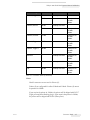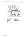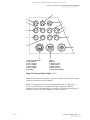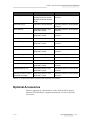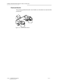
1
Videojet 1610
Dual Head
Operator Manual
Addendum
P/N 462219-01
Revision: AA, February 2011
Copyright February 2011, Videojet Technologies Inc.(herein referred to as Videojet). All rights reserved.
This document is the property of Videojet Technologies Inc. and contains confidential and proprietary
information owned by Videojet. Any unauthorized copying, use or disclosure of it without the prior
written permission of Videojet is strictly prohibited.
Videojet Technologies Inc.
1500 Mittel Boulevard
Wood Dale, IL
60191-1073 USA
www.videojet.com
Phone: 1-800-843-3610
Fax:
1-800-582-1343
Int’l Fax: 630-616-3629
Offices - USA: Atlanta, Chicago
Int’l: Canada, France, Germany, Ireland, Japan, Spain,
Singapore, The Netherlands, and The United Kingdom
Distributors Worldwide
Table of Contents
Chapter 1 — Introduction
Videojet 1610 Dual Head Printer . . . . . . . . . . . . . . . . . . . . . . . . . . . . . . 1–1
System Mode . . . . . . . . . . . . . . . . . . . . . . . . . . . . . . . . . . . . . . . . . . . 1–1
Independent Mode . . . . . . . . . . . . . . . . . . . . . . . . . . . . . . . . . . . . . . 1–1
About the Manual. . . . . . . . . . . . . . . . . . . . . . . . . . . . . . . . . . . . . . . . . . . 1–2
Related Publications. . . . . . . . . . . . . . . . . . . . . . . . . . . . . . . . . . . . . . . . . 1–2
Language Codes. . . . . . . . . . . . . . . . . . . . . . . . . . . . . . . . . . . . . . . . . 1–2
Content Presentation . . . . . . . . . . . . . . . . . . . . . . . . . . . . . . . . . . . . . . . . 1–4
The Word ‘Printer’ . . . . . . . . . . . . . . . . . . . . . . . . . . . . . . . . . . . . . . . 1–4
Safety Information . . . . . . . . . . . . . . . . . . . . . . . . . . . . . . . . . . . . . . . 1–4
Chapters in the Manual . . . . . . . . . . . . . . . . . . . . . . . . . . . . . . . . . . . . . . 1–5
Chapter 2 — Safety
Introduction. . . . . . . . . . . . . . . . . . . . . . . . . . . . . . . . . . . . . . . . . . . . . . . . 2–1
Chapter 3 — Main Parts
Videojet 1610 Dual Head Printer . . . . . . . . . . . . . . . . . . . . . . . . . . . . . . 3–2
Electronics Compartment . . . . . . . . . . . . . . . . . . . . . . . . . . . . . . . . . . . . 3–4
Printhead and Umbilical . . . . . . . . . . . . . . . . . . . . . . . . . . . . . . . . . . . . . 3–5
System Mode . . . . . . . . . . . . . . . . . . . . . . . . . . . . . . . . . . . . . . . . . . . 3–5
Independent Mode . . . . . . . . . . . . . . . . . . . . . . . . . . . . . . . . . . . . . . 3–5
Connector Panel . . . . . . . . . . . . . . . . . . . . . . . . . . . . . . . . . . . . . . . . . . . . 3–6
Pinout Information . . . . . . . . . . . . . . . . . . . . . . . . . . . . . . . . . . . . . 3–10
Chapter 4 — Printer Operation
Introduction. . . . . . . . . . . . . . . . . . . . . . . . . . . . . . . . . . . . . . . . . . . . . . . . 4–1
How to Clean Start and Clean Stop the Printer . . . . . . . . . . . . . . . . . . 4–2
How to Clean Start. . . . . . . . . . . . . . . . . . . . . . . . . . . . . . . . . . . . . . . 4–3
How to Clean Stop. . . . . . . . . . . . . . . . . . . . . . . . . . . . . . . . . . . . . . . 4–3
How to Quick Start and Quick Stop the Printer . . . . . . . . . . . . . . . . . 4–3
How to Quick Start . . . . . . . . . . . . . . . . . . . . . . . . . . . . . . . . . . . . . . 4–4
How to Quick Stop . . . . . . . . . . . . . . . . . . . . . . . . . . . . . . . . . . . . . . 4–4
System Menu. . . . . . . . . . . . . . . . . . . . . . . . . . . . . . . . . . . . . . . . . . . . . . . 4–4
Calibrate Menu . . . . . . . . . . . . . . . . . . . . . . . . . . . . . . . . . . . . . . . . . . . . . 4–5
Product Counter . . . . . . . . . . . . . . . . . . . . . . . . . . . . . . . . . . . . . . . . . . . . 4–6
Print Menu. . . . . . . . . . . . . . . . . . . . . . . . . . . . . . . . . . . . . . . . . . . . . . . . . 4–6
Head Mode . . . . . . . . . . . . . . . . . . . . . . . . . . . . . . . . . . . . . . . . . . . . . 4–6
Print Enable. . . . . . . . . . . . . . . . . . . . . . . . . . . . . . . . . . . . . . . . . . . . . 4–7
Print Control . . . . . . . . . . . . . . . . . . . . . . . . . . . . . . . . . . . . . . . . . . . . 4–7
Rev AA
1
Videojet 1610 Dual Head Operator Manual Addendum
Head Settings . . . . . . . . . . . . . . . . . . . . . . . . . . . . . . . . . . . . . . . . . . . 4–8
How to Print Messages . . . . . . . . . . . . . . . . . . . . . . . . . . . . . . . . . . . . . . 4–9
How to Start the Printing . . . . . . . . . . . . . . . . . . . . . . . . . . . . . . . . . 4–9
How to Stop the Printing. . . . . . . . . . . . . . . . . . . . . . . . . . . . . . . . . 4–10
Chapter 5 — User Interface
Introduction . . . . . . . . . . . . . . . . . . . . . . . . . . . . . . . . . . . . . . . . . . . . . . . . 5–1
Menu Description . . . . . . . . . . . . . . . . . . . . . . . . . . . . . . . . . . . . . . . . . . . 5–2
Messages . . . . . . . . . . . . . . . . . . . . . . . . . . . . . . . . . . . . . . . . . . . . . . . 5–2
Editor . . . . . . . . . . . . . . . . . . . . . . . . . . . . . . . . . . . . . . . . . . . . . . . . . . 5–3
Print . . . . . . . . . . . . . . . . . . . . . . . . . . . . . . . . . . . . . . . . . . . . . . . . . . . 5–4
System . . . . . . . . . . . . . . . . . . . . . . . . . . . . . . . . . . . . . . . . . . . . . . . . . 5–4
Configure . . . . . . . . . . . . . . . . . . . . . . . . . . . . . . . . . . . . . . . . . . . . . . . 5–5
Manage Messages . . . . . . . . . . . . . . . . . . . . . . . . . . . . . . . . . . . . . . . . . . . 5–6
To Select the Source for a Message . . . . . . . . . . . . . . . . . . . . . . . . . 5–6
Manage User Fields . . . . . . . . . . . . . . . . . . . . . . . . . . . . . . . . . . . . . . . . . 5–8
To Create a Custom User Field. . . . . . . . . . . . . . . . . . . . . . . . . . . . . 5–8
Manage Text. . . . . . . . . . . . . . . . . . . . . . . . . . . . . . . . . . . . . . . . . . . . . . . 5–10
To Modify Text Attributes . . . . . . . . . . . . . . . . . . . . . . . . . . . . . . . 5–11
Chapter 6 — Maintenance
Introduction . . . . . . . . . . . . . . . . . . . . . . . . . . . . . . . . . . . . . . . . . . . . . . . . 6–1
Chapter 7 — Troubleshooting
Introduction . . . . . . . . . . . . . . . . . . . . . . . . . . . . . . . . . . . . . . . . . . . . . . . . 7–1
Printhead Problem . . . . . . . . . . . . . . . . . . . . . . . . . . . . . . . . . . . . . . . 7–2
Appendix A — Specifications
Electrical Specifications . . . . . . . . . . . . . . . . . . . . . . . . . . . . . . . . . . . . .
Weight. . . . . . . . . . . . . . . . . . . . . . . . . . . . . . . . . . . . . . . . . . . . . . . . . . . .
Dimensions . . . . . . . . . . . . . . . . . . . . . . . . . . . . . . . . . . . . . . . . . . . . . . .
Environmental Specifications . . . . . . . . . . . . . . . . . . . . . . . . . . . . . . . .
Print Height . . . . . . . . . . . . . . . . . . . . . . . . . . . . . . . . . . . . . . . . . . . . . . .
Ink and Make-up Fluid Capacity . . . . . . . . . . . . . . . . . . . . . . . . . . . . .
Throw Distance . . . . . . . . . . . . . . . . . . . . . . . . . . . . . . . . . . . . . . . . . . . .
Communication Channels . . . . . . . . . . . . . . . . . . . . . . . . . . . . . . . . . . .
Status Outputs . . . . . . . . . . . . . . . . . . . . . . . . . . . . . . . . . . . . . . . . . . . . .
Print Control Inputs . . . . . . . . . . . . . . . . . . . . . . . . . . . . . . . . . . . . . . . .
Font Specifications and Line Speeds . . . . . . . . . . . . . . . . . . . . . . . . . .
S-Mode and I-Mode Functions and Differences. . . . . . . . . . . . . . . . .
2
A–1
A–1
A–2
A–4
A–4
A–5
A–5
A–5
A–5
A–6
A–7
A–8
Rev AA
Videojet 1610 Dual Head Operator Manual Addendum
Optional Accessories . . . . . . . . . . . . . . . . . . . . . . . . . . . . . . . . . . . . . . . A–9
Printhead Bracket. . . . . . . . . . . . . . . . . . . . . . . . . . . . . . . . . . . . . . A–10
Rev AA
3
1
Introduction
Videojet 1610 Dual Head Printer
The Videojet 1610 Dual Head (DH) printer is a continuous ink jet printer
that can print fixed and variable codes at elevated line speeds on
consumer and industrial products.
The most important feature of the printer lies in the Dual Head
configuration which differentiates this printer from the other 1000 line
series printers. It has the same architecture and features as the Videojet
1610 printers. The printer can print text, characters, logos and graphics (up
to 34 dots high) using one or both printheads in two different modes.
There are two printers available based on two different modes:
• Videojet 1610 Dual Head with System Mode
• Videojet 1610 Dual Head with Independent Mode
The printer with System mode (S-Mode) is the standard model. The printer
with Independent Mode (I-Mode) is an advanced model with the optional
I-Mode feature. Both the printers can operate in S-Mode. Only the printer
purchased with I-Mode set up, can run in independent mode.
System Mode
In System mode configuration, either one or both the printheads operate
on a single production line. It supports one product detector and one
encoder input to control both printheads. Both the printheads print on the
same product. Each printhead can print a separate message.
Independent Mode
In Independent mode, either one or both the printheads operate on up to
two different production lines. The printheads can operate independently.
Thus, I-Mode configuration allows up to two product detectors and two
encoder inputs to support independent printing on up to two lines. Each
printhead can print a separate message.
Rev AA
Videojet 1610 Dual Head Printer
1-1
Videojet 1610 Dual Head Operator Manual Addendum
Note: A printer with I-Mode can operate as a S-Mode printer but a S-Mode
printer cannot be operated as an I-Mode printer. In order to upgrade S-Mode
configuration to I-Mode configuration, the connector panel must be replaced. For
more information, please contact Videojet Technologies Inc. Customer Service
Department at 800.843.3610 (United States only), or contact the local Videojet
Technologies Inc. representative.
Note: Each printhead must be set up separately before printing.
About the Manual
This addendum is written for the operators of Videojet 1610 DH printer.
The document describes the significant differences between the Videojet
1610 DH printer and the Videojet 1610 printer. Therefore, this addendum
must be read in conjunction with Videojet 1610 Operator Manual (P/N
462128).
Related Publications
The following manuals is available for reference:
• Videojet 1610 Operator Manual, Part Number: 462128
• Videojet 1610 DH Service Manual Addendum, Part Number: 462220
• Videojet 1610 Service Manual, Part Number: 462129
Language Codes
When you order these manuals, make sure to add the 2-digit language
code at the end of the part number. For example, the spanish version of
the operator manual is part number 462219-04. Table 1-1 on page 1-3
shows the list of language codes that you can use to identify the translated
versions of this manual.
Note: The availability of the Operator Manual Addendum is indicated by an
asterisk (*). Availability of the Service Manual is indicated by a plus sign (+). For
more information, contact the Videojet distributor or subsidiary.
1-2
About the Manual
Rev AA
Videojet 1610 Dual Head Operator Manual Addendum
Code
Language
Availability (see
note)
01
English (US)
*
02
French
*
03
German
*
04
Spanish
*
05
Portuguese Brazilian
*
06
Japanese
*
07
Russian
*
08
Italian
*
09
Dutch
*
10
Chinese (Simplified)
*
11
Arabic
*
12
Korean
*
13
Thai
*
15
Norwegian
*
16
Finnish
*
17
Swedish
*
18
Danish
*
19
Greek
*
20
Hebrew
*
21
English (UK)
*
23
Polish
*
24
Turkish
*
25
Czech
*
26
Hungarian
*
33
Vietnamese
*
34
Bulgarian
*
36
Chinese (Traditional)
*
+
+
+
+
Table 1-1: Language Codes
Rev AA
Related Publications
1-3
Videojet 1610 Dual Head Operator Manual Addendum
Content Presentation
This addendum contains different types of information like safety
guidelines, additional notes, user interface (UI) terminology and so on.
Refer to Chapter 1, “Introduction” of the Videojet 1610 Operator Manual
(P/N 462128) for complete information on these topics.
The Word ‘Printer’
The word ‘printer’ indicates the ‘Videojet 1610 Dual Head printer’, from
this point onwards, in this manual.
In specific, Standard printers with S-Mode will be referred to as ‘Printer
(S)’ and printers with I-Mode will be referred to as ‘Printer (I)’.
Safety Information
The safety information includes warning and caution statements.
Warning
The warning statements indicate hazards or unsafe practices that can
cause severe personal injury or death. For example:
Warning
PERSONAL INJURY. The cleaning agent is poisonous if taken
internally. Do not drink. Seek medical attention immediately if
ingested.
Caution
The caution statements indicate hazards or unsafe practices that can cause
damage to the equipment. For example:
Caution
EQUIPMENT DAMAGE. Do not fit or remove any connector on the
printer when the power is turned on. The failure to follow this
caution can damage the printer.
1-4
Content Presentation
Rev AA
Videojet 1610 Dual Head Operator Manual Addendum
Chapters in the Manual
Chapter
No.
Chapter Name
Description
1.
Introduction
Contains the information about this manual, the related
publications, and writing styles used in this manual
2.
Safety
Contains the safety and hazard information
3.
Main Parts
Describes the main parts of the printer
4.
Printer Operation
Contains the information on how to set up and operate the
printer
5.
User Interface
Explains how to use the UI to create and save messages
6.
Maintenance
Contains the information on how to maintain and clean the
printer
7.
Troubleshooting
Contains the operator level diagnostic and troubleshooting
procedures
8.
Specifications
Contains printer specifications
Table 1-2: List of Chapters
Rev AA
Chapters in the Manual
1-5
2
Safety
Introduction
The policy of Videojet Technologies Inc. is to manufacture non-contact
printing/coding systems and ink supplies that meet high standards of
performance and reliability. We enforce strict quality control techniques to
eliminate potential defects and hazards in our products.
The intended use of the printer is to print information directly onto a
product. Use of this equipment in any other fashion may lead to serious
personal injury.
The safety guidelines provided in this chapter are intended to educate the
technicians on all safety issues so that the printer is serviced and operated
in a safe manner.
Refer to the Chapter 2, “Safety” of Videojet 1610 Operator Manual
(P/N 462128) for the following safety related information:
• General Safety Guidelines
• Electrical Safety Guidelines
• Fluid Safety Guidelines
• Compressed Air Safety Guidelines
• UI Related Safety Guidelines
• Other Important Guidelines
Caution
EQUIPMENT DAMAGE. Make sure the printer operates with
approved fluids only.
Rev AA
Introduction
2-1
Main Parts
3
This section describes the main parts of the printer. The connector panel
and printhead with umbilical are illustrated in detail for the 1610 DH
printer.
For other assemblies, refer to the Videojet 1610 Operator Manual (P/N
462128) for complete information:
• Control Panel Information
• Ink Compartment
• Main Power Switch
• Ink System Filter
Rev AA
3-1
Videojet 1610 Dual Head Operator Manual Addendum
Videojet 1610 Dual Head Printer
1
5
4
2
3
S-Mode
1. Control Panel
2. Ink Compartment
3. Umbilical
4. Printhead
5. Connector Panel*
6. Electronics Compartment**
7. Main Power Switch**
8. Ink System Filter**
*The connector panel is provided with three ports with plugs.
**The components are not shown in the picture.
Figure 3-1: Main Parts of the Printer
3-2
Videojet 1610 Dual Head Printer
Rev AA
Videojet 1610 Dual Head Operator Manual Addendum
1
5
4
2
3
I-Mode
1. Control Panel
2. Ink Compartment
3. Umbilical
4. Printhead
5. Connector Panel
6. Electronics Compartment*
7. Main Power Switch*
8. Ink System Filter*
*The components are not shown in the picture.
Figure 3-2: Main Parts of the Printer (I)
Rev AA
Videojet 1610 Dual Head Printer
3-3
Videojet 1610 Dual Head Operator Manual Addendum
Electronics Compartment
The electronics compartment contains the parts shown in Figure 3-3.
3
1
4
2
9
5
8
6
7
1. Double Headed Air Pump
2. Power Supply Unit
3. Extra High Tension (EHT) Block
4. Electronics Compartment Fan
5. Electronics Compartment
6. Main Power Switch
7. Printer Interface Board (PIB)
8. Control System Board
9. Connector Panel Boards
Figure 3-3: Electronics Compartment
Note: When a customer orders a Videojet 1610 DH printer with an air dryer, the
double headed air pump is removed from the printer. The air dryer supplies
positive air to the printhead from an external air source. Air dryers are required
when the printer is operated in an environment with elevated humidity or certain
water sensitive inks are used. Please contact Videojet Technologies Inc. Customer
Service Department at 800.843.3610 (United States only), or contact the local
Videojet Technologies Inc. representative for more information.
3-4
Electronics Compartment
Rev AA
Videojet 1610 Dual Head Operator Manual Addendum
Printhead and Umbilical
The printhead uses the ink supplied by the ink core module to print the
text and graphic characters on a product. The control signals and ink are
sent to the printhead through the umbilical.
2
1
1. Umbilical
2. Printhead
Figure 3-4: Printhead and Umbilical
In Dual Head configuration, both the printheads have the same design.
The printheads operates at an offset of up to two meters relative to each
other. The two printheads are independently controllable. Each printhead
must be set up separately.
The printheads can operate in two modes:
• System Mode
• Independent Mode
Refer to “Videojet 1610 Dual Head Printer” on page 1-1 for more
information on the different modes.
System Mode
Use one or two printheads to print on a single product line. Each
printhead is set up separately and can print a different message.
Independent Mode
Use one or two printheads to print on up to two product lines. Each
printhead is set up separately and can print a different message.
Rev AA
Printhead and Umbilical
3-5
Videojet 1610 Dual Head Operator Manual Addendum
Connector Panel
The connector panel is on the left side of the printer (item 5, Figure 3-1 on
page 3-2 and Figure 3-2 on page 3-3). The panel contains the connectors
shown in Figure 3-5 on page 3-8 for Printer (S) and Figure 3-6 on page 3-9
for Printer (I).
Note: The number of connectors provided depends on the model you select.
Note: To reconfigure your system from S-Mode to I-Mode, contact your Videojet
Technologies Inc. representative.
Table 3-1 provides the connectors for the printer.
Connector Type
PCB
Standard
COM 2
RS 232/485
PCB 7
Videojet 1610 DH
COM 1
RS 232/485
PCB 7
Relay Switches
PCB 7
PCB 6
Videojet 1610
DH with
I-Mode
Videojet 1610 DH
PCB 6
Videojet 1610
DH with
I-Mode
Videojet 1610 DH
PCB 6
Head 1, Beacon
PCB 7
Videojet 1610
DH with
I-Mode
Videojet 1610 DH
PCB 6
Head 1, Encoder
PCB 7
Videojet 1610
DH with
I-Mode
Videojet 1610 DH
PCB 6
Head 1, Trigger 2
PCB 7
PCB 6
Optional
Videojet 1610
DH with
I-Mode
Videojet 1610 DH
Videojet 1610
DH with
I-Mode
Table 3-1: Connector Panel
3-6
Connector Panel
Rev AA
Videojet 1610 Dual Head Operator Manual Addendum
Connector Type
PCB
Standard
Optional
Head 1, Trigger 1
PCB 7
Videojet 1610 DH
PCB 6
Head 2, Beacon
PCB 7
Videojet 1610
DH with
I-Mode
Videojet 1610 DH
PCB 6
Videojet 1610
DH with
I-Mode
Head 2, Encoder
PCB 6
Videojet 1610
DH with
I-Mode
Head 2, Trigger 2
PCB 6
Videojet 1610
DH with
I-Mode
Head 2, Trigger 1
PCB 6
Videojet 1610
DH with
I-Mode
Ethernet
-
Videojet 1610 DH
Videojet 1610
DH with
I-Mode
USB
-
Videojet 1610 DH
Videojet 1610
DH with
I-Mode
I/O
PCB 4
Videojet 1610 DH
Videojet 1610
DH with
I-Mode
Table 3-1: Connector Panel (Continued)
Notes:
Head 2 connectors are not used in Printer (S).
Printer (I) are configurable in either S-Mode and I-Mode. Printer (S) cannot
be operated in I-Mode.
If you require the printer in S-Mode, the printer will be shipped with PCB 7
(eight ports and three blanking plugs). If you require the printer in I-Mode,
the printer will be shipped with PCB 6 (eleven ports).
Rev AA
Connector Panel
3-7
Videojet 1610 Dual Head Operator Manual Addendum
1
12
2
11
3
4
10
5
9
Cat 5e
8
7
1. COM 1, RS 232/ RS 485
2. Relay Switches
3. Head 1, Trigger 2*
4. Head 1, Trigger 1*
5. Blanking Plugs
6. I/O 25 Way
7.USB
6
8. Ethernet
9. Head 2, Beacon
10. Head 1, Beacon
11. Head 1, Encoder
12.COM 2, RS 232/ RS 485
* - The connectors are used for both Head 1 and Head 2 Trigger, though it is labeled as Head 1,
Trigger 1 and Head 1, Trigger 2.
Figure 3-5: Connector Panel (S-Mode) - PCB 7
3-8
Connector Panel
Rev AA
Videojet 1610 Dual Head Operator Manual Addendum
1
14
2
13
3
4
5
12
6
11
10
Cat 5e
7
9
1. COM 1, RS 232/ RS 485
2. Relay Switches
3. Head 1, Trigger 2
4. Head 1, Trigger 1
5. Head 2, Trigger 2
6. Head 2, Trigger 1
7. I/O 25 Way
8
8.USB
9. Ethernet
10. Head 2, Encoder
11. Head 2, Beacon
12. Head 1, Beacon
13. Head 1, Encoder
14.COM 2, RS 232/ RS 485
Figure 3-6: Connector Panel (I-Mode) - PCB 6
Note: All the connectors are sealed to provide the required protection from water
and dust according to the IP65 standard.
Note: Two Communications ports are available which can be configured to
RS-232 or RS-485 by a user selectable link. When configured to RS-232,
hardware flow control (handshaking) is available for both Communication port 1
and port 2. Refer to the Service Manual for more information.
Rev AA
Connector Panel
3-9
Videojet 1610 Dual Head Operator Manual Addendum
Pinout Information
Part Number
Connector
Pinout
500-0036-584
COM 2
RS 232/485
DIN 8 Pin
COM 1
RS 232/485
DIN 8 Pin
500-0036-583
Relay Switches
DIN 7 Pin
500-0036-577
Head 1, Beacon
DIN 6 Pin
Head 2, Beacon
DIN 6 Pin
Head 1, Encoder
DIN 4 Pin
Head 2, Encoder (I-Mode only)
DIN 4 Pin
Head 1, Trigger 2
DIN 3 Pin
Head 1, Trigger 1
DIN 3 Pin
Head 2, Trigger 2 (I-Mode only)
DIN 3 Pin
Head 2, Trigger 1 (I-Mode only)
DIN 3 Pin
399083
Ethernet
-
399084
USB
-
399475
I/O
DIN 25 Pin (Bulgin)
500-0076-141
Din Dust Cap Plug
-
500-0036-581
500-0036-578
Table 3-2: Pinout Information
3-10
Connector Panel
Rev AA
4
Printer Operation
Introduction
This document provides the procedures to do the following tasks:
• Clean start and clean stop the printer
• Quick start and quick stop the printer
• System Menu
• Calibrate Menu
• Printer Configuration
• Print the Messages
For more information on the topics listed below, please refer to the
Videojet 1610 Operator Manual (P/N 462128):
• Turn on the printer
• How to Set the Passwords
• How to Configure Ethernet Port
• How to Enter Service Information
• Data Logging Menu
• How to Configure the Serial Port
• High Speed Remote Data Transfer
• How to Create a Message
• Manual Print
• Continuous Print
• DIN Print
• Turn off the printer
Caution
Make sure that the right head is selected for the task you are
performing.
Rev AA
Introduction
4-1
Videojet 1610 Dual Head Operator Manual Addendum
Important Notes
Note 1: The user must be at password level 2 to access these options.
Note 2: The operating head is displayed on the bottom right corner of the screen.
For example,
Operating Head
Note 3: The alarm/warning messages are prefixed with (1) or (2) indicating the
printheads.
For example,
Printheads
Note 4: Press F3 to toggle between the two heads when on a menu.
How to Clean Start and Clean Stop the Printer
The default procedures to start and stop the printer are the Clean Start and
the Clean Stop.
Note: If the Clean Start or the Clean Stop are not available, the printer requests a
Quick Start or Quick Stop. The printer cannot provide the Clean Start and the
Clean Stop options if the make-up cartridge is empty
or if the ink core high
warning is present. Make sure that the make-up cartridge is not empty.
Caution
PERFORMANCE. Avoid excessive use of Clean Start or Clean Stop.
The failure to follow this caution can cause high use of flush and
dilution of the ink. The diluted ink decreases the quality of the print.
4-2
How to Clean Start and Clean Stop the Printer
Rev AA
Videojet 1610 Dual Head Operator Manual Addendum
How to Clean Start
To clean start, do the following tasks:
1 Press F1 key for the Select Head dialog box to appear.
Figure 4-1: Select Head
2 Select the required head from the options available using the Left and
Right arrow keys. The options are:
• Head 1
• Head 2
• Both Heads
3 Press Enter, the printer turns on the ink and the selected head ink jet
starts.
Note: To stop the ink jet, press the F1 key.
How to Clean Stop
Press the F1 key. The printer stops the flow of ink.
Note: This command is head specific and starts one head only. To start the second
head when one head is running, press ‘F3’ to select the required head, then select
‘F1’ to Clean Start.
How to Quick Start and Quick Stop the Printer
Press CTRL+F1 key to Quick Start the jet. Alternatively, you can Quick
Start and Quick Stop the jet by System > Quick Start Jet and System > Quick
Stop Jet.
Rev AA
How to Quick Start and Quick Stop the Printer
4-3
Videojet 1610 Dual Head Operator Manual Addendum
How to Quick Start
To quick start, do the following tasks:
1 Press CTRL+F1 key for the Select Head dialog box to appear.
Figure 4-2: Select Head
2 Select the required head from the options available using the Left and
Right arrow keys. The options are:
• Head 1
• Head 2
• Both Heads
3 Press Enter, the printer turns on the ink and the selected head ink jet
starts.
Note: To stop the ink jet, press the CTRL+F1 key.
How to Quick Stop
Press the CTRL+F1 key. The printer stops the flow of ink.
Note: This command is head specific and starts one head only. To start the second
head when one head is running, press ‘F3’ to select the required head, then select
‘CTRL+F1’ to Quick Start.
System Menu
The user can perform the start and stop sequences through System menu
with the options available as Head 1, Head 2 and Both Heads. The user can
also see the Current Alarms, Current Warnings and Current States of the
printer through System menu. The alarm/warning messages are prefixed
with (1) or (2) indicating the operating printhead.
For example,
.
For more information on alarms and warnings, refer Chapter 4 of Videojet
1610 Operator Manual (P/N 462128).
4-4
System Menu
Rev AA
Videojet 1610 Dual Head Operator Manual Addendum
Note: System Menu is different from System Mode (S-Mode). System Mode can
be set in Print Menu (refer “Print” on page 5-4).
Calibrate Menu
The Calibrate menu includes the controls to setup and calibrate the printer.
Refer to the Videojet 1610 Service Manual for more information.
The Diagnostics screens are available for both the printheads depending on
the printhead selected.
Note: Press F3 to toggle between the two heads when on a menu.
Table 4-1 lists the menu options which are unique to 1610 Dual Head
configuration.
Calibrate Menu
Commands
Function
Input Line
Configuration
Opens the Input Line Setup dialog box. You
can configure up to five digital inputs.
Inputs:
• Increment a counter
• Reset a counter
• Stop a jet
Output Line
Configuration
Opens the Output Line Setup dialog box. You
can configure up to six digital outputs.
Outputs:
• When printhead is enabled
• Warnings or alarms
• Print complete signal
Table 4-1: Calibrate Menu and Commands
Rev AA
Calibrate Menu
4-5
Videojet 1610 Dual Head Operator Manual Addendum
Product Counter
Figure 4-3: Product Counter Dialog Box
You can reset the product counter for Head 1 and Head 2. For more
information on how to reset and hide product counter, refer Chapter 4 of
Videojet 1610 Operator Manual (P/N 462128).
Print Menu
Note: Press F1 key to select the required printhead.
The printer is configured through the Print menu (see Figure 4-4). Press
Alt+P to open the Print menu.
Figure 4-4: Print Menu
Head Mode
In Printer (S), the Head Mode will be set up for System mode only. In Printer
(I), you can change the Head Mode between System and Independent.
Do the following tasks to select the type of head mode:
1 Select Head Mode from the Print menu.
2 Press the Enter key to open the Head Mode dialog box.
4-6
Product Counter
Rev AA
Videojet 1610 Dual Head Operator Manual Addendum
Figure 4-5: Head Mode
3 Select the Head Mode from the options available. The options are:
• System - In System mode configuration, either one or both the printheads
operate on a single production line. Each printhead can print a separate
message.
• Independent - In Independent mode, either one or both the printheads operate
on up to two different production lines. Each printhead can print a separate
message.
4 Press the Enter key to set the Head Mode and exit the Head Mode dialog
box.
Print Enable
Select the Print Enable option from the Print menu. The Print Enable dialog
box (see Figure 4-6) appears. You can Enable or Disable Head 1 and Head 2.
Figure 4-6: Print Enable
Note: In S-Mode, one printhead cannot be enabled if the other printhead is
already enabled. Both the printheads must be disabled first to enable the other
printhead.
Print Control
Select the Print Control option from the Print menu. The Print Control
menu appears.
Press F3 key to toggle between the two heads.
Note: Refer to Videojet 1610 Operator Manual (P/N 462128) for more
information on Print Control menu.
Rev AA
Print Menu
4-7
Videojet 1610 Dual Head Operator Manual Addendum
Figure 4-7: Print Control
Photocell Source
The print is activated from the source External (standard-connection
option), or None.
Note: Head 1 and Head 2 specific DIN Connections are available.
Remote Source Action
Provides instructions to the printer when the record buffer runs out of
data:
• Stop - The printer will stop the print when it reaches the end of the
buffer.
• Repeat Last Value – The printer will continue to print the last message
when it reaches the end of the buffer.
Head Settings
Select the Head Settings option from the Print menu (see Table 4-1 on
page 4-9).
Figure 4-8: Head Settings
4-8
Print Menu
Rev AA
Videojet 1610 Dual Head Operator Manual Addendum
Parameter
Description
Head Offset
Distance between print trigger and
printhead in inches.
Throw distance
Distance between the printhead and the
product in inches.
Character Height
Height of overall message.
Reverse/Invert
Reversed/Inverted character printing.
Table 4-1: Head Settings
Note 1: Head Offset is the distance between the print trigger and the printhead
(in inches). Measure the head offset for both the printheads and input for each
head correctly.
Note 2: Product delay (message parameter) is the distance between the edge of the
product and the print start position (in inches). The total delay between printhead
trigger and print = product delay + head offset.
How to Print Messages
You must select a message before you start the printing process. For
information on how to select a message, refer Videojet 1610 Operator
Manual (P/N 462128).
Caution
MESSAGE. Make sure that the right head is selected before you
select a message for printing. Press F3 key to select the required
printhead.
How to Start the Printing
The default sequence is Clean Start.
Enable the print to start the printing (access Print > Print Enable). Select
Enable for the required head.
The jet running icon is prefixed with the operating head number. For
example,
Rev AA
.
How to Print Messages
4-9
Videojet 1610 Dual Head Operator Manual Addendum
For information on how to start the printing, refer 1610 Videojet 1610
Operator Manual (P/N 462128).
Note: To select the specific printhead parameters and photocells, you must select
the correct printhead. Press F3 key to select the required printhead. The selected
printhead is highlighted on the bottom right hand side of the UI as well as at the
bottom of the pop up window.
How to Stop the Printing
Disable the print to stop the printing (access Print > Print Enable). Select
Disable for the required head.
The jet stop icon is prefixed with the head number indicating the stopped
jet. For example,
.
For information on how to stop the printing, refer 1610 Videojet 1610
Operator Manual (P/N 462128).
4-10
How to Print Messages
Rev AA
5
User Interface
Introduction
The User Interface contains the Menu screen.
Refer to Chapter 5, “User Interface” of Videojet 1610 Operator Manual
(P/N 462128) for complete information on the following topics:
• Menu Description
• To Select the Menus and Items
• To Enter the Text, Numbers and Toggle Values
• Manage Messages
• Manage User Fields
• Manage Text
• Manage Logos
Note: The user must be at password level 2 to access these options.
Menu Screen
Figure 5-1: Main Screens
Rev AA
Introduction
5-1
Videojet 1610 Dual Head Operator Manual Addendum
Menu Screen
When you login, the first screen that appears is the Menu screen. The
Menu screen has a row of menus along the top of the screen. The menus
give quick and easy access to the different functions of the printer. You
can see only five menus in the screen (see Figure 5-1), use the Left arrow
key or Right arrow key to access the other menus.
Menu Description
This section describes few commands in Messages, System and Configure
Menus. Refer to the Videojet 1610 Operator Manual (P/N 462128) for the
complete information on the other commands on Messages, Editor, User
Fields, Print, Password, System, and Configure menus.
Messages
Messages Menu
Commands
Function
Message Select
Source
Opens the Message Select Source dialog box,
with options Internal, Barcode Scan and WSI
Protocol.
Use the options to configure how the inputs
are read (optional for 1610 DH).
Table 5-1: Messages Menu and Commands
5-2
Menu Description
Rev AA
Videojet 1610 Dual Head Operator Manual Addendum
Messages Menu
Commands
Function
Edit Barcode Scan
Select Table
Opens the Barcode Scan Message Select
Table dialog box.
Table 5-1: Messages Menu and Commands (Continued)
Editor
The commands in the Editor menu are shown only if the Message Editor is
open. If the Message Editor is closed, the only option shown in the Editor
menu is "Only used when in Editor".
Note: The command In-line Attributes is not available in Videojet 1610 DH UI.
Note: All Editor commands are available for level 1 and above users.
Note: For more information on Editor menu refer Videojet 1610 Operator
Manual (P/N 462128).
Rev AA
Menu Description
5-3
Videojet 1610 Dual Head Operator Manual Addendum
Print
Print Menu
Commands
Function
Print Enable
Opens the Print Enable dialog box. You can Enable or
Disable Head 1 and Head 2.
Print Control
Opens the Print Control dialog box.
Head Mode
Opens the Head Mode dialog box.
You can toggle the Head Mode between System and
Independent mode.
Head Settings
Opens the Head Settings dialog box.
Note: Head Offset is the distance between the print
trigger and printhead in inches.
Table 5-2: Print Menu and Commands
System
For Clean Start Jet, Quick Start Jet, Clean Stop Jet and Quick Stop Jet
commands, select Head 1, Head 2 or Both Heads.
Note: Select the correct option for Head 1, Head 2 or Both Heads using the left
and right arrow keys.
5-4
Menu Description
Rev AA
Videojet 1610 Dual Head Operator Manual Addendum
For Nozzle Flush, System Flush Purge, Umbilical Purge commands, select
either Head 1 or Head 2.
Configure
Configure Menu
Commands
Function
Serial Port
Configuration
You can configure the Serial1 and Serial2 ports.
Special Printing
Mode
Selects DIN printing and traversing printing.
Protocol
Configuration
Opens the Protocol Configuration dialog box.
Table 5-3: Configure Menu and Commands
Rev AA
Menu Description
5-5
Videojet 1610 Dual Head Operator Manual Addendum
Configure Menu
Commands
Function
Barcode Scan
Setup
Opens the Barcode Scan Setup dialog box.
Table 5-3: Configure Menu and Commands (Continued)
Manage Messages
Refer to Chapter 5, “User Interface” of Videojet 1610 Operator Manual
(P/N 462128) for complete information on the following topics:
• To Create a Message
• To Edit a Message
• To Select the Source for a Message
• To Copy and Paste a Message
• To Enter Multiple Lines in a Message
• To Set the Message and Default Parameters
• To Clear a Message
• To Save a Message
• To Save a Message and Exit
• To Exit without Saving the Message
• To Delete a Message
To Select the Source for a Message
You can set and select the stored messages in the machine by the following
options:
• Internal
• Barcode Scan
5-6
Manage Messages
Rev AA
Videojet 1610 Dual Head Operator Manual Addendum
• WSI Protocol
1 Press the Alt+M keys. The Messages menu appears.
2 Select Message Select Source. The Message Select Source Menu appears.
Figure 5-2: Message Select Source - Internal Source
3 Use the arrow keys to select the required source - Internal, Barcode Scan
or WSI Protocol. Refer to the WSI Communications Protocol (P/N
462115) for more information on WSI protocols.
4 Select the Barcode Scan option.
5 Select the data source - Barcode scan queue or Last received barcode scan
for barcode scan source.
Figure 5-3: Message Select Source - Barcode Scan
6 Press the Enter key to set the source and return to the Message Editor
screen.
7 Select the Messages menu again. Select the Edit Barcode Scan Select
Table.
Figure 5-4: Edit Barcode Scan Select Table
8 Enter the names into the table locations for the parallel bit values from
the barcode scan code table.
9 Press the F2 key to select the message names from a list of those
available.
Rev AA
Manage Messages
5-7
Videojet 1610 Dual Head Operator Manual Addendum
10 When you assign all the messages that must be available for the
barcode scan, press the Enter key to return to the Message Editor
screen. Else, press the Esc key to return to the Message Editor screen
without any changes.
Manage User Fields
There are many pre-defined user fields in the software.
• Hour of the week - Number of hours from the start of the configured
rollover day for the week. Use this option to print the current hour
from the configured start of the week. The range is between 0 and 168.
For information on other pre-defined user fields, refer Videojet 1610 Operator
Manual (P/N 462128).
Refer to Chapter 5, “User Interface” of Videojet 1610 Operator Manual
(P/N 462128) for complete information on the following topics:
• To Insert a User Field
• To Insert a Pre-defined User Field
• To Edit a User Field
• To Delete a User Field
• To Create a Custom User Field
• To Reset a Message Counter
• To Set Shifts
• To Set the Timer
• To Set the Encoded Hour
• To Set the Encoded Day of the Week
To Create a Custom User Field
To Set Text Attributes
List Prompt
User can select their contents from a list when the message is selected to
print. When the field is created, the user can define the prompt message
and the list of values that will be available on the input.
5-8
Manage User Fields
Rev AA
Videojet 1610 Dual Head Operator Manual Addendum
To Define a List Prompt
When a message that contains a list prompt is loaded, the operator is
asked to provide the contents for the field.
Do the following tasks to add list prompt attribute to the User fields:
1 Press the Alt+U keys. The User Fields menu appears.
Figure 5-5: User Fields Menu
2 Select New User Field and press the Enter key. The New User Field
dialog box appears.
Figure 5-6: New User Field Dialog Box
3 Enter a name for the User Field.
4 Highlight the Description option using the Down arrow key.
5 Select the Text option using the Left and Right arrow keys.
6 Press the Enter key to open the configuration dialog box for text user
fields (see Figure 5-7).
Figure 5-7: Attribute - List Prompt
7 Enter a default value for the list prompt, which is related to the field
with the label Text. This text is displayed in the list prompt until the
operator deletes the text and enters new information.
8 Highlight Attribute option using the Down arrow key.
9 Select the List Prompt option using the Left and Right arrow keys.
Rev AA
Manage User Fields
5-9
Videojet 1610 Dual Head Operator Manual Addendum
10 Press the Enter key to open the configuration dialog box for list
prompt (see Figure 5-8).
Figure 5-8: Configure List Prompt
11 Enter the value for Number of options field.
12 Highlight Default option type option using the Down arrow key.
13 Use the Left arrow key and Right arrow key to select one of the
following types of default options:
• Specified line
• Blank line
• Last line used
14 Press the Enter key to open the Option list dialog box.
Figure 5-9: Option List Dialog
15 Enter the list of options and press Enter to save the created list prompt
and exit the option list dialog box.
Refer to “To Modify Text Attributes” in Chapter 5, “User Interface” of
Videojet 1610 Operator Manual (P/N 462128) for more information.
Manage Text
Refer to Chapter 5, “User Interface” of Videojet 1610 Operator Manual
(P/N 462128) for complete information on the following topics:
• To Change Font Case
• To Set Font Height
• To Select Content
• To Copy and Paste Text
• To Modify Text Attributes
5-10
Manage Text
Rev AA
Videojet 1610 Dual Head Operator Manual Addendum
• To Insert Foreign Language Characters
To Modify Text Attributes
The Modify Attributes option allows the operator to change the attributes
of the selected content displayed in the editor screen.
Refer to Chapter 5, “User Interface” of Videojet 1610 Operator Manual (P/
N 462128) for more information on this topic.
Figure 5-10: Editor Attributes
Rev AA
Manage Text
5-11
6
Maintenance
Introduction
The maintenance of the printer includes the procedures that an
operator can perform. This chapter describes the maintenance tasks
that the operators of the printer are allowed to perform. The other
maintenance tasks that only the trained service technicians and
personnel must perform are described in the Service Manual.
Warning
PERSONAL INJURY. It is possible that in a fault condition the heater
can reach 70° C. Do not touch the plate on which heater is installed.
The failure to follow this warning can cause the personal injury.
Refer to the Chapter 6, “Maintenance” of the Videojet 1610 Operator
Manual (P/N 462128) for complete information on following
maintenance procedures.
• Maintenance Schedule
• Replace Smart Cartridges
• Inspect the Printhead
• Clean the Printhead
• Clean the Printer Cabinet
Rev AA
Introduction
6-1
7
Troubleshooting
Introduction
This chapter contains the troubleshooting and fault diagnosis information
for the everyday users of the printer. The service manual has more
information on troubleshooting for the service technician and trained
personnel.
Warning
LETHAL VOLTAGES. Lethal voltages are present within this
equipment when the equipment is connected to the main electrical
supply. Only trained and authorized personnel must do the
maintenance work. Observe all statutory electrical safety codes and
practices. Unless it is necessary to run the printer, disconnect the
printer from the main electrical supply before you remove the covers
or do any service or repair activity. The failure to follow this
warning can cause death or personal injury.
Warning
PERSONAL INJURY. It is possible that in a fault condition the heater
can reach 70° C. Do not touch the plate on which heater is installed.
The failure to follow this warning can cause the personal injury.
Refer to Chapter 7, ‘Troubleshooting’ of the Videojet 1610 Operator
Manual (P/N 462128) for complete information on following
troubleshooting procedures.
• The Printer Does Not Start
Note: If the printer does not start with Clean Start, perform a Quick Start.
• Incorrect Print Position
• Incorrect Print Size
• Print Not Complete
Rev AA
Introduction
7-1
Videojet 1610 Dual Head Operator Manual Addendum
• Poor Print Quality
• Printer Status Icons
Note: Head specific warnings will be prefixed with the head number.
For example
: indicates that the temperature of Printhead 1 is too low.
Note: Incase, a fault occurs in one of the printheads, then this fault can be reset
while the other printhead is still in operation.
Printhead Problem
Problem
Action
Printhead does not respond as
expected
Make sure correct printhead is
selected.
Table 7-1: Problem and Action
7-2
Introduction
Rev AA
A
Specifications
Electrical Specifications
The electrical specifications of the printer are shown in Table A-1.
Voltage
100 V AC to 240 V AC
Frequency
50 Hz to 60 Hz
Power Consumption
120 watts Maximum
Table A-1: Electrical Specifications
Weight
The dry weight specification of the printer is shown in Table A-2.
Dry Weight
22 kg
Table A-2: Weight Specifications
Rev AA
Electrical Specifications
A-1
Videojet 1610 Dual Head Operator Manual Addendum
Dimensions
480.1 mm
(18.9 inches)
379 mm
361 mm
(14.21 inches)
19 mm
(0.75 inches)
(14.92 inches)
338 mm
(13.30 inches)
345 mm
(13.58 inches)
180 mm
(7.08 inches)
32.50 mm
(1.28 inches)
305 mm
(12.00 inches)
25 mm
(0.98 inches)
(21.77 inches)
553 mm
280 mm
(11.02 inches)
20 mm
(0.79 inches)
Figure A-1. Printer Dimensions
A-2
Dimensions
Rev AA
Videojet 1610 Dual Head Operator Manual Addendum
39°
218 mm
(8.6 inches)
389 mm
(15.31 inches)
566 mm
(22.28 inches)
Both Doors Open
Ø 21.2 mm
(0.83 inches)
269.8 mm
(10.62 inches)
249.1 mm
(9.80 inches)
Ø 41.3 mm
(1.62 inches)
209.1 mm
(8.23 inches)
Printhead
Figure A-2. Printer Dimension (continued)
Cabinet
Width
345 mm
Height
533 mm
Depth
338 mm
Table A-3: Printer Dimensions
Rev AA
Dimensions
A-3
Videojet 1610 Dual Head Operator Manual Addendum
Printhead
Umbilical Length*
Cabinet Variation
Diameter
41.3 mm
Diameter of the
Nozzle Orifice
70 and 60 Microns
Standard
3 Meter
Option
6 Meter
Standard
IP 65
Table A-3: Printer Dimensions
Note: Both the printheads must use the same umbilical length (3 m or 6 m).
Note: The two printheads may operate with head elevations at a maximum of two
meters offset between heads.
Environmental Specifications
The environmental specifications of the printer are shown in Table A-4.
Operating temperature
5 ºC to 45 ºC (41 ºF to 113 ºF)
Rate of change of ambient
temperature
10 ºC (18 º F) per hour maximum
Relative humidity
0% to 90 % non-condensing
Storage temperature
5 ºC to 50 ºC (41ºF to 122 ºF) in original
packaging
Industrial-protection rating
IP65 is standard
Table A-4: Environmental Specifications
Print Height
The minimum and maximum height of the message for the print matrix is
shown in Table A-5.
2 mm
Minimum
12 mm
Maximum
Table A-5: Print Height
A-4
Environmental Specifications
Rev AA
Videojet 1610 Dual Head Operator Manual Addendum
Ink and Make-up Fluid Capacity
Ink Cartridge
750 millimeters
Make-up Fluid
Cartridge
750 millimeters
Table A-6: Ink and Make-up Fluid Capacity
Throw Distance
The optimum throw distance is 12 mm (range of 5 mm to 15 mm).
Communication Channels
Port
Specification
Connector
Ethernet
10/100 MBPS (with Interdependently addressed printheads)
RJ 45
USB (1)
1.1 (12 MBPS) Host Mode only
Type A Socket
(External)
USB (2)
1.1 (12 MBPS) Host and Device mode
Type A Socket
(Internal)
Comms 1 RS232/
485
75-230K Baud with Hardware Flow Control (RS232
only).
8 Pin Din
Connector
Comms 2 RS232/
485
75-230K Baud with Hardware Flow Control (RS232
Only)
8 Pin Din
Connector
Table A-7: Communication Channels
Status Outputs
Port
Specification
Connector
2 X Beacon
24V, 1A supply plus four pull down channels
(Red, Amber, Green and Klaxon)
6 way Din
Table A-8: Status Outputs
Rev AA
Ink and Make-up Fluid Capacity
A-5
Videojet 1610 Dual Head Operator Manual Addendum
Port
Specification
Connector
Dual Select
Relays
24V, 1A rated Volt free Relay 1 = follows green
24V, 1A rated Volt free Relay 2 = follows amber
7 way Din
Table A-8: Status Outputs (Continued)
Print Control Inputs
System Mode
Port
Specification
Photocell x 2
15 V, 1A fused supply
100 Hz, NPN/PNP Opto Isolated Input
Shaft encoder x 1
15 V, 1A fused supply
2 x 100 KHz direct inputs (supporting single
phase or quadrature encoders)
Barcode scanner message
select
Uses RS232 or USB input
Table A-9: System Mode
Independent Mode
Port
Specification
Photocell x 4
15 V, 1A fused supply
100 Hz, NPN/PNP Opto Isolated Input
Shaft encoder x 2
15 V, 1A fused supply
2 x 100 KHz direct inputs (supporting single
phase or quadrature encoders)
Barcode scanner message
select
Uses RS232 or USB input
Table A-10: Independent Mode
Note: Photocells 1 and 2 are specific for printhead 1 and S-Mode. Photocell 3 and
4 are for printhead 2 only.
Note: There will be an encoder input for each printhead for independent
encoding.
A-6
Print Control Inputs
Rev AA
Videojet 1610 Dual Head Operator Manual Addendum
Font Specifications and Line Speeds
The fonts available for the printer are listed in Table A-11.
Line
Mode
Height
Width
Cal. Mid Speeds
ft/min
m/min
1
5
5
914
278.6
1
7
4
960
292.6
1
7
5
800
243.8
1
9
7
533*
162.5
1
12
9
256
78.03
1
16
10
194
59.13
1
24
16
95
28.96
1
34
25
55
16.15
2
5
5
376*
114.6
2
7
4
480*
146.30
2
7
5
400*
121.92
2
9
7
229*
69.79
2
12
9
85
25.91
2
16
10
55
16.76
3
5
5
118
35.97
3
7
4
265*
80.77
3
7
5
221*
67.36
3
9
7
121*
36.88
4
5
5
85
25.91
4
7
4
67
20.42
4
7
5
55
16.76
5
5
5
55
16.76
Table A-11: Fonts
*high speed non-linear rasters
Note: The line speeds indicate the speed per printhead.
Rev AA
Font Specifications and Line Speeds
A-7
Videojet 1610 Dual Head Operator Manual Addendum
S-Mode and I-Mode Functions and Differences
Function
S-Mode
I-Mode
EHT On/Off
Separate printhead 1 and
printhead 2 control
Separate printhead 1 and printhead
2 control
EHT Setting
Separate printhead 1 and
printhead 2 control
Separate printhead 1 and printhead
2 control
Product Counter
Separate printhead 1 and
printhead 2 control
Separate printhead 1 and printhead
2 control
Run Hours
Common to both printheads
Common to both printheads
Print Trigger 1 - Head 1
Controls both printheads
Controls printhead 1
Print Trigger 2 - Head 1
Controls both printheads
traverse
Controls printhead 1 traverse
Print Trigger 1 - Head 2
Not used
Controls printhead 2
Print Trigger 2 - Head 2
Not used
Controls printhead 2 Traverse
Modulation
Separate printhead 1 and
printhead 2 control
Separate printhead 1 and printhead
2 control
Viscosity Calibration
Separate printhead 1 and
printhead 2 control
Separate printhead 1 and printhead
2 control
Gutter Pump Speed
Common to both printheads
Common to both printheads
Printhead Elevation
Separate printhead 1 and
printhead 2 control - Limit to
2m between heads
Separate printhead1 and printhead
2 control - Limit to 2m between
heads
Smart Chip Data
Common to both printheads
Common to both printheads
Clear Alarms and Warnings
Common to both printheads
Common to both printheads
Head 1 Encoder
Controls both printheads - if
external shaft encoder
selected
Controls printhead 1 - if external
shaft encoder selected
Head 2 Encoder
Not Used
Controls printhead 2 - if external
shaft encoder selected
Nozzle Flush
Separate printhead 1 and
printhead 2 control
Separate printhead 1 and printhead
2 control
Print Enable
Separate printhead 1 and
printhead 2 control
Separate printhead 1 and printhead
2 control
Password Control
Common to both printheads
Common to both printheads
Table A-12: S-Mode and I-Mode Functions and Differences
A-8
S-Mode and I-Mode Functions and Differences
Rev AA
Videojet 1610 Dual Head Operator Manual Addendum
Function
S-Mode
I-Mode
Line Configuration
Common to both printheads
(pulses/internal line speed/
product size/divider strokes/
units)
Separate printhead 1 and printhead
2 control
Continuous Print
Common to both printheads
Separate printhead 1 and printhead
2 control
Head Settings
Separate printhead 1 and
printhead 2 control
Separate printhead 1 and printhead
2 control
Messages
Separate printhead 1 and
printhead 2 control
Separate printhead 1 and printhead
2 control
User Fields
Common to both printheads
Common to both printheads
Umbilical Purge
Separate printhead 1 and
printhead 2 control
Separate printhead 1 and printhead
2 control
Ink Core Operations
Common to both heads
Common to both heads
Valve Test
Separate printhead 1 and
printhead 2 control
Separate printhead 1 and printhead
2 control
Network Settings
Common to both printheads
Common to both printheads
RS 232/485 Settings
Common to both printheads
Common to both printheads
Backup/Restore
Common to both printheads
Common to both printheads
System Flush Purge
Separate printhead 1 and
printhead 2 control
Separate printhead 1 and printhead
2 control
Starting/Stopping Jets
Separate printhead 1 and
printhead 2 control
Separate printhead 1 and printhead
2 control
Message selection method
(internally barcodes)
Separate printhead 1 and
printhead 2 control
Separate printhead 1 and printhead
2 control
Table A-12: S-Mode and I-Mode Functions and Differences (Continued)
Optional Accessories
Refer to Appendix A, ‘Specifications’ of the Videojet 1610 Operator
Manual (P/N 462128) for complete information on various optional
accessories.
Rev AA
Optional Accessories
A-9
Videojet 1610 Dual Head Operator Manual Addendum
Printhead Bracket
The existing printhead stand is used with a new bracket to mount both the
printheads.
Figure A-3. Dual Head Bracket
A-10
Optional Accessories
Rev AA