1
Videojet 1310
Operator Manual
P/N 361540-01
Revision: AC, October 2005
Copyright 2005, Videojet Technologies Inc. (herein referred to as Videojet). All rights reserved.
This document is the property of Videojet Technologies Inc. and contains confidential and
proprietary information owned by Videojet. Any unauthorized copying, use or disclosure of it
without the prior written permission of Videojet is strictly prohibited.
Videojet Technologies Inc.
1500 Mittel Boulevard
Wood Dale, IL
60191-1073 USA
www.videojet.com
Phone: 1-800-843-3610
Fax:
1-800-582-1343
Int’l Fax: 630-616-3629
Offices - USA: Atlanta, Chicago
Int’l: Canada, France, Germany, Ireland, Japan, Spain,
Singapore, The Netherlands, and The United Kingdom
Distributors Worldwide
Compliance Information
For Customers in the U.S.A.
This device complies with Part 15 of the FCC Rules. Operation is
subject to the following two conditions: 1) this device may not cause
harmful interference, and 2) this device must accept any interference
received, including interference that may cause undesired operation.
Caution
Changes or modifications to this unit not expressly approved by
the party responsible for compliance could void the user’s
authority to operate the equipment.
This equipment has been tested and found to comply with the limits
for a Class A digital device, pursuant to Part 15 of the FCC Rules.
These limits are designed to provide responsible protection against
harmful interference when the equipment is operated in a commercial
environment. This equipment generates, uses, and can radiate radio
frequency energy and, if not installed and used in accordance with the
instruction manual, may cause harmful interference to radio
communications. Operation of this equipment in a residential area is
likely to cause harmful interference. In such cases, the users will be
required to correct the interference at their own expense.
Shielded cables must be used with this unit to ensure compliance with
Class A FCC limits.
The user may find the following booklet prepared by the Federal
Communications Commission helpful: How to Identify and Resolve
Radio-TV Interference Problems. This booklet is available from the
U.S. Government Printing Office, Washington, DC 20402, Stock No.
004-00-00345-4. This equipment has been tested and certified for
compliance with U.S. regulations regarding safety and electrical
emissions by TUV Rheinland of North America, Inc.
For Customers in Canada
This digital apparatus does not exceed the Class A limits for radio
noise emissions from digital apparatus set out in the Radio
Interference Regulations of the Canadian Department of
Communications.
This equipment has been tested and certified for compliance with
Canadian regulations regarding safety and electrical emissions by
TUV Rheinland of North America, Inc.
Rev AC
i
Videojet 1310 Operator Manual
Pour la Clientèle du Canada
Le present appareil numerique n’emet pas de bruits radioelectriques
depassant les limites applicales aux appareils numerique de las class A
prescrites dans le Reglement sur le brouillage radioelectrique edicte
par le ministere des Communications du Canada.
Cet équipement est certifié CSA.
For Customers in the European Union
This equipment displays the CE mark to indicate conformance to the
following legislation.
• EN60950-1: 2001 Safety Requirements for Information Technology
Equipment
• EN61000-3-2: 1995 Limits for harmonic currents emissions
(equipment input current < 16A per phase)
• EN61000-3-3: 1995 Limitation of voltage fluctuation and flicker in
low-voltage supply systems for equipment with rated input
current < 16A.
• EN61000-4-2: 1995 ESD Requirements
• EN61000-4-3: 1997 Radiated Susceptibility
• EN61000-4-4: 1995 Electrical Fast Transient Burst Requirement
• EN61000-4-6: 1996 Immunity to conducted disturbances, induced
by radio-frequency fields
• EN61000-4-8: 1994 Power frequency magnetic field immunity test
• EN61000-4-11: 1996 Voltage dips, short interruptions and voltage
variations immunity tests
ii
Rev AC
Support and Training
Contact Information
If you have any questions or need assistance, please contact Videojet
Technologies Inc. at 1-800-843-3610 (for all customers within the
United States). Outside the U.S., customers should contact their
Videojet Technologies Inc. distributor or subsidiary for assistance.
Videojet Technologies Inc.
1500 Mittel Boulevard
Wood Dale, IL 60191-1073 U.S.A.
Phone: 1-800-843-3610
Fax: 1-800-582-1343
International Fax: 630-616-3629
Web: www.videojet.com
Service Program
About Total Source Commitment
Total Source® TOTAL SERVICE PLUS RELIABILITY, is the Videojet
Technologies Inc. commitment to provide you - our customer - the
complete service you deserve.
The Total Source Commitment
The Videojet Total Source® Service Program is an integral part of our
business in providing marks, codes, and images where, when, and
how often customers specify for packages, products, or printed
materials. Our commitment includes:
• Applications support
• Installation services
• Maintenance training
• Customer response center
• Technical support
• Field service
• Extended hours phone assistance
• Parts and supplies
• Repair service
Rev AC
iii
Videojet 1310 Operator Manual
Customer Training
If you wish to perform your own service and maintenance on the
printer, Videojet Technologies Inc. highly recommends you to
complete a Customer Training Course on the printer.
Note: The manuals are intended to be supplements to (and not replacements
for) Videojet Technologies Inc. Customer Training.
For more information on Videojet Technologies Inc. Customer
Training Courses, call 1-800-843-3610 (within the United States only).
Outside the U.S., customer should contact a Videojet subsidiary office
or their local Videojet distributor for more information.
iv
Rev AC
Table of Contents
Compliance Information
For Customers in the U.S.A.. . . . . . . . . . . . . . . . . . . . . . . . . . . . . . . . . . . . i
For Customers in Canada . . . . . . . . . . . . . . . . . . . . . . . . . . . . . . . . . . . . . . i
Pour la Clientèle du Canada . . . . . . . . . . . . . . . . . . . . . . . . . . . . . . . . . . . . ii
For Customers in the European Union . . . . . . . . . . . . . . . . . . . . . . . . . . . . ii
Support and Training
Contact Information . . . . . . . . . . . . . . . . . . . . . . . . . . . . . . . . . . . . . . . . . iii
Service Program . . . . . . . . . . . . . . . . . . . . . . . . . . . . . . . . . . . . . . . . . . . . iii
Customer Training . . . . . . . . . . . . . . . . . . . . . . . . . . . . . . . . . . . . . . . . . . iv
Chapter 1 — Introduction
Equipment Description . . . . . . . . . . . . . . . . . . . . . . . . . . . . . . . . . . . . . . 1–1
Printer Supplies. . . . . . . . . . . . . . . . . . . . . . . . . . . . . . . . . . . . . . . . . 1–1
About this Manual . . . . . . . . . . . . . . . . . . . . . . . . . . . . . . . . . . . . . . . . . . 1–2
Related Documents . . . . . . . . . . . . . . . . . . . . . . . . . . . . . . . . . . . . . 1–2
Language Codes . . . . . . . . . . . . . . . . . . . . . . . . . . . . . . . . . . . . . . . . 1–3
Chapter 2 — Safety
Introduction. . . . . . . . . . . . . . . . . . . . . . . . . . . . . . . . . . . . . . . . . . . . . . . . 2–1
Safety Conventions Used in the Manual. . . . . . . . . . . . . . . . . . . . . . . . 2–2
Warning Statements . . . . . . . . . . . . . . . . . . . . . . . . . . . . . . . . . . . . . 2–2
Caution Statements . . . . . . . . . . . . . . . . . . . . . . . . . . . . . . . . . . . . . 2–2
Equipment Safety Guidelines . . . . . . . . . . . . . . . . . . . . . . . . . . . . . . . . . 2–3
Comply with Electrical Codes . . . . . . . . . . . . . . . . . . . . . . . . . . . . 2–3
Avoid Breathing Exhaust Vapors. . . . . . . . . . . . . . . . . . . . . . . . . . 2–3
Do Not Remove Warning Labels . . . . . . . . . . . . . . . . . . . . . . . . . . 2–4
Placement of the Printer . . . . . . . . . . . . . . . . . . . . . . . . . . . . . . . . . . . . . 2–4
Location of the AC Socket-Outlet. . . . . . . . . . . . . . . . . . . . . . . . . . 2–4
Mounting the Printhead Stand . . . . . . . . . . . . . . . . . . . . . . . . . . . . 2–4
Using Printer Accessories . . . . . . . . . . . . . . . . . . . . . . . . . . . . . . . . 2–5
Ink Safety Guidelines . . . . . . . . . . . . . . . . . . . . . . . . . . . . . . . . . . . . . . . . 2–6
No Smoking. . . . . . . . . . . . . . . . . . . . . . . . . . . . . . . . . . . . . . . . . . . . 2–6
Wear Safety Glasses . . . . . . . . . . . . . . . . . . . . . . . . . . . . . . . . . . . . . 2–6
Avoid Skin Contact . . . . . . . . . . . . . . . . . . . . . . . . . . . . . . . . . . . . . 2–6
Avoid Breathing in Vapors . . . . . . . . . . . . . . . . . . . . . . . . . . . . . . . 2–7
Dispose Ink Properly . . . . . . . . . . . . . . . . . . . . . . . . . . . . . . . . . . . . 2–7
Read the Material Safety Data Sheets . . . . . . . . . . . . . . . . . . . . . . 2–7
Store the Inks Properly . . . . . . . . . . . . . . . . . . . . . . . . . . . . . . . . . . 2–7
Medical Emergencies . . . . . . . . . . . . . . . . . . . . . . . . . . . . . . . . . . . . . . . . 2–8
Emergencies Involving Printer Fluids . . . . . . . . . . . . . . . . . . . . . . 2–8
Rocky Mountain Poison Control Center . . . . . . . . . . . . . . . . . . . . 2–8
Rev AC
v
Videojet 1310 Operator Manual
Chapter 3 — Main Parts
Connector Panel . . . . . . . . . . . . . . . . . . . . . . . . . . . . . . . . . . . . . . . . . . . . 3–2
Standard Connector . . . . . . . . . . . . . . . . . . . . . . . . . . . . . . . . . . . . . 3–2
Optional Connectors. . . . . . . . . . . . . . . . . . . . . . . . . . . . . . . . . . . . . 3–3
Control Panel . . . . . . . . . . . . . . . . . . . . . . . . . . . . . . . . . . . . . . . . . . . . . . . 3–5
Electronics Compartment . . . . . . . . . . . . . . . . . . . . . . . . . . . . . . . . . . . . 3–5
Ink System Compartment . . . . . . . . . . . . . . . . . . . . . . . . . . . . . . . . . . . . 3–6
Printhead . . . . . . . . . . . . . . . . . . . . . . . . . . . . . . . . . . . . . . . . . . . . . . . . . . 3–7
Chapter 4 — Getting Started
Starting the Printer . . . . . . . . . . . . . . . . . . . . . . . . . . . . . . . . . . . . . . . . . . 4–1
Working with the User Interface . . . . . . . . . . . . . . . . . . . . . . . . . . . . . . 4–2
Function Keys . . . . . . . . . . . . . . . . . . . . . . . . . . . . . . . . . . . . . . . . . . 4–3
Menu Bar . . . . . . . . . . . . . . . . . . . . . . . . . . . . . . . . . . . . . . . . . . . . . . 4–3
Dialog Boxes. . . . . . . . . . . . . . . . . . . . . . . . . . . . . . . . . . . . . . . . . . . . 4–5
Entering and Changing Passwords . . . . . . . . . . . . . . . . . . . . . . . . . . . . 4–6
Entering a Password . . . . . . . . . . . . . . . . . . . . . . . . . . . . . . . . . . . . . 4–6
Resetting the Printer to Access Level 0 . . . . . . . . . . . . . . . . . . . . . 4–6
Changing the Passwords for Levels 1 and 2 . . . . . . . . . . . . . . . . . 4–7
Changing the Displayed Language . . . . . . . . . . . . . . . . . . . . . . . . 4–8
Setting the System Time and Date . . . . . . . . . . . . . . . . . . . . . . . . . . . . . 4–9
Setting the Time and Date - Gregorian Calendar . . . . . . . . . . . . . 4–9
Setting the Hejra Date. . . . . . . . . . . . . . . . . . . . . . . . . . . . . . . . . . . 4–10
Setting Up Shifts . . . . . . . . . . . . . . . . . . . . . . . . . . . . . . . . . . . . . . . . . . . 4–11
Chapter 5 — Creating a Job
Creating a New Message . . . . . . . . . . . . . . . . . . . . . . . . . . . . . . . . . . . . . 5–1
Entering Multiple Lines . . . . . . . . . . . . . . . . . . . . . . . . . . . . . . . . . . 5–3
Formatting Text . . . . . . . . . . . . . . . . . . . . . . . . . . . . . . . . . . . . . . . . . . . . . 5–4
Selecting a Block of Text to Change the Format . . . . . . . . . . . . . . 5–4
Changing the Text Size. . . . . . . . . . . . . . . . . . . . . . . . . . . . . . . . . . . 5–5
Switching From Upper Case to Lower Case . . . . . . . . . . . . . . . . . 5–6
Making Characters Bold or Very Bold . . . . . . . . . . . . . . . . . . . . . . 5–6
Inverting and Reversing Characters. . . . . . . . . . . . . . . . . . . . . . . . 5–7
Copying and Pasting Text . . . . . . . . . . . . . . . . . . . . . . . . . . . . . . . . . . . . 5–9
Inserting Foreign Language Characters . . . . . . . . . . . . . . . . . . . . . . . 5–10
Inserting a Barcode . . . . . . . . . . . . . . . . . . . . . . . . . . . . . . . . . . . . . . . . . 5–11
Working with User Fields . . . . . . . . . . . . . . . . . . . . . . . . . . . . . . . . . . . 5–13
Inserting a Pre-defined User Field . . . . . . . . . . . . . . . . . . . . . . . . 5–13
Pre-defined User Fields . . . . . . . . . . . . . . . . . . . . . . . . . . . . . . . . . 5–15
Editing a User Field . . . . . . . . . . . . . . . . . . . . . . . . . . . . . . . . . . . . 5–17
Deleting a User Field . . . . . . . . . . . . . . . . . . . . . . . . . . . . . . . . . . . 5–18
Adding a Prompted Field . . . . . . . . . . . . . . . . . . . . . . . . . . . . . . . . . . . 5–19
Adding Clock and Calendar Information . . . . . . . . . . . . . . . . . . . . . . 5–21
Configuring the Date Offset for Expiration Dates . . . . . . . . . . . 5–21
vi
Rev AC
Videojet 1310 Operator Manual
Inserting Pre-configured Time and Date Inserts . . . . . . . . . . . . 5–22
Creating Custom Time and Date Inserts. . . . . . . . . . . . . . . . . . . 5–22
Adding Counters . . . . . . . . . . . . . . . . . . . . . . . . . . . . . . . . . . . . . . . . . . 5–25
Adding Logos and Other Graphics . . . . . . . . . . . . . . . . . . . . . . . . . . . 5–27
Changing Logo Size . . . . . . . . . . . . . . . . . . . . . . . . . . . . . . . . . . . . 5–28
Block Editing Functions. . . . . . . . . . . . . . . . . . . . . . . . . . . . . . . . . 5–29
Cropping a Graphic . . . . . . . . . . . . . . . . . . . . . . . . . . . . . . . . . . . . 5–33
Configuring Message Parameters . . . . . . . . . . . . . . . . . . . . . . . . . . . . 5–34
Copying Messages . . . . . . . . . . . . . . . . . . . . . . . . . . . . . . . . . . . . . . . . . 5–37
Deleting Messages . . . . . . . . . . . . . . . . . . . . . . . . . . . . . . . . . . . . . . . . . 5–37
Deleting a Single Message. . . . . . . . . . . . . . . . . . . . . . . . . . . . . . . 5–37
Deleting all Messages. . . . . . . . . . . . . . . . . . . . . . . . . . . . . . . . . . . 5–38
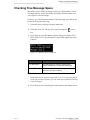
Checking Free Message Space . . . . . . . . . . . . . . . . . . . . . . . . . . . . . . . 5–39
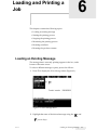
Chapter 6 — Loading and Printing a Job
Loading an Existing Message . . . . . . . . . . . . . . . . . . . . . . . . . . . . . . . . . 6–1
Starting the Printing Process. . . . . . . . . . . . . . . . . . . . . . . . . . . . . . . . . . 6–2
Stopping the Printing Process. . . . . . . . . . . . . . . . . . . . . . . . . . . . . . . . . 6–2
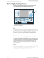
Monitoring the Printing Process . . . . . . . . . . . . . . . . . . . . . . . . . . . . . . 6–3
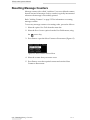
Resetting Message Counters . . . . . . . . . . . . . . . . . . . . . . . . . . . . . . . . . . 6–4
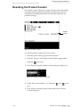
Resetting the Product Counter . . . . . . . . . . . . . . . . . . . . . . . . . . . . . . . . 6–5
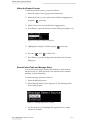
Hiding the Product Counter . . . . . . . . . . . . . . . . . . . . . . . . . . . . . . 6–6
External Select Table and Message Select . . . . . . . . . . . . . . . . . . . 6–6
Chapter 7 — Line Setup
Triggering a Print . . . . . . . . . . . . . . . . . . . . . . . . . . . . . . . . . . . . . . . . . . . 7–1
Printing Manually. . . . . . . . . . . . . . . . . . . . . . . . . . . . . . . . . . . . . . . 7–1
Printing with a Product Detector . . . . . . . . . . . . . . . . . . . . . . . . . . 7–2
Print Acknowledge. . . . . . . . . . . . . . . . . . . . . . . . . . . . . . . . . . . . . . 7–3
Set Language . . . . . . . . . . . . . . . . . . . . . . . . . . . . . . . . . . . . . . . . . . . 7–4
Printing Continuously . . . . . . . . . . . . . . . . . . . . . . . . . . . . . . . . . . . 7–4
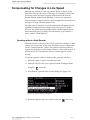
Compensating for Changes in Line Speed . . . . . . . . . . . . . . . . . . . . . . 7–6
Operating without a Shaft Encoder . . . . . . . . . . . . . . . . . . . . . . . . 7–6
Configuring the Printer to Use a Shaft Encoder. . . . . . . . . . . . . . 7–7
Chapter 8 — Maintenance
Conducting Routine Inspection and Cleaning. . . . . . . . . . . . . . . . . . . 8–1
Visually Inspecting the Printer . . . . . . . . . . . . . . . . . . . . . . . . . . . . 8–1
Inspecting and Cleaning the Printhead. . . . . . . . . . . . . . . . . . . . . 8–2
Inspecting and Replacing the Fan Filter . . . . . . . . . . . . . . . . . . . . 8–6
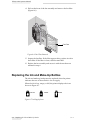
Replacing the Ink and Make-Up Bottles . . . . . . . . . . . . . . . . . . . . . . . . 8–8
Scheduling the Printer Service . . . . . . . . . . . . . . . . . . . . . . . . . . . . . . . 8–10
Viewing the Run Hour Timers . . . . . . . . . . . . . . . . . . . . . . . . . . . . . . . 8–10
Taking Backup of Printer Configuration . . . . . . . . . . . . . . . . . . . . . . 8–12
Rev AC
vii
Videojet 1310 Operator Manual
Taking a Backup . . . . . . . . . . . . . . . . . . . . . . . . . . . . . . . . . . . . . . . 8–12
Taking a Full System Backup of System Settings . . . . . . . . . . . . 8–13
Restoring Printer Settings . . . . . . . . . . . . . . . . . . . . . . . . . . . . . . . . . . . 8–13
Restoring Printer Settings from Backup . . . . . . . . . . . . . . . . . . . 8–13
Restoring Printer Settings from Full System Backup. . . . . . . . . 8–14
Chapter 9 — Troubleshooting
Troubleshooting Overview . . . . . . . . . . . . . . . . . . . . . . . . . . . . . . . . . . . 9–1
Troubleshooting Power Problems . . . . . . . . . . . . . . . . . . . . . . . . . 9–2
Troubleshooting the Amber LED . . . . . . . . . . . . . . . . . . . . . . . . . . 9–2
Printer is On, But Does Not Print . . . . . . . . . . . . . . . . . . . . . . . . . . 9–3
Problems with Print Position or Size . . . . . . . . . . . . . . . . . . . . . . . 9–4
Poor Print Quality . . . . . . . . . . . . . . . . . . . . . . . . . . . . . . . . . . . . . . . 9–4
Printer Status Icons . . . . . . . . . . . . . . . . . . . . . . . . . . . . . . . . . . . . . . 9–4
Fault and Warning Messages . . . . . . . . . . . . . . . . . . . . . . . . . . . . . 9–8
List of Faults and Warnings. . . . . . . . . . . . . . . . . . . . . . . . . . . . . . . 9–9
Checking the Software Version. . . . . . . . . . . . . . . . . . . . . . . . . . . . . . . 9–12
Appendix A — Specifications
Physical Specifications . . . . . . . . . . . . . . . . . . . . . . . . . . . . . . . . . . . . . .
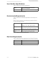
User Interface Specifications . . . . . . . . . . . . . . . . . . . . . . . . . . . . . . . . .
Environmental Requirements . . . . . . . . . . . . . . . . . . . . . . . . . . . . . . . .
Electrical Requirements . . . . . . . . . . . . . . . . . . . . . . . . . . . . . . . . . . . . .
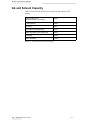
Ink and Solvent Capacity. . . . . . . . . . . . . . . . . . . . . . . . . . . . . . . . . . . .
A–1
A–3
A–3
A–3
A–4
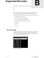
Appendix B — Supported Barcodes
Barcode Setup . . . . . . . . . . . . . . . . . . . . . . . . . . . . . . . . . . . . . . . . . . . . . .B–1
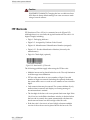
ITF Barcode . . . . . . . . . . . . . . . . . . . . . . . . . . . . . . . . . . . . . . . . . . . . . . . .B–2
EAN-8 Barcode . . . . . . . . . . . . . . . . . . . . . . . . . . . . . . . . . . . . . . . . . . . . .B–3
EAN-13 Barcode . . . . . . . . . . . . . . . . . . . . . . . . . . . . . . . . . . . . . . . . . . . .B–4
UPC A Barcode . . . . . . . . . . . . . . . . . . . . . . . . . . . . . . . . . . . . . . . . . . . . .B–5
Code 128 Barcode . . . . . . . . . . . . . . . . . . . . . . . . . . . . . . . . . . . . . . . . . . .B–6
EAN-128 Barcode . . . . . . . . . . . . . . . . . . . . . . . . . . . . . . . . . . . . . . . . . .B–10
Code 39 Barcode . . . . . . . . . . . . . . . . . . . . . . . . . . . . . . . . . . . . . . . . . . .B–11
Appendix C — Serial Communications
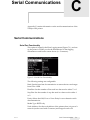
Serial Communications . . . . . . . . . . . . . . . . . . . . . . . . . . . . . . . . . . . . .
Serial Port Functionality. . . . . . . . . . . . . . . . . . . . . . . . . . . . . . . . .
Serial Port Baud Rates . . . . . . . . . . . . . . . . . . . . . . . . . . . . . . . . . .
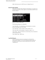
Log Onto Remote . . . . . . . . . . . . . . . . . . . . . . . . . . . . . . . . . . . . . .
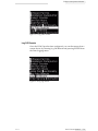
Log Off Remote . . . . . . . . . . . . . . . . . . . . . . . . . . . . . . . . . . . . . . . .
viii
C–1
C–1
C–2
C–2
C–3
Rev AC
1
Introduction
This chapter contains the following topics:
• A description regarding the intended use of the product
• Information about the audience to whom this manual is targeted
• A description of how the manual is organized
• Information regarding other manuals that are associated with this
printer
Caution
EQUIPMENT DAMAGE. Read Chapter 2, “Safety” before
attempting to operate the equipment.
Equipment Description
The Videojet 1310 printer is a non-contact, ink jet printer that prints at
high production speed onto almost all surfaces, in any required
direction.
Printer Supplies
A large variety of Videojet inks are available for use along with this
product. Consult your Videojet Technologies sales representative for
questions regarding the supplies selection (inks, make-up fluids, and
cleaning solutions) or product applications.
Caution
EQUIPMENT DAMAGE. Only Videojet supplies are
recommended for use in this printer. Non-approved supplies
may damage the printing unit, thus producing inferior printing
operations or printing output.
Rev AC
Equipment Description
1-1
Videojet 1310 Operator Manual
About this Manual
The Videojet 1310 operator's manual is intended for the operator and
contains information only for operating the printer. Unless noted
otherwise, all procedures in this manual can be performed by the
operator of the printer.
The operator's manual is a supplement to (and not a replacement for)
formal training.
Related Documents
The Videojet 1310 Service Manual (P/N 361541) is the other document
that is available (through Videojet Customer Service), for the Videojet
1310 printer.
The service manual contains information on installing, maintaining,
troubleshooting, and servicing the Videojet 1310 printer. It also
includes sections about the theory of operation, component
identification, and the illustrated parts breakdown of the printer.
This document is intended for use only by trained service personnel.
The service manual is a supplement to (and not a replacement for)
formal training.
Caution
EQUIPMENT DAMAGE. Customers who intend to service and
maintain the printer themselves must have only qualified
personnel perform these procedures. Qualified personnel have
successfully completed the training courses, have sufficient
experience with this printer, and are aware of the potential
hazards to which they may be exposed.
1-2
About this Manual
Rev AC
Videojet 1310 Operator Manual
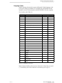
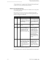
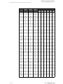
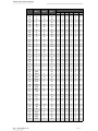
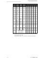
Language Codes
While ordering for manuals, ensure adding the 2-digit language code
to the end of the part number. For example, the part number for the
Spanish version of this manual would be 361540-04. For the complete
list of codes, refer Table 1-1.
Code
Language
Availability (see Note)
01
English (US)
*
02
French
*
03
German
*
04
Spanish
*
05
Portuguese (Brazil)
*
06
Japanese
*
07
Russian
08
Italian
09
Dutch
10
Chinese (Simplified)
11
Arabic
12
Korean
13
Thai
14
Icelandic
15
Norwegian
16
Finnish
17
Swedish
18
Danish
19
Greek
20
Hebrew
21
English (UK)
23
Polish
+
*
*
*
+
Table 1-1: Language Codes List
Note: Initial availability of the Operator’s Manual is indicated by an asterisk
(*). Availability of the Service Manual is indicated by a plus sign (+).
Rev AC
About this Manual
1-3
2
Safety
This chapter contains the following topics:
• Safety conventions used throughout this manual
• Important safety guidelines to follow while operating the
equipment
• Important safety guidelines to follow while working with inks,
make-up fluids, and cleaning solutions
• Action to be taken in case of a medical emergency
Caution
EQUIPMENT DAMAGE. Read this chapter thoroughly before
attempting to install, operate, service, or maintain this product.
Introduction
The policy of Videojet Technologies Inc. is to manufacture non-contact
printing/coding systems and ink supplies that meet high standards of
performance and reliability. Therefore, we employ strict quality
control measures to eliminate the potential for defects and hazards in
our products.
The intended use of this printer is to print information directly onto a
product. Use of this equipment for any other purpose may lead to
serious personal injury.
The safety guidelines provided in this chapter are intended to educate
the operator on all safety issues so that the operator can operate the
printer safely.
Rev AC
Introduction
2-1
Videojet 1310 Operator Manual
Safety Conventions Used in the Manual
Specific safety information are listed throughout this manual in the
form of Warning and Caution statements. Pay close attention to these
statements as they contain important information that help in
avoiding potential hazards to yourself or to the equipment.
Warning Statements
• Warning statements are used to indicate hazards or unsafe
practices that may result in personal injury or death.
• They have a triangular symbol with an exclamation mark to the
immediate left of the text.
• They are always preceded by the word “Warning”.
• They are always found before the step or information referring to
the hazard.
For example:
Warning
PERSONAL INJURY. The next step, “Cleaning the Printhead,”
must be performed by the service or maintenance personnel.
Qualified personnel have successfully completed the training
courses, have sufficient experience with this printer, and are
aware of the potential hazards to which they may be exposed.
Caution Statements
• Caution statements are used to indicate hazards or unsafe
practices that can result in product or property damage.
• They have a triangular symbol with an exclamation mark to the
immediate left of the text.
• They are always preceded by the word “Caution”.
• They are always found before the step or information referring to
the hazard.
2-2
Safety Conventions Used in the Manual
Rev AC
Videojet 1310 Operator Manual
For example:
Caution
EQUIPMENT DAMAGE. Never turn off the printer by switching
the AC power switch to the Off (O) position. Before pressing the
Off key, allow the printer to complete the three and a half minute
shutdown sequence. Failure in following this procedure
prevents the printer from drawing the ink in the ink return line,
back into the reservoir. This may cause the ink to dry in the ink
return line, resulting in problems when you turn the printer on
again.
Equipment Safety Guidelines
This section contains important safety guidelines pertaining to the
operation and handling of the printer and associated equipment.
Warning
PERSONAL INJURY. Always observe the following safety
guidelines while operating and handling the printer and
associated equipment.
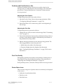
Comply with Electrical Codes
All electrical wiring and connections must comply
with the applicable local codes. Consult the
appropriate regulatory agency for more information.
Avoid Breathing Exhaust Vapors
During its operation, the printer releases fumes from
the printer exhaust tube. These fumes may be
flammable and present a health hazard. For these
reasons, do not allow the exhaust to be confined to an
area that does not have proper ventilation, or is
located near a source of ignition. Printer exhaust
fumes are generally heavier than air, so keep all
sources of ignition away from low areas where the fumes may travel
or accumulate.
If, under any circumstances, the printer is to be kept in a place that
Rev AC
Equipment Safety Guidelines
2-3
Videojet 1310 Operator Manual
lacks proper ventilation, it is necessary to expel the printer exhaust to
the outside air. Consult the appropriate regulatory agency in concern
with the emission permit and venting system requirements, before
giving vent to the printer exhaust into the outside air.
Note: A Vapor Exhaust Ducting Kit is available at Videojet Technologies
Inc.
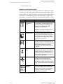
Do Not Remove Warning Labels
Do not, under any circumstances, remove or
obstruct any warning, caution, or instruction labels
present on the printer.
Placement of the Printer
Warning
PERSONAL INJURY. Do not place the printer in a hazardous
location. Hazardous locations might create an explosion, leading
to personal injury.
Hazardous locations, as defined in the United States, are those areas
that may contain hazardous materials in a quantity sufficient to create
an explosion. These are defined in Article 500 of the National Electrical
Code ANSI/NFPA 70–1993.
Outside the United States, you must ensure compliance with all local
regulations regarding equipment placement in potentially hazardous
locations.
Location of the AC Socket-Outlet
To maintain regulatory approval (EN 60950-01, Sec 1.7.2), the AC
socket-outlet must be near the printer, and should be easily accessible.
Mounting the Printhead Stand
To maintain regulatory approval, the printhead stand should be bolted
to the floor, conveyor, or any other stable foundation when installed.
2-4
Placement of the Printer
Rev AC
Videojet 1310 Operator Manual
Using Printer Accessories
To maintain regulatory approval for the printer, you must use only
Videojet-approved accessories when attaching any device to the
equipment.
The following printer stands have been approved:
• Mobile Floor Stand (P/N-378766)
• Stationery Floor Stand (P/N-378155)
• Table Top Stand (P/N-378158)
Rev AC
Placement of the Printer
2-5
Videojet 1310 Operator Manual
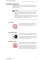
Ink Safety Guidelines
This section provides important safety guidelines pertaining to the
usage and handling of printer supplies (inks, make-up fluids, and
cleaning solutions).
Warning
PERSONAL INJURY. Observe the following safety guidelines
while using or handling inks, make-up fluids, and cleaning
solutions.
For continued protection against a possible fire hazard, use only
Videojet supplies having a flash point not lower than -22°C (-8°F)
and boiling point not lower than 56°C (133°F).
No Smoking
Do not smoke near the printer or printhead. If the
printer exhaust fumes are subjected to an ignition
source, it may result in an explosion or fire.
Wear Safety Glasses
Wear safety glasses with side shields (or equivalent
eye protection) when handling any ink, make-up
fluid, or cleaning solution. If it splashes onto your
eyes, flush your eyes with water for 15 minutes and
consult a physician immediately.
Avoid Skin Contact
Wear butyl rubber gloves while handling the ink,
make-up fluid, or cleaning solution. Avoid contact
with skin and mucous membranes (nasal passage,
throat). On contact with the skin, remove any
contaminated clothing and wash the area with soap
and water. Consult a physician if irritation persists.
2-6
Ink Safety Guidelines
Rev AC
Videojet 1310 Operator Manual
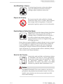
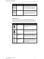
Avoid Breathing in Vapors
Avoid prolonged exposure to the print exhaust
vapors. If respiratory protection is needed, a
cartridge organic respirator can be used.
Dispose Ink Properly
Do not pour any ink, make-up fluid, or cleaning
solution into sinks, sewers, or drains. Waste disposal
must comply with local regulations. Contact the
appropriate regulatory agency for more information.
Read the Material Safety Data Sheets
Read and understand the Material Safety Data Sheet
(MSDS) before using any ink, make-up fluid, or
cleaning solution. An MSDS exists for each type of
ink, make-up fluid, and cleaning solution. The
appropriate sheet or sheets are supplied along with
the shipped product.
Ensure that you retain all MSDSs for future reference in case you need
to consult a physician regarding an ink-related accident. Additional
copies of MSDSs are available on request, and can be obtained by
contacting the Videojet Customer Service Department at 800–843–
3610. Outside the U.S, customers should contact a subsidiary Videojet
office or their local Videojet distributor.
Store the Inks Properly
Certain inks, make-up fluids, and cleaning solutions
are flammable and must be stored appropriately.
Storage must comply with local regulations. Contact
the appropriate regulatory agency for more
information. The label on the bottle or the MSDS
indicates if a particular fluid is flammable or not.
Caution
EQUIPMENT DAMAGE. The waste container or service tray
grounded to the printhead must be made of metal. Use of a nonmetallic waste container/service tray may result in possible
electrostatic discharge.
Rev AC
Ink Safety Guidelines
2-7
Videojet 1310 Operator Manual
Medical Emergencies
This section provides important medical information in case of an
accident.
Warning
PERSONAL INJURY. In the event of a medical emergency,
contact a physician immediately.
Emergencies Involving Printer Fluids
If the incident involves an ink, make-up fluid, or cleaning solution,
carry the bottle and/or MSDS with you to the physician’s office. These
items contain important information that the physician may require in
order to provide the precise medical treatment.
Rocky Mountain Poison Control Center
All of Videojet inks, make-up fluids, and cleaning solutions are also
registered with the Rocky Mountain Poison Control Center, located in
the United States. If the bottle or MSDS cannot be located, the
physician can contact the Rocky Mountain Poison Control Center to
obtain the information required.
Rocky Mountain Poison Control Center
(303) 623-5716
Note: Persons outside the United States requiring medical attention can have
a physician contact the Rocky Mountain Poison Control Center in the United
States or a poison control center or hospital in their own area.
2-8
Medical Emergencies
Rev AC
3
Main Parts
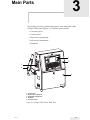
This chapter provides a detailed description of the main parts of the
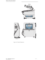
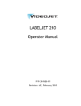
Videojet 1310 printer (Figure 3-1). The main parts include:
• Connector panel
• Control panel
• Electronics compartment
• Ink system compartment
• Printhead
1
2
5
4
3
1. Control Panel
2. Electronics Compartment
3. Ink System Compartment
4. Printhead
5. Connector Panel
Figure 3-1: Videojet 1310 Printer Main Parts
Rev AC
3-1
Videojet 1310 Operator Manual
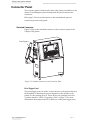
Connector Panel
The connector panel is located at the side of the printer. In addition to the
mount for installing the optional lamp stack, the panel contains nine
connectors.
Refer page 3-3 for more information on the standard and optional
connectors present on the panel.
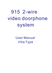
Standard Connector
Figure 3-2 shows the standard connector on the connector panel of the
Videojet 1310 printer.
Print Trigger 1
Figure 3-2: Standard Connector on the Connector Panel
Print Trigger Port 1
The print trigger ports are used to connect devices to the printer that have
the capability of detecting the precise alignment of the product to the
printer, for the printing process. These devices are generally known as
“product detectors.” Refer “Triggering a Print” on page 7-1 for more
information about when and how to make use of the print trigger ports.
3-2
Connector Panel
Rev AC
Videojet 1310 Operator Manual
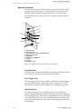
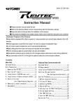
Optional Connectors
The optional connectors on the connector panel of the Videojet 1310
printer are shown in Figure 3-3. All the optional connectors are not
installed on the standard Videojet 1310 printer. Your printer may
contain some of the connectors in order to support specific optional
functions.
1
2
3
9
8
7
4
5
6
1. Lamp Stack Port
2. Print Trigger 2 Port
3. Alarm Relay Port or Opto-isolated Output Port
4. Basic Input/Output Port
5. COMM 1 Port
6. RS-485 Port or COMM 2 Port
7. I/O B Port
8. I/O A Port
9. Shaft Encoder Port
Figure 3-3: Optional Connectors on the Connector Panel
Lamp Stack Port
The lamp stack connector and the three mounting holes that surround
it are used to install the optional lamp stack assembly.
Print Trigger Port 2
The print trigger port 2 (3-pin, female) is identical to the print trigger
port 1 in function. Refer “Triggering a Print” on page 7-1 for more
information on when and how to make use of the print trigger ports.
Alarm Relay Port
The alarm relay port (7-pin, female) comprises two outputs that
produce signals indicating problems that may prevent the completion
of the printing process. This feature is identical to the relay option that
was available in the 43s, 46 series, and Willett 400 series printers. The
alarm relay port requires the optional I/O expansion circuit board for
its installation.
Rev AC
Connector Panel
3-3
Videojet 1310 Operator Manual
Opto-isolated Output Port
The opto-isolated output port (8-pin, female) is reserved for special
applications. It requires the optional I/O expansion circuit board for
its installation.
Basic Input/Ouput Port
The basic input/output (5-pin, female) connector performs two
functions:
• The first is to produce an output signal that is indicative of when
the printer is able to print. This signal is useful for applications
that require some external action when the printer can no longer
print. For example, some customers would like their production
line to stop when the printer fails.
• The second function is a logic input that is reserved for special
applications.
COMM 1 and COMM 2 Port
The COMM 1 and COMM 2 (6-pin, COMM 1 is male, COMM 2 is
female) are RS-232 serial ports. The COMM 1 port can be used for the
handheld barcode scanner option or used to produce an
acknowledgement every time a message is printed successfully.
Alternatively, COMM 2 can interface with Videojet’s Connector
software.
RS-485 Port
The RS-485 (3-pin, male) is a serial port. It is typically used to interface
with Videojet’s Connector software.
I/O A and I/O B Port
The I/O A and I/O B (8-pin, female) are optional ports that provide
the same external message select facility that was available as an
option in the 43s, 46 series, and Willett 400 series printers. Use these
ports if you are replacing one of these printer models with an
application that makes use of the external message select function. The
I/O A and I/O B ports require the optional I/O expansion circuit
board for their installation.
Shaft Encoder Port
The shaft encoder port (4-pin, female) may be used to connect a shaft
encoder to the printer. Shaft encoders sense changes in the line speed,
allowing the printer to compensate the change in the line speed with a
change in the print speed. Refer “Compensating for Changes in Line
Speed” on page 7-6 for more information on the use of a shaft encoder.
3-4
Connector Panel
Rev AC
Videojet 1310 Operator Manual
Control Panel
The control panel handles the overall control, data input and output,
and the user interface of the printer. The decisions regarding the
initiation of various functions are made by the control software
residing on this board. The functions are carried out by the circuitry
residing on the print engine board.
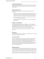
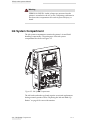
Electronics Compartment
The electronics compartment contains the printer’s power supply and
control electronics. The main parts of the electronics compartment are
shown in Figure 3-4.
1
2
3
4
1. Cooling Fan
2. Control and Print Engine Circuit Board
3. Power Supply Unit (PSU)
4. Display Circuitry
Figure 3-4: Electronics Compartment
Only Videojet-trained service personnel should attempt to access the
electronics compartment of the printer.
Rev AC
Control Panel
3-5
Videojet 1310 Operator Manual
Warning
PERSONAL INJURY. Lethal voltages are present when the
printer is connected to the AC power. Tampering with items in
the electronics compartment can result in personal injury or
death.
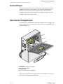
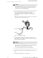
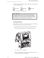
Ink System Compartment
The ink system compartment contains the printer’s air and fluidhandling componentry. The main parts of the ink system
compartment are shown in Figure 3-5.
Figure 3-5: Ink System Compartment
The ink bottle and make-up bottle requires occasional replacement
during normal operation. Refer “Replacing the Ink and Make-Up
Bottles” on page 8-8 for more information.
3-6
Ink System Compartment
Rev AC
Videojet 1310 Operator Manual
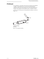
Printhead
The printhead is connected to the electronics cabinet by the umbilical
assembly. The printhead receives pressurized ink through the
umbilical and turns the ink stream into tiny electrically-charged ink
droplets. The droplets are then deflected onto a substrate to form a
printed code. The main parts of the printhead assembly are shown in
Figure 3-6.
1
2
1. Umbilical Assembly
2. Printhead
Figure 3-6: Printhead Assembly
Rev AC
Printhead
3-7
Getting Started
4
This chapter contains the following topics:
• Starting the printer
• Working with the user interface
• Entering and changing the password
• Changing the displayed language
• Setting the system time and date
• Setting up shifts
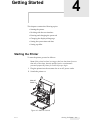
Starting the Printer
To start the printer, proceed as follows:
Note: If the printer has been in storage or has been shut down for more
than two or three days, have the qualified service or maintenance
personnel prepare the printer for service before you begin.
1 Plug the printer into the accurate slot on an AC power outlet.
2 Switch the printer on.
Main AC
Switch
Figure 4-1: Main AC Switch
Rev AC
Starting the Printer
4-1
Videojet 1310 Operator Manual
Wait for the printer to complete initializing and the default screen
(Figure 4-2) to appear.
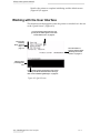
Working with the User Interface
The default screen that appears when the printer is switched on is known
as the “Quick Screen” (Figure 4-2).
Icons representing faults, warnings and
general printer status appears here. Refer
“Printer Status Icons” on page 9-4.
Function Key
Summary
Refer “Function
Keys” on
page 4-3.
The total number of
products detected. Refer
“Resetting the Product
Counter” on page 6-5.
Message to be
printed appears
here
Printer status appears at the bottom of the screen.
This may include text-based faults and warnings.
Refer “Fault and Warning Messages” on page 9-8.
Figure 4-2: Quick Screen
4-2
Working with the User Interface
Rev AC
Videojet 1310 Operator Manual
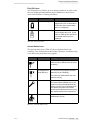
Function Keys
The four function keys on the left side of the display allows easy access
to the major printer control functions.
Key
Function
f1
Start or stop the ink jet (start and stop printing). Refer
“Starting the Printing Process” on page 6-2 and
“Stopping the Printing Process” on page 6-2.
f2
Select a message to print. Refer “Loading an Existing
Message” on page 6-1.
f3
Display the menu bar at the top of the screen. Press this
key again to hide the menu bar. Refer “Menu Bar” on
page 4-3.
f4
Edit the message selected currently. Refer Chapter 5,
“Creating a Job” for more information.
Table 4-1: Function Keys
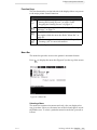
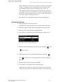
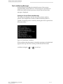
Menu Bar
The menu bar provides access to the printer’s advanced features.
Press f3
to display the menu bar (Figure 4-3) at the top of the screen.
Figure 4-3: Menu Bar
Selecting a Menu
The menu bar contains nine menus and only a few are displayed at
any given time. However, the menu bar scrolls left and right to reveal
the hidden ones. To select a particular menu from the bar, proceed as
follows:
Rev AC
Working with the User Interface
4-3
Videojet 1310 Operator Manual
1 Highlight the desired option using the
and
arrow
keys.
2 Press Enter to open the highlighted menu.
Note: If a menu title has one character highlighted, you can open the
desired menu by holding down the Alt key and then pressing the
highlighted character in the menu’s title, on the keypad. The display of
the highlighted characters may vary based on the display language
selected.
Selecting an Item from the Open Menu
To select an item from an open menu, proceed as follows:
1
Highlight the desired option from the open menu using the
and
arrow keys.
2 Press Enter to open the highlighted option.
Note: Each menu shows only those options that are available at the
current access level. Refer “Entering and Changing Passwords” on
page 4-6 for more information on advanced access levels.
Note: If a menu item has one character highlighted, you can select a
desired item by pressing the highlighted character on the keypad. The
display of the highlighted characters may vary based on the display
language selected.
Exiting a Menu
To exit a menu without making a selection, press the Esc key.
4-4
Working with the User Interface
Rev AC
Videojet 1310 Operator Manual
Dialog Boxes
Figure 4-4: Dialog Box
To modify the contents of a dialog box (Figure 4-4), proceed as follows:
1 Highlight the desired option, using the
and
arrow
keys.
2 Adjust the displayed value for the selected field, using one of the
methods given below:
• Cycle through the available values using the
and
arrow keys. This feature works with numerical fields, check
boxes, and some text fields.
• Type the desired value. This feature works with numerical
fields and some text fields.
• Press the space bar to switch a check box on or off. This feature
works for check boxes only.
3 Repeat steps 1 and 2 for each additional field that is to be edited.
4 Exit the dialog box by following one of the procedures given
below:
• Press Enter to save all the changes and exit the dialog box.
• Press Esc to exit the dialog box without saving the changes.
Rev AC
Working with the User Interface
4-5
Videojet 1310 Operator Manual
Entering and Changing Passwords
The printer has several access levels. The default level (0) allows access
only to a few features, such as the ability to start and stop printing or
to select a different message. Advanced access levels allow features
such as message creation and printer setup. The entry to higher access
levels requires the entry of a level 1 or a level 2 password. By entering
the password for a particular level, the operator gains access to the
features for that access level, as well as for all the lower levels.
Note: All the software features covered from this point in the book, require the
entry of a password. If a feature described in the book does not appear in the
software menus, you are currently at a password level that is not high enough
to access that feature.
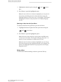
Entering a Password
To enter a password for a particular access level, proceed as follows:
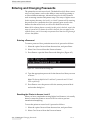
1 Select the option Password from the menu bar, and press Enter.
2 Select Enter Password from the Password menu.
3 Press Enter to open the Enter Password dialog box (Figure 4-5).
Figure 4-5: Enter Password Dialog Box
4 Type the appropriate password for the feature level that you want
to access.
Note: The factory default level 1 and level 2 passwords are 1111 and
2222 respectively.
5 Press Enter to save the password for the current password level
and exit the dialog box.
Resetting the Printer to Access Level 0
When you have completed accessing higher level features, it is usually
better to return the printer to access level 0 in order to prevent
unauthorized tampering.
To reset the printer to access level 0, proceed as follows:
1 Select the option Password from the menu bar, and press Enter.
2 Select Clear Password from the Password menu.
4-6
Entering and Changing Passwords
Rev AC
Videojet 1310 Operator Manual
3 Press Enter to clear the password for the higher access levels and
exit the dialog box.
Note: This option does NOT remove or change any password stored in
the system.
Changing the Passwords for Levels 1 and 2
The passwords used to access level 1 and level 2 features can be
changed when required. However, you must enter a password of
equal or higher access level first. In other words, you must be at access
level 1 (or higher) in order to change the password for access level 1.
To change the password of the required access level, proceed as
follows:
1 Select the option Password from the menu bar, and press Enter.
2 Select Set Password for Level 1 or Set Password for Level 2 from the
Password menu.
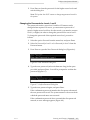
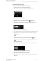
3 Press Enter to open the New Password dialog box (Figure 4-6).
Figure 4-6: New Password Dialog Box
4 Type the new password (at least 4 characters long) in the space
provided, and press Enter. You will be prompted to confirm the
password (Figure 4-7).
Figure 4-7: Confirm Password Dialog Box
5 Type the new password again, and press Enter.
If the confirmation password matches the first password entered,
the new password is saved. The system returns to the screen from
which the password menu was accessed.
If the confirmation password does not match the first password
entered, an error message appears (Figure 4-8).
Rev AC
Entering and Changing Passwords
4-7
Videojet 1310 Operator Manual
Figure 4-8: Change Password Dialog Box
Press any key to close the error message and return to the new
password window.
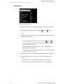
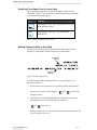
Changing the Displayed Language
The printer menus and prompts can be displayed in a number of
different languages.
To change the language of the printer menu display, proceed as
follows:
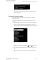
1 Select the option Configure from the menu bar, and press Enter.
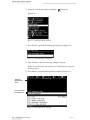
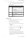
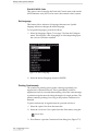
2 Select Set Language from the Configure menu. A list of all the
languages that are supported by the interface appears (Figure 4-9).
Figure 4-9: Set Language Screen
3 Select the desired language using the
and
arrow keys.
4 Press Enter to display the Menu screen in the language that you
set.
Note: Most of the printers require access level 2 to perform this task.
4-8
Entering and Changing Passwords
Rev AC
Videojet 1310 Operator Manual
Setting the System Time and Date
The printer’s internal clock can be configured as required. The options
available are:
• Setting the time of the day (in hours, minutes and seconds)
• Setting the date according to the Gregorian calendar used by the
western countries
• Choosing the day of the week to be designated as day 1
• Setting the date according to the Hejra calendar used in Arabic
countries
Note: Most of the printers require access level 2 to perform these tasks.
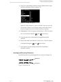
Setting the Time and Date - Gregorian Calendar
To set the time of the day and date according to the Gregorian
calendar, proceed as follows:
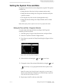
1 Select the option Configure from the menu bar, and press Enter.
2 Select Set Time/Date from the Configure menu.
3 Press Enter to open the Set Time/Date dialog box (Figure 4-10 on
page 4-9).
Figure 4-10: Set Time/Date Dialog Box
4 Select a field to edit using the
and
arrow keys.
5 Change the value of the selected field either by using the
and
arrow keys, or by typing the desired value in place of the
old.
Note: The value for the Date field can be changed by, not more than 2
days at a time. If the date is changed by more than two days, repeat this
step until the time and date are correct.
6 Repeat steps 4 and 5 to edit any other field.
Rev AC
Setting the System Time and Date
4-9
Videojet 1310 Operator Manual
Note: Week Rollover Day specifies the day of the week that is designated
as day 1. For example, if you select Monday as the week rollover day,
then Tuesday is day 2 each week, Wednesday is day 3, and so on.
This setting also affects how the printer calculates the week of the year.
For example, if you select the Week Rollover Day as Sunday and the new
year begins on a Wednesday, then week 1 starts on Wednesday, January
1, but week 2 begins on Sunday, January 5.
7 Press Enter to save the time and date and exit the dialog box.
Setting the Hejra Date
To set the Hejra date, proceed as follows:
1 Configure the Gregorian date before configuring the Hejra date.
2 Select the option Configure from the menu bar, and press Enter.
3 Select Set Hejra Date from the Configure menu.
4 Press Enter to open the Set Hejra Date dialog box (Figure 4-11).
Figure 4-11: Set Hejra Date Dialog Box
5 Select the required field (day, month, or year) using the
and
arrow keys.
6 Change the value of the selected field either by using the
and
arrow keys or by typing the desired value in place of
the old.
7 Repeat steps 5 and 6 to edit any other field.
8 Press Enter to set the date and exit the dialog box.
Note: When you change the Gregorian date, the printer automatically
changes the Hejra date by the same number of days, months, and years.
4-10
Setting the System Time and Date
Rev AC
Videojet 1310 Operator Manual
Setting Up Shifts
If shift codes are being used in messages, the shifts have to be defined
first.
To set up shifts, proceed as follows:
1 Select the option User Fields from the menu bar, and press Enter.
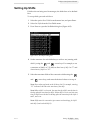
2 Select Set Shifts from the User Fields menu.
3 Press Enter to open the Set Shifts dialog box (Figure 4-12).
Figure 4-12: Set Shifts Dialog Box
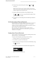
4 Set the start time for each shift that you wish to use (starting with
shift 1), using the
and
arrow keys. For example, to set
a start time of shift 1 as 7:15 AM, set Start hour of shift 1 to “7” and
Start minute of shift 1 to “15”.
5 Select the start time fields of the consecutive shifts using the
and
arrow keys, and enter the desired values as in step 4.
Note: Hour values are based on the 24-hour clock. For example, entering
“15” indicates 3:00 PM as the start time of the shift.
Note: When shift 2 is to be used, the start time for shift 2 must be later in
the day, after the start time for shift 1. When shift 3 is to be used, the start
time for shift 3 must be later in the day, after the start time for the shifts 1
and 2, and so on.
Note: Shifts must be consecutive (you cannot set the timings for shift 1
and shift 3, and exclude Shift 2).
Rev AC
Setting Up Shifts
4-11
Videojet 1310 Operator Manual
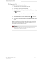
6 Enter “0” for both the start hour and the start minute of the first
shift you do not wish to use. The shifts that follow are not used.
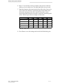
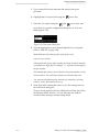
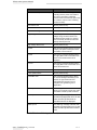
7 Enter the character that represents the first shift in the Character for
shift 1 field. This character, representing the current shift can be
inserted in messages at the time of print. The printer counts
upward from that character onwards to derive the remaining shift
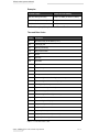
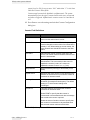
codes. Table 4-2 provides an example of shift codes.
Value Entered
Shift 1
Shift 2
Shift 3
Shift 4
Shift 5
A
A
B
C
D
E
1
1
2
3
4
5
4
4
5
6
7
8
d
d
e
f
g
h
Table 4-2: Shift Codes
8 Press Enter to save the settings and exit the Set Shifts dialog box.
4-12
Setting Up Shifts
Rev AC
5
Creating a Job
This chapter contains the following topics:
• Creating a new message
• Formatting text
• Copying and pasting text
• Inserting foreign language characters
• Inserting a barcode
• Working with user fields
• Adding a prompted field
• Adding clock and calendar information
• Adding counters
• Adding logos and other graphics
• Configuring message parameters
• Copying messages
• Deleting messages
• Checking free message space
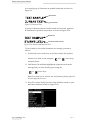
Creating a New Message
To create a new message, proceed as follows:
1 Select the option Messages from the menu bar (refer “Menu Bar”
on page 4-3 for instructions).
Rev AC
Creating a New Message
5-1
Videojet 1310 Operator Manual
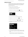
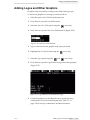
2 Select the New Message option, using the
arrow key
(Figure 5-1).
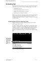
Figure 5-1: Messages Menu Options
3 Press Enter to open the New Message dialog box (Figure 5-2).
Figure 5-2: New Message Dialog Box
4 Type a name for the new message, using the keypad.
Note: The message name may contain up to 30 alphanumeric characters,
including spaces.
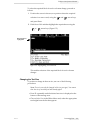
5 Press Enter to open the Message Editor window (Figure 5-3).
Typed text
appears at the
cursor
Current Font Size
is indicated here
Figure 5-3: Message Editor Window
5-2
Creating a New Message
Rev AC
Videojet 1310 Operator Manual
6 Enter a new message in the space provided. To enter a simple
(static text only) message, proceed as follows:
a. Press F1 repeatedly until the desired font size is displayed at the
bottom of the message area (Font field).
b. Type the message text in the space provided.
More complex message content and formatting can be achieved by
employing any of the following techniques:
• Modifying the attributes and formatting of individual blocks of
text (refer “Formatting Text” on page 5-4)
• Inserting barcodes (refer “Inserting a Barcode” on page 5-11)
• Inserting “user fields” (refer “Working with User Fields” on
page 5-13)
• Changing the message attributes (refer “Configuring Message
Parameters” on page 5-34)
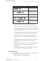
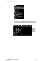
7 Press Shift + F1 when you complete editing the message.
This saves the new message and exits from the Message Editor
window.
Notes: “Save and Exit” from the Editor menu can also be used instead of
Shift + F1, to save the message and exit the window.
Save the created message so that the new version of the message is printed
immediately (starting with the next impression).
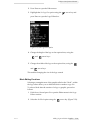
Entering Multiple Lines
Messages that are entered can be up to 32 dots high. You can enter
multiple lines of text, as long as all lines fit within the permissible
message height.
Start editing on a new line by moving the cursor to the line you want
to edit, using the
or
arrow key.
Note: Some Videojet printers require that you specify the number of lines of
text that are used in the message. This is not necessary on the Videojet 1310
printer. The printer automatically selects the best configuration based on the
actual message entered.
Rev AC
Creating a New Message
5-3
Videojet 1310 Operator Manual
Formatting Text
You can format the text in-line (as you type) or select and reformat an
entire block of text. The following formatting changes are possible:
• Changing the text size
• Switching from upper case to lower case
• Making the characters bold or very bold
• Inverting and reversing the characters
There are also other text formatting options (such as dot spacing) that
affect the entire message rather than just a portion of it. Refer
“Configuring Message Parameters” on page 5-34 for more information
on these settings.
Selecting a Block of Text to Change the Format
Using the selection procedure, formatting changes can be made to
affect an entire block of text.
To make formatting messages easier, the editor automatically selects
the block of text that you are currently typing. This is known as the
“default text selection” (Figure 5-4) and is displayed at the bottom of
the message display area (below the Font field). If no default text
selection is available, the message “No Text Selected” appears in that
area.
This bar indicates
the default text
selection. This is
the text that the
editor
automatically
selects as you
type.
Figure 5-4: Default Text Selection
5-4
Formatting Text
Rev AC
Videojet 1310 Operator Manual
To select the required block of text for a format change, proceed as
follows:
1 Position the cursor in the text, at a position where the required
selection is to start or end, using the
and
arrow keys,
and press Enter.
2 Hold down Ctrl and then highlight the required text using the
or
arrow keys (Figure 5-5).
New selection is
highlighted
Figure 5-5: Highlighting Text Selection
This enables selection of the required block of text for format
changes.
Changing the Text Size
To produce a change in the text size, use one of the following
procedures:
Note: Text size can only be changed in-line (as you type). You cannot
alter the size of text that you have already typed.
• Press F1 repeatedly until the desired text size is displayed at the
bottom of the message area.
• Choose Select Font in the Editor Menu and, select the appropriate
text height from the list that appears.
Rev AC
Formatting Text
5-5
Videojet 1310 Operator Manual
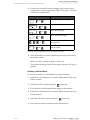
Switching From Upper Case to Lower Case
The required message may contain both upper and lower case
characters. Table 5-1 shows the keys on the keypad that control the
case of characters being typed.
Key
Function
Pressing the “caps” key changes the case of the
next character typed.
Pressing the “caps lock” key changes the
default case.
Table 5-1: Keys to Change Case of Text
Making Characters Bold or Very Bold
The text in the message can be made bold as the printer has the
capacity to print each column of dots two or three times.
Double dot
printing
Triple dot
printing
Figure 5-6: Making Bold Text
To make the text in the message bold or very bold (Figure 5-6),
proceed as follows:
1 Position the cursor in the text, at a position where the required
selection is to start or end, using the
and
arrow keys,
and press Enter.
2 Hold down Ctrl and then highlight the required text from the
message that you have already typed, using the
or
arrow keys.
Note: If no characters are selected, then the formatting changes affect the
new text typed at the cursor.
5-6
Formatting Text
Rev AC
Videojet 1310 Operator Manual
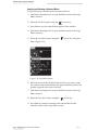
3 Press F3 or select Modify Attributes from the Editor menu to open
the Editor Attributes window (Figure 5-7).
Figure 5-7: Double Dot Option
Note: The “Inline Attributes” option in the Editor menu also opens the
same window. However, any formatting changes made, applies only to
the new text typed at the cursor and the selected text is ignored.
4 Highlight the Double Dot option (for bold text), or Triple Dot option
(for very bold text) using the
and
arrow keys.
5 Press the space bar to check the box alongside the selected
attribute.
6 Remove the check from either the Double Dot or Triple Dot option,
(as required) using the
and
arrow keys.
7 Press Enter to save the changes made and exit the Editor
Attributes window.
Inverting and Reversing Characters
Inverted characters are printed upside down as shown in Figure 5-8.
Normal Text
Inverted Text
Figure 5-8: Inverted Text
Rev AC
Formatting Text
5-7
Videojet 1310 Operator Manual
A reversed group of characters are printed backwards as shown in
Figure 5-9.
Normal Text
Reversed Text
Figure 5-9: Reversed Text
A group of characters that are both inverted and reversed, appear to
be rotated in an upside down position, as shown in Figure 5-10.
Normal Text
Inverted and Reversed Text
Figure 5-10: Inversed and Reversed Text
To invert and/or reverse the characters in a message, proceed as
follows:
1 Position the cursor in the text, at a position where the required
selection is to start or end, using the
and
arrow keys,
and press Enter.
2 Hold down Ctrl and then highlight the required text from the
message that you have already typed, using the
or
arrow keys.
Note: If no characters are selected, then the formatting changes effect the
new text typed at the cursor.
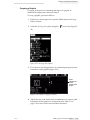
3 Press F3 or select Modify Attributes from the Editor menu to open
the Editor Attributes window (Figure 5-11).
Figure 5-11: Invert Option
5-8
Formatting Text
Rev AC
Videojet 1310 Operator Manual
Note: The “Inline Attributes” option in the Editor menu also opens the
same window. However, any formatting changes made applies only to the
new text typed at the cursor and the selected text is ignored.
4 Highlight Invert and/or Reverse option (as required) using
the
and
arrow keys.
5 Press the space bar to check the box alongside the selected
attribute.
6 Use the
and
arrow keys to remove the check from
either the Invert or Reverse option, as required.
7 Press Enter to save the changes made and exit the Editor
Attributes window.
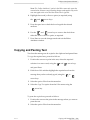
Copying and Pasting Text
Text from the message can be copied to the clipboard and pasted later.
To copy the required text, proceed as follows:
1 Position the cursor at a point in the text, where the required
selection is to start or end, using the
and
arrow keys,
and press Enter.
2 Hold down Ctrl and then highlight the required text from the
message that you have already typed, using the
or
arrow keys.
3 Select the option Editor from the menu bar.
4 Select the Copy Text option from the Editor menu using the
arrow key.
To paste the copied text, proceed as follows:
1 Position the cursor at the point in the message where you want to
paste the text.
2 Select the option Editor from the menu bar.
Rev AC
Copying and Pasting Text
5-9
Videojet 1310 Operator Manual
3 Select the Paste Text option from the Editor menu using the
arrow key.
This enables the copied text to be pasted at the required position.
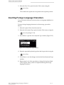
Inserting Foreign Language Characters
You can include characters from more than one language alphabet in a
message.
To insert foreign language characters in the message, proceed as
follows:
1 Select the option Editor from the menu bar.
2 Select the Set Keyboard Type option from the Editor menu, using the
arrow key (Figure 5-12).
3 Press Enter to open the Select Keyboard Type window (Figure 5-12).
Figure 5-12: Set Keyboard Type Window
4 Select the required keyboard type from the list provided, using the
arrow key.
5
Press Enter to save the changes and exit the Select Keyboard Type
window.
6 Repeat steps 1 to 4 of the procedure to change the keyboard back
to the original, when you have completed entering the foreign
language characters.
5-10
Inserting Foreign Language Characters
Rev AC
Videojet 1310 Operator Manual
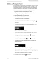
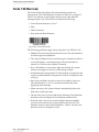
Inserting a Barcode
To insert a barcode into a message, proceed as follows:
Note: Refer Appendix B, “Supported Barcodes” for detailed information on
each type of supported barcode.
1 Select the option Messages from the menu bar (refer “Menu Bar”
on page 4-3 for instructions).
2 Select the New Message option using the
arrow key.
3 Press Enter to open the New Message window.
4 Type a name for the new message using the keypad.
Note: The message name may contain up to 30 alphanumeric characters,
including spaces.
5 Press Enter to open the Message Editor window.
6 Press F1 until the desired font size for the barcode is displayed.
Note: Barcodes less than 16 high do not support the addition of a human
readable version of the code.
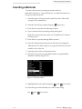
7 Select the option Editor, from the menu bar.
8 Select Inline Attributes from the Editor menu to open the Editor
Attributes window (Figure 5-13).
Figure 5-13: Barcode Option
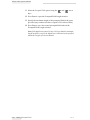
9 Highlight the Barcode option using the
and
arrow keys.
10 Select the type of barcode that you wish to insert, using
the
Rev AC
and
arrow keys.
Inserting a Barcode
5-11
Videojet 1310 Operator Manual
11 Select the Check sum option using the
and
arrow keys
and then press the spacebar to check the corresponding box, if you
want the barcode to include a check sum for error correction.
Note: If you cannot highlight “Check sum” at this point, the current
setting is mandatory for the selected bar code type.
12 Select the Human Readable option using the
and
arrow
keys and then select the relative position of the human readable
text (none or below) using the
and
arrow keys, if you
want a human readable version of the barcode text to appear near
the barcode.
Note: If you cannot highlight “Human Readable” at this point, the
current setting is mandatory for the selected bar code type and font size.
13 Press Enter to save the barcode and exit the Editor Attributes
window.
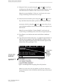
14 Type the barcode data at the cursor. A graphical representation of
the barcode now appears in the Message Editor window, along
with some helpful information about the allowable input for the
selected bar code type (Figure 5-14).
Approximation
of actual
barcode
appears in
message as
you type
Information about
allowable input
appears here
Typed barcode data
appears here
Figure 5-14: Message Editor Displaying Barcode Information
Note: You can also insert any pre-defined user field into a barcode as
long as all characters in the user field are valid for the type of barcode you
are creating.
5-12
Inserting a Barcode
Rev AC
Videojet 1310 Operator Manual
15 Move the cursor away when you have finished editing the
barcode, using
or
arrow key.
Note: When you save a message containing one or more barcodes, the
system attempts to verify the validity of each barcode, displaying an error
if any problems are found.
This enables the insertion of the required barcode in the print
message.
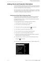
Working with User Fields
User fields are message inserts such as counters, time/date stamps,
text and prompted fields, shift codes, graphics, and logos. There are
several pre-defined user fields as well as custom user fields.
Inserting a Pre-defined User Field
To insert a pre-defined user field, proceed as follows:
1 Select the option Messages from the menu bar.
2 Press Enter to open the Messages menu.
3 Select the New Message option using the
arrow key.
4 Press Enter to open the New Message window.
5 Type a name for the new message using the keypad.
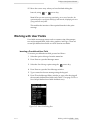
6 Press F2 in the Message Editor window to open a list showing all
the currently-defined user fields (refer Table 5-2 on page 5-15 for a
list of all pre-defined user fields and their uses).
Figure 5-15: User Field Dialog Box
Rev AC
Working with User Fields
5-13
Videojet 1310 Operator Manual
Note: In addition to any user fields that have been created by operators
and other technicians, the list normally contains a number of user fields
that are pre-defined.
7 Highlight the name of the user field you want to insert, using
the
and
arrow keys.
8 Press Enter to save the required type of user field and exit the
dialog box.
This enables the insertion of the selected user field in the print
message.
5-14
Working with User Fields
Rev AC
Videojet 1310 Operator Manual
Pre-defined User Fields
Field Name
Description
Typical Output
Alpha Month
The first three letters in the name
of the month in which the
message is printed
APR
Date
The date on which the message
is printed in Day/Month/Year
format
06/11/04
Date - YYYY
Same as Date, but showing a 4digit year
06/11/2004
Day of Week
The day of the week (numerical).
Note that you can select which
day of the week is designated as
day 1 (refer “Setting the Time and
Date - Gregorian Calendar” on
page 4-9)
5
Expiry Date
Print date along with a selected
number of days (refer
“Configuring the Date Offset for
Expiration Dates” on page 5-21)
07/12/04
Expiry Date - YYYY
Same as Expiry Date, but
showing a 4-digit year
07/12/2004
Julian Date
The day of the year (1-365*).
*366 days in the case of a Leap
Year
152
Shift
The printer replaces the value
here with a shift code at print
time. Set up the shifts in the
printer to be able to use this field
(refer “Setting Up Shifts” on
page 4-11)
B
Time
The time of day that the message
is printed (in hours, minutes and
seconds)
09:06:28
Week of Year
The week of the year on which
the message was printed. Note
that although week 1 begins with
the first day of the year, week 2
and all the following weeks begin
with the rollover day (refer
“Setting the Time and Date Gregorian Calendar” on
page 4-9)
36
Table 5-2: List of Commonly Used User Fields
Rev AC
Working with User Fields
5-15
Videojet 1310 Operator Manual
Creating a Custom User Field
To create a custom user field, proceed as follows:
1 Select the option User Field from the menu bar.
2 Press Enter to open the User Fields menu (Figure 5-16).
Figure 5-16: New User Field Option
3 Select the New User Field option using the
arrow key.
4 Press Enter to open the New User Field window (Figure 5-17).
Figure 5-17: New User Field Window
5 Type a name for the New User Field in the Name option provided.
6 Highlight the Description option on the same window using the
arrow key.
7 Select from the three types of user fields using the
and
arrow keys (refer Table 5-3 on page 5-17 for a description on
the type of user fields).
8 Press Enter to open the configuration dialog box (Figure 5-18) for
the type of user field selected.
Figure 5-18: Text Field Configuration Dialog Box
9 Enter the appropriate data in the Text field.
10 Press Enter to save the created user field and exit the configuration
dialog box.
5-16
Working with User Fields
Rev AC
Videojet 1310 Operator Manual
11 Press F2 at the message editor window to open the new user field
which is now included in the list of pre-defined user fields.
Types of User Fields
Description
Purpose
Text
This type of user field can hold a maximum of 50
characters and can be used for three different purposes:
• to create a named field containing normal text (as
in this example)
• to add a prompted field (refer “Adding a Prompted
Field” on page 5-19)
• to add time and date information (refer “Adding
Clock and Calendar Information” on page 5-21)
Counter
This type of field is used to add a numerical,
alphabetic or alphanumeric counter (refer “Adding
Counters” on page 5-25).
Logo
This type of field is used to insert logos and other
graphics (refer “Adding Logos and Other Graphics”
on page 5-27).
Table 5-3: Types of User Fields
Editing a User Field
The content and format of any existing user field can be altered.
To edit a user field, proceed as follows:
1 Select the option User Fields from the menu bar.
2 Press Enter to open the User Fields menu.
3 Select the Edit User Field option from the User Field menu using
the
arrow key.
4 Press Enter to open a list of all currently-defined user fields.
5 Select the field that you want to edit using the
arrow key,
and press Enter.
6 Edit the parameters according to your requirement.
7 Press Enter to save and exit the edited user field.
Note: You can edit a user field that is used in the message currently
being printed, without interrupting printing. Saving your changes
instructs the printer to begin printing the altered version of the user field.
However, the printer waits for the next product detected, to actually
make the change.
Rev AC
Working with User Fields
5-17
Videojet 1310 Operator Manual
Deleting a User Field
To delete a user field, proceed as follows:
1 Select the option User Fields from the menu bar.
2 Press Enter to open the User Fields menu.
3 Select the Delete User Field option from the User Field menu using
the
arrow key.
4 Press Enter to open a list of all currently-defined user fields.
5 Select the field that you want to delete using the
arrow key.
6 Press Enter to delete the selected user field and return to the Menu
screen.
Note: You can delete a user field that is part of the message currently being
printed, without interrupting printing. The printer continues to print the
message after removing the deleted user field.
Caution
DATA LOSS. The Delete User Field option does not ask for
confirmation to delete a User Field.
5-18
Working with User Fields
Rev AC
Videojet 1310 Operator Manual
Adding a Prompted Field
Prompted fields are used to define content that may change each time
the message is used. This may include a message of the day or other
content that is specific to a specific run of the product, but remains
constant for the entire run. The operator is prompted to provide the
field’s contents each time one of the following events occurs:
• A message containing a prompted field is loaded.
• The printer is put in print mode and the currently selected
message contains a prompted field in it.
To add a prompted field, proceed as follows:
1 Select the option User Fields from the menu bar.
2 Press Enter to open the User Fields menu.
3 Select New User Field from the User Fields menu using the
arrow key.
4 Press Enter to open the New User Field window (Figure 5-19).
Figure 5-19: New User Field Window
5 Type a name for the new prompted field in the space provided.
6 Highlight the Description option using the
arrow key.
7 Select the Text option using the
arrow keys.
and
8 Press Enter to open the configuration dialog box for text user
fields (Figure 5-20).
Figure 5-20: Prompted Field Configuration Dialog Box
9 Type a default value for the prompted field corresponding to the
field labeled Text. This text is displayed in the prompted field until
the operator is prompted for the text to replace it.
10 Highlight Attribute using the
Rev AC
arrow key.
Adding a Prompted Field
5-19
Videojet 1310 Operator Manual
11 Select the Prompted Field option using the
and
arrow
keys.
12 Press Enter to open the Prompted Field Length window.
13 Specify the maximum length of the prompted field in the space
provided (any number less than or equal to 50 is allowed here).
14 Press Enter to save the created prompted field and exit the
Prompted Field Length window.
Note: If the default text entered in step 9 is longer than the maximum
length specified in step 13, the default text is truncated to the specified
maximum. Lengths of 0 are not allowed.
5-20
Adding a Prompted Field
Rev AC
Videojet 1310 Operator Manual
Adding Clock and Calendar Information
Clock and calendar information can be added to a message in the form
of one or more placeholder variables that are automatically updated to
show the actual date and/or time of printing.
The same method can be used to add an expiration date to a message.
The expiration date is derived by adding a fixed number of days to the
actual date on which the message was printed.
Configuring the Date Offset for Expiration Dates
If you intend to add an expiration date to the message, information
regarding how many days ahead are required to be added to the
message print date in order to construct an expiration date, must be
entered into the printer first.
To set the expiration date in a message, proceed as follows:
1 Select the option Messages from the menu bar.
2 Press Enter to open the Messages menu.
3 Select the New Message option using the
arrow key.
4 Press Enter to open the New Message window.
5 Type a name for the new message using the keypad.
6 Press Enter to open the Message Editor window.
7 Hold down the Alt Key and press M in the keypad, to open the
Messages window from the menu bar.
8 Select the Message Parameters option from the Messages menu,
using the
arrow key.
9 Press Enter to open the Message Parameters window (Figure 5-21).
Figure 5-21: Message Parameters Window
Rev AC
Adding Clock and Calendar Information
5-21
Videojet 1310 Operator Manual
10 Select the Expiry (days ahead) option using the
and
arrow keys.
Note: This field is based on the Gregorian calendar used by western
nations. If you intend to include expiration dates based on the Arab Hejra
calendar, configure the Hej Exp field as well.
11 Increase or decrease the number of days displayed, using
the
or
arrow keys or type the desired number of days
(up to a maximum of 32,000).
12 Press Enter to save the settings and exit the Message Parameters
window.
Inserting Pre-configured Time and Date Inserts
The easiest way to insert a time stamp or a date stamp is to select one
that has already been configured. The interface of a new printer
contains several pre-configured inserts (called “user fields”), most of
which contain time and date information.
Refer “Inserting a Pre-defined User Field” on page 5-13 for a
description of all pre-configured user fields that are present in the
interface of a new printer.
Creating Custom Time and Date Inserts
Times and dates are inserted in messages by formatting a block of text,
which is known as “clock information.”
To create a clock information user field, proceed as follows:
1 Select the option User Fields from the menu bar.
2 Press Enter to open the User Fields menu.
3 Select the New User Field option from the User Fields Menu, using
the
arrow key.
4 Press Enter to open the New User Field window (Figure 5-22).
Figure 5-22: New User Field Window
5-22
Adding Clock and Calendar Information
Rev AC
Videojet 1310 Operator Manual
5 Type a name for the new time and date insert in the space
provided.
6 Highlight the Description field using the
7 Select the Text option using the
and
arrow key.
arrow keys, and
press Enter to open the configuration dialog box for Text user
fields (Figure 5-23).
Figure 5-23: Time Insert Dialog Box
8 Type the appropriate code in the field labeled Text, as required
(refer to Table 5-5 on page 5-24).
Note: Remember the following when entering the codes:
Codes are case-sensitive.
Although the table groups digits together for clarity, each letter actually
corresponds to a single digit. For example, “C” represents the last digit of
the year number.
The standard date codes are derived from the Gregorian calendar used by
western nations. The Arab Hejra calendar uses alternate date codes.
You can practically add any other character for formatting, including
numbers, spaces, punctuation marks, etc.
9 Press Enter after entering the codes, to save the settings and exit
the Time Insert dialog box.
The new insert appears in the list of defined user fields. Press F2 in
the Message Editor window. You can select the new field for
insertion in the message currently being edited.
Rev AC
Adding Clock and Calendar Information
5-23
Videojet 1310 Operator Manual
Examples
Desired output
Codes and Formatting
May 29, 2003 (print date)
NOP FG, 20BC (or NOP FG, hiBC)
10/29/03 (expiration date)
de/fg/bc
10:29
HI:JK
Table 5-4: Examples of Codes for Custom Time and Date Inserts
Time and Date Codes
Code
Definition
A
Numerical day of the week (1 to 7)
BC
Two-digit year
DE
Month (numerical)
FG
Day of the month
HI
Hours
JK
Minutes
LM
Seconds
NOP
Alpha month
QRS
Day of the year
TU
North American week number
VW
European week number
XY
First two digits of the four-digit expiration year
Za
First two digits of the current Hejra year
bc
Two-digit expiration year
de
Expiration month (numerical)
fg
Expiration day of the month
hi
First two digits of four-digit current year
nop
Alpha expiration month
jk
Last two digits of Hejra year
lm
Hejra month (numerical)
qr
Hejra day of the month
stuv
Hejra expiration year
wx
Hejra expiration month (numerical)
yz
Hejra expiration day of the month
Table 5-5: Time and Date Codes
5-24
Adding Clock and Calendar Information
Rev AC
Videojet 1310 Operator Manual
Adding Counters
Counters (also called “serializers”) are fields that change their value by
a fixed amount, each time a specified event occurs. For example, they
may be used to print a unique serial number on each product that
passes the production line.
To add a new counter, proceed as follows:
1 Select the option User Fields from the menu bar.
2 Press Enter to open the User Fields menu.
3 Select the New User Field option using the
arrow key.
4 Press Enter to open the New User Field window (Figure 5-24).
Figure 5-24: New User Field Window
5 Type a name for the new counter in the space provided.
6 Highlight the Description field using the
7 Select the Counter option using the
arrow key.
and
arrow keys.
8 Press Enter to open the configuration dialog box for counters
(Figure 5-25).
Figure 5-25: Counter Configuration Dialog Box
9 Set the values for all the fields in the counter configuration dialog
box (refer Table 5-6 on page 5-26 for definitions of various counter
fields).
Note: The Start Value, Current Value, and End Value fields must
contain the same number of characters. For example, if the new counter
Rev AC
Adding Counters
5-25
Videojet 1310 Operator Manual
counts from 1 to 500, be sure to enter “001” rather than “1” in the Start
Value and Current Value fields.
Counters may be numerical, alphabetic or alphanumeric. The system
automatically selects the type of counter based on the start, current and
end values configured. Alphanumeric counters count 0 to 9 and then A
to Z.
10 Press Enter to save the settings and exit the Counter Configuration
dialog box.
Counter Field Definitions
Field Name
Definition
Start Value
Value from which the count starts. The counter
returns to this value when it is reset.
Current Value
The counters current value. This field is primarily
used to change the current value of a counter that is
already in use. When setting up a new counter, the
value entered here should be identical to the Start
Value.
End Value
Value that the counter reaches at the end of the
count. The counter resets to the start value the next
time it is incremented.
Step Size
Number by which the counter is incremented or
decremented. This is a numerical value even for
alphabetic counters (a value of 2 causes an
alphabetic counter to count “a, c, e, g” etc.)
Step Direction
Set to Increment (count up) or Decrement (count
down)
Repeat Count
Specifies how many times the event selected in the
Inc/Dec on field must occur to cause the counter to
increment or decrement itself.
Leading Character
Leading zeros can be replaced with a different
character (for example a blank space). The default
setting is “0” which leaves leading zeros
unchanged.
Inc/Dec on
This field specifies what causes the counter to
increment or decrement itself.
Select PRINT to specify that the counter is
incremented or decremented each time a message
that contains the counter is printed.
Select the name of another counter to specify that
the counter is incremented or decremented when
the selected counter reaches its End Value.
Table 5-6: Definitions of Counter Fields
5-26
Adding Counters
Rev AC
Videojet 1310 Operator Manual
Adding Logos and Other Graphics
Graphics can be inserted by creating a user field of the logo type.
To add a new graphic to a message, proceed as follows:
1 Select the option User Fields from the menu bar.
2 Press Enter to open the User Fields menu.
3 Select the New User Field option using the
arrow key.
4 Press Enter to open the New User Field window (Figure 5-26).
Figure 5-26: New User Field Window
5 Type a name for the new graphic in the space provided.
6 Highlight the Description field using the
7 Select the Logo option using the
and
arrow key.
arrow keys.
8 Press Enter to open the Logo Editor for logos and other graphics
(Figure 5-27).
Figure 5-27: Logo Editor for Construction of Logos
9 Create the graphic by controlling the cursor position using a
combinations of keys from the keypad (refer Table 5-7 on
page 5-28 for the key combinations and their functions).
Rev AC
Adding Logos and Other Graphics
5-27
Videojet 1310 Operator Manual
Key Combination
Cursor Movement
Move the cursor one dot
at a time without drawing
a line.
or
+
alt
Move the cursor ten dots
at a time without drawing
a line.
or
Space Bar
+
shift
ctrl
Draw a single dot at the
current cursor position.
+
or
or
Move the cursor one dot
at a time and draw a
line.
Move the cursor one dot
at a time and delete any
dots drawn.
Table 5-7: Key Combinations Used for the Construction of Graphics
Note: Content is added to a graphic by any of the following procedures:
Text can be typed by using the Set Cursor option in the Editor menu. The
font size for the typed text can be set using the F1 key or the Select Font
option in the Editor menu.
Foreign language characters can be inserted by selecting Set Keyboard
Type from the Editor menu and then typing the desired characters.
User fields such as counters, time stamps or another graphics can be
embedded. Press F2 or select Insert User Field from the Editor menu to
do so.
Graphic editing tasks can be achieved by the function of Copy and Paste
blocks. Refer “Block Editing Functions” on page 5-29 for more
information.
10 Crop the graphic to the desired size by cutting out the extra space
at the edges (refer “Cropping a Graphic” on page 5-33 for
instructions).
11 Hold down Shift and Press F1 to save your graphic and exit the
Logo Editor window, when your logo is complete.
Changing Logo Size
After inserting the logo, the size can be changed. To change the height
and width of the logo, proceed as follows:
1 Select the option Editor from the menu bar.
5-28
Adding Logos and Other Graphics
Rev AC
Videojet 1310 Operator Manual
2 Press Enter to open the Editor menu.
3 Highlight the Set Logo Size option using the
arrow key and
press Enter to open the Logo Editor box.
Figure 5-28: Set Logo Size Option
4 Change the height of the logo to the required size, using the
and
arrow keys.
5 Change the width of the logo to the required size, using the
and
arrow keys.
This enables changing the size of the logo created.
Block Editing Functions
Selecting a rectangular area of the graphic called as the “block”, within
the logo editor allows you to delete the block or make a copy of it.
To select a block after the creation of a logo or graphic, proceed as
follows:
1 Hold down Alt and press E to open the Editor menu in the Logo
Editor window.
2 Select the Set Block option using the
Rev AC
arrow key (Figure 5-29).
Adding Logos and Other Graphics
5-29
Videojet 1310 Operator Manual
Figure 5-29: Logo Editor Menu
3 Press Enter to see a rectangle appear in the Logo Editor, which
indicates the outline of the block to be selected (Figure 5-30).
Resize this
rectangle
to define
the size of
the desired
block
Figure 5-30: Block Editing Function
5-30
Adding Logos and Other Graphics
Rev AC
Videojet 1310 Operator Manual
4 Position and resize the outline rectangle using a series of key
combinations on the keypad (refer Table 5-8 on page 5-31 for the
various key combinations).
Key combination
+
ctrl
Function
Move the right-hand edge.
or
shift
+
or
shift
+
or
+
ctrl
,
alt
or
,
+
or
or
Move the left-hand edge
Move the top edge.
Move the bottom edge.
Move the whole outline by one
dot at a time.
Move the whole outline by ten
dots at a time.
Table 5-8: Key Combinations for Block Editing Function
5 Press Enter when you have completed positioning and resizing
the block’s outline.
Note: The outline rectangle disappears at this point.
This enables selecting a block, following the creation of a logo or
graphic.
Deleting a Selected Block
To clear the contents of a selected block, proceed as follows:
1 Hold down Alt and press E to open the Editor menu in the Logo
Editor window.
2 Select the Set Block option using the
arrow key.
3 Press Enter to see the selected block appear in the window.
4 Hold down Alt and press E to open the Editor menu in the Logo
Editor window.
5 Select the Delete Block option using the
arrow key.
6 Press Enter to clear the contents in the selected block.
Rev AC
Adding Logos and Other Graphics
5-31
Videojet 1310 Operator Manual
Copying and Pasting a Selected Block
To copy and paste a selected block, proceed as follows:
1 Hold down Alt and press E to open the Editor menu in the Logo
Editor window.
2 Select the Set Block option using the
arrow key.
3 Press Enter to see the selected block appear in the window.
4 Hold down Alt and press E to open the Editor menu in the Logo
Editor window.
5 Select the Copy Block option using the
arrow key, and press
Enter (Figure 5-31).
Figure 5-31: Copy Block Option
6 Move the cursor to the desired location where you want to paste
the contents of the selected block (the upper left hand corner of the
graphic is pasted at the cursor location).
7 Hold down Alt and press E to open the Editor menu in the Logo
Editor window.
8 Select the Paste Block option using the
arrow key.
9 Press Enter to paste the contents of the selected block in the
desired location, on the Logo Editor screen.
5-32
Adding Logos and Other Graphics
Rev AC
Videojet 1310 Operator Manual
Cropping a Graphic
Cropping is the process of trimming the edges of a graphic to
eliminate the empty space that surrounds it.
To crop a graphic, proceed as follows:
1 Hold down Alt and press E to open the Editor menu in the Logo
Editor window.
2 Select the Set Logo Size option using the
arrow key (Figure 5-
32).
Figure 5-32: Set Logo Size Option
3 Press Enter to see the appearance of a frame depicting the current
boundaries of the graphic (Figure 5-33).
Frame
indicates the
current
borders of the
graphic
Figure 5-33: Graphic Cropping Function
4 Adjust the size of the frame using a combination of controls, until
boundaries of the graphic are as required (refer Table 5-9 on
page 5-34 for the controls used and their functions).
Rev AC
Adding Logos and Other Graphics
5-33
Videojet 1310 Operator Manual
Key combination
,
alt
,
+
Function
Adjust the frame
size one dot at a
time.
or
,
,
or
Adjust the frame
size ten dots at a
time.
Table 5-9: Key Combinations for Graphic Cropping Function
5 Press Shift+F1 to save the settings.
Configuring Message Parameters
Message parameters include variables that affect the appearance and
behavior of the entire message. You can change the parameters for a
specific message or the default parameters for all messages.
To edit message parameters, proceed as follows:
1 Select the option Messages from the menu bar.
2 Select Message Parameters in the Messages menu using the
arrow key, if you want to set parameters for the current message.
If you want to set the parameters for all messages, select Default
Parameters.
3 Press Enter to open the Message Parameters dialog box (Figure 534).
Note: Changes made to the default settings affects subsequent new
messages created, but does not affect existing messages.
Figure 5-34: Message Parameters Dialog Box
5-34
Configuring Message Parameters
Rev AC
Videojet 1310 Operator Manual
4 Select each parameter to be edited using the
arrow key and
enter the required value.
5 Press Enter to save settings and exit the Message Parameters
dialog box (refer Table 5-10 for a description of all the message
parameters).
Parameter
Range
Description
Expiry
(days ahead)
0 to 32000
days
Sets an expiry date the selected number of
days after the print date. This parameter
affects the expiration dates based on the
Gregorian calendar used by western nations
(refer “Adding Clock and Calendar
Information” on page 5-21 for more
information).
Hej Expiry
(days ahead)
0 to 32000
days
Sets an expiry date the selected number of
days after the print date. This parameter
affects the expiration dates based on Arab
Hejra calendar (refer “Adding Clock and
Calendar Information” on page 5-21 for more
information).
Width
1 to 255
Sets the message width. The minimum width
is limited by the maximum print speed. Set
the width to 1 to print at the maximum
achievable rate for the selected number of
“printed drops”. Each increment in width
increases the message width by
approximately 3 %.
Character
Height
1 to 10
Adjusts the vertical dot spacing of the entire
message by selecting one of ten preset
values. Typically, these values would have
been configured so that 1 generates the
shortest message and 10 generates the
tallest message.
Character
Gap
0 to 10
Sets the character gap between 0 (equivalent
to a single vertical line of dots) to 10 rasters
width (equivalent to 11 vertical lines of dots).
Due to character formation, setting 0 gives a
character gap of 1 raster.
This setting does not affect the spacing of
printed barcodes.
Table 5-10: Description of Message Parameters
Rev AC
Configuring Message Parameters
5-35
Videojet 1310 Operator Manual
Parameter
Range
Description
Product
Delay
0 to 10000
Sets the product delay (the time between the
start of product (trigger point) and the print
start position).
Reverse
On/Off
Toggle reversed character (back to front)
printing.
Invert
On/Off
Toggle inverted character (upside down)
printing.
Raster
Repeat
1 to 10
Sets the number of times the same raster is
printed. This allows characters to be emboldened.
High Speed
Print
On/Off
Setting High Speed Print Off instructs the
printer to maintain high print quality even if it
has to print more slowly to do so. This setting
affects the print quality. Setting High Speed
Print On can affect the print quality but allows
full speed printing. Refer to the Print
Specification Table in the Service Manual for
font specific details.
Table 5-10: Description of Message Parameters
Note: Product delay and message length are dependent on the line speed and
resolution of the shaft encoder.
5-36
Configuring Message Parameters
Rev AC
Videojet 1310 Operator Manual
Copying Messages
If only minor changes are required to be made to an existing message
to create a new one, use the Copy Message option.
To copy a message, proceed as follows:
1 Select the option Messages from the menu bar.
2 Select the Copy Message option using the
arrow key.
3 Press Enter to open the Copy Message dialog box (Figure 5-35).
Figure 5-35: Copy Message Dialog Box
4 Enter the name of the message from which you want to copy, in
the From field, or press F2 to select from a list of available
messages.
5 Select the To field using the
arrow key and enter the name of
the message where you want to paste the message copied in Step
4.
6 Press Enter to save the copied message and return to the Menu
screen.
Deleting Messages
You can delete either a single message or all messages (except the Test
Message, which cannot be deleted).
Deleting a Single Message
1 Select the option Messages from the menu bar.
2 Select the Delete Message option using the
arrow key, to
delete a single message.
Rev AC
Copying Messages
5-37
Videojet 1310 Operator Manual
3 Press Enter to open the Select Message dialog box (Figure 5-36).
Figure 5-36: Select Message Dialog Box
4 Highlight the message name using the
and
arrow keys,
or enter the name of the message using the keypad.
5 Press Enter to delete the message and return to the Menu screen.
Caution
DATA LOSS. Ensure the correct message name is selected for
message deletion as a message selection confirmation prompt is
not given.
Deleting all Messages
To delete all messages, proceed as follows:
1 Select the option Messages from the menu bar.
2 Select the Delete All Messages option using the
arrow key.
3 Press Enter to delete all the messages and return to the Menu
screen.
Caution
DATA LOSS. With the above operations, all messages apart from
the Test Message and the message currently loaded in the editor
are deleted.
5-38
Deleting Messages
Rev AC
Videojet 1310 Operator Manual
Checking Free Message Space
The printer stores all the messages created on a flash memory “disk.”
The high capacity of this disk makes it unlikely that the printer runs
out of space to store messages.
However, you can check the amount of free message space left in the
printer by doing the following:
1 Select the option Messages from the menu bar.
2 Select the Show Free Message Space option using the
arrow
key.
3 Press Enter to open the Memory Space dialog box (Figure 5-37).
Refer Table 5-11 for the description of the fields appearing in the
window.
Figure 5-37: Memory Space Dialog Box
Field
Meaning
Free Disk Space
The total amount of memory (in bytes) that
remains available for creating new messages.
Message Count
Shows the total number of messages currently
stored in the printer’s memory.
Table 5-11: Description of Fields in the Memory Space Window
Note: When the free disk space approaches zero, it becomes impossible to
create new messages. However, you can make space available by deleting
unused messages.
4 Press Enter to close the dialog box and return to the Menu screen.
Rev AC
Checking Free Message Space
5-39
Loading and Printing a
Job
6
This chapter contains the following topics:
• Loading an existing message
• Starting the printing process
• Stopping the printing process
• Monitoring the printing process
• Resetting serializers
• Resetting the product counters
Loading an Existing Message
The message that is currently printing appears in the box, at the
bottom of the main screen.
To select a different message to print, proceed as follows:
1 Press F2 to display the Select Message menu (Figure 6-1).
Figure 6-1: Select Message Menu
2 Highlight the name of the desired message using the
and
arrow keys.
Rev AC
Loading an Existing Message
6-1
Videojet 1310 Operator Manual
Note: To highlight the name of the message required, type the first letter of
the message. The highlight moves to the beginning of the message whose
name begins with that letter.
3 Press Enter to select the highlighted message for the printing process.
Starting the Printing Process
To print the message selected currently, press F1.
Wait for the printer to complete the jet start sequence (up to five minutes).
Printing commences automatically once the sequence is completed.
Caution
EQUIPMENT DAMAGE. Make-up solvent is used to clean the
printhead during the start and stop cycles. Therefore, starting and
stopping the printer repeatedly over a short period of time can dilute
the ink.
Stopping the Printing Process
To stop the ink jet and cease the printing, press F1.
Wait for the printer to complete the jet stop sequence. The green LED and
the ink jet icon stops flashing (up to 3 minutes). Following this, the
printing process ceases.
Caution
EQUIPMENT DAMAGE. Do not disconnect the printer until the jet
stop sequence has been completed.
6-2
Starting the Printing Process
Rev AC
Videojet 1310 Operator Manual
Monitoring the Printing Process
The three keypad LEDs and the lights on the optional lamp stack
shows the printer status at its simplest level (Figure 6-2).
LEDs
Figure 6-2: Printer Keypad
Red
This indicates that there is a fault condition that prevents printing. An
icon appears on the screen along with a corresponding error message.
Refer “Printer Status Icons” on page 9-4 and “Fault and Warning
Messages” on page 9-8 for more information on troubleshooting.
Amber
This indicates a condition which may require user intervention, but
does not usually prevent printing. This includes conditions that may
or may not be considered a problem for the current application (such
as slight print distortions). It also includes potential problems that are
not affecting printing yet, but eventually might (such as low ink
supply). Refer “Troubleshooting the Amber LED” on page 9-2 for
more information.
Green
This indicates that the printer is able to print correctly. The Green LED
(but not the lamp) flashes when the printhead is starting up or
shutting down and when print has been disabled.
Rev AC
Monitoring the Printing Process
6-3
Videojet 1310 Operator Manual
Resetting Message Counters
Message counters (also called “serializers”) are user-defined counters
that are inserted in messages. Such a counter is typically incremented
whenever the message is successfully printed.
Refer “Adding Counters” on page 5-25 for information on creating
message counters.
To reset any message counter to its starting value, proceed as follows:
1 Select the option User Fields from the menu bar.
2 Select the Reset Counter option from the User Fields menu, using
the
arrow key.
3 Press Enter to open the Select Counter to Reset menu (Figure 6-3).
Figure 6-3: Select Counter to Reset Menu
4 Select the counter that you want to reset.
5 Press Enter to reset the required counter and exit the Select
Counter to Reset menu.
6-4
Resetting Message Counters
Rev AC
Videojet 1310 Operator Manual
Resetting the Product Counter
The product counter (Figure 6-4 on page 6-5) shows the total number
of products that the printer has detected. All detected products are
counted here including the products on which the printer has not
printed a message.
Product
Counter
Figure 6-4: Product Counter
To reset the product counter, proceed as follows:
1 Select the option Data Logging from the menu bar.
2 Select the Product Counter option from the Data Logging menu,
using the
arrow key.
3 Press Enter to open the Product Counter dialog box (Figure 6-5).
Figure 6-5: Product Counter Dialog Box
4 Set the Reset Counter field to “Yes” using the
and
arrow
keys.
5 Press Enter to reset the product counter and exit the Product
Counter dialog box.
Rev AC
Resetting the Product Counter
6-5
Videojet 1310 Operator Manual
Hiding the Product Counter
To hide the product counter, proceed as follows:
1 Select the option Data Logging from the menu bar.
2 Select the Product Counter option from the Data Logging menu
using the
arrow key.
3 Select Product Counter from the Data Logging menu.
4 Press Enter to open the Product Counter dialog box (Figure 6-6).
Figure 6-6: Product Counter Dialog Box
5 Highlight the Display It? field using the
6 Press the
and
arrow key.
to select “No.”
7 Press Enter to save the settings and exit the Product Counter
dialog box.
External Select Table and Message Select
You can set the messages stored in the machine to print from an
internal source (i.e. the keyboard) or an external source (another
machine on the product line).
To set the message, proceed as follows:
1 Select the Messages menu.
2 Select Message Select Source (Figure 6-7). The Message Select
Source dialog opens.
Figure 6-7: Message Select Source Screen
3 Use the arrow keys to highlight the required source - either
Internal or External.
6-6
Resetting the Product Counter
Rev AC
Videojet 1310 Operator Manual
4 Press ENTER to set the message select source and return to the
Menu screen.
5 If the external message select is desired, select the Messages menu
again.
6 Select Edit External Select Table (Figure 6-8). The External
Message Select dialog opens.
Figure 6-8: External Message Select Screen
7 Enter the name(s) of the message(s) at the location desired for the
external source.
8 Press the F2 key to select the message names from a list of those
available or enter the message names. Entering message names
not stored on this machine are ignored.
When you have assigned all the messages to the locations (range from
0 to 99) that you want to be available to the external source, press
ENTER to return to the Menu screen.
Rev AC
Resetting the Product Counter
6-7
7
Line Setup
This chapter contains the following topics:
• Triggering a print
• Compensating for changes in line speed
Triggering a Print
Once the ink jet is turned on, individual prints are triggered in one of
the following three ways, depending upon the configuration of the
printer:
• Printing manually
• Printing with a product detector
• Printing continuously
Printing Manually
This option manually triggers a single print of the message selected
currently. It is generally used only for troubleshooting purposes.
To manually trigger printing, proceed as follows:
1 Ensure that the printer is set up to receive shaft encoder pulses by
doing one of the following:
• Check if the shaft encoder is properly installed and configured
according to the instructions in “Compensating for Changes in
Line Speed” on page 7-6, and ensure that the line that the
encoder measures is moving.
• Set the Shaft Encoder Source setting to “Internal.”
2 Select Manual Print from the Print menu.
3 The printer then prints the currently loaded message.
Rev AC
Triggering a Print
7-1
Videojet 1310 Operator Manual
Printing with a Product Detector
Product detectors can be used to trigger message printing when a product
passes the printhead. This method enables automatic printing of one or
more messages on each product present on a moving line.
Installation
Installation and setup of a product detector varies depending upon the
model of product detector used (refer the installation instructions that
come along with your product detector). However, the following
overview is true for all product detector models.
To install a product detector, proceed as follows:
1 Mount the product detector in a position that enables it to detect the
product when it is in print position.
2 Shut down the printer normally.
3 Attach the product detector to the Print Trigger 1 port on the side of
the printer.
4 Start the printer.
5 Configure the printer’s operating software to use the product detector
(refer “Configuring the Product Detector Ports” on page 7-2).
Configuring the Product Detector Ports
To configure the product detector ports, proceed as follows:
1 Select the option Configure from the menu bar.
2 Select the Photocell Source option from the Configure menu using
the
arrow key.
3 Press Enter to open the Print Control dialog box (Figure 7-1).
Figure 7-1: Print Control Dialog Box
7-2
Triggering a Print
Rev AC
Videojet 1310 Operator Manual
4 Select the Photocell Levels option from the Configure menu using
the
arrow key.
5 Press Enter to open the Photocell Levels dialog box (Figure 7-2).
Figure 7-2: Photocell Levels Dialog Box
6 Select the “Active High” or “Active Low” options (NPN detectors
are Active high and PNP detectors are Active Low) using
the
and
arrow keys.
7 Press Enter to save the settings and exit the Photocell Levels dialog
box.
Print Acknowledge
This option is located in the Print Ack Control menu (Figure 7-3), and
sends a signal to an external control system.
Figure 7-3: Print Acknowledge
There are four possible control setting options available. Select these
control setting options using the
and
arrow keys.
1 After Compile: The Print ACK ASCII code is sent after the update
of any dynamic information such as Clock Codes or counter
information in the message to be printed.
2 After Print: The Print ACK ASCII code is sent after the message
has been printed.
3 Both: The Print ACK ASCII code is sent after the message has been
compiled and after it has been printed.
4 Off: Default setting. No print acknowledge sent.
Rev AC
Triggering a Print
7-3
Videojet 1310 Operator Manual
Print ACK ASCII Code
This option is also located in the Print Ack Control menu, and sets the
ASCII character code (0-255) to be sent to the external control system.
Set Language
This feature allows selection of language character sets. Specific
language selections changes the menu language.
To set specific languages, proceed as follows:
1 Select Set Language (Figure 7-4 on page 7-4) from the Configure
menu. This displays a list of languages to select depending upon
the version of software installed.
Figure 7-4: Select Language
2 Select the desired language and press ENTER.
Printing Continuously
The continuous printing option prints a message repeatedly at a
regular time or distance interval. This is particularly useful for
applications such as wire and cable marking, where the same message
is printed at regular intervals along the length of a single product. The
printer continues printing for as long as the product continues to be
detected.
To print continuously at regular intervals, proceed as follows:
1 Select the option Print from the menu bar.
2 Select the Continuous Print option from the Print menu, using the
arrow key.
3 Press Enter to open the Continuous Print dialog box (Figure 7-5).
7-4
Triggering a Print
Rev AC
Videojet 1310 Operator Manual
Figure 7-5: Continuous Print Dialog Box
4 Do one of the following:
• To configure continuous printing at a specific time interval,
proceed as follows:
a. Set the Continuous Mode field to the “Time Mode” option using
the
and
arrow keys.
b. Select the Time Mode Delay option using the
arrow key.
c. Enter the number of ticks of the internal 64 Hz clock between
each printed message (each tick takes roughly 15.6 ms), using
the
and
arrow keys.
d. Press Enter.
e. Generate a product detect signal to start printing. This can be
accomplished by either:
• Passing a product past the product detector (if installed)
• Creating an inactive to active transition on the product detect
input by using the Photocell Levels option from the
Configure Menu
• To configure continuous printing at a specific distance interval,
proceed as follows:
a. Ensure that a supported shaft encoder is properly installed and
configured. Refer “Compensating for Changes in Line Speed”
on page 7-6 for more information.
b. Set the Continuous Mode field to the “SE Mode” option using
the
and
arrow keys.
c. Set the Printing Distance value to the number of shaft encoder
pulses between the start of each printed message (Range: 1 to
10,000), using the
and
arrow keys.
d. Press Enter to start printing.
Rev AC
Triggering a Print
7-5
Videojet 1310 Operator Manual
Compensating for Changes in Line Speed
Messages are printed on a moving surface. Hence, a change in line
speed can cause the distortion of messages. For example, a faster line
speed may cause messages to appear wider because the dots are
actually landing further apart. Similarly, a slower line speed may
cause messages to appear narrower and a stopped line can reduce the
message to a single vertical column of ink.
Since this type of distortion is usually undesirable, the printer has the
capability to compensate for changes in the line speed. To do this,
however, the printer must be supplied with constant updates about
the current line speed. Typically, this information is provided by a
device called a “Shaft Encoder”.
Operating without a Shaft Encoder
When the printer is used on a line whose speed never changes, a shaft
encoder is not necessary. In this case, the printer may be configured to
use the “internal encoder” option. This option causes the printer to
separate the printing of each column of dots by a fixed time interval. If
the line moves at a constant rate, the dot columns appears evenly
spaced.
To operate a printer without a shaft encoder, proceed as follows:
1 Select the option Configure from the menu bar.
2 Select the Shaft Encoder Source option from the Configure menu
using the
arrow key.
3 Press Enter to open the Print Control dialog box (Figure 7-6).
Figure 7-6: Print Control Dialog Box
4 Select the Shaft Encoder Source option using the
7-6
Compensating for Changes in Line Speed
arrow key.
Rev AC
Videojet 1310 Operator Manual
5 Set the Shaft Encoder Source field to “Internal” using the
and
arrow keys.
6 Press Enter to save the settings and exit the Print Control dialog
box.
Note: The spacing between columns of dots can be adjusted using the
Width setting in the Message Parameters window. A width of “1” causes
the columns to be printed as close together as possible at the current line
speed. The space between columns is increased by approximately 3% for
each additional +1 to this value.
This printer can now be used without a shaft encoder.
Configuring the Printer to Use a Shaft Encoder
Installation and setup of a shaft encoder varies depending on the
model of shaft encoder used (refer the installation instructions that
come along with your shaft encoder). However, there are some aspects
of installation that are common to all shaft encoder models.
To install a shaft encoder, proceed as follows:
1 Mount the shaft encoder to a position that allows it to reflect the
speed of the product.
2 Shut down the printer normally.
3 Attach the shaft encoder to the shaft encoder port at the side of the
printer (the port is an optional item that may also need to be
installed).
4 Start the printer.
5 Configure the printer’s operating software to use the shaft encoder
(refer “Software Configuration” on page 7-7).
Software Configuration
To configure the printer to use a shaft encoder, proceed as follows:
1 Select the option Configure from the menu bar.
2 Select the Shaft Encoder Source option from the Configure menu
using the
arrow key.
3 Press Enter to open the Print Control dialog box (Figure 7-7).
Rev AC
Compensating for Changes in Line Speed
7-7
Videojet 1310 Operator Manual
Figure 7-7: Print Control Dialog Box
4 Select the Shaft Encoder Source option using the
arrow key.
5 Set the Shaft Encoder Source field to “External” using the
and
arrow keys.
6 Press Enter to save the settings and exit the Print Control dialog
box.
7-8
Compensating for Changes in Line Speed
Rev AC
8
Maintenance
This chapter contains the following topics:
• Conducting routine inspection and cleaning
• Replacing the ink and make-up bottles
• Scheduling service of the printer
• Viewing the run hour timers
• Taking backup of the printer configuration
Conducting Routine Inspection and Cleaning
The most frequently occurring maintenance processes include the
following:
• Visually inspecting the air and fluid tubes for leaks (refer
“Visually Inspecting the Printer” on page 8-1).
• Checking the printhead and cleaning it when required (refer
“Inspecting and Cleaning the Printhead” on page 8-2).
• Inspecting the fan filter for cleaning or replacement (refer
“Inspecting and Replacing the Fan Filter” on page 8-6).
The visual inspection should be done every time you open the ink
compartment or atleast once in a week.
The regularity with which the inspection and cleaning of the printhead
and fan filter are to be repeated, varies depending on the conditions in
which the printer is operating. When you install a new printer,
perform these tasks once a week. After a few weeks, the regularity
with which these tasks are to be performed can be determined as
required.
Visually Inspecting the Printer
Inspect the printer cabinet carefully. Open the fluids compartment and
visually inspect all fluid bearing components for leaks. Check for any
fluid accumulation (or build-up of dried fluids) at the bottom of the
ink compartment. If leaks or fluid accumulation is detected, contact a
Videojet-trained service technician immediately.
Rev AC
Conducting Routine Inspection and Cleaning
8-1
Videojet 1310 Operator Manual
Inspecting and Cleaning the Printhead
Printhead cleaning is required when the ink build-up is affecting the
printer operation. Since the system automatically cleans the nozzle and
ink return line with the make–up fluid each time you start up or shut
down the printer, the printhead remains clean for a long period of time.
Printhead Inspection
To inspect the printhead, proceed as follows:
1 If the printer is on, press the F1 key to begin the four minute printhead
shutdown sequence.
2 When the shutdown sequence is complete, disconnect the AC power
cable from the AC power.
Warning
PERSONAL INJURY. Before continuing, ensure that the AC power
is disconnected (unplugged). Failure to follow this warning may
result in personal injury.
3 Remove the screw that secures the front printhead cover using a
screwdriver.
4 Detach the front printhead cover and retain the screw (Figure 8-1 on
page 8-2).
Figure 8-1: Front Printhead Cover Removal
5 Visually inspect the printhead assembly for foreign particles and ink
that accumulates at the nozzle orifice (located at the front of the
nozzle), charge tunnel, high voltage assembly, and ink return block
8-2
Conducting Routine Inspection and Cleaning
Rev AC
Videojet 1310 Operator Manual
(refer Figure 8-2 for the location of each component of the
printhead).
1
2
3
4
1. Nozzle
2. High Voltage Assembly
3. Ink Return Block
4. Charge Tunnel Assembly
Figure 8-2: Printhead Component Identification
6 If ink build-up is found, proceed to “Printhead Cleaning” on
page 8-4.
7 If ink build-up is not found, cleaning is not required at present.
Replace the cover and secure it with the screw retained in step 4.
Rev AC
Conducting Routine Inspection and Cleaning
8-3
Videojet 1310 Operator Manual
Printhead Cleaning
To clean the printhead, proceed as follows:
1 Place the service tray (Item 3 in Figure 8-3) below the printhead
(Item 1) in order to collect the ink and make-up fluid.
2 Ground the tray by attaching one end of a ground wire (Item 2) to
the tray and the other end to the printhead faceplate.
Warning
PERSONAL INJURY. Failure to ground the service tray properly
when using flammable ink may cause fire due to static discharge.
1
2
3
1. Printhead
2. Ground wire
3. Service tray
Figure 8-3: Grounding the Service Tray to the Printhead
8-4
Conducting Routine Inspection and Cleaning
Rev AC
Videojet 1310 Operator Manual
Caution
EQUIPMENT DAMAGE. Be very careful while cleaning the
charge tunnel. Serious misalignment or damage may occur if
excessive force is used during cleaning.
3 Ensure that the printhead is pointing down to the grounded
service tray. Flush away the contaminants using the
recommended Videojet cleaning solution or make–up fluid
(Figure 8-4).
Note: Use cleaning solution sparingly. Do not flush excessive amounts
of cleaning solution into the ink return block.
Figure 8-4: Cleaning the Printhead
4 Dry the printhead completely using either compressed air at
approximately 20 psi (1.4 bar) or air flow produced by squeezing
the blow bulb (P/N 21000170).
Caution
EQUIPMENT DAMAGE. Air dry only. Do not use shop cloth or
paper towels to dry the printhead or the cover. These items can
deposit particulate contaminants in the printhead.
Do not force compressed air into the ink return block.
5 Disconnect the ground wire from the printhead and the service
tray.
6 Clean the front printhead cover, if required.
Rev AC
Conducting Routine Inspection and Cleaning
8-5
Videojet 1310 Operator Manual
7 Attach the cover to the printhead and secure it with the cover
retaining screw.
8 Dispose the cleaning solution in the service tray.
Caution
EQUIPMENT DAMAGE. Do not pour the cleaning solution into
sinks, sewers, or drains. Comply with the appropriate
regulations when disposing the printer fluids. Consult the
appropriate regulatory agency for more information.
Inspecting and Replacing the Fan Filter
The fan filter may last for several months before a replacement is
required. However, in exceptionally dirty environments, it may need
to be replaced earlier. In case of a new printer, begin by inspecting the
filter once a week. After several weeks, you should be able to
determine an inspection schedule based on how quickly the filter
becomes dirty.
To inspect the fan filter, proceed as follows:
1 If the printer is on, press the F1 key to begin the four minute
printhead shutdown sequence.
2 When the shutdown sequence is complete, open the electronics
compartment door of the printer.
Warning
PERSONAL INJURY. Before continuing, ensure that the AC
power is disconnected (unplugged). Failure to follow this
warning may result in personal injury.
8-6
Conducting Routine Inspection and Cleaning
Rev AC
Videojet 1310 Operator Manual
3 Remove and retain the nut (Figure 8-5) that holds the fan assembly
in place, by turning it counter-clockwise.
Nut
Figure 8-5: Retaining Nut in the Fan Assembly
Rev AC
Conducting Routine Inspection and Cleaning
8-7
Videojet 1310 Operator Manual
4 Pull out the front of the fan assembly and remove the fan filter
(Figure 8-6).
Fan Filter
Figure 8-6: Fan Filter Removal
5 Inspect the fan filter. If the filter appears dirty, replace it with a
clean filter. If the filter is clean, refit the same filter.
6 Replace the fan assembly and secure it with the nut that was
retained in step 4.
Replacing the Ink and Make-Up Bottles
The ink and make-up bottles must be replaced when the printer
indicates that one of these fluids is low in supply.
When the ink is low, empty or full, the printer displays the icons
shown in Figure 8-7.
Ink Low
Ink Out
Ink Full
Figure 8-7: Ink Supply Icons
8-8
Replacing the Ink and Make-Up Bottles
Rev AC
Videojet 1310 Operator Manual
When the make-up fluid is low, empty or full, the printer displays the
icons shown in Figure 8-8.
Make-Up Low
Make-Up Out
Make-Up Full
Figure 8-8: Make-Up Fluid Supply Icons
What is “Make-Up?”
Fast-drying inks like the ones used in the Videojet 1310 printer
solidify quickly when exposed to air as well as when circulated
within the printer. To solve this problem, the printer occasionally
adds a thinning solution which is known as “Make-Up.”
Replacing the Bottle
Note: Whenever the Ink Full or Make-up Full icon appears in the display, do
not add a new bottle of fluid to the corresponding tank.
To replace the ink bottle or the make-up bottle, proceed as follows:
1 Open the ink compartment door of the printer (Figure 8-9).
Figure 8-9: Ink System Compartment
2 Rotate the engagement mechanism arm fully to the right on the
tank where the bottle is to be replaced.
Rev AC
Replacing the Ink and Make-Up Bottles
8-9
Videojet 1310 Operator Manual
3 Slide the empty bottle outwards.
4 To replace the make-up bottle, proceed to step 5.
5 Slide in a fresh bottle of fluid into the appropriate bracket in the
ink compartment.
Note: The shape of the make-up and ink bottles prevents them from being
inserted all the way into the wrong bracket (an ink bottle cannot be
inserted all the way into the make-up bracket or vice versa).
6 Once the bottle is completely inserted in the bracket, rotate the
engagement mechanism arm fully to the left to engage the bottle
to the tank.
Scheduling the Printer Service
The printer should be serviced by Videojet-trained service personnel
after every 5000 hours of printer operation. Usually, the “Service Due”
icon (Figure 8-10 on page 8-10) appears, to indicate the appropriate
time.
Figure 8-10: “Service due” Icon
However, if the printer has been in operation for more than 5000
hours, it is a good idea to schedule a service visit even if this icon does
not appear.
Viewing the Run Hour Timers
The printer maintains two resettable timers that track the length of
time it has been in operation. They comprise of:
• Pump Hours: This timer takes into account the total number of
hours that the main ink system pump has been running since the
last time the timer was reset.
• Machine Hours: This timer takes into account the total number of
hours that the printer has been switched on since the last time the
timer was reset.
• System Product Counter: This displays the total number of product
detects when the print mode is enabled and cannot be reset.
• System Million Drops Counter: This displays the total number of ink
drops (in millions) and cannot be reset.
8-10
Scheduling the Printer Service
Rev AC
Videojet 1310 Operator Manual
These timers are typically used by Videojet-trained service personnel
to trigger service alarms when the printer requires routine
maintenance.
To view both the timers, proceed as follows:
1 Select the option Data Logging from the menu bar.
2 Select the View Run Hours option from the Data Logging menu
using the
arrow key.
3 Press Enter to open the Run Hours dialog box and view the
readings (Figure 8-11).
Figure 8-11: Run Hours Dialog Box
Rev AC
Viewing the Run Hour Timers
8-11
Videojet 1310 Operator Manual
Taking Backup of Printer Configuration
It is a good idea to backup your printer configuration occasionally.
This ensures easy and quick recovery of information, such as
accidental message deletion and unauthorized tampering with printer
configuration. Performing a restore brings back the printer settings. To
perform a backup or restore, the ink system must be shut off.
Figure 8-12: Backup System Settings Screen
Taking a Backup
This function makes a backup copy of all configured settings and
messages. It is recommended that this function be used to save a set of
‘known good’ settings, whenever the printer configurations have been
completed.
To save a backup copy of all current printer settings, including created
messages and user fields, proceed as follows:
1 Select the option Configure from the menu bar.
2 Select the Backup System Settings option from the Configure menu
using the
arrow key.
3 Press Enter to save a backup copy of the current printer settings to
the CF card located in CF Card Slot 1.
4 If the backup is successful, ‘Backup Complete’ dialog box appears
on the screen. Press any key to continue.
8-12
Taking Backup of Printer Configuration
Rev AC
Videojet 1310 Operator Manual
Taking a Full System Backup of System Settings
This function copies all system files, messages and configured settings
to a flash memory card inserted in the secondary card slot. This is
useful as a precaution against failure of the primary card.
To backup the full system settings to the backup card located in CF
Card Slot 2, proceed as follows:
1 Select the option Configure from the menu bar.
2 Select the Full System Backup option from the Configure menu
using the
arrow key.
3 Press Enter to open a dialog box in the display screen displaying
“Is a CF Card inserted in the CF2 Card Slot?”.
Check if the CF card is in the CF2 slot. Select Yes to continue or No
to exit.
4 Select Yes to open the next dialog box displaying “Backing up
system this may take a few minutes” followed by “Backup
Complete”.
The Full System Backup is complete when the main menu screen
appears again.
Restoring Printer Settings
Restoring Printer Settings from Backup
To restore the saved printer settings, messages, and user fields,
proceed as follows:
1 Select the option Configure from the menu bar.
2 Select the Restore System Settings option from the Configure menu
using the
arrow key, and press Enter.
3 The printer prompts you to confirm. Select Yes to proceed.
The printer restores the system settings and then restart. When the
printer has completed the restarting process, the restore operation
is complete.
Rev AC
Restoring Printer Settings
8-13
Videojet 1310 Operator Manual
Restoring Printer Settings from Full System Backup
This function restores the system files, messages and/or
configured settings from a flash memory card inserted in the
secondary card slot. This is particularly useful for updating
system files to the latest versions or restoring known good
versions of system files that have become corrupt.
To restore the printer settings from the full system backup located
in CF Card in CF Card Slot 2, proceed as follows:
1 Select the option Configure from the menu bar.
2 Insert the flash memory card containing the desired files, in the
secondary card slot.
3 Select the Full System Restore option from the Configure menu
using the
arrow key.
4 Press Enter to open a display screen showing “Items to Restore”
followed by a list of the system settings that can be restored:
• Messages
• Settings
• All
• Fonts
• Application
5 Select the required items from the list, using the using the
or
arrow key, and press Enter.
A message appears saying “Update will overwrite data. Printer
will restart. Continue?” Select Yes to continue or No to exit.
6 Select Yes to open the next message saying “Is a CF Card inserted
in the CF2 Slot? Continue”.
Check if the CF card is in the CF2 slot. Select Yes to continue or No
to exit.
7 Select Yes to open the message saying “Updating system. This
may take a few minutes” followed by “Please Wait”.
After a short while the system resets and start up again containing
the restored settings.
8-14
Restoring Printer Settings
Rev AC
9
Troubleshooting
This chapter contains the following topics:
• Troubleshooting overview
• Checking the software version
Troubleshooting Overview
Although many troubleshooting tasks should be ideally performed by
Videojet-trained service personnel only, a number of processes can be
performed by the operator as well.
There are seven basic categories of problems:
• Printer cannot be powered on (no display on screen). Refer
“Troubleshooting Power Problems” on page 9-2 for more
information.
Note: If the Back-Light Saver has been enabled, the screen moves into
stand-by mode following 30 minutes of inactivity. Press any key to
activate the screen.
• Printer displays the amber LED. Refer “Troubleshooting the
Amber LED” on page 9-2 for more information.
• Printer is on, but does not print. Refer “Printer is On, But Does Not
Print” on page 9-3 for more information.
• Problems with print size or position. Refer “Problems with Print
Position or Size” on page 9-4 for more information.
• Poor print quality. Refer “Poor Print Quality” on page 9-4 for
more information.
• Printer is displaying an error message or a status icon. Refer
“Printer Status Icons” on page 9-4 and “Fault and Warning
Messages” on page 9-8 for more information.
Rev AC
Troubleshooting Overview
9-1
Videojet 1310 Operator Manual
Troubleshooting Power Problems
If the printer does not switch on (no display on the screen), it is not
receiving the power supply.
To solve the above problem, proceed as follows:
1 Ensure that the power cord is correctly plugged into the AC outlet.
2 Ensure that the AC outlet is receiving power.
Try plugging an appliance that is known to be in working condition
into the same outlet. If the appliance does not function, the outlet is
most likely not providing power.
If the outlet is not providing power, check the building wiring, fuse,
and so on.
3 If both of the above have been verified to be OK, contact the Videojettrained service personnel for more troubleshooting information.
Troubleshooting the Amber LED
When lit, the amber LED in the upper right corner of the keypad indicates
one of the following warning conditions:
Default Mode
If the words “Default Mode” appear on the screen, the printer is in the
default mode. Refer “Default Mode” on page 9-2 for more information.
Service Mode
If the service mode icon (Figure 9-1) appears on the screen, it indicates that
the printer is in the service mode.
Figure 9-1: “Service Mode” Icon
Service mode is used for maintenance tasks by service technicians. The
best thing to do in this case is to contact the Videojet-trained service
personnel to find out why the printer is in the service mode.
General Warnings
If neither the default mode nor the service mode icon appear on the
screen, the printer is indicating a more general warning condition. An icon
appears on the screen along with a corresponding warning message. Refer
9-2
Troubleshooting Overview
Rev AC
Videojet 1310 Operator Manual
“Printer Status Icons” on page 9-4 and “Fault and Warning Messages”
on page 9-8 for more troubleshooting information.
Printer is On, But Does Not Print
This condition indicates that some error condition exists or the printer
is not in the print mode.
If the printer is not in the service mode, examine the three LEDs
(indicator lights) in the upper right corner of the keypad and try the
solutions as suggested in Table 9-1.
Red
Green
Causes
Solutions
On
Off
There is a fault condition
that prevents printing. An
icon appears on the screen
along with a corresponding
error message.
Refer “Printer Status
Icons” on page 9-4 and
“Fault and Warning Messages” on page 9-8 for
troubleshooting information.
Off
Off
The printhead has not been
started.
Press F1 to start the
printhead.
Off
Flashing
Either the printhead is in
the process of starting up
or shutting down or the
printhead is on, but the
printer is not in print mode.
Wait for five minutes to
see if the LED turns
completely on or off. If
the LED is still flashing
after five minutes, the
printer is not in the print
mode. Select Print
Enable from the Print
menu, and ensure that
the Print setting is set to
“Enable.”
Off
On
The printer is indicating that
it is ready to print. Failure to
print in this situation probably indicates that the printer
is not receiving shaft
encoder pulses or that it is
not detecting products to
print on.
Verify if any of the shaft
encoders and product
detectors are not operating properly. Then,
check the relevant
printer settings (Refer
Chapter 7, “Line Setup”).
Table 9-1: Causes and Solutions to Printer Errors
If the problem persists, contact the Videojet-trained service personnel.
Rev AC
Troubleshooting Overview
9-3
Videojet 1310 Operator Manual
Problems with Print Position or Size
Problems with print position and size are usually related to the
message setup. Try adjusting the setup according to the instructions
given below. If the problem persists, contact the Videojet-trained
service personnel.
Adjusting the Print Position
To adjust the print position, proceed as follows:
1 Alter the Product Delay value in the message parameters. Refer
“Configuring Message Parameters” on page 5-34.
2 Ensure that there are no unnecessary spaces at the beginning of
the message.
Adjusting the Print Size
To adjust the print size, proceed as follows:
1 Change the size of the text used in the message. Refer “Formatting
Text” on page 5-4.
2 Ensure that the distance between the printhead and the product is
accurate, as the character height is determined by the distance of
the printhead from the product.
3 Edit the message parameters for the message being printed. The
following parameters control the print size:
• Width (alters the width of the characters)
• Character Height (alters the height of the characters)
Refer “Configuring Message Parameters” on page 5-34 for more
information.
Poor Print Quality
Print quality problems may be due to the buildup of ink deposits on
the printhead. Clean the printhead according to the instructions in
“Inspecting and Cleaning the Printhead” on page 8-2.
If the problem persists, contact the Videojet-trained service personnel.
Printer Status Icons
There are three categories of printer status icons that may be displayed
on the screen.
• Indication of predominant faults
• Fluid low icons
• Fluid full icons
9-4
Troubleshooting Overview
Rev AC
Videojet 1310 Operator Manual
• General status icons
Indication of Predominant Faults
The most serious faults or warning conditions are displayed as icons
near the top of the screen and as status messages at the bottom of the
screen (Table 9-2). Only one such icon and message are displayed at a
time. Refer “Troubleshooting Faults and Warnings” on page 9-9 for
information on clearing the faults and returning the printer to service.
Icon
Name
Description
Cabinet Over
Temperature
Fault
This icon indicates that the printer cabinet
is overheated. To prevent damage, the
printer shuts down automatically. The
printer can be restarted after the
temperature comes down.
Report all overheating incidents to the
Videojet-trained service personnel.
No Signal Fault
This icon indicates that the ink is not
entering the ink return block. Clean and
dry the printhead. If the fault persists,
then report the condition to the Videojettrained service personnel.
Phasing Fault
This icon indicates that the printhead
requires cleaning. If cleaning and drying
the printhead does not remedy the failure
then report the fault then report the
condition to the Videojet-trained service
personnel.
High Voltage Arc
Fault
This icon indicates that a High Voltage
arcing has been sensed. The printhead
requires cleaning. If cleaning does not
remedy the failure then report the fault
then report the condition to the Videojettrained service personnel.
Fan Failure Fault
This icon indicates that the printer’s
internal fan is not functioning. The
condition can cause the printer to be
overheated. Contact the Videojet-trained
service personnel to repair or replace the
fan.
Overspeed
Warning
This icon indicates that the line speed is
too high to achieve the specified print
width. If the print width is unacceptable,
report this condition to the Videojettrained service personnel.
Table 9-2: Predominant Faults Icons
Rev AC
Troubleshooting Overview
9-5
Videojet 1310 Operator Manual
Icon
Name
Description
Other Fault
This icon indicates that a fault other than
the ones listed above has occurred. The
exact fault reported is identified by the
status text at the bottom of the screen.
Other Warning
This icon indicates that a warning other
than the ones listed above has occurred.
The exact warning reported is identified
by the status text at the bottom of the
screen.
Table 9-2: Predominant Faults Icons
Fluid Low Icons
The fluid low icons (Table 9-3) are technical fault and warning
conditions. In spite of this, they are displayed independently and in
addition to, the icons for more serious faults or warning conditions.
Icon
Name
Description
Ink Low Warning
This icon indicates that the ink supply
tank is low. A fresh bottle of ink should
be inserted soon.
Ink Out Fault
This icon indicates that the ink supply
tank is empty. The printer cannot print
until a fresh bottle of ink is inserted.
Make-Up Low
Warning
This icon indicates that the make-up
fluid supply tank is low. A fresh bottle of
make-up fluid should be inserted soon.
Make-Up Out
Fault
This icon indicates that the make-up
fluid supply tank is empty. The printer
cannot print until a fresh bottle of makeup fluid is inserted.
Table 9-3: Fluid Low Icons
9-6
Troubleshooting Overview
Rev AC
Videojet 1310 Operator Manual
Fluid Full Icons
The fluid full icons (Table 9-4) are warning conditions. In spite of this,
they are displayed independently and in addition to, the icons for
more serious faults or warning conditions.
Icon
Name
Description
Ink Full Warning
This icon indicates that the ink
supply tank is full. A new bottle of
ink should not be inserted when
this icon is displayed.
Make-up Full Warning
This icon indicates that the makeup fluid supply tank is full. A new
bottle of make-up fluid should not
be inserted when this icon is
displayed.
Table 9-4: Fluid Full Icons
General Status Icons
The general status icons (Table 9-5) do not indicate faults and
warnings. They indicate the printer status. Therefore, troubleshooting
is not necessary when these icons appear.
Icon
Name
Description
Jet Running
The ink jet is running and the machine is
ready to print. It flashes when the ink jet
is starting.
Jet Stopped/Auto
Clean Running
The ink jet is being stopped. It flashes
when the ink jet is stopping.
The same icon flashes when the Auto
Clean is running.
Service Mode On
The printer is currently in service mode.
This mode allows qualified service personnel to make quick adjustments necessary for some service operations. Do
not operate the printer in this mode
unless specifically instructed to do so by
the Videojet-trained service personnel.
Service Due
The printer is due for the scheduled
maintenance service.
Table 9-5: General Status Icons
Rev AC
Troubleshooting Overview
9-7
Videojet 1310 Operator Manual
Fault and Warning Messages
Fault messages are displayed at the left bottom of the screen to
supplement the printer fault icons. The messages are prioritized so
that if more than one fault is present, only the most serious fault
message is displayed.
Viewing all Current Faults and Warnings
The main screen displays only the most serious fault condition
present. The complete list of status conditions that the printer is
capable of reporting can be viewed by selecting the Status option from
the System menu.
Figure 9-2: Fault Status Conditions
Fault conditions that the printer is currently reporting are checked and
appear at the top of the list. Scroll up and down the list of fault
conditions using the
9-8
Troubleshooting Overview
or
arrow keys.
Rev AC
Videojet 1310 Operator Manual
Troubleshooting Faults and Warnings
To clear a fault or warning, proceed as follows:
1 Use one of the recommended solutions given in Table 9-7 on
page 9-9, to close the fault.
2 Select the option System from the menu bar.
3 Select the Reset Alarms option from the System menu using
the
arrow key.
4 Press Enter to exit the System menu.
5 Check the status of the green LED in the upper-right hand corner
of the keyboard.
To put the printer back in service, proceed as per the instructions
given in Table 9-6, depending on the status of the green LED.
Green LED
Action Required
On
None (the printer is already in print mode)
Flashing
Select Print Enable from the Print menu. Then, using the
left or right arrow key, ensure that the Print setting reads
“Enable.” Then press the Enter key.
Off
Press F1
Table 9-6: Green LED Status and Action Required
List of Faults and Warnings
Table 9-7 lists all the fault and warning messages. Troubleshooting
instructions are included for selected faults and warnings. However,
most of these faults should be addressed only by the Videojet-trained
service personnel.
Fault
Troubleshooting
220 Volt Status Fault
Service personnel only
337 Volt Status Fault
Service personnel only
Auto-Nozzle Drive Failed
Service personnel only
Cabinet Over Temperature Fault
Service personnel only
Crossflow Prime Failed (Filling)
Service personnel only
Crossflow Prime Failed (Emptying)
Service personnel only
Encoder overflow
Service personnel only
Table 9-7: Faults and Warnings
Rev AC
Troubleshooting Overview
9-9
Videojet 1310 Operator Manual
Fault
Troubleshooting
Encoder Overrun (Product missed)
This is an informational message
indicating that the printer was unable to
print on the first product it detected
because it had not entered the print mode
yet. However, it prints on the remaining
products normally.
Fan Failure Fault
Service personnel only
Fluid Pressure Low Fault
Service personnel only
Fluid Pressure High Fault
Service personnel only
High Voltage Arc Fault
This message indicates that a High
Voltage arcing has been sensed. The
printhead requires cleaning. If cleaning
does not remedy the failure contact the
Videojet-trained personnel.
High Voltage Status Fault
Service personnel only
Ink Out
This message indicates that the ink supply
is empty. The printer cannot print until a
fresh bottle of ink is inserted.
Ink Full
This warning message indicates that the
ink supply tank is full. A new bottle of ink
should not be inserted when this is
displayed.
Ink Low
This warning message indicates that the
ink supply tank is low. A new bottle of ink
should be inserted soon.
Ink Pump Overspeed
Service personnel only
Insert Update Failure
Service personnel only
Invalid Bar Code
This message indicates that the data in
the current message’s barcode(s) is not
valid for the type of barcode used.
Reformulate the barcode so that it
complies to the guidelines given in
Appendix B.
Make-Up Out
This message indicates that the make-up
fluid is out. The printer cannot print until a
fresh bottle of make-up fluid is inserted.
Make-Up Full
This warning message indicates that
the make-up supply tank is full. A new
bottle of make-up should not be
inserted when this is displayed.
Make-Up Low
This warning message indicates that
the make-up supply tank is low. A new
bottle of make-up should be inserted
soon.
Table 9-7: Faults and Warnings (Continued)
9-10
Troubleshooting Overview
Rev AC
Videojet 1310 Operator Manual
Fault
Troubleshooting
Message Truncated
In case this message appears, recompose
and resave the message. If the problem
persists, contact a the Videojet-trained
service personnel.
Missing Font Data
Service personnel only
No Signal Fault
This message indicates that the ink is not
entering the ink return block. Clean and
dry the printhead. If the fault persists, then
report the condition to the Videojet-trained
service personnel.
Not Ready to Print
This message indicates that the printer is
not in the print mode. Select Print Enable
from the Print menu. Then, ensure that the
Print setting reads “Enable.”
Overspeed Warning
This message indicates that the line speed
is too high to achieve the specified print
width. The print appears to be stretched. If
the stretching is unacceptable, reduce
conveyor speed.
Overspeed (Data Lost)
Service personnel only
Overspeed (no stroking)
Service personnel only
Overspeed (no image)
Service personnel only
PEAP Watchdog Timeout
Service personnel only
PEAP 24V Disabled
Service personnel only
Phasing Fault
This message indicates that the printhead
requires cleaning. If cleaning and drying
the printhead does not remedy the failure
then report the fault to the Videojet-trained
service personnel.
Prime Required
Service personnel only
Print Engine Undefined Fault
Service personnel only
Printhead Heater Temperature Fault
Service personnel only
Print Queue Overflow
Service personnel only
Production line fail - bad job or line
setup
Service personnel only
Product Queue Overflow
Service personnel only
RAM Re-Initialized Fault
Service personnel only
Render Image Failure
Service personnel only
Reservoir Low Too Long Fault
Service personnel only
Reservoir Overfill
Service personnel only
Reservoir Prime Failed
Service personnel only
Serial Data Error (Unknown)
Service personnel only
Table 9-7: Faults and Warnings (Continued)
Rev AC
Troubleshooting Overview
9-11
Videojet 1310 Operator Manual
Fault
Troubleshooting
Unable to put print engine into print
mode
Service personnel only
Valve Control Logic Failed
Service personnel only
Table 9-7: Faults and Warnings (Continued)
Checking the Software Version
In some cases, it may be useful to check the version of the operating
software that is installed in the printer.
To check the version of the software, proceed as follows:
1 Select the option Data Logging from the menu bar.
2 To view the software version, do one or both of the following:
• Select the Software Part No. option from the Data Logging menu to
display the part number for the operating software, using
the
arrow key.
• Select the Compilation Date/Author option from the Data Logging
menu to view additional version information using
the
9-12
Checking the Software Version
arrow key.
Rev AC
A
Specifications
Appendix A contains the following topics:
• Physical specifications for the equipment (including materials,
dimensions, and weights).
• Technical specifications for the equipment (including
environmental and electrical requirements as well as
specifications for the keyboard and display).
Physical Specifications
Table A-1 lists the physical specifications of the Videojet 1310 printer.
Control Unit
Stainless steel (refer Figure A-1 for the
dimensions).
Printhead
Stainless steel front cover and chassis (refer
Figure A-1 for the dimensions).
Nozzle type: 66 micron, universal.
Umbilical
Flexible PVC tubing, reinforced by rigid PVC spiral
Dimensions: 9.84 ft. (3 m) in length, 1.05 in. (26.7
mm) in diameter.
Bend radius: 7 inches (178 mm), minimum.
Weights
Approx. 49 lbs. (22 kg), unpacked and dry.
Approx. 54 lbs. (24 kg), unpacked and loaded with
fluid.
Table A-1: Printer Physical Specifications
Rev AC
Physical Specifications
A-1
Videojet 1310 Operator Manual
254mm
(10 in)
584 mm (23.0 in)
450 mm (17.75 in)
232 mm
(9.1 in)
Figure A-1: Printer Dimensions
A-2
Physical Specifications
Rev AC
Videojet 1310 Operator Manual
User Interface Specifications
Table A-2 lists the user interface specifications.
Display
1/4 VGA (320x240) backlit monochrome,
144mm (5.7 in.) diagonal
Keyboard
Moisture and ketone resistant, membrane-type.
Table A-2: User Interface Specifications
Environmental Requirements
Table A-3 lists the environmental requirements of the Videojet 1310
printer.
Note: The typical temperature and humidity ranges specified in Table A-3
are subject to the type of ink used.
Temperature
Operating, 40°F to 113°F (4°C to 45°C).
Storage, -4°F to +140°F (-20°C to +60°C).
Humidity
Operating, 10% to 90% RH without condensation.
Storage, 5% to 95% RH without condensation.
Industrial Protection
Rating
IP53 (the printer includes a limited amount of protection against dust and dripping water)
Table A-3: Printer Environmental Requirements
Electrical Requirements
Table A-4 lists the electrical requirements of the Videojet 1310 printer.
Voltage
90 to 260 VAC.
Frequency
50/60 Hz, universal.
Power Consumption
105 watts, maximum.
Table A-4: Printer Electrical Requirements
Rev AC
User Interface Specifications
A-3
Videojet 1310 Operator Manual
Ink and Solvent Capacity
Table A-5 lists the ink and solvent capacity of the Videojet 1310
printer.
Total Working Fluid
(amount of fluid in circulation)
260cc
FMS Reservoir
165cc
Ink Filter
80cc
Ink Supply Tank (Operating)
915cc
Make-Up Supply Tank (Operating)
915cc
Ink Bottle
600ml
Make-Up Bottle
750ml
Table A-5: Printer Ink and Solvent Capacity
A-4
Ink and Solvent Capacity
Rev AC
Supported Barcodes
B
Appendix B contains descriptions and formatting requirements for
each of the barcode types supported by the Videojet 1310 printer.
There are currently seven types of barcodes supported by the printer.
• ITF (Interleaved Two of Five)
• EAN 8 (European Article Number 8)
• EAN 13 (European Article Number 13)
• UPC A (Universal Product Code, version A)
• Code 128
• EAN 128
• Code 39
Barcode Setup
This option is located in the Configure menu (Figure B-1), and changes
the width of a barcode's particular bar or gap size. This enables the
unreadable printed barcode to potentially become more readable. The
bar or gap size can be changed from 1-8.
Figure B-1: Barcode Setup
Rev AC
Barcode Setup
B-1
Videojet 1310 Operator Manual
Caution
EQUIPMENT DAMAGE. Changing the bar or width size from
their Barcode Setup default settings can cause erroneous reads
using a barcode scanner.
ITF Barcode
ITF (Interleaved Two of Five) is a numeric bar code (Figure B-2).
Although there is no size limit, the typical interleaved bar code is 14
digits in length, including:
• Digit 1 - Packaging indicator
• Digits 2-3 - Assigned by Uniform Code Council
• Digits 4-8 - Manufacturer’s Identification Number (assigned)
• Digits 9-13 - Product Identification Number (chosen by the
manufacturer)
• Digit 14 - Check digit (optional)
Figure B-2: Interleaved 2 of 5 Barcode
The following guidelines apply when using the ITF bar code:
• Multiple inserts can be placed in this bar code. The only limitation
is the message insert limitation.
• ITF bar codes must have an even number of digits. If an odd
number of digits are entered (including the optional checksum),
the system adds a zero to create an even number of bar code data
digits.
• Only numeric data may be entered. The system validates if only
numeric data is entered, and displays a warning message if
inconsistent data is entered.
• The last digit of the bar code is an optional check sum digit. If the
Check Sum box in the Editor Attributes window is checked when
the bar code is created, the system automatically calculates the
check sum and insert it as the last digit of the bar code.
• If the bar code’s font size is at least 16 high, a human readable
version of the code text can be placed below the bar code. The
B-2
ITF Barcode
Rev AC
Videojet 1310 Operator Manual
default location for the human readables is “Below” the bar code,
but this can also be changed to None.
EAN-8 Barcode
The EAN (European Article Number) 8 barcode encodes only fixed
numeric characters (Figure B-3). EAN is similar and compatible with
the UPC barcode (refer “UPC A Barcode” on page B-5). The basic
difference is an extra digit for the “country flag” that indicates the
country of origin. The EAN-8 barcode is 8 digits in length, including:
• First 2 digits - two flag characters
• Middle 5 digits - five data digits
• Last digit - checksum digit
Figure B-3: EAN-8 Barcode
The following guidelines apply, when using the EAN-8 bar code:
• Multiple inserts can be placed in this bar code. The only limitation
is the message insert limitation.
• Only numeric data may be entered. The system validates if only
numeric data is entered and displays a warning message if
inconsistent data is entered.
• The last digit of the bar code is a required checksum digit.
The system accepts a total of 7 or 8 digits of data. If 7 digits are
entered, the system automatically calculates the checksum and
insert it as the last digit of the bar code. If 8 digits are entered, the
system makes the 8th digit the checksum, displaying a warning if
the entered checksum is incorrect.
• If the bar code’s font size is at least 16 high, a human readable
version of the code text appears below the bar code.
Rev AC
EAN-8 Barcode
B-3
Videojet 1310 Operator Manual
EAN-13 Barcode
The EAN-13 (European Article Number 13) bar code encodes only
fixed numeric characters (Figure B-4). EAN 13 is similar and
compatible with the UPC bar code (refer “UPC A Barcode” on
page B-5). The basic difference is an extra digit for “country flag” that
indicates the country of origin. The EAN-13 Bar Code is 13 digits in
length, including:
• First 2 digits - country code
• Middle 10 digits - information characters
• Last digit - mono-check digit
Figure B-4: EAN-13 Barcode
The following guidelines apply, when using the EAN-13 bar code:
• Multiple inserts can be placed in this bar code. The only limitation
is the message insert limitation.
• Only numeric data may be entered. The system validates if only
numeric data is entered and displays a warning message if
inconsistent data is entered.
• The last digit of the bar code is a required checksum digit.
The system accepts a total of 12 or 13 digits of data. If 12 digits are
entered, the system automatically calculates the checksum and
insert it as the last digit of the bar code. If 13 digits of data are
entered, the system verifies if the last digit is the correct checksum.
• If the bar code’s font size is at least 16 high, a human readable
version of the code text appears below the bar code.
B-4
EAN-13 Barcode
Rev AC
Videojet 1310 Operator Manual
UPC A Barcode
UPC (Universal Product Code) is a numeric-only, point-of-sale bar
code that is used on numerous commercial products (Figure B-5).
UPC normally consists of 12 digits, but it varies in different versions.
There is also a 5 digit version. The 12 digits of the bar code consist of
SXXXXX XXXXXC.
• X - information character
• S - number system character
• C - modulo check character
Figure B-5: UPC A Barcode
The following guidelines apply, when using the UPC A bar code:
• Multiple inserts can be placed in this bar code. The only limitation
is the message insert limitation.
• Only numeric data may be entered. The system validates if only
numeric data is entered and displays a warning message if
inconsistent data is entered.
• The last digit of the bar code is a required checksum digit.
The system accepts a total of 11 or 12 digits of data. If 11 digits are
entered, the system automatically calculates the checksum and
insert it as the last digit of the bar code. If 12 digits of data are
entered, the system verifies if the last digit is the correct checksum.
• If the bar code’s font size is at least 16 high, a human readable
version of the code text appears below the bar code.
Rev AC
UPC A Barcode
B-5
Videojet 1310 Operator Manual
Code 128 Barcode
The Code 128 barcode (Figure B-6) automatically encodes any
arrangement of the 128 characters as shown in Table B-1 on page B-7.
There is no criterion for the length of the bar code other than the
message length. Code 128 barcode can include the following:
• Code 128 start character A, B or C
• Data
• Check characters
• Stop, start and shift characters
Figure B-6: Code 128 Barcode
The following guidelines apply, when using the Code 128 Bar Code:
• Multiple inserts can be placed in this bar code. The only limitation
is the message insert limitation.
• The system validates if the correct data type is entered into the bar
code, and displays a warning message if inconsistent data is
entered (i.e. if an incorrect symbol is entered).
• If an odd number of consecutive digits are entered, the system
software may append a zero (0) to that string of digits.
• Invalid characters interpreted as a Code B subset are replaced with
a space. Invalid characters interpreted as Code C are replaced with
a zero (0).
• Start, Stop and Shift codes do not need to be added by the user.
The start character A, B or C is inserted automatically at the
beginning of the message.
• Where necessary, the system software automatically places the
shift codes in the input data.
• The bar code does not scan without the checksum. The checksum
character cannot be displayed in the human readable form.
• If the bar code’s font size is at least 16 high, a human readable
version of the code text can be placed below the bar code. The
default location for the human readables is “Below” the bar code,
but this can also be changed to None.
B-6
Code 128 Barcode
Rev AC
Videojet 1310 Operator Manual
Value
Code
Set A
Code
Set B
Code
Set C
B
S
B
S
B
S
0
SP
SP
00
2
1
2
2
2
2
1
!
!
01
2
2
2
1
2
2
2
“
“
02
2
2
2
2
2
1
Bar Pattern1
3
#
#
03
1
2
1
2
2
3
4
$
$
04
1
2
1
3
2
2
5
‘
‘
05
1
3
1
3
2
2
6
%
%
06
1
2
2
2
1
3
7
&
&
07
1
2
2
3
1
2
8
(
(
08
1
3
2
2
1
2
9
)
)
09
2
2
1
2
1
3
10
*
*
10
2
2
1
3
1
2
11
+
+
11
2
3
1
3
1
2
12
,
,
12
1
1
2
2
3
2
13
-
-
13
1
2
2
1
3
2
14
.
.
14
1
2
2
2
3
1
15
/
/
15
1
1
3
2
2
2
16
0
0
16
1
2
3
1
2
2
17
1
1
17
1
2
3
2
2
1
18
2
2
18
2
2
3
2
1
1
19
3
3
19
2
2
1
1
3
2
20
4
4
20
2
2
1
2
3
1
21
5
5
21
2
1
3
3
1
2
22
6
6
22
2
2
3
1
1
2
23
7
7
23
3
1
2
1
3
1
24
8
8
24
3
1
1
2
2
2
25
9
9
25
3
2
1
1
2
2
26
:
:
26
3
2
1
2
2
1
27
;
;
27
3
1
2
2
1
2
28
<
<
28
3
2
2
1
1
2
29
=
=
29
3
2
2
2
1
1
30
>
>
30
2
1
2
1
2
3
31
?
?
31
2
1
2
3
2
1
32
@
@
32
2
3
2
1
2
1
33
A
A
33
1
1
1
3
2
3
34
B
B
34
1
3
1
1
2
3
35
C
C
35
1
3
1
3
2
1
36
D
D
36
1
1
2
3
1
3
37
E
E
37
1
3
2
1
1
3
38
F
F
38
1
3
2
3
1
1
39
G
G
39
2
1
1
3
1
3
40
H
H
40
2
3
1
1
1
3
Table B-1: Code 128 and EAN 128 Character Set
Rev AC
Code 128 Barcode
B-7
Videojet 1310 Operator Manual
Value
Code
Set A
Code
Set B
Code
Set C
B
S
B
S
B
S
41
I
I
41
2
3
1
1
1
1
42
J
J
42
1
1
2
1
3
3
43
K
K
43
1
1
2
3
3
1
Bar Pattern1
44
L
L
44
1
3
2
1
3
1
45
M
M
45
1
1
3
1
2
3
46
N
N
46
1
1
3
3
2
1
47
O
O
47
1
3
3
1
2
1
48
P
P
48
3
1
3
1
2
1
49
Q
Q
49
2
1
1
3
3
1
50
R
R
50
2
3
1
1
3
1
51
S
S
51
2
1
3
1
1
3
52
T
T
52
2
1
3
3
1
1
53
U
U
53
2
1
3
1
3
1
54
V
V
54
3
1
1
1
2
3
55
W
W
55
3
1
1
3
2
1
56
X
X
56
3
3
1
1
2
1
57
Y
Y
57
3
1
2
1
1
3
58
Z
Z
58
3
1
2
3
1
1
59
[
[
59
3
3
2
1
1
1
60
\
\
60
3
1
4
1
1
1
61
]
]
61
2
2
1
4
1
1
62
^
^
62
4
3
1
1
1
1
63
_
_
63
1
1
1
2
2
4
64
NUL
‘
64
1
1
1
4
2
2
65
SOH
a
65
1
2
1
1
2
4
66
STX
b
66
1
2
1
4
2
1
67
ETX
c
67
1
4
1
1
2
2
68
EOT
d
68
1
4
1
2
2
1
69
ENQ
e
69
1
1
2
2
1
4
70
ACK
f
70
1
1
2
4
1
2
71
BEL
g
71
1
2
2
1
1
4
72
BS
h
72
1
2
2
4
1
1
73
HT
i
73
1
4
2
1
1
2
74
LF
j
74
1
4
2
2
1
1
75
VT
k
75
2
4
1
2
1
1
76
FF
l
76
2
2
1
1
1
4
77
CR
m
77
4
1
3
1
1
1
78
SO
n
78
2
4
1
1
1
2
79
SI
o
79
1
3
4
1
1
1
80
DLE
p
80
1
1
1
2
4
2
81
DC1
q
81
1
2
1
1
4
2
82
DC2
r
82
1
2
1
2
4
2
83
DC3
s
83
1
1
4
2
1
2
Table B-1: Code 128 and EAN 128 Character Set (Continued)
B-8
Code 128 Barcode
Rev AC
Videojet 1310 Operator Manual
Value
Code
Set A
Code
Set B
Code
Set C
B
S
B
S
B
S
84
DC4
t
84
1
2
4
1
1
2
85
NAK
u
85
1
2
4
2
1
1
86
SYN
v
86
4
1
1
2
1
2
87
ETB
w
87
4
2
1
1
1
2
88
CAN
x
88
4
2
1
2
1
1
89
EM
y
89
2
1
2
1
4
1
90
SUB
z
90
2
1
4
1
2
1
91
ESC
{
91
4
1
2
1
2
1
92
FS
|
92
1
1
1
1
4
3
93
GS
}
93
1
1
1
3
4
1
94
RS
–
94
1
3
1
1
4
1
95
US
Bar Pattern1
DEL
95
1
1
4
1
1
3
2
FNC 3
96
1
1
4
3
1
1
97
FNC 2
FNC 2
97
4
1
1
1
1
3
98
SHIFT
SHIFT
98
4
1
1
3
1
1
99
CODE
C
CODE
C
99
1
1
3
1
4
1
100
CODE
B
FNC 4
CODE
B
1
1
4
1
3
1
101
FNC 4
CODE
A
CODE
A
3
1
1
1
4
1
102
FNC 1
FNC 1
FNC 1
4
1
1
1
3
1
96
FNC 3
103
START (Code A)
2
1
1
4
1
2
104
START (Code B)
2
1
1
2
1
4
105
START (Code C)
2
1
1
2
3
2
Table B-1: Code 128 and EAN 128 Character Set (Continued)
1. B=bar width, S=space width
2. For definitions of FNC 2, FNC 3 and FNC 4, refer USS-128 specification
Rev AC
Code 128 Barcode
B-9
Videojet 1310 Operator Manual
EAN-128 Barcode
UCC/EAN-128 (Figure B-7) is a variant of Code 128, exclusively
reserved for the EAN International and Uniform Code Council (UCC).
It shares the same bar code symbology as Code 128. UCC/EAN-128 is
typically comprised of:
• Code 128 start character A, B or C
• FNC 1 character
• Data
• Check characters
• Stop, start and shift characters
Figure B-7: EAN-128 Barcode
The following guidelines apply to the EAN-128 bar code:
• Multiple inserts can be placed in this bar code. The only limitation
is the message insert limitation.
• The system validates if the correct data type is entered into the bar
code, and displays a warning message if inconsistent data is
entered (i.e. if an incorrect symbol is entered).
• The EAN-128 bar code automatically encodes any arrangement of
the 128 characters shown in Table B-1 on page B-7.
• There is no criterion for the length of the barcode other than the
message length.
• Non data characters FN2, FN3, and FN4 are not allowed.
• Start, stop and shift codes do not need to be added by the user.
The start character A, B or C and the FNC 1 character are inserted
automatically at the beginning of the message. The FNC 1 enables
the bar code scanner to automatically discriminate between EAN
128 and Code 128.
• If an odd number of consecutive digits are entered, the printer
software may append a zero (0) to that string of digits.
• Invalid characters interpreted as a Code B subset are replaced with
a space. Invalid characters interpreted as Code C are replaced with
a zero (0).
• The bar code does not scan without the checksum. The checksum
character does not be displayed as a human readable.
B-10
EAN-128 Barcode
Rev AC
Videojet 1310 Operator Manual
• If the bar code’s font size is at least 16 high, a human readable
version of the code text can be placed above or below the bar code.
The default location for the human readables is “Below” the bar
code, but this can also be changed to None.
Code 39 Barcode
Code 39 is an upper-case alphanumeric bar code (Figure B-8). The
following characters are allowed:
• 10 digits (0 - 9)
• 26 letters of the alphabet (upper case)
• six symbols ($,%, +, -,., /)
Figure B-8: Code 39 Barcode
The following guidelines apply to the Code 39 bar code:
• Multiple inserts can be placed in this bar code. The only limitation
is the message insert limitation.
• The system validates if the correct data type is entered into the bar
code, and displays a warning message if inconsistent data is
entered (i.e. if an incorrect symbol is entered).
• The last digit of the bar code is an optional checksum digit.
• If the bar code’s font size is at least 16 high, a human readable
version of the code text can be placed above or below the bar code.
The default location for the human readables is “Below” the bar
code, but this can also be changed to None.
• The ‘*’ symbol is used as the start and stop characters and does not
need to be inserted by the user. Although this is not shown in the
human readable form, it is encoded in the barcode.
• Code 39 barcode does not support the full 126 ASCII characters,
by using the shift control codes (allowed in some applications).
The shift control codes with values of 43, 44, 45 and 46 are not
used as data values. However, it is possible that a checksum is
equivalent to a shift control code. In this case, a space replaces the
checksum in the human readable form.
Rev AC
Code 39 Barcode
B-11
Serial Communications
C
Appendix C contains information on the serial communications of the
Videojet 1310 printer.
Serial Communications
Serial Port Functionality
This option is located in the Data Logging menu (Figure C-1), and sets
up the printer's COM 2 port for the transmission of data logging
information to and from a remote device (i.e. Connector).
Figure C-1: Serial Port Functionality
The following settings are configurable:
Baud: Sets the baud rate for transmission to remote devices and ranges
from 150 to 19200
Data Bits: Sets the number of bits used in a data word to either 7 or 8
Stop Bits: Sets the number of stop bits used in a data word to either 1
or 2
Parity: Selects the Odd, Even or None Parity for error detection with
data transmission
Media Type: RS232 only
Node Address: Sets the node address of the printer when it is part of a
network (such as used with Connector) and ranges from 0 to 99
Rev AC
Serial Communications
C-1
Videojet 1310 Operator Manual
Mode: Sets the protocol to Full Protocol or Simple Protocol
Serial Port Baud Rates
This option is located in the Configure menu (Figure C-2 on page C-2),
and sets up the printer's COM 1 port for serial communications with a
barcode scanner.
Figure C-2: Serial Port Baud Rates
The following settings are configurable:
Com1: Baud Rate - Sets the Baud rate for transmission to remote
devices and ranges from 150 to 19200
Com1: Data Bits - Sets the number of bits to either 7 or 8
Com1: Stop Bits- Sets the number of stop bits to either 1 or 2
Com1: Parity - Selects the Odd, Even or None Parity for error detection
with data transmission
Com1: Media Type - RS232 only
Log Onto Remote
Once the COM 2 port has been configured under Serial Port
Functionality (Figure C-3), you can connect to a remote device by
selecting Log Onto Remote and pressing ENTER from the Data
Logging menu.
C-2
Serial Communications
Rev AC
Videojet 1310 Operator Manual
Figure C-3: Log Onto Screen
Log Off Remote
Once the COM 2 port has been configured, you can disconnect from a
remote device by selecting Log Off Remote and pressing ENTER from
the Data Logging menu.
Figure C-4: Log Off Screen
Rev AC
Serial Communications
C-3