1
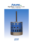
EVERGREEN • EM
INSTALLATION GUIDE
A Regal Brand
Genteq’s Evergreen EM is designed to replace OEM X13 ECM
motors quickly and easily – with no programming required.
Evergreen EM provides the same comfort, lower utility bills
and air quality as the OEM X13 ECM motor, with less hassle
for you. With Evergreen EM, increasing your bottom line
just got a little easier. For more information on all Genteq
products please visit airstarsupply.com.
944 Clint Moore Road
Boca Raton , FL 33433
1-561-989-8080
[email protected]
Part # 8794721MH Rev 2/13
®
EM
Contents
Safety Considerations .............................................................................1
Introduction/Applications ......................................................................2
Mounting............................................................................................. 3-4
Electrical Connections...................................................................... 5-10
High Voltage Power Connections....................................................6
Low Voltage Signal Connections................................................. 7-9
Final Notes........................................................................................10
Sequence of Operation .......................................................................11
Rotation Sensing.....................................................................................11
Maintenance .........................................................................................12
Reliability.................................................................................................12
Troubleshooting Guidelines............................................................. 13-15
Evergreen EM Motor Specifications.....................................................16
Please read the entire instruction manual
before starting the installation.
®
EM
Safety Considerations
The following safety warning symbol is used throughout this manual as a
safety consideration for installation and operation of the Evergreen EM motor.
This warning indicates a hazardous situation which, if not avoided, could
result in serious injury or death. Please read and observe all of these safety
concerns.
Installation and service of this motor should only be attempted by trained
service technicians familiar with the Evergreen.
This motor should be installed in accordance with accepted practices and
installation instructions, and in compliance with all national and local codes.
Always disconnect the main power from the unit being serviced before
making any wiring connections to the Evergreen EM. It is also a good
practice to confirm that the power is off with a meter.
Improper installation, adjustment, alteration, service, maintenance,
or use can cause explosion, fire, electrical shock, or other conditions
which may cause personal injury, death, or property damage. Consult
a qualified installer, service agency, or distributor for information and
assistance. The qualified installer or agency must use the supplied or
recommended parts when installing or servicing this product.
This installation/service manual enables a qualified technician to install,
service, repair, and maintain the Evergreen EM motor. This manual should be
kept near the HVAC system for future reference.
-1-
®
EM
Introduction and Features
The ultra-high-efficiency ECM has become the preferred motor for use in
energy-saving HVAC systems. Evergreen EM is made with the same fieldproven, high-efficiency ECM technology that has been used for more
than 20 years in new HVAC equipment. The Evergreen EM was designed to
replace direct-drive blower motors in residential and light commercial indoor
furnaces, air handlers, and package systems that were designed with a
standard ECM motor, such as an X13 or equivalent competitor model. It can
also be used to retrofit PSC motors in commercial building series VAV boxes
and packaged heat pump systems. It is NOT intended to replace premium
ECM constant airflow products, such as Eon 2.3, 3.0, and 2.5.
Features:
•
Multi-speed, constant torque, brushless DC motor
•
Available in 1/3, 1/2, 3/4 and 1HP ratings
•
Available in either 115VAC or 208-230VAC single-phase input, 50/60Hz
•
Maintains ECM-level Efficiency up to 80%
•
Operating speed range of 600-1200 RPM
•
Automatically determines motor direction using Genteq’s Rotation
Sensing Technology (See Rotation Sensing on page 11 for details)
•
Soft Start and Off Ramp for quieter operation
•
5 Discrete Speeds using 24VAC (3 using 18VDC) signal inputs
•
Variable Speed, Torque Control using a PWM Signal. (Motor switches to
Variable Speed mode when a PWM input is detected)
•
NEMA 48-frame (5.6 inch diameter) Belly Band Mount with 5-inch long,
½ inch diameter shaft.
•
Class B insulation
•
Electronic Thermal Overload Protection
•
UL and CSA recognized component
•
Shielded ball bearings
•
Encapsulated Electronics
-2-
®
EM
Mounting
Always disconnect the main power from the unit being serviced before
disconnecting any wiring or removing any components. It is also a good
practice to confirm that the power is off with a meter.
Remove the blower section from the HVAC system. Remove the existing
ECM motor from the blower section and properly dispose of the motor.
The frame size of the Evergreen EM motor is NEMA 48 (5.6” Diameter). This
is the most common frame size for indoor blower motors. The Evergreen EM
requires a belly band style mounting bracket.
-
If the existing motor mount is welded to the motor, bolted directly
to the motor, or attaches to the bearing assembly of the motor, it
cannot be used on the Evergreen EM. Genteq belly band kit 5K002
is recommended to replace the 4-lug mount shown below. See your
local distributor or theDealerToolbox.com for availability.
-
Universal belly band motor mounts in multiple sizes are available from
local distributors and theDealerToolbox.com
-
If the mounting bracket must be replaced, selecting one with the
same mounting pattern on the blower housing will save drilling new
holes in the blower section.
-
The belly band must fit the new motor properly. It should be tight
enough to prevent the motor from shifting on start-up and located
according to the diagram below.
-3-
®
EM
Mounting (CONT’D)
If a new motor mount is required
and the legs do not line up with
the original holes in the blower
housing, it is required to use a
bolt with either a lock washer
and nut or a locking nut through
the drilled hole(s). Self tapping
or sheet metal screws are not
sufficient for a long term installation
when a new hole is drilled through the thin wall of the blower housing.
When positioning the legs of the bellyband on the motor, make sure that
once the motor is mounted into the blower section, the wires exit the bottom
of the motor as installed in the air handler. This will insure that a proper drip
loop can be made with the signal and power lines.
As installed in the air
handler, the motor should
be positioned with the
connectors facing down
between the 4 and 8
o-clock position, with the
wiring harness formed
into a drip loop.
The blower wheel should be centered in the blower
housing. The wheel should also not be against the
motor bearing housing. If this is not possible while
centering the wheel, the motor should be adjusted
in the belly band. If the blower wheel is dirty, it
should be cleaned.
The blower wheel hub locking bolt should be
secured to the flat portion of the motor shaft
after the wheel has been centered in the
blower housing.
Re-install the blower section in the HVAC system and proceed to the next
page to make the electrical connections.
-4-
®
EM
Electrical Connections
The unique design of the Evergreen EM allows for multiple speed operation
using either 24VAC (18VDC) discrete inputs or variable speed, torque control
using a PWM controller.
The high voltage power terminals, (L) and (N), must be connected to a
continuous, un-switched power supply.
The motor on/off operation and speed/torque selections are connected
using the low voltage (C) and (1-5) terminals.
- With 24VAC, the Evergreen EM provides 5 speed operation using terminals
(C) and (1-5).
- With 18VDC, the Evergreen EM provides 3 speed operation using terminals
(C), (1), (3), and (5)
- With the addition of a PWM controller, the Evergreen EM provides variable
speed, torque control using terminals (C) and (1).
The Evergreen EM will automatically recognize the connected low voltage
input and operate accordingly. Each motor provides all three low voltage
control operations.
Detailed wiring for the High Voltage Power Connections and each unique
Low Voltage Signal Connections are covered in the following sections.
-5-
®
EM
Electrical Connections
High Voltage Power Connections
The Evergreen EM is designed for continuous un-switched connection to
its rated high voltage power supply. Motor operation is controlled by low
voltage signal inputs.
Always confirm the rating on the motor matches the power supply of the
system it is applied to and/or the motor it is replacing.
If a door safety switch is present, wire after the switch so power will be
disconnected when the door is removed for maintenance or service.
Always disconnect the main power from the unit being serviced before
making any wiring connections to the Evergreen EM. It is also a good
practice to confirm that the power is off with a meter.
1. Using 3/16” Female Quick Connect Terminals and 18 AWG wire, connect
the (L) and (N) terminals on the motor to any un-switched line voltage L1
and L2, Nameplate Voltage power supply.
2. Using a 3/16” Female Quick Connect Terminal and 18 AWG wire,
connect the (G) terminal on the motor to the system ground.
-6-
®
EM
Electrical Connections
Low Voltage Signal Connections
- (24VAC) Discrete Speed Operation
The Evergreen EM has 5 available speeds using 24VAC control inputs.
The inputs of the Evergreen can connect directly to the 24VAC thermostat
terminal strip or 24VAC signal outputs from the HVAC system control board.
DO NOT connect the Low Voltage SIGNAL (speed) terminals to the high
voltage power supply. Applying voltage above 30VAC to these terminals
will cause permanent damage to the motor.
1. Using a 1/4” Female Quick Connect Terminal and 22-18 AWG wire,
connect the (C) Common terminal on the motor to the 24VAC common
(C) thermostat terminal or 24VAC common side of the transformer on the
HVAC System. Make sure that this line is not connected to the side of the
transformer connected to the thermostat 24VAC (R). If it is connected to
the (R) high side of the transformer, the motor will not operate.
2. Select operating speeds by using 1/4” Female Quick Connect Terminal(s)
and 22-18 AWG wire to connect terminals (speeds) 1-5 to any 24VAC
thermostat demand or 24VAC HVAC system control board output.
-7-
®
EM
Electrical Connections
Low Voltage Signal Connections
- (18VDC) Discrete Speed Operation
The Evergreen EM has 3 available speeds using 18VDC control inputs.
DO NOT connect the Low Voltage SIGNAL (speed) terminals to the
high voltage power supply. Applying voltage above 23VDC to these
terminals will cause permanent damage to the motor.
1. Using a 1/4” Female Quick Connect Terminal and 22-18 AWG wire, connect the (C) Common terminal on the motor to the DC common on the
HVAC System control.
2. Select operating speeds by using 1/4” Female Quick Connect Terminal(s)
and 22-18 AWG wire to connect terminals (speeds) 1, 3, or 5 to any
18VDC HVAC system control board output.
-8-
®
EM
Electrical Connections
Low Voltage Signal Connections
- Variable Speed Torque Control Option
The Evergreen EM can also be controlled in a variable speed, torque control
mode using a PWM (Pulse Width Modulation) control on terminals (C) and
(1). The motor will operate from 10% - 100% output depending on the input
from the ECM PWM speed controller.
A PWM control suitable for ECM motors must meet the following
specifications:
- 15-23 VDC at 67-93Hz or 127 to 199Hz
- 10% Guaranteed On and 5% Guaranteed Off Duty Cycle
DO NOT connect the Low Voltage SIGNAL (speed) terminals to the
high voltage power supply. Applying voltage above 23VDC to these
terminals will cause permanent damage to the motor.
1. Using a 1/4” Female Quick Connect Terminal and 22-18 AWG wire,
connect the (C) Common terminal on the motor to the common on the
PWM controller.
2. Using a 1/4” Female Quick Connect Terminal and 22-18 AWG wire,
connect terminal (1) on the motor to the PWM signal on the PWM controller. Terminal (1) is setup for AUTOSWITCH. If a PWM signal is present, the
motor will switch from discrete speed outputs to variable speed, torque
control mode.
-9-
®
EM
Electrical Connections
Final Notes
Retrofit ECM PWM controllers are available from manufacturers, some of
which are listed on www.theDealerToolbox.com. Any control that meets the
specifications listed on the previous page should operate the Evergreen EM
properly. If there are questions regarding a particular add-on control or
building automation system, please call Evergreen technical support at
866-503-8566. Visit our website at www.theDealerToolbox.com for support.
Genteq is committed to helping with any special application questions that
may arise.
Once all connections are made from the Evergreen EM to the HVAC
system, ensure a proper drip loop is in place and verify it will not interfere with
the blower wheel or other system wiring.
Install the System ID Label on the HVAC system near the existing wiring diagram and enter the Evergreen EM data. Record the Horse Power (HP) of the
motor and the Date of Installation for future reference. The HP rating can be
found on the label located on the box or the motor.
Always verify the HVAC System operates in all applicable demand modes.
For VAV systems, adjustments should be made to the speed taps or ECM
PWM control input to balance the airflow per the OEM specifications.
- 10 -
®
EM
Sequence of Operation
Nameplate-rated line voltage is connected to the High Voltage POWER
terminals of the motor at all times. This voltage powers the microprocessor and the controls that drive the motor; however, the motor will only
operate when there is a demand on the Low Voltage SIGNAL terminals.
24VAC operation – When using 24VAC, the motor will turn on and off at the
speed selected with a 24VAC input. Multiple low voltage inputs can be sent
to the motor at the same time (if needed) due to the hierarchy built into the
control. Simply stated, multiple terminals can be energized at the same time.
The motor will always operate at the highest speed tap (terminals 1-5) that is
energized. There is no need to isolate one demand input from another. However, speed taps 1, 3, and 5 CANNOT be energized simultaneously, as this
particular input configuration is used to reverse the rotation sensing decision.
18VDC operation – When using 18VDC, the motor will turn on and off at the
speed selected with a 18VDC input. Multiple low voltage inputs can be sent
to the motor at the same time (if needed) due to the hierarchy built into the
control. Simply stated, multiple terminals can be energized at the same time.
The motor will always operate at the highest speed tap (terminals 1, 3 or 5)
that is energized. There is no need to isolate one demand input from another.
However, speed taps 1, 3, and 5 CANNOT be energized simultaneously, as
this particular input configuration is used to reverse the rotation sensing decision.
Variable Speed Torque Control operation – When using a PWM controller
the motor will operate at the selected setting anytime there is a PWM signal
present on terminals (1) and (C).
Rotation Sensing
The first time the Evergreen EM is powered up and receives a signal on
one of the Low Voltage Signal terminals, it will perform a Rotation Sensing
process. With this feature, the motor will automatically determine the proper
operating direction of the blower wheel by running the motor for several
seconds in each direction.
Do not turn off the “High Voltage Power” or the “Low Voltage Signal inputs”
to the motor until the motor continues to run in one direction. During Rotation
Sensing, the motor will run in both directions, up to four times if necessary, to
determine the proper operating direction. If the proper direction cannot be
determined after the forth sequence, the motor will operate in the default
direction of counter clock-wise (CCW).
Once the motor continues to run in one direction, Rotation Sensing is complete and the feature is locked out. The motor will continue to start and run
in this direction without performing Rotation Sensing even if the High Voltage
Power is disconnected.
If the final operating direction of the motor is not the proper direction for the
blower wheel, go to the “Troubleshooting Guidelines” on page 14; “Wrong
Rotation”.
- 11 -
®
EM
Maintenance
The Evergreen EM motor is permanently lubricated and requires no
maintenance.
Any signs of water damage on the replaced motor, in the HVAC system,
or on the Evergreen EM should be taken very seriously. Fix the water issues
immediately. If there are any signs of water damage to the Evergreen EM
motor, it should be replaced to prevent serious injury to the occupants and
the property.
All HVAC systems require annual maintenance to ensure maximum efficiency
and capacity. Refer to the HVAC system manual for proper inspection and
maintenance requirements. To keep the Evergreen EM motor and the air-side
components clean, install and regularly maintain high-quality, properly sized
filters.
Reliability
The Evergreen EM is built with over 20 years of field experience in ECM
indoor blower motors from Genteq, the leader in ECM technology. This 6th
generation product includes the following reliability improvements:
-
-
-
-
-
4kV surge protection
Speed limited for over current protection
Encapsulated electronics to prevent moisture damage
Ball bearings
EMI filter
- 12 -
®
EM
Troubleshooting Guidelines
The High Voltage Power terminals (L) and (N) must be connected to
nameplate rated voltage at all times. The acceptable High Voltage input
range is 90-132VAC for 115V models and 180-264VAC for 208-230VAC
models. If the motor does not operate, confirm this voltage is present at the
motor and make repairs to the HVAC system if it is not. This voltage alone
will not operate the motor. A low voltage input to terminals (C) and (1-5) is
required for motor operation. The (G) terminal on the motor should always be
connected to earth ground for safety.
24VAC will operate the motor at the respective speed when connected
properly to terminals (C) and (1-5). When troubleshooting the motor, always
check for voltage between terminals (1-5) and the (C) terminal at the motor.
-
The (C) Common terminal on the motor must be connected to the
24VAC common (C) thermostat terminal or 24VAC common side of
the transformer on the HVAC System. Make sure that this line is not
connected to the side of the transformer connected to the thermostat
24VAC (R). If it is connected to the (R) high side of the transformer, the
motor will not operate.
-
If the motor does not operate or does not appear to operate at the
desired speed, check the voltage between the applied terminal (1-5)
and (C) at the motor. The acceptable voltage range is (12-30VAC).
Correct any voltage issues. Do not assume the motor is failed unless you
have confirmed proper high and low voltage inputs at the motor.
18VDC will operate the motor at the respective speed when connected
properly to terminals (C) and (1, 3 or 5). When troubleshooting the motor,
always check for voltage between terminals (1, 3 or 5) and the (C) terminal
at the motor.
-
The (C) Common terminal on the motor must be connected to DC
common
-
If the motor does not operate or does not appear to operate at the
desired speed, check the voltage between the applied terminal (1, 3 or
5) and (C) at the motor. The acceptable voltage range is (15-23VDC).
Correct any voltage issues. Do not assume the motor is failed unless
you have confirmed proper high and low voltage inputs at the motor.
If 18VDC is applied to terminals (2) or (4), the motor will still operate.
Applying 18VDC to terminal (2) will operate the motor at MED speed.
Applying 18VDC to terminal (4) will operate the motor at HIGH speed.
- 13 -
®
EM
Troubleshooting Guidelines (CONT’D)
PWM will operate the motor anytime a proper signal is present between
terminals (C) and (1). The (C) Common terminal must be connected to the
PWM controller. Check the PWM controller specifications for the appropriate
DC signal. Check this signal at the motor on terminal (1). The specifications
required by the motor are as follows:
-
-
15-23VDC at 67-93Hz or 127 to 199Hz
10% Guaranteed On and 5% Guaranteed Off Duty Cycle
Do not assume the motor is failed unless you have confirmed proper high
voltage and PWM signal at the motor.
Wrong Rotation
If the motor is not operating in the proper direction for the blower wheel, the
rotation sensing decision will need to be altered. Following this procedure will
allow the rotation direction to be changed several times.
ALWAYS DISCONNECT MAIN HVAC SYSTEM POWER BEFORE
DISCONNECTING OR RE-CONNECTING ANY WIRES OR CONNECTORS TO
THE EVERGREEN MOTOR.
1. Disconnect the main power to the HVAC system.
2. Disconnect the Low Voltage Control Input connections(s) from the motor.
- 14 -
®
EM
Troubleshooting Guidelines (CONT’D)
3. Connect motor terminals 1, 3, & 5 to either 24VAC or 18VDC and
Common to terminal C.
4. Reconnect the main power to the HVAC system.
5. Energize motor terminals 1, 3, & 5 with either 24VAC or 18VDC and
Common to terminal C continuously for a minimum of 5 minutes.
6. Disconnect the main power to the HVAC system for a minimum of 3
minutes.
7. Disconnect the 24VAC or 18VDC from motor terminals 1, 3, & 5 and
Common from terminal C.
8. Reconnect the Low Voltage Control Input connection(s) to the motor.
9. Reconnect the main power to the HVAC system.
If the motor continues to operate in the wrong direction, repeat this
procedure carefully and confirm all timings. If after several attempts,
changing the rotation has not been successful, please call the Evergreen
Hotline at 866-503-8566.
Replacing the Evergreen EM
If the motor does not operate with proper High Voltage Power and low
voltage communication present at the motor, it is failed and will require
replacement. Before replacing the motor, please call the Contractor
Hotline to confirm your diagnostics if possible. The Evergreen EM is a single
component replacement. The control cannot be replaced separately from
the motor. Contact the distributor where the motor was purchased or any
authorized Evergreen distributor for replacement.
If the troubleshooting guidelines provided here do not solve the problem
or you have a problem not listed here, please contact the Evergreen
Contractor Hotline 1-866-503-8566. Additional support is available at
www.theDealerToolbox.com.
- 15 -
®
EM
Motor Specifications
Evergreen EM is an UL and CSA recognized component. The models listed
here are all either 115VAC or 208-230VAC. The allowable voltage range is
90-132 VAC for 115VAC models and 180-264VAC for 208-230VAC models.
Additional models may be available. See theDealerToolbox.com for more
details.
The frame size of all Evergreen EM motors is NEMA 48 (5.6” diameter). All
shafts are 1/2” diameter, 4.92” long, with a single flat. See the listings below for
each motors respective dimension from end shield to end shield (Dim. B) and
end shield to shaft end (Dim. A).
1/3 HP
Models
1/2 HP
Models
3/4 HP
Models
1 HP
Models
Voltage
Stock #
Max
Current
115V
6103E
4.8A
208-230V
6203E
2.8A
115V
6105E
6.8A
208-230V
6205E
4.1A
115V
6107E
8.4A
208-230V
6207E
6.0A
115V
6110E
10.9A
208-230V
6210E
7.6A
Dim. A
Dim. B
Approximate
Weight
10.17”
5.25”
8.4 lbs.
10.67”
5.75”
11.3 lbs.
11.42”
6.5”
15.6 lbs.
12.17”
7.25”
19.3 lbs.
®
EM
Ambient Temperature of all motors listed here.
Storage: -40 to +85 degrees Celsius (-40 to 185 degrees Fahrenheit)
Powered, not operating: -20 to +65 degrees Celsius (-4 to 149 degrees
Fahrenheit)
Operating (1/3 and 1/2 Hp): -20 to +55 degrees Celsius (-4 to 131 degrees
Fahrenheit)
Operating (3/4 and 1 Hp): -20 to +45 degrees Celsius (-4 to 113 degrees
Fahrenheit)
- 16 -
Need Additional Help?
Contractor Hotline:
1.866.503.8566
thedealertoolbox.com
®
A Regal Brand
1946 West Cook Road
Fort Wayne, IN 46818
1-866-503-8566
thedealertoolbox.com
© 2013 Regal-Beloit Corporation Part #8794721MH
7377X/11-12/2.5K/BH/TG
Rev 2 /13