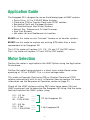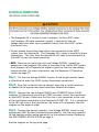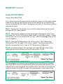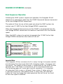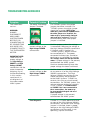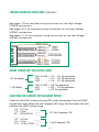
1
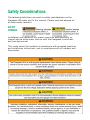
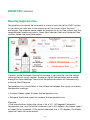
Installation Guide
www.EvergreenDealer.com
www.theDealerToolbox.com
GE ECM
By REGAL-BELOIT
GE ECM
By REGAL-BELOIT
1946 Cook Road
Fort Wayne, IN 46818
1-866-503-8566
www.theDealerToolbox.com
Evergreen™ IM Installation Guide
© Copyright 2008
Regal Beloit Corporation
The information in this document is subject to change without notice.
Rev 12/08
Table of Contents
Safety Considerations . ............................................................... 1
Introduction .............................................................................. 2
Application Guide ...................................................................... 3
Motor Selection ......................................................................... 3
Pre-Installation Notes ................................................................ 4
Installation Guide ................................................................. 5-15
Mounting the Evergreen IM ................................................ 5-6
Electrical Connections ..................................................... 7-15
High Voltage Power ...................................................... 7-8
High Voltage Signal .................................................... 9-10
Low Voltage Signal ................................................... 11-12
Special Applications . .................................................... 13
Continuous Fan Operation .............................................. 14
Final Notes . ................................................................. 15
Airflow Tests . ..................................................................... 16-20
Sequence of Operation ........................................................ 21-26
Maintenance ........................................................................... 26
Troubleshooting Guidelines .................................................. 27-32
Installation Worksheet............................................................... 33
Contractor Hotline .........................................................Back page
Please read the entire instruction manual
before starting the installation.
Safety Considerations
The following definitions are used as safety considerations on the
Evergreen IM motor and in this manual. Please read and observe all
of these safety concerns.
SAFETY
SYMBOLS
Installation and service of this motor should be attempted only by
trained service technicians familiar with the Evergreen instructions
and training manual.
This motor should be installed in accordance with accepted practices
and installation instructions, and in compliance with all national and
local codes.
-1-
Introduction
The Evergreen IM is an ECM (Electronically Commutated Motor) designed
to replace an existing PSC (Permanent Split Capacitor), direct drive,
indoor blower motor. It is constructed with over 20 years of Proven ECM
technology and reliability.
This installation/service manual enables a qualified technician to install,
service, repair and maintain the Evergreen IM motor. This manual is to
be left near the HVAC system for future reference. Due to the advanced
multi-function of this motor it is highly recommend that you read the
entire manual before beginning any job to make sure it is the correct
motor for the HVAC System it is being applied to.
This unique ECM motor will operate and connect to the HVAC systems
controls much differently than the replaced PSC motor. For proper, safe
and efficient operation please read the entire manual before attempting
any wiring connections.
When properly installed the Evergreen IM will maintain the sequence of
operation and safety operations of the HVAC System.
On page 33 of this manual is an Installation Worksheet provided to
write down all the critical information for the selection, installation
and airflow testing.
Included with this motor for help with installation and wiring connections
are the following:
• 115VAC white jumper
• Optional Y-adapter
• 230VAC yellow jumper (installed on motor)
• HVAC System ID Label
-2-
Application Guide
The Evergreen IM is designed for use on the following types of HVAC systems:
• Direct Drive, 115 or 230VAC Motor Systems
• Clock-wise (CW) or Counter Clock-wise (CCW) rotation
• Residential Split and Packaged Systems
• Air Conditioning or Heat Pump Systems
• Natural Gas, Propane and Oil Heat Furnaces
• Dual Fuel Systems
• Hot water coil and Geothermal air handlers
DO NOT use this motor on any “twinned” furnace or air handler systems.
DO NOT use this motor to replace any existing ECM other than a direct
replacement of an Evergreen IM.
The 1/2 Hp motor will replace 1/5, 1/4, 1/3 and 1/2 Hp PSC motors
The 1 Hp motor will replace 1/2 and 3/4 Hp PSC motors
Motor Selection
Confirm the motor is applicable to the HVAC System using the Application
Guide above.
Confirm the motor being replaced is a direct drive indoor blower motor
operating at 115 or 230VAC. This is a dual voltage motor.
This motor will operate Clock-wise (CW) or Counter Clock-wise (CCW)
rotation automatically with its built in Rotation Sensing feature. For more
information see the Sequence of Operation section on page 21.
Check off the HVAC systems existing PSC motor horse power (Hp) and
HVAC equipment size to determine the Evergreen IM sizing. Use the motor
that best matches the HVAC system sizing.
1/5 - 1/2 Hp
____
1.5 - 3 Ton
____
40 - 100k BTUH ____
1/2 Hp Evergreen IM
1/2 - 3/4 Hp
____
3.5 - 5 Ton
____
110 - 150k BTUH ____
1 Hp Evergreen IM
-3-
Pre-Installation Notes
Before removing the existing motor, check off the existing speed selections,
in each mode of operation, in the spaces below. If the motor is operational,
also record the Total External Static Pressure (TESP) and/or the Temperature
Rise (TR) in each mode of operation. This information will help select the
new motor speeds.
Heat Pump Systems
Cooling/Heating Speed Hi___ MHi___ MLo___Lo___ TESP____
Cooling/Heating Speed Hi___ MHi___ MLo___Lo___ TESP____
(1st Stage)
Emer. Heat Speed
Hi___ MHi___ MLo___Lo___ TESP____ TR___
Furnace Heat Speed
Hi___ MHi___ MLo___Lo___ TR___
Furnace Heat Speed
(1st Stage)
Hi___ MHi___ MLo___Lo___ TR___
Air Conditioning and/or Gas, Propane or Oil Heating Systems
Cooling Speed
Hi___ MHi___ MLo___Lo___ TESP____
Cooling Speed
(1st Stage)
Hi___ MHi___ MLo___Lo___ TESP____
Heating Speed
Hi___ MHi___ MLo___Lo___
Heating Speed
(1st Stage)
Hi___ MHi___ MLo___Lo___
NOTE: The HVAC Systems fan control connections, where the existing PSC
motor is connected, will be used to operate the Evergreen IM. Make note
of the terminals that the old motor connected to for heating and/or cooling
operation before removing the motor wires.
-4-
Installation Guide
Mounting the Evergreen IM
Remove the blower section from the HVAC system. Remove the existing PSC
motor from the blower section. Properly dispose of the motor and the run
capacitor. The Evergreen IM motor does not require a run capacitor.
The frame size of the Evergreen IM motor is NEMA 48 frame. This is the
most common frame size for indoor blower motors. If the original motor
has the same frame size, the original mounting bracket should work on
the Evergreen IM. The Evergreen IM requires a belly band style mounting
bracket. The original mounting bracket can be used as long as it is belly
band style with no special bolts or bearing mounts. Torsion flex brackets
can be used on the ½ Hp motor only. They are not approved for the 1 Hp
motor due to noise and longevity.
If the mounting bracket must be replaced, selecting one with the same mounting
pattern on the blower housing will save drilling new holes in the blower section.
The belly band must fit the new motor properly. It should be tight enough to
prevent the motor from shifting on start-up and not cover any vents. On ECM
motors the belly band must not be placed over the motor control section.
NOTE: when attaching the bellyband mount, make sure it is not located in the
“Keep Out Area” area.
-5-
Mounting the Evergreen IM (continued)
If a new motor mount is required and the legs do not line
up with the origonal holes in the blower housing, it is
required to use a bolt with either a lock washer and nut
or a locking nut through the new drilled hole(s).
Self tapping or sheet metal screws are not a sufficient
long term installation when a new hole is drilled through
the thin wall of the blower housing.
When positioning
the legs of the
bellyband on the
motor, make sure
that once the motor
is mounted into
the blower section,
the wires come out
towards the bottom
of the motor as
installed in the air
handler. This will
ensure that a proper drip loop can be made with the signal and power lines.
The blower wheel should be centered in the blower
housing. The wheel should also not be resting up
against the motor bearing housing. If this is not
possible while centering the wheel the motor should
be adjusted in the belly band. If the blower wheel is
dirty, it should be cleaned.
The blower wheel hub locking bolt should be secured
to the motor shaft on the flat portion of the shaft, after
the wheel has been centered in the blower housing.
Re-install the blower section in the HVAC system
and proceed to the next page to make the electrical
connections.
-6-
Electrical Connections
High Voltage POWER Connections
• The Evergreen IM is connected to line (High) voltage power at ALL TIMES. • Do not connect the High Voltage Power leads of the Evergreen IM motor to
any relays or switched circuit board terminals.
• If a door switch is present, wire after the switch so power will be
disconnected when the door is removed for service or maintenance.
• If the HVAC system has multiple line voltage circuits (typically on
systems with multiple heat strips), connect the Evergreen IM to the
same circuit that powered the main/fan control board or fan relay for
the original motor.
• This motor is capable of operation from 115 or 230VAC line voltage with the
proper application of the voltage jumper.
Step 1: Install the proper voltage jumper for the system the motor will be
installed in. To change the voltage jumper DISCONNECT MAIN POWER,
remove the 4-pin high voltage plug first, then change out the voltage jumper
and re-install the 4-pin high voltage plug. For 230VAC systems the
YELLOW jumper should be factory installed.
For 115VAC systems,
remove the YELLOW
230VAC jumper
and install
the WHITE
115VAC jumper.
-7-
Electrical Connections
High Voltage POWER Connections (CONTINUED)
Step 2: Cut the High Voltage POWER harness to the length needed (leave
a little extra) to reach the desired line voltage connection point.
Step 3: Strip the insulation back to connect bare wires or install terminals
as needed.
Step 4: Connect the Black L1 wire to Line Voltage L1 on either 115 or
230VAC systems.
Step 5: Connect the White L2 to Neutral on 115VAC systems or Line Voltage
L2 on 230VAC systems.
Step 6: Connect the Green w/Yellow strip ground wire to system ground.
-8-
Electrical Connections
High Voltage SIGNAL Connections
These connections are rated for 115VAC. On 230VAC motor systems, the
HVAC fan controls may switch L1 or L2, which is within the 115VAC rating.
• The High Voltage SIGNAL connections communication tell the Evergreen
IM when to turn on and off according to the HVAC systems original fan
control or fan relay outputs. This maintains the operational integrity of
the HVAC System.
• These connections will also determine the output horse power (Hp) of the
Evergreen IM. The output Hp of the Evergreen IM should be set to match the
Hp rating of the PSC motor that was removed.
• Due to the multi-purpose application of this motor it would be
impossible to provide a wiring diagram for each unique HVAC System it
could be used on. The diagram on the following page shows all potential
HVAC System high voltage fan operation outputs.
• Depending on the HVAC System, there may be only one or up to four
individual fan control connections necessary. These can be identified
using the existing HVAC Systems wiring diagram or following where the
replaced motor speed(s) were connected.
Step 1: Identify the horse power (Hp) rating of the replaced PSC motor.
Use the following chart to determine which High Voltage SIGNAL (HV)
connection(s) to use.
1/2 Hp Motor
HV1 & HV2 = 1/2 - 1/3 Hp operation
HV1 = 1/3 - 1/4 Hp operation
HV2 = 1/4 - 1/5 Hp operation
1 Hp Motor
HV1 & HV2 = 3/4 Hp operation
HV1
= 3/4 – 1/2 Hp operation
HV2 = 1/2 Hp operation
-9-
Electrical Connections
High Voltage SIGNAL Connections (CONTINUED)
Step 2: Identify where the replaced PSC motor was connected to the
HVAC Systems fan control(s) for heating and/or cooling fan operation.
Fan control connections could be on a main circuit board, a separate
fan control circuit board, or individual fan relay.
Step 3: Cut the High Voltage SIGNAL harness to the length needed
(leave a little extra) to reach the HVAC system controls.
Step 4: Connect the High Voltage SIGNAL connection(s) from
the Evergreen motor (selected from the Chart in Step 1) to ALL of the
applicable HVAC Systems fan connection(s) according to the diagram
below. If the HVAC systems fan controls have a separate Constant
Fan motor tap, include this tap in the connections made here.
HVAC Systems fan
control connections.
These connections
could be on a circuit
board, relay and/or
fan switch.
HVAC Systems fan
control connections.
These connections
could be on a circuit
board, relay and/or
fan switch.
HVAC Systems fan
control connections.
These connections
could be on a circuit
board, relay and/or
fan switch.
- 10 -
Electrical Connections
low Voltage signal Connections
• The Evergreen IM is unique in how it operates. Unlike a PSC motor,
the Evergreen IM motor operation (speed) is selected by the low
voltage communication inputs powered directly from the HVAC system
thermostat lines.
• Do not remove the existing thermostat lines connected to the HVAC
system from the thermostat. The Evergreen IM is wired in parallel to these
connections. The lines from the thermostat still need to be connected to
the HVAC system for correct operation.
• NOTE: There can be more than one Low Voltage SIGNAL (speed) tap
powered on the Evergreen IM motor at the same time. Unlike PSC motors,
the Evergreen IM will operate the highest speed tap that has low voltage
communication. For more information, see the Sequence Of Operation
section on page 21.
Step 1:
Cut the Low Voltage SIGNAL harness to the length needed (leave
a little extra) to reach the HVAC system thermostat connections.
Step 2:
Strip the insulation back to connect bare wire or install terminals
as needed to the appropriate speed selections determined below.
Step 3:
Connect the Low Voltage SIGNAL wire COMMON to the 24VAC
common (C) thermostat terminal or 24VAC common side of the transformer
on the HVAC System. Make sure that this line is not connected to the side
of the transformer connected to the thermostat 24VAC (R). If it is connected
to the (R) high side of the transformer, the motor will not operate. See the
diagram on the opposite page.
Step 4:
Connect the desired speed(s), Low Voltage SIGNAL wire(s) to the
appropriate HVAC System thermostat connection(s). Use the same speed(s)
for the heating and/or cooling demand(s) as the replaced motor. Reference
the PRE-INSTALLATION NOTES on page 4.
See the diagram on the opposite page.
- 11 -
Electrical Connections
low Voltage signal Connections (Continued)
Most HVAC systems use the same terminal designations for their thermostat
demands. However there are variations. If the terminal designations in the
HVAC system being connected to are different than the ones used in our
diagrams, match them up to the operation of our generic listing below.
Air Conditioning Systems with or without Electric Strip Heat
Y ——— Call for cooling on single stage systems
Y1——— Call for first stage cooling on two stage systems
Y2——— Call for second stage cooling on two stage systems
W ——— Call for heating (electric strips)
Heat Pump Systems with or without Electric Strip Heat
Y— —— Call for heating and cooling (operates the outdoor
unit contactor)
W2——— Call for Emergency Heat
Gas, Propane or Oil Heat Systems
W——— Call for heating on single stage systems
W1——— Call for first stage heating on two stage systems
W2——— Call for second stage heating on two stage systems
The (G) continuous fan connection from the thermostat is not required on the
Evergreen IM for continuous fan operation. A special high efficiency fan speed
will be energized automatically if constant fan is energized from the thermostat
through the High Voltage SIGNAL connection(s). If continuous fan operation is
desired at a higher airflow, see the Special Applications section on page 14.
See the next page for any SPECIAL APPLICATIONS and/or continue with the
FINAL ELECTRICAL CONNECTION NOTES on page 15.
- 12 -
Electrical Connections
special applications
If the HVAC System this motor is applied to uses a separate speed for
each heating and/or cooling demand including two-stage systems, this page
is not needed.
Systems that require the same speed for heating and/or cooling demands.
For Example:
• Heat Pump Systems with or without emergency electric strip heat.
• Air Conditioning Systems with electric heat.
• Large furnaces connected to a small air conditioning or heat pump.
• Systems with multiple stages and overlapping airflow requirements.
To allow the motor to operate at the same speed from two different thermostat
demands, the special 24 VAC Y-adapter included in the box must be used.
DO NOT attempt to use any other method to wire two thermostat lines to the same
speed. The Y-adapter is specially designed for this application to prevent
voltage feedback, and the operation of multiple demands at the same time.
Only the MED-HI and Low speeds can be used with the Y adapter. If HI or MED-LOW
is found to be the required airflow for two system demands another speed will have
to be used for one of the demands, or the Evergreen IM should not be applied to
that system. In most cases the speeds of the Evergreen IM are close enough in
airflow range to select another speed for one of the demands.
- 13 -
Electrical Connections
Continuous fan operation
High Efficiency Constant Fan Operation
The Evergreen IM will automatically operate a fixed high efficiency low
constant fan airflow without a (G) fan connection to the Low Voltage
SIGNAL (speed) taps. When the HVAC System receives a 24VAC (G)
command from the thermostat to the fan controls, they will send 115VAC
to the High Voltage SIGNAL connection(s). If the motor receives voltage on
the High Voltage SIGNAL connection(s) with no voltage on the Low Voltage
SIGNAL connections, the motor will operate at the special high efficiency
low constant fan airflow automatically. See the Sequence of Operation
section on page 26 for more information.
Increasing Constant Fan Airflow
If more airflow is desired during constant fan operation there are two options.
Option 1: Connect any of the Low Voltage SIGNAL (speed) taps on the motor
not being used by a heating or cooling demand to the 24VAC constant fan (G)
thermostat demand.
Option 2: If the speed desired for constant fan is currently being used by a
heating or cooling demand, and that speed is HI or MED-LOW, another speed
will have to be used.
If the speed desired is LOW or MED-HI, use the 24VAC Y-adapter to connect
the LOW or MED-HI (speed) Low Voltage SIGNAL (speed) tap on the motor
to the 24VAC Y-adapter and connect the Y-adapter to the heating or cooling
24VAC thermostat demand required by that speed and the 24VAC constant
fan (G) thermostat demand.
- 14 -
Electrical Connections
final notes
GE ECM by REGAL BELOIT is committed to helping with any special
wiring or application questions. We have provided more example wiring
diagrams if needed on our website at www.EvergreenDealer.com.
If immediate assistance is required you may contact technical support
on the Evergreen Contractor Hotline at 1-866-503-8566.
When finished connecting all of the Evergreen IM wires to the system, create
the recommended drip loop, and assure it will not interfere with the blower
wheel or other system wiring.
It is ok to leave extra wire, especially the unused speeds. Tie them to the
harness for future use if needed. Even though the extra speed and High Voltage
SIGNAL wires will have no voltage or current on them, it is a good practice to
wire nut and tape these unused leads.
Install the System ID Label on the HVAC system near the existing wiring
diagram and enter the Evergreen IM data. Record the Horse Power (Hp) of the
motor and the Date of Installation for future reference if needed. The motors
Hp rating can be found on the label located on the box.
Always verify the HVAC System operation in all demand modes applicable, heating,
cooling and continuous fan.
Always verify the airflow in all demand modes by following the instructions in the
next section on “Airflow Tests”.
- 15 -
Airflow Tests
After installing the Evergreen IM motor it is important to verify that the speed
tap(s) selected will provide the proper airflow in all modes of operation for
maximum performance, comfort, capacity and safe operation.
Before checking the airflow all filters should be cleaned or replaced. All grilles,
balancing dampers and registers should also be clear and open.
Recommended Set-up
Confirm airflow is matched to the systems performance requirements:
• Measure airflow with industry accepted instruments
• Adjust the temperature rise on all fossil fuel heating systems to meet
the OEM data plate specifications.
• Adjust the speed selections to achieve the design CFM (Cubic Feet per
Minute) per ton of cooling.
Airflow and temperature measurements are often inaccurate without traversing
the measured area. This applies to measurements taken inside the duct and at
the return grille and supply registers. A traverse is typically 5 or more readings
across the area of the airflow measurement. To find the average, add all
readings together and divide by the number of readings taken.
Measuring the Total External Static Pressure (TESP) cannot be used to
determine airflow with the HVAC System manufacturer’s chart since those
charts were not designed with the Evergreen IM motor.
However, most manufacturers rate their systems operation up to a maximum of
.8 – 1.0 inches of water column. If the TESP is higher than the manufacturer’s
recommendation for that system, the airflow issues must be corrected.
The Evergreen IM will not compensate for severe airflow restrictions.
- 16 -
airlow tests (continued)
Gas, Propane and Oil Heating Systems
Confirm system operation by operating the furnace (in both first and second
stage on two stage furnaces) and measuring the Temperature Rise. The
Temperature Rise should fall within the required values supplied on the
HVAC Systems manufacturer data plate.
• Gas pressure should be set to the value listed on the HVAC Systems data
plate.
• System should be at operating temperature (Steady State Condition) before
taking temperature readings. The typically accepted time frame is 15
minutes or until the temperature rise and/or stack temperature has stabilized.
• If the temperature rise does not fall within the values listed on the HVAC
Systems data plate, adjust the Low Voltage SIGNAL (speed) tap connected
to the 24VAC thermostat heating demand up or down and take the readings
again. Repeat as needed to attain the proper temperature rise.
An operating temperature rise that is lower than the manufacturer’s
recommendation can cause increased heat exchanger condensation.
An operating temperature rise that is higher than the manufacturer’s
recommendation can cause system failure on high limit. Both of these
situations can decrease the life of the heat exchanger.
It is highly recommended that a Carbon Monoxide (CO) measurement be
taken on all fossil fuel furnaces at the conclusion of all service calls. Below
is a listing of recommended levels of CO in the flue gas and in the home.
AGA (American Gas Association)
ANSI Standard (American National Standards Institute)
200ppm Air-Free = maximum allowed from an unvented space heater
400ppm Air-Free = maximum allowed in vented appliances flue gas
800ppm Air-Free = maximum allowed from unvented gas ovens
According to the EPA, no standards for CO have been agreed upon for indoor
air. The U.S. National Ambient Air Quality Standards for outdoor air are 9ppm
for 8 hours, and 35ppm for 1 hour. Any CO level found in a home that is higher
than the outdoor reading should be investigated.
- 17 -
airlow tests (continued)
Measuring Temperature Rise
Temperature rise should be measured as close as possible to the HVAC system
in the return air inlet and in the supply out of the line of site of the heat
exchanger. The diagram below shows an example of an up flow system and the
recommended measuring points. Down flow (counter flow) and horizontal flow
systems follow the same parameters.
If access to the ductwork close to the furnace is not possible, use the closest
return grille and supply register. Analog or digital thermometers are accurate
enough for these readings. Some dual temperature meters will automatically
calculate the difference.
Temperature rise is calculated as the difference between the supply and return
temperature readings.
• Increase blower speed to lower the temperature rise.
• Decrease the blower speed to increase the temperature rise.
Example:
If the manufactures data plate rating is for a 30 – 60 degrees Fahrenheit
temperature rise, and the actual measured rise is 65 degrees, the blower speed
will need to be increased. If the actual measured rise is 25 degrees, the blower
speed will need to be decreased.
- 18 -
airlow tests (continued)
Air Conditioning and Heat Pump Systems
These systems are designed to operate with a specified amount of airflow
measured in Cubic Feet per Minute (CFM). Whenever possible use the
manufacturer’s literature as the specification of recommended airflow. For two
stage systems, only the manufacturer’s manual can provide the data for 1st
Stage airflow requirements.
The typically recommended CFM per ton of single stage (or second stage
on two stage systems) cooling is 400, where one ton of cooling equals
12,000BTUH rating on the manufacturer’s data plate. If your region dictates
a higher or lower CFM per ton, use that value.
There are many ways to measure the CFM. The HVAC System should be
operating in the cooling mode with a dry evaporator coil. If the CFM measured
does not meet the required CFM of the system, adjust the Low Voltage SIGNAL
(speed) tap connected to the 24VAC thermostat demand up or down and take
the readings again. Repeat as needed to attain the proper CFM.
Velocity Method
CFM = Velocity x Area
Velocity = Feet Per Minute (FPM)
Area = Square Feet
Square Feet = Square Inches divided by 144
Square Inches = Height x Width
• Measure the velocity of the air in a duct, multiplied by the cross sectional
area of the duct (H x W) in square feet.
• Measure the velocity of the air entering a single main return grille, multiplied
by the cross sectional free area of the grill. Remove the filter on filter grilles.
Evaporator Coil Pressure Drop Charts
If available, the manufacturer’s indoor coil pressure drop charts are also an
effective way to measure airflow. Measure the static pressure drop across the
indoor coil and adjust the speed of the motor until the pressure drop equals
the desired airflow on the chart.
- 19 -
airlow tests (continued)
Temperature Rise Method
Electric Strip Heat ONLY
This method requires the operation of the electric strips and the indoor blower
motor only by setting the thermostat to call for heat (W) on air conditioning
systems with electric strip heat or emergency heat (W2) on heat pump systems
with electric strips.
Step 1. Operate only the electric strips and the indoor blower on the speed
of choice for this measurement.
Step 2.
Measure the voltage and total amperage of the electric strip(s) and
the indoor fan. Do this at the main power supply in the HVAC system. If there
are multiple circuits for multiple sets of strips, add the amperage from all the
circuits together.
Step 3. Calculate the temperature rise of the system.
See “Measuring
Temperature Rise” on page 18 for help if needed. For the purpose of this
formula, temperature rise is listed as TD (Temperature Difference).
Step 4. Using the numbers that you have calculated for the system, plug
them into the formula below to calculate the system’s CFM.
The temperature rise method can be used on fossil fuel furnaces; however,
the Output BTUH must be confirmed by either adjusting the manifold gas
pressure to the specification on the manufacturer’s data plate, or clocking the
meter to confirm Input BTUH meets the manufacturer’s data plate listing.
- 20 -
Sequence of Operation
When connected properly, the Evergreen IM will operate following the same
sequence of operation as the replaced motor according the HVAC Systems
demands and delays.
Line voltage (115 or 230 VAC) is connected to the High Voltage POWER
connections on the motor at all times. This voltage powers the microprocessor
and the controls that drive the motor. However, the motor will only be driven
when there is a communication demand on the Low Voltage and/or High
Voltage Signal connections.
The Low Voltage SIGNAL connections determine what speed the motor
will operate at. This voltage alone cannot operate the motor. It can only
communicate to the motor what level (speed) of operation is desired.
The High Voltage SIGNAL connections are the on/off communication for the
motor, as well as the determination of operational horse power.
Rotation Sensing
The first time the Evergreen IM is powered up and receives communication
on both the “High Voltage POWER” connections and “High Voltage SIGNAL”
connections, it will operate its Rotation Sensing feature. With this feature
the motor will automatically determine the proper operating direction of the
blower wheel without any wiring to configure.
During rotation sensing, the motor will turn on and off, running for a couple
of seconds in each direction, sometimes but rarely more than twice before
operating in the proper direction.
Do not turn off the “High Voltage POWER” or the “High Voltage SIGNAL” to the motor
until the motor continues to run in one direction for more than 60 seconds. During
rotation sensing the motor may start and stop in both directions a maximum of
four times if needed to determine the proper operating direction. If the proper
direction cannot be determined after the forth sequence the motor will operate
in the default direction of counter clock-wise (CCW).
After the motor has been running in one direction for more than 60 seconds,
the rotation sensing feature is locked out. The motor will continue to start in
this direction without performing the rotation sensing feature even if the
“High Voltage POWER” is disconnected.
If the final operating direction of the motor is not the proper direction for the
blower wheel, go to the “Troubleshooting Guidelines” on page 32 “The motor is
operating in the wrong direction”.
- 21 -
Sequence of Operation (continued)
Basic Sequence of Operation
Following the HVAC systems sequence of operation, the Evergreen IM will
determine its operational speed from the 24VAC thermostat demand connected
to the Low Voltage SIGNAL connections.
The motor will then turn on at that speed only when the HVAC systems fan
controls send 115VAC to the High Voltage SIGNAL connections.
When the thermostat demand ends and the 24VAC is de-energized from the
Low Voltage SIGNAL connections the motor will continue to run at a reduced
speed.
When the HVAC systems fan controls de-energize the 115VAC to the High
Voltage SIGNAL connections the motor will turn off.
Important Note:
The Evergreen IM has numerous built in ramp timings to improve comfort
and decrease the noise associated with changing speeds, turning on and
turning off. The length of these ramps is determined by the HVAC System
demand and if the motor is currently on, off or running constant fan.
The following pages will cover each specific operation. It is important
to understand that a ramp is different than a delay. A delay waits for
a specified amount of time before action. A ramp uses the specified
amount of time to change the motor operation from off to on, on to off
or from one speed to another.
- 22 -
Sequence of Operation (continued)
Single Demand Time Line
Motor On Command
1. HVAC System demand energizes 24VAC from thermostat connection to a
Low Voltage SIGNAL (speed) tap. There is no motor operation at this point
unless Step 2 occurs at the same time according the HVAC Systems fan
control(s) sequence of operation. This allows the HVAC System to maintain
any built in fan on delays.
2. HVAC System fan control(s) energize 115VAC to the High Voltage SIGNAL
connection(s). Motor will ramp (15 second maximum ramp) up to the Low
Voltage SIGNAL (speed) tap selection.
Motor Off Command
1. HVAC System demand de-energizes 24VAC from thermostat connection to
the Low Voltage SIGNAL (speed) tap.
2.The motor will ramp down to a fixed reduced speed setting. Minimum ramp
time 45 seconds. After 45 seconds the motor will continue to operate at
the fixed reduced speed setting until the High Voltage SIGNAL connection(s)
are de-energized. This allows the HVAC System to maintain any built in fan
off delays.
3. HVAC System fan control(s) de-energize 115VAC from the High Voltage
SIGNAL connection(s). Motor will ramp (15 second maximum ramp) to off.
If this voltage is de-energized at the same time as Step 1 or during the ramp
down specified in Step 2, the motor will begin its off ramp immediately.
The Low Voltage SIGNAL (speed) taps on the Evergreen IM are communication
inputs, not motor windings like a PSC motor. The microprocessor is programmed
to look at these taps for an operating (speed) value only. There can be more
than one (speed) tap energized at the same time without damaging the motor.
The next sections will cover the sequence of operation for multiple demands
and demand changes on the Low Voltage SIGNAL (speed) tap selections.
- 23 -
Sequence of Operation (continued)
Multiple Demand Time Line
If multiple 24VAC thermostat demands are energized at the same time to
the Low Voltage SIGNAL (speed) tap selections on the motor, it is designed
to operate at the highest value tap selection and ignore the communication
voltage on the lower value tap(s). Value equals the Low Voltage SIGNAL (speed)
taps where high speed is the highest value and low speed is the lowest value.
Examples:
Air Conditioning or Heat Pump call on Y and G
Two Stage System call on both stages
Motor On Command
1. HVAC System demand energizes 24VAC from thermostat connections to
multiple Low Voltage SIGNAL (speed) taps. There is no motor operation
at this point unless Step 2 occurs at the same time according the HVAC
Systems fan control(s) sequence of operation. This allows the HVAC System
to maintain any built in fan on delays.
2. HVAC System fan control(s) energize 115VAC to the High Voltage SIGNAL
connection(s). Motor will ramp (15 second maximum ramp) up to the
highest value Low Voltage SIGNAL (speed) tap selection that is energized.
Motor Off Command
1. HVAC System demand de-energizes 24VAC from thermostat connections
to all of the Low Voltage SIGNAL (speed) taps.
2. The motor will ramp down to a fixed reduced speed setting. Minimum
ramp time 45 seconds. After 45 seconds the motor will continue to
operate at the fixed reduced speed setting until the High Voltage SIGNAL
connection(s) are de-energized. This allows the HVAC System to maintain
any built in fan off delays.
3. HVAC System fan control(s) de-energize 115VAC from the High Voltage
SIGNAL connection(s). Motor will ramp (15 second maximum ramp) to off.
If this voltage is de-energized at the same time as Step 1 or during the ramp
down specified in Step 2, the motor will begin its off ramp immediately.
- 24 -
Sequence of Operation (continued)
Demand Changes During HVAC System Operation
If there is an HVAC System demand change while the motor is operating, the
motor will ramp, up or down, to the new speed of highest value. Value equals
the Low Voltage SIGNAL (speed) taps where high speed is the highest value
and low speed is the lowest value.
Examples:
Two stage systems changing from one stage to another
Dual Fuel system changing from heat pump to fossil fuel heating
If the HVAC System and motor are in full operation, with a 24VAC thermostat
demand already energizing one or more Low Voltage SIGNAL (speed) taps and
the High Voltage SIGNAL connection(s) are energized, the following sequences
would occur.
1. If a new 24VAC thermostat demand energizes a (higher value) Low Voltage
SIGNAL (speed) tap than is currently energized, the motor will ramp
(minimum 45 seconds ramp) to the new higher speed.
2. If a new 24VAC thermostat demand energizes a (lower value) Low Voltage
SIGNAL (speed) tap than is currently energized, the motor will ignore that
communication.
3.If a (higher value) Low Voltage SIGNAL (speed) tap is de-energized while one
or more (lower value) taps are still energized, the motor will ramp (minimum
45 seconds ramp) to the next (highest value) tap that is energized.
When the last Low Voltage SIGNAL (speed) tap is de-energized, the
motor will follow the same sequence as described in the previous sections
“Motor Off Command”.
Constant fan operation
If the 24VAC thermostat constant fan (G) line is connected to a Low Voltage
SIGNAL (speed) tap, and the thermostat is set to Fan On, the HVAC Systems
fan controls will energize the High Voltage SIGNAL connection(s) and the
motor will run at that speed continuously. With the High Voltage SIGNAL
connection(s) energized, the motor will ramp up (up to 45 seconds maximum
ramp) to any new (higher value) Low Voltage SIGNAL (speed) tap energized
from a system demand. At the end of all other demands, the motor will ramp
down (up to 45 seconds maximum ramp) to the Low Voltage SIGNAL (speed)
tap still energized by the (G) line.
- 25 -
Sequence of Operation (continued)
High Efficiency Constant Fan Operation
If the 24VAC thermostat constant fan (G) is not connected to a Low Voltage
SIGNAL (speed) tap, and the thermostat is set to Fan On, the motor will
operate at a fixed high efficiency constant fan speed. This special speed
was designed for decreased electrical usage and reduced system noise.
The Evergreen IM microprocessor has been programmed to interpret
communication voltage on the High Voltage SIGNAL connection(s) with
no communication on the Low Voltage SIGNAL (speed) tap connections
as a call for the special high efficiency constant fan speed.
With the High Voltage SIGNAL connection(s) energized, the motor will
ramp up (25 seconds minimum ramp) to the (highest value) Low Voltage
SIGNAL (speed) tap energized from a 24VAC thermostat demand.
At the end of all Low Voltage SIGNAL (speed) tap demands, the motor
will ramp down (45 seconds minimum ramp) to the special high efficiency
constant fan speed.
Maintenance
The Evergreen IM motor is permanently lubricated and requires no maintenance.
Any signs of water damage on the replaced PSC motor, in the HVAC system
or on the Evergreen IM should be taken very seriously. Fix the water issues
immediately. If there are any signs of water damage to the Evergreen IM
motor it should be replaced to prevent serious injury to the occupants and
the property.
All HVAC systems require annual maintenance for proper operation and
to maintain maximum efficiency and capacity. See the HVAC system
manufactures manuals for proper inspection and maintenance requirements.
To keep the Evergreen IM motor and the airside components clean, install and
regularly maintain high quality properly sized filters.
- 26 -
Troubleshooting Guidelines
Symptom
Potential Problem
Solution
The motor does
not run.
The wrong Line Voltage
jumper is installed.
For 230VAC systems the yellow
jumper should be installed. For
115VAC systems the white jumper
should be installed. NOTE: If the
motor was powered with 230VAC while
the white jumper was installed, the
motor may be permanently damaged
and need to be replaced. Continue
troubleshooting here after proper
jumper is installed.
There is not
correct voltage at the
High Voltage POWER
connections.
Confirm proper system line voltage
is connected. Measure the voltage at
the High Voltage POWER connections
L1 (black) and L2 (white). On
115VAC systems, Neutral should
be connected to L2. The power
connected to these taps should be
continuous un-switched line voltage.
This voltage alone will not operate the
motor. If proper voltage is not present,
troubleshoot the HVAC system.
Continue troubleshooting here after
proper voltage has been confirmed.
There is not
correct voltage on the
High Voltage SIGNAL
connections.
Confirm there is a 115VAC demand
on any one or all of the High Voltage
SIGNAL connections. The High
Voltage SIGNAL connections of the
motor should only be connected
to the HVAC Systems 115VAC fan
controls (fan relay or circuit board)
connections. On 230VAC system, the
voltage switched by the fan controls
is still 115VAC. If 115VAC neutral
or 230VAC Line 2 was connected to
these connections, the motor may
be permanently damaged and need
to be replaced.
If proper voltage is not present,
troubleshoot the HVAC system.
Final Diagnosis.
If there is a 115VAC demand on one
or more of the High Voltage SIGNAL
connections, the correct Line Voltage
jumper is installed, there is proper
voltage on the High Voltage POWER
connections and the motor is not
operating, replace the motor.
WARNING:
ALWAYS
DISCONNECT
MAIN HVAC
SYSTEM POWER
BEFORE DISCONNECTING OR
RE-CONNECTING
ANY WIRES OR
CONNECTORS TO
THE EVERGREEN
MOTOR.
Important Note:
There must be
proper voltage at
the High Voltage
POWER and High
Voltage SIGNAL,
connections for the
motor to operate.
Skipping any of
the troubleshooting
in this section
could result in
misdiagnosis of
the motor and/or
HVAC system
- 27 -
Troubleshooting Guidelines (continued)
See pages 7-8 for complete wiring instructions on the High Voltage
POWER connections.
See pages 9-10 for complete wiring instructions on the High Voltage
SIGNAL connections
See pages 11-12 for complete wiring instructions on the Low Voltage
SIGNAL connections.
Horse power (hp) selection chart
1/2 Hp Motor
HV1 & HV2 = 1/2 - 1/3 Hp operation
HV1 = 1/3 - 1/4 Hp operation
HV2 = 1/4 - 1/5 Hp operation
1 Hp Motor
HV1 & HV2 = 3/4 Hp operation
HV1
= 3/4 – 1/2 Hp operation
HV2 = 1/2 Hp operation
Selecting the Correct Replacement Motor
Check off the HVAC systems existing PSC motor horse power (Hp) and HVAC
equipment size to determine the Evergreen IM sizing. Use the motor that best
matches the HVAC system sizing.
1/5 - 1/2 Hp
____
1.5 - 3 Ton
____
40 - 100k BTUH ____
1/2 Hp Evergreen IM
1/2 - 3/4 Hp
____
3.5 - 5 Ton
____
110 - 150k Btuh____
1 Hp Evergreen IM
- 28 -
Troubleshooting Guidelines (continued)
Symptom
Potential
Problem
Solution
The motor is
running but there is
not enough airflow
causing any of the
following:
The proper Line
Voltage jumper is
not installed.
For 230VAC systems the yellow jumper
should be installed. For 115VAC systems
the white jumper should be installed.
NOTE: If the motor was powered with
115VAC while the yellow jumper was
installed, the motor will run but at a
reduced airflow than expected.
Continue troubleshooting here after proper
jumper is installed.
The wrong
speed tap is
selected or
there is no
communication
to the Low
Voltage SIGNAL
connections.
Confirm the proper HVAC system 24VAC
thermostat demand is connected to a Low
Voltage SIGNAL (speed) tap. Any voltage
above 30VAC could permanently damage the
motor. This voltage alone will not operate
the motor. Confirm there is proper 24vac
between the selected Low Voltage SIGNAL
(speed) tap and the BLUE Common tap
on the motor. If more airflow is required
change this connection to a higher speed
tap. If the highest speed tap does not
achieve the required airflow, the horse
power (Hp) selection may need to be
adjusted. If proper voltage is not present,
troubleshoot the HVAC system.
Continue troubleshooting here if this
does not solve the problem.
The Horse
Power selection
is too low/
Improper High
Voltage SIGNAL
connections.
CAUTION: Adjusting the Horse Power (Hp)
selection will change the airflow value of all
Low Voltage SIGNAL (speed) taps. If the Hp
selection is changed, airflow in all demands
will need to be checked and adjusted as
needed. To achieve the proper horse power
(Hp) the High Voltage SIGNAL connections
must be connected to the HVAC Systems
fan controls according to the chart on
the previous page. When the motor was
installed it should have been configured
to match the Hp of the replaced motor.
If the airflow is too low, configure to a
higher Hp setting.
Proper heating
temperature rise or
cooling/heat pump
CFM cannot be
achieved.
OR
The indoor coil
is freezing in the
cooling mode.
OR
The head pressure
switch is tripping in
the heating mode
(heat pumps).
OR
The electric strips
are tripping on
thermal overload.
OR
The main limit
is tripping
WARNING:
ALWAYS
DISCONNECT
MAIN HVAC
SYSTEM POWER
BEFORE DISCONNECTING OR
RE-CONNECTING
ANY WIRES OR
CONNECTORS TO
THE EVERGREEN
MOTOR.
If the highest Hp setting and the highest
Low Voltage SIGNAL (speed) tap do not
achieve the required airflow, continue
troubleshooting on the next page.
- 29 -
Troubleshooting Guidelines (continued from page 29)
Symptom
Potential
Problem
Solution
The motor is
running but there is
not enough airflow
causing any of the
following:
The motor
is running
the wrong
direction.
Go to page 32 “The motor is operating in the
wrong direction”.
The wrong
motor was
selected.
This motor is designed to replace multiple
motors based on horse power and system
sizing. If the sizing of the motor is in question,
please see page 28 “Selecting the Correct
Replacement Motor”.
Proper heating
temperature rise
or cooling/heat
pump CFM cannot
be achieved.
OR
The indoor coil
is freezing in the
cooling mode.
OR
The head pressure
switch is tripping in
the heating mode
(heat pumps).
OR
The electric strips
are tripping on
thermal overload.
OR
The main limit
is tripping
WARNING:
ALWAYS
DISCONNECT
MAIN HVAC
SYSTEM POWER
BEFORE DISCONNECTING OR
RE-CONNECTING
ANY WIRES OR
CONNECTORS TO
THE EVERGREEN
MOTOR.
CAUTION: Do not install the larger motor to
solve an airflow problem. This could cause
many other worse problems including rotation
issues, noise and hub failure. If the motor
is properly sized, see the next section on
“Airflow Restrictions”.
There is
an airflow
restriction
in the
HVAC
system.
Airflow restrictions can be caused by any one or
more of the following:
• Dirty filters
• Dirty blower wheel, secondary heat exchanger
and/or evaporator coil
• Too many registers, grilles and/or balancing
dampers closed.
• Dirty, damaged, or poorly constructed
ductwork.
All of these issues can be solved by visual
inspection and cleaning. If this does not solve
the problem continue here.
Check the Total External Static Pressure (TESP)
only after the issues listed above have been
checked and corrected.
If the TESP is above .8, there is an issue
with the ductwork or filter sizing that must
be corrected.
After correcting one or more airflow restrictions,
it may be possible to lower the speed selection.
- 30 -
Troubleshooting Guidelines (continued)
Symptom
Potential Problem
Solution
The motor is
running with no
demand from the
HVAC System.
There is a constant
fan call from the
thermostat.
The Evergreen IM is designed to
operate a special constant fan speed
if there is power on the High Voltage
POWER connections and the High
Voltage SIGNAL connections with
no power on the Low Voltage
SIGNAL (speed) connections.
WARNING: ALWAYS
DISCONNECT MAIN
HVAC SYSTEM
POWER BEFORE
DIS-CONNECTING
OR RE-CONNECTING
ANY WIRES OR
CONNECTORS TO THE
EVERGREEN MOTOR.
There is too much
airflow and/or any
of the following:
The selected speed,
horse power or motor
is too high.
The temperature
rise is too low
OR
The electric strip
heat airflow is to
cold
OR
There is no
dehumidification
in the A/C mode.
WARNING: ALWAYS
DISCONNECT MAIN
HVAC SYSTEM
POWER BEFORE
DIS-CONNECTING
OR RE-CONNECTING
ANY WIRES OR
CONNECTORS TO THE
EVERGREEN MOTOR.
The motor turns
on and off multiple
times when the
main power to
the HVAC system
is reset.
The motor is
performing a
rotation sensing.
The rotation sensing
feature should only
perform once, the
first time the motor
is turned on or if it
has been reset as
described on the
next page.
- 31 -
If there is a constant fan call from
the thermostat this is normal.
If there is not a constant fan call
from the thermostat check the High
Voltage SIGNAL connections. If they
are connected to a constant 120vac
source refer to the wiring diagrams
on pages 9-10.
To reduce the speed of the motor,
change the Low Voltage SIGNAL
(speed) connection to the thermostat
demand to a lower value.
See the wiring diagram on page 28.
To reduce the horse power of the
motor change the High Voltage
SIGNAL connection(s) to the HVAC
System fan controls.
See the selection chart on page 28.
If the motor is on the lowest horse
power and the lowest speed and
there is still too much airflow, the
motor selections is too big for
the HVAC system.
See “Roatation Sensing” page 21.
If the motor has been operating
properly for more than 60 seconds
but continues to perform the
rotation sensing feature any time
the High Voltage Power to the motor
is disconnected, please call the
Evergreen Hotline at 866-503-8566.
Troubleshooting Guidelines (continued)
Symptom
Potential Problem
Solution
The motor is
operating in the
wrong direction.
The rotation sensing
feature needs to
be reset.
1.Disconnect the main power to the
HVAC system.
2.Disconnect the High Voltage
SIGNAL connection(s) from the
motor to the HVAC system.
3.Reconnect the main power to
the HVAC system. Confirm there is
proper voltage to the High Voltage
POWER connections
on the motor.
4.Energize any of the Low Voltage
SIGNAL (speed) tap selections
continuously for a minimum of
5 minutes.
5.Disconnect the main power to
the HVAC system for a minimum
of 1 minute. Confirm there is
no voltage to the High Voltage
POWER connections on the
motor. During this time
reconnect the High Voltage
SIGNAL connection(s).
WARNING: ALWAYS
DISCONNECT MAIN
HVAC SYSTEM
POWER BEFORE
DISCONNECTING OR
RE-CONNECTING
ANY WIRES OR
CONNECTORS TO THE
EVERGREEN MOTOR.
Now the Rotation Sensing feature
will operate as described on page
21 “Rotation Sensing”. If the motor
does not perform the Rotation
Sensing feature, repeat this
procedure carefully and confirm
all timings with a watch.
If the motor again selects the wrong
direction, confirm that the selected
Evergreen IM is not too large for the
system. See the selection chart on
page 28. If the motor has not been
sized properly, replace the motor.
If the motor meets the selection
criteria please call the Evergreen
Hotline at 866-503-8566.
If the troubleshooting guidelines provided here do not solve the
problem or you have a problem not listed here please contact:
Evergreen Contractor Hotline 1-866-503-8566
If the Evergreen IM needs to be replaced, it must be a direct
Evergreen IM replacement.
- 32 -
Installation Worksheet
Replaced PSC motor data
Heat Pump Systems
Cooling/Heating Speed
Cooling/Heating Speed
Hi___ MHi___ MLo___Lo___ TESP____
Hi___ MHi___ MLo___Lo___ TESP____
Emer. Heat Speed
Furnace Heat Speed
Furnace Heat Speed
Hi___ MHi___ MLo___Lo___ TESP____ TR___
Hi___ MHi___ MLo___Lo___ TR___
Hi___ MHi___ MLo___Lo___ TR___
(1st Stage)
(1st Stage)
Air Conditioning and/or Gas, Propane or Oil Heating Systems
Cooling Speed
Cooling Speed (1st Stage)
Heating Speed
Heating Speed (1st Stage)
Hi___
Hi___
Hi___
Hi___
MHi___
MHi___
MHi___
MHi___
MLo___Lo___ TESP____
MLo___Lo___ TESP____
MLo___Lo___
MLo___Lo___
Evergreen IM selection data
Check off the HVAC systems existing PSC motor horse power (Hp) and HVAC equipment
size to determine the Evergreen IM sizing. Use the motor that best matches the HVAC
System sizing.
1/2 - 3/4 Hp
____
1/5 - 1/2 Hp
____
1 Hp
1/2 Hp
3.5 - 5 Ton
____
1.5 - 3 Ton
____
Evergreen IM
Evergreen IM
110 - 150k Btuh ____
40 - 100k Btuh ____
Installed Evergreen IM set-up data
Heat Pump Systems
Cooling/Heating Speed
Cooling/Heating Speed
Hi___ MHi___ MLo___Lo___ TESP____
Hi___ MHi___ MLo___Lo___ TESP____
Emer. Heat Speed
Furnace Heat Speed
Furnace Heat Speed
Hi___ MHi___ MLo___Lo___ TESP____ TR___
Hi___ MHi___ MLo___Lo___ TR___
Hi___ MHi___ MLo___Lo___ TR___
(1st Stage)
(1st Stage)
Air Conditioning and/or Gas, Propane or Oil Heating Systems
Cooling Speed
Cooling Speed (1st Stage)
Heating Speed
Heating Speed (1st Stage)
Hi___
Hi___
Hi___
Hi___
MHi___
MHi___
MHi___
MHi___
MLo___Lo___ TESP____
MLo___Lo___ TESP____
MLo___Lo___
MLo___Lo___
Velocity = Feet per Minute (FPM)
Area = Square Feet
Square Feet = Square Inches divided by 144
Square Inches = Height x Width
- 33 -
Notes:
____________________________________________________________________
____________________________________________________________________
____________________________________________________________________
____________________________________________________________________
____________________________________________________________________
____________________________________________________________________
____________________________________________________________________
____________________________________________________________________
____________________________________________________________________
____________________________________________________________________
____________________________________________________________________
____________________________________________________________________
____________________________________________________________________
____________________________________________________________________
____________________________________________________________________
____________________________________________________________________
____________________________________________________________________
____________________________________________________________________
____________________________________________________________________
____________________________________________________________________
____________________________________________________________________
____________________________________________________________________
____________________________________________________________________
____________________________________________________________________
____________________________________________________________________
____________________________________________________________________
____________________________________________________________________
____________________________________________________________________
____________________________________________________________________
- 34 -
Notes:
____________________________________________________________________
____________________________________________________________________
____________________________________________________________________
____________________________________________________________________
____________________________________________________________________
____________________________________________________________________
____________________________________________________________________
____________________________________________________________________
____________________________________________________________________
____________________________________________________________________
____________________________________________________________________
____________________________________________________________________
____________________________________________________________________
____________________________________________________________________
____________________________________________________________________
____________________________________________________________________
____________________________________________________________________
____________________________________________________________________
____________________________________________________________________
____________________________________________________________________
____________________________________________________________________
____________________________________________________________________
____________________________________________________________________
____________________________________________________________________
____________________________________________________________________
____________________________________________________________________
____________________________________________________________________
____________________________________________________________________
____________________________________________________________________
- 36 -
Need Additional Evergreen Help?
Contractor Hotline:
1.866.503.8566
www.EvergreenDealer.com
www.theDealerToolbox.com
Reminder: Please remember to leave this manual near
the HVAC system and install the System ID Label
(with completed information) near the HVAC systems
wiring diagram.
GE ECM
By REGAL-BELOIT