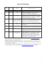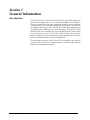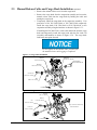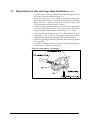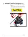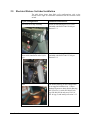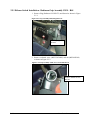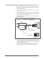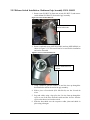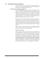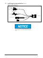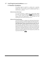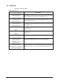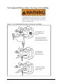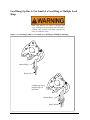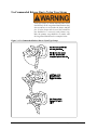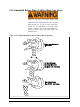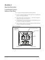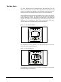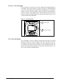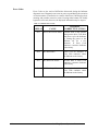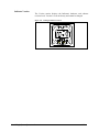
1
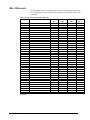
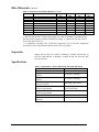
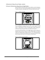
Owner's Manual For the Cargo Hook Suspension System on the Robinson R44 Series Helicopter Kit Part Numbers 200-324-00 200-325-00 200-325-01 200-340-00 Owner's Manual Number 120-137-00 Revision 7 02/27/14 13915 NW 3rd Court Vancouver, Washington 98685 USA Phone: 360-546-3072 Fax: 360-546-3073 Toll Free: 800-275-0883 www.OnboardSystems.com This page intentionally left blank. Record of Revisions Revision Date Page(s) Reason for Revision 0 11/06/07 All Initial Release 1 02/04/09 All Added Load Weigh Kit P/N 200-325-01 and accompanying installation and operation instructions. Re-arranged installation instructions. 2 10/12/09 1-1, 1-2, 5-1 Changed Cargo Hook Service Manual for kit P/N 200324-00 to 122-001-00 (was 122-013-00). Clarified kit applicability in Introduction paragraph. 3 06/11/10 Section 1, 2-1, 2-6, 29, 2-11, 2-21, 2-24, Section 3, 4-8, 4-9 & 4-12 Corrected cargo hook location listed in Table 2.11.1 from 92.2 to 93.9. Replaced Warnings, Cautions and Notes section with Safety Labels sections. Updated safety label format throughout document. 4 07/27/10 1-3, 1-4, 2-1, 2-2 Added new suspension assembly configuration (P/N 232-292-01). 5 03/17/11 1-3 & 5-1 Added External Load Limit 800 Decal P/N 215-11900 to Bill Of Materials. Updated RMA information. 6 11/18/13 2-11 to 2-25 Update pin load cell installation instructions. Updated switch P/N 400-053-00 to P/N 400-059-00 and switch housing P/N 232-063-00 to 232-063-01. 7 02/27/14 1-2, 1-3, 2-1, 2-2, 32, 2-4, 2-6, 2-7 Replaced bolt P/N 290-505-00 with 511-076-00. Loosened tolerances on relay location, moved manual release cable T-handle location .80 inches inboard to provide clearance with a/c structure. Updated Notice for locating T-handle. Current revision levels of all manuals are posted on Onboard Systems Int'l web site at www.onboardsystems.com. Register Your Products for Automatic Notifications Onboard Systems offers a free notification service via fax or email for product alerts and documentation updates. By registering your Onboard Systems products at our website, we will be able to contact you if a service bulletin is issued, or if the documentation is updated. You can choose to receive notices on an immediate, weekly, or monthly schedule via fax, email or both methods. There is no charge for this service. Please visit our website at www.onboardsystems.com/notify.php to get started. ii This page intentionally left blank. CONTENTS Section 1 General Information Introduction, 1-1 Safety Labels, 1-2 Bill of Materials, 1-3 Inspection, 1-4 Specifications, 1-4 Theory of Operation, 1-5 Section 2 Installation Instructions 2.1 Cargo Hook Suspension Assembly Installation, 2-1 2.2 Electrical Release Wiring Installation, 2-3 2.3 Manual Release Cable and Cargo Hook Installation, 2-6 2.4 Electrical Wiring to Cargo Hook, 2-12 2.5 Electrical Release Switches Installation, 2-13 2.6 Optional Left Seat Release Switch Installation, 2-20 2.7 Load Weigh System Installation, 2-21 2.8 Placards, 2-24 2.9 Installation Check-Out, 2-25 2.10 Component Weights, 2-25 2.11 Cargo Hook Location, 2-25 2.12 Paper Work, 2-25 Section 3 Operation Instructions Operating Procedures, 3-1 Optional Flight Configuration, 3-1 Cargo Hook Rigging, 3-2 Un-Commanded Release Due to Too Large of a Load Ring, 3-4 Load Hang-Up Due to Small Load Ring or Multiple Load Rings, 3-5 Un-Commanded Release Due to Nylon Type Straps, 3-6 Un-Commanded Release Due to Cable or Rope Type Straps, 3-7 Contents continued Section 4 Load Weigh System Operation Instructions Indicator Front Panel, 4-1 The Run Mode, 4-2 To Zero or Tare the Display, 4-3 To Un-Zero the Display, 4-3 Error Codes, 4-4 The Setup Mode, 4-5 Indicator Dampening, 4-7 To look at, or change the dampening level, 4-7 Indicator Calibration, 4-8 To look at or change the calibration code, 4-8 Installation Zero, 4-9 To run the installation zero routine, 4-9 Calibration by Lifting a Known Weight, 4-9 To run calibration by known weight routine, 4-10 Setting the Scale on a Remote Analog Meter, 4-11 To look at or change the scale, 4-11 Select KG or LB Units, 4-12 To look at or change the units, 4-12 Indicator Version, 4-13 Section 5 Maintenance Instructions for Returning a System to the Factory, 5-1 Section 6 Certification FAA STC, 6-1 Canadian Approval, 6-3 EASA STC, 6-5 ANAC Approval, 6-8 Section 1 General Information Introduction The P/N 200-324-00, 200-325-00, and 200-325-01 Cargo Hook Suspension System Kits are approved for use on the Robinson R44 series helicopters. These kits include the cargo hook, suspension assembly, internal electrical wiring including release switches, and manual release cable. The 200-32501 includes a load weigh system. The P/N 200-324-00 kit is eligible for use on the R44 model, which has a 14V electrical system. The P/N 200-325-00 and 200-325-01 kits are eligible for use on the R44 Raven II model, which has a 28V electrical system. The P/N 200-325-00 and 200-325-01 kits also include a different cyclic switch housing assembly than the P/N 200-324-00 kit to accommodate the Raven II cyclic configuration. The load weigh system for the P/N 200-325-01 kit includes a pin load cell assembly at the cargo hook, a cockpit mounted C-39 load weigh indicator, and the interconnecting wire harness. General Information 1-1 Safety Labels The following definitions apply to safety labels used in this manual. Indicates a hazardous situation which, if not avoided, will result in death or serious injury. Indicates a hazardous situation which, if not avoided, could result in death or serious injury. Indicates a hazardous situation which, if not avoided, could result in minor or moderate injury. Draws the reader’s attention to important or unusual information not directly related to safety. Used to address practices not related to personal injury. 1-2 General Information Bill of Materials The following items are included with the Cargo Hook Suspension System Kits. If shortages are found contact the company from whom the system was purchased. Table 1-1 Suspension System Bill of Materials Part No. Description 120-137-00 121-051-00 122-001-00 123-030-00 528-010-06 528-010-04 232-292-01 290-505-00* 270-089-00 215-118-00 215-119-00 270-090-00 232-114-01 232-152-01 290-478-01 268-014-01 510-297-00 510-286-00 510-209-00 512-010-00 500-066-00 500-065-00 512-018-00 440-006-00 445-002-00 445-003-00 410-162-00 510-277-00 510-278-00 510-279-00 505-011-00 400-059-00 450-001-00 512-027-00 210-226-01 270-048-04 210-095-00 400-048-00 Owner’s Manual RFM Supplement Cargo Hook Service Manual ICA Maintenance Manual 3,600 Lb. Hook Assembly, 12V 3,600 Lb. Hook Assembly, 28V Suspension Assembly*** Drilled Head Cap Screw Wire Assembly, Circuit Breaker R22/44 Multiple Decal Sheet External Load Limit 800 Decal Wire Harness Switch Housing Assembly Switch Housing Assembly Switch Guard, Co-pilots R44 Manual Release Assembly Screw Nut Washer Adel Clamp Spacer Grommet Edging Clamp Circuit Breaker Relay Relay Ring Terminal Screw Washer Nut Grommet Switch Heat Shrink, ½” Lg. Adel Clamp Pin Load Cell Assembly Load Weigh Internal Harness C-39 Indicator Power Switch 200-324-00 12V 1 1 1 1 1 1 2 1 1 1 1 1 1 1 1 1 1 1 1 1 2 1 1 2 2 2 2 2 1 4 3 - 200-325-00 28V 1 1 1 1 1 1 2 1 1 1 1 1 1 1 1 1 1 1 1 1 2 1 1 2 2 2 2 2 1 4 3 - 200-325-01 28V 1 1 1 1 1 1 2 1 1 1 1 1 1 1 1 1 1 1 1 1 2 1 1 2 2 2 2 2 1 4 3 1 1 1 1 continued General Information 1-3 200-34000** 1 1 1 1 Bill of Materials continued Table 1-1 Suspension System Bill of Materials continued Part No. Description 200-324-00 12V 215-010-00 Placard 215-012-00 Placard 510-028-00 Screw 510-029-00 Nut 510-178-00 Cotter Pin 510-170-00 Nut 510-174-00 Washer 510-183-00 Washer - 200-325-00 28V - 200-325-01 28V 2 1 4 4 - 200-34000** 2 1 4 4 1 1 1 1 *Bolt P/N 511-076-00 superseded P/N 290-505-00. These parts are interchangeable. ** Kit P/N 200-340-00 is a load weigh upgrade kit, which is intended for operators using the 200-325-00 kit and would like to add load weighing. It converts the P/N 200-325-00 kit to a P/N 200-325-01 kit. *** Suspension Assembly P/N 232-292-01 supersedes P/N 232-292-00 Suspension Assembly, P/N 291-108-00 Pillow Block, and P/N 291-107-00 Pin. Inspection Inspect the kit items for evidence of damage, corrosion and security of lock wire and fasteners. If damage is evident, do not use the items until they are repaired. Specifications Table 1.2 Specifications - Kit P/N 200-324-00, 300-324-00, 200-325-01 Design load Design ultimate strength Cargo hook electrical release capacity Cargo hook mechanical release capacity Force required for mechanical release at 3,600 lb. Cargo hook P/N 528-010-04 electrical requirements Cargo hook P/N 528-010-06 electrical requirements Cargo hook minimum release load Cargo hook mating electrical connector 1-4 800 lb. (363 kg.) 3,000 lb. (1,361 kg.) 8,750 lbs. (3,969 kg) 8,750 lbs. (3,969 kg.) 8 lb. Max (.400” travel) 22-32 VDC, 6.9 - 10 amps (P/N 528-029-00) 10-15 VDC, 7.7-11.5 amps 7 pounds PC06P8-2S General Information Theory of Operation The primary elements of the Cargo Hook are the load beam, the internal mechanism, and a DC solenoid. The load beam supports the load and is latched through the internal mechanism. The DC solenoid, an external manual release cable and a manual release lever provide the means for unlatching the load beam. The load is attached to the load beam by passing the cargo sling ring into the throat of the load beam and pushing the ring against the upper portion of the load beam throat, which will initiate the hook to close. In the closed position, a latch engages the load beam and latches it in this position. To release the load, the latch is disengaged from the load beam. With the latch disengaged, the weight of the load causes the load beam to swing to its open position, and the cargo sling slides off the load beam. A load release can be initiated by three different methods. Normal release is achieved by pilot actuation of the push-button switch in the cockpit. When the push-button switch is pressed, it energizes the DC solenoid in the Cargo Hook, and the solenoid opens the latch in the internal mechanism. A secondary release button is also provided on the left seat lower outboard support. In an emergency, release can be achieved by operating a manual release cable. The release cable operates the internal mechanism of the Cargo Hook to unlatch the load beam. The load can also be released by the actuation of a lever located on the side of the Cargo Hook. General Information 1-5 This page intentionally left blank. Section 2 Installation Instructions These procedures are provided for the benefit of experienced aircraft maintenance facilities capable of carrying out the procedures. They must not be attempted by those lacking the necessary expertise. The R44 maintenance and parts manuals should be available throughout the installation as various R44 components will be referred to by name and part number. The part numbers for Robinson components are provided for reference and are subject to change by Robinson. All equipment removed and replaced shall be done in accordance with the R44 maintenance manual. All installed hardware shall be torqued in accordance with standard torques of AC43.13 unless noted otherwise. Apply torque stripe where applicable. 2.1 Cargo Hook Suspension Assembly Installation o o o o Insert the cap screws (P/N 290-505-00 or 511-076-00) into the two holes in the Robinson hardpoint block and screw in to ensure thread integrity. Some re-work of access holes in skin may be required to allow bolt installation. Remove the two cap screws. Apply sealant to the side of the Suspension Assembly (P/N 232-29201) Pillow Block which is to be installed against the belly skin. Orient the Suspension Assembly as shown in Figure 2.1.1 and secure it to the helicopter with the two P/N 290-505-00 or 511-076-00 cap screws (refer to Figure 2.1.1). ** Install the Suspension Assembly so that the engraved “F” is forward and the engraved “A” is aft as shown in Figure 2.1.1. o Torque screws to 26 ft-lbs. o Safety-wire the cap screws to the ears on the pillow block. ** If installing Suspension Assembly P/N 232-292-00, Pillow Block P/N 291-108-00, and Pin P/N 291-107-00 perform the following (the Suspension Assembly P/N can be determined by checking the underside of the Pillow Block, P/N 232-292-01 Suspension Assembly has a “-01” on the underside of the Pillow Block). o Grease the Pin (P/N 291-107-00) with Mobilgrease 28 or equivalent before assembly. o Partially insert the Pin into the Pillow Block. Hold the Suspension Assembly (P/N 232-292-00) in the orientation as shown in Figure 2.1.2, position it within the slot of the Pillow Block, and slide the Pin through the Suspension Assembly and into the other side of the pillow block. Installation Instructions 2-1 2.1 Cargo Hook Suspension Assembly Installation continued Figure 2.1.1 Suspension Assembly Installation – (P/N 232-292-01) Figure 2.1.2 Suspension Assembly Installation – (P/N 232-292-00) 2-2 Installation Instructions 2.2 Electrical Release Wiring Installation The electrical release system is powered from the bus through a 10 amp circuit breaker to a relay in the center tunnel. Switches on the cyclic and co-pilots seat support control the relay and energize the DC solenoid in the Cargo Hook, opening the hook and releasing the cargo. A schematic for the electrical system is shown below in Figure 2.2.1. Figure 2.2.1 Electrical Schematic Optional Left NO Seat Switch P/N 400-059-00 2B C NO 2A 4B Cyclic Switch P/N 400-059-00 C 4A 22G 22G BUS Circuit Breaker 10 amp P/N 440-006-00 16G 5 Airframe ground Connector P/N 410-131-00 (PC06A8-2S(SR)) 4 16G 16G 16G 16G Wire Harness P/N 270-090-00 1 2 3 A A B B Cargo Hook (PC07A-8-2P) 16G 6 Spade Connectors 4 Places Relay P/N 445-002-00 (12V) or P/N 445-003-00 (28V) Installation Instructions 2-3 2.2 Electrical Release Wiring Installation continued o o Install the relay (P/N 445-002-00 if installing kit P/N 200-326-00 or P/N 445-003-00 if installing kit P/N 200-327-00) on the keel panel below the existing relay installation (reference Figure 2.2.2) using the hardware as shown. Place the main wire harness (P/N 270-090-00) into the tunnel on top of the existing wire bundle. Figure 2.2.2 Wire Harness and Relay Installation Circuit Breaker P/N 440-006-00 Use existing available location. Wire Harness P/N 270-090-00 CARGO Existing Relay Wires 2B & 4B to optional left seat switch. A Decal P/N 215-112-00 Grommet P/N 505-011-00 A View Looking Down Relay P/N 445-002-00 or P/N 445-003-00 0.00/2.00 1.75/4.75 2.52 +.04/-.00 B Ø.157 X2 B Nut P/N 510-279-00 Screw P/N 510-277-00 Washer P/N 510-278-00 Relay P/N 445-002-00 or P/N 445-003-00 Section B-B 2 PLCS View A-A Looking Outboard 2-4 o Connect wire numbers 1, 2 and 3 from the main wire harness to the relay terminals A, B and 7 as shown in the electrical system schematic. Connect jumper wire 6 to relay terminal 5. o Connect the ground lead of wire number 5 to any convenient existing ground location in the tunnel. o Secure the wire harness with wire ties as required. Installation Instructions 2.2 Electrical Release Wiring Installation continued Installation Instructions o Remove the circuit breaker cover panel and install the 10 amp circuit breaker (P/N 440-006-00) in an available location. On some early models, it may be necessary to remove the panel and make a hole for the additional circuit breaker. o Open the circuit breaker to disarm the cargo hook release circuit. o Use the wire assembly (P/N 270-089-00) and a ring terminal (P/N 410162-00) as a jumper to power the input side of the circuit breaker in compliance with AC 43.13. o Feed the #1 wire of the main wire bundle from the tunnel into the circuit breaker bay using the existing wire harness access hole. Connect the wire to the output side of the circuit breaker using the other ring terminal (P/N 410-162-00) provided. Secure the power wire to the existing wire harnesses with tie wraps. o The 2A and 4A wires are routed to the cyclic switch, which is installed per Section 2.5. o If the optional co-pilot’s seat switch is to be installed, the 2B and 4B wires are routed to the outboard side of the co-pilot’s seat, otherwise cap and stow these two wires. The co-pilot’s seat switch is installed per section 2.6. o The #3 and #4 electrical wires are to be routed out the same hole in the forward belly panel as the manual release cable. This hole is created during the manual release cable installation (reference section 2.3). 2-5 2.3 Manual Release Cable and Cargo Hook Installation Install the manual release T-handle on the cyclic control cover in the location shown in Figure 2.3.1. If, due to configuration changes by Robinson Helicopters, this location is not available, locate it as near as possible. IMPORTANT: Before proceeding with drilling hole for T-handle, verify there is clearance beneath the cyclic control cover for the release cable to extend down. o Drill a .38 inch (9.6 mm) diameter hole through the left aft corner of the cyclic control cover and box assembly as shown in Figure 2.3.1. o Locate and drill the hole for the cable clamp in the tunnel keel panel as shown. o Make a cutout in the forward belly panel as shown in Figure 2.3.2 and install the P/N 500-065-00 edge grommet. o Remove the T-handle and first nut from the P/N 268-014-01 manual release cable. o Place the 268-014-01 manual release cable inside the tunnel and route the output end of the cable through the cutout in the forward belly panel. Insert the forward end of the cable into the cyclic control cover plate and install the face nut and T-handle as shown in Figure 2.3.1. Install the adel clamp as shown (install on same side as T-handle) and secure the release cable to it. Verify that the release cable does not interfere with push/pull control rods and electrical components in the tunnel and that there is sufficient clearance between these items to allow for motion and account for any slack. o 2-6 Route the #3 and #4 electrical release wires through the cutout and route aft as shown in Figure 2.3.2 and secure them and the manual release cable with adel clamps. Installation Instructions 2.3 Manual Release Cable and Cargo Hook Installation continued Figure 2.3.1 Manual Release Cable Installation CIRCUIT BREAKER PANEL ELT SWITCH Ø.38 A .63/1.00 CARGO RELEASE 1.25±.13 WASHER P/N 510-209-00 KEEL PANEL (REF) A DECAL P/N 215-111-00 ADEL CLAMP P/N 512-010-00 NUT P/N 510-286-00 DECAL P/N 215-110-00 PULL SCREW P/N 510-297-00 CYCLIC CONTROL COVER SPACER P/N 500-066-00 FWD SECTION B-B B BOTTOM SKIN B MANUAL RELEASE CABLE P/N 268-014-01 1.75 2.375 MEASURE FROM FORWARD PANEL OPENING SECTION A-A Installation Instructions 2-7 2.3 Manual Release Cable and Cargo Hook Installation continued Figure 2.3.2 Manual Release Cable Routing 1.20 in. (30 mm) 3.62 in. (92 mm) 1.00 in (25 mm) Grommet P/N 500-065-00 Forward Belly Panel Forward Right Aft Belly Panel View Looking Down Manual Release Cable & Electrical Wiring Adel Clamp (3) P/N 512-027-00 Cargo Hook 2-8 Installation Instructions 2.3 Manual Release Cable and Cargo Hook Installation continued o o o Remove the manual release cover from the cargo hook. Remove the cargo hook from the suspension assembly and screw the manual release cable into the cargo hook by holding the cable and turning the cargo hook. Temporarily install the cargo hook to the suspension assembly. If in possession of kit P/N 200-324-00 or P/N 200-325-00 temporarily install the cargo hook, P/N 528-010-04 or P/N 528-010-06, to the suspension assembly using the hardware as shown in Figure 2.3.3. If installing kit P/N 200-325-01, remove the attach bolt from the cargo hook and temporarily install the cargo hook with the Pin Load Cell Assembly and hardware as shown in Figure 2.3.4. The cargo hook load beam must point forward. Do not tighten nut and install cotter pin until after the manual release cable rigging is completed. Figure 2.3.3 Cargo Hook Installation Washer P/N 510-183-00 Washer P/N 510-174-00 Washer P/N 510-183-00 Attach Bolt P/N 290-332-00 Cotter Pin P/N 510-178-00 Nut P/N 510-170-00 FORWARD Figure 2.3.4 Cargo Hook Installation w/ Pin Load Cell Washer P/N 510-183-00 Nut P/N 510-170-00 Washer P/N 510-174-00 Pin Load Cell Assembly P/N 210-226-01 Cotter Pin P/N 510-178-00 FORWARD Installation Instructions 2-9 2.3 Manual Release Cable and Cargo Hook Installation continued o o o o o o Place the inner cable of the manual release cable through the slot of the release lever fork as shown in Figure 2.3.3. Rotate the release lever in the clockwise direction to remove free play and hold (the free play is removed when the hook lock indicator begins to move). This is also readily felt as the lever rotates easily for several degrees as the free play is removed. Measure the gap between the release lever fork and the cable ball end with the manual release handle in the cockpit in the non-release position. The gap should measure a minimum of .125” (3.2 mm). If the gap does not measure at least .125”, make adjustments at the cargo hook. This is done by removing the cargo hook from the suspension and rotating the cargo hook in the required direction. When correct setting is achieved, tighten the jam nut securely against the cargo hook. Re-install the manual release cover on the cargo hook with the two screws removed. Safety-wire the screws. Figure 2.3.5 Manual Release Cable Rigging 2-10 Installation Instructions 2.3 Manual Release Cable and Cargo Hook Installation continued o o Re-install the washers and nut onto the cargo hook attach bolt or if installing the load weigh system install the washers and nut onto the pin load cell. Tighten nut on cargo hook attach bolt or pin load cell until fully seated, finger tight only. Back off nut to previous castellation, if needed, when aligning cotter pin for installation. Install and secure cotter pin. Do not tighten nut on pin load cell more than finger tight. Overtightening will damage load cell. Figure 2.3.6 Pin Load Cell Tightening Installation Instructions 2-11 2.4 Electrical Wiring to Cargo Hook o Route the electrical release wiring (#3 and #4 wires) with the manual release cable to the cargo hook. o Route (as far as possible) the load cell assembly harness with the manual release cable and electrical release wiring. o Secure the wiring to the manual release cable with ty-wraps at approximately 12” intervals. o Connect the cargo hook electrical release harness connector to the cargo hook. Listed below is the pin out for the cargo hook connector. Safety wire the connector. Table 2.4.1 Cargo Hook Connector Pin Function A Ground B Power The Cargo Hook is equipped with a suppression diode that will be damaged if the Cargo Hook electrical connections are reversed. 2-12 Installation Instructions 2.5 Electrical Release Switches Installation The table below shows three R44 cyclic configurations, refer to the column on the right for installation instructions for the electrical release switch. Cyclic Configuration Installation Instructions R44 with C058 Grip Assembly Install Switch Housing P/N 232-114-01 (included with Kit P/N 200-326-00) per Section 2.5.1. R44 II with C058 Grip Assembly Start switch installed in end of cyclic grip. Install Switch Housing P/N 232-152-01 (included with Kit P/N 200-327-00) per Section 2.5.2. R44 The Switch Housing for this configuration is not supplied with these kits. Contact Onboard Systems to obtain Switch Housing P/N 232-063-01, switch P/N 400-059-00, cap P/N 400-054-00 and screw P/N 510301-00 (qty 2) and install per Section 2.5.3. Installation Instructions 2-13 2.5.1 Release Switch Installation - Robinson Grip Assembly C058 – R44 1. Remove Plug (Robinson P/N DP-875) and discard as shown in Figure 2.5.1. Figure 2.5.1 Grip Assembly C058, Plug Removal Remove plug and discard. 2. Remove outboard screw (MS27039C0806) and nut (MS21042L08) as shown in Figure 2.5.2. Figure 2.5.2 Grip Assembly C058, Screw and Nut Removal Remove outboard screw and nut. 2-14 Installation Instructions 2.5.1 Release Switch Installation - Robinson Grip Assembly C058 – R44 continued 3. Using a lead wire, pull the number 2A and 4A wires from wire harness P/N 270-090-00 up through the horizontal tube and out the end of the grip assembly. 4. Slide a piece of heat shrink (P/N 450-001-00) over the 2A and 4A wires (ref. Figure 2.5.3). 5. Prep and solder, using a lap splice, the 2A wire from up through the cyclic to one of the wires from the switch and the 4A wire from the cyclic to the other wire from the switch. 6. Slide the heat shrink over the respective solder joints and shrink in place using a heat gun. Figure 2.5.3 Grip Assembly C058, Screw and Nut Removal R44 Cyclic Grip Cyclic Switch Housing Assembly P/N 232-114-01 A Heat Shrink, 1/2" Lg. P/N 450-001-00 A Install Placard P/N 215-110-00 here. VIEW A-A 7. Install the Switch Housing Assembly into the end of the grip assembly and secure with the Screw (P/N MS27039C0806) removed earlier. The Nut (P/N MS21042L08) removed earlier will not be re-used for this installation and can be discarded. 8. Check the cyclic for freedom of motion throughout its complete travel range and ensure the wires are not chafing on any components. Installation Instructions 2-15 2.5.2 Release Switch Installation - Robinson Grip Assembly C058 –R44 II 1. Remove nut (P/N B227-4) from start switch (P/N B227-2) and remove switch Mount (P/N D443-2) from end of grip assembly. Figure 2.5.4 Start Switch Removal Remove nut, start switch, and switch mount. 2. Remove outboard screw (MS27039C0806) and nut (MS21042L08) as shown in Figure 2.5.5. The nut will not be re-used for this installation and can be discarded. Figure 2.5.5 Screw and Nut Removal Remove outboard screw and nut. 3. Using a lead wire, pull the number 2A and 4A wires up through the horizontal tube and out the end of the grip assembly. 4. Slide a piece of heat shrink (P/N 450-001-00) over the 2A and 4A wires. 5. Prep and solder, using a lap splice, the 2A wire from up through the cyclic to one of the wires from the switch and the 4A wire from the cyclic to the other wire from the switch. 6. Slide the heat shrink over the respective solder joints and shrink in place using a heat gun. 2-16 Installation Instructions 2.5.2 Release Switch Installation - Robinson Grip Assembly C058 –R44 II continued Figure 2.5.6 Release Switch Installation R44 Cyclic Grip Cyclic Switch Housing Assembly P/N 232-152-01 A Heat Shrink, 1/2" Lg. P/N 450-001-00 A Install Placard P/N 215-110-00 here. VIEW A-A 7. Insert the Switch Housing Assembly into the end of the C058 cyclic grip while pulling the Robinson start switch through it. Re-install the Robinson start switch into the Switch Mount (P/N D443-2) with the nut and secure the Switch Mount by tightening the pre-installed set screw in the Switch Housing. 8. If necessary, while inserting the Switch Housing Assembly into the cyclic grip, pull excess wire back down the cyclic grip. Secure the Switch Housing Assembly into the end of the grip assembly with the MS27039C0806 screw removed earlier. Figure 2.5.7 Switch Housing Assembly Installed 9. Install placard P/N 215-110-00 as shown in Figure 2.5.6. 10. Check the cyclic for freedom of motion throughout its complete travel range and ensure the wires are not chafing on any components. Installation Instructions 2-17 2.5.3 Cyclic Release Switch Installation 1. Remove the cover to the cyclic switch housing and ensure its wires are clear of the areas to be drilled on the horizontal cyclic control handle. 2. Drill a .172 inch (4.4 mm) diameter hole on the forward side of the cyclic grip as shown in Figure 2.5.8. 3. Use a lead wire and route the number 2A and 4A wires up through the cyclic stick and out the existing wire routing hole. Place a length of heat shrink over the wires that will cover the exposed portion similar to the existing com wires. 4. Using a lead wire again, pull the number 2A and 4A wires up through the cyclic grip and out the .250 hole on the front of the cyclic grip. 5. Place a 1 inch (25.4 mm) length of heat shrink over each wire to the cyclic switch. Prepare each wire end and solder them to the normally open and closed switch terminals as shown in the Figure 2.2.1 wiring schematic. Using a heat gun, shrink the covering material to final size. Figure 2.5.8 Cyclic Switch Wire Routing .50 Existing holes Cyclic (REF) Ø.172 (Drilled in step #2) Looking Aft 6. Install the 400-059-00 switch in the 232-063-01 cyclic switch housing assembly using needle nose pliers to hold the switch. Install the completed switch housing assembly with the hardware as shown in Figure 2.5.9. Remove the existing switch housing screws and replace them with the longer 510-301-00 screws and retain one of the removed nuts as shown in Figure 2.5.9. 2-18 Installation Instructions 2.5.3 Cyclic Release Switch Installation, continued 7. Re-install the com switch housing and wires. 8. Check the cyclic for freedom of motion throughout its complete travel range and ensure the wires are not chafing on any components. Figure 2.5.9 Cyclic Release Switch Installation Switch P/N 400-059-00 Switch Housing Assembly P/N 232-063-01 Retain Nut CARGO RELEASE Decal P/N 215-110-00 Screw P/N 510-301-00 (2 PLCS) Installation Instructions 2-19 2.6 Optional Left Seat Release Switch Installation If the left seat release switch installation is not desired, cap and stow wires 2B and 4B per AC 43.13 and skip this section. 1. Drill a .250 inch hole in the left side of the tunnel wall above the main wire bundle in a convenient location or use an existing unused hole in the tunnel wall. Install Grommet (P/N 505-011-00). 2. Drill a .50 inch hole in the outboard side of the left seat support as shown in Figure 2.6.1. 3. Route the number 2B and 4B wires through the grommeted hole and through the left baggage area to the .50 inch hole on the outboard seat support. Secure the wires to the forward seat hinge fasteners with two clamps (P/N 512-018-00). 4. Slide the nut (provided with the switch P/N 400-059-00) over the wires from inside the seat support and feed the wires through the .50 inch hole and through the switch guard (P/N 290-478-01). 5. Place a .50 inch length of heat shrink over each wire to the switch. Solder the wires to the switch as shown in the Figure 2.2.1 wiring schematic. Use a heat gun and shrink the covering material to final size. Place the switch (P/N 400-059-00) into the switch guard and through the seat as shown in Figure 2.6.1 and secure with nut. Figure 2.6.1 Left Seat Release Switch Installation Switch Guard P/N 290-478-01 LEFT SEAT 1.00 in. (25.4 mm) A Drill .50 in. (12.7 mm) hole in seat support. Switch P/N 400-059-00 SECTION A - A 2-20 1.60 in. 41 mm A CARGO RELEASE Placard P/N 215-110-00 Installation Instructions 2.7 Load Weigh System Installation Kit P/N 200-327-01 features a load weigh system, which includes the load cell, an electrical wiring internal harness and a C-39 load weigh indicator. If this kit is not being installed, skip to section 2.8. Load Weigh Internal Harness Installation The Load Weigh Harness is made up of four cables terminated to one connector. The connector is plugged into the back of the Indicator. One of the cables is marked “LOAD CELL” and is fitted with a bulkhead fitting. This cable is connected to the load cell. Another cable is marked “POWER” and is connected to the aircraft electrical power. Another cable is marked “LIGHT”, refer to the Indicator Internal Back Light section for installation instructions. The last cable is marked “DATA” and is connected to an optional Data Recorder and C-23 printer. The load cell cable can be routed with the hook electrical release harness to the cargo hook area. The load cell connector should be mounted in a location close enough to the load cell to ensure the load cell cable is not strained when the cargo hook is moved to its furthermost point, but far enough away to minimize excess cable which may be snagged. Secure the connector with the screws (P/N 510-028-00) and nuts (P/N 510-029-00) provided. Route the harness to the electrical bus and to the Indicator mounting location. Secure the cables to the existing wiring bundles with the tywraps. Secure the cables clear of flight control rods. Electrical Connections Install the supplied power switch, P/N 400-048-00. The “POWER” cable on the Internal Harness is supplied extra long, cut off the excess cable and use as needed to connect the switch and circuit breaker. Connect the “POWER” white wire (red if wire harness P/N 270-048-00 is installed) to one side of the power switch, connect another piece of suitable wire to the other side of the switch and then to an available 1 or 2 amp circuit breaker as illustrated in Figure 2.7.1. Connect the circuit breaker to the 28 VDC bus. Connect the white/blue wire (black if wire harness P/N 270-048-00 is installed) to the ground bus. The cable shield wire is not grounded at this end of the cable and may be cut off. Use a minimum of 22 gauge wire to make all connections. Secure the connections and protect from corrosion. Installation Instructions 2-21 2.7 Load Weigh System Installation continued Figure 2.7.1 Wiring Arrangement Power switch (supplied) 1 amp circuit breaker (operator supplied) White (Red) To 28 VDC To airframe ground White/Blue (Black) Power cable Back light potentiometer (operator supplied) To 28 VDC White (Clear) To airframe ground Light cable White/Blue (Black) To C-39 indicator Data Recorder Cable To optional equipment To load cell If a C-23 Printer is being utilized with a C-30 Data Recorder, a 5 amp circuit breaker should be used. 2-22 Installation Instructions 2.7 Load Weigh System Installation continued C-39 Indicator Installation The indicator should be mounted in a position that is convenient, accessible and visible to the pilot. It can be mounted in a standard 2¼" instrument hole. Connect the Indicator to its Internal Harness, refer to Internal Harness Installation. Indicator Internal Back Light The 210-095-00 Indicator is equipped with an Internal Back Lighting System that can be connected to the aircraft 28 VDC light dimming circuit. Use a 22 gauge, twisted pair, shielded cable to connect the aircraft dimming circuit to the Internal Harness. The cable shield wire is not grounded at this end of the cable and may be cut off. Indicator Hook-Open Warning The 210-095-00 Indicator is equipped with a Hook-Open Warning feature that can be connected to a cargo hook equipped with a hook open switch. Depending on the capabilities of the cargo hook switch, the Indicator will flash "HOOK OPEN" when the cargo hook load beam is open. The cargo hook switch must be normally open when the cargo hook load beam is in the closed position. When the load beam is open, one side of the switch must be grounded and the other side of the switch is to be connected to the Indicator. Use a 22 gauge, shielded wire to connect the cargo hook switch to the Indicator. Disassemble the Indicator mating connector and carefully solder the wire, from the cargo hook switch, to pin H. Connect the cable shield wire to airframe ground as close to the cargo hook as possible, at the cargo hook end of the cable ONLY. Installation Instructions 2-23 2.8 Placards Install the following placards. Table 2.8.1 Placards DECAL NUMBER (DECAL DESCRIPTION) LOCATION P/N 215-110-00 Mount adjacent to the cyclic release switch in clear view of the pilot (see Figure 2.5.3, Figure 2.5.6, or Figure 2.5.9). (CARGO RELEASE) P/N 215-110-00 (CARGO RELEASE) P/N 215-110-00 (CARGO RELEASE) P/N 215-111-00 (PULL) P/N 215-112-00 (CARGO) P/N 215-114-00 (CLASS B ROTORCRAFT..) P/N 215-115-00 (FAR PART 133.35(A) OPERATIONS ...) P/N 215-119-00 (EXTERNAL LOAD LIMIT = 800 LBS (363 KGS)) 2-24 Mount adjacent to the left seat release switch in clear view of the pilot (See Figure 2.6.1). Mount adjacent to the manual release in clear view of the pilot. (See Figure 2.3.1) Mount adjacent to the manual release in clear view of the pilot. (See Figure 2.3.1) Mount adjacent to the cargo hook circuit breaker in clear view of the pilot. Mount on the instrument panel in clear view of the pilot. Mount on the instrument panel in clear view of the pilot. Mount on the belly of the aircraft adjacent to the cargo hook attachment point in clear view of the ground support personnel. Installation Instructions 2.9 Installation Check-out After installation of the Cargo Hook Suspension System, perform the following functional checks. 1. Swing the installed Cargo Hook to ensure that the manual release cable assembly and the electrical release cable have enough slack to allow full swing of the suspension assembly without straining or damaging the cables. The cables must not be the stops that prevent the Cargo Hook from swinging freely in all directions. 2. Apply 10-20 pounds (4.5 - 9 kg) to the cargo hook load beam and pull the handle operated cargo hook manual release, the Cargo Hook must release the load. 3. Close the cargo hook release circuit breaker and position the battery switch to the ON position. With no load on the cargo hook load beam, depress the cargo hook electrical release buttons, the Cargo Hook should release using the cyclic and left seat electrical release switches. Reset the cargo hook load beam. 2.10 Component Weights The weight of the system is listed in Table 2.10.1. Table 2.10.1 Component Weights Item Weight lbs (kgs) P/N 200-324-00 5.3 (2.4) P/N 200-325-00 5.3 (2.4) P/N 200-325-01 6.8 (3.1) 2.11 Cargo Hook Location Table 2.11.1 Cargo Hook Location Fuselage Station 93.9 2.12 Paper Work In the US, fill in FAA form 337 for the initial installation. This procedure may vary in different countries. Make the appropriate aircraft log book entry. Insert the Rotorcraft Flight Manual Supplement 121-051-00 in the Rotorcraft Flight Manual. Installation Instructions 2-25 This page intentionally left blank. Section 3 Operation Instructions Operating Procedures Prior to each job perform the following: 1. Ensure that the Cargo Hook has been properly installed and that the manual and electrical release cables do not limit the movement of the hook. 2. Be completely familiar with this manual, particularly the Cargo Hook rigging section. 3. Be completely familiar with all Cargo Hook operating instructions. 4. Activate the electrical system and press the cargo hook release button to ensure the cargo hook electrical release is operating correctly. The Cargo Hook should re-latch after release. If the hook does not re-latch do not use the unit until the difficulty is resolved. The release solenoid is intended to be energized only intermittently. Depressing the electrical release button continuously in excess of 20 seconds may cause the release solenoid to overheat, possibly causing permanent damage 5. Activate the manual release lever to test the cargo hook manual release mechanism. The mechanism should operate smoothly and the Cargo Hook must re-latch after release. If the hook does not re-latch do not use the unit until the difficulty is resolved. Operation Instructions 3-1 Optional Flight Configuration The aircraft can be operated with the Cargo Hook and gimbal assembly removed. This may be accomplished by removing the Cargo Hook from the 232-292-00 Suspension Assembly. Then remove 291-108-00 Pillow Block and 232-292-00 Suspension System together by removing the two Pillow Block mounting fasteners (See Figure 2.1.1). Secure the manual release cable and electrical wire bundle to any convenient location on the frame structure using tie wraps. Cargo Hook Rigging Extreme care must be exercised in rigging a load to the Cargo Hook. If the load ring is too big it may work its way around the end of the load beam and be supported for a time on the keeper and then fall free. If the load ring is too small it may jam itself against the load beam during an attempted release. The following illustrations show recommended configurations and potential difficulties that must be avoided. The examples shown are not intended to represent all problem possibilities. It is the responsibility of the operator to assure the hook will function properly with the rigging. 3-2 Operation Instructions Cargo Hook Rigging, continued Figure 3.1 Examples of Correct and Incorrect Cargo Hook Rigging Correct Rigging .875 inch (22.2 mm) max. cross section 1.50/1.87 inch Primary (38.1/47.5 mm) Ring ID .625 inch (15.9 mm) max. cross section Incorrect Rigging Operation Instructions Load Incorrect Rigging 3-3 Un-Commanded Release Due to Too Large of a Load Ring Load rings that are too large will cause an uncommanded release. The ring will flip over the end of the load beam and flip the keeper up and then fall free. Only correctly sized load rings must be used. See examples below. Figure 3.2 Un-Commanded Release Due to Too Large of a Load Ring Load Ring flips over the Load Beam and gyrates. The flip over often occurs with long line operations during landings and take offs. Load Ring moves inward and bears against the keeper The Keeper is forced to rotate allowing the Ring to slip off 3-4 Operation Instructions Load Hang-Up Due to Too Small of a Load Ring or Multiple Load Rings Load rings that are too small or multiple load rings will hang on the load beam when the load is released. Only correctly sized load rings must be used. See examples below. Figure 3.3 Load Hang-Up Due to Too Small of a Load Ring or Multiple Load Rings Jammed Ring Sling Load Load hang-up due to multiple rings on load beam Jammed Rings Sling Load Operation Instructions 3-5 Un-Commanded Release Due to Nylon Type Straps Nylon type straps (or similar material) must not be used directly on the cargo hook load beam as they have a tendency to creep under the keeper and fall free. If nylon straps must be used they should be first attached to a correctly sized primary ring. Only the primary ring should be in contact with the cargo hook load beam. See examples below. Figure 3.4 Un-Commanded Release Due to Nylon Type Straps 3-6 Operation Instructions Un-Commanded Release Due to Cable or Rope Type Straps Cable or rope type straps must not be used directly on the cargo hook load beam. Their braided eyes will work around the end of the load beam and fall free. If cable or rope is used they should be first attached to a correctly sized primary ring. Only the primary ring should be in contact with the cargo hook load beam. See examples below. Figure 3.5 Un-Commanded Release Due to Cable or Rope Type Straps Maintenance 3-7 This page intentionally left blank. Section 4 Operation Instructions Load Weigh System Indicator Front Panel The C-39 Indicator front panel includes the following features. The four 7 segment LCD digits show the weight on the Cargo Hook and displays various Setup information. The Legends clarify the digital display. i.e. when the LB Legend is turned on, the display will be pounds, etc. The Right button is used to Zero the display in the Run Mode and select the digit to be changed in the Setup Mode. The Left button is used to Un-Zero the display in the Run Mode and scroll the selected digit in the Setup Mode. Figure 4-1 Front Panel Calibration & Dampening Legend Zero & Un-Zero Legend Unit Legend Digits Left Button Load Weigh System Operation Instructions Right Button 4-1 The Run Mode The C-39 Indicator has two operating modes, Run and Setup. The Run Mode is used to display the cargo hook weight and the Setup Mode is used to setup or configure the Indicator to the helicopter and to the Load Cell. When powered up, the Indicator always comes to life in the Run Mode. After the Indicator has been correctly installed, power it up by activating the Load Weigh Circuit Breaker. The Indicator will go through a self-diagnostic routine. During this routine the display will display all of the digits and legends. If a problem is found during the routine an Error Code will be displayed. For an explanation of Error Codes see the section Error Codes. After the diagnostic routine the display should look like this: Figure 4-2 After Diagnostic Routine The illustration is of the Indicator in the Run Mode with no load on the hook. Note the LB legend displayed. Figure 4-3 LB Legend Displayed The illustration is a typical hook load reading. The display is 3,500 pounds, note the last digit is not displayed. 4-2 Load Weigh System Operation Instructions To Zero or Tare the Display The zero feature is used to zero or tare the weight on the Cargo Hook that is not wanted, such as the weight of a cargo net or long line. The Right button is used to zero the Indicator reading. When the Right button is pressed the display is zeroed. The zero legend is turned on and the zeroed number is stored in memory. If the Right button is pressed again, before the Un-zero button is pressed, the display blinks in response to the button closure. Zero is only available in the Run Mode. Figure 4-4 Zeroing the Display Zero Legend Un-Zero Legend To Un-Zero the Display The Left button is used to add the zeroed value back into the current Indicator reading or Un-zero the display. When the Left button is pressed, the number previously zeroed is added to the current display and the Unzero legend is turned on. If the Left button is again pressed before the zero button is pressed, the display blinks in response to the button closure. UnZero is only available in the Run Mode. Load Weigh System Operation Instructions 4-3 Error Codes Error Codes are the result of difficulties discovered during the Indicator diagnostic tests. Diagnostic tests occur at power up and during the execution of certain routines. Listed below is a matrix of the Error Code displays, their meaning and possible corrective action. Pressing either button will usually bypass the error code, however, the displayed information may be suspect. Table 4-1 Indicator Error Codes DISPLAY 4-4 CAUSE POSSIBLE CORRECTIVE ACTION Err 1 A/D or D/A circuit failure Potential short in the optional analog meter cable. Clear short and power cycle the Indicator by turning the power to the Indicator off for a few moments. If Error Code continues, return the Indicator to the factory. Err 2 NV Ram failure Power cycle the Indicator; if Error Code continues, return the Indicator to the factory. Err 3 NV Ram write failure Re-enter data, if Error Code continues, return the Indicator to the factory. Err 4 NV Ram busy failure Power cycle the Indicator, if Error Code continues return the Indicator to the factory. Load Weigh System Operation Instructions The Setup Mode The C-39 Indicator can be used with a wide range of helicopters and load cells. The Setup Mode on the Indicator matches the Indicator to the Load Cell and to the helicopter. This is done by entering data into the Indicator. Entered data includes the load cell Calibration Code, the units that the Indicator should read-out (pounds or kilograms), and several other items. The Indicator has a group of Setup routines, arranged in menu form, that are used to configure the Indicator. Shown on the next page is a matrix of the Setup routines and a brief discussion of their function and how they are programmed. A complete discussion of each setup item is presented later in this section. To enter the Setup Mode press both the Right and Left buttons at the same time while the Indicator is powered up and in the Run Mode. To exit the Setup Mode and return to the Run Mode, press both the buttons at the same time. If you are in a Setup routine and have started to change an entry, but you change your mind before completing the procedure, power cycle the Indicator to exit the Setup Mode and then go to the Run Mode without changing the item. The Indicator is power cycled by turning the Indicator power off for a few moments. Load Weigh System Operation Instructions 4-5 The Setup Mode continued Table 4-2 Indicator Setup Routines FUNCTION DISPLAY Press the Left button to scroll through the menu MENU Press the Right button to view or change the menu item. To return to the Run Mode press both the Right and Left buttons at the same time. DAMP Dampening Level, sets the pilots preference for display dampening. CODE Calibration Code, matches the Indicator to the Load Cell. Blinking display is previously entered Dampening Level. Select the desired dampening level by pressing the Left button. Display is previously entered CAL Code. The Code is changed by selecting the digit to be changed with the Right button. The selected digit will blink. Change the blinking digit by pressing the Left button. Display is a combination of load on the Load Cell, and normal load cell zero offset. Remove all weight from the installed Load Cell except the Cargo Hook, and press any button to complete the procedure and return to the Run Mode. No previous display is shown. Enter the known load using the Right button to select the digit to be changed and Left button to enter the number. Known load is entered "X 10" i.e.; 5000 kilograms is entered as 500. After the known load is entered, press both buttons at the same time and lift the known load. When the load is stabilized press either button. A new Calibration Code will be calculated and the known load will be displayed. This completes the procedure. Display is previously entered number. To change the number use the Right button to select a digit, use the Left button to scroll the digit to the desired number. Entry is times 10. Display is previously selected unit. To change the unit, use the Left button. 0 in LOAD Load, is used to calibrate the system by lifting a known load. Scale Scale, matches the analog output of the Indicator to an optional remote analog meter. LB KG XX - V 4-6 Installation ZERO, matches the Indicator to the installed Load Cell and to the helicopter. After this procedure the display will be zero when no load is on the Cargo Hook. Units, selects the Indicator units (pounds or kilograms). Version, is the revision level of the Indicator hardware and software. Version is for information only, it cannot be changed. Load Weigh System Operation Instructions Indicator Dampening The Damp or dampening routine allows the pilot to adjust the Indicator dampening level to his preference. The dampening routine is a program that stabilizes the Indicator reading. It offers a trade-off between Indicator responsiveness and stability. Ten dampening levels are available, from 0 through 9. At level 0 the display responds to the slightest change in weight. However, if the load bounced even slightly, the display digits would respond instantly, making the display look unstable. With a dampening level of 9, the display would be stable under the most turbulent conditions, however, it would take several seconds for the display to respond to a change in weight. The ideal dampening level will depend on the flying conditions. A mid range setting of 5 or 6 is usually adequate. To Look at or Change the Dampening Level With the Indicator powered up and in the Run Mode, press both buttons at the same time to go to Setup. Scroll through the menu, using the Left button, until the word DAMP is displayed. To look at or change the Dampening Level press the Right button. The display should look like this: Figure 4-5 Changing Dampening Level The CAL and the DAMP legend is turned on and the previously set dampening level is displayed. To return to Run without changing the current dampening level press both the Right and Left buttons at the same time. To change the dampening number, use the Left button to scroll the blinking digit to the desired number. After the selection has been made press both the Right and Left buttons at the same time to return to Run. Indicator Calibration The Calibration Code, or CAL code, is a mandatory input. The Indicator will not accurately display the load without the correct Calibration Code. The Calibration Code scales the signal from the Load Cell. If the C-39 Indicator was supplied as part of a Load Weigh System, the Calibration Code will have been entered into the Indicator by the factory, however, it should be confirmed. If the Indicator is to be mated to a different Load Cell, it must be calibrated before use. Calibration can be done by entering a known Calibration Code or by lifting a known load and having the Indicator calibrate itself. Both options are discussed below. Load Weigh System Operation Instructions 4-7 To Look at or Change the Calibration Code With the Indicator powered up and in the Run Mode, press both buttons at the same time to go to Setup. Scroll through the menu until the word CODE is displayed, then press the Right button. The display should look like this: Figure 4-6 Changing the CAL Code The CAL legend is turned on and the previously entered or computed Calibration Code is displayed. To return to Run without changing the CAL Code, press both the Right and Left buttons at the same time. To change the Calibration Code, use the Right button to select the digit to be changed, then use the Left button to scroll the blinking digit to the desired number. When the Calibration Code has been entered, press both the Right and Left button at the same time to return to Run. Depending on the type of Load Cell, the Calibration code could be a 3 or 4 digit number. If the Calibration Code is a 3 digit number a leading zero (0) must be used. For example if a Load Cell had a CAL Code of 395 it would be entered as 0395. If the load cell Calibration Code is not known or as a cross check, the Indicator can generate the Calibration Code. This is done by entering the weight of a known load into the Indicator LOAD routine and then lifting the load. See the section Calibration by Lifting a Known Load. 4-8 Load Weigh System Operation Instructions Installation Zero Installation zero is a routine that matches the Indicator to the INSTALLED Load Cell. It adjusts the Indicator reading to compensate for the weight of the Cargo Hook on the Load Cell and whatever zero offset is built into the Load Cell. The Installation Zero procedure is not mandatory. If done the Indicator will read zero when the Un-Zero button is pressed and there is no weight on the Cargo Hook. If the Installation Zero is not done, the Indicator will show the weight of the Cargo Hook plus the value of the Load Cell zero offset. To Run the Installation Zero Routine With the Indicator powered up and in the Run Mode, press both buttons at the same time to go to Setup. Scroll through the menu until the symbol "0 in" is displayed, then press the Right button. The CAL legend will be turned on and the current weight on the Cargo Hook will be displayed and blinking. Remove any weight that is not to be zeroed out and press either button to complete the procedure and return to the Run Mode. Calibration by Lifting a Known Weight Calibration by lifting a known weight is a Setup routine that calculates the Calibration Code for the Load Cell attached to the Indicator. It is useful if the load cell Calibration Code is not known or as a cross check to the accuracy of a known Calibration Code. The procedure is done by entering the known weight into the Indicator and then lifting the weight. This procedure can be done in the shop or on the helicopter. The accuracy of the procedure is directly related to the weight of the known load. If for example the procedure was done with a 1,000 pound load that was assumed to weigh only 900 pounds, all subsequent lifts would be displayed 10% light. Be sure to include the weight of everything between the Cargo Hook and the load, i.e. the cable, net, dirt, etc. The closer the known load approaches the lifting capacity of the helicopter, the more accurate the calculated Calibration Code will be. Load Weigh System Operation Instructions 4-9 Calibration by Lifting a Known Weight, continued To Run the Calibration by Lifting a Known Weight Routine With the Indicator powered up and in the Run Mode, press both buttons at the same time to go to Setup. Scroll through the menu until the word LOAD is displayed, then press the Right button. The display should look like this: Figure 4-7 Running CAL Routine The CAL legend is turned on and the first digit is blinking. The previous load is not displayed. At this point if you wish to return to the Run Mode without changing the Calibration Code, power cycle the Indicator. At this point it is not possible to return to the Run Mode without changing the Calibration Code by using the buttons on the Indicator front panel. To proceed with the procedure, use the Right button to select the digit to be changed, then use the Left button to scroll the blinking digit to the desired number. Note that the known weight is entered "X 10"; a 1000 pound load is entered as 100. When the known load has been entered, press both the Right and Left button at the same time. The display will look like this: Figure 4-8 Entering Load in CAL Routine 4-10 Load Weigh System Operation Instructions Calibration by Lifting a Known Weight continued The CAL legend and the digits will be blinking. Again, at this point if you wish to return to the Run Mode without changing the Calibration Code, power cycle the Indicator. It is not possible to return to the Run Mode by using the buttons on the Indicator front panel without changing the Calibration Code. If you wish to proceed, lift the known load and when it is stabilized, press either button to complete the procedure. The Indicator will display the load. This ends the procedure. The Indicator is now calibrated to the Load Cell. It is a good practice to go to the Code routine and record the new Calibration code for later reference. Setting the Scale for a remote analog meter The Scale routine is used when a user supplied analog meter is connected to the Indicator. It is used to match or calibrate the analog meter to the Indicator. The Indicator outputs a 0 to 5 VDC analog signal which is proportional to the Load Cell load. The Scale number tells the Indicator at what point in pounds or kilograms it should reach the 5 VDC output. If for example a 5 volt analog meter is used and its full scale reading is 10,000 pounds, the number entered into the Indicator Scale routine would be 1000 (the number is entered X 10). This number tells the Indicator that it should output the proportional 0 to 5 VDC signal between zero pounds and 10,000 pounds. The Scale number does not affect Onboard Slave Meters, P/N 210-106-00 or 210-180-00. This number only affects user supplied instruments connected to the analog out signal. To Look at or Change the Scale With the Indicator powered up and in the Run Mode, press both buttons at the same time to go to Setup. Scroll through the menu until the word SCALE is displayed, then press the Right button. The display should look like this: Figure 4-9 Changing the Scale Load Weigh System Operation Instructions 4-11 To Look at or Change the Scale continued The CAL legend is turned on and the previously set Scale number is displayed. To return to Run without changing the Scale, press both the Right and Left button at the same time. To change the Scale number, use the Right button to select a digit to be changed, then use the Left button to scroll the blinking digit to the desired number. When the complete Scale number has been entered, press both the Right and Left button at the same time to return to Run. Select KG or LB Units The units routine sets the display to read in pounds (LB) or kilograms (KG). To look at or change the Units With the Indicator powered up and in the Run Mode, press both buttons at the same time to go to Setup. Scroll through the menu until the word LB or KG is displayed, then press the Right button. The display should look like this: Figure 4-10 Changing the Units The CAL legend is turned on and the previously set unit is displayed. To return to Run without changing the units, press both the Right and Left button at the same time. To change the units press the Left button. When the selection has been made, press both the Right and Left button at the same time to return to Run. The selected units are displayed when in the Run Mode. 4-12 Load Weigh System Operation Instructions Indicator Version The Version routine displays the Indicator's hardware and software revision levels. Version is set at the factory and cannot be changed. Figure 4-11 Looking at Indicator Version Load Weigh System Operation Instructions 4-13 This page intentionally left blank. Section 5 Maintenance Refer to the Instructions for Continued Airworthiness (ICA) manual 123030-00 for maintenance of the cargo hook suspension system. For maintenance of cargo hook P/N 528-010-04 and P/N 528-010-06 refer to Cargo Hook Service Manual 122-001-00. In Instructions for Returning Equipment to the Factory If an Onboard Systems product must be returned to the factory for any reason (including returns, service, repairs, overhaul, etc) obtain an RMA number before shipping your return. An RMA number is required for all equipment returns. To obtain an RMA, please use one of the listed methods. Contact Technical Support by phone or e-mail ([email protected]). Generate an RMA number at our website: http://www.onboardsystems.com/rma.php After you have obtained the RMA number, please be sure to: Package the component carefully to ensure safe transit. Write the RMA number on the outside of the box or on the mailing label. Include the RMA number and reason for the return on your purchase or work order. Include your name, address, phone and fax number and email (as applicable). Return the components freight, cartage, insurance and customs prepaid to: Onboard Systems 13915 NW 3rd Court Vancouver, Washington 98685 USA Phone: 360-546-3072 Maintenance 5-1 This page intentionally left blank. Section 6 Certification FAA STC Certification 6-1 FAA STC continued 6-2 Certification Canadian Approval Certification 6-3 This page intentionally left blank. 6-4 Certification EASA Approval Certification 6-5 EASA Approval continued 6-6 Certification EASA Approval continued Certification 6-7 ANAC Approval 6-8 Certification ANAC Approval continued Certification 6-9 ANAC Approval continued 6-10 Certification