1
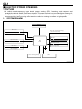
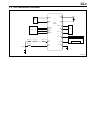
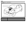
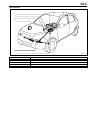
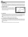
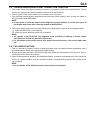
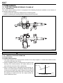
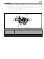
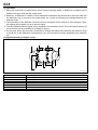
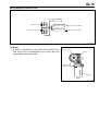
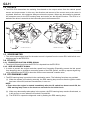
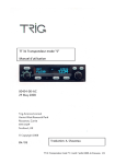
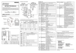
G2 POWER STEERING ELECTRIC POWER STEERING----------- G21 OUTLINE------------------------------ G21 SYSTEM DRAWING --------------- G21 SYSTEM WIRING DIAGRAM ------ G22 LOCATION OF COMPONENTS---- G23 CONTROL ---------------------------- G25 BASIC THEORY-------------------- G25 ASSIST CONTOL ------------------ G25 DIAGNOSIS------------------------ G25 TEST MODE FUNCTION(SENSOR CHECK FUNCTION)--------------- G25 TORQUE SENSOR ZERO-POINT CORRECTION FUNCTION -------- G26 FAIL-SAFE FUNCTION------------ G26 COMPONENTS ----------------------- G27 ELECTRIC POWER STEERING COLUMN AY----------------------- G27 EPS ECU -------------------------- G211 SPEEDOMETER ------------------ G211 EFI ECU -------------------------- G211 EPS WARNING LAMP ------------ G211 G2-1 ELECTRIC POWER STEERING 1 OUTLINE 1. A vehicle speed-responding type electric power steering (EPS), featuring good response and straight-line vehicle stability, has been adopted. This power steering can provide a lighter steering effort while the steering wheel is turned when the vehicle is stationary or is running at low speeds, and an appropriately heavy steering effort when the vehicle is running at medium or high speeds. 1-1 SYSTEM DRAWING Battery Power supply EFI ECU Electric power steering column assembly Engine revolution speed signal Idle-up request signal Motor Speedometer Vehicle speed signal Steering assist force EPS ECU Torque sensor Magnitude and direction of steering torque IG switch IG ON signal EPS warning lamp DLC A21C1232ES23 G2-2 1-2 SYSTEM WIRING DIAGRAM Motor M1 B1 C8 IDUP EFI ECU C12 REV EPS ECU M2 B2 ECU(T C4 D6 TRQV D5 TRQ1 Torque sensor SIO C2 D8 TRQG EPS(TS C11 EPS(W C9 AM1 F/L IG SW DLC D7 TRQ2 EPS warning lamp ECU IG1 C6 IG SPD C5 Speedometer Combination meter EPS F/L A1 PIG PGND A2 MAIN1 F13C6817ES23 G2-3 1-3 LOCATION OF COMPONENTS RHD vehicles e f a d b c J13C1004S23 a b c d e f Steering column Steering gear DLC EPS ECU EFI ECU Combination meter (EPS warning lamp, Speedometer) G2-4 LHD vehicles f a d e b c J13C1005S23 a b c d e f Steering column Steering gear DLC EPS ECU EFI ECU Combination meter (EPS warning lamp, Speedometer) G2-5 2 CONTROL 2-1 BASIC THEORY 1. The power steering is controled by the following method. The motor, installed at the center of the steering column, drives the steering shaft. The steering effort is assisted by transmitting this driving force to the steering rack. Furthermore, the EPS ECU controls the assisting direction and assisting force to optimum values, based on the vehicle speed signals sent from the vehicle speed sensors, torque sensors, and EFI ECU. 2-2 ASSIST CONTOL Vehicle speed Low-speed Motor output current 1. The EPS ECU calculates an optimum assisting force each time, based on the vehicle speed signal from the vehicle speed sensors, steering force and steering direction from the torque sensors. In this way, the output signal to the motor is controlled. 0 Medium-speed High-speed Steering torque L16C1016ET10 2-3 DIAGNOSIS 1. Diagnostics, meaning failure diagnosis, is a function by which if there are any abnormalities in the input/output signal system the ECU will inform a mechanic/technician. If any abnormalities occur, the ECU memorizes the abnormality items, In addition, since the abnormality items remain memorized even when the power supply is lost, for they are written in the nonvolatile ROM (EEPROM). NOTE For the details of the diagnosis, refer to the repair manual. 2-4 TEST MODE FUNCTION(SENSOR CHECK FUNCTION) 1. The test mode function (sensor check function) evaluates whether the sensor and signal systems are functioning normally or not by checking the output of the vehicle speed sensor signal and engine revolution speed signal. Thus, this function informs the inspection worker of the results by making the EPS warning lamp flash. NOTE For the details of the test mode function, refer to the service manual. G2-6 2-5 TORQUE SENSOR ZERO-POINT CORRECTION FUNCTION 1. The torque sensor zero-point correction function is a function by which the neutral position (Torque sensor zero point) of the steering wheel is memorized in the EPS ECU. 2. The zero point of the torque sensor can be written once it is erased. 3. The correction results remain memorized even when the power supply is lost, for they are written in the nonvolatile ROM (EEPROM). NOTE It is possible to check by means of the diagnosis function whether or not the zero point of the torque sensor has been correctly written in the EPS ECU. 4. The torque sensor zero-point correction (Zero-point writing) will be required in the following cases. (1) When the EPS ECU unit is replaced (2) When the power steering column Ay is replaced NOTE As regards a new EPS ECU, the diagnosis code C1515/No.15 (Writing of torque sensor zero-point not carried out) has been memorized. For the details of the torque sensor zero point correction function, refer to the repair manual. 2-6 FAIL-SAFE FUNCTION 1. This is a function to perform controls so that the system may not make erroneous operations even if any abnormality is found in the input/output signal system. 2. During the fail-safe operation, the EPS warning lamp inside the combination meter goes on, thus informing the driver of any abnormality. 3. Once an abnormality is detected, the diagnosis code for it remains memorized even if the system returns to a normal condition, then the fail-safe function is released and returned to the normal assisting conditions. NOTE For the details of the failsafe function, refer to the service manual. G2-7 3 COMPONENTS 3-1 ELECTRIC POWER STEERING COLUMN AY 3-1-1 DESCRIPTION The electric power steering column is composed of the following functions in addition to the function of the normal steering column. 1. Torque sensor for measuring rotating torque of steering shaft. 2. Motor for assisting the steering effort by moving the steering shaft. a a b J13C1006S25 a b Torque sensor Motor 3-1-2 CONSTRUCTION AND OPERATION (1) Torque sensor [1] Output characteristics 1. The output signals of the torque sensor consist of two torque signals, i.e. those from double circuits of a main circuit and a sub circuit. 2. Under a condition where no rotating torque is given to the Output current [mA] steering (The neutral position), the output values of the Main, Sub main and sub circuits are 5mA, respectively. 3. When a rotating torque is generated by the steering op5 eration, the torque signal is changed. When the steering is turned to the right, the output values of the main and sub circuits become greater than 5mA. Conversely, when Left Right the steering is turned to the left, the output values be0 Steering torque come smaller than 5mA. J07C1017ET10 G2-8 [2] Construction 1. The input from the steering wheel is inputted to the input shaft. The input shaft and output shaft are connected by means of the torsion bar. When the output shaft is difficult to turn because the reaction force of the road surface is great, a difference in rotation occurs between the input shaft and the output shaft. Consequently, the torsion bar is twisted. 2. On the other hand, detection rings A and B are connected to the input shaft; and another detection ring C is connected to the output shaft. Each detection ring is provided with protrusions and dents. The change in torque will be detected, based on the twisted amount of the torsion bar by means of these detection rings, detection coil secured to the column tube, correction coil and detection circuit. f g d e h a b c J13C1007S16 a b c d e f g h Detection ring A Detection ring B Detection ring C Detection coil Compensation coil Output shaft Torsion bar Input shaft G2-9 [3] Operation 1. When the torsion bar is twisted by the input from the steering wheel, a difference in rotation occurs between the input shaft and the output shaft. 2. Moreover, a difference in rotation occurs between the detection ring B secured to the input shaft and the detection ring C secured to the output shaft. As a result, the facing area changes between the detection rings. 3. The inductance of the detection coil that has been energized by the change in area changes. Then, this change will be taken out as an electric signal. 4. The thus-obtained electric signal will be inputted to the detection circuit. Thus, the twisted amount of the torsion bar will be outputted as a change in torque. 5. On the other hand, the correction coil detects a change that takes place between the detection rings A and B due to the difference in temperature, etc. and corrects the results obtained by the detection coil. Component drawing of torque sensor d e f g h c b a g L21C1020S16 a b c d e f g h Detection ring A Detection ring B Detection ring C Detection coil Compensation coil Output shaft Torsion bar Input shaft G2-10 Wiring diagram of torque sensor Oscillator Detection coil Compensation coil Detection circuit Torque output (Main) Detection circuit Torque output (Sub) L21C1021ES16 (2) Motor 1. A torque is generated by the signal from the EPS ECU. This torque will be decelerated by the worm gear and transmitted to the output shaft. Worm wheel Worm Steering shaft (Output shaft) Motor Ay J13C1008ET16 G2-11 3-2 EPS ECU 1. The EPS ECU determines the assisting force based on the output values from the vehicle speed sensor and torque sensor. In this way, the direction and amount of the current sent to the motor is regulated. Moreover, this computer always monitors the system. When any abnormality is detected, the computer turns on the EPS warning lamp and carries out the fail-safe function. The ECU is installed to the driver's seat side at the instrument panel reinforcement S/A. UPR FR LH FR 3LHD vehicles5 3RHD vehicles5 UPR RH J13C1009ES16 3-3 SPEEDOMETER 1. The vehicle speed signal used for the assist control is inputted from the meter ECU with built-in combination meter to the EPS ECU. 3-4 EFI ECU 3-4-1 ENGINE REVOLUTION SPEED SIGNAL 1. The signal (Pulse signal) from the EFI ECU is inputted into the EPS ECU. 3-4-2 IDLE-UP REQUEST SIGNAL 1. In order to prevent the engine revolution speed from fluctuating (Especially prevent the idle speed from dropping) due to excessive consuming power of the EPS system, an idle-up request signal signal is outputted to the EFI ECU when the motor current exceeds a certain value. 3-5 EPS WARNING LAMP 1. The EPS warning lamp is provided in the combination meter. The following functions are provided. (1) When the system is functioning normally, the EPS warning lamp turns on after the ignition switch has been turned ON, and two seconds later, it turns out. NOTE Even when the engine is started immediately after the IG switch has been turned ON, the EPS warning lamp turns on for about two seconds for the initial check. (2) When any abnormality takes place in the system, the EPS warning lamp remains illuminated, or it will not turn on even when the IG switch is turned ON. (3) The EPS ECU outputs the diagnosis code by flashing the EPS warning lamp.