1
Indigo™
AV MIXER
Audio
by Rolf Grzibek
Software Version 1.2.18
Document Order Number:
Printing: May 2008
Indigo – AV Mixer
Published by
Grass Valley Germany GmbH
Brunnenweg 9
D–64331 Weiterstadt, Germany
P.O. Box 1165
Tel: +49 (0) 6150-104-0
Fax: +49 (0) 6150-104-300
Web Site: www.thomsongrassvalley.com
Trademarks
All product names mentioned in this manual are the trademarks of their respective owners.
Copyrights
Information in this document is subject to change without notice. This document and any updates
and/or supplemental information, including any copies thereof, cannot be reproduced, neither
communicated to a third party, without written authorization from Grass Valley Germany GmbH.
Please notify Grass Valley Germany GmbH of any errors in this document. We also would appreciate
any comments you have to improve this manual.
© Grass Valley Germany GmbH 2008. All rights reserved.
2
Audio – Rev. x
Indigo – AV Mixer
Revision Report
NOTE
Before reading the entire manual, please check for any supplements at the end of the manual!
Item
Rev
Audio – Rev. x
Date
Serial
No
Pages affected
Contents
Remarks
3
Indigo – AV Mixer
1
AUDIO PROCESSING ................................................................................................................................ 5
1.1
OVERVIEW ............................................................................................................................................... 5
1.2
SETUP ...................................................................................................................................................... 7
1.2.1
Operation Mode .............................................................................................................................. 7
1.2.2
Input ................................................................................................................................................ 9
1.2.3
Fader Assignment.......................................................................................................................... 11
1.2.4
Output............................................................................................................................................ 12
1.2.5
Audio Follow Video....................................................................................................................... 13
1.2.6
Delay ............................................................................................................................................. 14
1.2.7
Audio Dynamics ............................................................................................................................ 15
1.3
OPERATION ............................................................................................................................................ 15
1.3.1
Mixing ........................................................................................................................................... 15
1.3.2
Channel Adjust .............................................................................................................................. 19
1.3.3
Channel Dynamics ........................................................................................................................ 20
1.3.4
Output............................................................................................................................................ 23
1.3.5
Presets Clipboard.......................................................................................................................... 24
1.4
TIPS & TRICKS ....................................................................................................................................... 25
1.4.1
Delay ............................................................................................................................................. 25
1.4.2
Equalizer ....................................................................................................................................... 25
1.4.3
Dynamics ....................................................................................................................................... 28
1.5
TECHNICAL NOTES ................................................................................................................................ 37
1.5.1
Connections ................................................................................................................................... 37
1.5.2
Mixer ............................................................................................................................................. 37
1.6
GLOSSARY ............................................................................................................................................. 38
4
Audio – Rev. x
Indigo – AV Mixer
1
Audio Processing
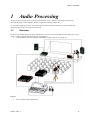
Audio is an important part of any audio-visual presentation or TV production. The Indigo AV Mixer has
powerful and unique tools included to meet the requirement of many productions.
As you read through each section, note that the Tips & Tricks information and Glossary provide additional
definitions and use cases for each of these features.
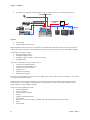
1.1
Overview
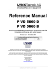
Because of its number and type of inputs and outputs as well as its processing capabilities the audio mixer in the
Indigo is ideally suited for the following types of production:
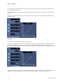
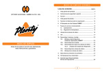
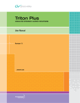
• live presentations like sales trainings, shareholder meetings, Houses of Worship, etc.
Figure 1
•
arena / stadium image magnification
Audio – Rev. x
5
Indigo – AV Mixer
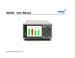
•
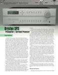
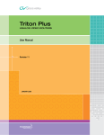
Unilateral TV production at international events e.g. Olympic Games, world championships, etc.
Figure 2
•
•
linear editing
manual Master Control rooms
Motorized Faders with touch sense, Level indicators, and channel On and PFL buttons on the control panel as
well as clear menus with touch screen interaction provide the necessary controls for easy and familiar operation.
Audio inputs and outputs include
• balanced analogue audio
• unbalanced analogue audio
• AES/EBU audio (110 ohm; 75 ohm with a balun)
• embedded audio
This allows connecting a variety of audio sources:
• consumer CD and DVD players
• professional CD and DVD players
• Video Servers/Tape recorders
• Audio Servers
• dynamic microphones
• condenser microphones
Indigo allows connecting up to eight line level or digital stereo sources and up to four microphones – see section
1.2.1 Operation Mode for details.
Indigo does not contain a power amplifier, because the power requirements differ too much from location to
location and the power amplifier would add space, weight and heat. Use an external Public Address system,
power amplifier or active speakers instead.
Audio processing capabilities include
• 48 kHz sample rate
• 24 bits resolution
• stereo and mono channels
• submix
• equalizer (4-band parametric)
• low-cut filter
• dynamics ( compressor, limiter, expander, gate with look-ahead and stereo processing)
• delay
• output limiter
6
Audio – Rev. x
Indigo – AV Mixer
Indigo generates three output signals:
• Main
The Main out – as the name says – is the signal that goes to the Public Address system, the transmitter
or the recording device.
• Sub
The Sub out carries a selectable signal (either main mix or sub mix) which can be delayed.
• Phones
The Phones out is used by the operator for pre-listening. The output has an amplifier for headphones.
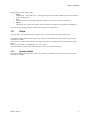
The next sections guide through the setup and the operation of the audio mixer.
1.2
Setup
The setup topics are explained below in a logical order – not necessarily in the order of the menus.
The Operation Mode determines the architecture of the mixer and defines how many and what type of mixer
channels are available.
Next, Inputs are routed to mixer channels, and (physical) Faders are assigned to mixer channels and/or output
faders.
Output levels and audio re-embedding is set in 1.2.4 Output.
Associated audio for audio-follow-video operation is set in 1.2.5 Audio Processing.
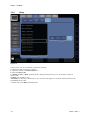
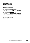
1.2.1
Operation Mode
The Operation Mode determines the architecture of the mixer and defines how many and what type of mixer
channels are available.
Audio – Rev. x
7
Indigo – AV Mixer
Figure 3
There are three choices available:
• 8 Stereo
The mixer operates with eight channels of stereo signals. The channels are named Stereo1 through
Stereo8.
• 7 Stereo 2 Mic
The mixer operates with seven channels of stereo signals and two channels of mono signals. The
channels are named Micro1 through Micro2 and Stereo1 through Stereo7.
• 6 Stereo 4 Mic
The mixer operates with six channels of stereo signals and four channels of mono signals. The channels
are named Micro1 through Micro4 (mono) and Stereo1 through Stereo6.
A stereo channel gets an input pair (L & R) or a digital stereo pair routed in the Audio Input tab. In the mixer
menu a stereo channel has fader and a balance control.
A mono channel pair – Micro1 & Micro2 is a pair and Micro3 & 4 is a pair - gets an input pair (L & R) or a
digital stereo pair routed in the Audio Input tab. In the mixer menu a mono channel has a fader and a panorama
control.
8
Audio – Rev. x
Indigo – AV Mixer
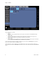
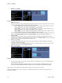
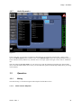
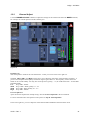
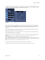
1.2.2
Input
In the Setup – Audio – Input tab the physical audio inputs are routed to the inputs of the available mixer
channels.
Figure 4
In the left Mixer Inputs list box you see the available mixer channels depending on the selected Operation
Mode.
The mono channels Micro1/2 and Micro3/4 are shown as a pair because the inputs are also routed as a pair – the
L (left) part of the signal gets routed to the channel with the lower number. In the Figure 4 above Micro 3 & 4
have the input TRS 4 routed to them. That means: the signal from the TRS 4 L connector goes to channel Micro3
and the signal from the TRS 4 L connector goes to channel Micro4.
Stereo channels are routed as a pair always.
It is possible to route physical inputs to multiple mixer inputs.
The available physical audio inputs are:
•
•
SineGen
The internal sine generator. You can also select the frequency: 440 Hz (the note a’), 1 kHz or 10KHz.
The frequency selection is for the sine generator: When the generator is routed to more than one mixer
input it has the same frequency everywhere.
RCA1, RCA2
Two pairs of unbalanced analogue inputs suitable for consumer audio equipment.
Audio – Rev. x
9
Indigo – AV Mixer
•
TRS3 through TRS8
Six pairs of analogue audio inputs for line level.
Figure 5
•
•
•
•
TRS Source Level
For every input you can also define whether the source has a low, mid, or high voltage output. In other
words you select the nominal sensitivity of the A/D conversion.
Low + 4dBu: a level of +4dBu is full range 0dbFS. in other words a peak voltage of 1.73V is
the full range of the A/D conversion and higher levels are clipped.
Mid +16dBu: a level of +16dBu is full range 0dbFS. in other words a peak voltage of 6.91V is
the full range of the A/D conversion and higher levels are clipped.
High +28dBu: a level of +28dBu is full range 0dbFS. in other words a peak voltage of 27.5V
is the full range of the A/D conversion and higher levels are clipped.
This selection is for the physical input: The same TRS input cannot be used with different Source Level
settings. The Channel Gain adjustment in Channel Adjust is used to fine tune the sensitivity.
XLR7, XLR8
two pairs of XLR connectors (combo connector with TRS7 and TRS8). The XLR inputs have the
microphone pre-amplifiers. The Pre Gain for them is adjusted in Channel Adjust. Do not use the XLR
inputs for audio sources with high line level output power.
AES1 through AES6
six digital audio inputs (each one is stereo). The optional INDGO1-AUDIO-CABLE has the XLR
connectors for inputs and outputs.
The digital coding of the S/PDIF digital audio format is compatible with those inputs. Use of a proper
balun or transformer is recommended in this case.
SDI 1 through SDI 12
the 12 digital video inputs of the Indigo base unit have de-embedders for the embedded audio.
Figure 6
•
For every mixer input you can select any stereo pair in any of the four groups. This includes different
pairs of the same video input.
Note: The HD-SDI inputs on the HiRes card do not have de-embedders. Embedded audio in these
signals must be de-embedded externally and then can be connected to the AES inputs of Indigo.
Indigo cannot use the audio of the IEEE 1394 (DV) inputs, so these can not be selected.
AES and embedded audio can carry proprietary encoded surround audio (e.g. Dolby® E). Indigo does not
process such signals.
10
Audio – Rev. x
Indigo – AV Mixer
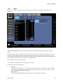
1.2.3
Fader Assignment
Figure 7
In Setup – Control Panel – Fader Assign you assign channel faders to the six physical Faders on the Indigo
surface.
Select the physical Fader in the left box and select the channel fader or an output fader in the right box and press
the Assign button. The selectable channel faders depend on the operation mode. In addition to those you can
select the Main Out, Sub Out and Add-Sub-to-Main faders as well as None. None means the Fader on the
surface is not active.
Default All assigns the first six channel faders to the six physical faders. Default assigns the default channel
fader to the selected fader.
Audio – Rev. x
11
Indigo – AV Mixer
1.2.4
Output
Figure 8
In this menu you define the setup for the audio outputs.
Main Out
Select the VU Source, i.e. if you want the PFL (“pre masterfader”) or the AFL (“after masterfader”) signal to be
displayed by the main VU meter on the right side of the screen.
You can also set the XLR Out Level (i.e., the output gain after the D/A conversion). With digital full scale
(0dBFS) you can have +4dBu, +12dBu, +16dBu or +24dBu analogue output level.
Sub Out
Select the source of the Sub Out: it can be either the Main Mix or the Sub Mix.
Select the VU Source to be displayed by the Sub VU meter on the right side of the screen.
You can also set the TRS Out Level.
In addition, you can set a Delay in milliseconds (independently for left and right channel), for example, to
compensate distances between the speakers. See more in Tips & Tricks.
Embedded Audio
Here you set which SDI video output will have the audio re-embedded into the digital video signal. The Main
Mix is in Pair 1 Group A and the Sub Mix is in Pair 2 Group A.
12
Audio – Rev. x
Indigo – AV Mixer
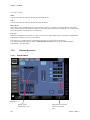
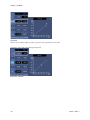
1.2.5
Audio Follow Video
Figure 9
In this section you enable Audio Follow Video and assign the related audio to the video. It is possible to assign
the same audio to multiple video sources. And, of course some video sources may not have a related audio.
To enable Audio Follow Video:
1. Press AVF Enable. The Video Sources list is displayed.
2. Select the video signal from the Video Sources list. You can also select Stills from this list.
3. Press Audio Sources. The Audio Sources list with the available mixer channels is displayed.
4. Select the audio input from the Audio Sources list.
5. Press Level-Set. The volume output level faders for the volume output level are displayed.
6. If desired, you can change the volume level (in dB) for “on air” (right fader) and “off air” (left fader).
Normally the “off air” level is -∞, but if the source should stay audible then this value can be higher. If needed
for some unusual reason the “off-air” level can be higher than the “on-air” level.
Audio – Rev. x
13
Indigo – AV Mixer
1.2.6
Delay
Figure 10
In this section, you can set the delay for the mixer channels
To change the delay settings for a channel:
1. Select the channel in the Mixer Inputs list.
2. Select the Delay Units.
For Fields and msec, a Delay parameter field is displayed which allows you to set the delay in fields or
milliseconds.
No Delay sets the delay to zero.
Auto Delay sets the delay automatically in sync with the video signal. For example when the audio was deembedded from the video.
3. Set the delay in the Delay parameter field.
14
Audio – Rev. x
Indigo – AV Mixer
1.2.7
Audio Dynamics
Figure 11
In this setup page, you can select a compressor sidechain input for each mixer channel input . Select a mixer
input in the Mixer Inputs listbox and then select in the Sidechain Input listbox the required sidechain input, or
switch sidechain off. By default every Channel uses its own input signal for the gain control. This is “Sidechain
off”.
With the radiogroup Pre/Post Fader you can choose if you take the sidechain signal before the channel fader
(Pre) or after the channel fader (Post). In any case the sidechain signal includes the EQ and Dynamics processing
of that channel.
1.3
Operation
1.3.1
Mixing
The audio mixing is controlled using the audio subpanel and the Mixer menu.
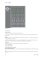
1.3.1.1
Audio Control Subpanel
Audio – Rev. x
15
Indigo – AV Mixer
Figure 12
The elements are:
Master Volume
The Master Volume knob lets you adjust the Main Out level.
The six Fader strips control the assigned channel. (It is a good idea to label the strips with adhesive tape in the
bottom area.)
Fader
The fader adjusts the level of the assigned Mixer channel within the range of -∞ to +10 dB. (If an output level is
assigned, the range is -∞ to 0 dB.)
The faders are motorized and will move (e.g. when an E-MEM register is recalled or by audio-follow-video).
Because of touch sensing you can intervene manually by touching or moving the fader.
LED Meters
The meters show the level of the assigned channel with three different colours:
• Green: -∞ to -6 dB
• Yellow: -6 dB to -2 dB
• Red: -2 dB to +10 dB
Mute and PFL Buttons and LEDs
PFL (Pre-Fader-Listening)
Changes to PFL mode. This allows you to hear the audio signal on the headphones as it sounds before the fader.
On
Turns the assigned audio channel on or off. This is useful to turn off a microphone channel but leave the fader
where it is.
16
Audio – Rev. x
Indigo – AV Mixer
Headphones (not pictured)
On the left hand side of the Indigo AV mixer you find a TRS connector for headphones and the headphones
volume knob. (There is a second Phones output on the rear panel; it has a separate amplifier but the same signal
and volume.)
The Headphone output is used for prelistening and monitoring.
When the PFL mode is active for one channel, you prelisten to that channel, when PFL mode is active for several
channels you prelisten to (the sum of) those channels. When no channel is in PFL then you hear the signal
selected in the Audio Mixer – Output menu for Phones Out. (You have the choice for Main Out or Sub Out and
Pre- and After- Fade for both)
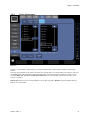
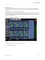
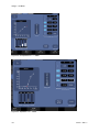
1.3.1.2
Audio Mixer – Mixer menu
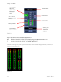
Figure 13
This is the menu where you see and operate all channels at once.
Every channel is displayed like this:
Audio – Rev. x
17
Indigo – AV Mixer
“On” indicator
and switch
(shown “On”)
When off the
channel is
muted
Channel Name
Channel Fader
“PFL” indicator
and switch (shown
inactive)
Channel Meter
Settings indicator
Type indicator
(Stereo or Mono)
Balance (resp.
Panorama)
Control with
indicator
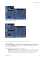
Figure 14
The Settings indicator shows (from left top to right) bottom:
EQ
Equalizer is active (see Channel Adjust menu)
DN
Dynamics (Compressor / Limiter / Noise gate) are active (see Channel Dynamics menu)
M
Channel is mixed into the Main-Mix (see Channel Adjust menu)
S
Channel is mixed into the Sub-Mix (see Channel Adjust menu)
The meter on the right side (which is present in all menus) can be switched to display Main Out, or Sub Out, or
both just by touching the area.
Figure 15
18
Audio – Rev. x
Indigo – AV Mixer
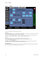
1.3.2
Channel Adjust
Use the CHANNEL ADJUST submenu to adjust the settings for the channel selected in the MIXER submenu,
for example, the 4-band equalizer and the Channel gain.
Figure 16
Equalizer On
turns the Equalizer on/off for the selected channel – which you can see in the lower right box.
The Low, Mid 1, Mid 2, and High sections allow you to adjust the four filters of the parametric equalizer. A
positive Gain amplifies the frequency band and a negative gain reduces it. The frequency of each of the four
bands can be set individually. You may also set the Q factor (quality) – i.e., the width of the filter – for the Mid 1
and Mid 2 bands.
Low
Freq. 20Hz - 400Hz
Mid1 Freq. 150Hz - 4kHz, Quality 0.1 – 4.5
Mid2 Freq. 1kHz - 8kHz, Quality 0.1 – 4.5
High Freq. 4kHz - 20kHz
Presets Clipboard
opens the Presets Clipboard for the EQ settings. See also Presets Clipboard in the User Manual.
For more information how the equalizer works please see Tips & Tricks Equalizer.
In the lower right box, you see a duplicate of the Channel fader and Balance from the Mixer menu.
Audio – Rev. x
19
Indigo – AV Mixer
Also you can select
Main
Activate this button to make the channel part of the MAIN mix.
Sub
Activate this button to make the channel part of the SUB mix.
Phase Invert
This button is only available if this is a mono channel - which you typically use for Microphones. It shifts the
phase of the monaural audio signal 180 degrees to match the phase of the other microphones – for example if the
microphone cable accidentally has reversed polarity.
Low Cut
Attenuates frequencies below 80 Hz, to reduce low-level noise (aka rumble). This is especially recommended if
a Microphone signal is the source of the channel.
Left of this box is a slider that lets you adjust the input level to get a good level for mixing.
For a LINE or DIGITAL input the slider is Channel Gain. Pre Gain is for the inputs with Microphone
preamplifiers – the XLR Inputs.
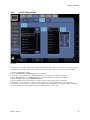
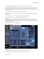
1.3.3
1.3.3.1
Channel Dynamics
Standard Mode
Figure 17
Display of the
Characteristic curve
20
Adjustment of the points
of the Characteristic
curve
Audio – Rev. x
Indigo – AV Mixer
With the Channel Dynamics menu you can change the dynamic behaviour of the channel.
The five points in the In/Out Level group construct the characteristic input-to-output-level curve displayed in
the box on the left side. These five points also give you the possibility to combine Limiter, Compressor,
Expander and Noise-gate in one stage. For simpler processing the points 2, 3, and 4 can be disabled individually
with the numbered button.
The VU Meter in the middle shows the Input Level of the dynamics stage.
The Chan Gain group allows to adjust the input gain which identical to the Channel Gain in the Channel
Adjust menu.
In the Compressor group you can adjust attack-time, release-time and output level.
With the A<>B button you can exchange your settings with the clip-board.
The Sidechain gives you the possibility to control the channel dynamics from a different channel. The
Sidechain button enables/disables this feature and is only present when a sidechain input has been selected. The
name of the sidechain input is shown inside the button in brackets. You can select the sidechain input in the
Setup- Audio - Dynamics menu.
Expert Mode changes the menu to Expert Mode.
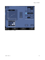
1.3.3.2
Expert Mode
Figure 18
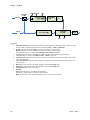
In the Expert Mode you can manually adjust more settings of the dynamics processor.
In order to better understand the Expert Mode Settings here is a Block diagram:
Audio – Rev. x
21
Indigo – AV Mixer
Figure 19
•
•
•
•
•
•
•
•
•
22
Sidechain On/Off selects whether the channel signal itself or the sidechain input is used. It is only
present when a sidechain input has been selected in Setup > Audio > Dynamics.
Attack adjusts how fast the Peak Level Detector follows a rising signal.
Release adjusts how fast the Peak Level Detector follows a falling signal.
The adjustment group is visible when Method Peak or Both is selected.
AvgT adjusts how fast the Average Level Detector follows the signal (rising or falling).
The adjustment is visible when Method AVG or Both is selected.
Characteristic Curve defines the relation of input to output levels and determines the Gain of the
Controlled Amplifier.
Look Ahead Delay delays the audio signal to compensate for latency in the detector path. It is set
automatically..
Rise adjusts how fast the Controlled Amplifier follows increasing Gain.
Fall adjusts how fast the Controlled Amplifier follows decreasing Gain.
Output Gain adjusts the output level.
Method:
Peak: the Peak detector is used for the Dynamics.
AVG: the average detector is used for the Dynamics.
Both: both detectors are used and the higher level is used for the Dynamics.
Audio – Rev. x
Indigo – AV Mixer
1.3.4
Output
Figure 20
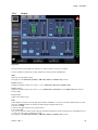
This menu has been changed from “Monitor” in earlier software versions to “Output”.
Use this submenu to adjust the volume of Main Out, Sub-Out and the headphones.
Mute
Mutes the corresponding output.
This applies to the Main Out, Sub Out, Add Sub to Main, and Phones Out sections.
Limiter (button)
Enables the Output Limiter (new since V 1.2.11). (Main Out, Sub Out and Phones Out)
Limiter (slider)
Adjusts the Output Limiter (new since V 1.2.11) (Main Out and Sub Out. For the Phones Out the Limiter is
fixed to 0dB.)
Level (sliders)
Adjusts the Output Levels.
Link
Links/unlinks an output’s left and right channel faders. If Link is on, moving one fader automatically moves the
other one. Unlink the faders for balancing different left and right audio levels:
1. Deactivate Link.
2. Set left and right channel to the required levels.
3. Activate Link.
Now you can turn the volume of the output up and down without the need to compensate for the different levels.
(i.e. the previously set level difference is kept.)
This applies to the Main Out, Sub Out, Add Sub to Main, and Phones Out sections.
Audio – Rev. x
23
Indigo – AV Mixer
Add Sub to Main
Use these faders to mix the Sub-Mix to Main-Mix.
Phones Out
The Phones Out section has some additional buttons:
• Main
Allows you to hear the signals of the Main output on the headphones. This button is only available if no channel
PFL is active.
• Sub
Allows you to hear the signals of the Sub output on the headphones. This button is only available if no channel
PFL is active.
• PFL/AFL
Choose if you want to hear the signals of the Main and Sub outputs in AFL or PFL mode on the headphones.
These buttons are only available if no channel PFL is active.
• Channel PFL
This button is only available if at least one channel PFL is activated. Press it to deactivate all channel PFL.
• 100%/50%/25%
Allows you to set the power of the phone amp to adjust it to your headphones.
The faders of the Phones Out section control the volume on the headphones and work in parallel with the knob
on the Indigo panel.
1.3.5
Presets Clipboard
The Preset Clipboard is used in the Channel Adjust and Channel Dynamics menu to recall fixed and user preset
settings and save the user presets.
Button Functions
The clipboard will only affect (a subset) of the parameters shown on the current dialog. It stores a copy of each
parameter in volatile memory that is lost after power cycle. The initial state of the clipboard after power up
equals the default settings.
• Load
A dialog appears to load a specific preset file from the USB Flash Memory.
• Save
A dialog appears to store the current settings as preset to the USB Flash Memory.
• Copy
Copies the current parameter settings and the values stored to the clipboard.
• A <> B
Toggles between the current parameter settings and the values stored on the clipboard. This is useful to
compare two EQ or Dynamics settings.
• Paste
Upgrade parameters with the current clipboard content.
• Cancel
Closes the Preset/Clipboard dialog.
• Built-in Presets
There are several fixed presets suitable for the current dialog.
User Presets saved from the Channel Adjust menu will contain the Equalizer settings, but not level, balance,
Channel Gain and Low Cut. The saved file has the extension “.eq”.
User Presets saved from the Channel Dynamics menu will contain the Dynamics settings, but not the Input Gain.
The saved file has the extension “.dyn”.
24
Audio – Rev. x
Indigo – AV Mixer
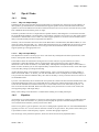
1.4
Tips & Tricks
1.4.1
Delay
1.4.1.1 Why use Output Delay?
Sometimes the PA system used has support speakers that are positioned away from stage into the audience. If
those speakers get the MAIN mix, the sound from the support speakers arrives before the sound of the main
speakers in front of the auditorium. The brain of the listener has to do a lot of work to associate the early sound
from a different direction with the person on stage.
If the PA system does not have a compensation for speaker distance, then Indigo has: You select the main mix
for the SUB output and delay it. Sound speed is approximately 340 meters per second. or in other words it takes
sound about 3 milliseconds to travel 1 meter. So, if the support speakers are 10 meters into the audience then a
delay of 30 milliseconds just about compensates the distance.
The delay can be increased a bit more because of the Haas effect. The Haas effect (after Helmut Haas) or “Law
of the wave front” describes that a 10 – 30msec delayed signal may be up to 10dB higher in level but is still not
separated from the original and the first wave front gives the directional information to the listener and the
support speakers give the appropriate level.
1.4.1.2 Why use Input Delay?
This adjustment is used to correct lip-sync issues. The video may be delayed in the frame synchronizer, in the
DVE, in the upscaler and in the downscaler.
If the audience hears the sound before seeing the action in the video, this is quite unnatural. In order to
compensate: evaluate the path the video is going through. Frame synchronizer, DVE, upscaler and the
downscaler: each one has one frame (or two fields) delay. Add together and adjust the delay to that number of
fields. For finer resolution you can also adjust the delay in milliseconds. You will also want to check and maybe
correct the delay setting by looking and listening.
Another thing that delay can be used for is double tracking. This is a technique used in recording studios to
make voices sound “fuller.” To do this, you route the same audio source to multiple mixer channels and give
every (but the first) channel a different delay. The value of the delay is strictly an artistic decision so there is no
recommendation here.
Up to the “echo threshold,” the ear and brain do not separate the sound events but instead accumulate them. The
echo threshold depends on the type of sound and the level. With pulses (drums) and/or high sound pressure
levels the echo threshold is lower than with strings or vocals and at lower levels. Some sources give 30 – 50
msec as the lowest echo threshold. With a noticeable delay (echo), the illusion of a room can be created, the
room appearing larger with longer delays.
Many creative things can be done here. Consider further reading on recording techniques.
1.4.2
Equalizer
An Equalizer is a tool that amplifies or suppresses certain frequency bands. For example, in an auditorium with
heavy carpet, thick curtains and so on, you may need to amplify the presence and treble frequencies and in a
room with bare floor and walls you may need to lower them.
There are two generic types of equalizer. First, the so-called graphic equalizer has a set of fixed bandwidth filters
(typically an octave or 1/3 octave) each of which has a slider for its gain control. The position of the sliders gives
a representation of the overall frequency response – thus the name graphic equalizer.
The second type is the parametric equalizer, which uses fewer but more freely adjustable filters.
Audio – Rev. x
25
Indigo – AV Mixer
Indigo has such a parametric equalizer with four bands for each channel that you enable and adjust in the
Channel Adjust menu.
There is a LOW band and a HIGH band where you can adjust the gain and the cut-off frequency and two mid
bands where you can adjust gain, centre frequency and quality.
Quality or Q-Factor is the relation of centre frequency to bandwidth. That means the higher the Quality is the
smaller the bandwidth of the filter and the lower the quality is, the wider the filter.
For example: with centre frequency 1 kHz and a quality of 1, the bandwidth is 1 kHz as well, so very simplified
speaking the filter influences frequencies from 500Hz to 1500Hz. In reality the bandwidth is not symmetric to
the centre frequency: with Q = 1 the bandwidth is 618 – 1618 Hz and with Q = 0.5 it is 414 – 2414 Hz. The
product of the lower and the upper frequency equates the squared centre frequency. Also the filter slope is not
infinitely steep.
For the musicians: a quality of 1.4 results in a bandwidth of 1 octave and Q = 3.3 is 1/3 octave bandwidth.
To start off with equalizing the Indigo has a couple built in presets you can recall from the preset clipboard.
Let’s look at the DEFAULT:
Figure 21
The gain is flat in all bands but let’s look at the frequencies:
• The cut-off for the LOW band is lower than the fundamental notes of most voices.
• The Mid1 band’s centre frequency and Q-factor create a filter with which you can emphasize or lower
the fundament and lower harmonics of voices and instruments.
• The Mid2 band is set for the brilliance frequencies. With a bit emphasize here the voice or instrument
sounds more “brilliant” and “Present”.
• The High band is the higher harmonics of instruments and voices and also this where sibilance can
occur. Lowering here can make that less noticeable.
Have also a look at the other built-in presets.
26
Audio – Rev. x
Indigo – AV Mixer
Rock gives you more bass and treble and lowers the mid frequencies.
Figure 22
Pop is similar but more flat.
Figure 23
Classic reduces bass and presence and adds in the lower mids and treble
Figure 24
Once you started working with the EQ you will find adjustments that you want to re-use.
You can save those presets on your USB-flash-drive in the PRESET CLIPBOARD.
Every situation and auditorium is different so we cannot give general rules how to adjust the EQ. You can search
the Internet and study literature on sound recording. Also by start working you will make your own experience.
Audio – Rev. x
27
Indigo – AV Mixer
Just one tip for presenter microphones: Depending on the microphone model and the distance it has to the
speaker, the fundamental notes get amplified. As a consequence, the sound may get dull and cannot be
understood very well.
You can lower the frequency band from about 180 – 300Hz.to avoid that. Use Mid1 and adjustment centre
frequency to 240Hz and Q=2. Start with a level -3dB and adjust so the sound is not too thin. In order to improve
understandability (at least acoustically) you can emphasize the range from 2 – 4 kHz. We use Mid2 band and set
frequency to 2.8 kHz and Q = 1.4. Adjust the level so the sound becomes clear but not high-pitched. Also you
may need to lower the LOW band to suppress humming and rumble and lower the HIGH band to reduce the
‘s’es.
1.4.3
Dynamics
1.4.3.1 What is Dynamics? And why use it?
Dynamics is the generalized term for an audio processing stage with variable gain – which is controlled
depending on the level of the signal. Typical examples are: Compressor, Limiter, Expander, and Noise-Gate.
A Limiter is used to protect electronic devices like power amplifiers, modulators, or A/D converters from being
overloaded. A power amplifier may need to produce excessive current, a modulator for radio transmission may
exceed allowed bandwidth, an A/D converter may clip when overloaded. Instead of just clipping at a specified
level a Limiter reduces the gain so that a certain output level is not exceeded. A clipper would just clip and thus
create harmonic distortion. (That is why clippers are used to create the distortion effect e.g. for guitars). A
Limiter avoids the distortion.
A Compressor (see also Standard Compressor ) also reduces the gain when a certain input level is exceeded. It
still allows higher output levels, but the output level is compressed by the compression ratio.
Some acoustical musical instruments have a different volume depending on the notes played. Also singers and
speakers (especially untrained) have difficulties to keep an equal volume. A properly adjusted compressor evens
volume differences out but still leaves ‘life’ in the sound. A speaker will be much better understandable –
acoustically – when the volume is evened out by a compressor which makes the average volume louder. You can
hear extreme cases in the sound of many commercial advertisements on radio and TV.
An Expander reduces gain when the level gets below a certain threshold. This is used to reduce unwanted
sounds such as the noises a guitar player makes on the fingerboard or sound from other instruments.
A Noise-Gate is the extreme of an Expander. When the level gets below a certain threshold the gain is reduced to
zero. Again this is used to eliminate unwanted sounds.
28
Audio – Rev. x
Indigo – AV Mixer
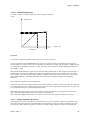
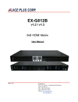
1.4.3.2 Standard Compressor
For those not familiar with this effect here is how a typical compressor
works:
Output Level
Input Level
Threshold
Figure 25
A compressor reduces the dynamic range of the voice or music in this way:
Above a certain level called THRESHOLD this stage has a lower gain which is reduced by the Compression
RATIO. Effectively louder input levels are reduced on the output. For example with Threshold = -20dB and ratio
4:1 an input level of 0dB gets reduced to -15-dB – Basically all levels between -20dB and 0dB get compressed
into -20dB to -15dB.
With the GAIN adjustment the output level is raised to make it louder again. In this example we set the gain to
15dB and then an input level of 0dB has an output level of 0dB but an input level of -20db now has an output
level of -5dB – this is much louder. So the signal has a higher average level and that causes more “power” and
better understandability. The further advantage versus just a gain of 15dB is: no higher risk of clipping
distortion.
The compressor stage has two more adjustments:
ATTACK controls how fast the gain reduction above the threshold is invoked. A short ATTACK time eliminates
even short peaks and a long ATTACK time will let short peaks pass through nearly uncompressed. Typically it is
several milliseconds up to a couple hundred milliseconds.
RELEASE controls how fast the compressor returns to normal gain when the level gets below the threshold
again. Typically the RELEASE time is longer than the ATTACK time.
Short ATTACK and RELEASE makes the compressor react faster and longer times make it react slower.
1.4.3.3 Indigo’s Dynamics processor
The Indigo has an advanced dynamics processor that allows it to be an expander, compressor and limiter at the
same time. The signal path has a look-ahead delay that compensates for latency in the level detection and gain
control stages. Most commonly dynamics processors are used in Mono Channels. Indigo can do dynamics in
Audio – Rev. x
29
Indigo – AV Mixer
stereo channels, by using both channels in the detection, and control the gain in both channels equally so that
stereo panorama does not move.
When turning Dynamics On you have already a 0dB Full Scale limiter which already greatly avoids clipping
distortions.
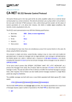
The input-to-output characteristic is programmed with up to five points which are adjusted and enabled in the
In/Out Level box.
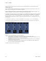
Figure 26
To start with let us put them on a straight unity-gain line.
To adjust the compressor, select point 1 and reduce the output level. You are adjusting the compression ratio
above the threshold that is defined by point 2. The next images show the setting for a 4:1 compressor ( input
levels between -20 dB and 0 dB – that is a 20 dB range - get compressed into -20dB to -15dB output level – that
is a 5 dB range. 20:5 = 4:1
Figure 27
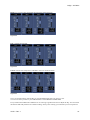
When further reducing the point 1 output level until it has reached point 2 output level you get a LIMITER with
-20dB limit. Further reducing point 1 output level will reduce the point 2 output level automatically.
30
Audio – Rev. x
Indigo – AV Mixer
To build a Noise-Gate select point 4 and reduce its output level to -100. Input levels below -80dB will be gated
to -100dB (in the Indigo that is the same as -∞). The segment between point 3 and 4 is an Expander (the input
level range -80 to -40 dB gets expanded into output levels -∞ to – 40dB).
Figure 28
Just to recap the Compression or Expansion ratio is calculated as the relation of the difference of the Input
Levels to the difference of the Output Levels of the segment of the characteristic curve. Compression Ratios of
2:1 to 5:1 can be used without making the compression too obvious. Indigo has a fixed preset for a 4:1
compressor.
In this example the peak output level has been reduced to -15dB. With Out Gain the output level can now be
brought up by 15dB and this increases the average volume!
Please take care: when you are in an auditorium this may increase the probability of getting feedbacks. A PA
System with feedback destroyer will greatly help.
For the adjustment of ATTACK and RELEASE times there is no fail-safe recipe. It always depends on what is
needed.
Attack and Release very short (1 – 10ms): about every syllable may cause the Compressor to react
Attack and Release long: whole groups of words cause the compressor to react.
Attack and Release too long: Listeners start to hear the Gain-Adjustment going on. That should be avoided.
Attack short and Release too long (> 0.5 sec) then short pulses of the speaker can reduce the gain for quite along
time.
For a speaker an ATTACK of 1ms and a RELEASE of 200ms can be a start.
Use the A-B button a lot to compare two settings and decide which one works better.
An adjustment like the following could be used to counter a too high compression of the source.
Audio – Rev. x
31
Indigo – AV Mixer
Figure 29
Input levels of -5dB to 0dB (e.g. today’s pop music) get expanded to -20 to 0 dB.
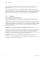
The Indigo comes with the following fixed presets.
Figure 30: "Default"
32
Audio – Rev. x
Indigo – AV Mixer
Figure 31 "Compr. 2:1 > -50dB"
Audio – Rev. x
33
Indigo – AV Mixer
Figure 32:"Compresssor 4:1 > -20dB"
Figure 33 “Expander 1:3 < -20dB“
34
Audio – Rev. x
Indigo – AV Mixer
Figure 34 “Expander 1:4 > -5dB“
Figure 35: "Noise-Gate -60dB"
In addition to those fixed presets you can save your own on the USB flash drive.
1.4.3.3.1
Sidechain
As explained above a Dynamics processing stage has a main signal path (where the gain varies) and a level
detection and gain control path. The latter one is often called ‘sidechain’. Many specialized compressor devices
have an input called sidechain where a different signal can be plugged in. When enabled, this signal then
controls the gain of the main signal path.
This feature can be used as a creative effect or for special purposes.
• “Ducking”, automatic voice-over
For this function you use a microphone as the sidechain for the channel where the music is on. Make it
a compressor that reduces the level – do not increase Output Level. Set Attack to a short time and
Release to a medium to long time. Now when the Speaker starts talking the music is automatically
reduced in level. When he pauses (for longer than the Release time) it comes up again.
Audio – Rev. x
35
Indigo – AV Mixer
•
De-esser
Remember the sibilance in the higher frequencies? Just reducing the high frequencies in the equalizer
may not be enough. This can be improved by using EQ and Dynamics: Take the same input into a 2nd
channel, turn on the EQ and amplify above 6kHz or so and reduce Low and Mid, and then use this as
the sidechain input. Now with short Attack and Release the dynamics processor working as a De-esser.
The Sidechain input is selected in Setup Audio Dynamics.
By default every Channel uses its own input signal for the gain control. This is “Sidechain off”.
You can also select whether you use the Pre Fader signal or the Post Fader signal. When selecting Pre-Fader the
signal on the sidechain input - which controls the gain in the dynamics - is taken before the channel fader. In
consequence the level is independent from your mix. When selecting Post-Fader, the signal is taken after the
channel fader. Consequently, the dynamics gain is then dependent on your mix.
In any case the sidechain signal includes the EQ and Dynamics processing of the selected channel.
You enable the sidechain input in the Channel Dynamics menu.
36
Audio – Rev. x
Indigo – AV Mixer
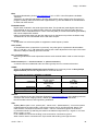
1.5
Technical Notes
1.5.1
Connections
See Indigo User Manual section 3.6 Audio Connections
1.5.2
Mixer
The mixer operates at 48 kHz sample rate with 24 bit resolution.
The AES/EBU inputs and the de-embedders from the SDI video inputs have built-in sample-rate converters. It is
not necessary to synchronize the digital audio sources with a word clock or AES sync.
Due to the sample rate converters, Indigo also accepts digital audio signals with 32 kHz, 44.1 kHz (CD Audio),
and 96 kHz sample rate.
The AES/EBU digital audio data format has provision for “Audio sample word used for purposes other than
linear PCM samples”. This possibility is used by some manufacturers for proprietary audio formats. Indigo does
not process such formats. An example of such a proprietary format is Dolby E – which can also be found in
embedded audio – a format that encodes surround audio into one stereo pair.
The Phones Out outputs can drive headphones and speakers with impedance of 16 Ohm and higher. Output
Power is about 1 Watt – which depends on the load resistance.
The XLR inputs have an analogue pre-amplifier which is controlled as Pre-Gain in the Channel Adjust menu
of the channel that has an XLR input. The Channel Gain of the channels with TRS, RCA or digital input signal
works in the digital domain.
The low-cut filter is a 24dB per octave filter with ~80 Hz corner frequency.
Audio – Rev. x
37
Indigo – AV Mixer
1.6
Glossary
AES
Audio Engineering Society (http://www.aes.org) a professional society devoted exclusively to audio
technology. Technical standards are continually being developed under the auspices of the society.
Many of them have since been accepted by international standards organizations as the model for
their standards on the same material.
AES/EBU (digital) audio
Commonly used term for the broadcast & professional standard digital audio format.
The format is standardized by documents of the AES (standard AES3), the EBU and the IEC. The
interface is designed to carry two channels of "periodically sampled and linearly represented"
audio. Recommended sample rate is 48 kHz. Quantization is 16, 20 or 24 bits per sample, coding
is PCM. This and other information is coded in the signal itself. The signal is transported using 110
Ω twisted pair cable or 75 Ω coaxial cable (informational document AES-3id). The interface allows
for “Audio sample word used for purposes other than linear PCM samples” as well; for example
proprietary encoded surround audio. Indigo processes AES/EBU audio but only the linear PCM
coded audio.
Audio follow Video
A technique used in TV and AV production. When a transition or cut from one (background) video
to another is made the audio mixer fades the associated audio signals automatically. Of course, the
audio source must be associated to the video source in the setup.
balun
Pronounced /'bæl.ʊn/ ("bal-un"), is a passive electronic device that converts between balanced and
unbalanced electrical signals. They often also change impedance. In many cases the balun is a
transformer.
dB (decibel)
A logarithmic unit of measurement that expresses the magnitude of a physical quantity (usually
power or intensity) relative to a specified or implied reference level.
Taking voltage as an example, this leads to the equation:
where V1 is the voltage being measured, V0 is a specified reference voltage, and GdB is the power
gain expressed in decibels.
dBFS or dBfs
dB(full scale) — the amplitude of a signal (usually audio) compared to the maximum which a device
can handle before clipping occurs. In digital systems, 0 dBFS (peak) would equal the highest level
(number) the processor is capable of representing. Measured values are usually negative, since
they should be less than the maximum.
dBu or dBv
dB(0.775 VRMS) — voltage relative to 0.775 volts. Originally dBv, it was changed to dBu to avoid
confusion with dBV. The "v" comes from "volt", while "u" comes from "unloaded". dBu can be used
regardless of impedance, but is derived from a 600 Ω load dissipating 0 dBm (1 mW).
Dynamics
The generalized term for an audio processing stage with variable gain – which is controlled
depending on the level of the signal. Typical examples are: Compressor, Limiter, Expander, and
Noise-Gate.
38
Audio – Rev. x
Indigo – AV Mixer
EBU
European Broadcasting Union (http://www.ebu.ch/) a.k.a. UER - Union Européenne de RadioTélévision.
Association of national broadcasters in Europe. Most publicly known activity is the Eurovision TV
program exchange. EBU works with other organizations e.g. AES and SMPTE on standardization
of audio and video formats.
Embedded audio
Digital audio contained in the serial digital video data. The (broadcast) serial digital video format
has bandwidth to carry so-called ancillary data (non-video) data along with the video data and
reference codes. Embedded audio is a form of ancillary data (in the horizontal blanking aka HANC)
that carries multiple AES streams.
Indigo can de-embed audio from the SDI video inputs on the base unit (not from the HiRes-card).
The Main Mix can be re-embedded into the SDI video outputs.
Equalizer
An Equalizer is a tool that amplifies or suppresses certain frequency bands.
Gain (audio)
An amplification factor (output level : input level). Very often gain is expressed in dB with 0dB is
gain = 1 and gain = 0 is -∞dB. Most audio mixers have a Gain adjustment on the input of the mixer
channels to adapt to differing input source levels.
PFL (Pre Fade Listen)
Monitoring audio before level adjustments with the audio channel faders. Used to check the input
audio.
RCA connector(a.k.a. “Cinch-Connector” or “phono connector“)
A coaxial connector unbalanced audio and video typically found in consumer electronics.
S/PDIF
Stands for Sony/Philips Digital Interconnect Format (more commonly known as Sony Philips
Digital Interface) the format of digital audio for consumer devices.
Main Differences between AES/EBU and S/PDIF
AES/EBU
cable 110 ohm shielded twisted pair,
75 ohm coaxial
3-Pin XLR,
connector
25-pin D-sub,
BNC
3 – 10 V
signal level
24 bits
typ. resolution
24 bits
max. resolution
S/PDIF
75 ohm coaxial,
fibre
RCA, BNC,
TOSLINK
0.5 – 1 V
16 bits
20 bits (24 bits optional)
SMPTE
Society of Motion Picture and Television Engineers (http://www.smpte.org) is the leading technical
society for the motion imaging industry. SMPTE publishes ANSI-approved Standards,
Recommended Practices, and Engineering Guidelines.
TRS
Tip-Ring-Sleeve (aka ¼-inch, “phones jack”, “Stereo Jack”, “Klinkenstecker”). A connector used in
professional and consumer audio. It has a triple contact: the Tip, the Ring and the Sleeve. The
cable shield is connected to the Sleeve contact – which is connected to ground in the device.
In professional audio Tip and Ring are used for the balanced signal with Tip = signal+ or ‘hot’ and
Ring = signal- or ‘cold’.
In an unbalanced connection the Ring is not connected or connected to ground.
When used for stereo connections the Tip is the left and the Ring is the right channel.
Audio – Rev. x
39
Indigo – AV Mixer
Indigo uses the ‘balanced’ version on its TRS connectors with the exception of the headphones
outputs which are stereo.
XLR connector
A connector used in professional audio and other applications. The connector is mechanically very
robust. Versions with different number of pins are available. Professional audio uses the 3-pin
version for balanced analogue audio and AES/EBU digital audio.
Some Indigo inputs have a combo socket for 3-pin XLR and ¼-inch TRS.
40
Audio – Rev. x