1
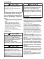
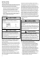
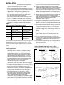
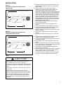
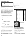
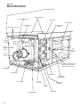
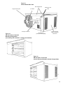
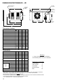
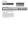
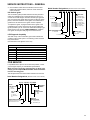
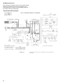
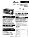
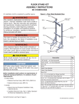
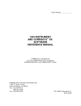
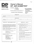
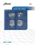
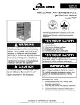
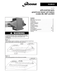
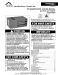
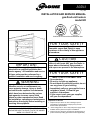
6-576.1
Part 5H74925 Rev.A
July, 1998
INSTALLATION AND SERVICE MANUAL
gas-fired unit heaters
model HD
DESIGN
ERICAN
AM
GAS
O
A
CE
R
N
R
SS
O C I A TI
R TI F I E D
Certified for Commercial and Residential Use
FOR YOUR SAFETY
The use and storage of gasoline or other
flammable vapors and liquids in open
containers in the vicinity of this appliance
is hazardous.
!
IMPORTANT
The use of this manual is specifically
intended for a qualified installation and
service agency. All installation and service
of these units must be performed by a
qualified installation and service agency.
!
WARNING
Improper installation, adjustment,
alteration, service or maintenance can
cause property damage, injury or death,
and could cause exposure to substances
which have been determined by various
state agencies to cause cancer, birth
defects or other reproductive harm. Read
the installation, operating and maintenance
instructions thoroughly before installing or
servicing this equipment.
THIS MANUAL IS THE PROPERTY OF THE OWNER.
PLEASE BE SURE TO LEAVE IT WITH THE OWNER
WHEN YOU LEAVE THE JOB.
CAUTION
To prevent premature heat exchanger
failure do not locate ANY gas-fired units in
areas where chlorinated, halogenated or
acid vapors are present in the atmosphere.
FOR YOUR SAFETY
•
•
•
•
•
WHAT TO DO IF YOU SMELL GAS:
Open windows.
Do not try to light any appliance.
Do not touch any electrical switch; do not
use any phone in your building.
Immediately call your gas supplier from a
neighbor’s phone. Follow the gas
supplier’s instructions.
If you cannot reach your gas supplier,
call your fire department.
Inspection on Arrival
1. Inspect unit upon arrival. In case of damage, report it
immediately to transportation company and your local
Modine sales representative.
2.
Check rating plate on unit to verify that power supply meets
available electric power at the point of installation.
3. Inspect unit upon arrival for conformance with description of
product ordered (including specifications where applicable).
INSTALLATION
SPECIAL PRECAUTIONS
THE INSTALLATION AND MAINTENANCE INSTRUCTIONS IN THIS
MANUAL MUST BE FOLLOWED TO PROVIDE SAFE, EFFICIENT
AND TROUBLE-FREE OPERATION. IN ADDITION, PARTICULAR
CARE MUST BE EXERCISED REGARDING THE SPECIAL
PRECAUTIONS LISTED BELOW. FAILURE TO PROPERLY
ADDRESS THESE CRITICAL AREAS COULD RESULT IN
PROPERTY DAMAGE OR LOSS, PERSONAL INJURY, OR DEATH.
17. Do not install units below 7' measured from the bottom of the unit to
the floor in commercial applications and 5' measured from the
bottom of the unit to the floor in residential applications.
1. Disconnect power supply before making wiring connections to
prevent electrical shock and equipment damage. All units must be
wired strictly in accordance with wiring diagram furnished with the
unit.
19. In commercial garages or other sections of aircraft hangars such as
offices and shops which communicate with areas used for servicing
or storage, keep the bottom of the unit at least 7' above the floor. In
public garages, the unit must be installed in accordance with the
Standard for Parking Structures NFPA 88A and the Standard for
Repair Garages NFPA 88B. In Canada, installation of unit heaters
in airplane hangars must be in accordance with the requirements of
the enforcing authority, and in public garages in accordance with
the current CAN/CGA-B149 codes.
2. Turn off all gas before installing unit heaters.
3. Gas pressure to unit heater controls must never exceed 14" W.C.
(1/2 psi).
When leak testing the gas supply piping system, the unit and its
combination gas control must be isolated during any pressure
testing in excess of 14" W.C. (1/2 psi).
The unit should be isolated from the gas supply piping system by
closing its field installed manual shut-off valve.
4. Check gas inlet pressure at unit upstream from combination gas
control. The inlet pressure should be 6-7" W.C. on natural gas or
12-14" W.C. on propane gas. Purging of gas piping should be
performed as described in ANSI Z223.1—latest edition or in
Canada in CAN/CGA-B149 codes.
5. All units must be vented to the outside atmosphere.
6. Do not install in potentially explosive or flammable atmospheres
laden with grain dust, sawdust, or similar air-borne materials. In
such applications a blower type heater installed in a separate room
with ducting, including appropriate back flow prevention dampers,
to the dust-laden room is recommended.
7. Installation of units in high humidity or salt water atmospheres will
cause accelerated corrosion resulting in a reduction of the normal
life of the units.
8. To prevent premature heat exchanger failure do not locate ANY
gas-fired unit heaters in areas where chlorinated, halogenated or
acid vapors are present in the atmosphere.
9. Do not locate units in tightly sealed rooms or small compartments
(commonly referred to as confined spaces) without provision for
adequate combustion air and venting. Combustion air must have
access to the confined space through a minimum of two permanent
openings in the enclosure, at least one near the bottom. They
should provide a free area of one square inch per 1000 BTU per
hour input rating of the unit with a minimum of 100 square inches
for each opening, whichever is greater.
10. Do not install unit outdoors.
11. Do not locate unit closer to combustible materials than the
clearances listed. They are:
Top and Bottom
1"
Vent Connector
4"
Access Side
18"
Non-Access Side
1"
Rear
18"
12. Allow 18" clearance at rear (or 6" beyond end of motor at rear of
unit, whichever is greater) and access side to provide ample air for
combustion and proper operation of fan.
13. The minimum distance from combustible material is based on the
combustible material surface not exceeding 160°F. Clearance from
the top of the unit may be required to be greater than the minimum
specified if heat damage, other than fire, may occur to materials
above the unit heater at the temperature described.
14. Modine unit heaters are designed for use in heating applications
with ambient temperatures between -40° F and 90° F.
15. Be sure no obstructions block air intake and discharge of unit heater.
16. Do not attach duct work, air filters, or polytubes to any HD unit heaters.
2
18. In aircraft hangars, keep the bottom of the unit at least 10' from the
highest surface of the wings or engine enclosure of the highest
aircraft housed in the hangar and in accordance with the requirements of the enforcing authority and/or NFPA 409 – latest edition.
20. Consult piping, electrical, and venting instructions in this manual
before final installation.
21. All literature shipped with this unit should be kept for future use for
servicing or service diagnosis. Do not discard any literature shipped
with this unit.
22. SERVICING OR REPAIRING THIS EQUIPMENT MUST BE
PERFORMED BY A QUALIFIED SERVICE AGENCY. Use only
Modine approved service replacement parts. A replacement parts
list can be found on page 18 of this manual, or may be obtained by
contacting Modine Manufacturing Company, Buena Vista, VA.
Refer to the rating plate on the unit for complete unit model number,
serial number and company address. Any substitution of parts or
controls not approved by Modine will be at owners risk.
23. Do not use this appliance if any part has been under water.
Immediately call a qualified service technician to inspect the
appliance and replace any gas control which has been under water.
24. Should overheating occur, or the gas supply fail to shut off, shut off
the manual gas valve to the appliance before shutting off the
electrical supply.
© Modine Manufacturing Company 1998
SPECIAL WARNINGS
1. If you are replacing an existing heater, it may be necessary to resize
the venting systems. Improperly sized venting systems can result in
vent gas leakage or the formation of condensate. Refer to the
National Fuel Gas Code ANSI Z223.1 or CAN/CGA B149.1 or .2
latest edition. Failure to follow these instructions can result in serious
injury or death.
2. This heater is equipped with a power exhaust system. DO NOT use
any additional power exhaust systems or vent dampers. FAILURE
TO FOLLOW THESE INSTRUCTIONS could result in serious injury
or death.
Figure 2
Typical Unit Suspension
INSTALLATION
!
CAUTION
All literature shipped with this unit should be kept for future
use for servicing or service diagnosis. Do not discard any
literature shipped with this unit.
Consult piping, electrical, and venting instructions in this
manual before final installation.
Do not attach ductwork, air filters, or polytubes to any HD unit
heaters.
In the U.S., the installation of these units must comply with the
“National Fuel Gas Code,” ANSI Z223.1, latest edition (also
known as NFPA 54) and other applicable local building codes.
In Canada, the installation of these units must comply with local
plumbing or waste water codes and other applicable codes and
with the current code CAN/CGA-B149.1, “Installation Code for
Natural Gas Burning Appliances and Equipment” or CAN/CGAB149.2, “Installation Code for Propane Burning Appliances and
Equipment.”
1. All installation and service of these units must be performed
by a qualified installation and service agency only as defined
in ANSI Z223.1, latest edition or in Canada by a licensed
gas fitter.
2. This unit is certified with the controls furnished. For
replacement parts, please order according to the
replacement parts list on serial plate. Always know your
model and serial numbers. Modine reserves the right to
substitute other authorized controls as replacements.
3. Unit is balanced for correct performance. Do not alter fan or
operate motors at reduced speed.
4. Information on controls is supplied separately.
5. Modine unit heaters use the same burner for natural and
propane gases.
Locating Unit Heaters
!
CAUTION
Do not locate units in tightly sealed rooms or small
compartments (commonly referred to as confined spaces)
without provisions for adequate combustion air and venting.
Combustion air must have access to the confined space
through a minimum of two permanent openings in the
enclosure, at least one near the bottom. They should provide
a free area of one square inch per 1000 BTU/Hr input rating of
the unit with a minimum of 100 square inches for each
opening, whichever is greater.
Turn off all gas before installing unit heaters.
Modine unit heaters are designed for use in heating applications
with ambient temperatures between -40° F and 90° F.
Do not install unit outdoors.
!
CAUTION
Do not install in potentially explosive or flammable
atmospheres laden with grain dust, sawdust, or similar airborne materials. In such applications a blower type heater
installed in a separate room with ducting, including
appropriate back flow prevention dampers to the dust laden
room is recommended.
To prevent premature heat exchanger failure, do not locate
ANY gas-fired unit heaters in areas where chlorinated,
halogenated or acid vapors are present in the atmosphere.
Installation of units in high humidity or salt water atmospheres
will cause accelerated corrosion resulting in a reduction of the
normal life of the units.
!
CAUTION
In commercial garages or other sections of aircraft hangars
such as offices and shops which communicate with areas
used for servicing or storage, keep the bottom of the unit at
least 7' above the floor. In public garages, the unit must be
installed in accordance with the Standard for Parking
Structures NFPA 88A and the Standard for Repair Garages
NFPA 88B. In Canada, installation of unit heater in airplane
hangars must be in accordance with the requirements of the
enforcing authority, and in public garages in accordance with
the current CAN/CGA-B149 codes.
In aircraft hangars, keep the bottom of the unit at least 10'
from the highest surface of the wings or engine enclosure of
the highest aircraft housed in the hangars and in accordance
with the requirements of the enforcing authority and/or NFPA
409 - latest edition.
In locating units, consider general space-heating requirements.
Do not install a unit in a confined space without providing wall
openings leading to and from the space. Mounting height
(measured from bottom of unit) at which unit heaters are
installed is critical. Please refer to mounting height information
and heat throw data on page 14 of this manual. The maximum
mounting height for any unit is that height above which the unit
will not deliver heated air to the floor.
Adequate Combustion Air
This gas-fired unit heater must be supplied with adequate
combustion air. Today’s current construction techniques, which
result in tighter homes and buildings (or significantly less air
infiltration from the outside), makes it more important than ever
that heating equipment have adequate combustion air.
Although the requirements for combustion and ventilation air
depend on whether or not the unit is installed in a confined or
unconfined space, under all conditions, enough air must be
provided to ensure there will not be a negative pressure in either
a confined or unconfined space. Adequate combustion air (or
infiltration), coming from the outdoors will eliminate negative
pressure.
Confined or Unconfined Spaces
The National Fuel Gas Code defines an “unconfined space” as
a space whose volume is greater than 50 cubic feet per 1000
Btu/Hr input of the installed appliance(s). A confined space is 50
cubic feet or less per 1000 Btu/Hr input of the installed
appliance(s).
Modine does not recommend installing these unit heaters into
residential confined spaces. This recommendation is due to the
concern that at some point in time, the combustion air openings
provided by the installer may become blocked or eliminated by
the owner, either intentionally or unintentionally. Despite this
recommendation, if these units are installed into a residential
confined space, see the National Fuel Gas Code ANSI Z223.1
or CAN/CGA B149.1 or .2 Installation Code, latest edition, for
detailed combustion air provisions. These requirements must
be adhered to.
Units installed into confined spaces in industrial/commercial
installations, must be provided with two permanent openings,
one near the top of the confined space and one near the bottom
of the confined space. Each opening should have a free area of
not less than one square inch per 1,000 BTU per hour of the
total input rating of all units in the confined space, freely
communicating with interior areas having, in turn, adequate
infiltration from the outside.
For further details on supplying combustion air to a confined
(tightly sealed) space or unconfined space, see the National
Fuel Gas Code ANSI Z223.1 or CAN/CGA B149.1 or .2
Installation Code, latest edition.
3
INSTALLATION
Turning The Unit 180°
All units are produced at the factory with left-side controls, when
looking at the unit. If the installation requires that the controls be
on the right side, the unit heater can be “turned over”. In
addition, the following instructions must be followed:
• By turning the unit 180° from the way it was received from
the factory, the sides become opposite but the front and
back remain in the same relative position. The bottom
panel now becomes the top panel and vise-versa.
• Remove the access panel, turn it 180°, and re-attach it to
the unit. This is important so that all the information labels
can be read.
• Remove the spring loaded deflector blades, turn them over,
replace, and adjust so they are open and in a position to
direct the heated air down to the floor.
Unit Suspension
!
CAUTION
Do not install units below 7' measured from the bottom of the
unit to the floor in commercial applications and 5' measured
from the bottom of the unit to the floor in residential
applications.
Do not locate unit closer to combustible materials than the
clearances listed. They are:
Top and Bottom
1"
Vent Connector
4"
Access Side
18"
Non-Access Side
1"
Rear
18"
Be sure no obstructions block air intake and discharge of
unit heaters.
!
CAUTION
The minimum distance from combustible material is based
on the combustible material surface not exceeding 160° F.
Clearance from the top of the unit may be required to be
greater than the minimum specified if heat damage, other
than fire, may occur to materials above the unit heater at the
temperature described.
Allow 18" clearance at rear (or 6" beyond end of motor at rear
of unit, whichever is greater) and access side to provide
ample air for combustion and proper operation of fan.
Be sure the means of suspension is adequate to support the
weight of the unit (see page 14 for unit weights). For proper
operation, the unit must be installed in a level horizontal
position. Clearances to combustibles as specified above must
be strictly maintained.
Before lifting the heater for suspension, the mounting brackets
must be installed. Decide if the unit will be installed as received
from the factory; that is with left-side controls when looking at
the front of the unit.
If so, remove and retain the (3) screws along the top edge of
both the front and back of unit. Align screw holes on mounting
bracket with holes along front and back top edges. Secure (1)
mounting bracket to front of unit with retained screws. Secure
the other mounting bracket to back of unit in a similar way.
If you chose to turn the unit 180° from the way it was received
from the factory, the mounting brackets are attached in a
similar manner after the unit is turned over.
To suspend unit, secure the mounting brackets to the ceiling
joists or truss, using 1/4" screws with 1/2" washers. These 1" angle, mounting brackets are slotted to accommodate joists on
16" or 24" centerlines.
4
This heater can also be hung utilizing the same mounting
brackets and threaded rod. Attach the threaded rod to the unit
mounting brackets, securing with a top and bottom nut.
Next, drill holes into a steel channel or angle iron at the same
centerline dimensions as those chosen for the heater that is
being installed. The steel channels or angle iron pieces need to
span and be fastened to appropriate structural members. Cut
the threaded rods to the preferred length, push them through
the holes in the steel channel or angle iron and secure with
washers and lock nuts, lock washers and nuts, or a double nut
arrangement like used on the unit heater mounting brackets.
Finally, the HD gas-fired unit heater can also be installed on a
shelf, if so desired. The mounting brackets will need to be
attached to the heater the same manner as explained earlier,
however, to mount on a shelf the brackets must go on the
bottom of the heater. The brackets must be affixed to the shelf
using similar screws (1/4" screw with 1/2" washer) as overhead
joist or truss mounting. Be sure all clearance to combustible
requirements are met.
Venting
!
CAUTION
All units must be vented to the outside atmosphere.
A built-in power exhauster is provided - additional external
draft hoods (diverters) or power exhausters are not required
or permitted.
Installation must conform with local building codes or in the
absence of local codes, with Part 7, Venting of Equipment, of
the National Fuel Gas Code, ANSI Z223.1 (NFPA 54) - latest
edition. In Canada installation must be in accordance with
CAN/CGA-B149.1 for natural gas units, and CAN/CGAB149.2 for propane units.
!
WARNING
If you are replacing an existing heater, it may necessary to
resize the venting systems. Improperly sized venting
systems can result in vent gas leakage or the formation of
condensate. Refer to the National Fuel Gas Code ANSI
Z223.1 or CAN/CGA B149.1 or .2 latest edition. Failure to
follow these instructions can result in serious injury or death.
This heater is equipped with a power exhaust system. DO
NOT use any additional power exhaust systems or vent
dampers. FAILURE TO FOLLOW THESE INSTRUCTIONS
could result in serious injury or death.
Before you start use the following steps to verify that
the venting system is adequately sized:
1. Seal any unused openings in the venting system.
2. Inspect the venting system for proper size and horizontal
pitch, as required in the National Fuel Gas Code ANSI
Z223.1 or CAN/CGA B149.1 or .2 Installation Code-latest
edition and these instructions. Determine that there is no
blockage or restriction, leakage, corrosion and other
deficiencies, which could cause an unsafe condition.
3. In so far as practical, close all building doors and windows
and all doors between the space in which the appliance(s)
connected to the venting system are located and other
spaces of the building. Turn on clothes dryers and any
exhaust fans such as range hoods and bathroom exhausts,
so they shall operate at maximum speed. Do not operate a
summer exhaust fan. Close fireplace dampers.
4. Follow the lighting instructions. Place the appliance being
inspected in operation. Adjust thermostat so that the
appliance will operate continuously.
INSTALLATION
5. Test all draft hood equipped appliances for spillage at the
draft hood relief openings after 5 minutes of main burner
operation. Use the flame of a match or candle.
6. After it has been determined that each appliance connected
to the venting system properly vents when tested as outlined
above, return doors, windows, exhaust fans, fireplace
dampers and any other gas-burning appliance to their
previous conditions of use.
7. If improper venting is observed during any of the above
tests, the venting system must be corrected.
8. If the venting system must be resized, it must conform with
the National Fuel Gas Code ANSI Z223.1 or CAN/CGA
B149.1 or .2 Installation Code-latest edition. If the venting
system must be resized, it should be resized to approach the
minimum size as determined using the appropriate table in
Appendix G of the National Fuel Gas Code ANSI Z223.1.
Table 1
ANSI Unit Heater Venting Requirements
Category
Description
I
Negative vent pressure
Non-condensing
Negative vent pressure
Condensing
Positive vent pressure
Non-condensing
Positive vent pressure
Condensing
II
III
IV
Venting
Requirements
Follow standard
venting requirements.
Condensate must
be drained.
Vent must be gas tight.
Vent must be liquid and
gastight. Condensate
must be drained.
Note: A vent is the vertical passageway used to convey flue gases from
the unit or the vent connector to the outside atmosphere. A vent
connector is the pipe which connects the unit to a vent or chimney.
Vent connectors serving Category I appliances shall not be connected
into any portion of mechanical draft systems operating under positive
pressure.
Venting Instructions
1. All vertically vented HD heaters are category I venting. All
horizontally vented HD heaters are category III venting.
Figures 4 and 5. The drip leg should be cleaned annually.
8. Keep single wall vent pipe at least 6" from combustible
material. The minimum distance from combustible material is
based on the combustible material surface not exceeding
160°F. Clearances from the vent pipe (or top of the unit) may
be required to be greater than the minimum clearance if heat
damage (such as material distortion or discoloration) may
occur.
9. When a single wall vent passes through a combustible wall
or floor, a listed thimble must be used. When a type B
double wall vent passes through a combustible wall or floor,
follow the vent pipe manufacturers clearances to
combustibles. Refer to Figure 3.
10. This heater is equipped with a power exhaust system. DO
NOT use any additional power exhaust systems or vent
dampers. FAILURE TO FOLLOW THESE INSTRUCTIONS
could result in serious injury or death.
11. All vertically vented HD heaters are category I and must be
connected to a factory built chimney or vent complying with
a recognized standard, or a masonry (or concrete) lined
chimney with a material acceptable to the authority having
jurisdiction. Venting into an unlined masonry chimney is not
permitted. Refer to the National Fuel Gas Code for common
venting.
12. Secure all vent joints with at least 3 corrosion-resistant
screws. Use an approved vent terminal to reduce down
drafts and moisture in the vent.
13. The vent must terminate no less than 5' above the vent
connector. The top of the vertical stack should extend above
any portion of a building within a horizontal distance of 2'
(see Figure 4).
14. For pitched roof vertical venting, refer to the National Fuel
Gas Code for the vertical distance that the cap must extend
above the pitched roof.
Figure 3
Venting Through Combustible Floor or Roof
* See Instructions for attaching single wall pipe to double wall pipe (page 6)
Single Wall Vent Pipe
Listed
Cap
2. Using Table 1, determine the venting requirements for the
category determined above. A category III heater must
conform to the venting requirements called out in Table 1,
which are detailed in the following sections, as well as
additional requirements also detailed in following sections.
Flashing
3. Vertically vented heaters may be vented with either single
wall or double wall vent pipe. Follow the double wall
manufacturers clearances to combustibles.
4. All HD heaters come with a factory installed vent adapter for
attaching the vent pipe to the heater. Attach the vent pipe to
the adapter with 3 non-corrosive screws. (Drill pilot holes
through the vent pipe and adapter prior to screwing in place)
5. Do not use any vent pipe smaller than 3". Refer to the
National Fuel Gas Code for the minimum material thickness.
6. A minimum of 12" straight pipe is recommended from the
power exhauster outlet before turns in the vent system.
Suspend horizontal runs at a minimum of 3' intervals.
7. Avoid venting through unheated spaces when possible.
When single wall pipe does pass through an unheated
space, insulate runs greater than 5' to minimize
condensation. Inspect for leakage prior to insulating and use
insulation that is noncombustible with a rating of not less
350°F. Install a tee fitting at the low point of the vent system
and provide a drip leg with a cleanout cap as shown in
* Double Wall Vent Pipe
Listed
Thimble
Listed
Cap
Flashing
Clearance Specified
by Type B Vent Mfg.
Venting Through Combustible Wall
* Double Wall Vent Pipe
Modine
Specified Cap
(See No.4,
page 6)
Clearance Specified
by Type B Vent Mfg.
Single Wall Vent Pipe
Listed
Thimble
Modine
Specified Cap
(See No.4,
page 6)
5
INSTALLATION
Figure 4
Vertical Venting Through Flat Roof
pipe must be sealed but it is not necessary to fill the full
volume of the annular area.
Additional Requirements For Horizontal Venting:
2' Min
Listed Cap
2' Min
5' Min
4" Min
Drip Leg
Downward
Slope 1/4" towards drip leg.
12" Min
Figure 5
Vertical Venting Through Sloped Roof
Refer to National Fuel
Gas Code
Listed
Cap
Refer to N.F.G.C.
4" Min
Downward
Slope 1/4" towards drip leg.
Drip Leg
12" Min
General Instructions For Double Wall (Type B)
Terminal Pipe Installation:
1. How to attach a single wall vent cap to double wall (type B)
vent pipe:
A. Look for the “flow” arrow on the vent pipe. Attach the
vent cap to the exhaust end of the double wall vent pipe.
B. Slide the vent cap inside the pipe.
C. Drill a hole through the pipe and the vent cap. Using 3/4"
long sheet metal screws, attach the cap to the pipe.
2. How to connect a single wall vent system to a double wall
(type B) vent pipe:
A. Slide the single wall pipe inside the inner wall of the
double wall pipe.
B. Drill a hole through both walls of the double wall pipe
and through the single wall pipe. Using 3/4" sheet metal
screws, attach the two pieces of pipe. Do not over
tighten.
C. Repeat Step B drilling and inserting (2) additional
screws, evenly spaced around the pipe.
D. To seal the annular opening, run a large bead of 350°F
silastic. The “GAP” between the single and double wall
6
1. All HD heaters that are horizontally vented perform as
category III appliance. Category III venting has special
venting requirements as follows:
A. All residential, horizontally vented HD heaters must be
vented with an agency certified category III venting
system. Agency certified category III venting systems are
available from your local vent pipe distributor. Follow the
agency certified category III vent manufacturers
instructions for installations.
B. For commercial and industrial horizontally vented HD
heaters you may use either agency certified category III
venting systems or single wall galvanized or stainless
steel vent pipe. If uncertified single wall vent pipe is
used, all joints must be sealed with metallic tape or
silastic suitable for temperatures up to 400°F. Wrap tape
(2) full turns around the vent pipe.
2. Limit the total equivalent vent pipe length to a minimum of 3'
and a maximum of 30', making the vent system as straight
as possible. see Figure 8. (The equivalent length of a 3"
elbow is 1').
3. The vent system shall terminate at least 3' above any forced
air inlet (except direct vent units) located within 10', and at
least 4' below, 4' horizontally from, or 1' above any door,
window, or gravity air inlet into any building. The bottom of
the vent terminal shall be located above the snow line or at
least 1' above grade; whichever is greater. When located
adjacent to public walkways the vent system shall terminate
not less than 7' above grade.
4. All horizontal vents must be terminated with a Gary Steel
1092 or Breidert Type L vent cap. The vent cap must be 12"
from side of wall. Refer to Figures 6, 7, and 8.
5. When condensation may be a problem, the vent system
shall not terminate over public walkways or over an area
where condensate or vapor could create a nuisance or
hazard or could be detrimental to the operation of regulators,
relief openings, or other equipment.
6. The venting system must be exclusive to a single unit, and
no other unit is allowed to be vented into it.
7. When vented horizontally, maintain a 1/4" per foot rise away
from the heater. Place a drain tee and clean out near the
vent connector. See Figure 6. Where local authorities have
jurisdiction, a 1/4" per foot downward slope is acceptable.
Use a drain tee with a clean out near the exit of the vent, see
Figure 7, or allow the condensate to drip out the end. See
Figure 8.
8. When the vent is routed through a combustible wall, use
either an agency approved thimble, or where authorities
have jurisdiction use type B vent. See Figure 6.
Figure 6
Horizontal Venting with Upward Pitch
Modine Specified Cap (See No.4, page 6)
11"
4" Min to combustibles
6" Above snow
grade
Clean out / drip leg
Listed Thimble
/ " Slope up towards termination
1 4
INSTALLATION
Figure 7
Horizontal Venting with Downward Pitch
(with drip leg)
Modine Specified Cap (See No.4, page 6)
11"
4" Min to combustibles
Listed Thimble
/ " Slope down towards termination
1 4
3' Min
Figure 8
Horizontal Venting with Downward Pitch
(Condensate Drips Out End)
Modine Specified Cap (See No.4, page 6)
11"
4" Min to combustibles
Listed Thimble
/ " Slope down towards termination
1 4
3' Min
1. Installation of piping must be in accordance with local codes,
and ANSI Z223.1, “National Fuel Gas Code,” or CAN/CGAB149 in Canada.
2. Piping to units must conform with local and national
requirements for type and volume and gas handled, and
pressure drop allowed in the line. Refer to Table 5, to
determine the cubic feet per hour (cfh) for the type of gas and
size of unit to be installed. Using this cfh value and the length
of pipe necessary, determine the pipe diameter from Table 3.
Where several units are served by the same main, the total
capacity, cfh, and length of main must be considered. Avoid
pipe sizes smaller than 1/2". Table 2 allows for the usual
number of fittings with a 0.3" W.C. pressure drop. Where the
gas supplied has a specific gravity other than 0.60, apply the
multiplying factor as given in Table 3.
3. After threading and reaming the ends, inspect piping and
remove loose dirt and chips.
4. Support piping so that no strains are imposed on unit or
controls.
5. Use two wrenches when connecting piping to unit controls.
6. Provide a drip sediment trap before each unit and in the line
where low spots cannot be avoided. (See Figure 9).
7. Take-off to unit should come from top or side of main to avoid
trapping condensate.
8. Piping, subject to wide temperature variations, should be
insulated.
9. Pitch piping up toward unit at least 1/4" per 15' of horizontal
run.
10. Compounds used on threaded joints of gas piping must be
resistant to action of liquefied petroleum gases.
11. Purge air before lighting unit by opening inlet pressure at top in
combination gas control.
12. After installation, check system for gas leaks, using a soap
solution.
13. Install a ground joint union and a manual shut off valve within
6' of the unit including a 1/8" NPT plugged tapping accessible
for test gage connection. (See Figure 9).
14. Allow at least 5 feet of piping between any high pressure
regulator and unit control string.
15. When leak testing the gas supply piping system, the appliance
and its combination gas control must be isolated during any
pressure testing in excess of 14" W.C. (1/2 psi)
The appliance should be isolated from the gas supply piping
system by closing its field installed manual shutoff valve.
Piping
!
CAUTION
Check the gas inlet pressure at the unit upstream of the
combination gas control. The inlet pressure must be 6-7"
W.C. on natural gas or 12-14" W.C. on propane.
Purging of air from gas lines and piping should be performed
as described in ANSI Z223.1-latest edition CAN/CGA-B149
codes.
Gas pressure to unit heater controls must never exceed 14"
W.C. (1/2 psi).
When leak testing the gas supply piping system, the
appliance and its combination gas control must be isolated
during any pressure testing in excess of 14" W.C. (1/2 psi).
The unit should be isolated from the gas supply piping
system by closing its field installed manual shut-off valve.
This manual shut-off valve should be located within 6' of
the heater.
7
INSTALLATION
Piping
Table 2 – Gas Pipe Capacities
In Cu. Ft. per Hour with Pressure Drop pf 0.3 in. W.C. with Specific Gravity 0.60.
Length of
Pipe in Ft.
15
30
45
60
75
90
105
120
150
180
210
240
270
300
450
600
1/2
3/4
1
1-1/4
76
73
44
50
218
152
124
105
97
88
80
440
285
260
190
200
160
168
158
120
128
750
590
435
400
345
320
285
270
242
225
205
190
178
170
140
119
Table 3
Specific Gravity Conversion Factors
0.55
0.60
0.65
1.04
1.00
0.962
Propane Gas
Specific
Gravity
Factor
1.50
1.53
1.60
1220
890
700
610
545
490
450
420
380
350
320
300
285
270
226
192
2480
1650
1475
1150
1120
930
920
860
710
720
660
620
580
545
450
380
6500
4700
3900
3250
3000
2600
2450
2300
2000
1950
1780
1680
1580
1490
1230
1030
4
6
8
13880
9700
7900
6800
6000
5400
5100
4800
4100
4000
3700
3490
3250
3000
2500
2130
38700
27370
23350
19330
17310
15800
14620
13680
12240
11160
10330
9600
9000
8500
7000
6000
79000
55850
45600
39500
35300
32250
29850
27920
25000
22800
21100
19740
18610
17660
14420
12480
Figure 9
Recommended Piping to Controls
Multiplying factors to be used with table 3 when the specific
gravity of gas is other than 0.60.
Natural Gas
Specific
Gravity
Factor
Diameter of Pipe - Inches
1-1/2
2
3
0.633
0.626
0.612
GAS
SUPPLY LINE
GAS
SUPPLY LINE
MANUAL GROUND
SHUT-OFF JOINT
UNION
VALVE
TO
CONTROLS
PLUGGED
1/8" NPT TEST
GAGE CONNECTION
3"
MIN.
SEDIMENT
TRAP
8
INSTALLATION
Wiring
!
CAUTION
Disconnect power supply before making wiring connections to
prevent electrical shock and equipment damage. All units
must be wired strictly in accordance with wiring diagram
furnished with the unit.
C. Use only your hand to move the gas control switch. Never
use tools. If the switch will not move by hand, don’t try to
repair it, call a qualified service technician. Force or
attempted repair may result in a fire or explosion.
D. Do not use this appliance if any part has been under water.
Immediately call a qualified service technician to inspect the
appliance and to replace any part to the control system and
any gas control which has been under water.
OPERATING INSTRUCTIONS
All field installed wiring must be done in accordance with the
National Electrical Code ANSI/NFPA 70 – latest edition or
Canadian Electrical Code CSA C22.1 Part 1 or local codes.
Unit must be electrically grounded according to these codes. If
any of the original wire supplied with the heater must be
replaced, replace it with wiring material having a temperature
rating of at least 105°C.
The power to these unit heaters should be protected with a
circuit breaker.
Location of thermostat should be determined by heating
requirements and be mounted on an inside wall about 5' above
floor level where it will not be affected by heat from the unit or
other sources, or drafts from frequently opened doors. See
instructions packed with thermostat.
OPERATION
1. STOP! Read the safety information above.
2. Set thermostat to lowest setting.
3. Turn off all electric power to the appliance.
4. This appliance is equipped with an ignition device which
automatically lights the pilot. Do not try to light the pilot by
hand.
5. Remove the access panel.
6. Move the gas control switch to the “OFF” position.
7. Wait five (5) minutes to clear out any gas. Then smell for
gas, including near the floor. If you smell gas, STOP! follow
“B” in the safety information above. If you don’t smell gas,
go to the next step.
8. Move the gas control switch to the “ON” position.
9. Replace control access panel.
10. Turn on all electric power to the appliance.
11. Set the thermostat to the desired setting.
Prior to Operation
Although this unit has been assembled and fire-tested at the
factory, the following pre-operational procedures should be
performed to assure proper on-site operation.
12. If the appliance will not operate, follow the instructions “To
Turn Off Gas to Appliance” and call your service technician
or gas supplier.
TO TURN OFF GAS TO APPLIANCE
1. Turn off power.
1. Set thermostat to lowest setting.
2. Check fan clearance. Fan should not contact casing when
spun by hand.
2
3. Check all electrical connections to be sure they are secure.
3. Turn off all electric power to the appliance if service is to be
performed.
4. If you are not familiar with the unit’s controls (i.e.
combination gas control), refer to the control manufacturer’s
literature supplied with the unit.
5. Check that all horizontal deflector blades are open a
minimum of 30° as measured from vertical.
Turn manual shut-off valve located outside of the unit to the
closed position.
4. Remove access panel.
5. Turn the gas valve switch to the “OFF” position.
6. Replace the access panel.
FOR YOUR SAFETY READ BEFORE OPERATING
WARNING: If you do not follow these instructions exactly, a fire
or explosion may result causing property damage, personal
injury or loss of life.
A. This appliance does not have a pilot. It is equipped with an
ignition device which automatically lights the burner. Do not
try to light the burner by hand.
B. BEFORE OPERATING smell all around the appliance area
for gas. Be sure to smell next to the floor because some
gas is heavier than air and will settle on the floor.
WHAT TO DO IF YOU SMELL GAS
• Do not try to light any appliance.
• Do not touch any electric switch; do not use any
phone in your building.
• Immediately call your gas supplier from a
neighbors phone. Follow the gas supplier’s
instructions.
• If you cannot reach your gas supplier, call the
fire department.
9
CHECKING INPUT RATE
!
CAUTION
Check the gas inlet pressure at the unit upstream of the
combination gas control. The inlet pressure should be 6-7"
W.C. on natural gas or 12-14" W.C. on propane. If inlet
pressure is too high, install an additional pressure regulator
upstream of the combination gas control.
the time for one revolution of various size meter dials with
various input rates. If a 1 cu. ft. meter dial is used, we proceed
down the cu. ft. column to 100 cu. ft. per hr. and then
horizontally to the left to determine a time of 36 seconds for one
revolution of the dial. Similarly, if the 1/2 cu. ft. dial is used, we
determine a time of 18 seconds for one revolution at the
required input. After proper firing rate has been achieved,
replace regulator cap screw.
Table 4
Meter-timing Gas
Input Adjustments
The gas pressure regulator (part of the combination gas control)
is adjusted at the factory for average gas conditions. It is
important that gas be supplied to the heater in accordance with
the input rating stamped on the serial plate. Actual input should
be checked and necessary adjustments made after the heater is
installed. Over-firing, a result of too high an input, reduces the
life of the unit, and increases maintenance. Under no circumstances
should the input exceed that shown on the rating plate.
Input can be determined by the meter-timing method provided
other gas equipment connected to the meter is off during the
test. If this is not possible, use the pressure method.
Important – Inlet pressure and manifold pressure must be
checked with unit in operation when making final adjustments.
(A) Meter Timing Method
1. Shut off all other gas-burning equipment, including other
pilot lights served by the gas meter.
2. Start the heater and determine the number of seconds it
takes to consume 1 cu. ft. of gas. Two basic formulas are
useful:
F1 = 3600 C/T
F2 = F1/C
where
F1 = input to heater, Btuh.
(Time required for one revolution is charted for various size
meter dials and various rates of gas input in cu. ft. per hour. To
convert to Btuh, multiply by the heating value of the gas used.)
Time for 1
Revolution,
Sec.
10
12
14
16
18
20
22
24
26
28
30
35
40
45
50
55
60
70
80
90
100
120
Input, Cu. Ft. per Hour, when meter dial size is:
1/2 cu. ft.
180
150
129
112
100
90
82
75
69
64
60
51
45
40
36
33
30
26
22
20
18
15
1 cu. ft.
360
300
257
225
200
180
164
150
138
129
120
103
90
80
72
65
60
51
45
40
36
30
2 cu. ft.
720
600
514
450
400
360
327
300
277
257
240
206
180
160
144
131
120
103
90
80
72
60
5 cu. ft.
1800
1500
1286
1125
1000
900
818
750
692
643
600
514
450
400
360
327
300
257
225
200
180
150
F2 = input to heater, cu. ft. per hr.
C = heating value of gas, Btu per cu. ft.
T = time to consume 1 cu. ft. of gas in sec.
(B) Pressure Method
The heating value of gas may be determined from the local
utility or gas dealer.
Figure 9
Dials of Typical Gas Meter
These are representative values:
Btu per cu. ft.
GAS
Natural
1000-1150
Propane
2500
3. If the seconds for 1 cu. ft. are more (input less) than shown in
Table 5 for model being tested, locate the combination gas
control and pressure regulator adjustment screw. Remove the
cap screw from the pressure regulator and take one clockwise
turn at a time on the adjustment screw until the correct time is
obtained. If the seconds are less (input greater) than indicated
in the table, follow the same procedure in a counterclockwise direction.
The pressure method determines input by measuring the
pressure of the gas in the manifold in inches of water.
1.
2.
Determine correct manifold pressure from Table 5.
Locate combination gas control.
3.
Move gas control knob (or lever) to OFF.
If the correct number of seconds cannot be obtained check
orifice size. Correct orifices can be obtained from Modine
Manufacturing Company, Buena Vista, Virginia. When
requesting orifices, state type of gas, heating value, and its
specific gravity. Also give model number of unit.
4.
Remove the 1/8" pipe plug in outlet pressure tap in
combination gas control and attach water manometer or “U”
tube which is at least 12" high.
5.
Follow lighting instructions and turn thermostat up to get
unit to fire.
For example, if the input to the heater is 100,000 Btuh and the
heating value of the gas is 1000 Btu per cu. ft., then, by the
second formula, the input is 100 cu. ft. per hr. Table 4 indicates
6.
If pressure as indicated by “U” tube is less than 1/2" W.C.
higher or lower than indicated in Table 5, adjust regulator
as described under “Meter-Timing Method,” Step 3.
10
CHECKING INPUT RATE
If pressure as indicated by “U” tube is more than 1/2" W.C.
higher or lower than indicated in Table 5, check inlet
pressure at unit. The inlet pressure should be 6-7" W.C.
pressure on natural gas and 12-14" W.C. on propane gas.
After adjustment, move gas control knob (or lever) to OFF and
replace 1/8" pipe plug. With plug in place follow the lighting
instructions to put unit back in service.
Table 5
Manifold Pressure & Gas Consumption
Model
BTU/Cu. Ft.
Specific Gravity
Manifold Pressure In. W.C.
Natural
Propane
1050
0.60
2500
1.53
3.5
10.0
12.0
.33
300
56
2
18.0
.50
200
56
3
24.0
.66
150
56
4
30.0
.83
180
56
5
CFH
Gal/Hr. Propane
Sec/cu. ft.
Orifice Drill Size
28.6
HD30
CFH
Gal/Hr. Propane
Sec/cu. ft.
Orifice Drill Size
42.9
HD45
CFH
Gal/Hr. Propane
Sec/cu. ft.
Orifice Drill Size
57.1
HD60
71.4
HD75
CFH
Gal/Hr. Propane
Sec/cu. ft.
Orifice Drill Size
12.6
49
84
49
63
49
50
49
No. of
Orifices
Table 6
Orifice Drill Sizes with Decimal Equivalents
Drill
Size
49
50
51
52
53
54
Main Burner Orifices
Dia.
Decimal
Drill
Equivalent
Size
.0730
55
.0700
56
.0670
57
.0635
58
.0595
59
.0550
Dia.
Decimal
Equivalent
.0520
.0465
.0430
.0420
.0410
11
Figure 10
Major Gas, Electrical Service,
Safety and Other Components
Field Supplied Gas Pipe
Mounting Brackets
Common Replacement
Parts
Gas Orifices
Heat Exchanger
Electrical Access Holes
Hot Surface Igniter
(Hidden)
Combination Gas
Control
LED
Diagnostic
Codes
Limit
Control
(Hidden)
Pressure
Switch
Manual Reset Flame Rollout Switch
(2 switches on some models
at top and bottom burners)
Power Exhaust
Wiring Diagram
Inshot Burners
Adjustable
Deflector Blades
Terminal Board
Control
Transformer
Flame Sensor
(Hidden)
Manifold
Time Delay Relay
12
Serial Plate
Figure 11
HD Unit Heater Rear View
Mounting Brackets
Fingerproof Fanguard
Fan Motor
Electrical Access
Holes
Vent Pipe Connection
Figure 12
HD Unit Heater in Standard
Mounting Configuration
(from factory this orientation - brackets not attached)
Gas Pipe Hole
[Gas Pipe Field Supplied]
Access Panel with
Lighting / Operating
Instructions
Figure 13
HD Unit Heater Turned 180°
(Access Panel and Heated Air Outlet Change Sides)
13
DIMENSIONS/PERFORMANCE – HD
Mounting Holes Typ
5/16 x 2.5" Long
Vent Pipe
Connection
Adjustable
Deflector
Blades
G
A
1.00
Electrical
Connections
Gas
Connection
B
E Opening
F
D
C
Opening
H
Back View
J
I
Access Side
Dimensions (inches)
Models
HD30
A
26.8
B
12.2
C
16.5
D
14.9
E
10.1
F
7.7
G
18.5
H
7.0
Gas Conn.
1/2
I
28
J
22
Fan Diameter
10
Approx. Shipping Weight (lbs.)
55
HD45
HD60
HD75
26.8
26.8
26.8
12.2
18.0
18.0
16.5
16.5
16.5
14.9
14.9
14.9
10.1
15.9
15.9
7.7
13.7
13.7
18.5
18.5
18.5
7.0
7.0
7.0
1/2
1/2
1/2
28
31
31
22
25
25
10
14
14
60
80
85
HD45
HD60
HD75
Performance
Models
Btu/Hr Input
Btu/Hr Output
Entering Airflow (CFM)
Outlet Velocity
Air Temp. Rise (˚F)
Mounting Height (Max ft.)
Heat Throw (ft.)
Horsepower
RPM
Motor
Data
Type
Amps
Unit Total Power (Amps)
Vent Diameter (in.)
HD30
30,000 45,000 60,000 75,000
24,000 36,000 48,000 60,000
505
720
990
1,160
523
749
653
769
44
46
45
48
10
10
12
12
25
27
36
38
1/25
1/15
1/12
1/12
1,550
1,550
1,625
1,625
S.P.
S.P.
P.S.C.
P.S.C.
1.5
2.4
1.2
1.2
2.8
3.7
2.5
2.5
3
3
3
3
Mounting
1" - angle, mounting brackets are slotted to
accommodate joists on 16" or 24" centerlines.
Clearances to Combustibles
Top and Bottom
Vent Connector
Access Side
Non-Access Side
Rear
1"
4"
18"
1"
18"
• Ratings shown are for elevation up to 2000 feet above sea level (in Canada, refer to rating plate). For elevations
above 2000 ft., ratings should be reduced by approximately 4% for each 1000 ft. above sea level.
• Mounting Height is measured from the bottom of the unit.
• Heat Throws are calculated at 65˚F ambient and unit fired at full rated input. Throws for HD30 and HD45 are based
on 8-foot mounting heights and at 10-foot heights for HD60 and HD75.
• S.P. = shaded pole, P.S.C. = permanent split capacitor
14
Access
Panel
MOTOR DATA
Power Code Description
Power
Code
Electric
Power
HD30
01
115/60/1
1/25
Motor Data and Total Power Requirement
HD45
HD60
Horsepower
1/15
1/12
HD75
1/12
Voltage
HP
1/25
1/15
1/12
Mtr.
Amps
1.5
2.4
1.2
115/60/1
Mtr.
Total
Rpm Amps
1550
2.8
1550
3.7
1625
2.5
Total
Watts
210
280
240
CONTROL OPTIONS
Control System Description
Single Stage, Hot Surface Ignition, 100% Shut-Off with Continuous Retry - Utilizes a single-stage
combination gas control with built-in ignition control. Gas is lit with a hot surface igniter on call for heat.
Control
Code No.
Service
Voltage
Thermostat
Voltage
Type of
Gas
34
74
115V
115V
24V
24V
natural
propane
CONTROL OPERATING SEQUENCE
For Hot Surface Ignition
Upon a call for heat from the thermostat, power is supplied to
the power exhauster motor. The unit will go through a purge
period and then the hot surface igniter will be energized. After
the igniter has warmed up, the main valve in the combination
control valve will open to allow gas to flow to the burners. If the
fan motor has not already started it will start shortly. If a flame
is not sensed for any reason the main valve will close and there
will be a short purge period before ignition is tried again. If the
flame is not sensed after four tries there will be at least a one
hour wait before ignition is tried again.
15
SERVICE INSTRUCTIONS – GENERAL
!
CAUTION
SERVICING OR REPAIRING THIS EQUIPMENT MUST BE
PERFORMED BY A QUALIFIED SERVICE AGENCY.
Use only Modine approved service replacement parts. A
replacement parts list can be found on page 18 of this manual or
obtained by contacting Modine Manufacturing Company, Buena
Vista, VA. Refer to the rating plate on the unit for complete unit
model number, serial number and company address. Any
substitution of parts or controls not approved by Modine will be
at the owners risk.
Do not use this appliance if any part has been under water.
Immediately call a qualified service technician to inspect the
appliance and replace any gas control which has been under
water.
Should overheating occur, or the gas supply fail to shut off,
shut off the manual gas valve to the appliance before
shutting off the electrical supply.
General Maintenance
The unit and venting system must be checked once a year by
a qualified service technician.
Only people trained and familiar with the operation of unit
heaters and their controls should service this equipment.
Before any service, BE SURE TO TURN OFF GAS AT THE
MANUAL SHUT-OFF VALVE AHEAD OF THE
COMBINATION GAS CONTROL AND TURN OFF ALL
ELECTRIC POWER TO THE HEATER.
1. Service air moving components annually.
a.
Check fan for fit on motor shaft and for damage to
blades.
2. Keep unit free from dust, dirt, grease, and foreign matter,
paying particular attention to:
a.
Combustion air inlets.
b.
Burners and burner orifices. Turn off gas ahead of the
combination gas control and shut off electric power to
the heater. Remove the access panel, open the union
on the gas line, and disconnect the igniter and sensor
wires. Remove the screws that attach the burner tray
to the header plate and remove the burner tray and
manifold assembly from the heater. Carefully clean the
burners with a wire brush or other suitable means.
Replace any damaged or deteriorating burners or
orifices. Install the burner assembly back on to the
header making certain that all screws, pipes and
electrical connections are tight.
CAUTION: Be careful when handling the igniter.
1. Inspect the flame sensor and igniter for
deterioration and/or cracks.
2. Verify that the burners are touching each other at
the carryover points. This will ensure flame
carryover from burner to burner.
c.
Clean exterior of heat exchanger tubes.
d.
Fan blade.
3. Check wiring for possible loose connections.
4. Controls – See control instruction sheets furnished
separately with the unit heater.
5. Power exhaust assembly – The power exhaust motor
bearings have been lubricated for long life and do not
require additional lubrication. In dirty atmosphere, it may be
desirable to clean the motor and blower housing and blow
out the cooling air passages of the motor with compressed
air.
16
SERVICE INSTRUCTIONS –
SAFETY DEVICES
Limit Control (Overheat Switch)
The limit control, mounted in airstream (on access side), will
shut off the gas supply to the burners in the event of
overheating. It is a single pole, single throw switch. The
contacts open to shut the electric gas valve off in the event the
unit should overheat. This limit control should operate only
when something is seriously wrong with the unit. Anytime this
control operates, correct the difficulty immediately or serious
damage may result. If the limit control cuts off the gas supply
during normal operation:
1. Make certain the deflector blades are open and that there
are not any obstructions in the air inlet or outlet.
2. Check actual input to unit against rated input.
3. Check to be sure motor is operating.
4. Check that fan is not loose on motor shaft.
5. Check fan speed against speed on motor nameplate.
6. Check to make sure the venting system is not damaged or
blocked. Also check to be sure unit is venting normally and
that there is not negative pressure in the building adversely
affecting draft.
7. Clean heat exchanger tubes inside and out if necessary.
8. If items 1-7 do not solve the problem, check limit control
and replace if necessary. To remove control, first remove
access door then remove screws holding control to header.
IMPORTANT NOTE:
The limit control (overheat switch) on this unit heater will
shut off the gas should excessive discharge temperatures
occur. Do not attempt to control the fan with the limit
control. Any change in wiring to attempt to control the fan
with the limit control will result in hazardous conditions
and void the warranty.
Flame Rollout Switch (or Switches)
The switch (switches), mounted on a bracket above the
burners, will shut off the gas supply to the burners in the event
of flame rollout. They are a single pole, single throw, manual
reset switch. Anytime this control operates, correct the
difficulty immediately or serious damage may result.
1. Make sure louvers in casing are not restricted.
2. Make sure power exhaust is operating properly.
3. Make sure vent is not blocked.
4. Clean inside of heat exchanger tubes.
5. Make sure area around orifices is clear.
Pressure Switch
The pressure switch (located behind the access panel) will
shut off the gas supply to the burners in the event of a problem
with the venting system. It is a single pole, single throw switch
that is normally open. The contacts close as the power
exhauster develops the necessary pressure in the vent system
to discharge the flue gases. If it is suspected the pressure
switch is not closing or if the switch may be opening under
normal conditions;
1. Check the vent system and remove any obstructions in the
vent.
2. Check the rubber tube behind the access panel, make sure
it is securely connected to the pressure switch and the
power exhauster housing.
SERVICE INSTRUCTIONS – GENERAL
3. Check if there is flow at the vent terminal, if there is flow
replace the pressure switch, if there is no flow check the
power exhauster.
Model Number Designations (Remove access cover to locate)
HD 4 5 A H 0 1 3 4
Hot Surface igniter
The hot surface igniter (located behind the access panel and
under the combination gas control) will ignite the gas. It is a
ceramic device that will glow red when it heats up to ignite the
gas. If the hot surface igniter does not glow red after the purge
period, check the resistance of the igniter. If the resistance is
greater than 100 ohms then the igniter must be replaced.
To replace the igniter; unplug the lead from the igniter to the
combination gas control, remove the two screws holding the
igniter (if desired you can remove the manifold assembly to get
easier access to the screws). VERY CAREFULLY install the
new igniter into the panel and plug into the wire harness
CONTROL CODE
TYPE
34 - 115V/25V single
stage hot surface ignition,
100% shut-off with
lockout - natural gas.
HD - Tubular
Propeller Unit
MBH INPUT
30 - 30,000 Btu/hr input
45 - 45,000 Btu/hr input
60 - 60,000 Btu/hr input
75 - 75,000 Btu/hr input
HEAT EXCHANGER TYPE
A - Aluminized
LED Diagnostic Capability
74 - 115V/25V single
stage hot surface ignition,
100% shut-off with
lockout - propane gas.
POWER CODE
01 115 volt, 60 hertz,
single phase
H - Hot surface ignition
The LED on top of the combination gas control indicates the
condition of the control system. The following codes and what
they mean follows:
(this information also appears on the unit)
LED DIAGNOSTIC CODES
Off
Bright-Dim
2 Flashes
3 Flashes
4 Flashes
5 Flashes
6 Flashes
No power to system
Normal operation
Pressure switch closed longer than 30 seconds
Pressure switch open longer than 30 seconds
Limit Control or Flame Rollout Switch Open
Flame signal sensed out of sequence
System lockout
FOR SERVICE
If a qualified service person cannot solve the problem, consult
your local gas company or local Modine representative.
When servicing, repairing or replacing parts on these units
always give the complete Model Number and Serial Number
from the unit rating plate.
The samples below show where these numbers can be found.
Serial Number Designations (Remove access cover to locate)
01 01 101 01 97 1000
MOTOR
SUPPLIER CODE
01- Century
05- Universal
etc.
FAN SUPPLIER
CODE
01- Revcor
08- Brookside
etc.
SERIES IDENTITY NUMBER
Identifies which series of controls
were furnished on the unit.
SEQUENCE
NUMBER
YEAR OF
MANUFACTURE
97- 1997
98- 1998
etc.
WEEK OF
MANUFACTURE
01- 1st week of year
26- 26th week of year.
17
HD Replacement Parts
When requesting parts please contact your local representative.
Please have full model and serial number available. If you
require assistance in locating your representative, please call
the number located on the pack page.
HD Unit Heater Wiring Diagram
18
MODINE MANUFACTURING COMPANY.
LIMITED WARRANTY
(Residential Use Only)
WHAT THIS WARRANTY COVERS
This warranty covers all defects in material and workmanship in
your Modine unit heater, when used for your home or garage.
WHAT THIS WARRANTY DOES NOT COVER
Unit heater, or any of its parts:
1. which have been improperly installed or removed.
2. which have been damaged other than by normal use.
3. which have not been properly maintained.
4. which have been exposed to gas input more than 5% higher
than specified on the serial plate of the unit heater, resulting
in over-firing of the heater.
5. which have been exposed to possibly corrosive chemicals or
chemical vapors (such as found in swimming pools), or
potentially explosive or flammable atmospheres laden with
grain dust, sawdust, or similar air-borne materials.
6. where any defect has been caused by abuse, misuse,
neglect, carelessness, or accident.
7. where the serial number of the unit heater has been altered,
defaced, or removed.
8. which are used in a confined space without adequate
combustion air, such as can be found in more air-tight
construction.
WHO THIS WARRANTY COVERS
This warranty covers the purchaser of the unit heater or anyone
else who owns it during the warranty period.
HOW LONG THE WARRANTY LASTS
1. The warranty for the heat exchanger of the unit heater
remains in force for ten years from the date you purchased
the unit heater.
2. The warranty on all other parts of the heater remains in force
for two years from the date you purchased the unit heater.
WHAT MODINE WILL DO TO CORRECT ANY WARRANTY
DEFECTS, AND HOW YOU CAN GET WARRANTY SERVICE
Modine will have the unit heater, or its parts, repaired or
replaced, at its cost by a qualified service agency, if there is a
warranty failure. To obtain warranty repairs or replacement of
defective parts, you must, within the period of warranty
coverage, contact the person from whom you purchased the
unit heater. That seller, or the service agency performing
service for the seller, will determine whether or not the unit
heater, or any of its parts, is in fact defective, and will then
either repair or obtain and install the necessary replacement
parts for you. If it is determined that the unit heater or parts
were not defective, you may be charged for any replacement
parts.
CAUTION - Do not attempt to repair the unit heater yourself, nor
remove it or any of its parts. This must be done by a qualified
service agency.
If you have any questions about this warranty, call the person
from whom you purchased the unit heater; or a Modine Heating
Products Representative at 1-800-828-4328.
WHAT MODINE WILL NOT DO
Modine will not reimburse you for any labor costs or service
charges related to warranty repairs or replacements.
INCIDENTAL AND CONSEQUENTIAL DAMAGES
DISCLAIMED
This warranty does not cover incidental damages, such as use
of substitute heating equipment, or other costs arising from the
loss of use of the unit heater. This warranty also does not cover
consequential damages, such as the cost of repairing or
replacing other property which is damaged when this unit heater
does not work properly.
HOW STATE LAW RELATES TO THIS WARRANTY
Some states do not allow the exclusion or limitation of incidental
or consequential damages so the above limitations or
exclusions may not apply to you.
This warranty gives you specific legal rights, and you may also
have other rights which vary from state to state.
19
COMMERCIAL WARRANTY
Seller warrants its products to be free from defects in material and
workmanship, EXCLUSIVE, HOWEVER, of failures attributable to the use of
materials substituted under emergency conditions for materials normally
employed. This warranty covers replacement of any parts furnished from the
factory of Seller, but does not cover labor of any kind and materials not
furnished by Seller, or any charges for any such labor or materials, whether
such labor, materials or charges thereon are due to replacement of parts,
adjustments, repairs, or any other work done. This warranty does not apply to
any equipment which shall have been repaired or altered outside the factory of
Seller in any way so as, in the judgment of Seller, to affect its stability, nor
which has been subjected to misuse, negligence, or operating conditions in
excess of those for which such equipment was designed. This warranty does
not cover the effects of physical or chemical properties of water or steam or
other liquids or gases used in the equipment.
BUYER AGREES THAT SELLER’S WARRANTY OF ITS PRODUCTS TO BE
FREE FROM DEFECT IN MATERIAL AND WORKMANSHIP, AS LIMITED
HEREIN, SHALL BE IN LIEU OF AND EXCLUSIVE OF ALL OTHER
WARRANTIES, EITHER EXPRESS OR IMPLIED, WHETHER ARISING
FROM LAW, COURSE OF DEALING, USAGE OF TRADE, OR OTHERWISE,
THERE ARE NO OTHER WARRANTIES, INCLUDING WARRANTY OF
MERCHANTABILITY OR FITNESS FOR PURPOSE, WHICH EXTEND
BEYOND THE PRODUCT DESCRIPTION CONFIRMED BY BUYER AND
SELLER AS OF THE DATE OF FINAL AGREEMENT.
This warranty is void if the input to the product exceeds the rated input as
indicated on the product serial plate by more than 5% on gas-fired and oil-fired
units, or if the product in the judgment of SELLER has been installed in a
corrosive atmosphere, or subjected to corrosive fluids or gases, been
subjected to misuse, negligence, accident, excessive thermal shock, excessive
humidity, physical damage, impact, abrasion, unauthorized alterations, or
operation contrary to SELLER’S printed instructions, or if the serial number has
been altered, defaced or removed.
Heat Exchangers
For Seller’s non-separated combustion gas-fired unit heaters.
BUYER’S REMEDY FOR BREACH OF WARRANTY, EXCLUSIVE OF
ALL OTHER REMEDIES PROVIDED BY LAW, IS LIMITED TO REPAIR
OR REPLACEMENT AT THE FACTORY OF SELLER, ANY HEAT
EXCHANGER WHICH SHALL, WITHIN TEN YEARS FROM DATE OF
FIRST BENEFICIAL USE BY BUYER OR ANY OTHER USER, WITHIN
TEN YEARS FROM DATE OF RESALE BY BUYER OR ANY OTHER
USER, WITHIN TEN YEARS FROM DATE OF RESALE BY BUYER IN
ANY UNCHANGED CONDITION, OR WITHIN ONE HUNDRED TWENTYSIX MONTHS FROM DATE OF SHIPMENT FROM SELLER,
WHICHEVER OCCURS FIRST, BE RETURNED TO SELLER WITH
TRANSPORTATION CHARGES PREPAID AND WHICH THE
EXAMINATION OF SELLER SHALL DISCLOSE TO HAVE BEEN
DEFECTIVE; EXCEPT THAT WHEN THE PRODUCT IS TO BE USED BY
BUYER AS A COMPONENT PART OF EQUIPMENT MANUFACTURED
BY BUYER, BUYER’S REMEDY FOR BREACH, AS LIMITED HEREIN,
SHALL BE LIMITED TO ONE YEAR FROM DATE OF SHIPMENT FROM
SELLER. FOR GAS-FIRED PRODUCTS INSTALLED IN HIGH HUMIDITY
APPLICATIONS AND UTILIZING STAINLESS STEEL HEAT
EXCHANGERS, BUYER’S REMEDY FOR BREACH, AS LIMITED
HEREIN, SHALL BE LIMITED TO TEN YEARS FROM DATE OF
SHIPMENT FROM SELLER.
Heat Exchanger (Condensers) for all Seller’s products except nonseparated combustion gas-fired unit heaters, and Burners and Sheet Metal
for all products.
BUYER’S REMEDY FOR BREACH OF WARRANTY, EXCLUSIVE OF
ALL OTHER REMEDIES PROVIDED BY LAW, IS LIMITED TO REPAIR
OR REPLACEMENT AT THE FACTORY OF SELLER, ANY HEAT
EXCHANGER (CONDENSER) OR BURNER WHICH SHALL, WITHIN
ONE YEAR FROM DATE OF FIRST BENEFICIAL USE BY BUYER
OR ANY OTHER USER, WITHIN ONE YEAR FROM DATE OF
RESALE BY BUYER IN ANY UNCHANGED CONDITION, OR WITHIN
EIGHTEEN MONTHS FROM DATE OF SHIPMENT FROM SELLER,
WHICHEVER OCCURS FIRST, BE RETURNED TO SELLER WITH
TRANSPORTATION CHARGES PREPAID AND WHICH THE
EXAMINATION OF SELLER SHALL DISCLOSE TO HAVE BEEN
DEFECTIVE; EXCEPT THAT WHEN THE PRODUCT IS TO BE USED BY
BUYER AS A COMPONENT PART OF EQUIPMENT MANUFACTURED
BY BUYER, BUYER’S REMEDY FOR BREACH, AS LIMITED HEREIN,
SHALL BE LIMITED TO ONE YEAR FROM DATE OF SHIPMENT FROM
SELLER.
All Other Components Excluding Heat Exchanger (Condenser),
Burner, and Sheet Metal
All Seller Heating Products except Direct-Fired and Weatherpack®.
BUYER’S REMEDY FOR BREACH OF WARRANTY, EXCLUSIVE OF
ALL OTHER REMEDIES PROVIDED BY LAW, IS LIMITED TO REPAIR
OR REPLACEMENT AT THE FACTORY OF SELLER, ANY PART OR
PARTS WHICH SHALL, WITHIN TWO YEARS FROM DATE OF FIRST
BENEFICIAL USE BY BUYER OR ANY OTHER USER, WITHIN TWO
YEARS FROM DATE OF RESALE BY BUYER IN ANY UNCHANGED
CONDITION, OR WITHIN THIRTY MONTHS FROM DATE OF
SHIPMENT FROM SELLER, WHICHEVER OCCURS FIRST, BE
RETURNED TO SELLER WITH TRANSPORTATION CHARGES
PREPAID AND WHICH THE EXAMINATION OF SELLER SHALL
DISCLOSE TO HAVE BEEN DEFECTIVE; EXCEPT THAT WHEN THE
PRODUCT IS TO BE USED BY BUYER AS A COMPONENT PART OF
EQUIPMENT MANUFACTURED BY BUYER, BUYER’S REMEDY FOR
BREACH, AS LIMITED HEREIN, SHALL BE LIMITED TO ONE YEAR
FROM DATE OF SHIPMENT FROM SELLER.
Direct-Fired and Weatherpack®.
BUYER’S REMEDY FOR BREACH OF WARRANTY EXCLUSIVE OF ALL
OTHER REMEDIES PROVIDED BY LAW IS LIMITED TO REPAIR OR
REPLACEMENT AT THE SELLER’S OPTION ANY PART OR PARTS
WHICH SHALL WITHIN A PERIOD OF ONE YEAR FROM DATE OF
FIRST BENEFICIAL USE BY BUYER OR ANY OTHER USER, WITHIN
ONE YEAR FROM DATE OF RESALE BY BUYER IN ANY UNCHANGED
CONDITION, OR WITHIN 18 MONTHS FROM DATE OF SHIPMENT
FROM SELLER, WHICHEVER OCCURS FIRST, BE RETURNED TO
SELLER WITH TRANSPORTATION CHARGES PREPAID AND WHICH
THE EXAMINATION OF THE SELLER SHALL DISCLOSE TO HAVE
BEEN DEFECTIVE.
BUYER AGREES THAT IN NO EVENT WILL SELLER BE LIABLE FOR
COSTS OF PROCESSING, LOST PROFITS, INJURY TO GOODWILL, OR
ANY OTHER CONSEQUENTIAL OR INCIDENTAL DAMAGES OF ANY KIND
RESULTING FROM THE ORDER OR USE OF ITS PRODUCT, WHETHER
ARISING FROM BREACH OF WARRANTY, NONCONFORMITY TO
ORDERED SPECIFICATIONS, DELAY IN DELIVERY, OR ANY LOSS
SUSTAINED BY THE BUYER.
Cancellation — Inspection — Rejection
Orders for material or equipment are not cancelable, either in whole or part, nor
is material returnable for credit.
Seller will replace any material or equipment not conforming to the product
description as agreed upon by Buyer and Seller as of the date of shipment only
if the Buyer notifies Seller, at the address on the Seller’s INVOICE, of the
particular detail of non-conformance or defect of such material or equipment, by
written or electronic notice, either before or immediately upon delivery, and only
if such non-conforming material or equipment is returned, sold, or otherwise
disposed of in accordance with instructions of Seller. Buyer agrees to inspect all
of the ordered material or equipment either before or upon delivery and waives
all his rights to reject or refuse to accept any non-conforming material or
equipment unless notice is given to Seller in the aforesaid time and manner.
Buyer may inspect the ordered material at Seller’s plant in an area designated
by Seller. Buyer agrees that the right of rejection of non-conforming material or
equipment, as limited herein, and the right to replacement by Seller with
material or equipment, as limited herein, and the right to replacement by Seller
with material or equipment conforming to the ordered specifications, are
exclusive of all other remedies provided by law. Written authorization must be
issued by Seller before any material is returned to its plant.
Governing Law
It is agreed that the parties hereto intend that all questions as to validity,
interpretation, and required performance arising out of this contract are to be
governed by the laws of the State of Wisconsin (Uniform Commercial Code).
As Modine Manufacturing Company has a continous product improvement program, it
reserves the right to change design and specifications without notice.
• FOR RESIDENTIAL USE SEE LIMITED CONSUMER WARRANTY ON PREVIOUS PAGE
Commercial HVAC &R Division
Modine Manufacturing Company
1221 Magnolia Avenue
Buena Vista, Virginia 24416
Phone: 1.800.828.4328 (HEAT)
Fax: 540.261.1903 (Service & Parts)
www.modine.com
© Modine Manufacturing Company 1999
C12/00 - 10M Litho in USA