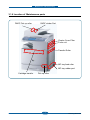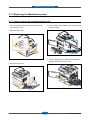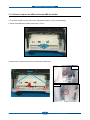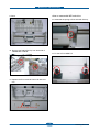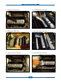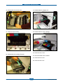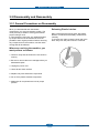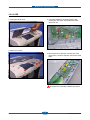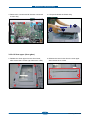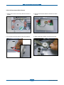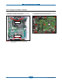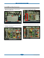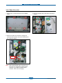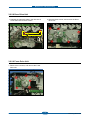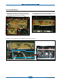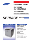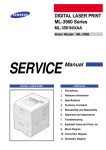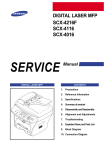
1
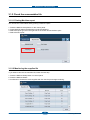
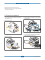
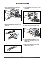
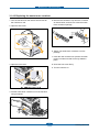
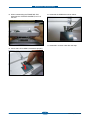
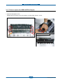
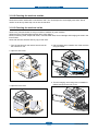
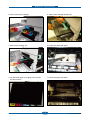
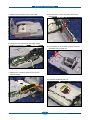
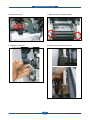
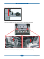
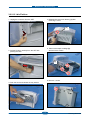
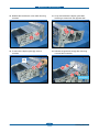
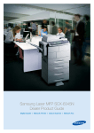
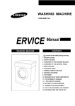
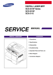
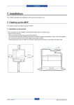
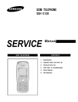
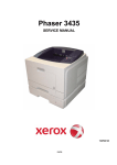
Maintenance and Disassembly
3. Maintenance and Disassembly
Introduction
To avoid print quality and paper feed problems resulting from worn parts and to maintain your
machine in top working condition the following items will need to be replaced after the specified
number of pages or when the life span of each item has expired.
3.1 Maintenance
3.1.1 Precautions on Maintenance
■ Replacing
!
The fuser is very hot. So turn the printer off and wait until the printer to cool before replacing it.
!
To avoid the print quality problems, do not touch the surface of rollers.
(transfer roller, pick up roller, feed roller, Cartridge transfer Unit, Imaging Unit)
■ Cleaning
- Make sure the power cord is unplugged before the cleaning.
- Do not use flammable liquid cleaner or spray products for cleaning.
- Avoid making scratches while cleaning the parts.
- Avoid direct contact by hand on the Transfer Roller.
!
Avoid exposing inner parts for a long duration of time.
!
The surface of OPC drum in Imaging Unit can be affected by direct light if exposed for a long time.
(1~2 minutes is enough time for cleaning)
!
The OPC surface of Imaging Unit and belt surface of Cartridge transfer unit must not be scratched.
Service Manual
3-1
Samsung Electronics
Maintenance and Disassembly
3.1.2 Check the consumables life
3.1.2.1 Printing Machine report
You can see the consumables life by printing a machine report.
1. Press the Machine setup button on the control panel.
2. Press Machine Status>the Machine Info tab>Print/Report
3. Select the report type, then the right side of the screen shows the list to print.
4. Select the list to print.
3.1.2.2 Monitoring the supplies life
If you want to view the consumables life, follow the next step.
1. Press the Machine Setup button on control panel.
2. Press the Machine Status
3. Scroll down to browse the entire supplies with list view the percentage remaining.
Service Manual
3-2
Samsung Electronics
Maintenance and Disassembly
3.1.3 Consumables (CRU : Customer Replacement Unit)
Model Name
Description
Life
CLX-C8385A
Toner Cartridge (Cyan)
15K Pages
CLX-M8385A
Toner Cartridge (Magenta)
15K Pages
CLX-Y8385A
Toner Cartridge (Yellow)
15K Pages
CLX-K8385A
Toner Cartridge (Black)
20K Pages
CLX-R8385C
Imaging Unit (Cyan)
30K Pages
CLX-R8385M
Imaging Unit (Magenta)
30K Pages
CLX-R8385Y
Imaging Unit (Yellow)
30K Pages
CLX-R8385K
Imaging Unit (Black)
30K Pages
CLX-W8380A
Waste toner container
48K Images
Image
Note
• Declared yield value in accordance with ISO/IEC 19798.
For ISO/IEC 19798 standard pages, refer to section 3 of chapter 6.
• Image counts are based on one color on each page. If you print documents in full color (Yellow, Magenta,
Cyan, Black), the image count will be added by 4 images.
Service Manual
3-3
Samsung Electronics
Maintenance and Disassembly
3.1.4 Replacing the Consumables
3.1.4.1 Replacing the toner cartridge
1. Turn the machine off, then wait a few minutes for
the machine to cool.
4. Pull the corresponding toner cartridge out from
the machine.
2. Open the side cover.
5. Remove the new toner cartridge from its bag.
6. Thoroughly roll the new cartridge five or six times
to distribute the toner evenly inside the cartridge.
3. Open the front cover.
7. Hold the new toner cartridge by the handle and
slide the new toner cartridge in until it locks in
place.
Service Manual
3-4
Samsung Electronics
Maintenance and Disassembly
8. Close the front cover, then the side cover.
9. Make sure that the cover is securely latched and
then turn the machine on.
3.1.4.2 Replacing the imaging unit
1. Turn the machine off, then wait a few minutes for
the machine to cool.
4. Pull the waste toner container out of the machine
using its handle.
2. Open the side cover.
5. Turn the imaging unit locking levers outwards to
release and open the inner cover.
3. Open the front cover.
Service Manual
3-5
Samsung Electronics
Maintenance and Disassembly
11. Labels inside the machine identify each imaging
unit’s position.
Holding the handles on the new imaging unit,
push the imaging unit until it locks in place.
6. Pull the used imaging unit out of the machine
using the handle on its bottom.
7. Remove the new imaging unit from its bag.
8. Remove the paper protecting the surface of the
imaging unit.
12. Turn the imaging unit locking levers inwards
until it locks in place and close the inner cover.
9. Remove the cap, and carefully pull the seal
tapes out of the imaging unit.
13. Insert the waste toner container into position
and then push it to make sure that it is firmly
seated in place.
10. Thoroughly shake the new imaging unit side to
side five or six times.
Service Manual
14. Close the front cover, then the side cover.
15. Make sure that the cover is securely latched
and then turn the machine on.
3-6
Samsung Electronics
Maintenance and Disassembly
3.1.4.3 Replacing the waste toner container
1. Turn the machine off, then wait a few minutes for
the machine to cool.
5. Remove the container’s cap from the container
as shown below, and use it to close the waste
toner container openings.
2. Open the side cover.
6. Take a new waste toner container out of its
package.
7. Insert the new container into position and then
push it to make sure that it is firmly seated in
place.
3. Open the front cover.
8. Close the front cover firmly.
9. Turn the machine on.
4. Pull the waste toner container out of the machine
using its handle.
Service Manual
3-7
Samsung Electronics
Maintenance and Disassembly
3.1.5 Maintenance Parts (FRU : Field Replacement Unit)
Sec_Code
Description
Life
JC96-04601A
CARTRIDGE-TRANSFER
(ITB)
100K
JC97-02934A
MEA UNIT-TR
(Transfer roller Assy)
100K
JC96-04867A (110V)
JC96-04868A (220V)
ELA UNIT-FUSER LV
ELA UNIT-FUSER HV
100K
JC97-03097A
MEA-HOLDER ADF
RUBBER
20K
JC97-03099A
MEA-PICK UP
(DADF pick up Assy)
200K
JC97-02260A
MEA UNIT-HOLDER PAD
(MP tray pad Assy)
20K
JC96-03533A
ELA HOU-MP PICK UP
200K
JC97-03269A
MEA UNIT-Exit Duplex
100K
JC97-02259A
MEA UNIT-ROLLER PU
(Pick up roller
Forward roller
Retard roller)
100K
JC90-00956A
DUPLEX-COVER FILTER
100K
Service Manual
3-8
Image
Samsung Electronics
Maintenance and Disassembly
■ Maintenance KIT List
Model code
CLX-V8385A
CLX-V8385A/SEE
CLX-V8385A/XAA
Service Manual
KIT component
Part Code
Qty
CARTRIDGE-TRANSFER (ITB)
MEA UNIT-TR (Transfer roller)
ELA UNIT-FUSER HV (Fuser)
MEA UNIT-EXIT DUPLEX
MEA UNIT-ROLLER PU (Pick up/
Forward/ Retard roller)
DUPLEX-COVER FILTER
JC96-04601A
JC97-02934A
JC96-04868A
JC97-03269A
JC97-02259A
1
1
1
1
3
JC90-00956A
1
CARTRIDGE-TRANSFER (ITB)
MEA UNIT-TR (Transfer roller)
ELA UNIT-FUSER HV (Fuser)
MEA UNIT-EXIT DUPLEX
MEA UNIT-ROLLER PU (Pick up/
Forward/ Retard roller)
DUPLEX-COVER FILTER
JC96-04601A
JC97-02934A
JC96-04868A
JC97-03269A
JC97-02259A
1
1
1
1
3
JC90-00956A
1
CARTRIDGE-TRANSFER (ITB)
MEA UNIT-TR (Transfer roller)
ELA UNIT-FUSER LV (Fuser)
MEA UNIT-EXIT DUPLEX
MEA UNIT-ROLLER PU (Pick up/
Forward/ Retard roller)
DUPLEX-COVER FILTER
JC96-04601A
JC97-02934A
JC96-04867A
JC97-03269A
JC97-02259A
1
1
1
1
3
JC90-00956A
1
3-9
Life time
Remark
100K
100K
Korea
220V
100K
Export
220V
100K
Export
110V
Samsung Electronics
Maintenance and Disassembly
3.1.6 Location of Maintenance parts
DADF Pick up roller
DADF rubber Pad
Duplex Cover Filter
Fuser unit
Transfer Roller
MP tray feed roller
MP tray rubber pad
Cartridge transfer
Service Manual
Pick up roller
3-10
Samsung Electronics
Maintenance and Disassembly
3.1.7 Replacing the Maintenance parts
3.1.7.1 How to replace the cartridge transfer unit
1. Turn the machine off, then wait a few minutes for
the machine to cool.
4. Pull the waste toner container out of the machine
using its handle.
2. Open the side cover.
5. Turn the imaging unit locking levers outwards to
release and open the inner cover.
3. Open the front cover.
Service Manual
3-11
Samsung Electronics
Maintenance and Disassembly
6. Take out the Cartridge transfer unit and replace
the new one.
7. Close the inner cover.
8. Insert the waste toner container.
9. Close the front cover, then the side cover.
3.1.7.2 How to replace the transfer roller
1. Open the side cover and then pull the guidepaper up in the direction of arrow.
Service Manual
2. Push the latch in the two directions and pull the
Transfer roller. And replace the new one.
3-12
Samsung Electronics
Maintenance and Disassembly
3.1.7.3 How to replace the Fuser unit
1. Open the side cover.
Service Manual
2. Pull the Fuser unit by holding the green lever.
And replace the new one
3-13
Samsung Electronics
Maintenance and Disassembly
3.1.7.4 How to replace the DADF pick up roller and rubber pad.
1. Open the DADF Cover.
3. Remove the rubber pad unit.
2. Pull the bush in the direction of arrow. Then lift
the DADF pick up roller out.
Service Manual
3-14
Samsung Electronics
Maintenance and Disassembly
3.1.7.5 How to replace the Pick-up Roller
1. To remove the pick up roller, first take out the cassette. After remove the cassette, you can see 3 rollers
(Pick up/ Forward/ Retard) in the inner.
Forward
Roller
Forward
Roller
Pick
Pick
UpUp
Roller
Roller
Retard
Roller
Retard
Roller
2. Take out the roller after pulling the hinge of pick up roller in the direction of arrow.
22
11
Service Manual
3-15
Samsung Electronics
Maintenance and Disassembly
3.1.7.6 How to replace the MP pad Unit and MP feed roller
1. To remove the MP unit, first remove the side duplex. (Refer to 3.2.2.12 Side duplex)
2. Remove the MP pad unit after remove the 1 screw.
Gear
Bracket
3. Remove the 4 screws and 2 hooks and take out the MP Assy.
Right
Hook
Right
Hook
Left
Left
Service Manual
3-16
Samsung Electronics
ELA HOU-MP
Maintenance and Disassembly
ELA HOU-MP
ELA
4. Done.
ELA HOU-MP
HOU-MP
ELA HOU-MP
MEA UNIT-HOLDER PAD
MEA UNIT-HOLDER PAD
MEA
MEA UNIT-HOLDER
UNIT-HOLDER PAD
PAD
MEA UNIT-HOLDER PAD
<How to replace the MP feed roller>
7. Remove the 4 screws from both side of MP unit.
5. Release the harness from the holder.
6. Remove the spring from hook with some tools.
8. Lift up the FRAME-MP TOP.
Service Manual
3-17
Samsung Electronics
Maintenance and Disassembly
ELA-
HOU MP PICK- UP
<How to reassemble MP feed roller>
9. Done.
12. Assemble the spring to ELA HOU-MP Pick up.
ELAELA-HOU
HOUMP
MPPICKPICK-UP
UP
10. Remove the RING-E(2 EA) from both side of
FRAME-MP LOWER.
13. Fix the LATCH ARM F,R.
11. Replace the ELA-HOU MP PICK-UP with new
one.
ELA- HOU MP PICK- UP
Service Manual
3-18
Samsung Electronics
Maintenance and Disassembly
14. When reassembling the FRAME-MP TOP,
assemble the STOPPER PAPER F,R to be in
the hole.
16. Assemble the SPRING as shown below.
17. Assemble in reverse order after this step.
15. Check that LATCH ARM F,R assemble properly.
Service Manual
3-19
Samsung Electronics
Maintenance and Disassembly
3.1.7.7 How to replace the MEA UNIT-Exit Duplex
1. Open the side duplex cover.
Release the Exit Duplex Unit by removing the 4 hooks after remove 1 screw.
MEA UNIT-EXIT DUPLEX
Service Manual
3-20
Samsung Electronics
Maintenance and Disassembly
3.1.7.8 How to replace the DUPLEX-COVER FILTER
1. Open the side duplex cover. And press the hook as shown below.
2. Release the duplex-cover filter.
Service Manual
3-21
Samsung Electronics
Maintenance and Disassembly
3.1.8 Cleaning the machine
To maintain print and scan quality, follow the cleaning procedures below
each time the toner cartridge is replaced or if print and scan quality problems occur.
Caution
• Cleaning the machine cabinet with cleaning materials that contain large amounts of alcohol, solvent, or
other strong substances can discolor or damage the cabinet.
• If your machine or its surrounding is contaminated with toner, we recommend you to use cloth or tissue
dampened with water to clean it. If you use a vacuum cleaner, toner blows in the air and might be harmful
to you.
3.1.8.1 Cleaning Items and Interval
Item
Interval or When
Replacement consumable
(Toner Cartridges, Imaging Units, WTB )
When displayed “Toner Empty” or “Replace Drum” or
“Waste Toner Full” .
Cleaning of Feed frame and Feed Rollers on
the paper-path
Misfeeds or Jams occur frequently
Cleaning of Document (Platen) glass
Cleaning of Platen Cover (sheet-sponge)
Cleaning Feeder and PAD in the DADF
Cleaning of LSU glass
Cleaning of Document glass for DADF
The same copy area is dirty whenever making copies.
Original cannot be cleanly scanned.
Originals have black streaks or appear dirty after feeding
them in the DADF.
Streaks appear on copy sheet
Cleaning of original guide plate in rear side of
DADF and DADF roller
Misfeeds or Jams occur frequently
Fasten the rest of the guide in the paper tray
(Width Guide and Length Guide)
Misfeeds or Jams occur frequently
Pick up a stack/tray of paper and fan it to
remove static cling
Multi-feeds occur frequently
Replace the Transfer roller
Image ghost, Light image, paper’s rear side contamination
occur.
Service Manual
3-22
Samsung Electronics
Maintenance and Disassembly
3.1.8.2 Cleaning the machine outside
Clean the machine cabinet with a soft lint-free cloth. You can dampen the cloth slightly with water, but be
careful not to let any water drip onto or into the machine.
3.1.8.3 Cleaning the machine inside
Clean every 100,000 sheets or every 6 months to maintain in good condition.
(When the life of Transfer Roller expires due to long usage.)
Clean in following order; Paper Path Parts, Transfer Roller area, Toner Cartridge and Imaging unit area in the
Inner Frame.
Clean with Vacuum Cleaner and Dry rag or Soft cloth.
1. Turn the machine off, then wait a few minutes for
the machine to cool.
4. Pull the waste toner container out of the machine
using its handle.
2. Open the side cover.
5. Turn the imaging unit locking levers outwards to
release and open the inner cover.
3. Open the front cover.
Service Manual
3-23
Samsung Electronics
Maintenance and Disassembly
6. Take out the toner cartridge.
9. Take out the cartridge transfer unit.
7. Take out the Imaging unit.
10. Clean the paper path parts.
8. Lay the black paper on imaging unit to protect
the OPC surface.
11. Clean the paper path parts.
Service Manual
3-24
Samsung Electronics
Maintenance and Disassembly
12. Clean the paper path parts.
15. Clean the transfer roller area.
13. Release the transfer roller.
16. Clean the transfer roller area.
14. Clean the transfer roller area.
17. Clean the transfer roller area.
Service Manual
3-25
Samsung Electronics
Maintenance and Disassembly
18. Reassemble the transfer roller.
21. Reassemble the imaging unit.
19. Clean the Frame inside.
22. Reassemble the toner cartridge.
23. Close the inner cover.
20. Reassemble the Cartridge Transfer.
24. Insert the waste toner container.
25. Close the front cover.
26. Close the side cover.
Service Manual
3-26
Samsung Electronics
Maintenance and Disassembly
3.1.8.4 Cleaning the scan outside glass
Keeping the scan unit clean helps ensure the best possible copies. We suggest that you clean the scan unit
at the start of each day and during the day, as needed.
1 Slightly dampen a soft lint-free cloth or paper towel with water.
2 Open the scanner lid.
3 Wipe the surface of the scanner glass and DADF glass until it is clean and dry.
4. Wipe the underside of the scanner lid until it is clean and dry.
5. Close the scanner lid.
3.1.8.5 Cleaning the scan inside glass
1. Perform the procedure 1~6 of 3.2.2.4 Scan Assy.
2. Wipe the surface of the scan inside glass.
3. Reassemble the Scan Assy.
Service Manual
3-27
Samsung Electronics
Maintenance and Disassembly
3.2 Disassembly and Reassembly
3.2.1 General Precautions on Disassembly
Releasing Plastic Latches
When you disassemble and reassemble
components, you must use extreme caution. The
close proximity of cables to moving parts makes
proper routing a must.
If components are removed, any cables disturbed
by the procedure must be restored as close as
possible to their original positions. Before removing
any component from the machine, note the cable
routing that will be affected.
Many of the parts are held in place with plastic
latches. The latches break easily; release them
carefully.
To remove such parts, press the hook end of the
latch away from the part to which it is latched.
Whenever servicing the machine, you
must perform as follows:
1. Check to verify that documents are not stored in
memory.
2. Be sure to remove the toner cartridge before you
disassemble parts.
3. Unplug the power cord.
4. Use a flat and clean surface.
5. Replace only with authorized components.
6. Do not force plastic-material components.
7. Make sure all components are in their proper
position.
Service Manual
3-28
Samsung Electronics
Maintenance and Disassembly
3.2.1.1 Screws used in the printer
Part_Code
Location
Description
Qty
6003-000282 ELA UNIT-LSU
SCREW-TAPTITE;BH,+,-,B,M3,L8,ZPC(BLK),SWRCH18A,-
20
6003-000282 ELA UNIT-LD_Y
SCREW-TAPTITE;BH,+,-,B,M3,L8,ZPC(BLK),SWRCH18A,-
2
6001-000130
SCREW-MACHINE;BH,+,M3,L6,ZPC(WHT),SWRCH18A,-,-
2
6003-000196 DUPLEX
SCREW-TAPTITE;PWH,+,B,M3,L10,NI PLT,SWRCH18A
23
6003-000269
SCREW-TAPTITE;BH,+,-,S,M3,L6,ZPC(WHT),SWRCH18A,-
2
SCREW-TAPPING;PWH,+,-,2,M3,L8,ZPC(BLK),SWRCH18A,-
4
SCREW-TAPTITE;PWH,+,B,M3,L10,NI PLT,SWRCH18A
5
6003-000264 MEA UNIT-TRAY
SCREW-TAPTITE;PWH,+,-,B,M3,L6,ZPC(WHT),SWRCH18A,-
1
6003-000196 MEA UNIT-EXIT DUPLEX
SCREW-TAPTITE;PWH,+,B,M3,L10,NI PLT,SWRCH18A
1
6003-000196
SCREW-TAPTITE;PWH,+,B,M3,L10,NI PLT,SWRCH18A
9
SCREW-TAPTITE;BH,+,-,S,M3,L6,ZPC(WHT),SWRCH18A,-
2
SCREW-TAPTITE;BH,+,B,M4,L10,NI PLT,SWRCH18A
5
6009-001492
SCREW-HEX;HWH,+,M3,L8,NI PLT,SWRCH18A,S,RF
9
6003-000196
SCREW-TAPTITE;PWH,+,B,M3,L10,NI PLT,SWRCH18A
13
6003-000269
SCREW-TAPTITE;BH,+,-,S,M3,L6,ZPC(WHT),SWRCH18A,-
11
SCREW-TAPTITE;BH,+,-,S,M4,L6,ZPC(WHT),SWRCH18A,-
1
SCREW-TAPTITE;BH,+,B,M4,L10,NI PLT,SWRCH18A
7
6009-001396
SCREW-SPECIAL;PH,+,-,M3,L10.3,ZPC(BLK),SWRCH18A,B
TITE,-
2
6003-000282 ELA UNIT-SIZE SENSOR
SCREW-TAPTITE;BH,+,-,B,M3,L8,ZPC(BLK),SWRCH18A,-
2
6003-000266 ELA UNIT-CST SENSOR
SCREW-TAPTITE;PWH,+,-,S,M3,L6,ZPC(WHT),SWRCH18A,-
2
6003-000269
SCREW-TAPTITE;BH,+,-,S,M3,L6,ZPC(WHT),SWRCH18A,-
13
SCREW-TAPTITE;BH,+,-,B,M3,L30,ZPC(WHT),SWRCH18A,-
3
SCREW-TAPTITE;PWH,+,B,M3,L10,NI PLT,SWRCH18A
3
SCREW-TAPTITE;BH,+,-,S,M3,L6,ZPC(WHT),SWRCH18A,-
6
6003-000196 ELA HOU-MP
SCREW-TAPTITE;PWH,+,B,M3,L10,NI PLT,SWRCH18A
4
6003-000196 ELA UNIT-BASE RIGHT
SCREW-TAPTITE;PWH,+,B,M3,L10,NI PLT,SWRCH18A
6
6003-000269 MEA UNIT-RETARD
SCREW-TAPTITE;BH,+,-,S,M3,L6,ZPC(WHT),SWRCH18A,-
2
6003-000196
SCREW-TAPTITE;PWH,+,B,M3,L10,NI PLT,SWRCH18A
87
SCREW-TAPTITE;BH,+,-,S,M3,L6,ZPC(WHT),SWRCH18A,-
4
6003-000196 ELA UNIT-HV ITB
SCREW-TAPTITE;PWH,+,B,M3,L10,NI PLT,SWRCH18A
4
6003-000269 ELA UNIT-WTB MOTOR
SCREW-TAPTITE;BH,+,-,S,M3,L6,ZPC(WHT),SWRCH18A,-
2
6003-000269 ELA UNIT-HOLDER OPC
SCREW-TAPTITE;BH,+,-,S,M3,L6,ZPC(WHT),SWRCH18A,-
11
6003-000196 ELA UNIT-HV TR
SCREW-TAPTITE;PWH,+,B,M3,L10,NI PLT,SWRCH18A
2
6003-000196 ELA HOU-BOTTLE BASE
SCREW-TAPTITE;PWH,+,B,M3,L10,NI PLT,SWRCH18A
13
6003-000196 ELA UNIT-HV DEVE
SCREW-TAPTITE;PWH,+,B,M3,L10,NI PLT,SWRCH18A
8
6002-000440
6003-000196
6003-000269
6003-001256
6003-000301
6003-001256
6003-001474
6003-000196
6003-000269
6003-000269
Service Manual
ELA HOU-DUPLEX
FRAME
ELA UNIT-BASE FRAME
ELA UNIT-BASE PLATE R
ELA UNIT-PLATE UPPER
FRMAE-LOWER
3-29
Samsung Electronics
Maintenance and Disassembly
Part_Code
Location
Description
Qty
6003-000196 FRAME REGI
SCREW-TAPTITE;PWH,+,B,M3,L10,NI PLT,SWRCH18A
5
6003-000196 ELA HOU-GUIDE REGI
SCREW-TAPTITE;PWH,+,B,M3,L10,NI PLT,SWRCH18A
6
6003-000196 MEA UNIT-F DR
SCREW-TAPTITE;PWH,+,B,M3,L10,NI PLT,SWRCH18A
1
6003-000196 ELA UNIT-FRAME UPPER
SCREW-TAPTITE;PWH,+,B,M3,L10,NI PLT,SWRCH18A
12
6003-000196 ELA HOU-GUIDE EXIT
SCREW-TAPTITE;PWH,+,B,M3,L10,NI PLT,SWRCH18A
2
6003-000269 ELA UNIT-SUPPORT SCAN
SCREW-TAPTITE;BH,+,-,S,M3,L6,ZPC(WHT),SWRCH18A,-
3
6009-001390 ELA UNIT-SCANNER
SCREW-SPECIAL;SPECIAL,±,-,M3,L10,NI
PLT,SWRCH18A,B-TITE,D9, L13.5, DIME
1
6003-000196 ELA UNIT-PLATEN
SCREW-TAPTITE;PWH,+,B,M3,L10,NI PLT,SWRCH18A
6
6003-000196
SCREW-TAPTITE;PWH,+,B,M3,L10,NI PLT,SWRCH18A
13
6003-000269 ELA UNIT-SCAN LOWER
SCREW-TAPTITE;BH,+,-,S,M3,L6,ZPC(WHT),SWRCH18A,-
4
6003-001256
SCREW-TAPTITE;BH,+,B,M4,L10,NI PLT,SWRCH18A
14
6003-000282 ELA UNIT-CCDM HIGH
SCREW-TAPTITE;BH,+,-,B,M3,L8,ZPC(BLK),SWRCH18A,-
10
6003-000282 MEA UNIT-COVER KHX
SCREW-TAPTITE;BH,+,-,B,M3,L8,ZPC(BLK),SWRCH18A,-
3
6003-000269 ELA UNIT-SCAN MOTOR
SCREW-TAPTITE;BH,+,-,S,M3,L6,ZPC(WHT),SWRCH18A,-
2
6002-000440
SCREW-TAPPING;PWH,+,-,2,M3,L8,ZPC(BLK),SWRCH18A,-
2
SCREW-TAPTITE;PWH,+,B,M3,L10,NI PLT,SWRCH18A
2
6003-000196 MEA UNIT-DUMMY UPPER
SCREW-TAPTITE;PWH,+,B,M3,L10,NI PLT,SWRCH18A
1
6003-000196
SCREW-TAPTITE;PWH,+,B,M3,L10,NI PLT,SWRCH18A
7
6003-000269 ELA HOU-DADF
SCREW-TAPTITE;BH,+,-,S,M3,L6,ZPC(WHT),SWRCH18A,-
8
6003-001256
SCREW-TAPTITE;BH,+,B,M4,L10,NI PLT,SWRCH18A
5
SCREW-TAPTITE;PWH,+,B,M3,L10,NI PLT,SWRCH18A
14
SCREW-TAPTITE;BH,+,B,M4,L16,NI PLT,SWRCH18A,-
8
6003-000196 ELA HOU-COVER JAM
SCREW-TAPTITE;PWH,+,B,M3,L10,NI PLT,SWRCH18A
1
6003-000196
SCREW-TAPTITE;PWH,+,B,M3,L10,NI PLT,SWRCH18A
14
SCREW-TAPTITE;BH,+,-,S,M3,L6,ZPC(WHT),SWRCH18A,-
1
6003-000269 ELA HOU-DADF MOTOR
SCREW-TAPTITE;BH,+,-,S,M3,L6,ZPC(WHT),SWRCH18A,-
4
6003-000269 ELA HOU-DUPLEX MOTOR
SCREW-TAPTITE;BH,+,-,S,M3,L6,ZPC(WHT),SWRCH18A,-
2
6002-000440
SCREW-TAPPING;PWH,+,-,2,M3,L8,ZPC(BLK),SWRCH18A,-
2
6003-000196 ELA HOU-GUIDE SCAN
SCREW-TAPTITE;PWH,+,B,M3,L10,NI PLT,SWRCH18A
7
6003-000269
SCREW-TAPTITE;BH,+,-,S,M3,L6,ZPC(WHT),SWRCH18A,-
1
6003-000196 ELA HOU-COVER OPEN
SCREW-TAPTITE;PWH,+,B,M3,L10,NI PLT,SWRCH18A
5
6003-000196 MEA-EXIT
SCREW-TAPTITE;PWH,+,B,M3,L10,NI PLT,SWRCH18A
2
6003-000196 MEA-GUIDE PICKUP
SCREW-TAPTITE;PWH,+,B,M3,L10,NI PLT,SWRCH18A
4
6002-000440
SCREW-TAPPING;PWH,+,-,2,M3,L8,ZPC(BLK),SWRCH18A,-
2
SCREW-TAPTITE;PWH,+,B,M3,L10,NI PLT,SWRCH18A
3
SCREW-TAPTITE;BH,+,-,S,M3,L6,ZPC(WHT),SWRCH18A,-
10
SCREW-TAPTITE;BH,+,-,S,M4,L6,ZPC(WHT),SWRCH18A,-
10
6003-000196
6003-000196
6003-001324
6003-000269
6003-000196
6003-000269
6003-000301
Service Manual
ELA UNIT-SCAN UPPER
ELA HOU-COVER PLATEN
ELA HOU-DADF SUB
MEA-TX STACKER
DRIVE MAIN
3-30
Samsung Electronics
Maintenance and Disassembly
Part_Code
6003-000269
Location
Description
Qty
SCREW-TAPTITE;BH,+,-,S,M3,L6,ZPC(WHT),SWRCH18A,-
16
SCREW-TAPTITE;BH,+,-,S,M4,L6,ZPC(WHT),SWRCH18A,-
17
SCREW-TAPTITE;BH,+,-,S,M3,L6,ZPC(WHT),SWRCH18A,-
4
SCREW-TAPTITE;BH,+,-,S,M4,L6,ZPC(WHT),SWRCH18A,-
4
6003-000282 CARTRIDGE-TRANSFER
SCREW-TAPTITE;BH,+,-,B,M3,L8,ZPC(BLK),SWRCH18A,-
20
6003-000196
SCREW-TAPTITE;PWH,+,B,M3,L10,NI PLT,SWRCH18A
68
6003-000269
SCREW-TAPTITE;BH,+,-,S,M3,L6,ZPC(WHT),SWRCH18A,-
43
6003-001256
SCREW-TAPTITE;BH,+,B,M4,L10,NI PLT,SWRCH18A
22
SCREW-SPECIAL;SPECIAL,±,-,M3,L10,NI
PLT,SWRCH18A,B-TITE,D9, L13.5, DIME
4
SCREW-SPECIAL;PH,+,-,M3,L10.3,ZPC(BLK),SWRCH18A,B
TITE,-
4
SCREW-TAPTITE;PWH,+,B,M3,L10,NI PLT,SWRCH18A
15
SCREW-TAPTITE;BH,+,-,S,M3,L6,ZPC(WHT),SWRCH18A,-
2
SCREW-TAPTITE;PWH,+,B,M3,L10,NI PLT,SWRCH18A
1
SCREW-TAPTITE;BH,+,-,S,M3,L6,ZPC(WHT),SWRCH18A,-
2
6003-000196 ELA UNIT-HOLDER_HVPS
SCREW-TAPTITE;PWH,+,B,M3,L10,NI PLT,SWRCH18A
2
6003-000269 ELA UNIT-SUPPORT REAR
SCREW-TAPTITE;BH,+,-,S,M3,L6,ZPC(WHT),SWRCH18A,-
2
6003-000282 CARTRIDGE-DRUM Y KIT
SCREW-TAPTITE;BH,+,-,B,M3,L8,ZPC(BLK),SWRCH18A,-
7
6001-000130
SCREW-MACHINE;BH,+,M3,L6,ZPC(WHT),SWRCH18A,-,-
2
SCREW-TAPTITE;BH,+,-,B,M3,L8,ZPC(BLK),SWRCH18A,-
5
SCREW-MACHINE;PH,+,WSP,M3,10,ZPC(WHT),SWRCH18
A,-,WD8,TEMPERED
2
SCREW-TAPTITE;BH,+,-,B,M3,L8,ZPC(BLK),SWRCH18A,-
2
6003-000282 CARTRIDGE-DRUM M KIT
SCREW-TAPTITE;BH,+,-,B,M3,L8,ZPC(BLK),SWRCH18A,-
7
6001-000130
SCREW-MACHINE;BH,+,M3,L6,ZPC(WHT),SWRCH18A,-,-
2
SCREW-TAPTITE;BH,+,-,B,M3,L8,ZPC(BLK),SWRCH18A,-
5
SCREW-MACHINE;PH,+,WSP,M3,10,ZPC(WHT),SWRCH18
A,-,WD8,TEMPERED
2
SCREW-TAPTITE;BH,+,-,B,M3,L8,ZPC(BLK),SWRCH18A,-
2
6003-000282 CARTRIDGE-DRUM C KIT
SCREW-TAPTITE;BH,+,-,B,M3,L8,ZPC(BLK),SWRCH18A,-
7
6001-000130
SCREW-MACHINE;BH,+,M3,L6,ZPC(WHT),SWRCH18A,-,-
2
SCREW-TAPTITE;BH,+,-,B,M3,L8,ZPC(BLK),SWRCH18A,-
5
SCREW-MACHINE;PH,+,WSP,M3,10,ZPC(WHT),SWRCH18
A,-,WD8,TEMPERED
2
SCREW-TAPTITE;BH,+,-,B,M3,L8,ZPC(BLK),SWRCH18A,-
2
6003-000301
6003-000269
6003-000301
6009-001390
DRIVE-DEVE
ELA UNIT-DRIVE FUSER
MAINLINE
6009-001396
6003-000196
6003-000269
6003-000196
6003-000269
6003-000282
ELA HOU-EXIT
ELA UNIT-SMPS UPPER
ELA HOU-DEVE UNIT
6006-001193
6003-000282
6003-000282
CARTRIDGE-SUB OPC
CART
ELA HOU-DEVE UNIT
6006-001193
6003-000282
6003-000282
CARTRIDGE-SUB OPC
CART
ELA HOU-DEVE UNIT
6006-001193
6003-000282
Service Manual
CARTRIDGE-SUB OPC
CART
3-31
Samsung Electronics
Maintenance and Disassembly
Part_Code
Location
Description
Qty
6003-000282 CARTRIDGE-DRUM K KIT
SCREW-TAPTITE;BH,+,-,B,M3,L8,ZPC(BLK),SWRCH18A,-
7
6001-000130
SCREW-MACHINE;BH,+,M3,L6,ZPC(WHT),SWRCH18A,-,-
2
SCREW-TAPTITE;BH,+,-,B,M3,L8,ZPC(BLK),SWRCH18A,-
5
6006-001193
SCREW-MACHINE;PH,+,WSP,M3,10,ZPC(WHT),SWRCH18
A,-,WD8,TEMPERED
2
6003-000282 MEA UNIT-OPC CART
SCREW-TAPTITE;BH,+,-,B,M3,L8,ZPC(BLK),SWRCH18A,-
2
6003-000261
SCREW-TAPTITE;BH,+,-,B,M3,L6,ZPC(WHT),SWRCH18A,-
2
SCREW-TAPTITE;BH,+,-,B,M3,L8,ZPC(BLK),SWRCH18A,-
1
SCREW-TAPTITE;BH,+,-,B,M3,L6,ZPC(WHT),SWRCH18A,-
2
SCREW-TAPTITE;BH,+,-,B,M3,L8,ZPC(BLK),SWRCH18A,-
2
SCREW-TAPTITE;BH,+,-,B,M3,L6,ZPC(WHT),SWRCH18A,-
2
SCREW-TAPTITE;BH,+,-,B,M3,L8,ZPC(BLK),SWRCH18A,-
2
SCREW-TAPTITE;BH,+,-,B,M3,L6,ZPC(WHT),SWRCH18A,-
2
SCREW-TAPTITE;BH,+,-,B,M3,L8,ZPC(BLK),SWRCH18A,-
2
SCREW-TAPTITE;PWH,+,B,M3,L10,NI PLT,SWRCH18A
10
SCREW-TAPTITE;BH,+,-,S,M3,L6,ZPC(WHT),SWRCH18A,-
4
6003-000196 ELA HOU-OPE COVER
SCREW-TAPTITE;PWH,+,B,M3,L10,NI PLT,SWRCH18A
7
6002-000440
SCREW-TAPPING;PWH,+,-,2,M3,L8,ZPC(BLK),SWRCH18A,-
3
SCREW-TAPTITE;PWH,+,B,M3,L10,NI PLT,SWRCH18A
17
SCREW-TAPTITE;BH,+,-,S,M3,L6,ZPC(WHT),SWRCH18A,-
9
6003-001086
SCREW-TAPTITE;BH,+,-,B,M3,L12,ZPC(BLK),SWRCH18A,-
2
6002-000440
SCREW-TAPPING;PWH,+,-,2,M3,L8,ZPC(BLK),SWRCH18A,-
5
SCREW-TAPTITE;PWH,+,B,M3,L10,NI PLT,SWRCH18A
6
6006-001193
SCREW-MACHINE;PH,+,WSP,M3,10,ZPC(WHT),SWRCH18
A,-,WD8,TEMPERED
1
6002-000440 MEA UNIT-LIFTING GEAR
SCREW-TAPPING;PWH,+,-,2,M3,L8,ZPC(BLK),SWRCH18A,-
2
6003-001001 MEA UNIT-COVER FRONT
SCREW-TAPTITE;FH,+,B,M3,L8,ZPC(BLK),SWRCH18A
2
6002-000440
SCREW-TAPPING;PWH,+,-,2,M3,L8,ZPC(BLK),SWRCH18A,-
6
SCREW-TAPTITE;PWH,+,B,M3,L10,NI PLT,SWRCH18A
4
SCREW-TAPPING;PWH,+,-,2,M3,L8,ZPC(BLK),SWRCH18A,-
30
SCREW-TAPTITE;PH,+,WSP,B,M3,L10,ZPC(WHT),SWRCH1
8A,-
12
6003-000282
6003-000282
6003-000261
6003-000282
6003-000261
6003-000282
6003-000261
6003-000282
6003-000196
6003-000269
6003-000196
6003-000269
6003-000196
6003-000196
ELA HOU-DEVE UNIT
CARTRIDGE-TONER K KIT
ELA UNIT-TONER Y
CARTRIDGE-TONER M KIT
ELA UNIT-TONER C
ELA HOU-OPE
ELA UNIT-FUSER LV
MEA UNIT-CASSETTE
MEA UNIT-COVER INNER
6002-000440
6006-001078
Service Manual
MEA UNIT-FRONT OPC
3-32
Samsung Electronics
Maintenance and Disassembly
3.2.2 General Disassembly
3.2.2.1 Cover
1. Remove the 10 screws from the rear of SET.
4. Remove the Cover rear and the Cover rear
lower.
2. Remove the 4 screws from the left side of SET.
And remove the Cover Panel MFP.
5. Remove the 2 screws and then remove the Unit
Cover Top.
M3X10
M3X10
M3X10
M3X10
M4X10
M4X10
M4X10
M4X10
M3X10
M3X10
M3X10
M3X10
M4X10
M4X10
M4X10
M4X10
3. Remove the COVER-PANEL MFP.
Note : In case of being installed the fax kit, remove the fax kit after
remove the 2 screws.
Service Manual
3-33
Samsung Electronics
Maintenance and Disassembly
6. Open the Side Duplex Cover and the Front cover. And then remove the left side cover.
SIDE-DUPLEX COVER
COVERSIDE LEFT
Service Manual
COVER-FRONT
3-34
Samsung Electronics
Maintenance and Disassembly
3.2.2.2 DADF
1. Remove 3 screws, and disassemble the cover.
3. Open the DADF cover, and remove the one
screw.
2. Separate bracket by using a tool such as
tweezers.
Uplug the connector. And lift up the DADF from
the Platen.
Service Manual
4. Lift up the stacker, and remove the two screws.
3-35
Samsung Electronics
Maintenance and Disassembly
5. Remove the front/rear cover of the DADF.
8. Remove the 3 screws, and then remove the
DADF board.
6. Unplug the all harness from the DADF board.
9. Pull the bush in the direction of arrow. Then lift
the DADF pick up roller out.
7. Remove the 2 screws, and then remove the
harness holder.
10. Remove the DADF pad unit.
Service Manual
3-36
Samsung Electronics
Maintenance and Disassembly
3.2.2.3 OPE
1. Pull up the OPE cover.
3. Lift up the OPE assy as shown below, and
Unplug the connector. And release the OPE
assy from set.
2. Remove 3 screws.
4. Disconnect the 2 harness, 3 flexible pcb, and
remove the 4 screws. And then remove the OPE
PBA.
!
Service Manual
3-37
Be careful not to break the flexible pcb locker.
Samsung Electronics
Maintenance and Disassembly
5. To remove the LCD panel, remove the 10 screws. Take out the LCD panel after remove the LCD panel
shield.
3.2.2.4 Scan Ass’y
3.2.2.4.1 Platen Ass’y
1. Remove the 2 screws from the Front dummy
cover and release it.
2
Service Manual
3
1
2. Remove the 4 screws from front-down side of
scan assy.
3-38
Samsung Electronics
Maintenance and Disassembly
3. Remove the 3 screws and all harness connected
to scan assy.
4. Lift up and release the Platen Assy.
2
3
1
3.2.2.4.2 Scan upper (Scan glass)
1. R
elease the Scan upper from the Scan lower
after remove the 6 screws (cap hole screw 3 EA)
Service Manual
2. Release the Lever-locker from the scan upper
after remove the 2 screws.
3-39
Samsung Electronics
Maintenance and Disassembly
3.2.2.4.3 CCD module
1. To remove the CCD harness, first remove the
sheet.
3. Remove the CCDM after remove the CCDM
belt.
2. Unplug the FFC cable and power cable.
Service Manual
3-40
Samsung Electronics
Maintenance and Disassembly
3.2.2.4.4 Scan motor, Belt, Sensor
1. Remove the Scan motor assy after remove the 4
screws.
3. Remove the screws and the harness from each
sensor.
2. To remove the CCD harness, remove the sheet.
4. When replacing the Belt, compress the spring.
Service Manual
3-41
Samsung Electronics
Maintenance and Disassembly
3.2.2.5 Engine and Video controller
1. Unplug the all harness and remove the 4 screws
from Video controller. And release it.
2. Unplug the all harness and remove the 9 screws
from Engine controller. And release it.
S3X6
M3X10
Caution - When reassembling, be careful the
screw type.
Service Manual
3-42
Samsung Electronics
Maintenance and Disassembly
3.2.2.6 SMPS and Fuser Drive board
1. Remove the 3 screws and 1 connector (FAN).
Remove the SMPS cover.
3. Remove the all harness from SMPS.
4. Remove the SMPS after remove the 8 screws.
2. Unplug the all harness and remove the 4 screws
from FDB . And release it.
Service Manual
3-43
Samsung Electronics
Maintenance and Disassembly
3.2.2.7 Main Drive Unit
1. Remove the 4 screws and remove the SMPS
cover.
3. Remove the Main Drive Unit after removing 6
screws.
Fixer
2. Remove 3 fixers from clutches. Unplug one
connector and remove one screw. And remove
the 3 clutches below.
Fixer
Note : W
hen disassembling the main drive unit,
Don’t have to unplug the 3 below clutch
harness. If you want to replace these
clutches, refer to the next page.
Service Manual
3-44
Samsung Electronics
Maintenance and Disassembly
< How to replace the cluch >
1. Hold the harness with the nipper.
2. Unplug the harness as shown below.
Caution - Don’t grip with force. It is easy to
disconnect.
※ Precautions
1. When reassembling the 2 clutch below, check the harness color.
There is the incuse on the shield. B/B means black/black harness, G/B means gary/black harness.
Service Manual
3-45
Samsung Electronics
Maintenance and Disassembly
3.2.2.8 Deve Drive Unit
1. Release the harness holder in the direction of
arrow after remove the 2 screws.
2. Remove the 6 screws, and remove the Deve
Drive unit.
3.2.2.9 Fuser Drive Unit
1. Remove the 6 screws, and remove the Fuser
Drive unit.
Service Manual
3-46
Samsung Electronics
Maintenance and Disassembly
3.2.2.10 HVPS Board
1. Remove the left side cover. (Refer to 3.2 Cover)
Unplug the all connector from HVPS(L). Remove
the HVPS(L) after remove the 9 screws.
3. Unplug the all connector from HVPS(S). Remove
the HVPS(S) after remove the 5 screws.
2. Remove the HVPS holder and FAN after remove the 3 screws.
Service Manual
3-47
Samsung Electronics
Maintenance and Disassembly
3.2.2.11 LSU
1. To remove the LSU unit, first remove the left
side cover and HVPS board. Remove the all
connector as shown below. And remove the LSU
pusher unit after remove the one screws.
2. Take out the LSU unit.
LSU
LSU
Service Manual
3-48
Samsung Electronics
Maintenance and Disassembly
3.2.2.12 Side Duplex
1. Remove the cover rear. (Refer to 3.2.2.1 Cover)
3. Cut the cable tie.
4. Remove the mold E-Ring and clutch.
2. Find the sensor harness and unplug it.
Service Manual
3-49
Samsung Electronics
Maintenance and Disassembly
5. Remove 2 screws.
7. Open the side cover (Side duplex).
6. Unplug the connector.
8. Release the holder from both side.
Service Manual
3-50
Samsung Electronics
Maintenance and Disassembly
Caution - Don’t open the side cover over a right angle.
9. Lift up the side duplex to remove the hook from both side. And release the side duplex.
Caution - When reassembling the side duplex, please check that both hook is put properly.
Service Manual
3-51
Samsung Electronics
Maintenance and Disassembly
3.2.2.13 1-bin Finisher
1. Unplug the connector from the SET.
4. Release the cover scan dummy [A] after
removing 1 screw.
[A]
[A]
[A]
[A]
[A]
[A]
5. Take out the staple cartridge [B].
And remove 3 screws.
2. Pull the Finisher carefully from the SET with
pushing the latch.
[B]
[B]
[B]
[B]
[B]
[B]
6. Remove 1 screw.
3. Push the hook and release the tray stacker.
Service Manual
3-52
Samsung Electronics
Maintenance and Disassembly
7. Release the front cover [C].
10. Release the rear cover.
[C]
[C]
[C]
[C]
[C]
[C]
[D]
[D]
[D]
[D]
[D]
[D]
8. To remove the rear cover, remove 1 screw.
11. To remove the top cover, remove 2 screws.
9. Remove 1 screw.
12. Release the top cover [E] after removing
2 screws.
[E]
[E]
[E]
[E]
[E]
[E]
Service Manual
3-53
Samsung Electronics
Maintenance and Disassembly
13. Release the paddle [F].
16. To remove the finisher main PBA, remove 2
screws.
[F]
[F]
[F]
[F]
[F]
[F]
14. To remove the stay stacker, remove 2 screws.
17. Remove 2 screws.
15. Release the stay stacker after removing 2
screws.
Service Manual
18. Lift the shield stacker up and unplug the
connector.
3-54
Samsung Electronics
Maintenance and Disassembly
19. Unplug all connector on board. Remove 3
screws and 3 fixer. And release the PBA.
22. Unplug 2 connectors. Remove 3 screws.
And release the stapler unit.
20. To remove the Finisher connector, remove 2
screws.
23. Remove 2 screw. Unplug the connector.
And remove the motor unit.
21. Release the finisher connector after removing 1
screw.
24. Release the bracket rear cover after removing
2 screws.
[G]
[G]
[G]
[G]
Service Manual
3-55
Samsung Electronics
Maintenance and Disassembly
25. Release the bracket rear cover after removing
2 screws.
27. Lift up and release the duplex guide after
removing 3 screws from the opposite side.
[I]
[I]
Connector
Connector
26. To remove the duplex guide [H], remove
3 screws.
28. Release the guide exit unit [I] after removing
4 screws and connector.
[H]
[H]
[I]
Connector
[H]
Service Manual
3-56
Samsung Electronics
Maintenance and Disassembly
3.2.2.14 Mail box
1. Lift up Mail box Unit.
4. Remove the front cover. Separate the rear cover
after remove the harness.
2. Remove the Stacker. (4 ea)
5. Remove the jam cover.
3. Remove 2 screws to separate front/rear cover.
Service Manual
3-57
Samsung Electronics
Maintenance and Disassembly
6. Remove the top cover after remove 4 screws.
8. To remove the Motor, remove 4 screws and 4
harness.
Top cover
Top cover
Top cover
Top cover
9. Remove the 2 SPUR Gear after remove screw.
7. pen the Assy Shiled TOP. If necessary, remove
switch or sensor.
Caution
When re-assembling, align the groove of both gear.
Service Manual
3-58
Samsung Electronics
Maintenance and Disassembly
10. Separate the bracket and main board after
remove 5 screws.
13. Remove 2 screws (green color) from the rear.
14. Remove the ROLLER:STACKER.
11. Remove the SPUR Gear after remove screw.
15. Remove the SEPARATE:PAWL:FEED by
unhooking the side.
12. There are 3 Assy actuator shield. This manual
describes disassembly procedure for middle
shield. Remove 2 screws (green color) from the
front.
Service Manual
3-59
Samsung Electronics
Maintenance and Disassembly
16. Push the Assy actuator shield to the direction of
arrow. And Separate it from the opposite side.
Service Manual
17. Done
3-60
Samsung Electronics
Maintenance and Disassembly
3.2.2.15 2-Bin Finisher
1. Unplug the connector.
3. Remove the staple cartridge.
2. Keep the 1c lever pull up and remove the
finisher unit from the SET.
4. To remove the cover, remove the 2 screws.
Top view
Top view
Top
Top view
view
To
Bottom view
Bottom view
Bottom
Bottom view
view
Service Manual
3-61
Bo
Samsung Electronics
Maintenance and Disassembly
5. Remove the 3 screws.
7. Remove the 3 screws and take off the cover.
6. If some part such as sensor, switch in below
picture is defective, replace it.
8. If some part in below picture is defective, replace
it.
Service Manual
3-62
Samsung Electronics
Maintenance and Disassembly
9. Remove the 4 screws from both side.
10. Open the cover and unplug the connector.
Service Manual
11. Remove the finisher board after remove the 3
screws.
3-63
Samsung Electronics
Maintenance and Disassembly
12. Remove the 3 screws.
15. Remove the duplex guide.
13. Remove the 3 screws.
16. Remove the sensor.
14. Remove the 2 screws.
17. Remove the paddle.
Service Manual
3-64
Samsung Electronics
Maintenance and Disassembly
18. Remove the 2 screws.
21. Open the top cover. If necessary, remove the
sensor.
19. Remove the 2 screws.
20. Remove the 2 screws.
Service Manual
3-65
Samsung Electronics