1
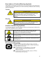
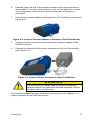
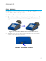
DUSTTRAK™ II AEROSOL MONITOR MODEL 8530/8531/8532/8530EP OPERATION AND SERVICE MANUAL P/N 6001893, REVISION M DECEMBER 2014 DustTrak II 8530/31 Desktop and 8532 Handheld DustTrak II 8530EP Monitor Copyright © TSI Incorporated / 2008–2014 / All rights reserved. Address TSI Incorporated / 500 Cardigan Road / Shoreview, MN 55126 / USA Fax No. (651) 490-3824 Limitation of Warranty and Liability (effective April 2014) (For country-specific terms and conditions outside of the USA, please visit www.tsi.com.) Seller warrants the goods, excluding software sold hereunder, under normal use and service as described in the operator's manual, shall be free from defects in workmanship and material for twenty-four (24) months, or if less, the length of time specified in the operator's manual, from the date of shipment to the customer. This warranty period is inclusive of any statutory warranty. This limited warranty is subject to the following exclusions and exceptions: a. b. c. d. e. f. g. h. i. Hot-wire or hot-film sensors used with research anemometers, and certain other components when indicated in specifications, are warranted for 90 days from the date of shipment; DustTrak internal pump for Models 8530 and 8533 is warranted for two (2) years or 4000 hours, whichever comes first; DustTrak external pump for Models 8530EP and 8533EP is warranted for two (2) years or 8760 hours, whichever comes first; DustTrak internal pump for Models 8530 and 8533 is warranted for operation within ambient temperatures between 5–45°C. Warranty is void when the internal pump is operating outside of this temperature range; Parts repaired or replaced as a result of repair services are warranted to be free from defects in workmanship and material, under normal use, for 90 days from the date of shipment; Seller does not provide any warranty on finished goods manufactured by others or on any fuses, batteries or other consumable materials. Only the original manufacturer's warranty applies; This warranty does not cover calibration requirements, and seller warrants only that the instrument or product is properly calibrated at the time of its manufacture. Instruments returned for calibration are not covered by this warranty; This warranty is VOID if the instrument is opened by anyone other than a factory authorized service center with the one exception where requirements set forth in the manual allow an operator to replace consumables or perform recommended cleaning; This warranty is VOID if the product has been misused, neglected, subjected to accidental or intentional damage, or is not properly installed, maintained, or cleaned according to the requirements of the manual. Unless specifically authorized in a separate writing by Seller, Seller makes no warranty with respect to, and shall have no liability in connection with, goods which are incorporated into other products or equipment, or which are modified by any person other than Seller. The foregoing is IN LIEU OF all other warranties and is subject to the LIMITATIONS stated herein. NO OTHER EXPRESS OR IMPLIED WARRANTY OF FITNESS FOR PARTICULAR PURPOSE OR MERCHANTABILITY IS MADE. WITH RESPECT TO SELLER’S BREACH OF THE IMPLIED WARRANTY AGAINST INFRINGEMENT, SAID WARRANTY IS LIMITED TO CLAIMS OF DIRECT INFRINGEMENT AND EXCLUDES CLAIMS OF CONTRIBUTORY OR INDUCED INFRINGEMENTS. BUYER’S EXCLUSIVE REMEDY SHALL BE THE RETURN OF THE PURCHASE PRICE DISCOUNTED FOR REASONABLE WEAR AND TEAR OR AT SELLER’S OPTION REPLACEMENT OF THE GOODS WITH NON-INFRINGING GOODS. TO THE EXTENT PERMITTED BY LAW, THE EXCLUSIVE REMEDY OF THE USER OR BUYER, AND THE LIMIT OF SELLER'S LIABILITY FOR ANY AND ALL LOSSES, i INJURIES, OR DAMAGES CONCERNING THE GOODS (INCLUDING CLAIMS BASED ON CONTRACT, NEGLIGENCE, TORT, STRICT LIABILITY OR OTHERWISE) SHALL BE THE RETURN OF GOODS TO SELLER AND THE REFUND OF THE PURCHASE PRICE, OR, AT THE OPTION OF SELLER, THE REPAIR OR REPLACEMENT OF THE GOODS. IN THE CASE OF SOFTWARE, SELLER WILL REPAIR OR REPLACE DEFECTIVE SOFTWARE OR IF UNABLE TO DO SO, WILL REFUND THE PURCHASE PRICE OF THE SOFTWARE. IN NO EVENT SHALL SELLER BE LIABLE FOR LOST PROFITS, BUSINESS INTERRUPTION OR ANY SPECIAL, INDIRECT, CONSEQUENTIAL OR INCIDENTAL DAMAGES. SELLER SHALL NOT BE RESPONSIBLE FOR INSTALLATION, DISMANTLING OR REINSTALLATION COSTS OR CHARGES. No Action, regardless of form, may be brought against Seller more than 12 months after a cause of action has accrued. The goods returned under warranty to Seller's factory shall be at Buyer's risk of loss, and will be returned, if at all, at Seller's risk of loss. Buyer and all users are deemed to have accepted this LIMITATION OF WARRANTY AND LIABILITY, which contains the complete and exclusive limited warranty of Seller. This LIMITATION OF WARRANTY AND LIABILITY may not be amended, modified or its terms waived, except by writing signed by an Officer of Seller. Service Policy Knowing that inoperative or defective instruments are as detrimental to TSI as they are to our customers, our service policy is designed to give prompt attention to any problems. If any malfunction is discovered, please contact your nearest sales office or representative, or call TSI's Customer Service departmentat (800) 874-2811 (USA) or (001 651) 490-2811 (International) or visit www.tsi.com. ii CONTENTS SAFETY INFORMATION ............................................................................... V Laser Safety ................................................................................................. v Labels ......................................................................................................... vi Description of Caution/Warning Symbols ................................................... vii Caution ................................................................................................... vii Warning .................................................................................................. vii Caution and Warning Symbols ................................................................... vii Reusing and Recycling............................................................................... vii CHAPTER 1 UNPACKING AND PARTS IDENTIFICATION ......................... 1 Unpacking the DustTrak II Aerosol Monitor .................................................. 2 Optional Accessories ................................................................................ 7 Parts Identification for the DustTrak II Desktop Aerosol Monitor Models 8530/8531 .................................................................................... 8 Parts Identification for the DustTrak II Desktop Aerosol Monitor Model 8530EP .......................................................................................... 9 External Pump Module (8530EP only) ......................................................... 9 Parts Identification for the DustTrak II Handheld Aerosol Monitor Model 8532 ............................................................................................. 10 CHAPTER 2 SETTING UP .......................................................................... 11 Supplying Power to the DustTrak II Aerosol Monitor .................................. 11 Installing the Batteries in Model 8530/8531/8530EP Desktop ................ 11 Installing the Batteries in Model 8532 Handheld ..................................... 11 Connecting the External Pump to DustTrak Model 8530EP ................... 12 Using the AC Adapter to Run Instrument................................................ 14 Battery Charging ..................................................................................... 14 Inlet Cap ................................................................................................. 14 Size-Selective Impactors ........................................................................ 15 Dorr-Oliver Cyclone ................................................................................ 16 Instrument Setup ........................................................................................ 16 Connecting to the Computer ................................................................... 16 Installing TrakProTM Data Analysis Software .......................................... 16 Connecting Analog/Alarm Output ........................................................... 17 Wiring the Analog Output ........................................................................... 18 Wiring the Alarm......................................................................................... 18 CHAPTER 3 OPERATION .......................................................................... 19 Getting Started ........................................................................................... 19 For Model DustTrak 8530EP only .............................................................. 19 Setup Menu ................................................................................................ 22 Zero Cal .................................................................................................. 23 Flow Cal.................................................................................................. 24 User Cal.................................................................................................. 25 Alarm ...................................................................................................... 30 Analog .................................................................................................... 32 Settings .................................................................................................. 33 Run Mode ............................................................................................... 35 Survey Mode .......................................................................................... 36 iii Manual Mode.......................................................................................... 37 Log Mode (1–5) ...................................................................................... 38 Taking Mass Concentration Measurements ............................................... 39 Screen Regions ...................................................................................... 40 Stats ....................................................................................................... 41 Graphing ................................................................................................ 41 Viewing Data .............................................................................................. 43 Title Bar ..................................................................................................... 44 CHAPTER 4 MAINTENANCE ..................................................................... 45 Maintenance Schedule .............................................................................. 45 Zeroing Instrument ..................................................................................... 46 Cleaning the Inlet ....................................................................................... 46 Cleaning and Oiling Impactors ................................................................... 47 Replacing the Internal Filters ..................................................................... 48 Replacing the Filters in the External Pump Module ................................... 51 Storage Precautions .................................................................................. 52 CHAPTER 5 TROUBLESHOOTING ........................................................... 53 APPENDIX A SPECIFICATIONS ............................................................... 59 APPENDIX B ZERO MODULE .................................................................. 61 INDEX ........................................................................................................... 63 These Application Notes can also be found on TSI’s web site: http://www.tsi.com EXPMN-001 DustTrak II Theory of Operation.pdf EXPMN-003 DustTrak II Impactor.pdf iv Safety Information IMPORTANT There are no user serviceable parts inside the instrument. Refer all repair and maintenance to a qualified factory-authorized technician. All maintenance and repair information in this manual is included for use by a qualified factory-authorized technician. Laser Safety The Model 8530/8531/8532 DustTrak II monitor is a Class I laser-based instrument. During normal operation, you will not be exposed to laser radiation. Precaution should be taken to avoid exposure to hazardous radiation in the form of intense, focused, visible light. Exposure to this light may cause blindness. Take these precautions: DO NOT remove any parts from the DustTrak II monitor unless you are specifically told to do so in this manual DO NOT remove the housing or covers. There are no serviceable components inside the housing. WARNING The use of controls, adjustments, or procedures other than those specified in this manual may result in exposure to hazardous optical radiation. WARNING There are no user-serviceable parts inside this instrument. The instrument should only be opened by TSI or a TSI approved service technician. W A R N I N G If the DustTrak monitor is used in a manner not specified by the manufacturer, the protection provided by the equipment may be impaired. When operated according to the manufacturer’s instruction, this device is a Class I laser product as defined by U.S. Department of Health and Human Services standards under the Radiation Control for Health and Safety Act of 1968. A certification and identification label like the one shown below is affixed to each instrument. v Labels Advisory labels and identification labels are attached to the instrument. 1. Serial Number Label (bottom) 2. Laser Radiation Label (internal) DANGER! VISIBLE LASER RADIATION WHEN OPEN. AVOID DIRECT EXPOSURE TO BEAM WARNING: NO USER SERVICABLE PARTS INSIDE. REFER SERVICING TO QUALIFIED PERSONNEL 3. Battery label or 4. European symbol for non-disposable item. Item must be recycled. vi Description of Caution/Warning Symbols Appropriate caution/warning statements are used throughout the manual and on the instrument that require you to take cautionary measures when working with the instrument. Caution Caution Failure to follow the procedures prescribed in this manual might result in irreparable equipment damage. Important information about the operation and maintenance of this instrument is included in this manual. Warning WARNING Warning means that unsafe use of the instrument could result in serious injury to you or cause damage to the instrument. Follow the procedures prescribed. Caution and Warning Symbols The following symbols may accompany cautions and warnings to indicate the nature and consequences of hazards: Warns that the instrument contains a laser and that important information about its safe operation and maintenance is included in the manual. Warns that the instrument is susceptible to electro-static discharge (ESD) and ESD protection should be followed to avoid damage. Indicates the connector is connected to earth ground and cabinet ground. Reusing and Recycling As part of TSI Incorporated’s effort to have a minimal negative impact on the communities in which its products are manufactured and used: Do not dispose of used batteries in the trash. Follow local environmental requirements for battery recycling. If instrument becomes obsolete, return to TSI for disassembly and recycling. vii (This page intentionally left blank) viii Chapter 1 Unpacking and Parts Identification Carefully unpack the Model 8530/8531/8532 DustTrak™ II Aerosol Monitor from the shipping container. Use the tables and illustrations below to make certain that there are no missing components. Contact TSI immediately if anything is missing or damaged. Note If you purchased a DustTrak II Model 8530-NA (no accessories) Aerosol Monitor, it only comes with the following items: DustTrak II Model 8530 Aerosol Monitor Operations manual TrakPro™ Data Analysis Software CD One-year calibration certificate Service paperwork 2-year warranty All accessories for the DustTrak II Model 8530 Aerosol Monitor are sold separately. Contact TSI at (800) 874-2811 for information on accessories and how to purchase them through a TSI sales representative. (continued on next page) 1 Unpacking the DustTrak II Aerosol Monitor Compare all the components you received with those listed in the table below. If any parts are missing, contact TSI. Item Part Number Description 8530 8531 Desktop II Desktop II HC 8532 Handheld II 801670 Desktop II Carrying Case 801669 Handheld II Carrying Case 1 1090014 Data Analysis Software CDROM 1 800663 Zero Filter Qty 1 or 1 2 Chapter 1 Item Qty Part Number 1 801680 or Description 6600 mAH Lithium Ion Rechargeable Battery (Desktop) 801681 Rechargeable lithium ion battery (Handheld) Unpacking and Parts Identification 1 1303740 USB cable 1 801652 Analog/alarm output cable (Desktop models only) 1 6001893 Operation and Service Manual 1 N/A Calibration Certificate 3 Item Qty Part Number 1 801688 Conductive Tubing 1 801668 Filter removal tool (Spanner Driver) 4 801673 Spare Internal Filter Elements Desktop Model Only 2 Description 37-mm filter includes: Filter body top Filter body bottom Mesh screen 1 Comes with 37-mm cartridge opening tool 8 801666 Spare Internal Filters Handheld Model Only 4 Chapter 1 Item Qty Part Number Description 1 801667 Impactor Kit PM2.5 assembled Top Bottom Impaction Plate PM1.0 Top PM4.0 Top PM10 Top Extra Impaction Plate 1 801691 Dorr-Oliver Cyclone 1 801692 Power Supply – Desktop 801694 Power Supply – Handheld N/A Stylus 2 When shipped, one stylus will be in the accessory bag, the second stylus attached to instrument. 1 Unpacking and Parts Identification 3012094 Screwdriver, dual ended. (For Handheld Models only) 5 Item Qty Part Number Description 1 801674 Impactor Oil 2 801698 Inlet cap When shipped, one inlet will be in the accessory bag, the second inlet attached to instrument. 1 801675 External Pump Kit for 8530EP only 1 801797 External Pump Power Cable (to DustTrak monitor) for 8530EP only 1 1 6 801798 External Pump Flow Tube (to DustTrak monitor) for 8530EP only Exhaust Adapter, DustTrak monitor for 8530EP only Chapter 1 Optional Accessories The following photos and table list optional accessories. If you ordered optional accessories, make certain they have been received and are in working order. Accessories Unpacking and Parts Identification Qty Part Number 1 801675 External Pump Kit 2 801795 DustTrak II/DRX External Pump Service Kit for 8530EP only. Contains two filters for External Pump 1 801685 Battery Charger, 2-Bay, Battery 801680 for Desktop DustTrak monitor 1 801686 Battery Charger, Battery 801681 for Handheld DustTrak monitor Description 7 Parts Identification for the DustTrak II Desktop Aerosol Monitor Models 8530/8531 Stylus Inlet On/Off Touchscreen Power Analog/Alarm Output USB Host USB Device Ethernet Zero Module Connector Filter Access Battery Access Figure 1-1: Features on Desktop Model 8530/8531 8 Chapter 1 Parts Identification for the DustTrak II Desktop Aerosol Monitor Model 8530EP External Pump Power Connection External Pump Flow Tubing Exhaust Adapter External Pump External Pump Module (8530EP only) Pump Pump Suction End User Replaceable HEPA Filters Pump Exhaust End Pump Power Connection Figure 1-2: Features on Desktop Model 8530EP Unpacking and Parts Identification 9 Parts Identification for the DustTrak II Handheld Aerosol Monitor Model 8532 Inlet On/Off Touchscreen Stylus Port Cover Power USB Host USB Device Filter Access Battery Access (Screw Lockdown) Figure 1-3: Features on Handheld Model 10 Chapter 1 Chapter 2 Setting Up Supplying Power to the DustTrak II Aerosol Monitor The DustTrak II Aerosol Monitor must be powered by either batteries or using the external AC adapter. WARNING The instrument has been design to be used with batteries supplied by TSI. Do not use a substitute. Disposing of old batteries must be recycled in accordance with the local environmental regulations. WARNING Do not use non-rechargeable batteries in this instrument. Fire, explosions, or other hazards may result. Installing the Batteries in Model 8530/8531/8530EP Desktop Remove the battery cover and slide one or two batteries into the battery slots. A single battery can be put into either slot. Orient the batteries with the label side facing up (see Figure 2-1). Figure 2-1: Batteries into Desktop Unit Installing the Batteries in Model 8532 Handheld Remove the battery cover by loosening captured screw on the bottom of the unit. Orient battery with brass connectors facing forward. Insert battery into cavity and slide forward to engage into pins. Replace the battery cover and secure by tightening screw (see Figure 2-2). 11 Figure 2-2: Batteries into Handheld Unit Connecting the External Pump to DustTrak Model 8530EP The Model 8530EP is a Desktop DustTrak monitor with an external pump. This DustTrak has no internal pump and will not work with any other external pump other than the one provided by TSI (p/n 801675). The Model 8530EP is intended for applications where the DustTrak is operated continuously over extended periods (several days to months) under wide temperature fluctuations (0 to 50°C). The external pump is designed to be more robust for 24/7 operation of the DustTrak monitor and is warranted to operate continuously for one full year or 8760 hours. The Model 8530EP is ideal for fugitive dust monitoring. The pump and the DustTrak monitor come separately and require assembly. Follow the steps below to connect the pump with the Model 8530EP DustTrak monitor. WARNING Turn the DustTrak monitor OFF before connecting the external pump. Turn the DustTrak monitor ON only after connecting the External Module. 1. Connect the pump end of the quick connect to the pump module (see Figure 2-3). Figure 2-3: Connect Pump End of Quick Connect to Pump Module 12 Chapter 2 2. Likewise, plug one end of the power connector to the pump module as shown above. Turn the power connector until it clicks and locks in place. This prevents the connector from disconnecting due to vibration or movement. 3. Connect the exhaust adapter to the exhaust of the DustTrak monitor (see Figure 2-4). Figure 2-4: Connect Exhaust Adapter to Exhaust of DustTrak Monitor 4. Connect the other end of the flow tubing to the exhaust adapter of the DustTrak monitor. 5. Connect the other end of the power connector to the DustTrak monitor (see Figure 2-5). Figure 2-5: Connect Power Connector to DustTrak Monitor WARNING The Pump module design does not allow for installation outdoors without any protection from the elements. Always operate it within an enclosure. The DustTrak external pump module does not require an A/C adapter. It is always powered off the DustTrak monitor. Setting Up 13 Notes 1. The power connector and the flow quick connect “click” when securely connected. The power connector must be rotated clockwise past the locking pin. 2. Do not hot-plug the External Pump Module when the DustTrak monitor is turned ON. Always connect the External Pump module first and then turn the DustTrak monitor ON. 3. TSI recommends that the DustTrak monitor with the external pump be operated in the Model 8535 Environmental Enclosure. 4. TSI recommends that the pump module be operated when mounted on its feet and avoid operating at other orientations as much as possible. 5. Pump module and the DustTrak monitor should be at the same electrical potential. 6. The additional port on the external pump module is where the pump exhausts the flow. For applications where the DustTrak monitor is sampling from a chamber or a duct at pressures significantly different from the ambient, TSI recommends plumbing the exhaust of the external pump back in to the chamber/duct. Using the AC Adapter to Run Instrument The AC adapter allows you to power the DustTrak monitor from an AC wall outlet. When using the AC adapter, the batteries (if installed) are bypassed. Battery Charging This instrument will charge the Lithium Ion battery packs. Insert the batteries into the battery compartment, plug the instrument into AC power, and turn the instrument on. Batteries will charge only when the instrument is on and in stand-by mode. Batteries will not charge if the instrument is turned off or is actively taken measurements. Charging will stop when the batteries are fully charged. WARNING When Charging Battery the ambient temp must not exceed 42°C. Inlet Cap When using the DustTrak monitor to sample environmental air, the inlet cap should be put over the instrument. This cap will keep large objects from dropping into and plugging the inlet. The cap will also keep direct light from shinning into the chamber and skewing the results. The inlet cap can simply be pressed onto the instruments inlet. 14 Chapter 2 Figure 2-6: Putting on Inlet Cap Size-Selective Impactors Size-selective impactors can be attached to the inlet of the DustTrak II instruments. Size-selective impactors can be used to pre-condition the size range of the particles entering the instrument. PM1, PM2.5, PM4 (Respirable) and PM10 impactors are available. The instrument must run at the factory default setting of 3.0 L/min for the impactors to achieve the correct cut points. The size-selective impactor is composed of three parts; the cap, impaction plate and bottom. Selection of the cap will determine cut size of the impactor. Each cap is labeled with the particle cut size (1 µm, 2.5 µm, 4.0 µm or 10 µm). The same impaction plate and bottom are used on all impactor sizes. Cap (1 µm, 2.5 µm, 4 µm or 10 µm) Impaction Plate Bottom Figure 2-7: Size-Selective Impactor The impactor assembly is attached to the instrument in place of the inlet cap. The inlet cap does not need to be used if an impactor is being used. See Chapter 4, "Maintenance," for instructions on how to add oil to the impaction plate. Setting Up 15 Dorr-Oliver Cyclone A Dorr-Oliver cyclone is shipped with the instrument. The Dorr-Oliver cyclone removes particles over 4.0 µm in size. The Dorr-Oliver cyclone is attached to the instrument by sliding the cyclone clip over the protruding catch. The tube from the Dorr-Oliver cyclone needs to be routed to the inlet of the instrument. Figure 2-8: Installing Door-Oliver Cyclone Do not use Inlet attachments (impactors or inlet cap) when using the DorrOliver Cyclone. The instrument flow rate must be changed to 1.7 L/min when using the Dorr-Oliver Cyclone in order to achieve a 4 µm (respirable) cut-point. See the Flow Cal instructions in the Operations chapter for instructions on how to change the instruments flow rate. Instrument Setup The DustTrak II monitor can be connected to a computer to download data and upload sampling programs. Connecting to the Computer Connect the USB host port of a Microsoft Windows®-based computer to the USB device port on the side of the DustTrak monitor. Installing TrakProTM Data Analysis Software TrakPro software can preprogram the DustTrak monitor, download data, view and create raw data and statistical reports, create graphs, and combine graphs with data from other TSI instruments that use TrakPro software. The following sections describe how to install the software and set up the computer. Note To use TrakPro software with the DustTrak Aerosol Monitor, the PC must be running Microsoft Windows® and the computer must have an available Universal Serial Bus (USB) port. ® Windows is a registered trademark of Microsoft Corporation. 16 Chapter 2 1. Insert the TrakPro Data Analysis Software CD into the CD-ROM drive. The install screen starts automatically. Note If the software does not start automatically after a few minutes, manually run the program listed on the label of the CD using the Run command on the Windows Start Menu. 2. Follow the directions to install TrakPro software. TrakPro software contains a comprehensive installation guide. TSI recommends printing out this guide prior to starting the TrakPro software installation on your computer, so it may be consulted during the installation. The TrakPro Software manual is located in the “Help” file in TrakPro software. There is no separately printed TrakPro Data Analysis software manual. Connecting Analog/Alarm Output The Analog/Alarm Output Cable plugs into the alarm connection on the side of the instrument. This feature is on the desktop models (8530/8531) only. The cable contains a 4-pin, mini-DIN connector. The pin-outs for the connector and the wiring for the cable are shown below. Alarm Positive (+) Analog Output (+) Analog Ground (–) Alarm Ground (–) 4-pin miniDIN connector Cable Wiring Diagram Brown Wire Analog Ground Orange Wire Analog Out Red Wire Alarm (+) White Wire Alarm (-) Black Wire Shield Figure 2-9: Cable Wiring Diagram ® Microsoft and Windows are registered trademarks of Microsoft Corporation. Setting Up 17 Wiring the Analog Output System specifications: Output voltage: 0 to 5 VDC. With a maximum output of 15 mA. Output Current 4 mA to 20 mA with a maximum load impendence of 250 ohms. Correct polarity must be observed (see pin-outs above). The output cable supplied by TSI (part no. 801652) is labeled with the pin-out wiring diagram. Additional equipment may be needed for making connections to the system that TSI does not supply. It is your responsibility to specify and supply all additional equipment. Wiring the Alarm System specifications: Maximum voltage: 15 VDC (DO NOT USE AC POWER) Maximum current: 1 Amp Correct polarity must be observed (see pin-outs above) The alarm switch, located inside the DustTrak monitor must be located on the ground side of the alarm system. WARNING The DustTrak monitor Alarm Output function should not be used to detect hazardous conditions or to provide an alarm for protecting human life, health or safety. Caution The alarm switch must not be wired to AC power! Failure to install the user alarm properly could damage the DustTrak instrument and/or void the instrument warranty! Please read and follow all instructions before wiring or operating the user alarm. W A R N I N G When connected to the analog out and alarm out connector, you must use safety certified equipment and/or power sources. 18 Chapter 2 Chapter 3 Operation Getting Started The START UP screen is displayed initially when the instrument is turned on, following the initial TSI logo splash screen. Use a stylus or fingertip, touch the “buttons” on the screen to activate different menus. For Model DustTrak 8530EP only W A R N I N G Always setup and operate the DustTrak monitor with External Pump Module with the External Pump Module connected to the DustTrak monitor. Failure to do so will result in communication errors. 19 Communication errors take place under four different scenarios as follows: 1. When the unit is idle and is not connected to the External Pump Module, a warning displays on the Main screen. Note “No Pump is Connected” is a sticky error. Even after the warning message, if the External Pump Module is connected to the DustTrak, the error will not disappear until the screen is refreshed. Refresh the screen by going into a different menu and returning to the Main menu. 2. 20 When the unit is not connected to the External Pump Module and an attempt is made to start a run by selecting “Start”, an error appears on the Main screen. Chapter 3 3. If the pump is not connected while attempting to perform a Zero Cal, an error appears on the Setup screen. 4. If the pump is not connected while attempting to perform a Flow Cal, an error appears on the Setup screen. Operation 21 Setup Menu Pressing Setup activates the Setup Menu touchscreen buttons along the left edge of the screen. Setup is not accessible when the instrument is sampling. The main screen of the Setup screen displays the following information: Serial Number The instruments serial number. Model Number The instruments model number. Firmware Version Instruments current version of firmware. Calibration Date Date of the last factory calibration. Pump Run Time Pump running time in hours. Cum Mass Conc Amount of mass run through instrument over life. Cum Filter Conc Amount of mass run through instrument since last filter change. Filter Time Date of last filter change. 22 Chapter 3 Zero Cal Run Zero Cal the first time the instrument is used and repeat prior to every use. Zero Cal requires that the zero filter be attached prior to running. Zero Cal must also be performed if the unit is reading negative concentrations. It is not possible for the DustTrak to read negative concentrations. Negative concentrations are a symptom of zero drift. Never perform a zero cal without attaching a zero filter. 1. Press Zero Cal Button 2. Attach Zero Filter 3. Press the Start button to start Zeroing process. 4. A count-down clock will appear indicating the time remaining. The screen with indicate “Zero Cal Complete” when done. Remove filter after zeroing has been completed. The instrument is now zero calibrated and ready for use. Operation 23 Flow Cal Run Flow Cal to change the flow set point. The flow set point is factory set to 3 L/min total flow. 2 L/min of the total flow is measured aerosol flow. 1 L/min of total flow is split off, filtered, and used for sheath flow. There is an internal P flowmeter in the DustTrak II instrument that controls flow rate to ±5% if factory setpoint. TSI recommends checking the flows with an external flow reference meter, especially when collecting data. The pump will automatically start when entering the Flow Cal screen. 1. Attach a flow calibrator (reference flow meter) to inlet port. You may use a bubble buret, mass flow meter, dry piston or rotameter as flow measurement devices. 2. Move the arrows up or down to achieve desired flow on the reference flowmeter. Each up or down arrow will change the flow about 1%. Allow time between button presses to let pump change to the new flow rate. Select Save once the desired flow rate is achieved. Select Undo to return to the factory set point. Note The flow rate can be adjusted from approximately 1.5 to 4.0 L/min. For Model 8533/8534, the FlowCal feature allows you to re-adjust the flow rate to 3.0 L/min. While the flow rate for Model 8533/8534 is fixed at 3.0 L/min, the flow rate for Model 8530/8532 can be changed. This allows for the use of other size selective inlets like cyclones or impactors with Model 8530/8532. No size-selective inlets should be installed on the inlet of Model 8533/8534 during its normal operation. 24 Chapter 3 User Cal User Cal allows you to store and use 10 different calibration factors. In addition, there are two factory defaults, one is the “Ambient Cal” and the other is the “Factory Cal”. The “Ambient Cal” is appropriate for outdoor ambient dust or fugitive dust monitoring. The “Factory Cal” is the calibration to ISO 12103-1, A1 Arizona test dust for which a calibration certificate is provided with the instrument. The “Factory Cal” is appropriate for most workplace aerosol monitoring. The currently active user calibration is highlighted with an asterisk “*”. Four variables can be set for each user calibration. Operation 25 Name User can rename calibration to a description name. Photometric Changes the factory calibration of particle signal, based on Arizona Road Dust, to actual aerosol being measured. See below for sets to set this calibration. Size Corr Changes the factory calibration of the particle distribution, based on Arizona Road Dust, to actual aerosol being measured. See below for sets to set this calibration. User Cal [on,off] Selecting On will activate current user calibration and deactivate the previously selected user calibration. Taking a Gravimetric Sample Using the DustTrak Monitor When sampling with the DustTrak monitor, you can simultaneously take a gravimetric sample either for custom calibration of the DustTrak monitor or for collecting the sample on to the gravimetric filter downstream of the DustTrak monitor without a need for additional gravimetric sampling pump and filter assembly. To accomplish this, follow the instructions given below: 1. Setup the DustTrak monitor to sample how long you want the sample run time to be. The following example shows a sample for 8 hours. 2. Under RunMode menu, put the instrument in Manual Log (Manual Logging is reviewed later in this section), which will enable you to start and stop the pump at any time you choose. 3. Set the logging interval. One minute (i.e., “01:00”) is a good choice. 4. Make sure you have a preweighed 37-mm gravimetric filter cassette loaded into the DustTrak monitor. See Chapter 4, “Replacing the Internal Filters” on how to access the filter (see figure 4-8) and replace it. Note Use only the conductive plastic filter cassette holder (SKC Part# 225-308). 5. 26 Under the Setup Menu, make sure the DustTrak monitor is set to the desired flow rate. For DustTrak II Models 8530 and 8531, the flows can be varied from 1.7 to 4 L/min for use with various inlet conditioners. For DustTrak DRX Model 8533, the flow cannot be changed. The flows for DustTrak II monitor can be changed by changing the default flow calibration setpoint from 1.0 to any value between 0.5 to 1.5 in the span adjustment. An external flowmeter is needed to measure the total flow. Flow can be changed by clicking on the UP or DOWN arrow keys shown below: Chapter 3 6. 7. Conduct a preflow calibration on the DustTrak monitor using the same kind of sample media you will sample with. Now, attach the sample media you intend to sample with and start sampling aerosol for the desired time. After the desired run time, stop the sampling. Remove the filter from the DustTrak monitor and follow your laboratory’s criteria for filter post weight. Conduct a post-flow calibration with the same sample media done with the pre-flow calibration and determine if these flow calibrations are within ±5% of each other. If they are, use the following to calculate the actual flow rate for the DustTrak monitor. The laboratory will need the following information to calculate mass concentration in mg/m3: Total sample time in minutes. Flow rate—flow rate of the DustTrak monitor used for gravimetric analysis is only 2/3 the total flow since 1/3 of the flow is used as sheath flow. Total liters of air sampled = total sample time x flow rate. Using this information the laboratory can determine the concentration using the following formula: 𝑚𝑔 𝐶𝑜𝑛𝑐𝑒𝑛𝑡𝑟𝑎𝑡𝑖𝑜𝑛, 3 = 𝑚 𝐹𝑖𝑙𝑡𝑒𝑟 𝑃𝑜𝑠𝑡 𝑊𝑒𝑖𝑔ℎ𝑡 𝑚𝑔 − 𝐹𝑖𝑙𝑡𝑒𝑟 𝑃𝑟𝑒 𝑊𝑒𝑖𝑔ℎ𝑡 𝑚𝑔 × 𝑇𝑜𝑡𝑎𝑙 𝑆𝑎𝑚𝑝𝑙𝑒 𝑇𝑖𝑚𝑒 (𝑚𝑖𝑛) 𝐷𝑢𝑠𝑡𝑇𝑟𝑎𝑘™ 𝑀𝑜𝑛𝑖𝑡𝑜𝑟 𝐹𝑙𝑜𝑤 𝑅𝑎𝑡𝑒 (𝐿/𝑚𝑖𝑛) 2 × 3 1000 Note The flow rate used for gravimetric analysis is only 2/3 the total flow since 1/3 of the flow is used as sheath flow. 8. For instructions on how to calibrate the DustTrak monitor using this data, see section below on “Determining the Calibration Factor for a Specific Aerosol”. Operation 27 Photometric Calibration Factor In most situations, the DustTrak monitor with its built-in data logging capability can provide very good information on how the concentration of an aerosol changes for different processes over time. Factory calibration to the respirable fraction of standard ISO 12103-1, A1 test dust is fairly representative of a wide variety of workplace aerosols. Because optical mass measurements are dependent upon particle size and material properties, there may be times in which a custom calibration would improve your accuracy for a specific aerosol. Determining a aerosol specific photometric calibration requires that you determine a true mass concentration (e.g., gravimetric analysis) for the aerosol you want to measure. The true mass concentration is used to calculate the custom calibration factor for that aerosol. Once you have a custom calibration factor, you can reuse it each time you make measurements in the same aerosol environment. Determining the Calibration Factor for a Specific Aerosol The DustTrak II monitor is factory calibrated to the respirable fraction of standard ISO 12103-1, A1 test dust. The DustTrak monitor can be easily calibrated to any arbitrary aerosol by adjusting the custom calibration factor. The DustTrak monitor’s custom calibration factor is assigned the value of 1.00 for the factory calibration to standard ISO test dust. This procedure describes how to determine the calibration factor for a specific aerosol. Using the value of 1.00 will always revert back to the factory calibration. To determine a new calibration factor you need some way of accurately measuring the concentration of aerosol, hereafter referred to as the reference instrument. A gravimetric analysis is often the best choice, though it is limited to nonvolatile aerosols. The internal 37 mm filter cartridge, in the desktop units, can be used to collect the reference gravimetric reference sample. To make an accurate calibration you must simultaneously measure the aerosol concentration with the DustTrak monitor and your reference instrument. 1. Zero the DustTrak II monitor. 2. Put the instrument in Manual Log (Manual Logging is reviewed later in this section). 3. Set the logging interval. One minute (i.e., “01:00”) is often a good choice. 4. Co-locate the DustTrak II monitor and the reference sampler together so that they are measuring from the same area. The 37-mm filter cartridge in the desktop unit can be used to collect the particles to be weighed for the gravimetric reference. 5. Start sampling aerosol with both instruments at the same time. 28 Chapter 3 Note Greater accuracy will be obtained with longer samples. The time you permit for sampling often depends on the reference instrument and characteristics of the measured aerosol. It may take some time to collect sufficient aerosol onto a filter cassette for accurate gravimetric analysis. Refer to instructions of your reference instrument for sampling times. 6. Stop sampling with both instruments at the same time. 7. Record the DustTrak monitor average concentration by viewing the sample average in the Data screen. (Data Screen is reviewed later in this chapter.) 8. Determine the mass concentration in mg/m3 from your reference instrument. For gravimetric sampling this means weighing the gravimetric sample. Note If you used the internal gravimetric filter in the DustTrak Model 8530 or 8531, the flow rate used to compute the concentration should be 2 L/min, not 3 L/min since only 2 L/min of aerosol flow reaches the filter. 9. Compute the new calibration constant, NewCal, using the following formula: Reference Concentration NewCal CurrentCal DustTrak Concentration 10. Select Photometric from the User Cal drop down selection and enter the NewCal factor using the onscreen controls. Operation 29 Alarm Alarm allows you to set an alarm level that will be triggered if the instrument’s reading goes above the setpoint. However, the alarm functioning is determined by the logging interval. The alarm will turn ON only if the average concentration over the logging interval exceeds the set point. If the logging interval is too long and the concentration exceeds the set point and stays at that level, the alarm will not turn ON until after the logging interval has passed. Likewise, the alarm will not stop until after the concentration has dropped below 5% of the threshold and after the logging interval has passed. Note The Alarm is dependent on the logging interval. For the DustTrak to alarm as soon as the Alarm Setpoint is exceeded, the logging interval must be set as low as possible (i.e., 1 second or 2 seconds). If a long test duration does not permit setting such a short logging interval, use the STEL alarm instead. The STEL is always based on 1 second concentrations and is independent of the logging interval. For more details on the STEL alarm, see section below on STEL. In Survey mode, the alarm is dependent on the time constant. Alarm1 Setpoint [mg/m3] The alarm1 setpoint is the mass concentration level upon which the alarm1 is triggered. Alarm will trigger if the mass concentration, taken at the logging interval, rises above the setpoint. Note: Alarm 2 must be lower than Alarm 1 when both alarms are enabled. 30 Chapter 3 When the relay alarm is turned on, unit will close relay switch when Alarm1 level is surpassed. Alarm1 Relay [On, Off] Relay selection is available on the 8530 and 8531 desktop models only. When the STEL alarm is turned on, STEL data will be collected when Alarm1 level is surpassed. Alarm1 STEL [On, Off] STEL selection is available on the 8530 and 8531 desktop models only. See STEL Note below. 3 Alarm2 Setpoint [mg/m ] The alarm2 setpoint is the mass concentration level upon which the alarm2 triggers. Alarm triggers if the mass concentration, taken at the logging interval, rises above the setpoint. Note: Alarm 2 must be lower than Alarm 1 when both alarms are enabled. Alarm2 Enable [On, Off] Enables Alarm2 to be logged and will activate the Audible or Visible alarms if they are enabled. Alarm Audible [On, Off] When the audible alarm is turned on, the instrument will activate internal beeper when Alarm1 or Alarm2 level is surpassed. Alarm1 Visible [On, Off] When the visible alarm is turned on, unit will show the alarm icon (Alarm1 , Alarm 2 ) in title bar when Alarm1 or Alarm2 level is surpassed. Operation 31 STEL Alarm STEL stands for Short Term Exposure Limit. When a STEL alarm is selected, the instrument will inspect the data on a second by second basis, independent from the selected logging interval. If the mass exceeds the STEL limit, then a STEL even triggers and the following actions will be taken. STEL indicator The STEL indicator will show Red on the main screen. Data Data will be taken of the STEL alarm channel at a 1 minute logging interval for 15 minutes. This data will be stored in a separate file named STEL_XXX, where XXX will be matched to the logged data file. The instrument will also continue to log the mass concentration data at the logging interval selected. STEL Alarm repeat If the instrument remains over the STEL limit after the 15 minute interval, or if the instrument exceeds the STEL limit later during the sample period, additional STEL files will be generated. Analog 32 Chapter 3 Analog setup screen sets the parameters that will drive the analog out port. Applies to the 8530/8531 Desktop models only. Analog out [On, Off] Turns analog out port on. Size Fraction Selects the size channel that will drive the analog out. Output Setting [V, mA] 3 Select between 0 to 5 V and 4 to 20 mA. Lower Limit [mg/m ] Mass concentration reading of the selected channel that will correspond to 0 V or 4 mA. Upper Limit [mg/m3] Mass concentration reading of the selected channel that will correspond to 5 V or 20 mA. Settings Settings screen sets basic unit parameters. Date Time Sets current date, current time and date/time format. Time can be set in 12 or 24 hour format. Date can be set in yyyy/dd/mm, yyyy/mm/dd or yyyy/dd/mm. Operation 33 Background Switches between blue and white backgrounds. Touch Cal Calibrates the touch cal screen. IP USB PORT IP Address: USB IP is the address assigned to the instrument by the NDIS driver. It is shown but cannot be changed. Ethernet Port IP parameters: (Model 8530, 8531 Desktop only.) IP method can be set to static or dynamic. For static IP, IP address, default gateway, and subnet mask can be set. For Dynamic, The IP assigned by the network is shown. This cannot be changed. See Note below. IP Note After changing the instrument to Dynamic or Static, reboot the instrument. In Dynamic Mode, the unit will show the IP to which is assigned (after being rebooted). 34 Chapter 3 Language Switches between display languages. After changing the display language, reboot the instrument. Run Mode Operation 35 The RunMode tab brings up sampling mode options. Sampling mode options include Survey Mode, Manual Log, and Log Mode 1-5. Survey Survey Mode runs a real time, continuous active sample, but does not log data. Manual Manual Log sets the instrument to log data for a specified run time. Log Modes Log Mode starts and stops the instrument at specified times, run for a specified test length, and perform multiple tests of the same length with a specified time period between tests. Survey Mode Time Constant Time Constant can be set from 1 to 60 seconds. This will control the update rate of the main screen. It is the rolling average of data displayed on the main screen and is not linked to logged data in either Manual or Program Log modes. Auto Start on Power Up When set to “Yes”, unit will start a measurement upon being powered on, if the unit was set to “Survey” when it was turned off. When set to “No”, the unit will be in idle when it is powered on. 36 Chapter 3 Manual Mode Log Interval The log interval can be set from 1 second to 60 minutes. It is the amount of time between logged data points. Test Length Test length can be set from 1 minute to the limit of the data storage. Time Constant Time Constant can be set from 1 to 60 seconds. This will control the update rate of the main screen. It is the rolling average of data displayed on the main screen and is not linked to logged data in either Manual or Program Log modes. In Manual mode, data will be stored to a file named “Manual_XYZ” where XYZ is an incrementing integer. Operation 37 Log Mode (1–5) Log Name Log Name, brings up a virtual keypad to name the Logged Data file. Start Date Start Date, select the date the test will start. Start Time Start Time, select the time the test will start. Log Interval The log interval can be set from 1 second to 60 minutes. It is the amount of time between logged data points. Auto Zero Interval Interval between re-zeroing the instrument using the Auto-Zero accessory. Models 8530 and 8531 desktop only. Test Length From 1 minute to the limit of the data storage. Number of Tests Number of tests, 1 to 999. Time between Tests Time between tests, 1 minute to 30 days. Time Constant Time Constant can be set from 1 to 60 seconds. This will control the update rate of the main screen. It is the rolling average of data displayed on the main screen and is not linked to logged data in either Manual or Program Log modes. Use Start Date Use Start Date, option to use programmed start date or by pass programmed start date. Use Start Time Use Start Time, option to use programmed start time or bypass programmed start time. In Log mode, data will be stored to a file named “LogName_XYZ” where LogName is the user entered log name and XYZ is an incrementing integer. 38 Chapter 3 Taking Mass Concentration Measurements Measurements are started and controlled from the main screen. Prior to starting a measurement the instrument should be zeroed from the Setup screen and the run mode should be configured and selected from the RunMode screen. When the instrument is on, but not taking any mass measurements the start button will be green and instruments pump will not be running. To start taking a measurement, press the green start button. For the Model 8530EP DustTrak monitor with external pump, make sure the external pump is connected to the DustTrak monitor as described in Chapter 2. If the pump is not connected and the green start button is pressed, the DustTrak monitor will identify that the pump is not connected and a warning will be displayed as shown below: Operation 39 Connect the External Pump Module to the DustTrak monitor and then try again. TSI recommends powering down the DustTrak monitor before connecting the External Pump Module to the DustTrak monitor. Connect the power cable and the flow tubing between the DustTrak monitor and the External pump module, as applicable. While taking a measurement the screen will display the current measured mass concentration. The various regions of the screen are shown below. Screen Regions Mass Reading Run Mode File Name Test Progress Error Indicators Mass Reading Shows the instruments mass measurements. Run Mode Region Shows the run mode selected from the RunMode screen. File Name Region Displays the file name to which the data is currently being saved. Test Progress Region Shows the time-based progress of the test. Error Indicator Region Shows the current stats of the instrument STEL: Shows if STEL is in progress (desktop instruments only) Flow: Status of the flow control Laser: Status of the Laser Filter: Status of the Filter See Chapter 5, "Troubleshooting," to resolve any of these error conditions. 40 Chapter 3 Stats The Stats button shows the statistics of the mass measurement. When the Stats button is pressed, the main mass reading will reduce in font size, and the measurement statistics will show on the right side of the screen. Graphing During sampling, pressing the Graph button displays current readings in graphical form. During Survey Mode, five (5) minutes of running real-time data is displayed graphically. During Logging Mode, the entire log test time is displayed on the graph. Data Region (live area) Scale Display (live area) Operation Time Display (live area) 41 Time Display Pressing the Time x-axis label on the graph screen switches between Time (s), Time (abs), and Time (rel). Time (s): Elapsed time from first logged point (log interval) to the last logged point (test length). Time (rel): Relative time from zero to last logged point (test length – log interval). Time (abs): Absolute time from first logged point (test start + log interval) to last logged point (test stop). Scale Display Pressing in the Scale Display area will bring up a dialog that will allow changing between auto scaling and user scaling of the Y-axis. Data Region Pressing the data region will bring up a dialog to show TWA or Average lines. TWA: Will show a secondary line on the graph showing the time weighted average of the data. This line will not show if test time is less than 15 minutes. Average: Show a secondary line on the graph of the running average of the data. In Graphing Mode, pressing Main returns the instrument to the Main Screen display. 42 Chapter 3 Viewing Data The Data button opens a list of data files for viewing. Select File Press the arrows on the right side of the screen to scroll up or down to the data file to be viewed. Data Statistics Statistics on the selected file o File Name o Sample Average o Sample TWA o Sample Maximum Reading o Sample Minimum Reading o Number of Data Points in the File Save All Button Downloads data to a USB thumb drive. The USB thumb drive must be attached to the USB host port. Data is saved as a .csv file that can be viewed in Microsoft® Excel® spreadsheet software. Delete Button Deletes the currently highlighted file. Delete All Button Deletes all the files stored on the instrument. Graph Button Data can also be viewed in graphical form by pressing the Graph button while the data file is highlighted. Operation 43 Title Bar The Title Bar shows common instrument information. Current Screen Instrument Lock Battery Status Date , Time Current Screen Title of the current screen that is being displayed. Instrument Lock Icon shows if the instrument touchscreen is in an unlocked or locked condition. Unlocked: Locked: To lock the touchscreen controls, touch the “lock” icon, immediately followed by three (3) quick touches on the current screen (Main) word along the top tool bar. Repeat the process to unlock the screen. Battery Status Show the current % life of the battery and show if the battery is currently being charged: Charging: (unfilled portion of the icon is filled yellow as well as animated to indicate that the charging is in progress) Not Charging: transparent) (unfilled portion of the icon Date and Time Indicates the instruments current date and time. Alarm If the instrument is in an alarm status, an alarm icon will appear in the title bar. 44 Chapter 3 Chapter 4 Maintenance The DustTrak II aerosol monitor can be maintained in the field using the instructions below. Additionally, TSI recommends that you return your DustTrak II monitor to the factory for annual calibration. For a reasonable fee, we will quickly clean and calibrate the unit and return it to you in “as new” working condition, along with a Certificate of Calibration. This “annual checkup” helps ensure that the DustTrak II monitor is always in good operating condition. WARNING There are no user-serviceable parts inside this instrument. The instrument should only be opened by TSI or a TSI approved service technician. Maintenance Schedule The DustTrak II Aerosol Monitor requires maintenance on a regular basis. Table 4–1 lists the factory recommended maintenance schedule. Some maintenance items are required each time the DustTrak monitor is used or on an annual basis. Other items are scheduled according to how much aerosol is drawn through the instrument. For example, TSI recommends cleaning the inlet sample tube after 350 hours of sampling a 1 mg/m3 concentration of aerosol. This recommendation should be pro-rated according to how the instrument is used. 350 hours at 1 mg/m3 is the same amount of aerosol as 700 hours at 0.5 mg/m3 or 175 hours at 2 mg/m3, etc. Table 4–1. Recommended Maintenance Schedule Item Frequency Perform zero check Before each use. Clean inlet 350 hr. at 1 mg/m3* Clean 2.5 µm calibration impactor Before every use. Replace internal filters 350 hr. at 1 mg/m3* or when indicated by the main screen filter error indicator. Return to factory for cleaning and calibration (For 8530EP, TSI recommends that both the DustTrak and the External Pump Module be returned to TSI) Annually Replace the internal HEPA filters in the External Pump module Annually *Pro-rated, see discussion above. 45 The DustTrak monitor keeps track of the accumulated amount of aerosol drawn through it since its last cleaning. When the internal filter replacement is due, the filter error indicator will turn from green to red. TSI recommends you perform a zero check prior to each use for the DustTrak monitor and certainly before running any extended tests, and after the instrument experiences a significant environmental change. Examples of significant environmental changes would be ambient temperature changes that exceed 15 F (8 °C) or moving from locations with high aerosol concentrations to low concentrations. Zeroing Instrument 1. Attach the zero filter to the inlet of the instrument. Figure 4-1: Attach Zero Filter to Inlet 2. Follow zero calibration instructions detailed in the operations section of this manual. Cleaning the Inlet The inlet should be cleaned based on the schedule in Table 4–1. 1. Turn the DustTrak monitor off. 2. Unscrew the inlet nozzle from the instrument (Figure 4-2). Figure 4-2: Unscrew Inlet Nozzle 46 Chapter 4 3. Clean the inlet port. Use a cotton swab to clean the outside of the inlet port. You may dampen the swabs with water or a light solvent (e.g., isopropanol). Clean the inside of the sample tube by using a small brush, along with a light solvent. Dry the tube by blowing it out with compressed air, or let it air-dry thoroughly. Note Be careful not to blow particles into the DustTrak monitor inlet port. Figure 4-3: Do NOT Blow into Instrument 4. Screw (hand-tighten) inlet back into instrument. Cleaning and Oiling Impactors The calibration impactor should be cleaned prior to every use, using it to perform a Standard Calibration (size correction) on the instrument, as described in the Operations section. 1. Unscrew Impactor. Check O-ring on the impactor base. 2. Clean outside and inside of Impactor and the impactor plate using a clean brush and a light solvent. Dry impactor parts by blowing it out with compressed air, or let it air-dry thoroughly. 3. Apply 2 drops of oil (included) to the impactor plate. Do not over-fill impaction plate. Apply 2 Drops of Oil Figure 4-4: Apply 2 Drops of Oil to Impactor Plate Maintenance 47 4. Screw (hand-tighten) impactor back together. Replacing the Internal Filters Replace the internal filters based on the schedule in Table 4–1 or when the filter indicator on the main screen changes to red. 1. Turn the instrument off. 2. Remove old filters from the instrument. Handheld Model a. Use the enclosed filter removal tool (PN 801668) tool to unscrew the two filter caps located on the bottom of the instrument. b. Pull the old filters out of the two filter wells. If filter wells are visibly dirty, blow out with compressed air. Figure 4-5: Pull Filters Out of Two Filter Wells (Handheld Model) c. Put two (2) new filters (P/N 801666) into the filter wells and screw filter caps back into place. Note Replacement filters were shipped with the new instrument. Order additional filters from TSI under PN 801666. Desktop Model 48 a. Open filter access door on the back of the instrument. b. Use the enclosed filter removal tool (PN 801668) to unscrew filter cap. Chapter 4 c. Pull out single cylindrical filter from filter well. If filter well is visibly dirty, blow out with compressed air. Figure 4-6: Pull out Single Cylindrical Filter from Filter Well (Desktop Model) d. Put new filer (P/N 801673) back into filter well and screw filter cap back into place. e. Open blue retention clip by pinching ends inward and pushing down. Figure 4-7: Open Blue Retention Clip Maintenance 49 f. Remove 37-mm filter cassette by pulling downward and outward. Figure 4-8: Remove 37-mm Filter Cassette g. Open filter cassette using enclosed tool PN 7001303. Figure 4-9: Open Filter using Enclosed Tool h. Remove screen mesh from filter cassette and blow out using compressed air. Blow in reverse direction to remove captured particulate. i. Replace mesh in filter cassette and press halves together. Make sure filter has been fully closed. The filter tool PN 7001303 can be used to ensure the filter is fully closed. Figure 4-10: Replace Mesh in Filter Holder j. 50 Place filter cassette back into position and close blue retaining clip. Make sure retaining clip snaps back into place. Chapter 4 Notes Replacement filters (HEPA and 3-mm Filter Cassette with mesh filter) were shipped with the new instrument. Order additional filters from TSI under PN 801673. TSI does not supply any filter media for the filter cassette. Any commercially available 37-mm filter media may be used with the DustTrak II or DRX desktop instruments to collect gravimetric reference samples. 3. It is important to reset the instruments filter counter after replacing filters. Resetting the counter will clear the filter error condition shown on the main screen. Reset the counters by the following: a. Turn on the instrument. b. Press the Setup button to go into the setup screen. c. Touch the Cum Filter Conc: (live key) to reset the aerosol mass. Touch d. Replace user serviceable filters? Dialog will appear. Press OK. e. Reset filter concentration? Dialog will appear. Press Yes to reset the cumulative filter concentration to zero. f. The Setup screen will not show zero for the Cum Filter Concentration and the current date for the Filter Time. Replacing the Filters in the External Pump Module The external pump module provided with Model 8530EP is designed to run continuously for about a year (8760 hours). There are two HEPA filters that protect the pump from contamination—one on the suction side of the pump and the other on the discharge side of the pump. The discharge side of the pump collects particles shedding from the vanes of the pump and will turn black over time. The HEPA filters will have to be replaced once a year. Maintenance 51 To access the filters open the top cover of the pump module. The two HEPA filters are identified in the figure below. The two filters can be replaced by disconnecting the soft tubing between the filters, pump, and the casing connectors. User Replaceable HEPA Filters Caution When replacing the HEPA filters, make sure they are oriented in the correction direction as shown in the picture above. Storage Precautions When storing the DustTrak monitor for more than 30 days, you should charge and remove the batteries. This prevents damage due to battery leakage. This instrument must be stored in a location where the temperature remains between –20 and 60°C (–4 and 140°F). 52 Chapter 4 Chapter 5 Troubleshooting The table below lists the symptoms, possible causes, and recommended solutions for common problems encountered with the DustTrak II monitor. Symptom Erratic zero reading. Possible Cause Leak Corrective Action Check connections for leaks Replace zero filter DustTrak reading negative concentrations Error completing Zero Cal Dirty inlet port and/or sample tube Clean inlet port. Clean or replace tubing Internal filter(s) not installed properly (leaking) Inspect internal filter wells to make certain the filters and orings are seated properly. Replace internal filters if necessary Perform Zero Cal Zero Drift Zero Cal was performed without the Zero Filter in-line Too much light scatter in the optics chamber due to dust deposits Perform Zero Cal again and make sure the Zero Filter is attached to the DustTrak inlet Clean the inlet nozzle. Attach the zero filter and sample for about 2 minutes. During sampling, pulse the flow going into the DustTrak monitor by intermittently plugging the zero filter. Any dust in the optics chamber will break loose during flow pulsations and will be cleared out by the pump Perform Zero Cal again. If the Zero Cal still cannot be performed, factory service may be required 53 Symptom Run Mode Error: The start time has passed Possible Cause The selected Run Mode program has “Use Start Date” selected, but the start date is prior to the current date Corrective Action Correct or change the run mode program Run Mode Error: The selected log mode will exceed the allowed number of samples Instrument runs slow The selected Run Mode program is programmed to save more samples then is room in memory Reduce the number of samples by reducing the test length or increasing the logging interval Large amount of data in memory No display Unit not switched on Large data files or many small data files will cause instrument to slow, due to need to read and display large amounts of data Switch unit on Low or dead batteries No touch screen response Instrument currently busy Instrument Touchscreen is locked Analog output does not work Cable/connector not correctly installed Output wired with reverse polarity 54 Recharge the batteries or plug in the AC adapter The instrument will take time to open large data files and save configuration information. During this time, the instrument will not respond to additional touchscreen touches If the lock in the title bar is red, unlock the instrument following the instructions in the Chapter 3, Operation: Title Bar section of this manual Make sure cable connector is fully seated Make sure analog out (+) and analog ground (-) are wired correctly to data-logger Chapter 5 Symptom Analog output is not in proportion to display Alarm output does not work Alarm does not turn on correctly Possible Cause Analog output range in DustTrak monitor may be set incorrectly Corrective Action Check analog output setting in the Setup->Analog screen. Make sure the channel of interest is selected. Make sure that the correct output (0 to 5V, 4 to 20 mA) is selected Data logger scaling factor may be set incorrectly Alarm function not turned on Review the scaling factor set in the Setup-Analog screen Alarm setting incorrect Check the alarm settings in the Settings->Alarm screen Turn the alarm function on in the Settings->Alarm screen Make sure the logging interval and time constant are set as short as possible (30 seconds or lower) Alarm output wired with reverse polarity Instrument does not store new data Maintenance Memory is full Instrument is in Survey mode Alarm wires are polarized. Voltage input must be wired to alarm input (+) Delete or transfer historic data The instrument does not store data in survey mode. Can to manual or program log mode 55 Symptom Flow Error is indicated on front screen Possible Cause If sampling from a duct, instrument may have problems overcoming pressure differences Corrective Action Attach both the input and the exhaust port into the duct Flow obstruction Remove obstruction if still present. Press any key to bypass Internal pump failing, indicated by inability to adjust flow rate to full range Factory service may be required Filter Cassette clogged or has mass loading Replace the filter cassette. See the maintenance section of the manual External pump module (for Model 8530EP only) is not connected to the DustTrak monitor Make sure both the External Pump cable and the flow tubing connector are connected to the DustTrak monitor and the External pump module. Lock the External Pump Cable in place by rotating the connector clockwise until you hear it snap in place Make sure the tubing between the DustTrak monitor and the External pump module is not kinked and is free of any sharp bends Make sure the exhaust adapter is connected to the exhaust of the DustTrak monitor Laser Error indicated on front screen Laser background is too high Laser is failing 56 Make sure the External Pump module filters are not clogged. If found dirty, replace the two HEPA filters Remove and clean inlet nozzle. Pay close attention to the tip of the nozzle that is inserted into the instrument to ensure it is clear of any contamination Factory service may be required Chapter 5 Symptom Filter Error indicated on front screen System Error has Occurred! Maintenance Possible Cause Filters need to be replaced The processor did not receive the input it expected. This can also happen if the optics chamber is saturated with light, or the External Pump Cable is accidentally disconnected during the middle of sampling Corrective Action Replaced the filters per instructions in the maintenance section of this manual. Make sure to reset the filter mass and date once the filters have been changed Note: This is only a warning. The unit will continue to operate normally until the increase in pressure drop across the filter is so high that the pump can no longer maintain the set flow rate. Reboot the instrument. If the error does not go away, factory service is required 57 (This page intentionally left blank) 58 Chapter 5 Appendix A Specifications Specifications are subject to change without notice. Sensor Type 90° light scattering Range 8530 Desktop 0.001 to 400 mg/m3 8531 Desktop HC 0.001 to 400 mg/m3 8532 Handheld 0.001 to 150 mg/m3 Resolution ±0.1% of reading of 0.001 mg/m3, whichever is greater Zero Stability ±0.002 mg/m3 24 hours at 10 sec time constant Particle Size Range Approximately 0.1 to 10 µm Flow Rate 3.0 L/min set at factory 1.4 to 3.0 L/min adjustable Flow Accuracy ±5% factory setpoint Internal flow controlled Temperature Coefficient +0.001 mg/m3 per °C Operational Temp 0 to 50°C Storage Temp -20 to 60°C Operational Humidity 0-95% RH, non-condensing Time Constant Adjustable 1 to 60 seconds Data Logging 45 days at 1 minute samples Log Interval 1 second to 1 hour Physical Size (HWD) Handheld: 4.9 x 4.75 x 12.45 in. Desktop: 5.3 x 8.5 x 8.8 in. External Pump: 4.0 x 7.5 x 3.5 in. Weight Handheld: 2.9 lb, 3.3 lb with battery Desktop: 3.45 lb, 4.45 lb – 1 battery, 5.45 lb – 2 batteries External Pump: 3.0 lb Communications 8530/31: USB (Host and Device) and Ethernet. Stored data accessible using thumb drive 8532: USB (Host and Device). Stored dada accessible using thumb drive. 59 Power—DC Handheld 12 VDC at 2A Desktop 24 VDC at 2.5A Battery 8530/31: Up to 2 Removable Li-Ion External and Internal charging Life, 1 battery: >6.5 hours (9 hours typical for a new battery) for both internal and external pump Desktop DustTrak monitors Life, 2 battery: >13 hours 8532: 1 Removable Li-Ion External and Internal charging Life: 6 hours typical Analog out 8530/31: User selectable output 0 to 5 V or 4 to 20 mA User selectable scaling Alarm Out 8530/31: Relay or sound buzzer Relay No latching MOSFET User selectable set point 5% deadband Connector 4-pin, Mini-DIN connectors 8532: Sound buzzer 8530/31: 5.7” color touchscreen 8532: 3.5” color touchscreen Gravimetric Sampling 8530/31: Removable 37-mm Cartridge EMI/RF Immunity: Complies with Emissions Directive Standard: EN50081-1:1992 Screen Complies with Immunity Directive Standard: EN50082-1:1992* *ESD Shock may require instrument reboot 60 Appendix A Appendix B Zero Module The Zero Module (PN 801690) allows for automatic re-zeroing of the DustTrak Instrument during long sampling runs. The Zero Module works only with the 8530 and 8531 desktop models. Attach the AutoZero module to the main instrument in two steps. 1. Place the Zero module over the instrument’s inlet and press down. The Zero module has an O-ring seal that will engage with the instrument’s inlet. Figure B-1: Place Zero Module Over Inlet and Press Down 2. Attach the cable from the Zero module to the Zero module connector located on the back of the instrument. Figure B-2: Zero Module Connector 61 The Zero Module can only be used in a program log mode. The Zero module function is controlled through these two program mode options: Auto Zero Interval Interval between re-zeroing the instrument using the Auto-Zero accessory. Use Auto Zero Select Yes to use the Zero Module. Select No to not use the Zero Module. Important points on Zero Module operation: The Zero module will take one (1) minute to take a zero reading. The first 45 seconds of that period is used to clear the chamber of particles. Readings from last 15 second of the period, when the chamber is cleared of particles, will be averaged to determine the Zero offset. The log interval, when the Zero module is activated, must be two (2) minutes or greater. Data will not be recorded to the log file when the Zero module is activated. 62 Appendix B Index 4 4-pin miniDIN connector, 17 A AC adapter, 14 accessories 8530-NA, 1 optional, 7 advisory labels, vi aerosol monitor maintenance, 45 specifications, 59 troubleshooting, 53 alarm, 30, 44 audible, 31 logging interval, 30 survey mode, 30 wiring, 18 alarm functioning, 30 alarm1 relay, 31 STEL, 31 visible, 31 alarm1 setpoint, 30 alarm2 enable, 31 alarm2 setpoint, 31 analog, 33 lower limit, 33 out, 33 output setting, 33 size fraction, 33 upper limit, 33 analog cable, 3 analog output wiring, 18 analog/alarm output connecting, 17 audible, 31 auto start on power up, 36 auto zero interval, 62 B background, 34 battery charging, 14 disposal, 11 battery charger, 7 battery installation, 11 desktop unit, 11 handheld unit, 12 battery label, vi battery status charging, 44 not charging, 44 C calibration certificate, 3 calibration date, 22 calibration factor for specific aerosol, 28 calibration impactor cleaning and oiling, 47 charging battery, 14 Class I, v cleaning inlet conditioner, 46 communication errors, 20 conductive tubing, 4 connect exhaust adapter to exhaust of DustTrak (8530EP), 13 connect power connector to DustTrak (8530EP), 13 connect pump end of quick connect to pump module (8530EP), 12 connecting analog/alarm output, 17 connecting computer, 16 current screen, 44 D data, 43 delete, 43 delete all, 43 save all button, 43 select file, 43 statistics, 43 delete, 43 delete all, 43 determining calibration factor for specific aerosol, 28 Dorr-Oliver cyclone, 5, 16 DustTrak 8530EP, 19 DustTrak 8533EP, 19 63 E error indicator region, 40 error messages, 53 Ethernet port IP parameters, 34 external pump kit, 6, 7 external pump module, 9, 19, 20, 21 connecting, 40 F file name region, 40 filter cassette, 50, 51 troubleshooting, 56 filter error, 57 filter opening tool, 4 filter removal tool, 4 filter time, 22 filter tool, 50 firmware version, 22 flow cal, 24 flow error, 56 G–H graph, 41 button, 43 data region, 42 scale display, 42 time display, 42 gravimetric sample, 26 log mode (continued) start date, 38 start time, 38 test length, 38 time between tests, 38 time constant, 38 use start date, 38 use start time, 38 log modes, 36 log name, 38 M maintenance, 45 schedule, 45 manual log, 36 manual mode, 37 log interval, 37 test length, 37 time constant, 37 mass concentration measurements, 39 mass reading, 40 model number, 22 N name, 26 newcal, 29 number of tests, 38 I–J–K O impactor oil, 6 inlet cap, 6, 14 inlet conditioner cleaning, 46 installing batteries, 11 instrument lock, 44 instrument setup, 16 internal filter, 4 replacing, 48 internal filter element, 4 internal gravimetric filter, 29 optional accessories, 7 L laser error, 56 laser radiation label, vi log interval, 37, 38 log mode, 36, 38 auto zero interval, 38 log interval, 38 log name, 38 number of tests, 38 64 P–Q packing list, 2 parts identification, 8, 9, 10 photometric, 26, 29 photometric calibration factor, 28 power supply, 5 pump run time, 22 R relay, 31 replacing filters in the external pump module (8530EP), 51 replacing internal filter, 48 reusing and recycling, vii run mode region, 40 runmode, 36 S safety information, v save all button, 43 Index screen regions, 40 screwdriver, 5 select file, 43 serial number, 22 serial number label, vi service policy, ii setting up, 11 instrument, 16 settings, 33 background, 34 date time, 33 display, 35 IP, 34 touch cal, 34 setup menu, 22 calibration date, 22 cum filter conc, 22 cum mass conc, 22 filter time, 22 firmware version, 22 model number, 22 pump run time, 22 serial number, 22 size corr, 26 size fraction, 33 size-selective impactors, 15 software installation, 16 spanner driver, 4 specifications, 59 start date, 38 start time, 38 start up, 19 START UP screen, 19 stats, 41 STEL, 31, 32 alarm repeat, 32 data, 32 indicator, 32 storage precautions, 52 stylus, 5 supplying power, 11 survey mode, 36 auto start on power up, 36 time constant, 36 system error, 57 Index T test length, 37 test progress region, 40 time between tests, 38 time constant, 36, 37, 38 title bar, 44 alarm, 44 battery status, 44 current screen, 44 date and time, 44 instrument lock, 44 touch cal, 34 TrakPro™ software installation, 16 troubleshooting, 53 U unpacking, 1 USB cable, 3 USB port connector, 16 USB port IP address, 34 use auto zero, 62 use start date, 38 use start time, 38 user cal, 25, 26 name, 26 photometric, 26 size corr, 26 user replaceable HEPA filters (8530EP), 52 V visible, 31 W–X–Y warning, v warranty, i wiring alarm, 18 wiring analog output, 18 Z zero cal, 23 error, 53 zero filter, 2, 46 zero module, 61 zeroing instrument, 46 65 (This page intentionally left blank) 66 Index TSI Incorporated – Visit our website www.tsi.com for more information. USA UK France Germany Tel: +1 800 874 2811 Tel: +44 149 4 459200 Tel: +33 4 91 11 87 64 Tel: +49 241 523030 P/N 6001893 Rev. M India Tel: +91 80 67877200 China Tel: +86 10 8219 7688 Singapore Tel: +65 6595 6388 ©2014 TSI Incorporated Printed in U.S.A.