1
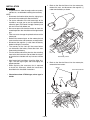
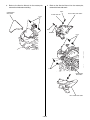
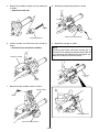
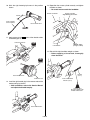
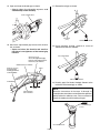
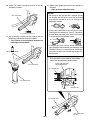
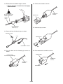
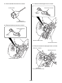
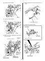
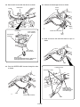
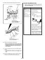
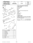
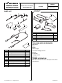
Accessory
INSTALLATION
INSTRUCTIONS
Application
Publication No.
MII 14476
HEATED GRIP ATTACHMENT
CTX700/D
P/N 08T70-MJF-A30
Issue Date
March 2013
HEATED GRIP KIT
Sold separately
PARTS LIST
(4)
(8)
(4)
(2)
(9)
(3)
(7)
(5)
(1)
(10)
(3)
(6)
(2)
No.
(1)
No.
Description
Installation Instruction URL
1
(2)
Heated grip harness
1
(3)
Wire tie (narrow)
2
(4)
Wire tie (medium)
5
(5)
Stay
1
(6)
Harness boot
1
(7)
Cushion
1
(8)
Wire tie (short)
2
(9)
Wire tie (long)
3
Tube
1
(10)
© 2013 Honda Motor Co., Ltd. - All Rights Reserved.
Qty
(1)
Right heated grip
1
(2)
Left heated grip
1
(3)
Controller
1
(4)
Owner’s Manual
1
TOOLS AND SUPPLIES REQUIRED
Side cutters
Ruler
Marker
Electrical tape
Pro Honda Handgrip Cement
Grease
Thread lock
Isopropyl alcohol
Shop towel
Qty
(1)
Description
TORQUE INFORMATION
Refer to the Service Manual for the torque values of the
removed parts.
1 of 12
87952-MJF-A300
1.
INSTALLATION
CAUTION
• To prevent burns, allow the engine, exhaust system,
radiator, etc., to cool before installing the accessory.
NOTE:
• Disconnect the throttle cables from the right grip as
instructed in the motorcycle’s Service Manual.
• For secure adhesion of the left heated grip to the
handlebar, we urge you to use the recommended
adhesive agent (Pro Honda Handgrip Cement) and
wait until it cures fully before use.
• Be sure to open and close the throttle to check for
smooth operation after installation of the right heated
grip.
• Take care not to damage the painted surfaces of the
motorcycle.
• Reinstall the removed parts on the motorcycle and
make sure that wires and harnesses are not pinched.
• Disconnect the negative (-) cable from the battery
before installing this accessory.
• The memory of the clock will be erased when
you disconnect the battery. Reset the clock after
reconnecting the battery.
• Trim the excess ends off the wire ties after attaching
them to the wire harnesses. Do not allow the cut part
of the wire tie to interfere with any harness or brake
hose.
• After heated grip installation, check the lights (e.g.
right / left turn signal lights and brake lights) for
proper operation.
• When replacing the accessory that is required
to install this accessory, follow the instructions
described in this installation instructions.
Refer to the Service Manual for the motorcycle,
remove the seat, and disconnect the negative (-)
cable from the battery as shown.
SEAT
BOLT
NEGATIVE (-) CABLE
2.
Refer to the Service Manual for the motorcycle,
remove the inner covers.
BOLTS
RIGHT INNER COVER
• Illustrations show CTX700 type, other type is
similar.
CLIPS
LEFT INNER COVER
2 of 12
3.
Refer to the Service Manual for the motorcycle,
remove the windscreen moulding.
4.
Refer to the Service Manual for the motorcycle,
remove the front side cowls.
BOLT
WINDSCREEN
MOULDING
RIGHT FRONT SIDE COWL
FLANGE COLLAR
CLIPS
BOLT
WASHER
CLIPS
CLIPS
CONNECTOR
Disconnect.
LEFT FRONT SIDE COWL
3 of 12
5.
Remove the handlebar weights from the motorcycle
as shown.
• Repeat on the left side.
8.
Remove the throttle housing cover as shown.
SCREW
THROTTLE HOUSING COVER
HANDLEBAR WEIGHT
SCREW
6.
Loosen the bolts and slide the master cylinder as
shown.
• Be careful not to scratch the handlebar.
9.
Remove the right grip as shown.
NOTE
Disconnect the throttle cable from the right grip as
instructed in the motorcycle’s Service Manual. Do not
try to disconnect the cable with force using pliers, etc.
Refer to the motorcycle’s Service Manual.
MASTER CYLINDER
RIGHT GRIP
(Save)
BOLTS
Loosen.
7.
Remove the right handlebar switch as shown.
SWITCH COVER
SCREW
THROTTLE CABLES
RIGHT HANDLEBAR SWITCH
4 of 12
10. Mark the right heated grip harness in the position
shown.
13. Reposition the master cylinder correctly and tighten
the bolts as shown.
• Be careful not to scratch the handlebar.
MASTER CYLINDER
150 mm
RIGHT HEATED
GRIP HARNESS
MATING SURFACE
Align with the punch mark.
RIGHT HEATED GRIP
MARKER
11. Apply grease to the
parts of the throttle cables
and throttle pipe as shown.
THROTTLE CABLES
BOLTS
TORQUE: 12 N·m
(1.2 kgf·m, 9 lbt·ft)
PUNCH MARK
GREASE
14. Reinstall the right handlebar weight as shown.
• Before applying a thread lock, thoroughly
clean the screw.
GREASE
SCREW
(Reuse)
RIGHT HEATED GRIP
THROTTLE PIPE
RIGHT HANDLEBAR
WEIGHT (Reuse)
12. Install the right heated grip in the reverse order of the
motorcycle’s grip removal.
• After installation, refer to the Service Manual
and adjust the throttle freeplay.
THREAD LOCK
Be sure to apply to the
threads of the screw.
RIGHT HEATED GRIP
5 of 12
15. Open and close the throttle grip as shown.
• Check that the throttle opens and
automatically closes smoothly.
17. Remove the left grip as shown.
RIGHT HEATED GRIP
LEFT GRIP
(Save)
ISOPROPYL ALCOHOL
16. Secure the right heated grip harness with the wire
ties as shown.
• Open and close the throttle and confirm
that there is no tightness of the heated grip
harness.
18. Using isopropyl alcohol, remove all traces of
adhesive from the left handlebar.
LEFT HANDLEBAR
WIRE TIE (narrow)
Secure the right heated grip
harness at the marked point to
the motorcycle’s harness.
MOTORCYCLE’S HARNESS
WIRE TIE (medium)
Secure the right
heated grip harness
to the handlebar.
MARK
ISOPROPYL ALCOHOL
HANDLEBAR
19. Liberally apply Pro Honda Handgrip Cement to the
inside of the left heated grip as shown.
40 mm
NOTE
Read the Instructions of the steps 19 through 22
carefully before installation and complete the operation
quickly before the adhesive cures. Use an assistant to
steady the motorcycle while installing the grip.
RIGHT HEATED
GRIP HARNESS
Pro Honda Handgrip
Cement
LEFT HEATED GRIP
6 of 12
20. Apply Pro Honda Handgrip Cement to the left
handlebar as shown.
22. Slide the left heated grip onto the left handlebar as
indicated.
• Wipe up excess adhesive at once.
NOTICE
• Do not tap on the grip end with a hammer and do
not twist the grip with force to insert the left heated
grip onto the handlebar, as it can damage the
heated grip element.
LEFT HANDLEBAR
• Avoid putting pressure on the switch part when
inserting the left heated grip. There is a possibility
that the switch will break. Also, install so that there
is no gap with the left handlebar switch.
Pro Honda Handgrip Cement
21. Spray isopropyl alcohol over the inside of the left
heated grip and outside of the left handlebar.
• This is done to ease alignment between the
heated grip and handlebar.
• If the grip gets stuck halfway during installation,
apply isopropyl alcohol between the heated grip and
handlebar. Do not try to remove the left heated grip
using force or tools as the heated grip element can
be damaged.
ISOPROPYL ALCOHOL
Insert until there is contact with the left handlebar
switch, then align with the indicated position.
Push in tight against the
left handlebar switch.
LEFT HANDLEBAR
LEFT HEATED GRIP
LEFT HEATED GRIP
HORN BUTTON
Align.
LEFT HEATED GRIP
LEFT HANDLEBAR
SWITCH
7 of 12
23. Reinstall the left handlebar weight as shown.
• Before applying a thread lock, thoroughly
clean the screw.
26. Connect the controller as shown.
HEATED GRIP
HARNESS
THREAD LOCK
Be sure to apply to the
threads of the screw.
CONTROLLER
SCREW
(Reuse)
LEFT HANDLEBAR
WEIGHT (Reuse)
27. Install the stay as shown.
24. Secure the fuse with electrical tape as shown.
ELECTRICAL TAPE
FUSE
CONTROLLER
HEATED GRIP HARNESS
STAY
25. Pass the boot over the heated grip harness as
shown.
28. Fit the boot over the controller as shown.
HARNESS BOOT
HARNESS BOOT
Pass the connector through.
HEATED GRIP
HARNESS
HEATED GRIP
HARNESS
CONTROLLER
8 of 12
29. Secure the boot with the wire tie as shown.
31. Connect the heated grip harness as shown.
HARNESS BOOT
HEATED GRIP HARNESS
CLIP (Reuse)
Install.
WIRE TIE (long)
Secure the harness boot.
30. Remove the dummy connector as shown.
DUMMY CONNECTOR
(Save)
CLIP
Remove.
MOTORCYCLE’S HARNESS
HEATED GRIP HARNESS
32. Route and secure the heated grip harness as shown.
HEATED GRIP HARNESS
MOTORCYCLE’S STAY
MOTORCYCLE’S HARNESS
CONNECTOR
Secure to the motorcycle’s stay.
9 of 12
33. Install the cushion as shown.
36. Slide the tube over the left heated grip harness as
shown.
CUSHION
TUBE
34. Install the controller as shown.
CONTROLLER
LEFT HEATED GRIP HARNESS
37. Connect each harness as shown.
LEFT HEATED
GRIP HARNESS
CUSHION
35. Route and secure the heated grip harness with the
wire ties as shown.
MOTORCYCLE’S HARNESS
HEATED GRIP
HARNESS
RIGHT HEATED
GRIP HARNESS
HEATED GRIP HARNESS
FRAME
WIRE TIE
Secure the heated
grip harness to
the motorcycle’
harness.
WIRE TIE
Secure the heated grip
harness to the frame.
ELECTRICAL TAPE
Wrap all connectors.
WIRE TIE
Secure the heated
grip harness to the
motorcycle’ harness.
10 of 12
38. Secure each harness with the wire tie as shown.
40. Connect the heated grip harness as shown.
HANDLEBAR
WIRES
(Green)
WIRE
(Blue)
HEATED GRIP HARNESS
HANDLEBAR
RIGHT HEATED
GRIP HARNESS
WIRE
(Blue)
HEATED GRIP
HARNESS
41. Slide and secure the tube with electrical tape as
shown.
LEFT HEATED
GRIP HARNESS
WIRE TIE (long)
Secure the heated grip harness, right and left
heated grip harnesses to the handlebar.
TUBE
39. Pass the HEATED GRIP harness through the tube
as shown.
RUBBER COLLAR
ELECTRICAL TAPES
Confirm that the
rubber collar is in
contact with the base
of the heated grip.
TUBE
HEATED GRIP HARNESS
TUBE
11 of 12
42. Secure each harness with the wire ties as shown.
DEALER TROUBLESHOOTING
• Stop the engine and turn the ignition switch OFF
when you check the parts and circuits other than
those of the heated grips.
HANDLEBAR
LEFT HEATED
GRIP HARNESS
Symptom
Check
Heated grip does not 1. Check whether wires and cables
(terminals and connectors) are
operate;
connected securely.
• Faulty heated grip
• Faulty heated grip 2. Heated grip inspection
coil
Check for resistance between the
terminals.
• Blown fuse
• Open or short circuit
in heater harness
Standard:
• Faulty heater switch
Left
Right : 2.2 ohms +/- 10%
: 2.2 ohms +/- 10%
HEATED GRIP
HARNESSES
WIRE TIE (medium)
Secure the heated grip
harnesses and left heated grip
harness to the handlebar.
3. Heater harness inspection:
Check for continuity.
4. If no abnormality is found after the
above checks 1, 2, and 3, but the
heated grip still does not operate
properly, replace the heater
switch with a new one.
• It is hard to check the switch with
ordinary inspection methods (for
continuity, voltage, etc.) because
it contains an integrated circuit.
HEATED GRIP
HARNESS
MOTORCYCLE’S
HARNESS
WIRE TIE (narrow)
Secure the heated grip harness to
the motorcycle’s harness.
43. Check each harness for sufficient play.
• Move the handlebar right and left and check
that the harnesses are not pinched by the
neighboring components and that they are
not pulled taut.
44. Install the motorcycle’s parts in the reverse order of
removal.
• Confirm that the harness is not caught or too
tight.
45. Move the handlebar right and left and check that this
accessory is not interfere with the motorcycle.
12 of 12