1
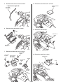
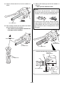
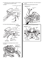
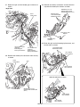
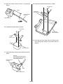
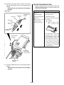
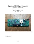
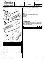
Accessory
Application
Publication No.
MII 14360
INSTALLATION
INSTRUCTIONS
HEATED GRIPS
GL1800B
P/N 08T70-MJG-670
Issue Date
March 2013
PARTS LIST
TOOLS AND SUPPLIES REQUIRED
Phillips ® screwdriver
Flat-tip screwdriver
Side cutters
Marker
Ruler
Honda Bond A (Pro Honda Handgrip Cement)
Thread lock
Grease
Isopropyl alcohol
Shop towel
Torque wrench
(8)
(2)
(3)
(5)
TORQUE CHART
(6)
Tighten all screws, bolts, and nuts to their specified
torque values. Refer to the Service Manual for the torque
values of the removed parts.
(1)
(4)
Item
4 mm screw
N·m
kgf·m
Ibf·ft
1
0.1
0.7
(9)
(10)
(7)
No.
(1)
Description
Installation Instruction URL
Qty
1
(2)
Heater switch
1
(3)
Left heated grip
1
(4)
Right heated grip
1
(5)
Heater switch stay
1
(6)
3 mm screw
2
(7)
4 mm screw
2
(8)
Wire tie
1
(9)
Right front shelter cover
1
Clamp
2
(10)
© 2012 Honda Motor Co., Ltd. - All Rights Reserved.
1 of 13
87951-MJG-6701
2.
INSTALLATION
CAUTION
• To prevent burns, allow the engine, exhaust system,
radiator, etc. to cool before installing the accessory.
NOTE:
• Disconnect the throttle cable from the right grip as
instructed in the motorcycle’s Service Manual.
• For secure adhesion of the heated grips use the
recommended adhesive agent (Honda Bond A, Pro
Honda Handgrip Cement) or equivalent.
• Be sure to open and close the throttle to check for
smooth operation after installation of the right heated
grip.
• Disconnect the negative (-) cable from the battery
before installing this accessory.
• After turning the ignition switch OFF, wait more than
10 seconds and then remove the negative (-) cable
from the battery.
• The memories of the tripmeter and clock will be
erased when you disconnect the battery. Reset the
clock after reconnecting the battery.
• Reinstall the removed parts on the motorcycle and
make sure that the wires and harnesses are not
pinched.
• Trim the excess ends off the wire ties after attaching
them to the wire harnesses. Do not allow the cut part
of the wire tie to interfere with another harness or
brake hose.
• After heated grip installation, check the lights (e.g.
right / left turn signal lights and brake lights) for
proper operation.
1.
Remove the left side cover, and disconnect the
negative (-) cable from the battery.
LEFT SIDE COVER
3.
4.
Also remove the right side cover.
Remove the motorcycle’s parts as shown.
RIGHT PASSENGER GRIP
BOLT
WASHER
LEFT
PASSENGER
GRIP
BOLT
BOLT
WASHER
WASHER
Open the left saddlebag lid as shown.
SEAT
FLANGE COLLAR
LEFT SADDLEBAG LID
2 of 13
5.
Remove the left cowl trim mould as shown.
• Repeat on the right side.
8.
Remove the front shelter cover as shown.
FRONT SHELTER
COVER
LEFT COWL
TRIM MOULD
6.
Remove the left front pocket as shown.
9.
Remove the indicated clips.
CLIP
SHELTER LID
Open.
LEFT FRONT
POCKET
CLIP
7.
Remove the motorcycle’s parts as shown.
RIGHT VISOR
RUBBER
LEFT VISOR
RUBBER
10. Remove the shelter lid as shown.
METER PANEL
Disconnect
the connector.
SHELTER LID
SCREW
KEY HOLDER
COVER
CLIP
FRONT
SHELTER
CENTER
3 of 13
11. Remove the motorcycle’s parts as shown.
13. Remove the motorcycle’s parts as shown.
BOLT
WASHER
RIGHT FRONT
SHELTER COVER (Save)
BOLT
WASHER
SCREW
HANDLE
CENTER COVER
METER
SCREW
BOLT
CLIP
RIGHT AIR CLEANER
INTAKE DUCT
SCREW
FRONT BRAKE
HOSE GUIDE
RIGHT SHELTER
SWITCH PANEL
Remove the cable.
12. Remove the right top shelter as shown.
SCREW
BOLT
14. Remove the right inner cover as shown.
RIGHT INNER COVER
SCREW
SCREW
RIGHT TOP SHELTER
RIGHT
FRONT FORK
CLAMP
NUT
CLIP
4 of 13
15. Remove the left handle cover as shown.
• Repeat on the right side.
17. Remove the screws from the right handle switch
holder as shown.
RIGHT HANDLE
SWITCH HOLDER
SCREW
SCREW
18. Remove the right grip as shown.
LEFT HANDLE COVER
16. Remove the handlebar weight from the motorcycle’s
right grip as shown.
• Repeat on the left side.
NOTE
Refer to the motorcycle’s Service Manual and
disconnect the throttle cable from the right grip as
instructed. Do not try to disconnect the cable with
force using pliers or other tools.
RIGHT GRIP (Save)
RIGHT HANDLE
SWITCH HOLDER
SCREW
RIGHT GRIP
HANDLEBAR WEIGHT
SCREW
THROTTLE
CABLE
5 of 13
19. Apply grease to the
parts of the throttle cables
and throttle pipe as shown.
THROTTLE
CABLE
21. Remove the screw and loosely install the clamp to
the right handle switch holder as shown.
GREASE
RIGHT HANDLE
SWITCH HOLDER
GREASE
CLAMP
SCREW
(Reuse)
RIGHT HEATED GRIP
22. Secure the right heated grip harness as shown.
THROTTLE
PIPE
RUBBER PART
20. Install the right heated grip and right handle switch
holder in the reverse order of the removal.
• After installation, refer to the Service Manual
and adjust the throttle freeplay.
RIGHT HEATED GRIP
RIGHT HANDLE
SWITCH HOLDER
RIGHT HEATED
GRIP HARNESS
SCREW
Tighten securely.
CLAMP
Secure the rubber part
of right heated grip
harness.
23. Twist the throttle grip as shown.
• Check for smooth opening of the throttle and
that it automatically snaps closed from any
opening, in all steering positions.
SCREW (Reuse)
RIGHT HEATED GRIP
6 of 13
24. Route the right heated grip harness as shown.
27. Using isopropyl alcohol, remove all traces of
adhesive from the left handlebar.
RIGHT HEATED GRIP
HARNESS
Route along the
motorcycle’s harness.
LEFT HANDLEBAR
ISOPROPYL ALCOHOL
28. Liberally apply the Honda bond A to the inside of the
left heated grip from the kit as shown.
NOTE
Read the Instructions of the Steps 28 through
31 carefully before operation and complete the
installation quickly before the adhesive agent cures.
Use an assistant to steady the motorcycle while
installing the grips.
25. Install the right handle cover in the reverse order of
removal.
26. Remove the left grip as shown.
<Left side>
Honda BOND A
LEFT Heated grip
LEFT GRIP (Save)
ISOPROPYL ALCOHOL
7 of 13
29. Apply the Honda bond A to the left handlebar as
shown.
31. Slide the left heated grip onto the left handlebar as
indicated.
• Wipe up excess adhesive at once.
NOTICE
• Do not tap on the grip end with a hammer and do
not twist the grip to install the heated grip onto the
handlebar, as it can damage the heating element.
• If the grip gets stuck halfway during installation,
apply isopropyl alcohol between the heated grip
and handlebar. Do not try to remove the heated
grip using force or tools as heating element can be
damaged.
Honda BOND A
LEFT HANDLEBAR
30. Spray isopropyl alcohol over the inside of the heated
grip and outside of the left handlebar.
• This is done to ease alignment between the
heated grip and the handlebar.
ISOPROPYL ALCOHOL
LEFT HANDLE
SWITCH HOLDER
LEFT HANDLEBAR
LEFT HEATED GRIP
Install the left heated grip in the position shown.
HEADLIGHT
DIMMER SWITCH
Align.
LEFT HEATED GRIP
LINE
LEFT HEATED GRIP
2.5 mm
8 of 13
LEFT HANDLE
SWITCH HOLDER
32. Remove the screw and loosely install the clamp to
the left handle switch holder as shown.
35. Install the left handle cover in the reverse order of
removal.
36. Install the front brake hose guide as shown.
<Left side>
LEFT HANDLE SWITCH HOLDER
FRONT BRAKE HOSE
GUIDE (Reuse)
BOLT (Reuse)
CLAMP
SCREW (Reuse)
33. Secure the left heated grip harness as shown.
Secure each harness in the position shown.
LEFT HANDLE
SWITCH HOLDER
FRONT BRAKE
HOSE GUIDE
RUBBER
PART
RUBBER
PART
RUBBER
PART
SCREW
Tighten securely.
LEFT HEATED
GRIP HARNESS
CLAMP
Secure the rubber
part of left heated grip
harness.
LEFT HEATED
GRIP HARNESS
34. Route the left heated grip harness as shown.
<Left side>
LEFT HEATED GRIP
HARNESS
Route along the
motorcycle’s harness.
9 of 13
RIGHT HEATED
GRIP HARNESS
37. Route the right and left heated grip harnesses as
shown.
39. Remove the dummy connectors and the electrical
tape from the motorcycle’s harness as shown.
<Right side>
MOTORCYCLE’S 2-PIN
WATERPROOF DUMMY
CONNECTOR (White) (Save)
MOTORCYCLE’S
2-PIN WATERPROOF
CONNECTOR (White)
RIGHT
FRONT FORK
ELECTRICAL TAPE
Remove.
MOTORCYCLE’S
HARNESS
40. Route the right and left heated grip harnesses, and
connect them as shown.
RIGHT HEATED GRIP
HARNESS
Route along the
motorcycle’s harness.
LEFT HEATED GRIP
HARNESS
Route along the
motorcycle’s harness.
2-PIN WATERPROOF
CONNECTOR (White)
LEFT HEATED
GRIP HARNESS
38. Remove the motorcycle’s connectors from the stay
as shown.
RIGHT
FRONT FORK
STAY
RIGHT HEATED
GRIP HARNESS
Route the harnesses as shown.
MOTORCYCLE’S 2-PIN
WATERPROOF CONNECTOR
(White)
RIGHT HEATED
GRIP HARNESS
LEFT HEATED
GRIP HARNESS
10 of 13
41. Secure the connected connectors to the stays.
43. Secure the right and left heated grip harnesses as
shown.
• Move the handlebar right and left and check
that the harnesses are not pinched by the
neighboring components and that they are
not pulled taut.
LEFT HEATED GRIP HARNESS
STAY
MOTORCYCLE’S WIRE TIE (Reuse)
Secure with the taped area of heated
grip harnesses and the taped area
of motorcycle’s harness aligned.
RIGHT HEATED
GRIP HARNESS
TAPE
42. Secure the right and left heated grip harnesses as
shown.
RUBBER
PART
44. Reinstall the right handlebar weight as shown.
• Repeat on the left side.
• Clean up with isopropyl alcohol before
applying thread lock.
• Be sure to apply threadlock to the threads of
the screw.
8 mm
CLAMP
Secure the rubber
part of right and
left heated grip
harnesses.
10 mm
SCREW (Reuse)
THREAD LOCK AREA
MOTORCYCLE’S WIRE TIE (Reuse)
Secure the right and left heated grip
harnesses to the motorcycle’s harness.
THREAD LOCK
RIGHT HEATED GRIP
HANDLEBAR WEIGHT
(Reuse)
11 of 13
SCREW
(Reuse)
45. Mark the heater switch harness in the position
shown.
48. Install the assembled heater switch as shown.
4 mm SCREW
110 mm
ASSEMBLED
HEATER SWITCH
HEATER SWITCH
HARNESS
HEATER SWITCH
MARKER
46. Assemble the heater switch as shown.
3 mm SCREW
RIGHT FRONT
SHELTER COVER
HEATER
SWITCH STAY
49. Install the right inner cover, right air cleaner intake
duct and right top shelter in the reverse order of
removal.
HEATER SWITCH
47. Secure the heater switch harness with the wire tie as
shown.
WIRE TIE
Secure the heater switch harness
at the marked point to the recess
of the heater switch stay.
HEATER SWITCH
HARNESS
MARK
HEATER SWITCH STAY
12 of 13
50. Connect the heater switch harness and install
the right front shelter cover in the reverse order of
removal.
• Confirm that any wire harness is not caught or
too tight.
DEALER TROUBLESHOOTING
• Stop the engine and turn the ignition switch OFF
when you check the parts and circuits other than
those of the heated grips.
Symptom
<Right side>
HEATER SWITCH
HARNESS
WIRE (Red)
Check
Heated grips do not 1. Check whether wires and cables
(terminals and connectors) are
operate;
connected securely.
• Faulty heated grip
WIRE (Black/
Green)
• Faulty heated grip coil 2. Heated grip inspection
• Blown fuse
• Open or short circuit
in heater harness
WIRE (Green)
• Faulty heater switch
WIRE (White/
Green)
Check for resistance between
the terminals.
Standard:
Right : 2.2 ohms +/- 10%
Left
: 2.2 ohms +/- 10%
MOTORCYCLE’S
HARNESS
3. If no abnormality is found after
the above checks 1 and 2, but
the heated grip still does not
operate properly, replace the
heater switch with a new one.
HEATER SWITCH
HARNESS
• It is hard to check the switch
with ordinary inspection
methods (for continuity, voltage
etc.) because it contains an
integrated circuit.
ASSEMBLED
RIGHT FRONT
SHELTER COVER
MOTORCYCLE’S
HARNESS
51. Install the motorcycle’s parts in the reverse order of
removal.
• Confirm that any wire harness is not caught or
too tight.
13 of 13