1
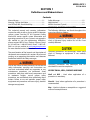
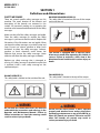
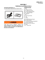
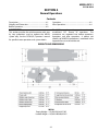
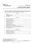
MES34-OPS-1
SPECIALTY HAULAGE SOLUTIONS FOR CONSTRUCTION AND MINING
Operators Manual
MEGA CORP.®
700 Osuna Rd. N.E. • Albuquerque, NM 87113 • 1-800-345-8889 • 505-345-2661 • Fax 505-345-6190
www.megacorpinc.com
® MEGA Corp., Inc. All Rights Reserved
MES34-OPS-1
21 Feb 2014
TABLE OF CONTENTS
Page
Section 1 Definitions and Abbreviations . . . . . . . . . . . . . . . . . . . . . . . . . . . . . . . . . . . . . . . . . . . . . . . . .1-1
Section 2 System Description. . . . . . . . . . . . . . . . . . . . . . . . . . . . . . . . . . . . . . . . . . . . . . . . . . . . . . . . . . . .2-1
Section 3 Limitations . . . . . . . . . . . . . . . . . . . . . . . . . . . . . . . . . . . . . . . . . . . . . . . . . . . . . . . . . . . . . . . . . . . .3-1
Section 4 Normal Operations . . . . . . . . . . . . . . . . . . . . . . . . . . . . . . . . . . . . . . . . . . . . . . . . . . . . . . . . . . . .4-1
Section 5 Performance . . . . . . . . . . . . . . . . . . . . . . . . . . . . . . . . . . . . . . . . . . . . . . . . . . . . . . . . . . . . . . . . . .5-1
Section 6 MES34 Operator’s Checklist. . . . . . . . . . . . . . . . . . . . . . . . . . . . . . . . . . . . . . . . . . . . . . . . . . . .6-1
A
MES34-OPS-1
21 Feb 2014
TABLE OF CONTENTS
B (Blank)
MES34-OPS-1
21 Feb 2014
SECTION 1
Definitions and Abbreviations
Contents
Manual Usage....................................................................1-1
Warning, Caution And Notes .......................................1-1
Use Of Shall, Will, Should And May............................1-1
Safety Messages ...............................................................1-2
Abbreviations....................................................................1-3
MES34 Overview (Typical) ............................................1-4
MANUAL USAGE
WARNING, CAUTION AND NOTES
This technical manual only contains information
required to safely install or service an MES34 elevator
scraper system. See the CAT 631 Operator’s Safety
Manual for tractor specific system information and
operating procedures. If your system is not covered in
this manual or you are experiencing difficulties,
please contact MEGA Corp. Product Support Group
at: US toll free: 1-800-345-8889, Direct: 1-505-3452661 or visit our website at www.megacorpinc.com
for more detailed contact information.
The following definitions are found throughout the
manual and apply as follows:
Operating procedures and techniques, which could
result in personal injury and/or loss of life if not
carefully followed.
Operating procedures and techniques, which could
result in damage to equipment if not carefully
followed.
The exact location of the hazards and description of
the hazards are reviewed in this section. All personnel
working on or operating the machine must become
familiarized with all the safety messages.
Operating procedures and techniques that are
considered essential to emphasize.
Due to the nature of these processes, ensure that all
safety information, warnings and instructions are
read and understood before any operation or any
maintenance procedures are performed. Some
procedures take place with heavy components and
at moderate heights, ensure proper safety
procedures are maintained when performing these
actions. Failure to use and maintain proper safety
equipment and procedures will cause injury, death or
damage to equipment.
USE OF SHALL, WILL, SHOULD AND MAY
Shall and Will – Used when application of a
procedure is mandatory.
Should – Used when application of a procedure is
recommended.
May - Used to indicate an acceptable or suggested
means of accomplishment.
1-1
MES34-OPS-1
21 Feb 2014
SECTION 1
Definitions and Abbreviations
SAFETY MESSAGES
BACKING RUNOVER HAZARD (2)
This safety label is located on the rear of the scraper
and inside the cab.
There are several specific safety messages on this
machine. The exact location of the hazards and
description of the hazards are reviewed in this
section. All personnel working on or operating the
machine must become familiarized with all the safety
messages.
Make sure that all of the safety messages are legible.
Clean the safety messages or replace the safety
messages in you cannot read the words. Replace the
illustrations if the illustrations are not legible. When
you clean the safety messages, use a cloth, water and
soap. Do not use solvent, gasoline or other harsh
chemicals to clean the safety messages. Solvents,
gasoline or harsh chemicals could loosen the
adhesive that secures the safety messages. Loose
adhesive will allow the safety messages to detach.
The vehicle is equipped with a back-up alarm.
Alarm must sound when operating this vehicle in
reverse. Failure to maintain a clear view in the
direction of travel could result in serious injury or
death.
Replace any safety message that is damaged or
missing. If a safety message is attached to a part that
is replaced, install a new safety message on the
replacement part.
FALL HAZARD (3)
This safety label is located at the top of the scraper.
DO NOT OPERATE (1)
This safety label is located on the outside of the cab.
Do not open this control box unless you read and
understand the instructions and warnings in the
Operator and Maintenance Manual. Failure to
follow instructions or heed the warnings could
result in serious injury or death.
Ensure PPE fall arrest harness is worn, adjusted
properly and attached to an anchor point when
performing maintenance on top of the MES34 or
when fall hazards are present. Failure to use PPE
when fall hazards are present may result in
serious personnel injury or death.
1-2
MES34-OPS-1
21 Feb 2014
SECTION 1
Definitions and Abbreviations
ABBREVIATIONS
HIGH PRESSURE MOTOR (4)
This safety label is located on the hydraulic motor.
ft - feet
fpm - feet per minute
gpm - gallons per minute
GET - Ground Engaging Tools
KM-H - Kilometers Hour
Kg - kilograms
l - liters
lpm - liters per minute
LT - Left
M - meters
MES - MEGA Elevating Scraper
MPH - Miles Per Hour
PPE - Personnel Protective Equipment
psi - pounds square inch
RPM - Revolutions Per Minute
RT - Right
SQ FT - Square Feet
Hydraulic motor and supply lines contain oil
under high pressure. Improper removal and
repair procedures could cause severe injury. To
remove or repair, instructions in the Maintenance
Manual must be followed.
1-3
MES34-OPS-1
21 Feb 2014
SECTION 1
Definitions and Abbreviations
MES34 OVERVIEW (TYPICAL)
3
9
1
4
5
2
SIDE VIEW
9
8
7
6
TOP VIEW
1
2
3
4
5
6
7
8
9
631G TRACTOR
DRAFT FRAME ASSEMBLY
ELEVATOR ASSEMBLY
SPILL GUARD
REAR BOGIE
ELEVATOR DRIVE MOTOR
SPEED DECREASER
FUEL TANK
IMPLEMENT VALVE
1-4
MES34-OPS-1
21 Feb 2014
SECTION 2
System Description
Contents
Description .........................................................................2-1
Scraper Bowl ......................................................................2-1
Rotating Floor....................................................................2-2
Elevator Assembly............................................................2-2
Rear Bogie Assembly ......................................................2-3
Draft Frame Assembly....................................................2-3
Electrical System ..............................................................2-4
Hydraulic System .............................................................2-4
Implement Joystick.........................................................2-5
Rear Brake System ...........................................................2-6
DESCRIPTION
SCRAPER BOWL
The MEGA 34 cubic yard elevating scraper (MES34) is
a high production unit, designed for heavy duty
continuous load/haul/spread operations. It is capable
of performing thin, precise lifts as well as heavy
excavation with little support equipment.
The scraper bowl has
a 34 cubic yard/26
cubic meter heaped
capacity for haulage
and an adjustable full
width cutting edge
for precise cutting
and heavy excavating.
The bowl cutting
edge is designed to
support a variety of Caterpillar Ground-Engaging
Tools (GET).
This new scraper bowl is combined with a currentproduction 631G scraper tractor and wheel groups to
provide the latest in power train, operator comfort,
electronic controls and emissions compliance. The
scraper bowl assembly design has been changed
from previously fielded systems to provide increased
reliability in severe duty applications.
The scraper bowl utilizes a
cellular
design
in
its
construction to add strength
and dent resistance to the bowl
sides. The cellular side wall
construction also provides for
mounting of several of the
moving and stationary bowl
components. These include the
rotating floor, elevator frame
mount arms, gooseneck draft
arm trunnions, bowl lift
cylinders, as well as rear bogie
assembly. Provisions are also available for optional
wear plates that increase bowl service life.
All scraper bowl assembly hydraulics, brakes,
electrical, controls, indicating and warning systems
are integrated into the existing 631G tractor control
groups.
The scraper bowl assembly is comprised of a scraper
bowl, rotating floor, elevator, rear bogie, wheel
groups and a draft frame assembly.
All hydraulic hoses and electrical cables for the rear
bogie functions are routed inside the right bowl wall
to the front of the bowl to eliminate the need for
component shielding. Rubber shrouds are installed
on the outer side walls to prevent wedging of
material between draft arms and outer bowl walls, in
turn protecting draft arms and trunnion ball mounts
from cracking.
2-1
MES34-OPS-1
21 Feb 2014
SECTION 2
System Description
ROTATING FLOOR
The frame incorporates draft arms which are used to
mount the assembly to the inside of the scraper
bowl. The draft arms, working in together with the
elevator adjusters, creates a mounting system that
protects the flights and cutting edge from rocks and
other large objects by swinging up, then quickly
returning back down to continue loading the bowl.
The rotating floor also utilizes a cellular design in its
construction for added strength and dent resistance.
Two large hydraulic cylinders connected to the j-link
rotate the door smoothly, allowing for precise
spreading of materials. The floor is designed with
close tolerances to the bowl for optimal material
removal, helping create a work alone piece of
machinery.
Elevator Adjusters
Draft Arm
J-Link
ELEVATOR ASSEMBLY
Elevator
Swing Up
The elevator assembly
conditions and loads
materials
into
the
scraper
bowl.
The
assembly consists of an
elevator frame and
draft arms, a speed
reducer,
sprockets,
chains, chain adjusters,
idlers and flights. The
upper corners of the
frame is designed with
a two piece steel casting that provides mounting for
the elevator drive system, as well as lever-type
elevator adjusters.
The flights are constructed of steel plates and
perform the actual conditioning and loading of the
materials. The flights are connected to dual drive
chains that are driven by a single high torque
hydraulic drive motor through the speed reducer.
2-2
MES34-OPS-1
21 Feb 2014
SECTION 2
System Description
REAR BOGIE ASSEMBLY
DRAFT FRAME ASSEMBLY
The bogie is a structural steel tube frame and plating
that mounts to the rear wall of the scraper bowl. The
assembly provides mounting for the rear wheel
groups, rear brake system, rotating floor cylinders
and tail lights. The rear of the bogie also incorporates
a push type bumper assembly.
The draft frame assembly is comprised of a
gooseneck, fuel tank and draft arms. This assembly,
along with two sets of hydraulic cylinders, is what
turns the unit and raises and lowers the bowl
assembly. The assembly also provides mounting for
implement control valve assembly, hydraulic
housing, electrical harnesses, protective guards and
work light.
The rear bumper design provides a pushing point to
assist the MES34 up a grade or in poor underfoot
conditions (wet, muddy or icy haul road). The
bumper assembly is designed to be pushed straight
on by the pushing (boosting) machine.
GOOSENECK
The gooseneck is made up of vertical hitch pin and
steering cylinder castings, a ½" top plate, ¾" side
plates and a 1½" bottom plate. The vertical hitch pin
attaches to the tractor and provides the pivot point
for the steering of the unit. The back side of the
gooseneck attaches to the fuel tank to create
mounting for the draft arms.
Routine HARD bumper contacts by the pushing
(boosting) machine will cause structural fatigue and
result in reduced bogie service life.
Angled blade contact of the bumper will reduce bull
dozer blade to MES34 wheel clearance. Extreme
blade angles will cause blade/bit to wheel contact
and damage MES34 tires. MES34 and pushing
(boosting) machine operators must communicate to
ensure correct contact and maximum wheel to
blade/bit clearance is maintained.
2-3
MES34-OPS-1
21 Feb 2014
SECTION 2
System Description
HYDRAULIC SYSTEM
FUEL TANK
The hydraulic power used to operate all scraper bowl
functions comes from several components mounted
on the tractor and bowl assembly. These components
consist of an auger pump, elevator drive motor,
implement pump, implement control value
assembly, bowl lift cylinders and floor cylinders.
Right-Hand
Side
AUGER PUMP (VARIABLE PISTON)
Left-Hand
Side
The fuel tank is constructed from a 26' mechanical
tube and two 1.5" thick flanges. The tank has a 250
gallon capacity with internal baffling to prevent
sloshing. The tank contains a fuel quantity sensor,
gravity fill port and the fast fill fuel system. The tank
also provides mounting for the draft arms,
implement control valve and the bowl lift cylinders.
The pump is mounted on the tractor transmission
accessory section and provides hydraulic power to
the elevator drive motor. The pump is a variable
displacement type pump with hydraulic output
being controlled by the tractor ECM.
DRAFT ARMS
The tractor ECM will maintain the operators selected
elevator speed within a desired range. This is
accomplished by ECM resident software designed to
control pump output based on a selected elevator
speed. See CAT Operator and Maintenance manuals
for more information.
The draft arms connect the draft frame to the bowl.
They are constructed from steel plates, mechanical
tube and cast steel trunnion bearings. The arms
connect at the trunnions and create a pivot point
between the draft frame and the bowl for raising and
lowering the cutting edge of the bowl.
ELEVATOR DRIVE MOTOR
The drive motor is
powered hydraulically
by the auger pump as
commanded by the
implement
joystick
thumb
switch.
The
motor is mounted to the
speed reducer that
drives the elevator upper sprocket assembly.
ELECTRICAL SYSTEM
The electrical system of the scraper bowl assembly is
fully integrated with the existing tractor systems.
These sub systems consist of all tail braking and turn
signal lights, implement controls and all brake
indicating and warning systems.
2-4
MES34-OPS-1
21 Feb 2014
SECTION 2
System Description
IMPLEMENT JOYSTICK
IMPLEMENT PUMP
The multi-section gear type pump mounted on the
tractor transmission accessory section. The pump
provides hydraulic power to the implement valve
assembly to operate floor and bowl lift systems as
commanded by the implement stick.
The joystick is located on the right side console and
provides controls for elevator, bowl, cushion hitch
and differential lock functions. See the CAT Operators
manuals for specific information pertaining to
cushion hitch and differential lock functions.
IMPLEMENT CONTROL VALVE ASSEMBLY
The implement control valve is
mounted to the fuel tank and
provides hydraulic control for
bowl, rotating floor and
elevator
functions
as
commanded by the implement
joystick. It also contains several
pressure sensors to provide
feedback for rotating floor auto
functions.
Implement
Joystick
BOWL LIFT CYLINDERS
The two bowl hydraulic cylinders
work together to raise and lower
the bowl assembly. The cylinders
are attached to the draft tube and
lower bowl edge. The cylinders
receive hydraulic pressure from the
implement control valve as
commanded by the implement
control stick.
FLOOR CYLINDERS
Implement Joystick function are as follows:
Floor Cylinders
1
J-link
Floor Cylinders
The two hydraulic cylinders work together to open or
close the bowl floor assembly. The cylinders are
attached to the J-link and the rear bogie.
2-5
Bowl Control (Joystick)
• Forward & Hold – lowers bowl.
• Rear & Hold – raises bowl.
• Releasing the joystick from a commanded
position will hold the bowl in the current
position.
MES34-OPS-1
21 Feb 2014
SECTION 2
System Description
2
3
4
6
AIR TANKS
The MES is equipped
with two air tanks
mounted in the rear
bogie that store 100150 psi air. The tanks
are interconnected and
receive pressurized air
from
the
tractor
primary air tank that is mounted under the tractor
cab. Each tank is equipped with drain port to remove
moisture from the brake system.
1st Push & Release – prevents the
transmission from shifting.
When the transmission hold is engaged, an
indicator light will illuminate on the front
dash.
2nd Push & Release – normal shifting is
resumed.
TANK PRESSURE SENDING UNIT
A 24 VDC pressure sending unit
is mounted on the rear bogie
and is wired into the existing
tractor brake pressure indicating
and warning systems. The
sending unit provides air
pressure sensing for the tractor
air brake sensing in the tractor
cab. The sending unit also
provides a signal to the brake low pressure warning
system that sounds an audible warning tone when
brake supply pressure drops below allowable limits.
Cushion Hitch (Inner Push Button)
•
•
The MES rear brake system consists of a wheel group,
two additional air tanks, pneumatic manifold
assembly, pneumatic brake relay valve, brake pods,
solenoid valve, pressure switch, pressure sending
unit and hosing.
Transmission Hold (Outer Push Button)
•
5
The MES rear brake system is integrated with the
existing 631G tractor parking, service and emergency
brakes. All three systems are activated with the
existing brake controls located in the tractor cab. See
the CAT 631G Operator and Service Manual for
additional tractor brake information.
Elevator Control (Thumb-switch)
• Left – elevator rotates to load.
• Right – elevator rotates to unload.
• Speed increases the further the thumb-switch
is moved from center.
• If a different elevator direction is desired with
“cruise control” on, elevator will delay for
about 3 seconds before reversing direction.
•
REAR BRAKE SYSTEM
Floor Control (Joystick)
• Left & Hold – opens floor fully.
• Right & Release – auto closes floor.
• Auto close can be interrupted by
commanding floor open and release.
1st Push & Release – enables cushion hitch.
2nd Push & Release – disables cushion hitch.
Elevator On/Off/Resume (Trigger Switch)
• Pull bottom of trigger – engages “cruise
control” and holds existing elevator direction
and speed selected by thumb switch. If speed
and direction was previously set, pulling the
trigger will reestablish previous settings.
• Push top of trigger – disengages “cruise
control”.
2-6
MES34-OPS-1
21 Feb 2014
SECTION 2
System Description
PNEUMATIC MANIFOLD ASSEMBLY
BRAKE PODS
A pneumatic cylinder
designed to extend or
retract and apply service,
parking or emergency
brakes. The pods are
mounted to the MES rear
bogie and are connected
to the wheel group brake activation lever. The pod
contains a coil spring and responds to pressure
received from the brake relay valve as commanded
by service brake pedal. The pod will also apply
parking or emergency brakes when one side of the
cylinder is depressurized when commanded by the
activation of the parking or emergency brakes. Loss
of pneumatic pressure allows the brake pod coil
spring to extend the rod end.
A pneumatic manifold mounted in the rear bogie
used to route pneumatic pressure for service, parking
and emergency brake operation. The manifold also
provides mounting for a check valve, parking brake/
emergency solenoid and parking brake pressure
switch.
CHECK VALVE
A spring operated valve allowing air flow in only one
direction. The valve is located with the pneumatic
manifold assembly in the rear bogie.
PARKING BRAKE THEORY OF OPERATION
The parking brake is applied by activating the
parking brake switch in the tractor cab. Once the
switch is moved to the park position an electrical
signal is sent to the parking brake solenoid valve
mounted on the rear bogie pneumatic manifold. The
sent signal will open the solenoid valve allowing
pneumatic pressure to decrease from one side of the
brake pod. The brake pod coil spring can now
overcome air pressure and extend the brake pod rod
end attached to the wheel group brake lever and
apply the brakes. Once parking brake pneumatic
pressure drops below allowable limits, the parking
brake pressure switch mounted on the pneumatic
manifold will close and illuminate the parking brake
warning light in the cab of the tractor.
PARKING/EMERGENCY BRAKE SOLENOID
A 24 VDC electrical solenoid that opens or closes to
control the parking or emergency brake function.
The solenoid valve responds to electrical signals as
commanded by the parking or emergency brake in
the tractor cab. The solenoid valve will open to bleed
off parking/emergency brake release pressure from
the brake pods. This release of air pressure will cause
the parking/emergency brakes to be applied.
PARKING BRAKE PRESSURE SWITCH
A 24 VDC pressure switch used to
illuminate the parking brake warning
light in the tractor cab. The sensor will
turn on the parking brake warning
light when parking brake release
pressure drops below allowable
limits.
The parking brake is released by activating the
parking brake switch. Once the switch is moved an
electric signal is sent to close the parking brake
solenoid valve. The valve closing will allow
pneumatic pressure from the pneumatic manifold to
be routed to the brake pod. This pressure increase
will eventually overcome the brake pod coil spring
and retract the brake pod cylinder rod end attached
to the brake pod releasing the brakes. As pressure
increases above allowable limits, the parking brake
pressure switch will turn off the parking brake
warning light in the tractor cab once pressure is
above allowable limits.
SERVICE BRAKE RELAY VALVE
A pneumatic relay valve that controls and routes air
tank activation pressure to both brake pods. The relay
controls air pressure applied to the brake pods as
commanded by a pneumatic signal pressure by
activating the service brake pedal located in the
tractor cab.
2-7
MES34-OPS-1
21 Feb 2014
SECTION 2
System Description
SERVICE BRAKE THEORY OF OPERATION
The service brake is applied by pressing down on the
service brake pedal in the tractor cab. Pressing down
on the pedal will send a pneumatic pressure signal to
the service brake relay valve mounted on the rear
bogie. The sent signal will release pneumatic
pressure from the brake pod chamber allowing the
pod coil spring to extend the rod end and apply
service brakes.
The service brake is released by releasing the brake
pedal. Once the pedal released a pneumatic signal is
received by the brake relay to increase air pressure to
the brake pod. As pneumatic pressure increases the
force of the brake pod coil spring is overcome and
the service brake is released.
EMERGENCY BRAKE THEORY OF OPERATION
The emergency brake theory of operation is the same
as the parking brake except for the means of
activation. Activation is accomplished by using the
emergency brake foot switch located on the floor of
the tractor cab just left of the service brake pedal.
2-8
MES34-OPS-1
21 Feb 2014
SECTION 3
Limitations
Contents
Gross Vehicle Weight .....................................................3-1
Operator’s Seat.................................................................3-1
Engine & Transmission.................................................. 3-1
GROSS VEHICLE WEIGHT
Do not exceed 195,656 lbs/80,80495 GVW.
OPERATOR’S SEAT
When you operate the machine in very rough ground
conditions or at travel speeds not suitable for the
ground conditions, this may result in excessive seat
vertical travel with impact of the suspension against
the travel stops, which may cause injury. Do not
operate the machine on ground conditions and at
travel speeds that could result in the seat suspension
travel stops being contacted. In order to minimize
impact loading on the operator, properly adjust the
seat controls based upon your weight and based
upon your height. Refer to the 631G Operation and
Maintenance Manual, "Seat" for more information.
ENGINE & TRANSMISSION
Do not allow the engine to overspeed when you go
downhill. Do not disengage the transmission while
you are travelling downhill. If equipped, use the
retarder control to reduce engine overspeed when
you are going downhill. If your machine is not
equipped with a retarder control, use the service
brake control to reduce engine overspeed when you
are going downhill. Never coast the machine.
3-1
MES34-OPS-1
21 Feb 2014
SECTION 3
Limitations
3-2 (Blank)
MES34-OPS-1
21 Feb 2014
SECTION 4
Normal Operations
Contents
Description .........................................................................4-1
Weights and Dimensions ..............................................4-1
Before Operations............................................................4-2
Operations..........................................................................4-2
After Operations...............................................................4-4
DESCRIPTION
The MES34 normal operating procedures mirror the
established CAT format of operations. The
procedures are separated into before operations,
operations and after operations. A pocket size
checklist of all MES34 procedures is contained in the
Appendix for use in the vehicle cab.
This section provides the vehicle operator with step
by step procedures used to operate the MES34
system only. See the CAT631(G) Operators' manual
for specific tractor operations and system details.
WEIGHTS AND DIMENSIONS
MES34
Empty Weight = 113,456 LBS/46,475 KG
Loaded Weight = 195,656 LBS/80,495 KG
4-1
MES34-OPS-1
21 Feb 2014
SECTION 4
Normal Operations
BEFORE OPERATIONS
18. Brake Air Tanks - DRAIN VALVES CLOSED
These procedures are used to perform a walk-around
inspection of the MES34 before use or beginning of
the shift. This inspection is in addition to and does
not replace the CAT 631G tractor inspection
requirements found in the 631G Operation &
Maintenance Manuals.
1. Chocks – As Required
19. LH Exterior Bowl Structure, Mud Flaps and Draft
Arm – DAMAGE AND SECURITY
20. Elevator Drive Motor and Speed Reducer –
DAMAGE, SECURITY AND LEAKS
OPERATIONS
2. Vehicle Parking Brake – ON
Use these procedures to safely operate the standard
and optional systems installed on the MES34.
3. Gear Selector Lever – “N” Neutral
1. Check for adequate clearance around the
machine.
4. Cab Control Switches – SET AS REQUIRED
5. Cab Windows – DAMAGE AND CLEANLINESS
Before you maneuver the machine, make sure
that no personnel are between the machine and
attachments. Pinch points and attachments will
cause serious injury or death.
6. LH Tractor – DAMAGE, SECURITY AND LEAKS.
7. Front of Tractor – DAMAGE, SECURITY AND
LEAKS.
2. Mirrors – ADJUST
8. Machine Kill Switch – OFF
3. Engine - START
9. Hydraulic Reservoir Level – CHECKED
4. Operators Seat – ADJUST
10. Machine Lock-out Switch - ON
11. RH Tractor – DAMAGE, SECURITY AND LEAKS
12. King Pin, Transmission and Gooseneck
DAMAGE, SECURITY, SERVICING AND LEAKS
Only operate the machine while you are in a seat
with a fastened seat belt. Only operate the
controls while the engine is running.
–
5. Steering Column – ADJUSTED
13. Fuel Tank, Gooseneck, Implement Valve
Assembly and Hosing – DAMAGE, SECURITY AND
LEAKS
6. Seat Belts – FASTNED
7. Bowl – RAISE
14. Bowl Cutting Edge, Lift Cylinders and Hosing –
DAMAGE, SECURITY AND LEAKS
8. Cushion Hitch – ENGAGE AS REQUIRED
15. Elevator Assembly, Floor Assembly and Bowl
Interior – DAMAGE AND SECURITY
Actuation of the cushion-hitch or steering control
can cause movement in the hitch area, reducing
clearances suddenly. Personal injury or death can
result from hitch movement if a person is in the
hitch area.
16. RH Exterior Bowl Structure, Mud Flaps and Draft
Arm – DAMAGE AND SECURITY
17. Rear Bogie, Tires and Floor Cylinders – DAMAGE,
SECURITY AND LEAKS
4-2
MES34-OPS-1
21 Feb 2014
SECTION 4
Normal Operations
the area is clear before you operate the machine
in the REVERSE position.
9. Service Brake Pedal – DEPRESS To prevent
machine from moving
10. Parking Brake – RELEASE
The cushion-hitch should be turned on at all
times except when you are loading materials or
when you are dumping materials. When the
cushion-hitch is turned OFF, depth of cuts will be
more even and material will spread more
smoothly during unloading. This will help you to
achieve faster cycle times.
11. Transmission Control Lever – MOVE TO DESIRED
DIRECTION AND APPROPRIATE GEAR SPEED
For operator comfort and maximum service life of
power train components, deceleration and/or
braking is recommended before any directional
shifts are made.
The elevator does not need to be running when
you are unloading fine material.
12. Service Brake – RELEASE
13. Throttle Pedal – DEPRESS UNTIL DESIRED ENGINE
SPEED IS ACHIEVED
Reduce engine speed when you maneuver in
tight quarters or when you are going over a hill.
14. Drive the machine forward in order to have the
best visibility and the best control.
Select the appropriate travel speed before you
begin to drive the machine downhill. Do not shift
the transmission control while you are going
downhill.
15. While you operate the machine slowly in an open
area, check for proper operation of all controls
and all protective devices.
When you operate the machine in very rough
ground conditions or at travel speeds not suitable
for the ground conditions, this may result in
excessive seat vertical travel with impact of the
suspension against the travel stops, which may
cause injury. Do not operate the machine on
ground conditions and at travel speeds that
could result in the seat suspension travel stops
being contacted. In order to minimize impact
loading on the operator, properly adjust the seat
controls based upon your weight and based
upon your height. Refer to the 631G Operation
and Maintenance Manual, "Seat" for more
information.
When you drive the machine downhill, use the
same gear speed that would be used to drive the
machine uphill.
Do not operate the machine when the parking
brake is applied.
Loading the machine in a straight line is
preferred.
Do not overload the bowl.
There is restricted visibility to the area directly
behind the machine. Failure to make sure the
area is clear could result in injury or death. Use a
second person on the ground to make sure that
Do not operate the machine without normal air
pressure.
4-3
MES34-OPS-1
21 Feb 2014
SECTION 4
Normal Operations
9. Lock all vandalism covers and all compartments.
Do not allow the engine to overspeed when you
go downhill. Do not disengage the transmission
while you are travelling downhill. If equipped, use
the retarder control to reduce engine overspeed
when you are going downhill. If your machine is
not equipped with a retarder control, use the
service brake control to reduce engine overspeed
when you are going downhill. Never coast the
machine.
AFTER OPERATIONS
Perform these procedures after the end of the shift or
end of the day. These steps are in addition to and do
not replace the CAT631G after operation
requirements established in the Operation and
Maintenance Manual.
1. Machine – STOPPED
2. Parking Brake – APPLIED
3. Gear Shift Lever - NEUTRAL
4. Engine – OFF
5. Inspect the engine compartment for debris.
Clean out any debris in order to avoid a fire
hazard.
6. Remove all flammable debris from the front
bottom guard through the access doors in order
to reduce a fire hazard. Discard the debris
properly.
7. Turn the key for the battery disconnect switch to
the OFF position. When the machine is left for an
extended period of one month or longer, you
should remove the key. This will help to prevent a
battery short circuit. Removing the key will also
help to protect the battery from vandalism and
from the current draw that is made by certain
components.
8. Perform a walk around inspection of the entire
machine looking for damage, security, leaks and
servicing.
4-4
MES34-OPS-1
21 Feb 2014
SECTION 5
Performance
Contents
Description ........................................................................5-1
Gradeability/Speed/Rimpull .......................................5-1
Retarding ........................................................................... 5-2
DESCRIPTION
This section contains MES34 performance data.
GRADEABILITY/SPEED/RIMPULL
631G Gross Weight
37.25R35 Tire
Figure 5-1: Gradeability/Speed/Rimpull
5-1
MES34-OPS-1
21 Feb 2014
SECTION 5
Performance
RETARDING
631 Gross Weight
Figure 5-2: Retarding
5-2
MES34-OPS-1
21 Feb 2014
SECTION 6
Appendix
MES34-OPS(CL)-1
21 Feb 2014
MES34
OPERATOR’S
CHECKLIST
6-1
MES34-OPS-1
21 Feb 2014
SECTION 6
Appendix
MES34-OPS(CL)-1
21 Feb 2014
TABLE OF CONTENTS
Title
Page
1. BEFORE OPERATIONS . . . . . . . . . . . . . . . . . . . N-2
2. OPERATIONS
3. AFTER OPERATIONS . . . . . . . . . . . . . . . . . . . . . N-14
N-1
6-2
MES34-OPS-1
21 Feb 2014
SECTION 6
Appendix
MES34-OPS(CL)-1
21 Feb 2014
BEFORE OPERATIONS
These procedures are used to perform a walk-around
inspection of the MES34 before use or beginning of
the shift. This inspection is in addition to and does
not replace the CAT 631G tractor inspection
requirements found in the 631G Operation &
Maintenance Manuals.
1. Chocks – As Required
2. Vehicle Parking Brake – ON
3. Gear Selector Lever – “N” Neutral
4. Cab Control Switches – SET AS REQUIRED
5. Cab Windows – DAMAGE AND CLEANLINESS
6. LH Tractor – DAMAGE, SECURITY AND LEAKS.
7. Front of Tractor – DAMAGE, SECURITY AND
LEAKS.
8. Machine Kill Switch – OFF
9. Hydraulic Reservoir Level – CHECKED
10. Machine Lock-out Switch - ON
N-2
6-3
MES34-OPS-1
21 Feb 2014
SECTION 6
Appendix
MES34-OPS(CL)-1
21 Feb 2014
11. RH Tractor – DAMAGE, SECURITY AND LEAKS
12. King Pin, Transmission and Gooseneck –
DAMAGE, SECURITY, SERVICING AND LEAKS
13. Fuel Tank, Gooseneck, Implement Valve
Assembly and Hosing – DAMAGE, SECURITY AND
LEAKS
14. Bowl Cutting Edge, Lift Cylinders and Hosing –
DAMAGE, SECURITY AND LEAKS
15. Elevator Assembly, Floor Assembly and Bowl
Interior – DAMAGE AND SECURITY
16. RH Exterior Bowl Structure, Mud Flaps and Draft
Arm – DAMAGE AND SECURITY
17. Rear Bogie, Tires and Floor Cylinders – DAMAGE,
SECURITY AND LEAKS
18. Brake Air Tanks - DRAIN VALVES CLOSED
19. LH Exterior Bowl Structure, Mud Flaps and Draft
Arm – DAMAGE AND SECURITY
20. Elevator Drive Motor and Speed Reducer –
DAMAGE, SECURITY AND LEAKS
N-3
6-4
MES34-OPS-1
21 Feb 2014
SECTION 6
Appendix
MES34-OPS(CL)-1
21 Feb 2014
OPERATIONS
Use these procedures to safely operate the standard
and optional systems installed on the MES34.
1. Check for adequate clearance around the
machine.
Before you maneuver the machine, make sure
that no personnel are between the machine and
attachments. Pinch points and attachments will
cause serious injury or death.
2. Mirrors – ADJUST
3. Engine - START
4. Operators Seat – ADJUST
Only operate the machine while you are in a seat
with a fastened seat belt. Only operate the
controls while the engine is running.
5. Steering Column – ADJUSTED
6. Seat Belts – FASTENED
7. Bowl – RAISE
N-4
6-5
MES34-OPS-1
21 Feb 2014
SECTION 6
Appendix
MES34-OPS(CL)-1
21 Feb 2014
8. Cushion Hitch – ENGAGE AS REQUIRED
Actuation of the cushion-hitch or steering
control can cause movement in the hitch area,
reducing clearances suddenly. Personal injury or
death can result from hitch movement if a person
is in the hitch area.
9. Service Brake Pedal – DEPRESS To prevent
machine from moving
10. Parking Brake – RELEASE
11. Transmission Control Lever – MOVE TO DESIRED
DIRECTION AND APPROPRIATE GEAR SPEED
For operator comfort and maximum service life
of power train components, deceleration and/or
braking is recommended before any directional
shifts are made.
12. Service Brake – RELEASE
13. Throttle Pedal – DEPRESS UNTIL DESIRED ENGINE
SPEED IS ACHIEVED
N-5
6-6
MES34-OPS-1
21 Feb 2014
SECTION 6
Appendix
MES34-OPS(CL)-1
21 Feb 2014
14. Drive the machine forward in order to have the
best visibility and the best control.
15. While you operate the machine slowly in an open
area, check for proper operation of all controls
and all protective devices.
When you operate the machine in very rough
ground conditions or at travel speeds not
suitable for the ground conditions, this may
result in excessive seat vertical travel with impact
of the suspension against the travel stops, which
may cause injury. Do not operate the machine on
ground conditions and at travel speeds that
could result in the seat suspension travel stops
being contacted. In order to minimize impact
loading on the operator, properly adjust the seat
controls based upon your weight and based
upon your height. Refer to the 631G Operation
and Maintenance Manual, "Seat" for more
information.
There is restricted visibility to the area directly
behind the machine. Failure to make sure the
area is clear could result in injury or death. Use a
second person on the ground to make sure that
N-6
6-7
MES34-OPS-1
21 Feb 2014
SECTION 6
Appendix
MES34-OPS(CL)-1
21 Feb 2014
the area is clear before you operate the machine
in the REVERSE position.
The cushion-hitch should be turned on at all
times except when you are loading materials or
when you are dumping materials. When the
cushion-hitch is turned OFF, depth of cuts will be
more even and material will spread more
smoothly during unloading. This will help you to
achieve faster cycle times.
The elevator does not need to be running when
you are unloading fine material.
Reduce engine speed when you maneuver in
tight quarters or when you are going over a hill.
Select the appropriate travel speed before you
begin to drive the machine downhill. Do not shift
the transmission control while you are going
downhill.
N-7
6-8
MES34-OPS-1
21 Feb 2014
SECTION 6
Appendix
MES34-OPS(CL)-1
21 Feb 2014
When you drive the machine downhill, use the
same gear speed that would be used to drive the
machine uphill.
Do not operate the machine when the parking
brake is applied.
Loading the machine in a straight line is
preferred.
Do not overload the bowl.
Do not operate the machine without normal air
pressure.
Do not allow the engine to overspeed when you
go downhill. Do not disengage the transmission
while you are travelling downhill. If equipped,
use the retarder control to reduce engine
overspeed when you are going downhill. If your
N-8
6-9
MES34-OPS-1
21 Feb 2014
SECTION 6
Appendix
MES34-OPS(CL)-1
21 Feb 2014
machine is not equipped with a retarder control,
use the service brake control to reduce engine
overspeed when you are going downhill. Never
coast the machine.
AFTER OPERATIONS
Perform these procedures after the end of the shift
or end of the day. These steps are in addition to and
do not replace the CAT631G after operation
requirements established in the Operation and
Maintenance Manual.
1. Machine – STOPPED
2. Parking Brake – APPLIED
3. Gear Shift Lever - NEUTRAL
4. Engine – OFF
5. Inspect the engine compartment for debris.
Clean out any debris in order to avoid a fire
hazard.
6. Remove all flammable debris from the front
bottom guard through the access doors in order
to reduce a fire hazard. Discard the debris
properly.
N-9
6-10
MES34-OPS-1
21 Feb 2014
SECTION 6
Appendix
MES34-OPS(CL)-1
21 Feb 2014
7. Turn the key for the battery disconnect switch to
the OFF position. When the machine is left for an
extended period of one month or longer, you
should remove the key. This will help to prevent a
battery short circuit. Removing the key will also
help to protect the battery from vandalism and
from the current draw that is made by certain
components.
8. Perform a walk around inspection of the entire
machine looking for damage, security, leaks and
servicing.
9. Lock all vandalism covers and all compartments.
N-10
6-11
MES34-OPS-1
21 Feb 2014
SECTION 6
Appendix
6-12 (Blank)