1
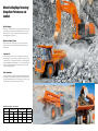
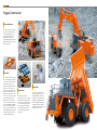
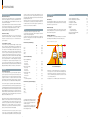
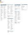
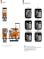
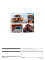
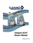
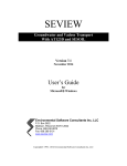
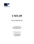
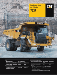
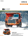
EH series
DUMP TRUCK
Model Code : EH1100-5
Nominal Payload with Standard Equipment : 63.5 tonnes (70.0 tons)
Target Gross Machine Operating Weight : 108 950 kg
Engine Rated Power : 567 kW (760 HP)
Hitachi Cutting Edge Technology
Brings Best Performance and
Comfort.
Hitachi Technology
Hitachi Trucks, like Hitachi Excavators are designed and manufactured using
cutting edge technology. Hitachi truck monitoring and control is performed
by Hitachi electronic components and software, resulting in excellent machine reliability and operator comfort.
High-Powered Engine Selection
Strong, reliable power is provided in by a choice of diesel powered engines. The EPA Tier 2 emission certified engines maintain a low fuel consumption level.
Long Frame Life
Frame rails are tapered from front to rear to distribute the load evenly over
the entire length of the chassis. In place of castings, hot rolled steel is used
as it is known to be more homogeneous and easier to repair. Weld joints are
oriented longitudinally to the principal flow of stress for strength and long life.
Proven design and manufacturing methods with state-of-the-art ultrasonic
testing ensure a quality product.
Unique Body Design
The single sloped floor evenly distributes material shedding during dumping.
Horizontal floor and side rail stiffeners distribute load shocks evenly over the
entire body length, minimizing stress concentrations in any one area. Closely
spaced floor stiffeners reduce wear due to impact loading.
Well Matched: EH1100- 5 & Excavators
Excavator
ZX870LCH -5 (BH)
EX1200 -6 (BH)
EX1200 -6 (LD)
Boom
7.1 m - BE Boom 8.4 m - H Boom
9.0 m - Boom 7.55 m - BE Boom
-
Arm
2.95 m - BE Arm
3.7 m - H Arm
3.6 m - Arm
3.4 m - BE Arm
-
Bucket Capacity
*4.3 m3
*3.5 m3
*5.2 m3
*6.7 m3
6.5 m3
Passes
8 or 9
10 or 11
7
5 or 6
5 or 6
BH : Backhoe
LD : Loading shovel *SAE, PCSA heaped capacity
Rugged Construction
Technologically Advanced
The EH1100-5 is designed to develop
low cycle times and extra efficiency
in the heavy duty applications of
quarrying and mining. This truck
provides low operating costs,
unparalleled productivity and overall
quality through its superior structure
and systems design.
Robust Frame
Full fabricated box section main rails
with section height tapered from front
to rear. Narrow at the rear to support
the load and wider at the front
allowing truck stability and excellent
engine access for servicing. One
piece top and bottom flanges that
eliminate cross member tie in joints
and provide a large exposed center
area for access to major components.
Large radii at frame junctions are
blended and ground to minimize
stress concentrations. Weld joints are
oriented longitudinally to the principal
flow of stress for greater durability
and more strength. Frame utilizes 345
MPa yield high strength low alloy steel
that is robotically welded to ensure
consistently high quality welds.
400 BHN high-tensile steel
Hydraulic Brake
Reinforced Body
Built for quarry and mining
applications, the EH1100-5 body uses
an 18 mm floor plate and 8 mm side
plates made of 400 BHN high-tensile
steel. This provides high resistance
to wear and impact. A low loading
height and large target area allow
easy, quick loading by a variety of
loading tools.
The rear wet disc brake assemblies
have been upgraded to include
spring applied pistons that function
to provide a strong, reliable and low
maintenance integral parking brake.
The Hitachi hydraulic braking system
is durable and provides maximum
available braking under tough ground
conditions for best control.
Spindle
Superior Suspension
Ease of Operation
The Hitachi ACCU-TRAC suspension
system delivers excellent maneuverability,
even at higher speeds. The trailing arm layout offers greater ease of servicing while
improving truck performance compared
to suspended king-pin designs. The pivot
mounting of the trailing arm design allows
only axial input to the strut and allows
wheel movement in the vertical plane only.
Features:
Lateral forces that act on the front
wheels are minimized, resulting in reduced
tire scuffing.
Dynamic friction (side-wall force) within
the strut is low due to the features of the
ACCU-TRAC design, allowing the use of a
lighter strut engineered to a smaller
diameter and longer stroke.
The necessary frame bulk (horse-collar
structure) needed to mount a suspended
king-pin is non-existent.
The elimination of the “horse-collar”
member provides greater engine access.
The NEOCON strut used with the ACCUTRAC suspension, improves operator and
component isolation, provides better
hauler stability and predictable operational
control.
Locating the king-pin close to the wheel
assembly and at a slight angle results in
low “Dry Park Steering” effort.
Development of the compressible media,
NEOCON-E™ fluid (silicon based, nonpetroleum) for use in the suspension strut
with Helium gas, results in an improved
energy absorption (isolation) system and
an improved energy release (stability)
system that responds favorably whether
traveling empty or with payload in a wide
range of ambient temperatures.
Hi-Tech ROPS / FOPS Cab
The new Hi-TECH (Hitachi Technology) ROPS/FOPS cab
features a 265 mm (10.4") LCD screen positioned to the right
of the steering wheel to provide better visibility of the road
ahead.
The cab uses double-wall construction and a 3-point rubber
isolation-mount to absorb shocks and noise. The high
powered heater and air conditioning unit provides operator
comfort in all environments and working conditions.
The central controller, built by Hitachi and also used in
excavators, will perform its function of processing input and
output information with reliability during the most rigorous
haul cycle.
Both Struts at normal height
King-Pin
Retains the spindle to the trailing arm. Spindle
rotates around the king-pin, which is locked in
position. The Neocon-E strut attaches to the
top.
Trailing Arm
Both struts in compression
Main suspension member to which other suspension components are attached. The trailing
arms hinge on a torque tube that is clamped to
the front of the frame.
Neocon Strut
Drivers Side Strut in compression,
other strut in extension
The energy absorption and release component
of the ACCU-TRAC suspension system. Pinned
to ball bushings at the frame and at the top of
the king-pin to prevent bending moments from
transferring to the strut. Receives only axial
input.
With no horizontal deflection
Trailing Arm Suspension (Front)
The ACCU-TRAC suspension design allows the front struts to be removed and installed without removing the trailing arms,
brakes or tires. This relates to fewer tools
and less labour required to perform the
repair, which aims to reduce the amount of
hauler downtime, increasing productivity.
Auto-Lubrication System
A ground level accessible grease pump assembly automatically
feeds lubricant to grease points throughout the truck via
plumbing. The lubricant is delivered in time controlled and
metered quantities to all connected lube points in the system.
Hitachi equips the EH1100-5 with a Lincoln Auto-Lubrication
system. Control, timing and monitoring of the Lincoln system is a
function of the Hitachi central controller.
Each spindle is controlled by a hydraulic steering cylinder, rotates around the king-pin and
the outer end of the trailing arm to position the
wheels for steering. The spindles are attached
by one tie-rod.
NEOCON Strut (Front/Rear)
Helium gas
NEOCON-E TM fluid
Impact
Auto Lubricator
SPECIFICATIONS
ENGINE
DRIVE AXLE
WEIGHTS (Approximate)
Model�������������������������
Type���������������������������
Emission Certification�
Aspiration�������������������
Rated Power
SAE J1995, gross��
SAE J1349, net������
ISO 9249, net���������
EEC 80/1269, net��
Maximum Torque�������
Piston Displacement���
Bore and Stroke���������
Torque Rise����������������
Starting����������������������
Cummins QSK23
4 Cycle Inline 6, diesel injection
U.S. E.P.A Tier 2
Turbocharged / Aftercooled
Model Differential��������� 2354
Axle Design����������������� Full floating axle shafts using a model 2354 differential
and single reduction planetaries at each wheel
Traction Control���������� An optional electronic feature that includes the
Electronic Downhill Speed Control feature
567 kW (760 HP) at 2 100 min-1(rpm)
520 kW (698 HP) at 2 100 min-1(rpm)
520 kW (698 HP) at 2 100 min-1(rpm)
520 kW (698 HP) at 2 100 min-1(rpm)
3 091 N·m (315 kgf·m) at 1 300 min-1(rpm)
23.0 L
170 x 170 mm
20 %
Electric
Differential and Final Drive Ratios
Ratios
Differential
Planetary
Total Reduction
Maximum Speeds
with 24.00R35 tires
Model�������������������������
Type���������������������������
Emission Certification�
Aspiration�������������������
Rated Power
SAE J1995, gross��
SAE J1349, net������
ISO 9249, net���������
EEC 80/1269, net��
Maximum Torque�������
Piston Displacement���
Bore and Stroke���������
Torque Rise����������������
Starting����������������������
MTU Detroit Diesel 12V Series 2000
4 Cycle, V12, diesel injection
U.S. E.P.A Tier 2, E.U. Stage II*
Turbocharged / Aftercooled
Front��������������������������� 24.00 R35(**) E4 (Radial) [Standard]
Rear���������������������������� 24.00 R35(**) E4 (Radial) [Standard]
Rim Width������������������� 432 mm (17 in)
Alternative tires and tread patterns may be available.
Note:
Certain job conditions may require higher rated TKPH (TMPH) tires in
order to maintain maximum production. Hitachi recommends evaluating
the job conditions and consulting the tire manufacturer to make proper
tire selection.
567 kW (760 HP) at 2 100 min-1(rpm)
520 kW (698 HP) at 2 100 min-1(rpm)
520 kW (698 HP) at 2 100 min-1(rpm)
520 kW (698 HP) at 2 100 min-1(rpm)
3 091 N·m (315 kgf·m) at 1 350 min-1(rpm)
23.9 L
130 x 150 mm
20 %
Electric
ELECTRICAL SYSTEM
24 volt starting, lighting and accessories system. 75 ampere alternator
with integral transistorized voltage regulator. Two 12 V heavy duty
batteries capable of 1425 cold cranking amps, each, at -18 degree C (0
degree F). A Hitachi solid state reprogrammable controller controls and
monitors hauler systems, provides output information to control gauges
and lights and incorporates connections for diagnostic tools.
TRANSMISSION
The transmission employs Shift Energy Management (SEM) which
reduces engine torque during transmission shifts resulting in longer
drivetrain life and increased operator comfort.
Additionally an Optimum Start Range feature has been engineered for
the EH1100-5. This feature provides reduced fuel use, less noise and more
operator comfort during unloaded truck operation. When the automatic
onboard payload weighing system identifies an unloaded body, the
transmission is activated to start the upshifting sequence from 3rd gear.
BODY CAPACITY
Struck (SAE)
Heap 3 : 1
Heap 2 : 1 (SAE)
km/h
9.7
14.5
19.4
28.9
Gear
5
6
R1
R2
Ratio
1.00
0.67
5.12
3.46
m3
32.7
38.2
41.5
Body capacity and payload subject to change based on customer
specific material density, options and application.
Model�������������������������� Allison H6620A
Design������������������������� Fully automatic, planetary type with integral
lock-up converter
Mounting/Position������� Remote from engine and rear axle for serviceability
Ranges����������������������� 6 forward, 2 reverse
Control������������������������ Allison CEC3 electronics shift system with
SEM (Shift Energy Management) and OSR
(Optimum Start Range)
Ratio
4.00
2.68
2.01
1.35
58.2 km/h
TIRES
*Fuel optimized version is available.
Gear
1
2
3
4
3.64 : 1
5.80 : 1
21.11 : 1
BRAKE SYSTEM
Net machine weight stated below includes standard equipment.
Net machine weight changes will directly affect the Nominal Payload.
Brake system complies with ISO 3450 (SAE J1473).
All-hydraulic actuated braking system providing precise braking control
and quick system response. The Hitachi brake controller has a unique
variable front to rear brake proportioning that maximizes the stopping
performance under all road conditions.
Chassis with Hoist 34 260 kg
Body
11 190 kg
Net Machine Weight
45 450 kg
The Net Machine Weight specification includes operator and 100 % fuel.
Nominal Payload 63.5 tonnes
Target GMOW
108 950 kg
Service
All-hydraulic actuated front dry disc brakes and rear oil-cooled wet disc
brakes are equipped.
The Nominal Payload specification is calculated using the Hitachi Loading
Policy. Specific job site requirements may result in an adjustment to the
Nominal Payload weight.
Consult your Hitachi dealer for a truck configuration which will match
your haulage application.
Major Options
The following list of options are examples which will change the
Nominal Payload.
Automatic Fire Suppression
Body Liner, heavy duty and partial
Deck Mounted Muffler
Weight Distribution
Empty
Loaded
Front
50 %
34 %
Wet Disc Brake
The Hitachi wet disc brake is engineered for long service life even in
the most extreme environments. The wet disc brakes are located on
the rear axle and provide service braking, secondary braking, retarding
and parking. The brakes are a multi-plate design, and continuously oilcooled. The sealed design protects against environmental contamination
for prolonged service life. The wet disc brake is designed with automatic
retraction to prevent drag and with spring activation for parking. Separate
pedals activate the service braking and retarding functions.
Front Axle - Dry Disc
Disc diameter each (2 discs/axle)
Brake surface area per axle
Lining area per axle
Brake pressure (Max.)
Rear
50 %
66 %
STEERING SYSTEM
Rear Axle - Oil-Cooled Wet Disc
Brake surface area per axle Brake pressure (Max.)
Closed-center, full-time hydrostatic steering system using two double-acting
cylinders, pressure limit with unload piston pump and brake actuation/
steering system reservoir. An accumulator provides supplementary steering
in accordance with ISO 5010 (SAE J1511). The Operators steering wheel
offers 35 degrees of tilt and 47.7 mm of telescopic travel.
Steering Angle
Turning Diameter: (SAE)
Steering Pump Output (at 2 100 min-1(rpm)
System Pressure
39 degrees
19.85 m
94.7 L/min
19.0 MPa
Wet Disc Parking Brake
The parking brake is internal to the rear wet disc brakes.
Retarder
Foot-operated valve controls all-hydraulic actuation of oil-cooled wet
disc brakes on rear axle. System provides modulated pressure to rear
brakes for constant speed control.
Continuous
656 kW
(880 HP)
Intermittent
1 270 kW
(1 700 HP)
HYDRAULIC SYSTEM
Body Raise Travel
Body Raise Time (at 2100 min-1(rpm))
Body Down Time (at idle)
Brake Cooling Pump Output (at 2100 min-1(rpm))
Hoist Pump Output (at 2100 min-1(rpm))
System Relief Pressure (Hoist)
64 605 cm2
4.8 MPa
Secondary
Two independent circuits within the service brake system provide backup stopping capability. Manually application of this system will stop the
machine within prescribed braking distance. Automatic application will
result if supply pressure is low and the operator has failed to react to
indicators and alarms.
Two 2-stage, double-acting cylinders, with cushioning in retraction,
inverted and outboard mounted. Separate Hoist/Brake Cooling reservoir
and independent tandem gear pump. Control valve mounted on reservoir.
km/h
39.0
58.2
7.6
11.3
686 mm
7 316 cm2
2 787 cm2
15.9 MPa
59 degrees
11.4 seconds
14.2 seconds
176 L/min
468 L/min
17.2 MPa
Load/Dump Brake Apply
Through activation of a switch by the operator, a solenoid is energized,
sending full brake pressure to apply the rear Wet Disc brakes. For use
during the load and dump cycles.
SPECIFICATIONS
resistance to bending and torsional loads while eliminating unnecessary
weight. The unique ACCU-TRAC independent trailing arm suspension
absorbs haul road input, minimizing suspension-induced frame twisting while
providing independent tire action.
NEOCON ride struts are mounted with spherical bushings, eliminating
extreme sidewall forces by ensuring a purely axial input to the ride strut.
The wide track stance of the ACCU-TRAC suspension system and the long
wheel base assure a more stable, comfortable ride.
HI-TECH ROPS / FOPS CAB
Hi-Tech ROPS / FOPS Cab
The EH1100-5 ROPS system complies to ISO 3471: 2008 for the rigid dump
truck and tractor configurations. The cab also complies with FOPS ISO
3449: 2005. Multilayered floor mats and wall panels act to absorb sound
and control interior temperature.
A properly maintained cab from Hitachi, tested with doors and windows
closed per work cycle procedures in ISO 6394: 2008 (dBA), results in an
operator sound exposure Leq (Equivalent Sound Level) of 75 dB(A).
A three-point rubber iso-mount arrangement to the deck surface
minimizes vibration to the operator compartment.
BODY
The body has been made to the single slope, flat floor design.
The rear hinge has been designed to allow the hinge pin to float when
the body is in the fully lowered position.
The weight of the body and payload is distributed across rubber body
pads that are evenly spread across the length of the body rail-box that
rests on the truck frame.
Excellent Serviceability
A removable front panel allows easy access to service brake valves,
retarder valve and heater assembly. A removable cover located behind
the operators’ seat provides easy access to electrical and electronic
system components.
HITACHI LOADING POLICY
SERVICE CAPACITIES
Operational Benefits
Crankcase (includes filters) for MTU
Crankcase (includes filters) for Cummins
Cooling System for MTU
Cooling System for Cummins
Transmission, Cooler and Lines
Fuel Tank
Hydraulics
Hoist Tank and System
Steering Tank and System
Drive Axle (2 wheels and differential)
Windshield Washer Fluid
Haulroad Safety
Truck loading within the limitations of the Hitachi Loading Policy will
result in designed and certified operational performance of the steering,
brake and ROPS systems of the truck.*
Efficient Productivity
Truck loading within the limitations of the Hitachi Loading Policy will
result in optimizing the fuel economy and travel speed performance to
which the truck was designed to.*
Availability and Maintenance
Lower maintenance costs and higher availability can be achieved if
truck loading is within the limitations of the Hitachi Loading Policy.*
*Hitachi recommended maintenance is required.
Plate Thickness (Standard Body):
Comfort and Ease of Operation
A 265 mm (10.4") LCD screen is positioned slightly to the right of steering
wheel to provide better visibility through the front cab window and to
prevent the steering wheel spokes from causing visual obstruction. The
LCD is pleasant to view in all lighting conditions and incorporates large
interactive buttons to toggle to various monitor selections within close
reach of the operator. Conventional gauges and lights are replaced
by computer generated graphics that perform the same purpose of
providing truck system performance information with trouble conditions
supported by messages in text as secondary. The pass-through cab
offers a spacious environment. The interior design allows the operator
to exit through the left or right side doorway, making either one of the
access stairways easily available to the operator. Multiple position
adjustable seat, tilt/telescopic steering wheel, filtered cab ventilation and
high ground visibility all contribute to convenience, control and comfort.
Floor
Front
Sides
Canopy
Valley
mm
18
10
8
6
8
(in)
(0.69)
(0.38)
(0.31)
(0.25)
(0.31)
10
6
10
(0.38)
(0.25)
(0.38)
Options for Standard Body:
Body Liners (Medium Duty)
Floor & Valley
Sides & Front
End Protection Body Liners (Heavy Duty)
Floor & Valley
Sides & Front
End Protection Partial Liner (Heavy Duty)
Floor & Valley
End Protection Rock Cap
Top of the Body Side Plate
SUSPENSION
Front and Rear Suspension
For years, Hitachi haulers have enjoyed an industry-wide reputation for
superior suspension systems. That experience and knowledge has now
been pushed to the next level, to develop the truly advanced ACCU-TRAC
suspension for the EH1100-5. To make sure it was fine tuned to the limit,
Lotus Engineering, a world leader in suspension design, was contracted to
review the entire system to assure optimized ride and handling performance.
13
8
10
(0.50)
(0.31)
(0.38)
13
10
(0.50)
(0.38)
10
(0.38)
25
16
14
8
(1.00)
(0.63)
(0.55)
(0.31)
More than
90% of
Loads
100%
Max.
10% of
Loads
110%
No
Loads
120%
Percent of Nominal Payload
1: More than 90% of all loads must fall below 110% area (Orange area).
2: If necessary due to excessive variation in material density, loader
bucket fill-factors or bucket sizes, loading the truck to between 110%
and 120% of Nominal Payload is allowed if it accounts for less than
10% of all loads (Yellow area).
3: Loading above 120% of Nominal Payload is not allowed. (Red Area)
Plate Thickness (Optional Quarry Body):
The ACCU-TRAC suspension system features independent trailing arms for
each front wheel with NEOCON struts, containing energy absorbing gas and
compressible NEOCON-E™ fluid, mounted between the king pins and the
frame. This arrangement allows a wider front track that provides a better ride,
improved stability and a reduced turning circle. The rear axle housing has an
A-frame mounting. The rear NEOCON struts are mounted in a more vertical
position which allows a more pure axial loading and reduces the tractive and
braking forces transmitted to the nose cone.
Floor
Front
Sides
Canopy
Valley
16 (0.63)
NEOCON struts outperform competitive strut designs by improving isolation,
stability, and control. Improved isolation means reduced impact loading
on the structural members of the machine and greater operator comfort,
resulting in longer equipment life and increased productivity. Improved
stability means more consistent dynamic response of the machine to
fluctuating load energy, resulting in predictable machine performance.
Improved control means better machine maneuverability.
The horizontal stiffener design of the Hitachi
body minimizes stress concentrations in any
one area. Load shocks are dissipated over
the entire body length.
The closely spaced floor stiffeners provide
additional protection by minimizing distance
between unsupported areas.
The Hitachi frame and ACCU-TRAC suspension system are designed
to work in unison to provide maximum structural integrity and operator
comfort. The fabricated rectangular frame rail construction provides superior
10
11
L
83.3
70.0
335
147
93.3
700
265
112
103
5.7
EQUIPMENT
CAB
Access, left and right side doors
Air conditioning
Air filtration/replaceable element
Air suspension seat *
Cab interior light
Camera monitor, within operators LCD
Comfort shift, Optimum Start
Range, when empty
Cup holders x 4
Data logging unit (DLU)
Door locks
Foot rest, left
Fuses
GPS communication
Heater and defroster
Hill Hold
lntegral ROPS/FOPS cab
lntegrated engine diagnostics connector
lntegrated transmission diagnostics
connector
STANDARD EQUIPMENT
GENERAL
Access system, step ladder drivers
side and service side
ACCU-TRAC suspension system
All-hydraulic braking
Allison H6620A transmission
Battery disconnect switch, ground
level
Body down cushioning
Body down indicator
Body up, reverse inhibit
Body up speed restriction
Canopy spill guard
Continuous heated body
Cooling system sight gauge
Cooling system surge tank
DC -DC , 24 to 12V converter
Driveline guard, front
Electric horns
Electric start
Electronic hoist
Engine belt protection
Engine idle timer
Fan guard
Fenders
5 piece rims
Fluid drain valves
Fluid sampling ports
Fixed steering stops
Front brake cut-off switch
Front corner mirrors
Fuel tank level gauge
Ground level auxiliary start (boost)
receptacle
Ground level engine shutdown
Guard rails
Hoist interlock
Hoist tank sight gauge
ISO decals
Load/dump brake
Lube system, Lincoln automatic
Mirrors, left and right, hand
adjustable
Mud flaps
NEOCON-E suspension struts
Park brake interlock
Payload weighing system, automatic
Radiator grille guard
Rear view camera system
Reverse alarm and light
Rock ejector bars
Steering accumulator
Steering tank sight gauge
Tires 24.00 R35
Tow points, front
Transmission oil level sensor
Transmission oil level sight gauge
Two speed reverse
Water separator included in fuel
filter
lSO driver envelope
LCD operator information screen,
265 mm (10.4")
Mechanical RHS and LHS windows
Parking brake test feature,
automatic
Quick connect hydraulic test ports
Rubber floor mat
Safety glass
Seat belts, retractable
(operator and trainer)
Speakers, antenna and wiring only
Sunvisor, pull-down
Tilt/telescoping steering wheel
Tinted glass, all windows
Trainers seat
12V power port
12 volt accessory connection
Windshield washer
Windshield wiper, intermittent
*Features
Parking brake alarm: Audible when parking brake not applied and
operator is not seated
Seat belt alarm: Audible and visible when truck is running and seat belt
is not buckled
3 point seat belt : Standard
ELECTRONIC DISPLAY (Hitachi Monitoring lnformation)
Lights with lSO symbols
LCD Screen Information
Active Traction Control with
Brake oil pressure
Speed Limiter
Brake oil temperature
Battery charge
Date and time
Body up
Engine coolant temperature
Brake system oil pressure
Engine oil pressure
Central warning (stop)
Filter restrictions
Central warning (yellow caution)
Fuel gauge
Electronic downhill speed
Haultronics III payload information
control (optional)
Hourmeter
Engine coolant level
Load Count
Engine oil pressure
Odometer
Filter restrictions
Parking brake applied
High beam
Selectable units of measure
Parking brake
Speedometer
Payload meter and number
Steering oil pressure
Retarder temperature
Steering oil temperature
Seat belt disconnected
System diagnostics
Steering oil pressure
Tachometer
Transmission oil temperature
Transmission oil temperature
Turn signal/ hazard
Transmission range attained
Transmission range selection
Trip Odometer
Voltmeter
MACHINE LIGHTS
LED amber turn signals and
four-way flashers
LED back-up light
12
OPTIONAL EQUIPMENT
CAB
Air suspension seat, semi-active,
w/ heat, w/ lumbar*
AM-FM radio w/ CD & Aux. input
OPTIONAL EQUIPMENT WEIGHT
LHS arm guard
Body liners (400BHN) plates, medium
Body liners (400BHN) plates, heavy duty
Body liners (400BHN) plates, partial
Lube system, Groeneveld
Rock Cap
Side Extensions
Canopy spill guard extension
Circuit Breakers in place of fuses
Electric RHS and LHS power
windows
Orbcomm communication
*Features
Parking brake alarm: Audible when parking brake not applied and
operator is not seated
Seat belt alarm: Audible and visible when truck is running and seat belt
is not buckled
3 point seat belt : Standard
Standard and optional equipment may vary from country to country. Special
options provided on request. All specifications are subject to change without notice.
CHASSIS
Body liners (400BHN) plates,
medium, heavy duty or partial
Canopy spill guard extension
Cold weather package
Mild cold weather package
(0 deg C to -20 deg C)
(32 deg F to -4 deg F)
Extreme cold weather package
(-20 deg C to -35 deg C)
(-4 deg F to -31 deg F)
Custom bodies available
Electrically heated mirrors
Engine access step
Engine side panels, for dust / dirt
protection
GPS communication, e-Service
LHS arm guard
Lube system, Groeneveld
Muffler, frame mounted, exhaust
flow to rear of chassis
MISCELLANEOUS
Extra operators manual
Extra parts manual - CD
Extra parts manual - hardcopy
kg
56
2 850
3 680
2 430
100
269
485
99
Rear driveline guard
Rock cap
Service center with fast fuel
Service center without fast fuel
Service lighting, engine,
transmission, service deck (4)
Side extensions
Side Mudguards, mounted to cab
deck
Side view camera (RHS)
Spare rim
Steering accumulator, region Canada
Tires (type & rating)
TranSyndTM transmission fluid
Variable pitch fan (Cummins)
Wheel chocks
Work lights, forward facing –LED
Work lights, rear facing –LED
Service Manual - CD
Service Manual - hardcopy
LED head lights (4)
LED brake/retarder lights (2)
13
DIMENSIONS
PERFORMANCE DATA
unit : mm
-
-
-
-
-
-
-
-
-
-
--
-
--
--
-
-
--
-
-
GRADE IN %
-
-
-
-
-
-
-
-
--
--
-
-
-
-
--
--
-
-
-
-
-
-
-
30
40
VEHICLE SPEED
40
45
0
50
--
20
35
-
50
10
30
2
-
25
--
20
4
6TH
--
RIMPULL
GRADE IN %
-
--
-
15
-
--
--
-
-
RIMPULL
GRADE IN %
-
-
--
--
10
-
--
-
-
-
-
-
-
5
6
5TH
--
-
--
-
--
--
-
-
-
-
--
-
-
-
-
-
-
--
--
--
-
-
--
--
-
-
-
-
-
--
-
-
--
4TH
NOTES:
60
70
80
Diagonal lines represent total resistance (Grade % plus rolling resistance %).
Charts based on 0 % rolling resistance, standard power of engine, standard tires and gearing unless otherwise stated.
1. Find the total resistance on diagonal lines on right-hand border of rimpull or retarder chart.
15
GRADE IN %
-
-
-
-
-
-
-
-
-
-
---
---
--
8
-
km/h 0
10
2ND
3RD
GRADE IN %
RIMPULL
GRADE IN %
RIMPULL
RIMPULL
9 090
RIMPULL
-
3 960
-
4 200
-
80
-
4 650
-
70
(mph) 0
12
1ST
-
60
-
50
80
14
-
40
VEHICLE SPEED
45
-
30
-
20
40
-
50
10
35
-
0- 0-
30
70
-
0
25
0
50
60
VEHICLE SPEED
-
0- 0-
20
45
250
100
kg x 1 000
100 150 200 250 300 350 400 450 500 (lb x 1 000)
20
Target
RETARDER CHART
18
NMW
EH1100-5
GMOW
Grade Length 1 500 m 5 000 ft
16
50
3010-
15
40
VEHICLE WEIGHT
40-
2
10
40
50-
105
30
60-
100- 20-
(mph) 0
20
35
2
70-
4
6TH
-
5TH
50
10
30
-
4TH
100- 20-
6
200-
25
-
8
20
4
6TH
-
2ND
3RD
40-
15
6
5TH
-
10
300-
10
-
1ST
50-
5
-
12
lb
x
1 000
8
4TH
-
14
60-
( ) 00
10
2ND
3RD
400- 9080-
16
70-
12
40-
100-
18
RETARDER CHART
EH1100-5
Grade Length 900 m 3 000 ft
-
50-
-
-
-
-
Target
GMOW
NMW
-
-
50
kN
80
1ST
km/h 0
250
100
kg x 1 000
100 150 200 250 300 350 400 450 500 (lb x 1 000)
20
0
50
14
60-
(mph) 0
VEHICLE WEIGHT
45
70
-
80
-
70
50
-
60
VEHICLE SPEED
40
60
-
50
35
250
100
kg x 1 000
100 150 200 250 300 350 400 450 500 (lb x 1 000)
20
Target
RETARDER CHART
18
NMW
EH1100-5
GMOW
Grade Length 600 m 2 000 ft
16
-
45
-
40
40
50
40
30
VEHICLE SPEED
-
30
35
25
30
30-
-
50
20
30
-
25
20
20
-
20
15
10
-
-
200-
10
2. Follow the diagonal line downward and intersect the NMW or GMOW weight line.
3. From intersection, read horizontally right or left to intersect the rimpull or retarder curve.
4. Read down for machine speed.
14
2
-
-
-
15
-
200-
10
10
400- 9080-
km/h 0
Note: Dimensions shown are for empty machine with standard body and 24.00R35(**)E4 tires.
Exact dimensions may vary due to tire make, type, and inflation pressure.
-
5
-
( ) 00
300-
4
6TH
70-
0- 0-
-
4 190
300-
0
lb
x
1 000
6
5TH
VEHICLE WEIGHT
100-
0- 0-
6TH
5
400- 9080-
10-
-
9 870
2 910
5TH
lb
x
1 000
2
-
4 280
630
6
( ) 00
10-
-
3 490
2 670
2 590
-
8
4TH
30-
570
-
10
2ND
3RD
100-
720
2 803
kN
100- 20-
kN
51
-
12
40-
km/h 0
1 810
-
-
50-
(mph) 0
4 610
8
4TH
(mph) 0
4
6 790
10
2ND
3RD
40-
km/h 0
1ST
-
5 060
50
80
14
60-
100- 20-
8 890
45
70
70-
30-
5 340
-
-
200-
50-
0- 0-
250
100
kg x 1 000
50 100 150 200 250 300 350 400 450 500 (lb x 1 000)
20
RETARDER CHART
Target
18
NMW
5
EH1100GMOW
Grade Length 450 m 1 500 ft
16
-
100-
400- 9080300-
30
35 40
50
60
0
VEHICLE WEIGHT
-
lb
x
1 000
25
40
VEHICLE SPEED
-
( ) 00
5
10
15 20
10
20
30
-
-
km/h 0
kN
-
(mph) 0
2 920
12
1ST
10-
0- 0-
4 420
60-
100- 20-
10-
655
1 420
14
70-
30-
5
-
100- 20-
200-
-
30-
300-
-
10
40-
50
-
50-
-
15
250
100
kg x 1 000
100 150 200 250 300 350 400 450 500 (lb x 1 000)
20
Target
RETARDER CHART
18
NMW
EH1100-5
GMOW
Grade Length Continuous
16
-
100-
20
Target
GMOW
VEHICLE WEIGHT
400- 9080-
7060-
lb
x
1 000
-
x 1 000 )
( ) 00
-
kN
-
320 360 400 ( lb
25
PERFORMANCE CHART
EH1100-5
@ 567 kW 760 HP
NMW
kg x 1 000
-
-
120 160 200 240 280
150
-
200-
-
300-
100
-
400- 9080-
-
80
VEHICLE WEIGHT
-
40
50
-
100-
-
lb
x
1 000
-
( ) 00
-
kN
--
3 950
-
4 240
Before using a machine with a satellite communication system, please make sure that
the satellite communication system complies with local regulations, safety standards
and legal requirements. If not so, please make modifications accordingly.
Hitachi Construction Machinery Co., Ltd.
www.hitachi-c-m.com
These specifications are subject to change without notice.
Illustrations and photos show the standard models, and may or may not include optional equipment,
accessories, and all standard equipment with some differences in color and features.
Before use, read and understand the Operator’s Manual for proper operation.
KR-EN044P
14.04 (KA / KA, FT3)
Printed in Japan