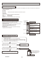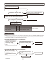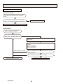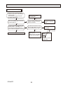
1
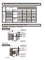
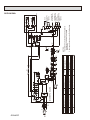
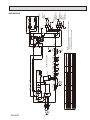
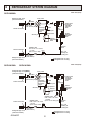
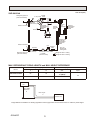
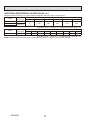
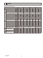
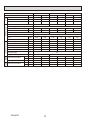
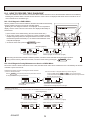
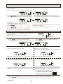
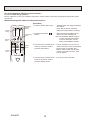
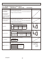
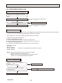
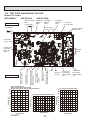
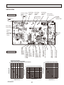
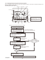
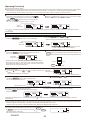
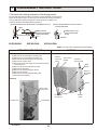
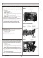
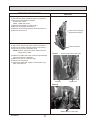
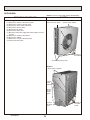
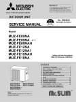
SPLIT-TYPE, HEAT PUMP AIR CONDITIONERS
May 2014
No.OCH467
REVISED EDITION-C
HFC
utilized
R410A
SERVICE MANUAL
R410A
Outdoor unit
[Model Names]
SUZ-KA09NA
SUZ-KA12NA
SUZ-KA15NA
SUZ-KA18NA
[Service Ref.]
SUZ-KA09NA.TH
SUZ-KA12NA.TH
SUZ-KA15NA.TH
SUZ-KA18NA.TH
Revision:
• Modified some contents in
10.TROUBLESHOOTING in
REVISED EDITION-C.
• Some other descriptions have
been also modified.
• Please void OCH467
REVISED EDITIN-B.
Note:
This service manual describes
service data of the outdoor units
only.
• RoHS compliant products have
<G> mark on the spec name plate.
CONTENTS
SUZ-KA18NA.TH
1. COMBINATION OF INDOOR AND OUTDOOR UNITS...2
2. PARTS NAMES AND FUNCTIONS....................2
3. SPECIFICATION.................................................3
4. OUTLINES AND DIMENSIONS..........................4
5. WIRING DIAGRAM............................................ 5
6. REFRIGERANT SYSTEM DIAGRAM................8
7. DATA.................................................................11
8. ACTUATOR CONTROL....................................13
9. SERVICE FUNCTION.......................................14
10. TROUBLESHOOTING......................................14
11. FUNCTION SETTING.......................................32
12. DISASSEMBLY INSTRUCTIONS.....................35
PARTS CATALOG (OCB467)
1
COMBINATION OF INDOOR AND OUTDOOR UNITS
Outdoor unit
Heat pump type
Indoor unit
Service Ref.
Service
Manual No.
SUZKA09NA.TH
KA12NA.TH KA15NA.TH
Heat pump without
electric heater
SEZ-KD09NA4.TH
SEZ-KD12NA4.TH
SEZ-KD15NA4.TH
HWE08020
SEZ-KD18NA4.TH
SLZ-KA09NA.TH
SLZ-KA12NA.TH
SLZ-KA15NA.TH
2
—
OCH487
OCB487
—
OUTDOOR UNIT
SUZ-KA12NA
—
—
—
—
—
—
—
—
—
—
—
—
—
—
SUZ-KA15NA
Air inlet
(back and side)
Drain hose
Air outlet
Drain outlet
SUZ-KA18NA
Air inlet
(back and side)
Piping
Drain hose
Air outlet
Drain outlet
OCH467C
—
—
Piping
OUTDOOR UNIT
—
—
PARTS NAMES AND FUNCTIONS
SUZ-KA09NA
KA18NA.TH
2
—
3
SPECIFICATION
SUZ-KA12NA
SUZ-KA15NA
SUZ-KA18NA
208/230 , 1 , 60
15
12
12
12
14
0.50
0.93
KNB073FQDHC KNB092FQAHC
SNB130FQBH
R.L.A
6.6
6.6
7.4
10.0
Compressor
L.R.A
8.2
8.2
9.3
12.5
Refrigeration oil oz. (Model)
10.8 (NEO22)
15.2 (NEO22)
Refrigerant control
Linear expansion valve
Cooling
dB(A)
46
49
49
54
1
Sound level*
Heating
dB(A)
50
51
51
56
Defrost method
Reverse cycle
W
in
31-1/2
33-1/16
Dimensions
D
in
11-1/4
13
H
in
21-5/8
33-7/16
Weight
Ib
66
77
80
119
External finish
Munsell 3Y 7.8/1.1
VDC
12 - 24
Control voltage (by built-in transformer)
Refrigerant piping
Not supplied
in
1/4 (0.0315)
Refrigerant pipe size Liquid
(Min. wall thickness) Gas
in
3/8 (0.0315)
1/2 (0.0315)
Indoor
Flared
Connection method
Outdoor
Flared
ft
40
50
Between the indoor & Height difference
outdoor units
Piping length
ft
65
100
Refrigerant charge (R410A)
1 lb. 16 oz.
2 lb. 9 oz.
3 lb. 16 oz.
Outdoor unit model
Power supply
Max. fuse size (time delay)
Min. circuit ampacity
Fan motor
Model
V , phase , Hz
A
A
F.L.A
SUZ-KA09NA
Note: Test conditions are based on AHRI 210/240.
*1 Rating conditions
(Cooling) — Indoor: 80˚F D.B., 67˚F W.B., Outdoor: 95˚F D.B., (75˚F W.B.)
(Heating) — Indoor: 70˚F D.B., 60˚F W.B., Outdoor: 47˚F D.B., 43˚F W.B.
OPERATING RANGE
(1) POWER SUPPLY
Rated voltage
Outdoor unit
OCH467C
208/230 V
1 phase
60 Hz
Guaranteed voltage (V)
Min. 187
3
208
230
Max. 253
4
OUTLINES AND DIMENSIONS
SUZ-KA09NASUZ-KA12NA SUZ-KA15NA
Unit: inch
REQUIRED SPACE
11/16
Air in
. or
4 in
4 in
. or
2- 3/8
7/8
13/16 Oval hole
re
29/32
11-1/4
8 in
17/32
5-7/8
2
Liquid pipe
Gas pipe
11-29/32
5-15/16
or m
ore
:1/4 (flared)
:3/8 (flared) (KA09/12)
1/2 (flared) (KA15)
6-23/32
19-11/16
31-1/2
2-23/32
SUZ-KA18NA
Open as a rule 20 inches or more
if the front and both sides are open
REQUIRED SPACE
4 inches or more/8 inches
or more if there are
obstacles to both sides
11-25/32
2-19/32
1-9/16
2
Air in
1-11/32
20-9/32
4 in
14-3/16
Air in
13
in.
Open two sides of left,
right, or rear side.
11-1/32
13/32
14
re
mo
. or
handle
Drain 3 holes
(ø1-5/16)
e
mor
mo
1-9/16
Air out
21-5/8
Basically open 4 inches or more
without any obstruction in front
and on both sides of the unit.
1-5/8
13-9/16
Drain hole
Air in
12 ~ 12-3/4
1-3/4
15-3/4
. or
mo
re
14
Air out
19-11/16
33-1/16
3-3/16
Open as a rule
20 inches or more if the back,
both sides and top are open
8-11/32
OCH467C
4
2-9/16
3-9/16
35°
30°
16-15/16
33-7/16
4-25/32
4-3/8 × 13/16 slot
Liquid:1/4(flared)
Gas :1/2(flared)
in.
or m
ore
OCH467C
5
IPM
U
V
W
P
N
INVERTER P.C. BOARD
LDW
LDV
LDU
TR821
MS
3~
MF
3
CN932
F901
3
1
IC932
t°
1
RT68
t°
RT65
CN643
3 1
BLU
YLW
t°
2 1
t°
RT61 RT62
CN641
4 1
RT68
NAME
OUTDOOR HEAT EXCHANGER
TEMP. THERMISTOR.
TERMINAL BLOCK
TB1,TB2
SWITCHING POWER TRANSISTOR
TR821
T801
TRANSFORMER
X63,X64,X66 RELAY
21S4
REVERSING VALVE COIL
HEATER PROTECTOR(OPTION PARTS)
26H
t°
SYMBOL
RT64
21
5
5
CN644
CN931
CN642
1
IC802
NAME
SYMBOL
NAME
LEV
EXPANSION VALVE COIL
SMOOTHING CAPACITOR
DIODE MODULE
MC
COMPRESSOR
FUSE (T3.15AL250V)
MF
FAN MOTOR
DEFROST HEATER(OPTION PARTS) PTC64,PTC65 CIRCUIT PROTECTION
INTELLIGENT POWER DEVICE
DEFROST THERMISTOR
RT61
RT62
DISCHARGE TEMP.THERMISTOR
INTELLIGENT POWER MODULE
FIN TEMP.THERMISTOR
REACTOR
RT64
AMBIENT TEMP.THERMISTOR
LED
RT65
CN61
RED
WHT
BLK
1
3
F801
T801
L61
LEV
M
6
CN724
LED
LD61
F701
LD63
3
4
1
LD62
PTC65
PTC64
X64
X63
21S4
LD-S
LD-E1
CN721
2
BRN
BLU
RED
BLK
YLW
2
2
BLK
BLK
H
26H
(OPTION PARTS)
BLK
BLK
BLK
BLK
S3
S2
S1
TB2
From INDOOR UNIT
CONNECTING WIRES
DC12-24V
TO INDOOR UNIT
CONNECTING WIRES
208/230V
1 phase 60Hz
From INDOOR UNIT
CONNECTING WIRE
GROUND
TB1 CIRCUIT
BREAKER
POWER SUPPLY
L2
208/230V
L1
1 phase 60Hz
1
1
1
1
2
2
NOTES:
1. About the indoor side electric wiring refer to
the indoor unit electric wiring diagram
for servicing.
2. Use copper conductors only. (For field wiring).
6
X66
1
CN722
BLK
RED
SUZ-KA09NASUZ-KA12NA
SYMBOL
C62,C63
DB61,DB65
F701,F801,F901
H
IC802
IPM,IC932
L61
LED
W RED 3
MS V WHT
3~
BLK
MC U
1
LD66
LD70
–
DB61
DB65 ~
– ~
~ C63 C62
+
+ +
~
+
ORN
SUZ-KA09NA, SUZ-KA12NA WIRING DIAGRAM
BLU
BRN
5
WIRING DIAGRAM
OCH467C
6
SYMBOL
C61,C62,C63
DB61,DB65
F701,F801,F901
H
IC802
IPM,IC932
L61
LED
CN61
RED
WHT
BLK
1
3
IPM
U
V
W
P
N
INVERTER P.C. BOARD
LDW
LDV
LDU
TR821
NAME
SYMBOL
LEV
SMOOTHING CAPACITOR
DIODE MODULE
MC
FUSE (T3.15AL250V)
MF
DEFROST HEATER(OPTION PARTS) PTC64,PTC65
INTELLIGENT POWER DEVICE
RT61
INTELLIGENT POWER MODULE
RT62
REACTOR
RT64
LED
RT65
W RED 3
MS V WHT
3~
BLK
MC U
1
3
1
IC932
T801
NAME
EXPANSION VALVE COIL
COMPRESSOR
FAN MOTOR
CIRCUIT PROTECTION
DEFROST THERMISTOR
DISCHARGE TEMP.THERMISTOR
FIN TEMP.THERMISTOR
AMBIENT TEMP.THERMISTOR
MS
3~
MF
CN932
3
F801
F901
LD66
LD70
–
DB61
~
DB65
– ~
+
~ C63 C62 C61
+ + +
~
+
SUZ-KA15NA WIRING DIAGRAM
t°
1
RT68
t°
RT65
CN643
3 1
5
BLU
YLW
t°
RT61 RT62
t°
2 1
CN641
4 1
RT68
NAME
OUTDOOR HEAT EXCHANGER
TEMP. THERMISTOR.
TERMINAL BLOCK
TB1,TB2
TR821
SWITCHING POWER TRANSISTOR
TRANSFORMER
T801
X63,X64,X66 RELAY
REVERSING VALVE COIL
21S4
HEATER PROTECTOR(OPTION PARTS)
26H
t°
21
5
CN644
CN931
L61
SYMBOL
RT64
CN642
1
IC802
ORN
LED
6
LD61
F701
LD63
3
4
1
LD62
PTC65
PTC64
X64
X63
LD-S
LD-E1
CN721
2
BLK
BLK
2
2
BLK
H
26H
(OPTION PARTS)
BLK
BLK
BLK
BLK
BLK
TB2
From INDOOR UNIT
CONNECTING WIRES
DC12-24V
TO INDOOR UNIT
CONNECTING WIRES
208/230V
1 phase 60Hz
From INDOOR UNIT
CONNECTING WIRE
GROUND
TB1 CIRCUIT
BREAKER
POWER SUPPLY
L2
208/230V
L1
1 phase 60Hz
1
1
1
1
2
2
S3
BLU S2
BRN S1
RED
YLW
NOTES:
1. About the indoor side electric wiring refer to
the indoor unit electric wiring diagram
for servicing.
2. Use copper conductors only. (For field wiring).
LEV
M
6
CN724
X66
1
CN722
21S4
RED
BLU
BRN
SUZ-KA15NA
OCH467C
7
C61,C62,C63
DB61,DB65
F701,F801,F901
H
IC802
IPM, HC930
L61
LED
SYMBOL
LDW
LDV
LDU
P
N
IPM
U
V
W
NAME
TR821
~
1
+
+
SYMBOL
CN931
+
MF
3~
3
5
MS
CN932
3
NAME
F801
F901
YLW
5
C63 C62 C61
LD66
L61
1
IC802
t°
1
RT64
t°
RT65
RT68
NAME
t°
CN641
4 1
RT61 RT62
t°
2 1
CN643
3 1
SYMBOL
RT68
CN644
INVERTER P.C. BOARD
BLU
OUTDOOR HEAT EXCHANGER
TEMP. THERMISTOR.
TERMINAL BLOCK
TB1,TB2
SWITCHING POWER TRANSISTOR
TR821
TRANSFORMER
T801
X63,X64,X66 RELAY
REVERSING VALVE COIL
21S4
26H
HEATER PROTECTOR(OPTION PARTS)
t°
2 1
CN642
HC930
T801
LEV
SMOOTHING CAPACITOR
EXPANSION VALVE COIL
COMPRESSOR
MC
DIODE MODULE
FAN MOTOR
FUSE (T3.15AL250V)
MF
DEFROST HEATER(OPTION PARTS) PTC64,PTC65 CIRCUIT PROTECTION
RT61
DEFROST THERMISTOR
INTELLIGENT POWER DEVICE
RT62
DISCHARGE TEMP.THERMISTOR
INTELLIGENT POWER MODULE
RT64
FIN TEMP.THERMISTOR
REACTOR
AMBIENT TEMP.THERMISTOR
LED
RT65
W RED3 3 RED
WHT
MS V WHT
3~
BLK
BLK
MC U
1
1
CN61
+
~
– ~
DB61
+
DB65 ~
–
LD70
ORN
LED
6
LD61
F701
LD63
3
4
LD62
PTC65
PTC64
X64
X63 1
BLU
LD-S
LD-E1
CN721
2
21S4
BRN
TB2
L2
L1
TB1
S3
S2
BLU
BRN S1
RED
BLK
2
1
1
2
1
1
2
2
POWER SUPPLY
208/230V
1 phase 60Hz
(OPTION PARTS)
H
26H
GROUND
TO INDOOR UNIT
CONNECTING WIRES
208/230V
1 phase 60Hz
FROM
INDOOR UNIT
CONNECTING WIRE
FROM
INDOOR UNIT
CONNECTING WIRES
DC12-24V
CIRCUIT BREAKER
BLK
BLK
BLK
BLK
BLK
BLK
NOTES:
1. About the indoor side electric wiring refer to the indoor unit electric
wiring diagram for servicing.
2. Use copper conductors only. (For field wiring).
LEV
M
6
CN724
X66
1
CN722
BLK
RED
YLW
SUZ-KA18NA WIRING DIAGRAM
SUZ-KA18NA
6
REFRIGERANT SYSTEM DIAGRAM
SUZ-KA09NA
Unit: inch (mm)
Refrigerant pipe ø3/8
(with heat insulator)
4-way valve
Muffler
Stop valve
(with service port)
Outdoor
heat
exchanger
Muffler
Discharge
temperature
thermistor
Service port
RT62
Compressor
Service port
Flared connection
Ambient
temperature
thermistor
RT65
Defrost
thermistor
RT61
Flared connection
Refrigerant pipe ø1/4
(with heat insulator)
Outdoor heat
exchanger
temperature
thermistor
RT68
Strainer
#100
Capillary tube
O.D. 0.118 × I.D. 0.079
× 9-7/16
LEV
(ø3.0 × ø2.0 × 240)
R.V. coil
heating ON
cooling OFF
Stop valve
(with strainar)
Refrigerant flow in cooling
Refrigerant flow in heating
SUZ-KA12NASUZ-KA15NA
Refrigerant pipe ø3/8 (KA12)
Refrigerant pipe ø1/2 (KA15)
(with heat insulator)
Unit: inch (mm)
4-way valve
Muffler
Stop valve
(with service port)
Flared connection
Discharge
temperature
thermistor
RT62
Refrigerant pipe ø1/4
(with heat insulator)
OCH467C
Service port
Outdoor
heat
exchanger
Compressor
Service port
Flared connection
Muffler
Defrost
thermistor
RT61
Capillary tube
O.D. 0.118 × I.D. 0.079
LEV
× 9-7/16
(ø3.0 × ø2.0 × 240)
Capillary tube
O.D. 0.118 × I.D. 0.071
× 23-5/8
(ø3.0 × ø1.8 × 600) (×2)
Stop valve
(with strainar)
Outdoor heat
exchanger
temperature
thermistor
RT68
Ambient
temperature
thermistor
RT65
Strainer
#100
R.V. coil
heating ON
cooling OFF
Refrigerant flow in cooling
Refrigerant flow in heating
8
SUZ-KA18NA
Unit: inch (mm)
Muffler
4-way valve #100
Refrigerant pipe ø1/2
(with heat insulator)
Flared connection
Stop valve
(with service port)
Service port
Service port
Discharge
temperature
thermistor
RT62
Defrost
thermistor
RT61
Compressor
Flared connection
LEV
Receiver
Refrigerant pipe ø1/4
(with heat insulator)
Stop valve
(with strainar)
Strainer
#100
Capillary tube
O.D. 0.142 × I.D. 0.094
× 1-31/32
(ø3.6×ø2.4×50)
Outdoor
heat
exchanger
Ambient
temperature
thermistor
RT65
Outdoor heat
exchanger
temperature
thermistor
RT68
R.V. coil
heating ON
cooling OFF
Refrigerant flow in cooling
Refrigerant flow in heating
MAX. REFRIGERANT PIPING LENGTH and MAX. HEIGHT DIFFERENCE
Refrigerant piping: ft.
Max. Length
Max. Height difference
A
B
Model
Piping size O.D: in.
Gas
SUZ-KA09/12/15NA
65
40
3/8 (KA09/12)
1/2 (KA15)
SUZ-KA18NA
100
50
1/2
Liquid
1/4
Indoor
unit
Max. Height
difference*
B
Max. Length
A
Outdoor unit
*Height difference limitations are binding regardless of the height position at which either indoor or outdoor is placed higher.
OCH467C
9
ADDITIONAL REFRIGERANT CHARGE (R410A: oz.)
Refrigerant piping exceeding 25 ft. requires additional refrigerant charge according to the calculation.
Model
SUZ-KA09NA
SUZ-KA12NA
SUZ-KA15NA
Outdoor unit
precharged
1 lb. 16 oz.
2 lb. 9 oz.
Refrigerant piping length (one way): ft.
40
50
25
30
0
1.62
4.86
8.10
60
65
11.34
12.96
Calculation: X oz. = 1.62/5 oz. / ft. × (Refrigerant piping length (ft.) - 25)
Model
SUZ-KA18NA
Refrigerant piping length (one way): ft.
50
60
70
80
Outdoor unit
precharged
25
30
40
3 lb. 16 oz.
0
1.08
3.24
5.40
7.56
9.72
11.88
90
100
14.04
16.20
Calculation: X oz. = 1.08/5 oz. / ft. × (Refrigerant piping length (ft.) - 25)
NOTE: Refrigerant piping exceeding 25 ft. requires additional refrigerant charge according to the calculation.
OCH467C
10
7
DATA
STANDARD OPERATION DATA
SEZ-KD09NA4
Representative matching
Total
Item
Capacity
Unit
Cooling
Heating
Cooling
Heating
8100
10900
11500
13600
Electrical circuit
Refrigerant circuit
SEZ-KD18NA4
Cooling Heating Cooling Heating
14100
18000
17200
21600
SHF
-
0.80
—
0.76
—
0.80
—
0.79
—
Input
kW
0.670
1.020
0.920
1.140
1.170
1.500
1.380
1.700
SEZ-KD09NA4
SEZ-KD12NA4
kW
0.06
0.04
0.07
0.05
0.09
0.07
0.09
0.07
A
0.51
0.39
0.57
0.46
0.74
0.63
0.74
0.63
Power supply (V, Phase, Hz)
SEZ-KD15NA4
SEZ-KD18NA4
230, 1, 60
Input
Current
SUZ-KA09NA
SUZ-KA12NA
kW
0.61
0.98
0.85
1.09
1.08
1.43
1.39
1.63
Outdoor unit
Power supply (V, phase, Hz)
SUZ-KA15NA
SUZ-KA18NA
230, 1, 60
Input
Current
A
2.80
4.33
3.64
4.65
4.45
5.96
5.38
6.91
Condensing pressure
PSIG
398
448
387
386
399
389
373
397
Suction pressure
PSIG
135
97
135
104
133
96
142
100
°F
148
170
162
165
159
182
150
172
Discharge temperature
Condensing temperature
°F
116
125
114
114
116
115
112
116
Suction temperature
°F
49
33
55
35
46
41
52
33
Ref. pipe length
ft.
70
80
Refrigerant charge (R410A)
Indoor
unit
SEZ-KD15NA4
BTU/h
Indoor unit
Outdoor
unit
SEZ-KD12NA4
Intake air temperature
Discharge air temperature
Intake air temperature
OCH467C
DB
°F
25
1 lb. 16 oz.
80
70
2 lb. 9 oz.
80
70
80
3 lb. 16 oz.
70
WB
°F
67
60
67
60
67
60
67
60
DB
°F
61
102
58
103
60
102
60
101
DB
°F
95
47
95
47
95
47
95
47
WB
°F
—
43
—
43
—
43
—
43
11
SLZ-KA09NA
Representative matching
Total
Item
Capacity
Unit
Cooling
Heating
Cooling
Heating
Cooling
Heating
8400
10900
11100
13600
15000
18000
SHF
-
0.84
—
0.77
—
0.67
—
Input
kW
0.700
0.930
0.920
1.180
1.460
1.950
SLZ-KA09NA
Electrical circuit
Refrigerant circuit
SLZ-KA12NA
Power supply (V, Phase, Hz)
SLZ-KA15NA
230, 1, 60
Input
Current
kW
0.08
0.08
0.09
0.09
0.09
0.09
A
0.35
0.35
0.40
0.40
0.65
0.65
SUZ-KA09NA
Outdoor unit
SUZ-KA12NA
Power supply (V, phase, Hz)
SUZ-KA15NA
230, 1, 60
Input
Current
kW
0.63
0.86
0.84
1.10
1.38
1.87
A
3.12
4.02
3.82
4.93
5.98
8.10
Condensing pressure
PSIG
401
406
379
418
422
475
Suction pressure
PSIG
147
104
139
106
128
98
°F
154
169
152
173
174
188
Discharge temperature
Condensing temperature
°F
116
117
111
118
118
128
Suction temperature
°F
52
34
51
36
51
31
Ref. pipe length
ft.
80
70
Refrigerant charge (R410A)
Indoor
unit
SLZ-KA15NA
BTU/h
Indoor unit
Outdoor
unit
SLZ-KA12NA
Intake air temperature
Discharge air temperature
Intake air temperature
OCH467C
25
DB
°F
1 lb. 16 oz.
80
70
2 lb. 9 oz.
80
70
WB
°F
67
60
67
60
67
60
DB
°F
62
97
60
101
57
111
DB
°F
95
47
95
47
95
47
WB
°F
—
43
—
43
—
43
12
8
ACTUATOR CONTROL
SUZ-KA09NASUZ-KA12NASUZ-KA15NASUZ-KA18NA
8-1. OUTDOOR FAN MOTOR CONTROL
The fan motor turns ON/OFF, interlocking with the compressor.
[ON] The fan motor turns ON 5 seconds before the compressor starts up.
[OFF] The fan motor turns OFF 15 seconds after the compressor has stopped running.
5 seconds
ON
15 seconds
Compressor
OFF
ON
Outdoor fan
motor
OFF
8-2. R.V. COIL CONTROL
Heating. . . . . . . . . . . . . . . . . . ON
Cooling . . . . . . . . . . . . . . . . . . OFF
Dry . . . . . . . . . . . . . . . . . . . . . OFF
NOTE: The 4-way valve reverses for 5 seconds right before start-up of the compressor.
<COOL>
<HEAT>
5 seconds
Compressor
ON
OFF
R.V.coil
ON
OFF
5 seconds
Outdoor fan ON
OFF
motor
8-3. RELATION BETWEEN MAIN SENSOR AND ACTUATOR
Sensor
Discharge temperature
thermistor
Indoor coil temperature
thermistor
Defrost thermistor
Fin temperature thermistor
Ambient temperature
thermistor
Outdoor heat exchanger temperature thermistor
OCH467C
Purpose
Compressor
LEV
○
○
○
○
○
○
○
○
○
Protection
Cooling: Coil frost prevention
Heating: High pressure protection
Heating: Defrosting
Protection
Cooling: Low ambient temperature operation
Cooling: Low ambient temperature operation
Cooling: High pressure protection
13
○
○
○
○
○
Actuator
Outdoor fan
motor
○
○
○
○
○
R.V.coil
Indoor fan
motor
○
○
9
SERVICE FUNCTIONS
SUZ-KA09NASUZ-KA12NASUZ-KA15NASUZ-KA18NA
9-1. CHANGE IN DEFROST SETTING
Changing defrost finish temperature
<JS> To change the defrost finish temperature, cut/solder the JS wire of the outdoor inverter P.C. board.
(Refer to "10-6. TEST POINT DIAGRAM AND VOLTAGE".)
Jumper
JS
Defrost finish temperature
SUZ-KA09/12/15
SUZ-KA18
Soldered
(Initial setting)
41°F (5°C)
48°F (9°C)
None
(Cut)
50°F (10°C)
64°F (18°C)
9-2. PRE-HEAT CONTROL SETTING
PRE-HEAT CONTROL
When moisture gets into the refrigerant cycle, it may interfere the start-up of the compressor at low outside temperature.
The pre-heat control prevents this interference. The pre-heat control turns ON when outside temperature is 68°F (20°C)
or below. When pre-heat control is turned ON, compressor is energized. (About 50 W)
<JK> To activate the pre-heat control, cut the JK wire of the inverter P.C. board. (Refer to "10-6. TEST POINT
DIAGRAM AND VOLTAGE".)
NOTE: When the inverter P.C. board is replaced, check the Jumper wires, and cut/solder them if necessary.
10
TROUBLESHOOTING
SUZ-KA09NASUZ-KA12NASUZ-KA15NASUZ-KA18NA
10-1. CAUTIONS ON TROUBLESHOOTING
1. Before troubleshooting, check the following
1) Check the power supply voltage.
2) Check the indoor/outdoor connecting wire for miswiring.
2. Take care of the following during servicing
1) Before servicing the air conditioner, be sure to turn OFF the main unit first with the remote controller, and turn off the
breaker.
2) Be sure to turn OFF the power supply before removing the front panel, the cabinet, the top panel, and the electronic
control P.C. board.
3) When removing the electrical parts, be careful of the residual voltage of smoothing capacitor.
4) When removing the electronic control P.C. board, hold the edge of the board with care NOT to apply stress on the
components.
5) When connecting or disconnecting the connectors, hold the housing of the connector. DO NOT pull the lead wires.
Lead wiring
Housing point
3. Troubleshooting procedure
1) First, check if the OPERATION INDICATOR lamp is blinking ON and OFF to indicate an abnormality.
2) Before servicing check that the connector and terminal are connected properly.
3) When the electronic control P.C. board seems to be defective, check the copper foil pattern for disconnection and the
components for bursting and discoloration.
4) Refer to "10-2. TROUBLESHOOTING CHECK TABLE" and "10-3. HOW TO PROCEED "SELF-DIAGNOSIS"".
OCH467C
14
10-2. Trouble shooting check table
SUZ-KA09NASUZ-KA12NASUZ-KA15NASUZ-KA18NA
No.
1
LED
indication
Symptoms
Outdoor unit
does not operate.
1-time flash
every
2.5 seconds
check Abnormal point/ Condition
code
UP
Condition
Outdoor power sys- Overcurrent protection cut-out operates 3 consecutive times
tem
within 1 minute after the compressor gets started.
Outdoor thermistors Discharge temperature thermistor shorts, or opens during
compressor running.
Fin temperature thermistor, defrost thermistor, P.C. board
temperature thermistor, outdoor heat exchanger temperature
U4
thermistor or ambient temperature thermistor shorts, or opens
during compressor running.
FC Outdoor control system Nonvolatile memory data cannot be read properly.
• Replace inverter P.C. board.
U3
2
3
6-time flash E8
2.5 seconds /
OFF
E9
4
5
6
7
11-time flash
2.5 seconds OFF UE
'Outdoor unit 2-time flash
stops and
2.5 seconds OFF
restarts 3
minutes later'
is repeated.
3-time flash
2.5 seconds OFF
4-time flash
2.5 seconds OFF
8
5-time flash
2.5 seconds OFF
9
10
8-time flash
2.5 seconds OFF
11
10-time flash
2.5 seconds OFF
12
12-time flash
2.5 seconds OFF
13
14
15
Remedy
• Reconnect connector of compressor.
• Refer to “10-5. How to check inverter/compressor".
• Check stop valve.
• Refer to “10-5.G Check of outdoor
thermistors".
Outdoor unit
operates.
Serial signal
The communication fails between the indoor and outdoor unit •Check indoor/outdoor connecting wire.
for 3 minutes.
• Replace indoor or outdoor P.C.
board if abnormality is displayed
again.
Stop valve/
Closed valve
Overcurrent protection
Closed valve is detected by compressor current.
• Reconnect connector of compressor.
• Refer to “10-5. How to check inverter/compressor".
• Check stop valve.
•
Check refrigerant circuit and refrigDischarge tempera- Temperature of discharge temperature thermistor exceeds
116°C, compressor stops. Compressor can restart if discharge erant amount.
ture overheat pro• Refer to “10-5. K Check of LEV".
temperature thermistor reads 100°C or less 3 minutes later.
tection
• Check around outdoor unit.
Fin temperature
Temperature of fin temperature thermistor on the heat sink
/P.C. board temexceeds 72 to 86°C or temperature of P.C. board temperature • Check outdoor unit air passage.
of outdoor
• Refer to “10-5. Check
I
perature thermistor thermistor on the inverter P.C.board exceeds 72 to 85°C.
fan motor".
overheat protection
• Check refrigerant circuit and refrigHigh pressure proIndoor coil thermistor exceeds 70°C in HEAT mode. Defrost
erant amount.
tection
thermistor exceeds 70°C in COOL mode.
• Check stop valve.
Compressor syn• Reconnect connector of compressor.
The waveform of compressor current is distorted.
chronous abnormal• Refer to “10-5. How to check inity
verter/compressor".
• Refer to “10-5.I Check of outdoor
Outdoor fan motor
Outdoor fan has stopped 3 times in a row within 30 seconds
after outdoor fan start-up.
fan motor.
• Refer to “10-5.L Check of inverter
P.C. board.
• Refer to “10-5 A How to check inEach phase current Each phase current of compressor cannot be detected norverter/compressor".
of compressor
mally.
4-time flash
2.5 seconds OFF
Large current flows into intelligent power module.
.
13-time flash
DC voltage
2.5 seconds OFF
1-time flash
Frequency drop by
2.5 seconds OFF current protection
3-time flash
2.5 seconds OFF
• Check stop valve.
Frequency drop by
high pressure protection
Frequency drop by
defrosting in COOL
mode
Frequency drop by
discharge temperature protection
DC voltage of inverter cannot be detected normally.
When the input current exceeds approximately 7A(KA25)/
8A(KA35)/12A(KA50)14A(KA60)/16A(KA71), compressor
frequency lowers.
Temperature of indoor coil thermistor exceeds 131 °F [55 °C]
in HEAT mode, compressor frequency lowers.
Indoor coil thermistor reads 46 °F [8 °C] or less in COOL
mode, compressor frequency lowers.
• Refer to “10-5. A How to check inverter/compressor".
The unit is normal, but check the
following.
• Check if indoor filters are clogged.
• Check if refrigerant is short.
• Check if indoor/outdoor unit air
circulation is short cycled.
• Check refrigerant circuit and refrigerant amount.
• Refer to “10-5. K Check of LEV".
• Refer to “10-5. G Check of outdoor
thermistors".
• Refer to “10-5.K Check of LEV".
7-time flash
Low discharge tem- Temperature of discharge temperature thermistor has been
• Check refrigerant circuit and refrig2.5 seconds OFF perature protection 122 °F [50 °C] or less for 20 minutes.
17
erant amount.
The overcurrent flows into IGBT (Insulated Gate Bipolar tran- This is not malfunction. PAM pro8-time flash
PAM protection
sistor: TR821) or the bus-bar voltage reaches 320 V or more, tection will be activated in the fol2.5 seconds OFF PAM: Pulse Ampli18
lowing cases:
tude Modulation
PAM stops and restarts.
1. Instantaneous power voltage
Zero cross signal for PAM control cannot be detected.
Zero cross detecting
drop. (Short time power failure)
2. When the power supply voltage
circuit
is high.
9-time flash
Inverter check mode The connector of compressor is disconnected, inverter check • Check if the connector of the com2.5 seconds OFF
mode starts.
pressor is correctly connected.
19
• Refer to “10-5. How to check
inverter/compressor".
NOTE: 1. The location of LED is illustrated at the right figure. Refer to "10-6. TEST POINT DIAGRAM".
Inverter P.C. board
2. LED is lighted during normal operation.
16
Temperature of discharge temperature thermistor exceeds
232 °F [111 °C], compressor frequency lowers.
The flashing frequency shows the number of times the LED blinks after every 2.5-second OFF.
(Example) When the flashing frequency is “2”.
0.5-second ON
0.5-second ON
ON
OFF
2.5-second OFF
OCH467C
2.5-second OFF
15
Flashing →
LED
10-3. HOW TO PROCEED "SELF-DIAGNOSIS"
As this air conditioner has a function to memorize all the failures that had occurred, the latest failure detail can be recalled by
following the procedure below. Use this function when the check code is not displayed with wired remote controller or the remote controller at use is wireless type.
10-3-1. Self-diagnosis <PAR-21MAA>
When a problem occurs to the air conditioner, the indoor and outdoor units will stop,
and the problem is shown in the remote controller display.
[CHECK] and the refrigerant address are displayed on the temperature
display, and the check code and unit number are displayed alternately as
shown below.
F
1 (If the outdoor unit is malfunctioning, the unit number will be "00".)
2 In the case of group control, for which one remote controller controls
multiple refrigerant systems, the refrigerant address and check code of the E
unit that first experienced trouble (i.e., the unit that transmitted the check
code) will be displayed.
G
3 To clear the check code, press the
ON/OFF button.
(Alternating Display)
Check code (2 or 4 digits)
I
A
B
H
C
D
Address (3 digits) or unit number (2 digits)
When using remote-/local-controller combined operation, cancel the check code after turning off remote operation.
During central control by a MELANS controller, cancel the check code by pressing the
ON/OFF button.
10-3-2. Self-Diagnosis During Maintenance or Service <PAR-21MAA>
Since each unit has a function that stores check codes, the latest check code can be recalled even if it is cancelled by the remote
controller or power is turned off.
Check the error history for each unit using the remote controller.
1 Switch to self-diagnosis mode.
Press the CHECK button (H in the picture above) twice within 3 seconds.
The display content will change as shown below.
2 Set the unit number or refrigerant address you want to diagnose.
Press the [TEMP] buttons (
and
) (F in the picture above)
to select the desired number or address. The number (address) changes between
[01] and [50] or [00] and [15].
The refrigerant address will begin to blink
approximately 3 seconds after being
selected and the self-diagnosis process will begin.
Unit number or refrigerant address
to be diagnosed
3 Display self-diagnosis results.
<When there is error history>
(For the definition of each check code, refer to the indoor unit's installation manual or service handbook.)
(Alternating Display)
Check code (2 or 4 digits)
<When there is no error history>
OCH467C
Address (3 digits) or unit number (2 digits)
<When there is no corresponding unit>
16
4 Reset the error history.
Display the error history in the diagnosis result display screen (see step 3 ).
Press the
ON/OFF button (D in the picture in the previous page) twice
within 3 seconds. The self-diagnosis address or refrigerant address will blink.
When the error history is reset, the display will look like the one shown below.
However, if you fail to reset the error history, the error content will be displayed again.
5 Cancel self-diagnosis.
Self-diagnosis can be cancelled by the following 2 methods.
Press the CHECK button (H in the picture in the previous page)
twice within 3 seconds.
Press the
→ Self-diagnosis will be cancelled and the screen will return to the previous state in effect
before the start of self-diagnosis.
ON/OFF button (D in the picture in the previous page). → Self-diagnosis will be cancelled and the indoor unit will stop.
10-3-3. Remote Controller Check <PAR-21MAA>
If the air conditioner cannot be operated from the remote controller, diagnose the remote controller as explained below.
1 First, check that the power-on indicator is lit.
If the correct voltage (DC12 V) is not supplied to the remote controller, the
indicator will not light.
If this occurs, check the remote controller's wiring and the indoor unit.
Power on indicator
2 Switch to the remote controller self-diagnosis mode.
Press the CHECK button (H in the picture in the previous page)
for 5 seconds or more. The display content will change as shown below.
Press the FILTER button (A in the picture in the previous page)
to start self-diagnosis.
3 Remote controller self-diagnosis result
[When the remote controller is functioning correctly]
[When the remote controller malfunctions]
(Error display 1) "NG" blinks. → The remote controller's transmitting-receiving circuit is defective.
Check for other possible causes, as there is no problem with the remote
controller.
The remote controller must be replaced with a new one.
[Where the remote controller is not defective, but cannot be operated.]
(Error display 2) [E3], [6833] or [6832] blinks. → Transmission is not possible.
(Error display 3) "ERC" and the number of data errors are displayed.
→ Data error has occurred.
There might be noise or interference on the transmission path, or the indoor unit
or other remote controllers are defective. Check the transmission path and other
controllers.
The number of data errors is the difference between the number of bits sent from
the remote controller and the number actually transmitted through the transmission path. If such a problem is occurring, the transmitted data is affected by noise,
etc. Check the transmission path.
When the number of data errors is "02":
Transmission data from remote controller
Transmission data on transmission path
4 To cancel remote controller diagnosis
Press the CHECK button (H in the picture in the previous page) for 5 seconds or more. Remote controller diagnosis will be cancelled,
"PLEASE WAIT" and operation lamp will blink. After approximately 30 seconds, the state in effect before the diagnosis will be restored.
OCH467C
17
10-3-4. Self-diagnosis <Wireless remote controller>
<In case of trouble during operation>
When a malfunction occurs to air conditioner, both indoor unit and outdoor unit will stop and operation lamp blinks to inform
unusual stop.
<Malfunction-diagnosis method at maintenance service>
[Procedure]
Refrigerant
address
display
CHECK
CHECK
display
Temperature
button
TEMP
ON/OFF
1. Press the CHECK button twice.
• "CHECK" lights, and refrigerant address
"00" flashes.
• Check that the remote controller's
display has stopped before continuing.
2. Press the temperature
buttons.
• Select the refrigerant address of the
indoor unit for the self-diagnosis.
Note: Set refrigerant address using the
outdoor unit’s DIP switch (SW1).
(For more information, see the
outdoor unit installation manual.)
ON/OFF
button
MODE
FAN
AUTO STOP
VANE
AUTO START
CHECK LOUVER
CHECK
button
min
TEST RUN
SET
h
RESET
CLOCK
HOUR
button
3. Point the remote controller at the • If an air conditioner error occurs, the
sensor on the indoor unit and
indoor unit's sensor emits an intermittent
press the HOUR button.
buzzer sound, the operation light
flashes, and the check code is output.
(It takes 3 seconds at most for check
code to appear.)
4. Point the remote controller at the • The check mode is cancelled.
sensor on the indoor unit and
press the ON/OFF button.
OCH467C
18
• Refer to the following tables for details on the check codes.
[Output pattern A]
Beeper sounds
OPERATION
INDICATOR
lamp flash
pattern
Beep
Beep Beep Beep
Off
Beep
1st
2 nd
3 rd
nth
On
On
On
On
Beep Beep
1st
Off
On
2 nd · · · Repeated
On
0.5 sec. Approx. 2.5 sec. 0.5 sec. 0.5 sec.
Self-check Approx. 2.5 sec. 0.5 sec. 0.5 sec. 0.5 sec.
starts
(Start signal
Number of blinks/beeps in pattern indicates the check
Number of blinks/beeps in pattern indicates
received)
code in the following table (i.e., n=5 for “P5”)
the check code in the following table
[Output pattern B]
Beeper sounds
OPERATION
INDICATOR
lamp flash
pattern
Beep
Beep Beep Beep
1st
Off
Self-check Approx. 2.5 sec.
starts
(Start signal
received)
On
Approx. 3 sec.
2nd
3 rd
On
On
On
0.5 sec. 0.5 sec. 0.5 sec.
Beep
Beep
nth
1st
On
Off
0.5 sec. Approx. 2.5 sec.
Number of blinks/beeps in pattern indicates the check
code in the following table (i.e., n=5 for “U2”)
On
Approx. 3 sec.
E0, E3
E1, E2
2 nd · · · Repeated
On
On
0.5 sec. 0.5 sec.
Number of blinks/beeps in pattern indicates
the check code in the following table
[Output pattern A] Errors detected by indoor unit
Wireless remote controller Wired remote controller
Beeper sounds/OPERATION
Symptom
INDICATOR lamp flashes
Check code
(Number of times)
1
P1
Intake sensor error
P2
Pipe (TH2) sensor error
2
P9
Pipe (TH5) sensor error
Indoor/outdoor unit communication error
3
E6,E7
4
P4
Drain sensor error/Float switch connector (CN4F) open
P5
Drain pump error
5
PA
Forced compressor stop (due to water leakage abnormality)
6
P6
Freezing/Overheating protection operation
7
EE
Communication error between indoor and outdoor units
9
E4, E5
Remote controller signal receiving error
Indoor unit control system error (memory error, etc.)
12
Fb
–
–
Beep
Remark
As for indoor
unit, refer to
indoor unit's
service manual.
Remote controller transmission error
Remote controller control board error
[Output pattern B] Errors detected by unit other than indoor unit (outdoor unit, etc.)
Wireless remote controller Wired remote controller
Beeper sounds/OPERATION
Symptom
INDICATOR lamp flashes
Check code
(Number of times)
Indoor/outdoor unit communication error
E9
1
(Transmitting error) (Outdoor unit)
Compressor overcurrent interruption
2
UP
Open/short of outdoor unit thermistors
3
U3,U4
Others
Other errors (Refer to the technical manual for the outdoor unit.)
14
Notes: 1. If the beeper does not sound again after the initial 2 beeps to confirm the self-check start signal was received and
the OPERATION INDICATOR lamp does not come on, there are no error records.
2. If the beeper sounds 3 times continuously “beep, beep, beep (0.4 + 0.4 + 0.4 sec.)” after the initial 2 beeps to confirm
the self-check start signal was received, the specified refrigerant address is incorrect.
OCH467C
19
10-4. TROUBLE CRITERION OF MAIN PARTS
SUZ-KA09NASUZ-KA12NASUZ-KA15NASUZ-KA18NA
Part name
Defrost thermistor (RT61)
Fin temperature
thermistor (RT64)
Check method and criterion
Figure
Measure the resistance with a tester.
Refer to “Inverter P.C. board” in "10-6. TEST POINT DIAGRAM AND
VOLTAGE”, for the chart of thermistor.
Ambient temperature
thermistor (RT65)
Outdoor heat exchanger
temperature thermistor
(RT68)
Discharge temperature
thermistor (RT62)
Measure the resistance with a tester. Before measurement, hold the
thermistor with your hands to warm it up.
Refer to “Inverter P.C. board” in "10-6. TEST POINT DIAGRAM AND
VOLTAGE”, for the chart of thermistor.
Measure the resistance between terminals with a tester.
(Temperature: 14 to 104°F (-10 to 40°C))
Compressor
U-V
U-W
V-W
KA09
Normal (Ω)
KA12
KA15/18
1.36 to 1.93
1.52 to 2.17
0.78 to 1.11
WHT
W
V
Measure the resistance between lead wires with a tester.
(Temperature: 14 to 104°F (-10 to 40°C))
Outdoor fan motor
Color of lead wire
RED – BLK
BLK – WHT
WHT – RED
Normal (Ω)
KA09/12/15
28 to 40
RED BLK
WHT
U
RED BLK
KA18
11 to 16
Measure the resistance with a tester.
(Temperature: 14 to 104°F (-10 to 40°C))
Normal (kΩ)
0.97 to 1.38
OCH467C
Normal (Ω)
37 to 54
LEV
RED
ORN
YLW
Expansion valve coil
(LEV)
Color of lead wire
WHT – RED
RED – ORN
YLW – BRN
BRN – BLU
WHT
20
BLU
Measure the resistance with a tester.
(Temperature: 14 to 104°F (-10 to 40°C))
BRN
R. V. coil (21S4)
10-5. TROUBLESHOOTING FLOW
A How to check inverter/compressor
Disconnect the connector (CN61) between
compressor and the intelligent power module
(IPM).
See 10-5.
Check the voltage between terminals.
Are the voltages balanced?
Yes
No
Replace the inverter P.C. board.
See 10-5.
Check the compressor.
“Check of open phase”.
“Check of compressor”.
B Check of open phase
● With the connector between the compressor and the intelligent power module disconnected, activate the inverter and check if
the inverter is normal by measuring the voltage balance between the terminals.
Output voltage is 50 - 130 V. (The voltage may differ according to the tester.)
<< Operation method (Test run operation)>>
1. Press the TEST (RUN) button twice.
2. Press the MODE button and switch to the COOL (or HEAT) mode.
3. Compressor starts at rated frequency in COOL mode or 58 Hz in HEAT mode.
4. Indoor fan operates at High speed.
5. To cancel test run operation, press the ON/OFF button on remote controller.
<<Measurement point>>
at 3 points
BLK (U) - WHT (V)
BLK (U) - RED (W)
WHT(V) - RED (W)
Measure AC voltage between the lead wires at 3 points.
NOTE: 1. Output voltage varies according to power supply voltage.
2. Measure the voltage by analog type tester.
3. During this check, LED of the inverter P.C. board flashes 9 times.
(Refer to "10-6. TEST POINT DIAGRAM AND VOLTAGE".)
C Check of compressor
Refer to 10-5. “Check of compressor
winding”.
Is the compressor normal?
Yes
Refer to 10-5. “Check of compressor
operation time”.
Does the compressor operate continuously?
Yes
No
No
Replace the compressor.
Refer to 10-5.
OK.
OCH467C
21
“Check of compressor start failure”.
D Check of compressor winding
● Disconnect the connector (CN61) between the compressor and intelligent power module, and measure the resistance between the compressor terminals.
<<Measurement point>>
at 3 points
BLK - WHT
Measure the resistance between the lead wires at 3 points.
BLK - RED
WHT - RED
<<Judgement>>
Refer to "10-4. TROUBLE CRITERION OF MAIN PARTS".
0[Ω]·················· Abnormal [short]
Infinite [Ω]········· Abnormal [open]
NOTE: Be sure to zero the ohmmeter before measurement.
E Check of compressor operation time
<<Judgement>>
●Connect the compressor and activate the inverter. Then measure
the time until the inverter stops due to over current.
<<Operation method>>
Start heating or cooling operation by pressing the TEST button
twice on the remote controller. (Test run mode)
(TEST RUN OPERATION: Refer to 10-5 B.)
<<Measurement>>
Measure the time from the start of compressor to the stop of
compressor due to overcurrent.
0 second
Compressor starts
1 second
Abnormal
(IPM failure)
(Compressor winding short)
2 seconds
Abnormal
(Compressor lock out)
(Starting defect)
10 seconds
Abnormal
(Poor contact,)
(Outdoor P.C. board defect)
(Disconnected connector)
Abnormal
(Refrigerant circuit defect)
(Closed valve)
10 minutes
Normal
F Check of compressor start failure
Confirm that 1~4 is normal.
• Electrical circuit check
1.Contact of the compressor connector (including CN61)
2.Output voltage of inverter P.C. board and balance of them (See 10-5. )
3.Direct current voltage between DB61(+) and (-) on the inverter P.C. board
4.Voltage between outdoor terminal block S1-S2
Does the compressor run for 10 seconds or
more after it starts?
Yes
Check the refrigerant circuit.
Check the stop valve.
No
After the compressor is heated with a drier,
does the compressor start?*1
No
Replace the compressor.
Yes
*1
Heat the compressor with
a drier for about 20 minutes.
Do not recover refrigerant
gas while heating.
Compressor start failure. Activate pre-heat control.
(Refer to "9-2. PRE-HEAT CONTROL SETTING")
Heating part
OCH467C
22
G Check of outdoor thermistors
Disconnect the connector of thermistor in the outdoor P.C. board (see
below table), and measure the resistance of thermistor.
Is the resistance of thermistor normal?
(Refer to "10-6.TEST POINT DIAGRAM AND VOLTAGE".)
Yes
No
Replace the thermistor except RT64. When RT64 is
abnormal, replace the inverter P.C. board.
Reconnect the connector of thermistor.
Turn ON the power supply and press the TEST button twice.
Does the unit operate for 10 minutes or more
without showing thermistor abnormality?
Yes
No
Replace the inverter P.C. board.
OK.
(Cause is poor contact.)
Thermistor
Symbol
Connector, Pin No.
Defrost
RT61 Between CN641 pin1 and pin2
Discharge temperature
RT62 Between CN641 pin3 and pin4
Fin temperature
RT64 Between CN642 pin1 and pin2
Ambient temperature
RT65 Between CN643 pin1 and pin2
Outdoor heat exchanger temperature RT68 Between CN644 pin1 and pin3
Board
Inverter P.C. board
H Check of R.V. coil
First of all, measure the resistance of R.V. coil to check if the coil is defective. Refer to "10-4. TROUBLE CRITERION OF MAIN
PARTS".
In case CN721 is disconnected or R.V. coil is open, voltage is generated between the terminal pins of the connector although
no signal is being transmitted to R.V. coil.Check if CN721 is connected.
Unit operates COOL mode even if it is set to HEAT mode.
Disconnect connector (CN61)
between the compressor and the
intelligent power module.
Turn ON the power supply and
press the TEST button twice (HEAT
mode).
Is there 208/230 VAC between CN721
and on the inverter P.C. board 3
minutes after the power supply is turned
ON?
Yes
No
Replace the inverter
P.C. board.
Replace the 4-way valve.
Unit operates HEAT mode even if it is set to COOL mode.
Disconnect connector (CN61)
between the compressor and the
intelligent power module.
Turn ON the power supply and
press the TEST button once (COOL
mode).
Is there 208/230 VAC between CN721
and on the inverter P.C. board 3
minutes after the power supply is turned
ON?
No
Replace the 4-way valve.
OCH467C
23
Replace the inverter
Yes P.C. board.
I Check of outdoor fan motor
SUZ-KA09/12/15NA
Disconnect CN932 from the inverter P.C. board,
and measure the resistance of the outdoor fan
motor.
Is the resistance of outdoor fan motor normal?
(Refer to "10-4. TROUBLE CRITERION OF MAIN PARTS".)
No
Replace the outdoor fan motor.
Yes
Replace the inverter P.C. board.
SUZ-KA18NA
Check the connection between the
connector CN931 and CN932.
Is the resistance between each terminal of outdoor fan motor normal?
(Refer to"10-4. TROUBLE CRITERION Yes
OF MAIN PARTS".)
Disconnect CN932 from the inverter P.C. board, and turn on the
power supply.
No
Rotate the outdoor fan motor manually and measure the voltage
of CN931.
Between 1(+) and 5(-)
Between 2(+) and 5(-)
Between 3(+) and 5(-)
(Fixed to either 5 or 0 VDC)
No
No
Does the voltage between each terminal become 5 and 0
VDC repeatedly?
Yes
Does the outdoor fan motor rotate smoothly?
Yes
Replace the inverter P.C. board.
Replace the outdoor fan motor.
OCH467C
24
J Check of power supply
Disconnect the connector (CN61)
between compressor and intelligent
power module.
Turn ON power supply and press
the TEST button twice.
Does the POWER lamp on remote
controller light up?
Rectify indoor/outdoor
connecting wire.
No
Yes
Is there bus-bar voltage 260-325 VDC
between DB61 (+) and DB61 (–) on
the inverter P.C. board? (Refer to "106.TEST POINT DIAGRAM AND VOLTAGE.")
No
Check the electric parts in main circuit.
Yes
Yes
Is there voltage 208/230 VAC
between the indoor terminal
block S1 and S2?
Does LED on the inverter P.C. board
light up or flash? (Refer to "10-6.TEST
POINT DIAGRAM AND VOLTAGE.")
No
No
Replace the indoor
electronic control P.C.
board.
Replace the inverter
P.C. board.
Yes
If light up, OK.
If flash, refer to "10-3. HOW TO
PROCEED "SELF-DIAGNOSIS"".
260-325 VDC
DB61
Inverter P.C. board
(Solder side)
OCH467C
25
K Check of LEV (Expansion valve)
Self-check start.
(Refer to “10-2.TROUBLESHOOTING CHECK TABLE”.)
Expansion valve operates in full-opening direction.
Do you hear the expansion valve "click,
click·······"?
Do you feel the expansion valve vibrate
on touching it ?
Yes
Note:
Regardless of normal or abnormal condition, a short beep
is emitted once the signal is received.
OK
No
Is LEV coil properly fixed to
the expansion valve?
No
Yes
Does the resistance of LEV
coil have the characteristics?
(Refer to ”10-4. TROUBLE CRITERION
Yes
OF MAIN PARTS”.)
No
Replace the LEV coil.
Properly fix the LEV coil to the expansion valve.
Measure each voltage between connector pins
of CN724 on the inverter P.C. board.
1. Pin (-) — Pin (+)
2. Pin (-) — Pin (+)
3. Pin (-) — Pin (+)
4. Pin (-) — Pin (+)
Is there about 3 ~ 5 VAC between each?
NOTE : Measure the voltage with an analog tester.
Yes
Replace the expansion valve.
Note: After check of LEV, turn OFF the power supply and turn ON it again.
OCH467C
26
No
Replace the inverter P.C.
board.
L Check of inverter P.C. board
Check the outdoor fan motor.
(Refer to "10-5. . Check of outdoor fan motor".)
Is the fuse (F901) blown on the inverter
P.C. board?
Yes
No
Check the connection of the connectors
(CN931, CN932) of the outdoor fan motor.
If the connection is poor, make it correct.
Operate the outdoor unit by starting
TEST RUN.
Check the LED indication on the inverter P.C. board.
Does the LED flash 10 times?
Yes
(10-time flash)
No
Check the remedy following LED
indication.
(Refer to "10-3. HOW TO PROCEED "SELF-DIAGNOSIS".)
Replace the inverter P.C. board.
OCH467C
27
M How to check miswiring and serial signal error
Turn OFF the power supply.
Is there rated voltage in the power supply?
Yes
Check the power supply.
No
Turn ON the power supply.
Is there rated voltage between outdoor terminal block S1 and S2?
Yes
No
Check the wiring.
Press TEST button twice.
Does POWER lamp on remote controller light up?
<Confirmation of the power to the indoor unit>
No
Yes
Is the self-check of the remote controller
indicated 6 minutes later?
Yes
No
A
Is there any miswiring,
poor contact, or wire
disconnection of the
indoor/outdoor connecting wire?
No
Yes
Correct them.
*1. Miswiring may damage indoor electronic control P.C.
board during the operation.
Be sure to confirm the wiring is correct before the operation starts.
Turn OFF the power supply.
Check once more if the indoor/outdoor
B connecting wire is not miswiring.
Short-circuit outdoor terminal block S2
and S3.*1
*3. Be sure to check this within 3 minutes after turning ON.
After 3 minutes, LED blinks 6 times. Even when the
inverter P.C. board or the outdoor electronic control P.C.
board is normal, LED blinks 6 times after 3 minutes.
Turn ON the power supply.
Is the bus-bar voltage of the inverter P.C. board or the outdoor electronic control P.C. board normal. (Refer
to "10-6. TEST POINT DIAGRAM AND VOLTAGE".)
No
Check of power supply.
(Refer to 10-5. .)
Yes
Does the LED on the inverter P.C. board or the outdoor electronic control P.C.
board repeat "3.6-second-OFF and 0.8-second-ON quick blinking"? *3
Yes
Turn OFF the power supply.
Remove the short-circuit between outdoor terminal block S2 and S3.
Turn ON the power supply.
Is there rated voltage between indoor terminal block S1 and S2?
<Confirmation of power voltage>
No
Yes
Is there amplitude of 10 to 20 VDC between indoor terminal block S2
and S3? <Confirmation of serial signal>
No
(Lighted
or not
lighted)
Replace the inverter P.C. board or the outdoor
electronic control P.C. board.*2
*2. Be careful of the residual voltage of smoothing
capacitor.
Check the wiring
If there are any error of the indoor/outdoor connecting wire:
such as the damage of the wire, intermediate connection,
and/or poor contact to the terminal block, replace the indoor/
outdoor connecting wire.
No
Yes
A
•Turn OFF inverter-controlled lighting
equipment.
•Turn OFF the power supply and then
turn ON again.
•Press TEST button twice.
Reinstall either
Is the self-check
the unit or the
of the remote controller indicated 6
light away from
No each other.
minutes later?
Is there rated voltage between indoor terminal block S1 and S2?
<Confirmation of power voltage>
No
Yes
Is there any error of the indoor/outdoor connecting wire, such as the
damage of the wire, intermediate
connection, poor contact to the
terminal block?
No
Replace the indoor
controller P.C. board.
Is there any error of the indoor/outdoor connecting wire, such as the
damage of the wire, intermediate
connection, poor contact to the
terminal block?
Yes
Replace the indoor/outdoor
connecting wire.
Yes
B
OCH467C
No
28
Yes
N Electromagnetic noise enters into TV sets or radios
Is the unit grounded?
Yes
Is the distance between the antennas
and the indoor unit within 9.91 ft., or is
the distance between the antennas and
the outdoor unit within 9.91 ft.?
Ground the unit.
No
Yes
Extend the distance between the antennas and
the indoor unit, and/or the antennas and the
outdoor unit.
Yes
Extend the distance between the TV sets and/or
radios and the indoor unit, or the TV sets or
radios and the outdoor unit.
Yes
Replace or repair the antenna.
Replace or repair the coaxial cable.
Yes
Extend the distance between the indoor/outdoor
connecting wire of the air conditioner and the wiring of the antennas.
No
Is the distance between the TV sets or
radios and the indoor unit within 3.28
ft., or is the distance between the TV
sets or radios and the outdoor unit
within 9.91 ft.?
No
Are the antennas damaged?
Is the coaxial cable damaged?
Is there any poor contact in the antenna wiring?
No
Is the indoor/outdoor connecting wire
of the air conditioner and the wiring of
the antennas close?
No
Even if all of the above conditions are fulfilled, the electromagnetic noise may enter, depending on the electric field strength
or the installation condition (combination of specific conditions such as antennas or wiring).
Check the followings before asking for service.
1. Devices affected by the electromagnetic noise
TV sets, radios (FM/AM broadcast, shortwave)
2. Channel, frequency, broadcast station affected by the electromagnetic noise
3. Channel, frequency, broadcast station unaffected by the electromagnetic noise
4. Layout of:
indoor/outdoor unit of the air conditioner, indoor/outdoor wiring, grounding wire, antennas, wiring from antennas, receiver
5. Electric field intensity of the broadcast station affected by the electromagnetic noise
6. Presence or absence of amplifier such as booster
7. Operation condition of air conditioner when the electromagnetic noise enters in
1) Turn OFF the power supply once, and then turn ON the power supply. In this situation, check for the electromagnetic
noise.
2) Within 3 minutes after turning ON the power supply, press OPERATE/STOP (ON/OFF) button on the remote controller
for power ON, and check for the electromagnetic noise.
3) After a short time (3 minutes later after turning ON), the outdoor unit starts running. During operation, check for the electromagnetic noise.
4) Press OPERATE/STOP (ON/OFF) button on the remote controller for power OFF, when the outdoor unit stops but the
indoor/outdoor communication still runs on. In this situation, check for the electromagnetic noise.
OCH467C
29
10-6. TEST POINT DIAGRAM AND VOLTAGE
Inverter P.C. board
SUZ-KA09NASUZ-KA12NASUZ-KA15NA
Smoothing
capacitor
(C63)
Bus-bar voltage
DB61
DC 260-325 V
(-)
(+)
Back side of unit
Smoothing
capacitor
(C62)
Smoothing
capacitor
(C61)
Fuse (F701)
T3.15 AL 250 V
Fuse (F801)
250 V 3.15 A
AC 208/230 V
R.V.coil (CN721)
208/230 VAC
Fuse (F901)
T3.15 AL 250 V
Output to drive
compressor
(LDU, LDV,
LDW)
100
Discharge temperature
thermistor/RT62 (CN641)
Defrost thermistor/
RT61(CN641)
Ambient temperature
thermistor/RT65
(CN643)
Outdoor heat exchanger
temperature thermistor
/RT68 (CN644)
Fin temperature
thermistor/RT64 (CN642)
Front side of unit
Output to drive outdoor
fan motor (CN932)
AC 208/
230 V
LED
LEV
connector
(CN724)
Defrost thermistor(RT61)
Ambient temperature thermistor(RT65)
Outdoor heat exchanger temperature thermistor(RT68)
200
Jumper wire
for pre-heat
control setting
(JK)
Fin temperature thermistor(RT64)
180
90
60
600
Resistance(kΩ)
70
700
50
40
30
20
10
0
-4
14
32 50 68 86
Temperature(°F)
OCH467C
104
160
Discharge temperature thermistor(RT62)
140
Resistance(kΩ)
80
Resistance(kΩ)
Jumper wire
for changing
defrost setting
(JS)
500
400
300
120
100
80
60
200
40
100
20
0
32
50
68
86 104 122 140 158 176 194 212 230 248
Temperature(°F)
30
0
32 50 68 86 104 122 140 158 176
Temperature(°F)
SUZ-KA18NA
Back side of unit
Smoothing
Bus-bar voltage
capacitor
DB61
(C63)
DC 260-325 V
(-)
(+)
Smoothing
capacitor
(C62)
AC 208/230 V
Smoothing
capacitor
(C61)
Fuse (F701)
T3.15 AL 250 V
Fuse (F801)
250 V 3.15 A
R.V.coil
(CN721)
208/230 VAC
Fuse (F901)
T3.15 AL 250 V
Output to
drive
compressor
(LDU, LDV,
LDW)
100
Defrost thermistor(RT61)
Ambient temperature thermistor(RT65)
Outdoor heat exchanger temperature thermistor(RT68)
200
60
600
Resistance(kΩ)
70
700
50
40
30
20
10
14
OCH467C
32 50 68 86
Temperature(°F)
104
Jumper wire for pre-heat
control setting (JK)
Jumper wire for changing
defrost setting (JS)
LED
160
Discharge temperature thermistor(RT62)
140
Resistance(kΩ)
80
Resistance(kΩ)
Fin temperature thermistor(RT64)
180
90
0
-4
LEV connector (CN724)
Signal of outdoor fan
motor (CN931)
Output to drive outdoor
fan motor (CN932)
Discharge temperature
thermistor /RT62
(CN641)
Defrost thermistor /
RT61(CN641)
Ambient temperature
thermistor /RT65
(CN643)
Outdoor heat exchanger
temperature thermistor
/RT68(CN644)
Front side of unit
Fin temperature
thermistor /RT64
(CN642)
AC 208/
230 V
500
400
300
120
100
80
60
200
40
100
20
0
32
50
68
86 104 122 140 158 176 194 212 230 248
Temperature(°F)
31
0
32 50 68 86 104 122 140 158 176
Temperature(°F)
11
FUNCTION SETTING
11-1. UNIT FUNCTION SETTING BY THE REMOTE CONTROLLER (S series only)
Each function can be set according to necessity using the remote controller. The setting of function for each unit can only be
done by the remote controller. Select function available from the table 1.
<Table 1> Function selections
(1) Functions available when setting the unit number to 00 (Select 00 referring to 4 setting the indoor unit number.)
Mode No.
Function
Settings
Wired remote
controller
(RF thermostat)
: Initial setting
Setting
Check
No. (when sent from the factory)
Remarks
1
01
Power failure
Not available
2
(101)
automatic recovery Available (Approx. 4-minute wait-period after power is restored.)
The setting
1
Indoor temperature Indoor unit’s internal sensor
is applied to
02
2
detecting
all the units
(—)
3
Data from main remote controller *1
in the same
1
Not supported
LOSSNAY
refrigerant
03
2
Supported (indoor unit dose not intake outdoor air through LOSSNAY)
connectivity
system.
(103)
3
Supported (indoor unit intakes outdoor air through LOSSNAY)
04
1
230V
Power supply
(104)
2
208V
voltage
1
15
2: [36°F] (Normal)
Frost prevention
2
(115)
3: [37°F]
temperature
*1 Can be set only when a wired remote controller is used.
When using 2 remote controllers (2-remote controller operation), the remote controller with built-in sensor must be set as a main remote
controller.
(2) Functions are available when setting the unit number to 01.
Function
Settings
Filter sign
External static pressure
100h
2500h
No filter sign indicator
5/15/35/50Pa
(0.02/0.06/0.14/0.20in.WG)
Set temp -4.5°F ON
Heater control *2
Set temp -1.8°F ON
Available
Set temperature in heating
mode *3
Not available
Fan speed during the
Extra low
heating thermo OFF
Stop
Set fan speed
Fan speed during the
Set fan speed
cooling thermo OFF
Stop
Detection of abnormality of Available
the pipe temperature (P8) Not available
Mode Setting
No. No.
: Initial setting
(Factory setting)
Ceiling conceald Ceiling cassette
SEZ-KD·NA4
1
07
2
(107)
3
08
(108) Refer to the table below
10
(110) Refer to the table below
1
23
(123) 2
1
24
(124) 2
1
25
2
(125) 3
1
27
(127) 2
1
28
(128) 2
*2 For the detail of Heater control, refer to the service manual of SEZ-KD·NA4.
*3 4 degC (7.2 degF) up
External static
pressure
5Pa (0.02in.WG)
15Pa (0.06in.WG)
35Pa (0.14in.WG)
50Pa (0.20in.WG)
Setting No.
: Initial setting
Mode No. 08 Mode No. 10 (Factory setting)
2
1
1
1
1
2
1
3
OCH467C
Check
32
SLZ-KA·NA
—
—
Check
11-1-1. Selecting functions using the wired remote controller
First, try to familiarize yourself with the flow of the function selection procedure. In this section, an example of setting the room
temperature detection position is given.
For actual operations, refer to steps 1 to 0 .
Setting number
Refrigerant address
Unit number
Mode number
I
F
A
E
B
G
Modes 01 to 14 can be activated
by pressing buttons A and B
simultaneously, and modes 15 to
28 by pressing buttons B and J .
J
C
D
Selecting functions using the wired remote controller
1 Check the function selection setting.
2 Switch to function setting mode.*
(Press A and B at the same time
with stop the remote controller.)
,
*For modes 15 and higher
press J and B at the same time.
3 Specify refrigerant address 00 (outdoor unit).
4 Specify unit No. 00. (indoor unit)
(Use C and D .)
5 Enter the setting. (Specified indoor unit:
FAN operation)
(Press E .)
YES
NO
6 Select mode No. 02
(room temperature detection position).
7 Select setting No. 03 (remote controller fixed).
(Use F and G .)
8 Enter the setting.
(Press E .)
Finished
Example:
Selecting room temperature
detection position
Change refrigerant
address or unit No.
9
NO
YES
0 End function display.*
(Press A and B at the same time.)
The above procedure must be carried out only if changes are necessary.
OCH467C
33
[Operating Procedure]
Check the function selection settings.
Changing the function selection settings for each mode will change its relevant mode function. Perform steps 2 through 7 to check all the function selection settings,
and write down the current settings in the Check column of the function selection <Table 1> in the chapter 11-1, and then change the settings as necessary.
For the initial settings, refer to the <Table 1> in the chapter 11-1. The following is the procedure to operate the remote controller internal sensor.
Turn off the remote controller.
Hold down 2 buttons simultaneously for 2 seconds: the A
and B
buttons to set the modes 01 through 14, and the J
and B
The “
Set the outdoor address.
Press the [ CLOCK] buttons (
and
address. The address changes from "00" to "15".
FUNCTION
SELECTION
) to select the desired
buttons to set the modes 15 through 28.
” will flash for a while and show “--” as below.
Address
display section
FUNCTION
SELECTION
FUNCTION
If the “ SELECTION ” and temperature displays flash “88” for 2 seconds and stop flashing, this seems to be an error. Check for noise source or interference around the
transmission path.
Note: If the operation is made incorrectly before completion, finish operation by going to the step 0 and restart from the step 2.
Press the
buttons(
and
) ) to indicate the indoor unit
No. in turn such as 00 → 02 → 03 → 04 → AL.
Select the unit No. to which the function selection applies.
Set the indoor unit No.
Press the D
button to flash “--“ in the unit No. display .
Unit number
display section
• To set the modes 01 through 06 or 15 through 22, select “00”.
• To set the modes 07 through 14 or 23 through 28,
select “01” or “02”.
When the address and unit number are confirmed by pressing the
Confirm the address and unit No.
Press the E
button to confirm the address and unit No.
After a while, the mode No. display will flash “--”.
MODE button, the corresponding indoor unit will start fan operation. This
helps you find the location of the indoor unit for which you want to perform function
selection.
Mode number
display section
Outdoor
unit
If the temperature display flashes “88”, this indicates that the selected address
does not exist in the system. Or, if the unit No. shows “F” and the address flashes,
this indicates that the selected unit No. does not exist. In this case, set the correct
address and unit No. at the steps 2 through 3.
Indoor unit
Confirm
Select the mode number.
Press the [
TEMP] buttons (
and
number.
(Only vaild mode numbers can be selected.)
MENU
Fan mode
Remote controller
Mode number
display section
) to select the desired mode
Mode number 02 = Indoor temperature detection
Select the setting No. in the selected mode.
Press the G
Main
Press the F
and
to select the desired setting No.
button to flash the applying setting
No. Check the current setting No. here.
Setting number display section
Setting number 1 = Indoor unit's internal sensor
Confirm the settings made at the steps 3 through 7.
Setting number 3 = Remote controller's internal sensor
The mode No. and setting No. stop flashing to confirm the settings.
Press the E
button to flash the mode No. and setting No.,
and to start registration.
If the mode No. or setting No. shows “---” and the temperature shows “
transmission path.
”, this seems to be a transmission error. Check for noise source or interference around the
To make additional settings in the FUNCTION SELECTION screen, repeat the steps 3 through 8.
Note. After setting the modes 07 through 14, the modes 23 through 28 cannot be set continuously, or vice versa. In this case, after completing the settings for the
modes 07 through 14 or 23 through 28, go to the step 10 to finish setting, and restart setting from the step 1.
At this point, wait for 30 seconds or more before restarting setting. Otherwise, the temperature may indicate “88”.
Exit the Function Selection screen.
Hold down 2 buttons simultaneously for 2 seconds or more: the A FILTER and
B TEST buttons for the modes 01 through 14, and the J
and B TEST
buttons for the modes 15 through 28.
After a few seconds the Function Selection screen returns to the OFF screen.
OCH467C
34
Note: When changing the initial settings in the FUNCTION SELECTION screen, be sure to write down the changes by putting a circle in the
Check column of <Table 1>.
12
DISASSEMBLY INSTRUCTIONS
<"Terminal with locking mechanism" Detaching points>
The terminal which has the locking mechanism can be detached as shown below.
There are two types (refer to (1) and (2)) of the terminal with locking mechanism.
The terminal without locking mechanism can be detached by pulling it out.
Check the shape of the terminal before detaching.
(1) Slide the sleeve and check if there is a locking lever or not.
Sleeve
Locking lever
(2) The terminal with this connector has the
locking mechanism.
Slide the sleeve.
Pull the terminal while
pushing the locking
lever.
Hold the sleeve, and
pull out the terminal
slowly.
Connector
SUZ-KA09NASUZ-KA12NASUZ-KA15NA
NOTE: Turn OFF power supply before disassembling.
OPERATING PROCEDURE
PHOTOS
1. Removing the cabinet
(1)
(2)
(3)
(4)
(5)
Remove the screw fixing the service panel.
Pull down the service panel and remove it.
Remove the screws fixing the conduit cover.
Remove the conduit cover.
Disconnect the power supply wire and indoor/outdoor
connecting wire.
(6) Remove the screws fixing the top panel.
(7) Remove the top panel.
(8) Remove the screws fixing the cabinet.
(9) Remove the cabinet.
(10) Remove the screws fixing the back panel.
(11) Remove the back panel.
Photo 1
Screws
of the top
panel
Screw of the
cabinet
Screws of
the top panel
Back
panel
Screw of
the service
panel
Photo 2
Hooks
Screw of the
conduit cover
Screws of
the cabinet
Conduit cover
OCH467C
Conduit plate
35
Service
panel
OPERATING PROCEDURE
PHOTOS
2. Removing the inverter assembly, inverter P.C. board
(1) Remove the cabinet and panels. (Refer to procedure 1.)
(2) Disconnect the lead wire to the reactor and the following
connectors:
<Inverter P.C. board>
CN721 (R.V. coil)
CN931, CN932 (Fan motor)
CN641 (Defrost thermistor and discharge temperature thermistor)
CN643 (Ambient temperature thermistor)
CN644 (Outdoor heat exchanger temperature thermistor)
CN724 (LEV)
(3) Remove the compressor connector (CN61).
(4) Remove the screws fixing the relay panel. (See Photo 3)
(5) Remove the inverter assembly. (See Photo 4)
(6) Remove the screw of the ground wire and screw of the
T.B.support. (See Photo 4)
(7) Remove the relay panel from the inverter assembly.
(8) Remove the inverter P.C. board from the relay panel.
Photo 3
Screws of the
relay panel
Photo 4 (Inverter assembly)
Heatsink
Inverter
P.C. board
Screw of the
T.B.support
T.B.support
3. Removing R.V. coil
(1) Remove the cabinet and panels. (Refer to procedure 1.)
(2) Disconnect the following connectors:
<Inverter P.C. board>
CN721 (R.V. coil)
(3) Remove the R.V. coil. (See Photo 5)
Relay panel
4. Removing the discharge temperature thermistor,
defrost thermistor, outdoor heat exchanger temperature thermistor and ambient temperature thermistor
(1) Remove the cabinet and panels. (Refer to procedure 1.)
(2) Disconnect the lead wire to the reactor and the following
connectors:
<Inverter P.C. board>
CN641 (Defrost thermistor and discharge temperature thermistor)
CN643 (Ambient temperature thermistor)
CN644 (Outdoor heat exchanger temperature thermistor)
(3) Pull out the discharge temperature thermistor from its holder.
(See Photo 5)
(4) Pull out the defrost thermistor from its holder. (See Photo 6)
(5) Pull out the outdoor heat exchanger temperature thermistor
from its holder. (See Photo 6)
(6) Pull out the ambient temperature thermistor from its holder.
OCH467C
36
Photo 5
Screw of the
ground wire
R.V. coil
Discharge temperature thermistor
OPERATING PROCEDURE
PHOTOS
5. Removing outdoor fan motor
(1) Remove the cabinet and panels. (Refer to procedure 1.)
(2) Disconnect the following connectors:
<Inverter P.C. board>
CN931, CN932 (Fan motor)
(3) Remove the propeller nut. (See Photo 7)
(4) Remove the propeller. (See Photo 7)
(5) Remove the screws fixing the fan motor. (See Photo 7)
(6) Remove the fan motor.
Photo 6
Outdoor heat exchanger
temperature thermistor
6. Removing the compressor and 4-way valve
(1) Remove the cabinet and panels. (Refer to procedure 1.)
(2) Remove the inverter assembly. (Refer to procedure 2.)
(3) Recover gas from the refrigerant circuit.
NOTE: Recover gas from the pipes until the pressure
gauge shows 0 PSIG.
(4) Detach the welded part of the suction and the discharge
pipe connected with compressor.
(5) Remove the nuts of compressor legs.
(6) Remove the compressor.
(7) Detach the welded part of pipes connected with 4-way
valve. (See Photo 8.)
Defrost thermistor
Photo 7
Propeller
Screws of the outdoor fan motor
Propeller nut
Photo 8
Welded parts of 4-way valve
OCH467C
37
SUZ-KA18NA
NOTE: Turn OFF power supply before disassembling.
OPERATING PROCEDURE
PHOTOS
1. Removing the cabinet
(1)
(2)
(3)
(4)
(5)
(6)
(7)
Remove the screws of the service panel.
Remove the screws of the top panel.
Remove the screw of the valve cover.
Remove the service panel.
Remove the top panel.
Remove the valve cover.
Disconnect the power supply and indoor/outdoor connecting wire.
(8) Remove the screws of the cabinet.
(9) Remove the cabinet.
(10) Remove the screws of the back panel.
(11) Remove the back panel.
Photo 1
Screw of the top panel
Screws of the cabinet
Screws of
the cabinet
Screws of the back panel
Photo 2
Screw of the top panel
Screws
of the
cabinet
Screw
of the
service
panel
Screw of
the valve
cover
OCH467C
38
Screws of
the back
panel
OPERATING PROCEDURE
PHOTOS
2. Removing the inverter assembly, inverter P.C. board
(1) Remove the cabinet and panels. (Refer to procedure 1.)
(2) Disconnect the lead wire to the reactor and the following connectors:
<Inverter P.C. board>
CN721 (R.V.coil)
CN931, CN932 (Fan motor)
CN641 (Defrost thermistor and discharge temperature thermistor)
CN643 (Ambient temperature thermistor)
CN644 (Outdoor heat exchanger temperature thermistor)
CN724 (LEV)
(3) Remove the compressor connector (CN61).
(4) Remove the screws fixing the relay panel. (See Photo 3)
(5) Remove the inverter assembly. (See Photo 4)
(6) Remove the screw of the ground wire and screw of the
T.B.support. (See Photo 4)
(7) Remove the screw of the PB fixture.
(8) Remove the relay panel from the PB support.
(9) Remove the inverter P.C. board from the inverter assembly.
Photo 3
Screws of the relay panel
Screws of
the reactor
Photo 4 (Inverter assembly)
Hook of the
PB support
3. Removing R.V. coil
(1) Remove the cabinet and panels. (Refer to procedure 1.)
(2) Disconnect the following connectors:
<Inverter P.C. board>
CN721 (R.V. coil)
(3) Remove the R.V. coil. (See Photo 5)
Inverter P.C.
board
Heatsink
Screw of the
T.B.support
PB support
T.B.support
Relay panel
Hook of the
PB support
Photo5
Screw of the
PB fixture
R.V. coil
Welded parts of 4-way valve
OCH467C
39
Screw of the
ground wire
OPERATING PROCEDURE
PHOTOS
4. Removing the discharge temperature thermistor,
defrost thermistor, outdoor heat exchanger temperature thermistor and ambient temperature thermistor
(1) Remove the cabinet and panels. (Refer to procedure 1.)
(2) Disconnect the lead wire to the reactor and the following
connectors:
<Inverter P.C. board>
CN641 (Defrost thermistor and discharge temperature thermistor)
CN643 (Ambient temperature thermistor)
CN644 (Outdoor heat exchanger temperature thermistor)
(3) Pull out the discharge temperature thermistor from its holder. (See Photo 8)
(4) Pull out the defrost thermistor from its holder. (See Photo 6)
(5) Pull out the outdoor heat exchanger temperature thermistor
from its holder. (See Photo 6)
(6) Pull out the ambient temperature thermistor from its holder.
(See Photo 6)
Photo 6
Outdoor heat
exchanger temperature
thermistor
Ambient temperature
thermistor
5. Removing outdoor fan motor
(1) Remove the top panel, cabinet and service panel. (Refer to
procedure 1.)
(2) Disconnect the following connectors:
<Inverter P.C. board>
CN931 and CN932 (Fan motor)
(3) Remove the propeller.
(4) Remove the screws fixing the fan motor.
(5) Remove the fan motor.
Defrost thermistor
Photo 7
Screws of
the outdoor
fan motor
6. Removing the compressor and 4-way valve
(1) Remove the top panel, cabinet and service panel. (Refer to
procedure 1.)
(2) Remove the back panel. (Refer to procedure 1.)
(3) Remove the inverter assembly. (Refer to procedure 2.)
(4) Recover gas from the refrigerant circuit.
NOTE: Recover gas from the pipes until the pressure gauge
shows 0 PSIG.
(5) Detach the welded part of the suction and the discharge
pipe connected with compressor.
(6) Remove the compressor nuts.
(7) Remove the compressor.
(8) Detach the welded part of 4-way valve and pipe. (See
Photo 5)
Photo 8
Welded part of the
discharge pipe
Discharge temperature
thermistor
Welded part of the
suction pipe
OCH467C
40
OCH467C
41
TM
HEAD OFFICE : TOKYO BLDG., 2-7-3, MARUNOUCHI, CHIYODA-KU, TOKYO 100-8310, JAPAN
CCopyright 2010 MITSUBISHI ELECTRIC CORPORATION
Distributed in May 2014 No.OCH467 REVISED EDITION-C
Distributed in Aug.2011 No.OCH467 REVISED EDITION-B
Distributed in Jul. 2011 No.OCH467 REVISED EDITION-A
Distributed in Jan. 2010 No.OCH467 PDF 4
Made in Japan
New publication, effective May 2014
Specifications are subject to change without notice.