1
SERVICE MANUAL
MITSUBISHI
DIESEL ENGINE
4
5
INDEX
GENERAL
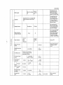
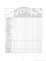
MAJOR DATA AND SPECIFICATIONS
5
DISASSEMBLY
8
INSPECTION AND REPAIR
..........................................
16
REASSEMBLY
37
LUBRICATING SYSTEM
49
COOLING SYSTEM
52
FUEL SYSTEM
56
ELECTRICAL SYSTEM
..............................................
71
BENCH TEST
87
MAINTENANCE STANDARDS
89
SEALANT APPLICATION DATA
102
TIGHTENING TORQUE
103
.............................................
SPECIAL SERVICE TOOLS
105
TROUBLESHOOTING CHART
110
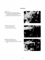
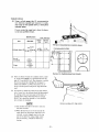
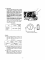
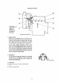
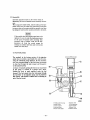
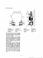
GENERAL
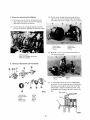
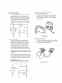
1. Major component parts
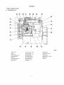
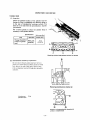
1-1 Left-hand side view
402500
1-Water pump
2-Fan
3-Fan belt
4-Fuel injection pump
5-Fuel feed pump
6-0il pipe
7-Fuel inlet connector
8-Fuel feed pipe
9-Fuel filter
10-Fuel injection nozzle
11-0il filler cap
12-Fuel injection pipe
13.Rocker cover
14-lntake manifold
15-Fuel leak-off pipe
16-Cylinder head
17-Adjusting lever
18-Hanger
-1-
19-Cran kcase
20-Flywheel housing
21-0il pan
22-Drain plug
23-Control rack stopper
24-Governor
25-Starter
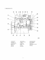
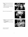
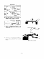
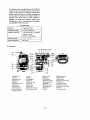
1-2 Right-hand side view
402501
l-Cylinder head
2-Crankcase
3-1 ndicator switch
4-Flywheel housing
5-Rocker cover
6-0il filter
7-Breather
8-0il filler
9-0il filler cap
10-Exhaust manifold
ll-Elbow
l2-Screw plug
13-Water pump
14-Fan
l5-Fan belt
16-Alternator
-2-
l7-Alternator bracket
18-Timing gear case
19-0il level gauge
20-0il pipe
21-0il bypass alarm switch
22-0il pan
23-0il pipe
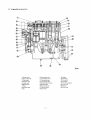
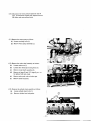
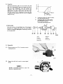
1-3 Longitudinal sectional view
402502
1-Rocker cover
2-Thermostat case
3-Thermostat
4-Exhaust valve
5-lntake valve
6-Water pump
7-Piston
8-Camshaft gear
9-Fan
10-Connecting rod
11-Cran kshaft pu lIey
12-Crankshaft gear
13-Timing gear case
14-Rocker shaft bracket
15-Rocker shaft
16-Valve push rod
17-Cylinder head
18-Cran kcase
-3-
19-Tappet
20-Camshaft
21-Crankshaft
22-Flywheel
23-Flywheel housing
24-0il strainer
25-0il pan
26-Drain plug
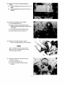
1-4 Transverse sectional view
402503
1-Exhaust manifold
2-Piston
3-Valve push rod
4-Connecting rod
5-Tappet
6-Camshaft
7-0il level gauge
8-0il pump
9-0il strainer
10-Rocker arm
11-Rocker cover
12-Glow plug
13-Fuel injection nozzle
14-lntake manifold
15-Fuel injection pipe
16-Cylinder head
17 -Cran kcase
18-Fuel injection pump
19-Fuel feed pump
20-Starter
21-Cra n kshaft
22-0il pan
-4-
-------~------
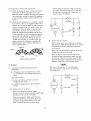
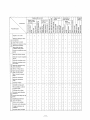
MAJOR DATA AND SPECIFICATIONS
Engine model
40Q5
Water-cooled, 4-stroke, swirl-combustion
chamber type diesel
Type
No. of cylinders-arrangement
4-in line
Bore x stroke
mm (in.)
84 x 94 (3.307 x 3.701)
Piston displacement
cc(cuin.)
2084 (127.l)
Compression ratio
21 : 1
kg/ cm 2 (p si)
Compression pressure
1-3-4-2
Firing order
Direction of rotation
Counterclockwise as viewed from flywheel side
Burns (fuel)
Grade No. 2D diesel fuel (ASTM specification)
Engine oil
Class-CC or better (API service classification)
Overall length
.
ca
26 (369.7), min (at 150 ~ 200 rpm)
Dimensions
Overall width
717.5 (28-1/4)
mm (in.)
562 (22-1/8)
a.I
=
Overall height
a.I
629.5 (24-3/4)
(.!)
Weight, dry
200 (441)
kg (lb)
Dry type made of special cast iron
or integral water-jacket type
Cylinder sleeves
No. of piston
rings
Compression rings
2
1 (w/spring expander)
Oil ring
Overhead
Valve arrangement
Intake valves
Valve
timing
Exhaust valves
Open at:
30° BTDC
Close at:
50° ABDC
Open at:
74° BBDC
Close at:
30° ATDC
Valve clearance (both intake and
exhaust valves) (cold)
0.25 (0.0098)
mm (in.)
Electric
Starter
Fuel feed pump
ND-EP/KS22A
Model
Cam lift
6 (0.24)
mm (in.)
PES4A65B
Model
5
"til
Fuel injection
pump
~
Plunger diam
Governor
Fuel injection
nozzles
Right
Plunger lead
Cam lift
a:i
::I
r-
6.5 (0.256)
mm (in.)
8 (0.31)
mm (in.)
Model
RUV (for prime power)
Type
Centrifugal flyweight, all-speed
Throttle
Type
Bosch CA 17SD
Type of nozzle holders
-5-
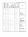
Engine model
4DQ5
Type of nozzle tips
~
~
~
Fuel injection
nozzles
'1:l
""-=
Spray hole diam
Bosch ND-DNOSD21
mm (in.)
0°
Spray angle
Injection pressure
kg/cm 2 (psi)
Fuel filter
e
III
>.
'"
'"
=
.sa
Oil pressure
6)
Trochoid
Speed ratio to crankshaft
~
120 +18 (1706 + 14
Paper-element type
Type
Oil pump
1 (0.04)
1/2
Capacity at oil temp.
50 ± 5°C (122 ± 9°F); liter (cu in.)/
pressure 3 kg/cm 2
min/rpm
(42.7 psi)
At duty run
At idling
kg/cm 2 (psi)
Oil filter
8.37 (510.8), min/lOOO (pump rpm)
3 - 4 (42.7 - 56.9)
1 - 2 (14.2 - 28.4)
Paper-element type
~
.'"
Type
.~
3
Relief valve
Refill capacity
Oil bypass
valve
Piston-valve
Valve opening
pressure
kg/ cm 2 (psi)
Oil pan
liter
(U.s. gal)
Oil filter
Type
Valve opening
pressure
kg/ cm 2 (psi)
e
Thermostat
III
liter (cu in.)/
min/rpm
Valve lift temperature
.Sf
Type
'"
'0
0
U
Fan
76.5 ± 2°C (169.7 ± 3.6°F)
90 ± 2°C (194 ± 3.6°p)
Circular-arc pusher type
No. of blades
Outside diameter
6
mm (in.)
Ratio to crankshaft speed
Drive belt
380 (15)
1.3
Type
Low-edge cog B
No. of belts
Refill capacity (engine water jacket)
105 (6408)/3900 (pump rpm)
Wax
Valve opening temperature
>.
'"
0.8 - 1.2 (11.4 - 17.1)
1.3
Type
~
0.7 (0.18)
Centrifugal type
Speed ratio to crankshaft
Capacity
6.5 (1. 7)
Piston-valve
Type
Water pump
3 ± 0.2 (42.7 ± 2.8)
1
liter
(U.S. gal)
-6-
4.5 (1.2)
Engine model
4DQ5
Working voltage
volt
12
Negative (-) ground
Polarity
Type
Glow plugs
Sheathed
Rated voltage current
volt ampere
Resistance at normal
temperature
ohm
10.5 - 8.3
1.26
M002T54172
Model
=
cv
S
.9-
i
Totally enclosed, drip-proof, pinion-shift type
with overrunning clutch
Type
....
Manufacturer
Starter
Voltage-output
co
.l:t
.......
Mi tsu b ishi-Electric
volt kilowatt
No. of pinion teeth/
No. of ring gear teeth
<:J
~
11/121
Model
A001T25070
Type
3-phase AC type
Voltage-ou tpu t
Alternator
volt ampere
12 - 35
Manufacturer
Rated speed
Working speed
Mitsubishi-Electric
5000
rpm
1000 ~ 13500
Speed ratio to crankshaft
Regulator
12 - 2
1.68
IC type built in alternator
Type
Regulated voltage
14.4 ± 0.3
volt
-7-
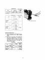
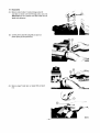
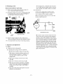
DISASSEMBLY
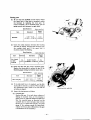
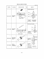
(1) Drain the oil.
(2) Remove the fan belt and alternator as follows:
(a) Loosen bolt (1) securing fan belt adjusting plate
and alternator, and remove fan belt (2).
(b) Remove bolts (1) and (3) and remove alternator.
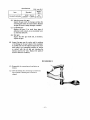
(3) Remove the starter as follows:
(a) Loosen attaching nuts (1).
(b) Remove starter from rear plate.
(4) Remove the fuel filter as follows:
(a) Disconnect fuel feed pipes (1) (2).
(b) Loosen attaching bolts (3) and remove fuel filter
(4).
-8-
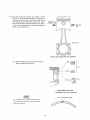
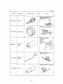
(5) Remove the injection pipes and injection nozzles as
follows:
(a) Loosen connectors (1) and disconnect injection
pipes (2).
(b) Remove fuel return pipe (3) by loosening union
nut.
(c) Loosen nuts (4) and remove fuel leak-off pipe (5).
(d) Remove nozzle assemblies.
(6) Remove the lube oil pipe from injection pump.
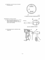
(7) Remove the water pump pulley and crankshaft pulley
as follows:
(a) Loosen water pump shaft nut (1) and remove
water pump pulley (2).
(b) Loosen crankshaft nut (3) and remove crankshaft
pulley (4).
(8) Remove the timing gear case.
(9) Remove the rocker cover.
-9-
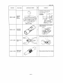
(10) Disconnect the water pump bypass hose and oil
pipe. To disconnect bypass hose, displace thermostat elbow and water pump clamp.
(I 1) Remove the water pump as follows:
(a) Loosen attaching bolts (1).
(b) Remove water pump assembly (2).
(12) Remove the rocker shaft assembly as follows:
(a) Loosen union nut (1).
(b)
Loosen short bolts (2) and long bolts (3).
(c)
Remove rocker shaft assembly (4).
(d)
Remove oil pipe (5) and "0" rings (2 pcs - to
be replaced with new ones).
(e)
Remove valve push rods and valve caps.
(f)
Remove intake manifold.
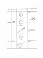
(13) Remove the cylinder head assembly as follows:
(a) Loosen cylinder head bolts (1).
(b)
Remove cylinder head and gasket.
-10-
(14) Remove the oil pan and oil pump assembly as
follows:
(a) Loosen attaching bolts and remove oil pan (1) and
gasket.
(b)
Loosen attaching bolts and remove oil pump (2)
assembly.
(15) Remove the timing gear train as follows:
(a) Loosen idler gear bolt (1).
(b) Remove thrust plate (2) and idler gear (3).
(Draw idler gear while twisting it in the direction
of its helix.)
(c) Loosen injection pump drive gear nut (4).
(d) Remove injection pump drive gear (5).
(16) Remove the camshaft assembly as follows:
Take out camshaft assembly (1) from crankcase.
[NOTE]
There are tappets in crankcase; this makes it
!}ecessary to turn crankcase upside down when
removing camshaft assembly.
(17) Remove the front plate and injection pump
assembly as follows:
(a) Loosen attaching bolts (1).
•
(b) Remove front plate and injection pump
assembly.
-11-
.
. .. ~
...... .. ,
@l
(18) Remove the flywheel and rear plate.
(19) Remove the connecting rod bearing caps and
bearings (lower shells) by loosening attaching bolts.
(20) Remove the connecting rods and pistons.
(21) Remove the main bearing caps by loosening
attaching bolts.
-12 -
(22) Remove the crankshaft.
(23) Remove the main bearing shells.
(24) Disassemble piston and connecting rod as follows:
(a) Remove compression rings (1) and oil ring (2)
by using piston ring tool (A).
(b) Remove oil ring spring.
(c) Remove snap rings (3) by using snap ring tool
(B).
-13-
(d) Remove piston pin (4) by using drift (C).
(e) Remove piston pin bushing and connecting rod
bearing (upper).
(25) Disassemble the rocker shaft assembly as follQws:
(a) Remove snap rings on both ends (1).
(b) Remove rocker assembly (2).
(c) Remove rocker bracket (3).
(d) Remove rocker assembly (4).
(e) Remove spring (5).
(26) Disassembly the cylinder head as follows:
(a) Remove nozzle holders.
(b) Remove glow plugs (l).
(c) Loosen bolts (2) securing exhaust and intake
manifolds.
(d) Remove exhaust manifold (3).
(e) Loosen thermostat cover bolts and remove
thermostat cover (4).
(f) Remove thermostat (5).
-14-
(g) Remove valve cotters (6).
(Depress valve spring by valve lifter.)
(h) Remove retainer (7).
(i) Remove valve spring (8).
G) Take out valve (9).
(k) Remove valve guide by using valve guide
remover (A).
lO-Valve guide
ll-Cy Ii nder head
-15 -
A-Valve guide remover
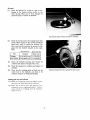
INSPECTION AND REPAIR
Cylinder head
(1) Inspection
Check the gasketed surface of the cylinder head for
flatness by using a straightedge and thickness gauge as
in the case of checking the crankcase surfaces. This
check is to be made with the precombustion chamber
jets removed.
Use a surface grinder to reface the cylinder head, as
necessary, to the specified flatness.
Specifications
Item
Warpage of gasketed
surface of cylinder
head
Unit: mm (in.)
Standard
O.OS,max
(0.0020)
Repair limit
0.20
(0.0079)
B-
L...::t=---.....o--_.... . .
~ ·F
I
Checking cylinder head gasketed surface for flatness
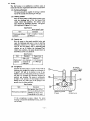
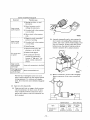
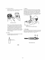
(2) Precombustion chamber jet replacement
Do not remove the jets unless they have to be replaced. To remove the jet as when cracks are noted
in it, drive it out with a drift pin of about 6 mm
0/4 in.) diameter inserted through glow plug hole,
as shown.
Removing precombustion chamber jet
A·lntake port
B-Exhaust port
©
C·Jet
Direction of precombustion chamber jet
orifice in installed state
-16 -
Valve guides and valve seats
(1) Check each valve for carboning, burning, wear or
other defect on head; also check cap end and stem
for cracks. Replace the valve if damaged.
(2) Check each valve guide for wear. Remember, the
guide wears down more rapidly at its both ends
than at any other parts. Measure the inside diameter of the guide at its ends and a t its middle
part in two directions. Measure the outside diameter of each valve stem. If the measurement
exceeds the repair limit in Table below, replace
the valve guide.
(
,,
,,
)
.
:~
~:
Wear on valve guide
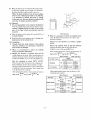
Specifications
(3) Valve face and valve seat
Check valve face and valve seat for wear and
contact. If valve face is found excessively worn,
reface it by using a valve refacer. To reface the
valve, proceed as follows:
Repair
limit
Standard
Item
Clearance
of valve
stem in
valve guide
Unit: mm (in.)
Intake
0.15
0.055 -0.OS5
(0.00217 -0.00335) (0.0059)
0.20
0.070-0.105
Exhaust (0.00276-0.00413) (0.0079)
Valve guide
length outside hole
18 ± 0.3
(0.709 ± 0.012)
S -0.045
-0.10
(-0.0039)
-0.060
Intake
(0315 -0.00177)
.
Valve stem
diameter
-0.00236
8 -0.060
Exhaust
(0315 -0.00236)
.
-0.00315
Specifications
Item
Angle
Valve
seat
Nominal
value
Standard
Unit: mm (in.)
Repair
limit
Service limit
30°
Sinkage
O.S (0.031)
±0.2
(±O.OOS)
(0.051)
Width
1.4 (0.055)
±0.14
(±0.005S)
1.6
(0.063)
1.2
(0.047)
1.7 (0.067)
-17 -
~
1.3
Reface up to
Valve margin
-0.15
(-0.0059)
-0.080
n
~~~ ~I~am
C:J~
Valve seat
angle
~
Face
~ tValve sinkage
l
i
1
Counterbore Valve margin
Valve refacer
(a) Set a valve refacer to an angle of 45 degrees.
(b) Grind the valve stock to a minimum and, if the
margin is less than 1.2 mm (0.047 in.), replace
the valve.
Valve seat cutter
Repair an excessively worn valve seat by using a
valve seat grinder or valve seat cutter.
(c) When using a valve seat cutter, exercise care so
as to apply a uniform pressure to valve seat to
prevent uneven cutting. After cutting, reface
the seat by rotating the cutter with No. 400
sandpaper put between the cutter and seat.
(d) If valve seat width is overcut, repair it using a
30-degree cutter. If valve seat width exceeds
1.6 mm (0.063 in.) due to wear, rep.lace the
seat. Also replace the seat when valve sinkage
exceeds 1.3 mm (0.051 in.).
Valve seat installation
Chill the valve seat inserts in ether or alcohol containing
dry ice. Heat the cylinder head to a temperature of 80°C
to 100°C (176°p to 212°p). Press the inserts in the
cylinder head by using the insert calking tools (3069102700 for intake valve, 30691-02800 for exhaust valve).
Leave the cylinder head and the inserts in the air until
shrinkage-expansion fit is obtained between the two.
Calk around the inserts with the insert calking tool to
machine the seat width.
(NOTE]
The insert calking tool may be used both for
pressing and calking the valve seat inserts by
reversing the calking ring.
-18 -
'Valve springs
Inspect each spring for cracks, and check it for squareness, free length and as-installed length against these
specifications:
Specifications
Unit: mm (in.)
Item
Standard
Repair
limit
Valve spring free length
48.85
(·1.9232)
47.6
(1.874)
Valve spring squareness
1.5°, max
Load compress spring to
initial working lenfth
[43 mm (1.69 in.)
kg(lb)
19 ± 1
(41.9 ± 2.21)
15
(33.08)
Checking valve spring
Checking valve spring for squareness
Exhaust manifold
If the flange faces are warped by more than 0.2 mm
(0.0079 in.) when checke<;l as shown, grind them smooth
and flat. If any flange is found cracked, replace the
manifold_
Checking exhaust manifold flange surface for flatness
-19 -
Cylinder sleeves
(1) Using a cylinder gauge, take ID measurements in
two directions (parallel and transverse to crankshaft axis) on each cylinder sleeve, at three places
indicated below.
If wear reaches the repair limit, reb ore the sleeve
to the next specifted oversize.
Specifications
Item
Standard
Unit: mm (in.)
Repair
limit
Service
limit
I
Taking ID measurements on cylinder sleeves
84 +0.035
Crlnkcase gaske,ed surfKe
0
+0.20
0.70
Cylinder sleeve ID (3.307 +g.00138) (+0.008) (0.0276)
oJ,
0111
Out of
roundness
Taper
0.1
(0.004),
max
0.015
(0.0006),
max
~~'
r
(0.43i
1
.:)
2
3
'.
Positions for checking sleeve bore diameter
(2) There are three oversizes for cylinder sleeves, namely, +0.25 mm (0.0098 in.), +0.50 mm (0.0197 in.)
and +0.75 mm (0.0295 in.). The tolerance to which
the sleeves should be refinished by boring is 0 0.035 mm (0.0014 in.). When the sleeves are rebored, oversize pistons and piston rings should be
used.
(3) An oversize to which any sleeve worn taper and/or
out of round is to be rebored should be determined
by relying on the most worn part of the sleeve. A
cylinder sleeve whose abnormal wear is 0.4 mm
(0.0157 in.) should be rebored to 1 mm (0.0394
in.) oversize, for example.
(NOTE]
Removing ridge with ridge reamer
a) All cylinders should be rebored to one and
the same oversize.
b) When the sleeves are not worn beyond the
repair limit, but the piston rings have to be
renewed, correct stepped wear on the top
part of the sleeve by using a ridge reamer
and, if necessary, refinish the sleeves by
honing.
-20 -
(4) When the sleeves are worn beyond the service limit,
or when any cylinder bore is found to be defective,
the sleeve should be replaced with a new one.
When the inside surfaces of one of more cylinder
bores in the crankcase are found to be defective,
it is necessary to refinish the bores by boring.
In this case, too, the liners should be replaced with
new ones. To replace, proceed as follows:
(a) Removal
e Fix a boring machine to the crankcase in alignment
with the cylinder bore from which a sleeve is to be
removed. Aligning should be made at the bottom
part of the liner where less abnormal wear has
occurred.
•
Bore the sleeve until it reaches 0.5 mm (0.0197 in.)
in stock thickness.
•
Break the sleeve, exercising care not to damage the
inside surface of the cylinder bore.
Pressing sleeve
• When it is necessary to rebore the cylinder bores,
press the sleeves into position as in b above, and
proceed as follows:
Prepare 0.5 mm (0.0197 in.) oversize cylinder
sleeves.
(b) Installation
It Visually check the inside surfaces of the cylinder
bores for condition. It is necessary to rebore the
bores if they are damaged.
Rebore the cylinder bores so that the clearance
between the sleeve and the bore is 0.08 mm
(0.0031 in.) to 0.145 mm (0.0057 in.).
e When it is unnecessary to reb ore the cylinder
bores, proceed as in steps below.
• Measure. the diameter of cylinder bore and the
outside diameter of sleeve. Select oversize sleeve so
that the clearance between the sleeve and the bore
is 0.08 mm (0.0031 in.) to 0.145 mm (0.0057 in.).
After pressing the sleeves, rebore and hone them to
them t a 84 +0.035
(3307 +0.0014.
)
0
mm.
0
m ..
Cylinder sleeve
Heat the crankcase to about 300°C (572°F).
Press the sleeve into the bores in the crankcase by
using a hydraulic press in such a manner to make
the top of sleeve protrude by 0.3 to 0.5 mm (0.012
to 0.020 in.) from the crankcase. Then, finish them
to be flush with the crankcase.
After pressing the sleeves, rebore and hone them to
Specifications
Unit· mm (in )
Sleeve
boring dimension
Standard
87 -0.010 (3 425 -0.0004)
-0.045 .
-0.0018
0.5 -oversize
875-0 .010 (3 445 -0.0004)
. -0.045 .
-0.0018
When replacing the sleeves, use the sleeves of the
following part numbers.
them t a 84 +0.035
(3307 +0.0014.
)
0
mm.
0
tn ..
Unit: mm (in.)
Specifications
Part No.
0.0.
1.0.
Remarks
0
87+0 .10
83.5
+0.07
-0.2
Standard
30607-50301
(3 425 +0.0004) (3.287_0 .
)
.
+0.0028
0 008
0
875+0 .10
83.5
. +0.07
-0.2
30607-50401
Oversize
0
(3445 +0.0004)
.
+0.0028 (3.287 -0.008)
-21-
Pistons and piston rings
(1) Pistons
Inspect each piston for any abnormal wear of its
sliding surface, for cracks at the crown and for
evidence of melting or fusion. Examine the ring
grooves for stepped wear and sloped wear. Replace
pistons found in bad condition.
(2) Measure the outside diameter of piston in two directions perpendicular to each other. If the diameter
exceeds the service limit, replace the piston.
Specifications
Item
Diameter
(at skirt)
Standard
Unit: mm (in.)
Service
limit
Standard
83.90 (3.3031)
0.25 (0.0098)
oversize
84.15 (3.3130)
0.50 (0.0197)
oversize
84.40 (3.3228)
0.75 (0.0295)
oversize
84.65 (3.3327)
-0.2
(-0.008)
-22-
Front of engine
(3) Replacing pistons
Replace the piston with a new one if the measurement exceeds the service limit. Where any pistons
have to be replaced, the variance in weight among
the pistons must not exceed the limit. It is
recommended that cylinder number be stamped
on a piston selected to be used in a particular cylinder for convenience.
When the cylinder sleeves are bored to the oversize,
pistons and piston rings of the same oversize
should be used. There are three oversizes for pistons
and piston rings, namely, +0.25 mm (0.00984 in.),
+0.50 mm (0.01969 in.) and 0.75 mm (0.0295 in.).
The variance in weight among the pistons per engine
should be ±5 grams (±0.18 oz), max.
t
Pilton _ight
Piston weight marking
(4) Piston riD& gaps
Check the ring gap with a thickness gauge by
placing the ring in a new cylinder sleeve, and
pushing the pistOll true and square in the bore.
Piston ring
Gap
Checking piston ring gap
Specifications
Item
Unit: mm (in.)
Service
limit
Standard
0.30 ~0.50
(0.0118 ~ 0.0197)
Piston ring gap
1.5
(0.059)
(5) Piston ring grooves
Insert the compreuion and oil rings of known
thicknesses into the grooves, and measure the
side clearance with a straightedge and thickness
gauge@.
Measuring piston ring groove
Specifications
Item
No.1 compression
Fit in ring ring
grooves
No.2 compression ring
Oil ring
Standard
Unit· mm (in )
Repair
limit
0.050 ~ 0.085
(0.00197 ~ 0.00335
0.20
(0.0079)
0.025 ~ 0.060
(0.00098 ~ 0.00236)
0.15
(0.0059)
-23 -
(6) Replacing piston riDp
If the rings are replaced, the gap width will exceed
the standard value, but this is not a matter of
concern, provided that the service limit is not
exceeded.
(7) Piston pin bosses
Check the piston pin bosses by referring to the
topic, Piston pins, piston pin bosses and piston
pin bushings, which follows.
Piston pins, piston pin bosses and piston pin
bushings
(1) Check the pin clearance in the pin boss of the
piston by computing the difference between the
two diameter readings, one taken on the pin and
the other in the boss. If the computed difference
(clearance) exceeds the repair limit, replace the
piston pin with a new one.
Specifications
Item
Unit: mm (in)
Standard
Repair
limit
Miking piston pin bushing and piston pin
0
25 -0.006
Piston pin
diameter
(0.984_8.00024 )
(2) ('heck the clearance of the pin in the bushing
fitted to the small end of the connecting rod by
computing the difference between the two dia·
meter readings.
If the computed difference
(clearance) exceeds the repair limit, replace the pin
or the bushing whichever is badly worn.
Specifications
Item
Piston pin boss
ID
Unit· mm (in )
Repair
Standard
limit
25 -8.006
(0.984 -8.00024)
Piston pin clearance in piston
pin boss
Piston pin
bushingID
Piston pin clearance
in piston pin bushing
0-0.016
(0 - 0.00063)
0.05
(0.0020)
25 +0.020
·+0.045
+0.00079
(0.984 +0.00177 )
0.020 - 0.051
(0.00079 0.00201)
0.08
(0.0031)
-24-
Connecting rod alignment and bearings
(l) Check the connecting rod for evidence of cracks,
especially cracks in the fillets of its small and big
ends. Replace the rod if any cral:k is noted in the
fillets.
f
t
(2) Mount each connecting rod in the connecting rod
aligner and check for bend and twist as shown
below. In a twisted connecting rod, the bearing
is not trued to the small end bushing. Such a rod
must be corrected with the use of a press.
<0.05
100
a. Checking the connect·
ing rod for bend
(3) If the connecting rod aligner is not available, the
rod may be checked as follows:
b. Checking the connect·
ing rod for twist
Checking connecting rod
(a) To check the rod for bend, measure "c" and
"2" as shown in the figur~ "a." If the measurement at "c" is larger than 0.05 mm per 100 mm
(0.00197 in. per 3.937 in.) of" 2," straighten
the rod with the use of a press.
Checking connecting rod for bend
(b) To check the rod for twist, measure "c" as
shown in the figure "b." If the measurement at
"C" is larger than 0.05 mm per 100 mm
(0.00197 in. per 3.937 in.) of "2," correct the
rod.
Checking connecting rod for twist
-25 -
(4) To ~he.:k the rod with a piston, pla~e the rod on
the surfa~e plate as shown below, insert a
round bar of the ~rankpin diameter into and
through its big end bore, and take measurement
at "A" and "B." The differen.:e between the two
measurements tel1s the straighteness of the rod.
When one or more, or all connecting rods are to
be repla~ed, sele~t new rods so that the variance
in weight among the rods is within the value
given in the spedfication.
Specification
Unit: gram (oz)
B
A
Variance in weight
among connecting rods
//
/
Checking connecting rod on surface plate
(5) Check the connecting rod end playas follows:
Check each connecting rod for end play in the
manner illustrated, with the cap bolts tightened
to 5.5 kg-m (39.8 lb-ft). Use a thickness gauge to
measure the end play (which is the clearance between
big end and crank arm). If the clearance measured
exceeds the service limit, replace the connecting
rod or bearing.
Specifications
Unit: mm (in.)
Item
Standard
Service
limit
Connecting rod
end play
0.15 -- 0.35
(0.0059"" 0.0138)
0.50
(0.0197)
Checking end play of connecting rod
(6) Check the bearings as follows:
(a) Inspect each bearing for evidence of wiping or
fatigue failure, for scratches by dirt particles
imbedded in and for improper seating on the
bore. Determine whether the bearing should
be re-used or replaced on the basis of fmdings.
(b) Check the radial clearance between crankpin
and bearing; if the repair limit speCified below
is exceeded by the checked clearance, replace
the bearing. Where the crankpin is to be ground
to the next undersize, use a replacement bearing of that undersize.
The two bearing undersizes are 0.25 mm
(0.00984 in.) and 0.50 mm (0.01969 in.).
-26-
Specifications
Item
Standard
Crankpin diameter
58 -0.035
-0.055
(2283 -0.00138)
.
-0.00217
Radial clearance
between bearing
and crankpin
Unit: mm (in.)
0.035 ...., 0.100
(0.00138"'" 0.00394)
Repair
limit
0.20
(0.0079)
To measure the inside diameter of the bearing,
the bearing fitted to each connecting rod must
be secured by tightening the cap bolts to
5.5 kg·m (39.8 lb·ft). Measure the diameter in two
positions, 1 and 2, and in two directions D\ and D2,
as shown below. Obtain the average by the follow·
ing formula:
01 + 02
0---2
....
r.1:":<:':"'~
2
1
Positions for miking connecting rod bearing
(c) Check the contact pattern of bearing on
crankpin by fitting the big end in the normal
manner to the crankpin, with the crankshaft
laid out on the bench, and by using a paste of
red lead or Prussian blue to visualize the contact. Be sure to tighten the cap bolts to the
specified torque, that is,5.5 kg·m (39.8 lb·ft). The
contact should occur over at least 75% of the
entire surface; if not, replace the bearing.
[NOTE]
The above job of checking the contact pattern
may be eliminated where the crankpin is ground
to the specified tolerance and the bearing has
been replaced. This is because a replacement
bearing is precision·finished to ensure the speci·
fied extent of contact.
Miking connecting rod bearing
-27 -
Crankcase
(1) Inspect the outside and inside surfaces for evidence
of cracking. VisuaUy examine the cylinder bores
for scuffing, rusting, erosion or any abnormal
wear. Using a straightedge, check the top face
(for mating with cylinder head), front face (for
mating with front plate) and rear face (for mating
with rear plate) for flatness.
(2) Make sure that the top face of the crankcase is
flat within the standard specified below. If the
standard is found to be exceeded, reface the top
by using a surface grinder to make it flat within
the specified standard.
Specifications
Unit: mm (in.)
Item
Warpage of crankcase
gasketed surface
Standard
0.05, max.
(0.0020)
Repair
limit
0.20
(0.0079)
Checking crankcase top for flatness
Crankshaft
(1) Journals
(a) Inspect each journal for surface flaws such as
roughing, scratches, pitting and bums, and, as
necessary, repair the journals by grinding to the
next undersize or replace the crankshaft.
(b) Mike each journal to take a total of four readings to determine the wear, out-of-round and
taper (cylindricity). If any of the limits is
exceeded, repair by grinding to the next undersize or replace the crankshaft.
Positions for miking journal
-28-
(l) Crankpins
(a) Inspect each crankpin for surface flaws such as
roughing, scratches, pitting and bums, and, as
necessary, repair the crankpins by grinding to
the next undersize or replace the crankshaft.
(b) Mike each crankpin to take a total of four
readings to determine the wear, out-of·round
and taper. If any of the limits is exceeded,
repair by grinding to the next undersize or
replace the crankshaft.
Miking crankshaft crankpins
Specifications
Item
Diameter of
journals
Standard
Repair
limit
Service
limit
65-0.015
-O.oJ5
-0.15
-0.9
(2 559-0.00059 (-0.0059) (-0.035)
. .-0.00138
Out of round·
ness of crank·
pins and journals om (0.0004),
max
Taper of crank·
pins and journals
Diameter of
crankpins
Unit: mm (in.)
0.03
(0.0012)
•
58-0.oJ5
-0.055
-0.20
(228rO.00138) (-0.008)
. -0.00217
0.03 -0.089
Fit of journals
(0.0012
in main bearings
0.00350)
0.2
(0.0079)
Uneven
wear:
0.03
(0.0012)
-29-
(c) Grinding the crankshaft
The crankshaft journals and crankpins must be
refinished to a dimension smaller by 0.100 to
0.120 mm (0.00394 to 0.00472 in.) than the
undersize of bearings to be used.
Example:
If 0.50-mm (0.01969-in.) undersize
bearings are to be used:
The journals must be refinished to
65 - 0.5 - (0.100 - 0.120)
[2.55905 - 0.01969 - (0.003940.00472 in.)]
The crankpins must be refinished to
58 - 0.5 - (0.100 - 0.120)
[2.28346 - 0.01969 - (0.003940.00472 in.)]
When grinding the crankpins and journals, be
sure to produce the same filler radius (shoulder
radiUS) as the original one. Too small a radius of
fillet will result in fatigue failure of crankshaft
while too large a fillet radius is sure to cause the
bearing to ride on the radius and thereby to
result in a bearing failure. Be extremely careful
not to grind off the radius part beyond the
desired dimension. An over-ground radius part
can be corrected only by grinding off the
shoulder face and this, if effected, will present
problems in obtaining a proper end clearance.
Also check the crankpins and journals for hardness. They should have a hardness of 620 or
more in terms of Vickers Hardness Number. If
necessary, re-harden the crankpins and journals,
and check them for cracks by conducting a
magnaflux (magnetic particle) test.
Specifications
Unit: mm (in.)
Journals to be refinished to
Undersize
0.25
(0.0098)
!. 64 .75 -0.015
(25 92 -0.00059)
-0.035 . 4 1-0.00138
0.50
(0.0197)
6450- 0.015 (2 5393To.00059)
. -0.035'
-0.00138
0.75
(0.0295)
6425 -0.015 (2 52952 -0.00059 )
.
-0.035'
-0.00138
-30-
(3) End play
Check the crankshaft for end play, as shown, by
using a thickness gauge at the thrust bearing. If
the limit is reached replace the thrust plate.
Specifications
'\,
Unit: mm (in.)
'"
Item
Standard
'----
Journal width
for thrust
bearing
Repair
limit
0.100-0.189
0.3
(0.00394 - 0.00744) (0.012)
:2/
;7/
/
The end play is due to the difference between the
width of thrust bearing and the dimension (A)
indicated below:
Checking crankshaft end play
o
A
Journal width for thrust bearing
(4) Runout
Support the crankshaft as shown and roU it to
measure its deflection with a dial gauge. "Distortion" is one·half of the deflection (dial gauge
reading); if it exceeds the standard, reduce it by
bending the crankshaft in a press.
Specifications
Item
Crankshaft runout
Unit: mm (in.)
Standard
Repair
limit
0.02
(0.0008), max
0.05
(0.0020)
Checking crankshaft for runout
- 31-
J8800
(5) Main bearings
Inspect each main bearing for evidence of wiping
or fatigue failure, for scratches by dirt particles
imbedded and for improper seating on the bore
(bearing cap). On the basis of fmdings, determine
whether the bearing should be replaced or not.
Check each main bearing to be used in engine
reassembly to see whether it will provide the specified radial clearance. This can be accomplished in
this manner.
Install the main bearinp on the crankcase, less the
crankshaft, securing each bearing cap by tightening
its bolts to 8.5 kg·m (61.5 lb-ft) and read the
diameter in the two directions (A) (B), in indicated
below. Mike the journal and, from these readings,
compute the radial clearance.
Specifications
Item
Fit of main
bearings on
journals
Unit: mm (in.)
Standard
0.03
(0.0012
Measuring main bearing 10
~0.089
~0.00350)
Repair
limit
0.200
(0.00787)
Positions for miking main bearing
Camshaft
(1) Check the camshaft end playas outlined for the
timing gears. Where the end play exceeds the
repair limit, replace the thrust plate with a new
one.
Specifications
Unit: mm (in.)
Item
Camshaft end
play
Nominal
value
Standard
0.05 - 0.112
5.0
(0.00197 (0.197)
0.00441)
Repair
limit
0.3
(0.012)
(2) Inspect the camshaft journals for abnormal wear
and damage; the camshaft must be replaced if any
of its three journals is found in bad condition
beyond repair.
(3) Mike each cam of the camshaft to read 01 (cam
height) and lh (diameter), and compute the
difference between 01 and 01. If this difference
is less than the service limit, replace the camshaft.
- 32-
Specifications
Standard
Item
Unit: mm tin.)
Service limit
01: 46.916 ~gJ
Intake
cam
profile
Exhaust
cam
(DI - D1)
W'
D2
profile
01 - O:z =
(1 84108 +0.00394)
.
-0.01181 6.184
(0.24346)
01 - 01 ,. 6.684
(0.26315)
01: 45.944 ~J
01 - O:z =
80882 +0.00394) 6.844
.
-0.01181
(0.26945)
01 - Ol = 1.344
(0.28913)
(1
(4) Check the camshaft for runout. Straighten the
camshaft in a press or replace it, as necessary.
Specifications
Item
Camshaft runout
Unit: mm (in.)
Standard
Repair
limit
0.02 (0.0008),
max.
0.05
(0.0020)
(5) Measure the diameter of each journal in two
directions to compute the fit or clearance in the
camshaft hole.
Checking camshaft runout
(6) Measure the ID of camshaft holes (bushings) and
compute the fit on each journal. If the fit exceeds
the repair limit, machine the holes and install
bushings.
Miking camshaft journals
-33 -
Specifications
Standard
Repair
limit
0.040 -- 0.090
(0.00157 --0.00354)
0.15
(0.0059)
Item
Fit of camshaft
journals in holes
(bushings)
Unit: mm (in.)
Unit: mm (in.)
Specifications
Item
Service
limit
Standard
54H7 +0.030
No.l,2
Camshaft
bushing
inside
diameter
0
(2.126H7 +g.00118)
Miking camshaft hole ID
53H7 +0.030
0
No.3
(2.087H7 +g.00118)
54 -0.040
Camshaft
journal
outside
diameter
No.1,2
-0.060
(2 126 -0.00157)
.
No.3
-0.00236
53 -0.040
-0.060
)
(2.087 -0.00157
-0.00236
-0.1
(-0.004)
Tappets and tappet holes
(1) Inspect the riding face of each tappet for wear,
contact pattern and crack. Replace defective
tappets.
(2) Check the fit of the tappet in the hole against the
repair limit, indicated below. If the limit is
exceeded, then replace the tappet. If the hole is
worn down so much as to provide an excessive
radial clearance even with a new tappet, the
crankcase must be replaced.
Specifications
Item
Fit of holes
on tappets
Tappet hole
diameter
Standard
0.035"" 0.098
(0.00138 ...,
0.00386 )
22(0.87)
Repair
limit
Unit: mm (in.'
Service
limit
0.12 +0.10 (hole)
(0.0047) (+0.0039)
+0.10
(+0.0039)
-34-
Flywheel
(1) Check the flywheel for scoring or a sign of overheating of the friction surface, cracks, or any
other damage. When any of these damages are
presented, repair or replace the flywheel.
",:e" I t
J
Ifi
Checking flywheel friction surface for warpage
(2)
Check the friction surface for warpage and/or face
run out. When warpage or face runout exceeds the
repair limit, repair or replace the flywheel. The
face runout may be measured by means of a dial
gauge with the flywheel installed on the crankshaft.
Specifications
Unit: mm (in.)
Item
Warpage
Standard
Repair limit
0.15 (0.0059), max. 0.5 (0.020)
Face runout 0.15(0.0059), max.
0.5 (0.020)
(3)
Check the flywheel attaching bolt threads for
condition and replace a damaged bolt, if any.
(4)
Check the ring gear for condition and replace it if
damaged.
(5)
Clean the pilot bushing which is fitted into the
center bore in the flywheel, and check it for
condition. Replace the bushing if damaged.
Checking flywheel friction surface for face runout
Timing gear case and oil seal
(l) Check the timing gear case for any signs of cracks:
also check the dowel pin holes for condition.
(2) Check the llil seal for wear, and replace it if it is
excessively worn or otherwise defective, Check it
more carefully if oil leakage from the crankshaft
end is excessive,
~
35
~
Timing gears
(1) Be sure that the backlash in each mesh is within
the repair limit. If the limit is exceeded, reduce
the backlash by replacing the worn gear. To
measure backlash, use a thickness gauge: put the
gauge squarely into between two gear teeth.
Specifications
Unit: mm (in.)
Repair
limit
Standard
Item
0.05 ~ 0.20
0.25
(0.0020 ~ 0.0079) (0.0098)
Backlash
(2) Check the radial clearance between idler bU5hing
and shaft by miking. Compute the clearance from
the readings taken and, if the repair limit is
exceeded, replace the bushing.
Specifications
Nominal
Item
Fit of shaft
in idler
bushing
Unit: mm (in.)
Standard
Repair
limit
36
0.025 -0.075
0.1
(1.417) (0.00098 -0.00295) (0.004)
(3) Check the idler end play with a thickness gauge.
Replace the thrust plate to reduce the play if the
thickness gauge reading exceeds the repair limit.
Specifications
Item
Idler end play
Unit: mm (in.)
Standard
0.05
(0.0020
~0.15
~0.0059)
Repair
limit
0.35
(0.0138)
(4) If the idler shaft has to be replaced, use the idler
shaft puller to remove it, as shown. When installing
the replacement shaft, check to be sure that the
oil holes are aligned.
Checking idler end play
(5) Inspect the timing gears as follows:
(a) Camshaft gear
Replace the gear if its teeth show evidence of
flaking or excessive wear, or if its keyway is
galled, worn or otherwise disfigured. Make sure
that the camshaft gear as mounted on the
camshaft has no more end play than 0.4 mm
(0.0157 in.): to check the end play, use a dial
gauge. If the reading exceeds the repair limit,
replace the thrust plate. (Remember, this gear
is shrink-fitted to the camshaft.)
-36 -
Specifications
Item
Camshaft end play
Standard
Unit: mm (in.)
Repair
limit
0.05 - 0.112
0.3
(0.00197 - 0.00441) (0.012)
(b) Injection pump drive gear
Inspect the gear teeth for damage and also the
mounting bolt holes for malcondition. Replace
the gear if found in badly damaged condition.
(c) Crankshaft gear
Replace the gear if its teeth show signs of
defective tooth contact, or are excessively worn
or otherwise defective.
(d) Idler gear
Inspect the idler gear teeth and, as necessary,
replace the gear.
(6) Inspect the gear case for cracks, and for evidence
of oil leakage at the part ahead of the crankshaft.
A cracked case must be replaced. Inspect the crankshaft pulley, too, examining condition of surface
in contact with the oil seal and checking the
keyway and key for wear. Replace the pulley if
found in defective condition.
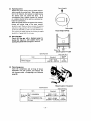
REASSEMBLY
(1) Reassemble the connecting rod and piston as
follows:
(a) Drive in bushing into connecting rod small end.
The oil holes in bushing and rod must be
aligned.
- 37-
(b) Heat piston with piston heater up to loooe to 1200 e
(212° F to 248°F). Install small end of connecting rod
into boss and connect piston and piston pin by slowly
inserting piston pin into piston. Insert snap ring in
one end in advance. Install connecting rod to piston
so that the marking side of the connecting rod big end
comes to the camshaft side.
...
Combustion
chamber side
@
Camshaft
side
Marking side
PISTON AND CONNECTING ROD ASSEMBLY
(c) Install compression rings and oil control ring as
shown by using piston ring tool.
PISTON RINGS INSTALLED
1-Compression rings 2-0il control rint
(NOTE )
This mark comes on top side.
No.2 ring has "R" or "RN" mark on its top
side. Be sure that this side is on top when the
ring is. in the groove.
- 38-
(d) Install No.3 oil control ring (1) and expander
(2) as shown below.
CD
J 8693
OIL CONTROL RING AND EXPANDER INSTALLED
(2) Reassemble the crankcase as follows:
(a) Drive three camshaft bushings (1) into camshaft
holes in crankcase by using adapter (A).
(If the fit exceeds the repair limit, machine the
holes and install bushings.)
Driving in
DRIVING IN CAMSHAFT BUSHING
(b) Drive idler shaft (2) into crankcase by using
installer (B).
·-39 -
(c) Lightly apply engine oil to the crankpins and install main bearings (upper). Securely engage the
bearings with the crankpins.
(3) Install the piston assembly as follows:
No.1 ring gap
Install connecting rod bearing (upper) (1) into
the big end of connecting rod_ Apply engine oil in the
internal surface of bearing and on the external periphery of piston. Position piston rings so that ring gaps
0
lire located 90 in respect with each other as shown,
and then insert piston assembly (2) into crankcase.
Alignment marks on the connecting rod must face the
camshaft side. Put cap attaching bolts (3) into rod in
advance. Insert piston assembly into crankcase by using piston guide (A).
-40-
No.2 ring gap
Precombustion-chamber side
(4) Install the crankshaft as follows:
(a) Install thrust plate (1) and two woodruff keys
(2) to the crankshaft and drive in crankshaft
gear (3) by using installer (A).
(b) Install crankshaft to the crankcase.
(5) Install the main bearing caps as follows:
(a) Apply engine oil to the crankshaft journals and
pms, and install the crankshaft in the crankcase securely. Attach main bearing (lower) (I) to main bearing
cap (2) ( front, center and rear) and install the cap in
place aligning it with dowel pin (A) of crankcase.
(b) Measure the crankshaft end play with a thickness
gauge. Replace No.1 main bearing if the end play is
out of specification. Tighten main bearing cap bolts
(3) to a torque of 8.5 kgm (61.463 Ib.ft).
(6) Install the connecting rod bearing caps as follows:
(a) Install connecting rod bearing (lower) (2) into
cap (I) and apply engine oil to the internal surface of
the bearing, and then install the cap with the matching mark on the cap aligned with the mark (A) on the
rod.
-41-
(b) Tighten connecting rod clamping nuts to a torque of
5.5 kgm (39.771 lb.ft).
(7) Install the retainers and gaskets as follows:
(a) Install retainers (1) to the external peripheries
of main bearing caps No.1 and No.3 with the
flange facing the case inside.
(b) Apply ThreeBond 1102 (adhesive) on both sides
of oil pan gasket (2) and attach it to crankcase.
Make sure that the gasket is completely attached
in the grooves (A) in the caps.
(c) Apply Atomjet on the both ends of rubber
packing (3) and insert the packing into cap.
-42 -
(d) Install sleeve onto the rear end of crankshaft.
Apply clean engine oil to the internal surface of oil
seal (I) and secure it with bolts (2) by using oil seal
aligner,
(e) Apply Atomjet at the tip of bolts (3) as they fit into
four through-bolt holes in the bearing cap. Tighten
the bolts to a torque of 0.4 kgm (2.9 lb.ft).
(8) Install the front plate as follows:
(a) Apply ThreeBond 1102 to the both sides of front
plate packing and attach the packing to the front
face of crankcase. Secure front plate (1) with injection pump installed with two bolts (2). The
tightening torque of the bolts is 2.1 kgm (15.2Ib.ft).
(b) Heat camshaft gear to 150°C to 180°C and fit
it to shaft.
,
1
(c) Slowly insert camshaft into crankcase.
jJ
-43-
--
(d) Tighten camshaft thrust plate to crankcase by using
machining holes in camshaft gear.
(9) Install the idler gear as follows:
(a) Install idler gear by matching the timing mark
on each gear.
Timing gear match marks meeting each other
1-Camshaft gear
2-Cran kshaft gear
3-ldler gear
4-lnjection pump gear
(b) Inspecting valve timing after installation of
timing gears
It is not necessary to check the valve timing,
provided that all matching marks on the timing
gears are aligned. Check the timing for verification
as follows:
Using a 3 mm (0.12 in.) thick smooth steel plate,
add 3 mm (0.12 in.) clearance to intake and exhaust valves of No. 1 cylinder. Then, insert a 0.05
mm (0.0020 in.) thickness gauge into between the
top of valve cap and rocker, and slowly turn the
crankshaft, trying to find a position where the
thickness gauge is firmly gripped (the valve starts
opening) and a position where the gauge is just
ungripped (the valve starts closing). Check to
make sure.that these positions coincide with the
angular positions shown in the valve timing diagram with 3 mm (0.12 in.) clearance added to
the valves.
Direction of rotation
t
Exhaust
BDC
Valve timing diagram
TDC
Direction of rotation
Intake
.......--~f---+t-Exhaust
BDC
Valve timing diagram with 3 mm (0.12 in.)
clearance added to valves
-44-
(10) Install the oil pump assembly as follows:
(a) Install oil pump into the oil pump installation
hole in the crankcase and mesh the pump drive
gear with camshaft pump drive gear.
(b) Tighten bolt and secure the oil pump.
(11 ) Install the oil pan.
(12) Install the rear plate and flywheel as follows:
(a) Drive in dowel pin (1), and secure flywheel (2)
complete with pilot bearing in place with bolts
(4) and lock washers (3).
(b) Bend lock washers properly to lock bolts.
Unit; kg-m (lb-ft)
Flywheel bolt
tightening torque
8.S to.5
(61.5 t 3.6)
(13) Reassemble the cylinder head as follows:
•
(a) Drive valve guide (2) into cylinder head (1) as
shown.
B
1-CYlinder head 2-Valve guide A-Valve guide installer 8-Asinstalled length: 18mm(0.709 inl
-45 -
Install stem seal (3) to the valve guide. Completely fit
the breast of the seal in the guide groove.
(b) Install valve (4), valve spring (5) and retainer (6)
in this order. Compress the spring with a valve lifter
to install valve cotter (7) securely. Install caps (8)
when installing rocker shaft assembly.
(c) Install thermostat, nozzle holders, glow plugs
and exhaust manifold in the cylinder head.
CYLINDER HEAD ASSEMBLY
1-Cvlinder head 2-Valva guide 3-Stem seal 4-Valve
5-Valve spring 6-Retainer 7-Valve cotter a-Valve cap
I-Combustion chamber jet
(14) Install the cylinder head assembly as foJIows:
(a) Place the gasket (1) to crankcase (2) and install
cylinder head (3). Use two guide bolts (4) to
prevent the gasket from moving when placing
cylinder head to the crankcase.
[CAUTION)
Do not apply any sealant to the gasket.
(b) Tighten the cylinder head bolts to a torque of
12 kg-m (86.8 lb·ft) at exhaust side and at intake
side in the sequence shown below.
• • 10• 11• 13• •15
14 12
4
(!)
•2
402507
-46 -
(15) Install the push rods and rocker shafts as follows:
(a) Insert the push rods (1) into the tappets.
(b) Install rocker shaft assembly as follows:
(c) Insert "0" rings (3) into oil pipe (2) and
connect the oil pipe to the front and rear
rocker shafts. Then temporarily install each
bracket to the cylinder head.
(d) Temporarily tighten two or three threads on the
oil pipe union nut and connector.
(e) Secure the preinstalled brackets by tightening
four bolts at the front and rear sides uniformly
to a torque of 1.5 kg-m (10.85 lb-ft). Tighten
the long bolts (4) first.
(f) Connect oil pipe to connector securely. Then
adjust the valve clearance to 0.25 mm (0.01 in.)
for both intake and exhaust valves in cold setting.
(16) Adjust valve clearance as follows:
The valve clearance specification for this engine is 0.25
mm (0.0098 in.) for both intake and exhaust valves.
This value assumes that the engine is at normal temperature, there being no temperature difference throughout
the body of the engine. The checking and adjusting
procedure is as follows:
(a) Rotate the crankshaft slowly to bring the piston in
No. 1 cylinder to Top Dead Center (TOC). This
can be accomplished by observing rocker arms of
No.4 cylinder. As you turn the crankshaft,
exhaust-valve rocker arm of this cylinder rises: stop
turning the crankshaft just when intake-valve rocker
arm begins to go down after exhaust valve rocker
arm has come up all the way. Under this condition, adjust valve clearance in the usual manner on
intake and exhaust valves of No.1 cylinder, intake
valve of No. 2 cylinder, and exhaust valve of
No.3 cylinder.
(b) Turn the cnnkshaft one complete rotation (360°),
and hold it there. Adjust the clearance on intake
and exhaust valves of No.4 cylinder, exhaust valve
of No.2 cylinder, and intake valve of No.3 cylinder.
-47 -
(17) Install the rocker case.
(18) Install the water pump assembly as follows:
(a) Install water pump assembly.
(b) Install bypass hose and oil pipe.
(19) Install the timing gear case (1) to the front plate
properly. Use copper packing for bolts (2) to
prevent oil leakage.
(20) Install the water pump pulley and crankshaft as
follows:
(a) Drive in water pump pulley (1) and crankshaft
pulley (2) by using installers (A) and (B).
(b) After driving in the crankshaft pulley, install
washer and tighten nut. Then bend the lock
washer to lock the nut.
(21) Install the alternator.
(22) Install the fan belt as follows:
(a) Attach fan belt to the pulley.
(b) Adjust the fan belt tension in such a way to
have a slack of 12 mm (1/2 in.)
(23) Install the starting motor.
(24) Install the oil filter.
-48-
LUBRICATING SYSTEM
®
®
®--~~--
____~
L-__R-~--®
I----------=~---~-==II ~u
'-----------~.L=_=-=:;...'- - - G )
'-=---::-------
Lubrication oil circuit
1. Lube oil circulation
A trochoid rotary pump draws oil in the oil pan and
delivers it under pressure to a full·flow oil nIter, from
which the cleaned oil is forwarded into the oil gallery
inside the crankcase. From the gallery, the oil is distributed to the various parts of the engine. The pump is
driven from the camshaft.
The oil filter is ofa cartridge type containing a replaceable
element through which the oil is forced.
2. Oil pump
The pump is located inside the crankcase at its right·
hand rear portion. Its main shaft is driven from the skew
gear formed of the camshaft.
2-1 Disassembly
(1) Loosen bolts securing oil strainer (2) and separate
the strainer from oil pump case.
(2) Loosen bolts (3) securing oil pump cover (4) and
separate the cover from oil pump case.
(3) To facilitate removal of outer rotor (5), turn the
pump case upside down
(4) Drive out pump drive gear taper pin (6) and remove drive gear (7) from main shaft (8). Pull out
the main shaft from pump case.
(5) Drive out inner rotor pin (9) and separate inner
rotoro (10) from main shaft.
-49-
1-Piston
2-Oil filter
3-Crankshaft
4-0 il strainer
5·Rocker arm
6-Rocker shaft
7-Oil pressure alarm switch
8-Oil pump
9·Fuel injection pump
10·Water pump
2-2 Inspection
(1) Running clearance between outer rotor and inner
rotor
Using a thickness gauge, check the clearance at
various positions. If the reading exceeds the service
limit; replace both rotors..
Specifications
Item
Unit: mm (in.)
Service
limit
Standard
Clearance between
0.013-0.15
0.25
inner rotor and
(0.00051- 0.0059) (0.0098)
outer rotor
(2) Sliding clearance between rotors and cover
This clearance is required to be not greater than
0.15 mm (0.00591 in.). If this limit is exceeded,
grind off the mating face of the body to reduce
the clearance.
Specifications
Unit: mm (in.)
Item
Standard
Repair
limit
Clearance between
rotors and cover
OJ)4.-0.09
(0.0016 -0.0035)
0.15
(0.0059)
(3) Radial clearance between outer rotor and pump
body
Insert a thickness gauge into between outer rotol
and body, If the clearance checked is greater than
the limit, replace the worn part.
Specifications
Item
Clearance of outer
rotor in body
Checking rotor-to-cover clearance
Unit: mm (iR.)
Standard
0.2-0.275
(0.0079 - 0.0 1083
Repair
limit
0.50
(0.020)
(4) Rotor shaft diameter
Inspect the shaft for damage, and check it for
wear by miking. Determine the available clearance
of the shaft in the pump body from the mike
readings; if the service limit in terms of clearance
value is exceeded or if the shaft is in badly damaged condition, replacement is necessary.
Specifications
Item
Checking rotof-to-rotor clearance
Standard
Checking rotor-to-body clearance
Unit: mm (in.)
Service
limit
0
Rotor
shaft
diameter
(0.5118 J.00059 )
Shaft to
body
clearance
0.032 - 0.074
(0.00126 - 0.00291)
13 -D.015
0.15
(0.0059)
- 50-
2-3 Reassembly
(1) Install inner rotor to pump shaft with pin.
(2) Place pump shaft in pump case. Install pump drive
gear to the shaft with pin.
(3) Place outer rotor in pump case, and install pump
case cover complete with gasket and oil strainer.
(NOTES]
a) Ifpumpshaft or drive gear has been replaced,
a new pin hole must be made by drilling
through the gear mounted on the shaft.
b) After putting on the cover, check to be sure
that the match marb are correctly indexed.
If the cover is in a wrong position relative to
the case, the pump will not draw in oil.
Tighten the bolts after checking to be sure
that the marks are correctly matched.
Fitting cover to case by matching marks
c) After reassembling the pump complete with
its strainer, immerse the strainer in a pool of
oil and run the drive gear by hand to make
sure that the pump is capable of sucking oil
in.
3. Oil ftlter
The filter is mounted on the right-hand side of crankcase
at its center part. The oil bypS5 valve for letting
the oil bypass the element is actually a relief valve
located in the center portion of the element. This valve
is set to open when the differential pressure across the
element rises to 1.0 ± 0.2 kg/cm 2 (14.2 ± 2.8 psi); when
the valve opens, the oil flows directly from inlet side to
outlet side. The filter element must be serviced regularly
or before the element becomes so dirty as to actuate this
bypass valve.
The oil filter has a built-in relief valve operating in
response to the oil pump discharge pressure. This valve
starts relieving when the pressure rises to 3 ± 0.2 kg/cm l
(43 ± 2.8 psi), thereby bleeding the excess oil to the oil
pan and limiting the pressure of oil reaching the engine
oil gallery to a constant level.
3-1 Disassembly
(1) Remove filter (1) and relief valve (2) from filter
bracket (3).
3-2 Inspection
The filtering element is prescribed to be replaced after
each 300 hours of operation or whenever its filtering
performance is noted to have deteriorated. Inspect the
element to see if it has any signs of rupture or fissure;
and if so, replace it by a new one. Visually examine the
filter bracket for distortion and cracks.
- 51-
COOLING SYSTEM
2}---+-....!....-~lt
l-Thermostat
2-Water temperature!
3-8ypass hose
4-Radiator
5-Water jacket
6-Cylinder head
7-Crankcase
8-Drain plug
4
Direction of coolant flow
1. Coolant circuit
Referring to the diagram, above, the coolant is set in
forced recirculation by the water pump, which is a
centrifugal pump driven by cooling-fan belt. The pump
draws coolant from the lower tank section of radiator
G) and forwards it to the water inlet of crankcase (1).
As the rising coolant temperature reaches 765°C
(169.7° F), the thermostat valve begins to open increasingly wide and the coolant begins to flow to radiator G)
at a rising rate of flow, with a corresponding decreases
in the amount of coolant being bypassed. As the temperature reaches 90°C (194°F), the valve becomes full
open, shutting oU the. bypass passage_
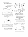
2. Thermostat
The thermostat is of wax type, designed to start opening
its valve at 76.5 ± 2°C (169.7 ± 3.6°F) of risingtemperature and opens it fully at 90°C (194°F), lifting it off
the seat by 9 mm (0.35 in.).
2-1 Disassembly
(1) Remove thermostat cover (2) by loosening bolts
(1).
(2) Take out thermostat (3).
- 52-
~#-""is:::~r-~~L~ift~:~9 mm (0.35 in.l
2-2 Inspection
E
E
Clean the thennostat, place it in a hot-water tub, and
test it for thennostatic action by heating the tub to
raise the water temperature. The valve should start
opening at 76.5 ± 2°C (169.7 ± 3.6°F) and be fully
open at 90 ± 2°C (194 ± 3.6°F) with a valve lift of not
less than 9 mm (0.35 in.). A thennostat whose valve fails
to operate in this manner in the test must be replaced
with a new one.
~
.,
9
>
iii
>
0
Tl:
Temperature [76.5° ± 2°C (169.7°± 3.6°F)1
that makes valve start opening
Tz:
Temperature [90° ± 2°C (194° ± 3.6°F)]
that makes valve fully open with a lift of
not less than 9 mm (0.35 in.)
Thermostat performance curve
3. Water pump
The water pump is of centrifugal type. Its bearings are
lubricated by engine oil fed from the main gallery
within the crankcase. The impeller is threadedly mounted
on the pump shaft.
@@
402553
1-Bolt
2-Cover
3-lmpeller
4-Unit seal
5-Snap ring
6-Bearing
7-Shaft
8-Bearing
9-Pump case
3-1 Disassembly
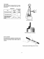
(1)
Remove pump cover (2) by loosening coverattaching bolts (1).
milO
(2)
Support the shaft with a stand to remove impel·
ler (3).
[NOTE]
Impeller is threadedly mounted on shaft. The
thread is of right-hand screw.
- 53-
(3)
Remove snap ring (6) from the water pump
shaft.
(4)
Pull shaft (8) off the pulley side on pump case
and remove bearings (7) and (9) from the shaft.
3-2 Inspection
(1) Examine the pump operation by slowly rotating it.
If the pump is erratic in rotation, replace the
bearings with new ones.
(2) Visually check the impeller for corrosion or
breakage. Replace a defective impeller. Also check
the impeller for signs of rubbing. If such rubbing is
evident, check for the cause. The impeller and case
or cover, if found damaged due to rubbing, must
be replaced with new ones.
(3) Check the unit seal for condition. Replace the seal
if it is badly worn or damaged.
(4) Check the pump shaft bearing journals for wear.
Replace the shaft if the journals are excessively
worn.
(5) Check those surfaces of pump case to which the
bearings are fitted for excessive wear or damage.
Replace the case or the pump assembly if the case
is found in bad condition on those surfaces.
[NOTE]
Upon assembling the water pump, tum it by
means of the pulley, making sure that the pump
rotation is smooth without signs of binding.
- 54-
3-3
Reassembly
(1) Install bearings (2) on pump shaft (1) and install
the shaft in pump case (3).
(2) Install snap ring (4) in case on pulley side.
(3) Install unit seal (5) in impeller (6) and secure the
impeller to the shaft.
(4) Install cover (7).
(5) Rotate the shaft to check to see that the impeller
does not interfere with cover.
- 55-
FUEL SYSTEM
1-Air vent plug
2-Fuel filter
3·Air vent plug
4-Air vent plug
5-Fuel
6-Fuel
7-Fuel
a-Fuel
injection pump
feed pump
injection pipe
injection nozzle
Fuel circuit
1. Fuel circuit
The fuel feed pump, mounted on the fuel injection
pump body and forming a part of the injection pump
unit, draws fuel from the fuel tank and delivers it
through the fuel filter to the gallery inside the injection
pump_
The injection pump is of individual plunger type, consisting of four plunger pump elements which are driven
from a common camshaft. Each pump element delivers,
intermittently, a shot of high-pressure fuel oil to its
injection nozzle through its own injection pipe. These
shots are synchronized to the diesel cycle in' each
cylinder and timed by the setting of the timing mechanism.
"Injection quantity," or the amount of fuel delivered
uniformly by the four pump elements to the engine
through their injection nozzles, is controlled from the
accelerator through a linkage and automatically adjusted
by the injection pump governor on the basis of engine
speed and load requirements.
The governor built in the injection pump body is a
mechanical all-speed governor, which limits the maximum and minimum engine speeds and actuates the
control rack of the injection pump to maintain a
constant engine speed under varying load condition at a
speed level proportional to the pOSition of the accelerator.
-56-
9-Fuel leak-off pipe
10-Fuel pipe
2. Priming the fuel system
(1) Unlock the priming pump by turning its knob
counterclockwise.
(2) Loosen the air vent plugs, and operate the pump
until overflowing fuel no longer carries air bubbles.
(3) Tighten the air vent plugs while pressing the pump
knob downward.
(4) Lock the pump by turning the knob clockwise
while pressing it downward.
3. Adjusting the injection timing
The engine with RUV governor
(1) Alignment marks (line marks) are provided on the
pump body and flange plate. Make sure that
these marks are lined up. With the pump gear and
idler properly positioned in their meshed condition
inside the timing gear case, that is, the match
marks on these gears indexed to each other, mount
the injection pump unit on the engine front plate
and secure it by tightening the mounting bolts.
(2) Install fuel feed pipes and lube oil pipe, and
reconnect all but No.1 fuel injection pipe.
(3) Crank the engine slowly until the plunger in
No. 1 pumping element comes to the position
for "beginning of injection." Check to be
sure that the timing mark on crank pulley is
matched to the pomter on the
timing gear case; if not, adjust the mounted
position of the pump in the follOwing manner:
A·Timing mark on crankshaft pulley (TDG)
(NOTE ]
Tilting the pump toward the engine advances
the timing, and vice versa'. Refer to the graduation marks provided on the edge face of the
mounting flange: one division is equivalent to
6 deg. of crank angle.
(4) Having made sure that aU timing marks are
matched as prescribed and that the beginning of
injection is correctly time'd (in reference to No. 1
cylinder), reconnect the injection pipe (No.1).
Prime the fuel circuit in the manner previously
described: make sure that no air remains trapped
in any part of the circuit.
- 57-
The engine with RSV governor
The injection timing for each model of the engine varies
according to its output, speed and specification. Be sure
to verify the timing by referring to the specifications of
each model.
(1) Bringing No.1 piston to top dead center on compression stroke
(a) Using turning bar (30691-11800) at the crankshaft pulley, turn the crankshaft in normal
direction (clockwise as viewed from the front
side of the engine).
(b) Stop cranking the engine when the timing mark
"0" on the crankshaft pulley is aligned with the
pOinter.
(c) Move the intake and exhaust valve rocker arms
for the No.1 cylinder up and down to make sure
that they are not being pushed up by their pushrods.
(2) Inspecting fuel injection timing
(a) Remove the delivery valve holder from No.1
pumping element of injection pump. Take delivery valve and spring out of the holder, and
restore the holder to the pump.
(b) Turn the crankshaft to bring No. 1 piston to
about 60° position before top dead center on
compression stroke.
(c) While operating the priming pump to allow fuel
to flow from the delivery valve holder, crank the
engine in normal direction. Reduce cranking speed
when the fuel just starts to stop flowing. Stop
cranking when the fuel stops flowing.
(d) Make sure that the timing mark on the crankshaft
pulley is aligned with the pointer.
(3) Adjusting fuel injection timing
(a) If the timing is retarded, tilt the injection pump
toward the crankcase. If it is advanced, tilt the
pump away from the crankcase.
To retard
401304
- 58-
(b) One graduation of the scale on the injection
pump coupling changes the timing by 6° in
terms of crank angle.
4. Fuel filter
The fuel filter uses a special paper element having high
flltering performance and large capacity.
4-1 Inspection
(1) Filter case and cover
Check for cracks, distortion or other damage and
also for stripped threads. Replace the case and
cover if found in defective condition.
(2) Connector bolts and plug
Check for defective threads, replacing them if
damaged.
(3) Gaskets
Discard gaskets removed in disassembly. Be sure
to use new gaskets in each reassembly.
[NOTE )
Do not wash the element for re-use.
402515
l-Bolt
2-Gasket
3-Cover
4-Air vent plug
-59 -
5-Case
6-Drain plug
7-5pring
8·Bolt
9-5pring seat
10·Element
5. Injection nozzles
The injection nozzle provides a means of spraying
into the precombustion chamber the fuel oil delivered
under pressure from the injection pump. It sprays oil out
in a conical pattern consisting of finely atomized droplets of oil. The mating surfaces of the nozzle holder
body, distance piece and nozzle are precision.finished to
form an oil·tightness.
The injection pressure adjustment may be made by
means of adjusting washer. Increasing the thickness of
the washer will increase the spring tension and, hence,
the injection pressure, and vice versa.
®--_"®
CD
,-Retaining nut
2·Nozzle tip
3·Distance piece
4-Pressure pin
5-Pressure spring
6-Washer
7-Nozzle holder
8-Gasket
9-Nut
5-1 Removal
(1) Remove injection pipe connecto rs (1) to disconnect
injection pipes (2).
(2) Disconnect leak-off pipe (3) (4) connecting nozzles
by loosening nuts (5).
(3) Using a wrench, remove nozzles from cylinder
head as shown. Also remove nozzle packings with a
wire or screw driver. Replace a defective packing,
if any.
(4) Install injection nozzles in the reverse order of
removal. Tighten nozzle holders to a torque of
5 kg-m (36.2Ib-ft).
[NOTE)
Cover the injection pipe and cylinder head
openings to prevent entry of dust or foreign
matter after removing the nozzles.
5-2 Disassembly
(1) Before disassembling injection nozzles, check
the nozzle injection beginning pressure, the spray pattern and adjust if necessary. Carry out oil-tightness
test and repair if necessary.
Exercise care not to damage the points of needle
valves during disassembly, washing and assembly of
nozzles.
(2) Hold retaining nut (1) in a vice and loosen nozzle
holder (2) with a wrench.
-60-
(3) Remove nozzle tip (3), distance piece (4), pressure pin (5), spring (6) and washer (7) from nozzle
holder.
(4) All the parts disassembled should be washed in
clean kerosene and dried with compressed air. Decarbon the nozzles removed with a wooden scraper and
clean them thoroughly in gasoline.
5-3 Inspection
(1) Needle valve and nozzle body
(a) Immerse needle valve and nozzle body in a pool
of clean kerosene, insert the valve into the
body, and move the valve back and forth to be
sure that the sliding contact is smooth without
evidencing any excessive clearance. The injection nozzle as a whole must be replaced if the
fit is found defective_
(b) Visually examine the nozzle body with a magn.
fying glass having a power of 4 or 5.
(c) Inspect the needle valve for distortion or damage at its seating part and for wear of its end
face in contact with the pressure pin.
(d) Poor seating contact may be corrected, if the
defective condition is not advanced too far, by
lapping the valve against the seat with a coat of
clean lube oil applied to the seating faces. If
this does not help, the injection nozzle must be
replaced.
(2) Nozzle holder and distance piece
Check the fit between nozzle holder and distance
piece. Determine the quality of the fit from
contact patterns obtained with the use of red lead
paste: defective fit will be evidenced by an abnormally high rate of return oil (leak-ofQ flow.
(3) Pressure spring and pressure pin
(a) Replace any pressure spring broken, cracked or
otherwise defective, or out of square. Inspect
each spring for these defects.
(b) Inspect each pressure pin for wear at its end
faces, one for pressure spring and the other for
needle valve:
(4) Leak-off pipe packing
If the packing is found in deteriorated condition,
replace it.
-61-
5-4 Testing and adjustment
(1) Injection pressure
The pressure at which the needle valve unseats
itself against the force of the pressure spring is
referred to as "valve opening pressure" or "beginning-of-injection pressure," but will be called here
"injection pressure' for short. The value 01 this
pressure is specified; it is checked and adjusted as
follows:
(a) Install the injection nozzle in the nozzle tester,
and operate the manual pumping handle of the
tester several strokes to prime the nozzle.
(b) Move the lever up and down slowly, completing
each up.and-down cycle in about a second, to
pressurize the injection nozzle, while observing
the indication of the test pressure gauge. As the
nozzle begins to spray, the indicating pointer of
the gauge being deflected will start perceptively
oscillating: read the pressure right then as the
injection pressure.
Unit: kg/cm 2 (psi)
Specifications
Item
Injection
pressure
Repair
limit
Standard
g
5.
120+ 1 (1706.4+ 14 2 )
110(1564.2)
minimum
(c) If the reading taken is below the limit, increase
the thickness of the shim used on the pressure
spring. Increasing the shim thickness by 1 mm
(0.04 in.) raises the injection pressure by
about 10 kg/cm 2 (142 psi). Adjusting shim
stock for this purpose is available in 20 sizes,
from 1.0 mm (0.0394 in.) up to 1.95 mm
(0.0768 in.) in increments of 0.05 mm (0.0020
in.) each.
(2) Spray pattern
The injection nozzles used in the present engine
are of throttle type. Some throttling action takes
place when the needle valve begins to unseat,
thereby limiting the amount of fuel being sprayed
out during the initial stage of each fuel injection.
Thus, each slug of fuel sprayed out may be
regarded as consisting of two parts: initial throttled
spray and tenninating main spray.
1
2
3
lllJ
lUI
II!lI
1\
When tested on the nozzle tester, the injection
nozzle can be made to produce these two kinds of
spray for visual inspection. Initial throttled spray
comes about when the tester lever is operated at
a rate of 60 cycles per minute (up and down 'in
one second); terminating main spray occurs when
the lever is operated rapidly at a rate of, say, 4 to
6 cycles per second.
-62-
1-Good
2-5pray cone too large
3-Off-i:enter spray
4·After-dribble
5·Fissured spray
6-Whirling spray
Possible patterns of spray
(a) Initial throttled spray
When the nozzle is producing only this spray,
atomization is generally poor and the pattern is
rather straight than conical, there being more
or less after-dribble, that is, fuel dribbling after
injection. All these are due to the fact that the
fuel being injected is being throttled by the
pintle prptruding from the valve.
While the nozzle is making this spray, see if the
needle valve chatters in synchronism with the
cyclic motion of the lever; if so, then the needle
valve is free from any sticking or hitching
tendency and, if not, the nozzle and needle
valve must be cleaned by washing and re-tested.
Off-center spray or directionally erratic spray,
if noted, should be taken to mean that the
injection nozzle needs thorough cleaning.
(b) Terminating main spray
With the tester lever operated at a rate of 4 to
6 cycles per second, the initial throttle spray is
hardly visible. The spray under this condition
may be regarded as main spray.
The main spray should be a good straight cone,
consisting of fmely atomized fuel particles
without any large droplets, and should terminate with no dribble at the tip, not to mention
of any fuel dripping.
(3) Seating tightness
An injection nozzle tested and adjusted as above,
and found to produce a good spray pattern may
be re-used in the engine provided that it passes
this fmal test - seating tightness test.
With the injection nozzle mounted on the nozzle
tester, raise the pressure slowly to 100 or 110
kg/cm 2 (1422 or 1564 psi) (without exceeding the
set pressure of 120 kg/cm2 (1706 psi), so that the
needle valve will not unseat). Hold the pressure
and observe the nozzle tip: there should be no
evidence of fuel oozing out to form a dribble. If
such evidence is noted, then the contacting faces
of the needle valve and seat must be repaired by
lapping in the manner already suggested or the
injection nozzle as a whole must be replaced.
-63 -
5-5 Reassembly
Assemble injection nozzles in the reverse order of
disassembly. Be sure to assemble nozzle assembly in kerosene.
\\hen using new needle vavles, remove sealing cover (synthetic resin) from the valves and wash them in kerosene
to remove rust and corrosion inhibitor sprayed over them
by sliding the valves in the nozzles immersed in kerosene.
[NOTE]
If the needle valve and nozzle proper have to be
replaced, be sure to wash the replacement parts
in the pool of kerosine after removing their
protective fIlm of plastic: wash off the rustpreven tive oil from the nozzle proper by
stroking the needle valve back and forth in the
needle valve stem bore.
6. Fuel feed pump
The camshaft in the bottom section of the injection
pump has an eccentric cam besides the cams for actuating the individual pump elements. By this eccentric
cam, the pumping plunger of the feed pump is actuated
to draw fuel through the inlet strainer and forward it
to the injection pump.
_1I+-_~7
A means of manually priming the fuel circuit is provided
in this pump. It consists of a plunger and a knob.
Pushing the knob in rapid repetition sends the fuel
forward. The fuel circuit from the feed pump through
the fuel ftlter to the injection pump can be primed in
this manner. This feature is utilized also in bleeding air
out of the fuel circuit.
402657
1·Feed pump housing
2·Check valve
3·Valve support
4-Hollow screw
5-Piston and tappet
-64-
6·Check valve
7·Priming pump
8-Valve holder
9-Gauze fi Iter
1O-Hollow screw
6-1 Disassembly
(1) Remove valve holder (1) and priming pump (2)
and take out check valve (3). Priming pump cannot be
disassembled as the cylinder and valve holder are adhered with adhesives.
(2) Loosen piston chamber plug (4) and pull out
piston spring (5) and piston (6).
(3) Remove ring (7) and take out tappet (8) and push
rod.
-65 -
6-2 Inspection
(1) Check valve
Inspect the seating faces of the check valve for
wear, and replace parts found in abnormally or
excessively worn condition.
(2) Tappet wear
Mike the tappet and tappet hole to determine
their diametral wear. Replacement is necessary if
the amount of wear noted in comparison with the
standard diameter is 0.1 mm (0.004 in.) otmore.
Specifications
Unit: mm (in.)
Item
Standard
Service
limit
Tappet OD
20 (0.78)
0.1 (0.004)
Tappet hole ID
20 (0.78)
0.1 (0.004)
The overall play of tappet roller pin, involving the
pin hole and roller, is prescribed to be not greater
than 0.3 mm (0.012 in.). If this limit is exceeded,
the whole tappet sub-assembly must be replaced.
Replace the roller if its diameter has worn down
to the service limit.
Specifications
Item
Standard
Unit: mm (in.)
Service
limit
+0
15 -0.027
Tappet roller OD
(0.591 j.00106)
-0.075
(-0.00295)
(3) Pump housing damage
Inspect the housing for cracks, broken screw
threads and other types of damage and repair or
replace it as necessary.
(4) Priming pump wear
Inspect the piston and cylinder for scratch marks,
wear and rusting. Check the seating faces of its
valve for wear. An excessively worn or damaged
seating face must be corrected by replacement.
-66 -
6-3 Testing
The feed pump IS m satisfactory condition when it
meets all of the test requirements hereunder enumerated:
(1) Suction perfODnllJlee
The pump should be capable of starting to deliver
fuel in 45 seconds of its starting at 150 rpm.
(2) Delivery preauae
Run the feed pump at 600 injection-pump rpm,
with the discharge side of the feed pump fully
closed. Under this condition, the delivery pressure should be anywhere between 1.S kg/cm 2
(25.6 psi) and 2.2 kg/cm2 (31.3 psi).
Specification
Unit: kg/cm l (psi)
Standard
hem
Feed pump delivery
pressure
1.8"" 2.2 (25.6"" 31.3)
at 600 rpm
(3) Capacity test
Run the pump at the speed specified below and
open the discharge side more or less to hold the
discharge pressure at 1.5 kg/cm l (21.3 psi) (as
read on the test gauge), with a measuring glass
cylinder set up to receive the discharged fuel.
Under this condition, the pump should'deliver at
least 900 cc (54.9 cu in.)/miDute.
Specifications
Item
Feed pump
capacity
Standard
900 cc (55
cu in.)/minute,
minimum at
1000 rpm
Repair limit
600cc (37
cu in.)/minute,
at 1000 rpm
(4) Air-tightness
Air pressure,
2 kg/cm l (28 psi)
Immerse the feed pump in a pool of fuel, with its
discharge side plugged up. Apply an air pressure of
2 kg/cml (28 psi) to its suction to see if any
bubbles come out of the pump. Some air, however,
will leak out through the clearance between its
pushrod and housing. The pump is sufficiently
air-tight if the amount of this leakage (with no
leakage from any other part of the pump) is not
greater than the value specified.
Specification
Item
Standard
Feed pump air-tightness
Not greater than 50 cc
(3.1 cu in.)/minute (with
bubbles not larger than
2mm(0.OS in.) in size)
If the air-tightness is poor, replace the pump
housing sub-assembly (including housing, push rod
and oil seal).
-67 -
---,~
1-Measuring cylinder
2-Tappet
3-Plug
4-Diesel fuel oil
7. Fuel injection pump
, -Bearing cover
2-Tapered roller bearing
3-Governor housing
4-Tapered roller bearing
5-Screw plug
6-Pump housing
7-Delivery valve spring
8-Delivery valve
9-Alr vent screw
, O-Delivery valve seat gasket
-Tappet
'2-Cover
l'
The pump body is an aluminum alloy casting IDCl
houses all the moving parts of pump elements and
the camshaft. The governor housing is attached to
one end of the pump body.
The camshaft is supported by two tapered roDer
bearings. Like the engine camshaft, it has four
cams, one for each pump element, and is driYen
from the crankshaft through a train of gears
arranged for a gear ratio of 2 to 1. For each two
rotations of crankshaft, the injection pump camshaft rotates once.
The pump element consists of a plunger, barrel
(cylinder), tappet, plunger spring, control pinion
and spring-loaded delivery valve. The tappet rides
on the cam and pushes the plunger upward for
each rotation of camshaft. As the plunger rises,
the fuel in the barrel becomes compressed and is
forced out through the delivery valve into the
injection pipe_ The upward plunger stroke, effective in compressing or pressurizing the fuel, is
variable, and is varied by means of the control
rack and pinion in the manner to be explained
later.
-68-
, 3-Camshaft
'4-Drain plug
, 5-Del ivery valve holder
, 6-Delivery valve seat
17-CYlinder
,a-Plunger
, 9-Control rack
20-Upper spring seat
2' -Control sleeve
22-Spring
23-Lower spring seat
24-Shim
The delivery valve, through which a shot of fuel is
forced out into the injection pipe by each upward
motion of the plunger, is essentially a check valve
having a special function of qUickly reducing the
line pressure the moment the plunger begins to
descend. This quick relief of line pressure is
necessary to prevent the injection nozzle from
dribbling at the end of each injection. How this is
accomplished will become clear.
Tabulated data
Cam lift
8 mm (0.315 in.)
Plunger diameter
6.5 mm (0.256 in.)
Delivery valve dia.
6 mm (0.236 in.); retraction
volume 51 mm 3
(0.003 cu in.)/stroke
Injection order
1-3-4-2
Injection interval
90 ± 30'
0
8. Governor
l·Stopper lever
2-0il inlet
3-Control spri ng
4-Screw plug
5-Stopper
6-Control lever shaft
7-Shackle pin
8-Floating lever
9-Connecting pin
10-Connecting bolt
11-Supporting lever
l2·Arm
l3-Shackle
l4-Flyweights
l5-Bearing
l6-Governor gear
l7-Slip disc
l8-Shim plate
19-Camshaft
20-Camshaft bushing
2l-Control lever shaft
22-Drain plug
23-Bearing
24-Shim plate
25-Governor sleeve
26-Adaptor spring
27-Adaptor
28-Torque spring
29-Adjusting nut
30-Cap nut
3l-Shaft
-69 -
32-Governor shaft
33-Spring seat
34-Spring seat
35-Torque control lever
36-Round nut
37-Governor cover
38-Governor housing
39-Torque control lever
40-Shaft
4l-Adjusting lever
The governor is an all-speed governor operating in
response to changes in engine speed to actuate the
control rack in order to maintain engine speed at a
constant level proportional to the set position of
the accelerator. This governor function is in sharp
contrast to that of a minimum-speed maximumspeed governor, whose control action is to limit
the lowest and highest speeds of the engine, leaving
the control of intermediate speeds to the operator.
The construction of the governor is as illustrated in
the figure above:
The governor consists essentially of governor gear
@' flyweights rJ], governor sleeve:§) and speed
control spring @.
The governor gear is mounted on camshaft bushing
attached to the rear end of the injection
pump camshaft with round nut (§l and is pressed
by slip disc @' so that it is not damaged even
when the engine output torque varies.
®
The flyweights are mounted on governor shaft.
The radial movement of the flyweights due to
centrifugal force is transmitted to arm @ to push
governor sleeve @ through thrust bearing. To
this sleeve is attached adaptor spring @. This
spring opposes the force of control spring ®
through spring seat so as to compensate for a
decrease in torque when the engine is running at
low speeds. Floating lever ® is hinged at its lower
end to supporting lever (IT) mounted on control
lever shaft C§.:) and is connected at its upper end to
control rack through shackle @l. To the mid·part
of this floating lever is fitted connecting pin ®
through which the movement of the flyweights is
transmitted to the control rack. Damper spring,
which is mounted on the end of control rod, serves
to prevent engine hunting as when the engine
speed is suddenly decreased. Stopper lever CD is
provided to move the contro: r~ck to "stop" posi·
tion.
Engine stalling, which may often occur when the
load is suddenly increased, is prevented by torque
spring. The timing mark provided on the camshaft
bushing and the timing pointer on the governor
housing are conveniently utilized in determining
the beginning of injection in the No. 1 cylinder
during assembly job.
A-Timing mark
Timing mark on injection pump
-70-
ELECTRICAL SYSTEM
1. General
Model
Starter
Manufacturer
MOO2T54172
Mitsubishi Electric
Alternator
AOO1T25070
Mitsubishi Electric
Glow plugs
Sheathed type
Hiyoshi Electric
Battery charge lamp
Glow plug indicator
Starter switch
Glow plugs
Wire sizes
s
-
40 ODd
5 ODd
- - 1.25 ODd
- - 0.5 ODd
Battery
-
12V - 100AH
Wiring diagram
-71 -
1-1 Starter
(1) Tabulated data
Model
M002T54172
Type
Pinion-shift type with overrunning clutch
Voltage
12V
Output
2 kW
Armature winding
Series
Yoke diameter
80 mm (3.15 in.)
Rating
30 seconds
Rotation
Clockwise as viewed from pinion side
Weight
5.8 kg (12.8 lb), approx.
Performance item
Specification
Condition
No-load characteristics
Voltage: 11 V
Current
Speed
130 A, max.
4000 rpm, min.
Locked characteristics
Voltage: 3 V
Current
Torque
1000 A, max.
2.8 kg·m (20.3 lb·ft), min.
8 V, max.
Switch-in voltage
a-Gear
9-Center bracket
10-Yoke
11-Armature
12-Brush holder
13-Rear bracket
1-Switch assembly
2-Front bracket
3-Lever assembly
4..spring set
5-Bearing
6-Pinion
7-Pinion shaft
-72-
tated into the free state by the springs to unlock
the inner and outer races. This allows the pinion
to spin independently of, or overrun, the remainder of the clutch.
(2) Reduction gear train and overrunning clutch
The inner end of armature shaft carries a drive
gear which is in mesh with a driven gear splined
to the pinion shaft to provide speed reduction.
The pinion shaft is fitted loosely to the outer
race of overrunning clutch through helical spline
engagement. The pinion is fitted to the sleeve the inner race of the dutch - and held in place
by a snap ring.
(4) Starter operation
(a) Starter switch (SW) in OFF position
Main contactor
Five clutch rollers are fitted between the outer
race ( thrust splines) and inner race (sleeve) of
overrunning clutch, each being pressed against
the cam face internally formed of the outer race
by a spring.
Field coil
Armature
Thus the drive or torque is transmitted from the
armature shaft through the reduction gears, pinion
shaft, thrust splines (clutch outer race), rollers and
sleeve (clutch inner race) to the pinion.
T
-.L Battery
1
(b) Starter switch (SW) turned to ON position
(3) Overrunning clutch operation
Armature
T
-.L Battery
!
The plunger is pulled. This allows the lever to push
the pinion into mesh with the flywheel ring gear.
Now the starter begins to crank the engine.
(c) Starter switch (SW) in ON position
(with contact or closed)
1-0uter race
2-Roller
3-Spring
,,
Main contactor
Pinion meshed in
flywheel
Engine starts
4-lnner race
5-Pinion
Field coil
(a) Pinion meshed in flywheel
Starter switch
(SW)
As the outer race rotates, the rollers are jammed
tight between the inner and outer races to lock
these races. Now the torque from the armature
is transmitted from the outer race to the inner
race and then to the pinion.
Armature
T
-.L Battery
!
A large current flows into the motor. The starter
now cranks the engine with full force while picking
up speed at the same time.
(b) After the engine starts, it spins the pinion (inner
race) faster than outer race. The rollers are ro-
-73 -
1-2 Alternator
1-Rotor
2-Bearing
3-Pulley
4-Stator
5-Front bracket
6-Rear bracket
(1) Tabulated data of alternator
(2) Construction of alternator
Model designation
AOOIT25070
Nominal output
12V-35A
Polarity of ground
Negative
Outside diameter
114 mm (4.48 in.)
Direction of rotation
Weight
Regulator
Voltage regulation
7-IC regulator
a-Rectifier
9-Bearing
This alternator has a built-in IC regulator. The
rotary parts are: rotor, ball bearings, fan and pulley.
The stationary parts are: stator, front bracket and
rear bracket.
The rectifier consists of a total of six diodes: three
diodes on the positive side are mounted on the
heat sink and the other three on the negative side
are mounted on the rear bracket.
Clockwise as viewed from
pulley side
3.4 kg (7.5 lb)
IC type
14.4 ± 0.3 V
-74-
(3) Alternator operation
(a) Starter switch in M position
....._..JI~'--_Fuse box
--
Alternator
t
Ie regu lator
,······1.-"
Battery
....
(b) Starter switch in S position and starter operates
'--_....JJ7f\..l'--_
Fuse box
,······1.-"
Battery
-75 -
....
(c) Engine starts and alternator charges battery
~----------------~B~------------------~
IC regulator
..............-otl·····
·1,
Battery
":"
(d) Alternator charges battery excessively
~~--------------~B~----------------~~
Fuse box
IC regulator
......--tII······I..-,.
Battery
When output voltage has sufficiently dropped,
zener diode Dz permits no current to flow. Now
transistor Ql turns off and transistor Q2 turns on
and, consequently, the field current increases and
output voltage rises again. This process is endlessly
repeated to keep output voltage at a virtually
constant level.
As alternator output voltage rises higher than the
regulated voltage, zener diode Dz permits the
current to flow to the base of transistor Qt.
As transistor Ql turns on, the current flows from
the three diodes to transistor Ql, causing transistor
Q2 to turn off. Under this condition, the field
current is reduced to weaken excitation of the rotor
and, consequently, output voltage begins to fall.
-76 -
":"
2. Starter removal and installation
(1) Disconnect wire (1) between the battery and starter
and wire (2) between the starter and starter switch.
(2) Unscrew mounting nuts (1), and remove starter assembly (2) from the engine. To install, follow the
reverse of removal procedure.
1-N ut and washer (2 pcs each)
2-Starter assembly
-77-
3. Starter disassembly and reassembly
13
16
15
14
8
10
1-Switch
2-Rear bracket
3-Brush holder
4-Yoke
5-Armature
6-Ball bea(ing
7-8all bearing
a-Cover set
9-Center bracket
10-Gear
11-Spring set
12-Lever
13-Pinion set
14-Pinion shaft
15-0il seal
16-8all bearing
17-Front bracket
(The parts are numbered in the sequence of removal for disassembly.
To reassemble, follow the reverse of disassembly procedure.)
(1) Loosen the nut on the switch terminal (M), and
remove the connector. Remove the switch by pulling the screws (2 pcs).
(2) Pull the through bolts (2 pcs), remove the brush
holder screws (2 pcs) and remove the rear bracket.
(NOTE)
Take care not to drop the washers which are
used in the rear bracket.
-78-
(3) Remove two brushes on the positive side, and take
off the brush holder.
(6) Remove the center bracket by unscrewing two bolts.
Remove washers (several pieces) for adjusting the
pinion shaft axial play.
(4) Remove the yoke, and pull off the armature.
(7) Remove the snap ring holding the pinion, and remove the pinion.
[NOTE]
(8) Remove the lever springs (large and small), lever,
reduction gears, pinion shaft, etc.
Replace rubber packings fitted to the ends of
yoke with new ones. Check and record the position of locating notch for the yoke.
[NOTE]
Lay the lever and springs in the order removed
so that they can be restored to their original
positions.
(5) Remove the cover, and take off the washer and
snap ring.
(9) Replace the ball bearings. The ball bearings fitted
to the ends of armature can be removed with a
bearing puller. The front bracket bearing and
sleeve bearing (fitted to the inner race of ball
bearing) cannot be removed for replacement.
These bearings are to be replaced as an assembly
including the front bracket.
-79-
4. Alternator removal and installation
(1) Pull the three through bolts, and break the alternator into the rotor (complete with front bracket
and pulley) and stator (complete with rear bracket).
(1) Disconnect wire (1) between the alternator and
relay and ground harness, unscrew the adjusting
plate bolts, and remove the fan belt.
(2) Unscrew bolts (2) securing the alternator bracket,
and remove alternator assembly (3) from the engine.
1-Bolt (3 pcs)
2-Front bracket
3-Rotor
4-Stator coil
5-Rear bracket
6-Pulley
(2) Hold the rotor in a vise. Unscrew the pulley nut,
and remove the pulley.
1-Bolt and washer
2-Bolt, nut and washer (2 pcs each)
3-Alternator assembly
5. Alternator disassembly and reassembly
o.~
2-F ront bracket
3-Rotor
670355
1-Bolt (3 pcs)
2-Front bracket
3-Rotor
4-Stator coil
5-Rear bracket
6-Pulley
7-Fan
8-Diode
9-Brush
10-Nut
6-Pulley
7-Fan
(3) To reassemble, follow the reverse of disassembly
procedure. Lift two brushes up into the brush box
and pass a pin through the screw holes in the box
and brushes to keep the brushes depressed. After
reassembling the alternator, be sure to remove the
pin.
Brush
Pin
\
670220
-80-
Do not jump into a conclusion that th.e starter
is in trouble when the engine refuses to fire up
upon cranking: the engine could be in trouble.
6. Preheating system
Removal and installation of glow plugs
(1) Before removing glow plugs from the engine, be
sure to disconnect battery terminals.
(b) No-load test
(2) Disconnect cable (1) from No.4 cylinder glow plug.
Loosen glow plug connection plate attaching nut
(2) and remove connection plate (3).
If the starter is suspected of trouble, take it
down from the engine and run a no-load test
on it to find out if it is really in trouble.
When removing the starter, be sure to have the
battery switch turned off.
Switch
-EB
I
I
-9
J8843
No·load test circuit
402591
'·Cable
3-Connection plate
2·Nut
(3) Remove all glow plugs from the cylinder head.
Take out packings from glow plug installation holes.
(4) To install, follow the reverse of removal procedure.
7. Inspection and adjustment
7 -1 ·Starter
(1) Inspection before disassembly
(a) Checking the starting circuit for operation
With the starter in place, check to be sure that 1) The battery is in good condition, with its cell
plates showing no evidence of "sulfation" or
any other faulty condition, and is in fully
charged state.
2) The battery terminal connections are clean
and tight.
3) The starter terminal connections are tight.
4) The wires are securely connected to terminals,
and are free of any insulation stripping due to
fraying, there being no signs of grounding or
breaking.
5) The starter switch closes and opens the circuit
positively at each position.
- 81-
Here's how to carry out the no-load test: Form
a test circuit with a voltmeter and an ammeter,
as shown, using a fully charged 24-volt battery;
close the switch to run the starter until its speed
rises to and above 4000 rpm; and then read the
voltmeter and ammeter when the starter is spinning. The ammeter should show that the starter
is drawing not more than 130 amperes, with the
voltmeter indicating at least 11 volts (at the speed
of at least 4000 rpm); if not, estimate the cause
of the trouble by consulting the troubleshooting
guide, which follows:
Starter troubleshooting guide
Symptom
Possible cause
1) Bearings are dirty, or need
lubrication.
Large current
and low speed
2) Rotor (armature core) is
rubbing the pole pieces.
3) Grounded coil in the armature
or in the field.
4) Short-circuit in the armature
coils.
670202
1) Magnetic switch is grounded
and is not working.
Large current
but no speed
(b) A growler is generally used to test armature for
short circuit in its Winding. Place armature on a
growler, and rotate it slowly while holding a steel
strip over armature. If there is any short circuit
between cores, the strip will vibrate and be attracted to armature. If so, replace armature.
2) Grounded coil in the armature
or in the field.
3) Seized bearing.
1) Open-circuited coil in the
armature or in the field.
No current and
no speed
Small current
and low speed
and torque
2) Broken brush pigtail.
3) No conduction between
brushes and commutator
because of "high mica" condition or dirty commutator
surface.
Loose coil connection in the field.
Very large current,
very high speed
Short-circuited field coil.
and low torque
The best way of testing the starter is to run it
under loaded condition, but that requires special
testing equipment. For ordinary servicing purposes, the no-load test and troubleshooting guide
will do.
(c) Measure commutator runout with a dial gauge.
Repair commutator if the runout exceeds the
limit.
(2) Inspection after disassembly
(a) Using a ground tester or megger, check armature
coil and commutator for short circuit. If there
is any continuity between commutator and armature shaft, armature coil and commutator are
short circuited.
Specifications
-82-
Unit: mm (in.)
Item
Assembly
standard
Repair
limit
Grinding
limit
Commutator
runout
0.05
(0.0020)
0.3
(0.012)
31
(1.22)
(d) Brushes and brush springs
Pinion gap
1) Measure brush length. Replace brush if the
length exceeds the service limit.
Battery
12 V
Pinion
Specifications
Item
670208
Pinion gap
Specifications
Item
Brush length
I
Assembly standard
0.5
(0.020
~
~
2.0
0.079)
Unit: mm (in.)
Assembly
standard
Service
limit
18
(0.71 )
11
(0.43)
I
Unit: mm (in.)
[NOTE]
To adjust pinion gap, increase or decrease
thickness of washers used between mating
faces of magnetic switch and front bracket.
2) Using a spring balance and new brush, check
spring pressure. Replace spring if the pressure
is below the service limit.
(f) No-load test
After adjusting pinion gap, connect starter and
battery with an ammeter and voltmeter as
shown, and test starter for performance.
[NOTE]
Use thick wires and tighten terminal securely.
If current and speed meet the following specifications when battery voltage is 11 volts, starter
is satisfactory:
Specifications
Current
Specifications
Item
Unit: kg (lb)
Assembly
standard
Service
limit
3.5 (7.7)
2 (4.4)
Spring pressure
l30 (A), max.
Speed
4000 rpm, min.
Switch
Ammeter
(e) Pinion gap adjustment
Connect starter and battery as shown to allow
pinion to shift against stopper. Under this condition, push pinion back, and measure gap.
-83 -
(2) Regulator voltage test
(a) Test on a test bench
(3) Alternator inspection after disassembly
(a) Inspection of each diode
Use a fully charged battery. Close the switch,
and gradually increase the alternator speed.
Make sure that the current is below 5 amperes
and the voltage is 14.1 to 14.7 volts when the
alternator speed reaches 5000 rpm. If this
requirement is nor met, replace the regulator
assembly. It is impossible to reset the regulator
voltage.
Check for continuity between the wire lead and
the heat sink. Any continuity, if noted, means
that the diode is shorted; no continuity means
an open diode.
I
I
I
-"'-
I
Checking diodes
(b) Field coil inspection
(b) Test on a machine
Connect a voltmeter in the circuit between
the terminal L and ground. Turn on the
battery switch to make sure that the voltage
is 0 (zero). If the voltmeter needle defects,
the alternator is defective, or the circuit is
misconnected. With the ammeter terminals
short-circuited to prevent the starter current
from flowing to the ammeter, start the engine.
The field coil is in good condition if the resistance
between the slip rings is approximately 14.3 ohms
at a temperature of 20°C (68°F).
If the charging current is below 5 amperes when
the engine is running at about 2000rpm, read the
voltmeter.
If it exceeds 5 amperes, charge the battery for a
while, or replace the battery with a fully charged
one. Another method is to connect a 1/4 ohm
(25 W) resistor in series with the battery to limit
the charging current.
The regulated voltage should be 14.1 to 14.7
volts; if not, replace the regulator assembly.
Checking field coil
Battery switch
+
V
Ammeter
Volt meter
Battery
i
r
-84-
(3) Inspection of brushes and commutator
(a) Check the brushes for wear. A brush worn down
excessively should be replaced by a new one.
When the brush is replaced, grind the brush against
the commutator surface by using #250 sandpaper
so that it makes a full-face contact with the commutator.
(b) Check the mica insulation for condition, It should
be "undercut," that is, the segment between two
adjacent mica should be slightly proud of the mica
surface, as viewed in the cross section. Since the
commutator surface is subject to gradual wear, a
point will be reached in the course of service,
where the segments become flush with the mica.
If the commutator in such a condition is kept in
service, the mica will tend to interfere with the
satisfactory commutation. Before this point is
reached, it is necessary to recondition the commutator surface by regrinding or sanding with
#400 sandpaper and to undercut the mica properly, as shown below:
Mica
while keeping the terminal voltage at constant
13.5 volts, and read the ammeter at 2500 rpm.
The alternator is satisfactory if the ammeter
registers at least 30 amperes.
:
Amm,,,,
K1
1
..,.
~
Battery:
_v Volt met"
-
""
(c) Output test on a machine
Place a switch in the circuit between the battery
and alternator. With the switch kept open, connect
an ammeter (60-ampere class) and a voltmeter
to the circuit.
Make sure that the voltmeter registers the battery
voltage when the switch is closed.
Wrong
Start the engine, and turn on the lamp switch.
Increase the engine (alternator) speed, and read
the ammeter when the alternator speed is 5000
rpm. The alternator is satisfactory if the ammeter
registers at least 70% of the nominal output.
Right
Checking mica insulation
[NOTE]
7-2 Alternator
This test is a first-aid test. It is recommended
that the alternator be tested on a test bench for
close inspection.
(1) Alternator and regulator inspection before
disassembly
(a) If charging system is found defective, check
for items below before making adjustment or
repair:
• Fan belt tension
• Loose connections, open short circuit in
charging system wiring
• Trouble of charging system due to defective
battery
+
Battery
Volt meter
(b) Output test on a test bench
Remove the alternator from the engine.
Connect it in a test circuit as shown at upper right,
and operate it by a motor for testing.
Close the switches Kl and K2under the state
where very little load current flows in the test
circuit by varying load resistance to the maximum. Gradually increase alternator speed
- 85-
T
,,
~
I
(c) Armature inspection
7-3 Battery
Alternatively check four wire leads of the armature
coil for continuity with a tester as shown:
Check the electrolyte level in the battery cells, making
sure that it is 10 mm (5/16 in.) above cell plates. Check
the specific gravity of electrolyte. If it is below 1.260 at
20°C (68°F), prepare an electrolyte of 1.260 specific
gravity and add it to the battery. A specific gravity below
1.190 means that the battery is half discharged; in such
a case recharge the battery.
Checking armature
If there is no continuity between the wire leads,
it is an indication that the armature has open circuit. Replace the armature with a new one. Then,
check the armature for continuity between the
wire lead and core. If there is continuity, it is an
indication that there is a grounded circuit between
the wire and core. In this case, too, the armature
should be replaced.
Checking electrolyte specific gravity
7 -4 Glow plugs
Connect the positive (+) lead to the portion A of the plug
with the portion B grounded to see if the plug glows red.
The plug is in good condition if it glows red.
(d) Brushes
Any brush which is worn beyond the service limit
should be replaced with a new one.
Wear limit line
Checking glow plug
J20198
-86-
BENCH TEST
When the engine is overhauled, it is advisable to conduct
the bench tests for checking the engine performance.
The purpose of bench tests is to make sure that each
major component has been properly serviced.
(f) The relationship between the load and runningin period is as follows:
After running-in the engine, check the valve
clearance.
1. Visual inspection
Couple the engine to the dynamometer and inspect as
follows:
Engine speed
rpm
1000
1500
2000
2500
(1) Starting the engine
(a) Check the amounts of cooling water, lubricating
oil and fuel oil. Bleed air out of the fuel system.
(b) Place the starter switch in PREHEAT position to
preheat the combustion chambers. The glow plug
indicator lamp will glow red within 20 seconds. If
not, check the preheating system for condition.
Load PS
0
7.5
15
20
Time min
30
30
60
60
2. Perfonnance tests
(c) Place the starter switch in START position to
start the engine. Do not move the governor controllever to INCREASE position.
(1) Test condition
(d) After starting the engine, manipulate the governor control lever to run the engine at idling speed.
(2) Test items
The engine must be equipped with the air cleaner
and alternator.
(2) After starting the engine
• No-load maximum speed test (governor set)
• Fuel injection quantity test (control rack set)
Check the following items and repair if necessary.
• No-load minimum speed test (idling speed set)
(a) Abnormal oil pressure and oil leakage.
(3) Test procedures (with dynamometer pointer in
OFF position)
(b) Abnormal noise.
If knocking is heard while water temperature is
low and the noise dies away as water temperature
rises, the engine is in good condition.
(c) Color of exhaust gases.
(d) Leakage of cooling water.
(a) No-load maximum speed test (governor set)
While the temperatures of cooling water and oil
are still high after engine running-in, set the noload maximum speed.
(b) Fuel injection quantity test (control rack set)
(e) Leakage of fuel oil.
The fuel injection quantity can be set by means
of the governor fuel set lever. Loosening the set
screw at the top of the fuel set lever will increase
the fuel injection quantity, and vice versa.
(f) Fuel injection.
(3) Running-in the engine
While running-in the engine, check the following
items and repair if necessary.
(c) Move the control lever toward LOW SPEED position and adjust the stop screw to set the idling
rpm to 650 to 700.
(a) Oil pressure (3 ~ 4 kg/cm 2 or 42.7 ~ 56.9 psi).
(b) Temperature of cooling water (75 ~ 85°C or
167 ~ 185°F).
(d) Tune-up of engine output
(c) Temperature oflubricating oil (60 ~ 70°C or
140 ~ 158°F in oil pan).
(d) Abnormal noise.
(e) Excessive blow-by, water leakage and oil leakage.
- 87-
The diesel engine output is based on the atmospheric pressure and temperature. Therefore, the
output must be tuned up under standard conditions. Multiply the output measured by the factor.
This factor can be computed by the following
equation.
760 - 11.4
K= H-Hw
Where: H
Hw
t
/273 + t
293
atmospheric pressure
inmmHg
partial pressure of vapor in
atmosphere in mmHg
room temperature in °c CF)
-88-
MAINTENANCE STANDARDS
Unit: mm, (in.)
----
Group
Nominal
dimension
Item
Maximum rpm
(no-load)
Assembly standard Repair limit
[Standard clearance] [Clearance]
Varies according to customers' specifications.
2
Compression pressure
.
Engine oil pressure
QJ
Valve
timing
In take valves
[3mm
(0.12irt)
added
to valve Exhaust valves
side 1
20 kg/cm 2
(284 psi)
3 -4 kg/cm 2 (43 -57 psi)
(at 1500 rpm)
2 kg/cm 2
(28.4 psi)
kg/cm 2
0.5 kg/cm 2
(7.1 psi)
Open
24° ATDC
Close
4° BBDC
Open
16° 'BBDC
Close
28° BTDC
Oil and water temperatures:
20 - 30°C (68 - 86°F)
Oil temperature:
70°C (158°F)
These values are to be referred
to in measuring timing and
differ from actual timing.
'"I
~ngi.ne specifications (rpm) 1150011800 I 2000122001250013000136001
E'BTIJ('( )
1
23
I
24
I
25
I
26
1
28 I 30 I 33 I
Standard values are shown.
Check timing on caution plate.
A-"lt-,=.::- - -
Warpage of gasketed surface
0.05 (0.0020), max
Regrind if warpage is
minor.
0.20
(0.008)
..
....'"
co
0..
~
.s:
0
S
=
. c;;
S
"1:1
cco
QJ
'"co
u
~
.
:;;
u
Inside diameter
Cylinder
sleeve
I
Remarks
Asjust governor.
13°
Fuel injection timing
00
26 kg/cm (370 psi), min
(at 150 - 200 rpm)
1-2
04.2 -28.4 psi), min
(at idle speed)
cQJ
'-'
Remedy
650 -700
Minimum rpm (no-load)
;a
Service limit
[Clearance]
84 (3.307)
+g.035 tg.00138)
Out of roundness
0.01 (0.0004), max
Taper
0.Q15 (0.0006), max
+0.20
(+0.008)
0.70
(0.0276)
-r----_'"'"..,. -- F
: -fJiGQ'
--- 1--:- :
B-~_-G
I
,
I
I
C
0
E
All sleeves should be finished
to the same oversize. Hone
cylinder bore to
Hone sleeve to 0.25
(0.0098), 0.50 (0.00197) 8To.010(3425-0.00039)
or 0.75 (0.0295) oversize
-0.045'
-0.00177
with prescribed tolerance. and heat the crankcase .
Oversize pistons and
Press sleeves into crankcase and
piston rings should be
machine each sleeve lD to
used.
assem bly standard.
a9
EEl
Unit: mm (in.)
Nominal
dimension
Item
Group
Clearance on
crankshaft
journal
(in two directions at right
angles 10 each
other with bearing in place)
~c.
~
a
U
1) Replace crankcase and
bearing cap as an assembly.
2) Upper bearing shells have
oil groove.
/1--[\
0
E9rH
I---
\
'-
,l:l
.S
oS
::;;
;
.:.=
0.Q35-0.100
[(0.00138~0.00394 )1
Replace bearing if repair
limit is reached.
Regrind crankshaft
journals and use undersize bearings 0.25
(0.0098), 0.50 (0.0197)
or 0.75 (0.0295) if
service limit is reached.
Remarks
c::
e
'0
I
65 (2.559)
-0.9 (-0.035)
(at crankshaft
journal aD)
Remedy
.~
.~
o
[ 0.20 )
(0.0079)
Service limit
[Clearance I
.""
·fe
\0
Assembly standard Repair limit
[Standard clearance I [Clearance I
i.!i
PoO
t!'!-'=
.S
~
::s
.D'"
t!::~
eo 0
,D,D
Thrust clearance
3.7 (0.1457)
[
Inside diameter
22 (0.87)
+8.033
No.1
54 (2.126)
No.2
E
eo
u
tg·
No.3
53 (2.087)
[ 0.30 1
(0.0118)
With bushings
0.040 ~0.090
[(0.00157 ~0.00354)1
Without bushings
0.06 ~0.1l
[
(0.0024 ~0.0043)1
Replace thrust bearing.
+0.10
(+0.0039)
OO13O )
0.035 ~ 0.098
[(0.00138 ~ 0.00386)1
Fit on tappets
Fit on camshaft
journals
0.1-0.189
1
(0.004 ~0.00744)
[ 0.12 I
(0.0047)
[ 0.15 )
(0.0059)
+0.10 (0.0039)
(at tappet hole
dia.)
Replace tappet if
repair limit is reached.
Rebore holes and insert
bushings if repair limit
is reached.
Unit: mm (in.)
...
"'to"
..
"'"
.c:
Warpage of gasketed
surface
Regrind' if warpage is
minor .
0.20
(0.0079)
,0.05 (0.0020), max
,,--W'@."Y--er,*-o-~o~,-G
I
-,
,
", ~
00 ,OO!0Q,oq
B-~~&-~~-()-.!~c::.:~~
,
I
~-
I
I
C
-~
I
-'r
I
0
E
:§
>.
U
As-installed
thickness of
gasket
Diameter of
valve stem
"C
'"
Go>
..c:
..
.::'"to
:>
1.35 (0.0531)
Intake
8 (0.315)
Exhaust
Clearance of Intake
valve stem
in guide
Exhaust
Valve sinkage
8 (0.315)
0.8 (0.031)
±o.OS (± 0.0020)
-0.045 CO.OOln)
-0.060 -0.00236
-0.10
(-0.004)
-0,060 CO.00236)
-0.080 -0,00315
(-0,0059)
0.055 - 0.085
[(0.00217 - 0.00l3s)J
1 0.15 J
(0.0059)
0.070 -0.105
[(0.00276 -0.00413)]
[ 0.20 J
(0,0079)
± 0.2 (± 0,008)
L3
(0.051)
-0.15
Replace valve guide if
repair limit is reached.
~
\0
"C
:3
Margin (valve head
thickness)
a
- 1 - - - - - - f - - - - - - - I--
1.7 (0.067)
18 (0.709)
Valve seat angle
30°
Valve seat width
1.4 (0.055)
Free length
'"
~
·c
As-installed length
>
Load compress spring to
initial working length
143 mm (1.69 in.) I kg (Ib)
..
~
;;
:>
Squareness
:a
• Refacing limit
0,03 (0.0012), max
(prependicularity to
valve face)
Face runout of stem
Valve guide length
outside hole
*1.2
(0.047)
±0.3 (±0.012)
±0.14 (±O.OOSS)
1.6
(0.063)
47.6 (1.8740)
48.85 (1.9232)
44
43 0.69)
( 1.73)
19 ± I
(41.9 ± 2.21)
1.5°, max
Adjust by means of
shim(s) if repair
limit is reached.
I
15
(33.08)
I
Sq uareness of each end
with respect to center line
I
Unit: mm (in.)
Group
Item
Valve clearance
Nominal
dimension
Assembly standard
[Standard clearance]
Repair limit
[Clearance]
Service limit
[ Clearance]
Remedy
Remarks
0.25 (0.009S) clearance may
also be obtained by warm setting if intake and exhaust
valves are at the same
temperature.
0.25 (0.009S)
(cold setting)
Inside
diameter
IS (0.709)
+g.061 tg.00240)
Diameter of
rocker shaft
IS (0.709)
-0.016 CO.00063)
-0.034 -0.00134
"0
to
.. ..
U
.c
'"
u
7j
:§
IX:
"0
0
G
Fit on shaft
IS (0.709)
Push Runout
rods
\0
tv
Exhaust
manifold
I
I
~
=
.~
0
e
.~
~
~
.c
'"
~oS
.
65 (2.559)
0.05
(0.0020)
-0.015 CO.00059)
-0.035 -0.0013S
-0.15
(-0.0059)
0.01 (0.0004), max
0.03
(0.0012)
-0.035 CO.OOl3S)
-0.055 -0.00217
-0.20
(-O.OOS)
Taper of crank pins and
journals
U
Fillet radius
Variance in angle among
crankpins
With both ball ends
supported.
0.02 (O.OOOS), max
Out of roundness of
crankpins and journals
Diameter of erankpins
1 0.10 J
(0.0039)
0.2 (O.OOS)
Warpage on
gasketed surface
Diameter of
journals
Replace bushings if
repair limit is rcached.
Replace shaft if the
limit is exceeded.
0.4 (0.016), max
Runout (measured with
end journals held in
"V" blocks)
~Co
0.016 ~0.095
1(0.00063 ~0.OO374)J
5S (2.2S3)
3 (0.12)
± 0.2 (O.OOS)
±20'
Straighten or replace
crankshaft.
-0.9
(-0.035)
Unit: mm (in.)
.
.:::
.<:
~
c:
r!
U
Center-to-center dimension between journals
and crankpins
c:
E
'"
ii:
(0.0004), max
as runout
Standard
83.90(3.3031)
:a.
0.25 (0.0098)
oversize
84.15(3.3130)
~
0.50 (0.0197)
oversize
84.40(3.3228)
is 0.75 (0.0295)
84.65 (3.3328)
B.....
CJ
E
.,
oversize
± 0.05 (± 0.0020)
om
ParaUelism between
crank pins and journals
--.
.
47 (1.850)
e---± 0.015
(± 0.00059)
Measure in the direction
transverse to piston pin.
-0.2
(-0.008)
•
------~--~-.
~
Protrusion above
crankcase
0.35 -0.75
(0.0138 -0.0295)
1..0
W
Check
bcarin~
clearance.
~r~~
~f' ~~
~~
Difference in weight
among pistons per
engine
±5 g (±0.18 oz)
'//1
~
Unit: mm (in.)
Item
Group
Nominal
dimension
Assembly standard
[Standard clearance]
Repair limit
[Clearance]
Service limit
[Clearance]
Remedy
Remarks
Compress rings to 84 (3.31) dia.
[
Gap
0.30 - 0.50
\
(0.0118 -0.0197)
I~~
[ 1.5 \
(0.059)
oo~C
o c
.
~
.;::
.:
0
t::
iC
...,
>
0
0
to
No.1 compression
ring
2.5 (0.098)
No_ 2 compression
ring
2.0 (0.079)
0.050 - 0.085
[(0.00197 - 0.00335)]
[ 0.20 \
(0.0079)
Replace rings if service
limit is reached. Replace pistons if the
limit is exceeded.
bI)
.:
.;::
0.025 - 0.060
[(0.00098 - 0.00236)\
.s
\0
~
I
ti:
~CI.
Oil ring
[ 0.15 \
(0.0059)
.) Ring side clearance
Measure side clearance
with ring kept flush with
second land.
&%
l-Compression ring
2-Straightedge
3-Piston
4.0 (0.157)
co
CD
ell
®
2) When replace oil ring,
replace it together with
expander .
.S
i$
e
.~
~
Diameter
25 (0.984)
o
0
-0.006 <-0.00024)
a
·Po
.:
0
i
0-0.016
[(0 -0.00063)\
Clearance in pistons
0.020 - 0.051
[(0.00079 - 0.00201)\
Fit in piston pin
bushings
.
~
0
Inside diameter
of piston pin
bushing
25 (0.984)
ell
.§
..,u
[0.05 \
(0.0020)
Replace piston pin if
repair limit is reached.
Replace piston if the
limit is exceeded.
[ 0.08 \
(0.0031)
Replace piston pin or bushing. (Ream if necessary.)
+0.020 (+0.00079)
+0_045 +0.00177
Bend, twist
0.05/100 (0.002/4 ),max
Crankpin diameter and fit
in connecting rod bearing
0.Q35 - 0.100
[(0.00138 -0.00394)\
0.15/100
(0.0059/4)
.:
.:
0
U
58 (2.283)
[ 0.20 ]
(0_0079)
Replace bearings if repair
limit is reached. Regrind Cap must be installed with
crank pins and use under- marks on cap and lad on
size bearings if repair
the same side.
limit is exceeded.
Unit; mm (in.)
.
"CI
g
...!a'"
~
DO
s::
.;;:
OIl
[
End play
.§
0.15 ~ 0.35
)
(0.0059 ~ 0.0138)
[
0.50 )
(0.0197)
Replace connecting rods.
.,
u
I:
I:
0
,
u
Difference in weight
among rods per engine
.,
Flatness
±25g (iO.88 oz)
~
0
E
.5
~
:g
Grind or replace.
'"
..c::
0.5
(0.020)
0.15 (0.0059), max
~
>.
r;:::
Replace flywheel.
Runout
Intake
+0.1
DI 46.916_ 0 . 3
+0.00394
(1.84708_0.01181 )
Exhaust
...
.E:
u
..c::
Vl
....
+0.00394
DI - D2
= 6.844
(0.26945)
(J .80882 -0.01181)
.:::
\0
Diameter of
journal
!
(0.24346)
DI - D2 = 7.344
(0.28913)
No. 1,2
54 (2.126)
No. 3
53 (2.087)
I
I
= 6.184
Replace camshaft.
45.944~g:~
I
~
DI - D2
DI - D2 = 6.684
(0.26315)
Cam height
DI
~
@'
I
I
D2
-0.04 CO.0016)
-0.06 -0.0024
.§
Runout
!a
0.02 (0.0008), max
Q)
0.05
(0.0020)
Straighten or replace.
[ 0.3 )
(0.012)
Replace thrust plate .
DO
DO
End play
.5
.5
I-<
5 (0.197)
[
0.05~0.112
(0.00197
Inside diameter of
bushings
~0.00441)
)
II
I
+0.025 to.00098)
o
0
36 (1.417)
-0.025 CO.00098)
-0.050 -0.00197
Diameter of shaft
...
0.025 ~ 0.075
(0.00098 ~0.00295)1
Fit of shaft in bushing
§"
End play
26 (1.02)
[
0.05 ~0.15
I
(0.0020 ~0.0059)
( 0.1 )
(0.004)
Replace bushing.
I 0.35
Replace thrust pia teo
(0.0138)
I
---
~~l
t~
Unit: mm (in.)
Item
Nominal
dimension
Assembly standard
[Standard clearance)
Thrust journal width
in boss
26 (1.024)
0.05 -0.15
]
1(Q0020 - 0.0059)
Fit of shaft in holes
in crankcase
30 (1.181)
0.09T ~0.045T
[(O.0035T -0.0018T) J
Group
]
.
§
~OIl
.f!
.5
t-<
0.05
(0.0020
Gear backlash
...e
~
\0
'"I
=
.9
~0.0079)
Sliding clearance between
outer rotor and cover
24 (0.9449)
Clearance between outer
rotor and body
40.5 (1.5945)
Outside diameter
of rOlor shaft
13 (0.5118)
1 0.04 -0.09
J
(0.0016 ~0.0035)
1 0.20 ~ 0.275
]
(0.0079 ~ 0.01083)
Service limit
[ Clearance)
Remedy
[ 0.35 ]
(0.0138)
Replace thrust plate.
0.25
(0.0098)
Replace gear.
1 0.013 ~ 0.Q15 ,]
(0.00051 ~ 0.00059)
Running clearance between
inner and outer rotors
u
en
~0.20
Repair limit
[Clearance)
Remarks
J
1 0.25
(0.0098)
I 0.15
(0.0059)
J
Refacc case cover or case.
[ 0.50 J
(0.020)
Po
e
;:I
Po
::l
0
o
0
-0.15 (-0.0059)
...fj
·c
.c
0.032 ~ 0.074
[(0.00126 ~ 0.00291)]
Fit of rotor
shaft in body
.3
Pressure that makes relief
valve open
3.0 kg/cm 2
(42.7 psi)
0.1
(0.004)
20 (0.78)
Inside diameter of
tappet holes
e
~
'U
~
~
OJ
;:I
u
en
::s
Po
;:I
P-
Replace pump case.
Oil pressure varies
0.15 kg/cm 2 (2.13 psi) per
1 mm (0.04 in.) shim .
±0.2 kg/cm 1
(± 2.84 psi)
Outside diameter of
tappets
...e
[ 0.15 ]
(0.0059)
Outside diameter of
roUer
15 (0.591)
o
0
-0.027 (-0.00106)
Fit of tappet roUer pin
in pin hole
7 (0.276)
0.013 ~0.071
1(0.00051 ~ 0.00280) J
Fit of tappet roUer on
roUer pin
7 (0.276)
0.033 ~0.085
1(0.00130 ~0.00335)J
-0.075
( -0.00295)
"0
IJ..
Delivery pressure
1.8 ~2,2 kg/cm 2
psi)
(25.6~31.3
J
[Total play:
0.3 (0.012),
max
Injection pump rpm: 600
Unit: mm (in.)
900 cc (55 cu in.)/min,
min
Delivery capacity
p.
Air-tightness
E
"p.
"
~
Check displacement with
injection pump operated at
1000 rpm with a discharge
pressure of 1.5 kg/ cm 2 (21 psi).
600 cc (37
Cll in.)/min,
min
Close pump discharge port
with a plug. Apply an air
pressure of 2 kg/cm 2 (28 psi)
to the pump, and keep the
pump immersed in diesel fuel
longer than 1 minute.
Not greater than 50 ee (3.1 eu in.)/min (with
bubbles not larger than 2 rom (0.08 in.) in
size.)
""Cl
"0
"
[.L.
Number of strokes for
pumping (priming pump)
-'"
Plunger oil-tightness
~
\0
-..J
~
~
::3
150 kg/cm 2
(2133 psi),
max
kg/cm 2
(2133 ~
2844 psi),min
Delivery valve seating
tightness
""'
Operate priming pump handle
at a speed of 60 strokes/
minute. Check the number of
strokes required for making
the pump start discharging
at a head of 1 meter (39-3/8 in.).
30
25, max
150~200
e
Operate injection pump at
150 rpm to check the length
of time required for the feed
pump to start discharging.
50 seconds
40 seconds, max
Pumping performance
Pump rpm: 200
10 kg/cm 2 (142 psi) pressure
drop should not exceed 5
seconds.
See Remarks.
Backlash between pinion
and rack
(0.25 I
(0.0098)
(0.15 (0.0059) I
p.
E
"
.g
u
".'c:'
p.
Rack sliding resistance
c
-.;
"
[.L.
150 g (5.3 ()z), max with pump at
stand-still; 50 g (1.8 oz), max with
pump running at 1000 rpm
Fit of tappets in pump
housing
f--.
(
j--------
Outside diameter of
tappet rollers
15 (0.591)
0.02
(0.00079
~0.062
~
0.00244)
I
( 0.25 I
(0.0098)
o
0
-0.027 <-0.00106)
-0.075
( -·0.00295)
--------
-I---'
Plunger
springs
Free length
49.4 0.945)
As-installed
length
44 (1.732)
-0.5
(-0.020)
+1 to.039)
o 0
--
Free length of delivery
valve spring
Cam height (major
diam)
,
32 (1.260)
32 (1.260)
-I
± 0.5 (± 0.020)
o ~0.1
(0
~0.004)
(-0.039)
1------
-0.2
( -0.0078)
Replace camshaft.
Check cam surface for
condition.
Unit: mm (in.)
Group
Item
Inside diameter of
tappet holes in pump
housing
Nominal
odimension
Repair limit
Assembly standard
[Standard clearance] [Clearance]
Service limit
[Clearance]
Remedy
Remarks
-0.15
(-0.0059)
24 (0.945)
Axial play of camshaft
bearing
0.03 ~ 0.05
I
1(0.0012 ~ 0.0020)
Fit of tappet pin in
tappet (hole)
0.013 ~0.050
1(0.00051 ~0.00197)1
Adjust by means of
shim.
[ 0.1 ]
(0.004)
7 (0.276)
0.033 ~0.078
1(0.00 130 ~ 0.00307) I
Fit of tappet floating
bushing on tappet pin
Fit of tappet roller on
floa ling bushing
Pre-stroke
11 (0.433)
0.050 ~0.097
1(0.00197 ~0.00382)1
1.95 (0.0768)
± 0.05 (± 0.0020)
~Olal play: ]
0.3 (0.012),
max
Replace tappet complete.
1-------Po
e:s
".=:
:3u
II
\0
(YJ
I
...e'"
II
~
"U
:5'
Intervals of beginning
of injection
±30'
90°
1 0.2 ~0.3
I
(0.008 ~0.012)
Tappet clearance
u:s
Test conditions
ND-DN40SDN32
Nozzle tip:
Injection pipe:
6 x 1.6 x 600 mm (1/4 x 1/16 x 23-5/8 in)
Injection pressure: 120 kg/cm 2 (1706 psi)
Delivery pressure: 2.0 kg/cm 2 (28.44 psi)
ASTM Diesel fuel No. 2D
Test oil:
""
;:I
1.1..
Injection quantity
adjustment
Pump speed
rpm
Injection quanti tv
mm 3 (cu in.)/rev./cyl.
Rack position
mm
2000
36
(0.0022
8.5 (0.335)
1000
0.=:
...>...
0
(.:l
--
8.0 (0.315)
200
6.0 (0.236)
32~35
(0.0020 ~ 0.0021)
10 ~16
(0.0006 ~ 0.0010)
3 (0.00018), max
I
2 (0.00012), max
I
I
Fit of flyweight bushing
on weight supporting shaft
7 (0.276)
0.019 ~0.047
1(0.00075 ~O.00185)1
0.025
1(0.00098) I
Replace flyweight
assembly.
Fit of flyweight bushing
on governor shaft
11 (0.433)
0.016 ~0.052
1(0.00063 ~0.00205)1
1 0.10 I
(0.0039)
Replace bushing .
Backlash of speed
step-up gears
--
1000
~39
~0.0024)
Variance
mm 3 (cu in.)/rev./cyl.
--
0.06
1(0.0024
-
~0.12
~0.0047)
I
Mount injection pump on
pump lester and allow pump
to inject into the air.
1 0.20 I
(0.0079)
--
-----
Unit: mm (in.)
Slip torque of gear
complete
0.4
(2.9
~0.6
~4.3
kg-m
Ib-ft)
Adjust by means of
shim.
0.006 ~0.059
[(0.00024 ~0.00232)1
Fit of governor sleeve on
governor shaft
Fit of governor sleeve
groove on sliding piece
[
0.03~0.\3
(0.0012
~0.0051)
I
[0.15 I
(0.0059)
[0.18 J
(0.0071 )
Replace sliding piece.
-
Replace floating lever
or bolt.
Fit of floating lever on
bolt
6 (0.236)
[
Fit of floating lever on
pin
0.01
(0.00039
~0.052
~0.00205)
)
Replace floating lever
or pin.
[ 0.08 I
(0.0031 )
Fit of shackle on pin
Fit of shackle on
bushing
Replace shackle or
shackle pin.
....
'"
~
\0
\0
Qj
I
~
::s
k
0
~
k
">0
a
I
0.01
(0.00039
I
0.025 ~0.07
I
(0.00098 ~ 0.00276)
I 0.2
0.02 ~0.\3
I
(0.0008 ~0.0051)
I 0.18
Item
Adjusting lever angle
Pump rpm
1
High-speed
control
4° ±5°
1150
1400
1300
2
Ungleich
control
4° ±5°
350
600
700
9.7
8.7
8.4
3
Low-speed
control
_16° ± 5°
300
400
100
5.5 ~6.1 (0.217 ~0.240)
4.1 ~5.5 (0.161 ~0.217)
14.8 (0.583), max
4
Adaptation
to engine
Fit of control lever shaft
in bearing bushing
E
C1J
~0.055
[
8 (0.315)
Fit of adaptor capsule on
adaptor
5(0.197)
[
~ 0.00217)
Replace shackle or bushing.
(0.008)
I
(0.0071)
Replace shaft or bushing.
Adaptor should slide
smoothly in a:-dal direction.
I
Mechanical governor
Adjusting sequence
Adjusting lever angle
4° ±5°
Pump rpm
600
1150
1400
5
Stop lever
operation
Control rack position RW. mm (in.)
8.3 ~8.7 (0.327 ~0.343)
3.3-3.9 (0.130~0.154)
5.9 ~6.9 (0.232 ~0.272)
~9.6
~9.3
~9.0
(0.382
(0.343
(0.331
~0.378)
~0.366)
~0.354)
Injection quantity mm 3 (cu in.)/rev./cyl.
36.5 ± 1.5 (0.00223 ± 0.00009)
(by full-load stopper)
36 ± 1.5 (0.00220 ± 0.00009)
(by torque spring)
6 ± 1 (0.00037 ± 0.00006) (by lever)
RW shall be not more than 2 mm (0.08 in.) when stop lever is operated with
adjusting lever VH placed in low-speed control position.
Unit: mm (in.)
.,
120 kg/cm 2
(1706.4 psi)
I njection pressure
2
110 kg/cm
+ 19 kg/cm 2 t146·2 psi) (1564.2
psi)
N
...e
4)
til
>,
til
Cl
;:::s
~
0
Spray of fuel oil should be
uniform and consists of
fine droplets.
No dribbling should be observed after each injection.
"Throttle injection" should
occur when the tester lever
is operated slowly.
Replace nozzle tip when
needle surface is scratched
or scored.
Spray angle
0°
Needle valve scat oiltightness
Scat shall show no sign of leakage under a pressure of
100 kg/cm 2 (1422 psi).
Wash needle valve scat
or replace nozzle tip.
c::
c::
u
Injection fressure varies
10 kg/cm (142.2 psi) per 0.1
mm (0.004) of shim thickness .
Test by means of hand
tester, usin% diesel fuel at,
20 0 e or 68 F approx. If
SI)[;IY pattern is improper
even after nozzle is
washed in dean kerosene, replace nozzle tip.
N
0
-.,
:5'
Adjust by means of
shim(s).
a:i
"
I.L.
'"c::
""
.;:::
.,"
.0
P-
E
"
Clearance of
outer race in
pump casing
Clearance 0 f
inner race on
pump shaft
47 (1.850)
Rear
40 (1.575)
Front
20 (0.787)
[EO.00004T~0.00098T)1
Rear
17 (0.669)
[EO.00008T~0.00079T)1
Front
20 (0.787)
P-
~
.......
o
o
I
S
4)
...
::::"
Rj:ar
~
e.o
'0
0
U
Water pump impeller, vane-tocasing clearance (front and
rear sides)
-
'"
·a~
;:l~
Carbon protrusion
17 (0.669)
0.5
(0.020
-
Temperature that makes
valve start opcning
76.5°C
(169.7°1')
.,E...
Valve lift
l-
Temperature that makes
valve open fully
.c
-0.002T~0.020T
[
Belt, tension
[
0.010~.025
(0.00039~.00098)
0.010~.022
(0.00039~.00087)
)
J
~ 0.045
0.00177)
]
0
± 2°C (± 3.6°F)
9 (0.35)
90°C (194 OF)
DeOection:
12 (about 1/2)
Replace bearing.
Replace impeller and
bearing if vanes are
binding.
1.5 (0.059)
18.1 (0.713)
Cl
-0.001 T~0.025T
~1
~0.039)
Height (free length)
!3
Replace pump case or
pump assembly.
[(0.00071 T ~0.00055T)li
Radial play
til
.5
-0.018T~0.014T I
Front
± 2°C (± 3.6°F)
Replace bearing if it does
not rotate smoothly.
l·Floating seat
!carbonI
2·Seal ring
(ceramic I
~
-_ ..
,
Unit: mm (in.)
Item
Nominal
dimension
Assembly standard
[Standard clearance]
Repair limit
(Clearance]
Commutator runout
0.05 (0.0020)
0.03 (0.0012)
0.1
(0.004)
Group
Service limit
[ Clearance]
18 (0.71)
Height
Remedy
11 (0.43)
Brush
Spring pressure
...
2 kg (4.4 lbf)
3.5 kg (7.7Ib)
Pinion-to-stopper
clearance
[
0.5~2.0
(0.D20
~
0.079)
I
~
...
'"
+'
IZl
Magnetic switch operating voltage
Locked·rotor characteristic
No·load characteristic
Voltage (V)
Current (A)
Rpm
Voltage (V)
Current (A)
Torque
Switch IN
Switch OFF
..
4000, min
130, max
12
e
3
1000, max
...
2.8 kg-m(20.3
lb-ft), min
8V, max
When circuit is
opened.
~
III
~
ia
u
-5
u
o
No load (battery connected)
~
~
...
Voltage (V)
Current (A)
13.5
0
Under load (battery resistance load 30A connected)
rpm
Voltage (V)
1050, max
B
....:::'"
~
Q)
Rear side
Ball bearing
Front side
Field resistance
at 20°C (6SoF)
j).
#6201
3.4
#f,302
13.5
Current (A)
30
rpm
2500, max
IC regulator
Adjusting voltage (V)
14.4 ± 0.3
Remarks
SEALANT APPLICATION DATA
Where to apply
Mating face or parts
Crankcase
Oil pan gasket
Sealant
Remarks
ThreeBond 1102
Apply to bottom face for oil
pan.
Atmojet
Apply to both sides of cork
packing.
ThreeBond 1207C
Apply to periphery of rubber
packing.
Front/rear
attaching faces
Main oil gallery plug
Crankcase
Hermeseal H-l
Apply to hole in crankcase
and also to plug after
installing.
Crankcase screw
plug
Crankcase
Hermeseal H-I
Apply to threaded portion.
Apply when reassembling
temporarily.
Front plate
Front plate gasket
ThreeBond 1102
Crankcase
Apply to the whole surfaces
at reassembling.
Gear case
Apply when reassembling
temporarily.
Timing gear case
gasket
ThreeBond 1102
Front plate
Apply to the whole surfaces
at reassembling.
Plate
Apply when reassembling
temporarily.
Water pump gasket
ThreeBond 1102
Water pump
Apply to the whole surfaces
at reassembling.
Plate
Apply when reassembling
temporarily.
Pump plate gasket
ThreeBond 1102
Apply to the periphery of
port.
Crankcase
Oil filler attaching
bolts
Oil filler/crankcase
ThreeBond 1102
Apply to threaded portion in
assembly.
Water bypass hose
fitting
Thermostat cover/
water pump
Hermeseal H-l
Apply to threaded portion.
Gear case mounting
bolts
Crankcase/ gear case
Hermeseal H-I
Apply to threaded portion of
one upper bolt and two lower
bolts.
-102 -
TIGHTENING TORQUE
Important bolts and nuts
Unit: k9·m (lb-ft)
Item
Torque
Cylinder head bolts
12.0 ± 0.5 (86.8 ± 3.6)
Main bearing cap bolts
8.5 ± 0.5 (61.5 ± 3.6)
Connecting rod cap bolts
5.5±0.5 (39.8 ± 3.6)
Rocker shaft bracket bolts
1.5 ± 0.5 (10.8 ± 3.6)
Front plate bolts
1.0 .± 0.5 «7.2 ± 3.6)
Timing gear case bolts
1.0 ± 0.5
Camshaft thrust plate bolts
1.8 ± 0.5 (13.0 ± 3.6)
Idler thrust plate bolt
3.5 ± 0.5 (25.3 ± 3.6)
Crankshaft pulley nut
40.0:t 0.5 (~89.3 ± 3.6)
(7.2 ± 3.6)
Rear plate bolts
3.5 ± 0.5 (25.3 ± 3.6)
Rear oil seal bol ts
0.4
Flywheel bolts
8.5 ± 0.5 (61.5 ± 3.6)
Oil pan bolts
0.7
(2.9)
(5.1 )
10.0±0.S (72.3 ± 3.6)
Oil pan drain plug
Nozzle holder retaining nuts
5.0 ± 0.5 (36.2 ± 3.6)
Injection pump delivery valve holders
3.0 ± 0.5 (21.7 ± 3.6)
Governor round nut
2.5 ± 0.5 (18.1 ± 3.6)
-103 -
General bolts and nuts
(2) The values listed below have a tolerance of ±10%.
(I) The values listed in this chart are for standard
bolts. For other bolts, nuts and screws, refer to the
related sections in this manual.
Screw thread
When an impact wrench is used, a torque up to
and including 14 'kg-m (10 I Ib-ft) has a tolerance
of ±20% and a torque above 14 kg-m (101 Ib-ft)
has a tolerance of ± 15%.
Tightening torque
With spring washer
Diameter
Without spring washer
Pitch
kgf·m
lbf·ft
kgf-m
Ibf·ft
8
1.0
1.25
1.8
1.8
13
2.2
2.1
16
15
10
1.25
1.5
3.6
3.4
26
25
4.2
4.0
30
29
12
1.25
1.75
6.5
6.0
47
43
7.6
7.1
55
51
14
1.5
2.0
10.4
9.8
75
71
12.2
11.5
88
83
16
1.5
2.0
15.8
15.0
114
108
18.6
17.6
135
127
18
1.5
2.5
22.9
20.7
166
150
26.9
24.4
195
176
-104-
1~
SPECIAL SERVICE TOOLS
Unit: mm
Tool No.
Qt.
Drawing or sketch
Tool name
Used for:
Installing valve guides
I
lC
A
30691-10200
Valve guide
installer
55
Material: S53C
l-Valve guide
installer
2-Valve guide
3-Cylinder head
A-Guide length
outsi de hole
Removing valve guides
•
~~
31391-10500
Valve guide
remover
O.5C
0
lC
1216
158
188
l-Valve guide
remover
2-Valve guide
3-Cylinder head
Material: S53C
I
30691-02700
30691-02800
Intake valve
insert caulking tool
(1
Installing
intake valve
inserts
Exhaust
valve insert
caulking tool
valve
ins~rts
1-Caulking body
2-Valve insert
3-Cylinder head
-105 -
"t
4-Valve guide
5-Caulkmg ring
Unit: mm
Tool No.
Tool name
Drawing or sketch
Qt.
Used for:
Connecting pressure gauge to
engine for compression
measurement
30691·11100
Adaptor
Placing pistons in crankcase
30691-52100
Piston guide
Removing idler shaft
MH061077
n
t:I ~"~i
Idler shaft
puller
I
\
"
'II
Rotating crank pulley for
engine cranking
30691- 21800
Cranking
handle
Installing camshaft thrust plate
34491.00300
Socket
-106 -
Unit: mm
Tool No.
Tool name
Drawing or sketch
Qt.
Used for:
Installing cylinder sleeves
l-Cylinder sleeve
2·lnstaller
3-Cran kease
30691-51600
Cylinder
sleeve
installer
Tightening fuel injection pump
moun ting bolts
30091-01101
Universal
extension
Removing/installing piston rings
31391-12900
Piston ring
tool
30691-51900
Idler bushing puller
Removing/installing idler bushing
-107 -
Unit: mm
Tool No.
Tool name
Drawing sketch
Qt.
Used for:
Removing/installing camshaft
bushings
Adaptor (MH061 080)
30691-00010
Camshaft
bushing
installer set
1-Rod
2-Adaptor
3-Camshaft bushing
Adaptor (MH061 081)
To be used together with
guide piece (30891-04700)
as a set
30691-l3010
Installing crankshaft rear oil
seal sleeve
Sleeve
installer set
-108 -
TROUBLESHOOTING
Engine lacks
power
Engine will not start
Abnormal exhaust smoke
Engine
hunts
Engine turns
over but does
not start
Complaint
-,-
Possible cause
Insufficient fuel supply to
injection pump
o
o
Greater variance of injection quantity
-
-
0
o
o
o
o
0-000
Defective injection pump
seals
Insufficient injection
quantity
o
o
o
Excessive injection
quantity
o
Improper fuel spray from
injection nozzles
E
~
o
Excessive fuel return from
injection nozzles
o
o
o
o
0-000
o
o
~ Injection timing too
advanced
o
Injection timing too
retarded
o
o o
o
o
o
o
o
o o
o
Defective governor
control spring
Maladjusted governor
damper spring
-
-
-
0
0
o
Engine speed too low
Failure of engine to stop
properly
Fuel viscosity too high
o
o
Poor grade of fuel oil
o
o
o
o
o
0--
-
-
o
Poor grade of oil
o
Oil viscosity too high
o
Oil viscosity too low
E
~
Low oil pressure
'"c
Excessive oil leakage
.!2
Clogged oil filter
'">-
o
.;:;
co
ii::l
--l
--.::
Pumping up of oil
-
o
o
o
o
o
o
0-000
Defective oil indicator
switch or lamp
Insufficient air
Poor compression
o
o
o
Low pressure at high
atomospheric temperature (or altitude)
o
o
o
-110 -
o
o
I
I
I
I
I
I
I
I
I
I
I
I
I
I
0
I
I
I
~
_
~
cro
S'
~
"'0-
~o
;; !:
=:;
'"o
< '"
~8:
....,;1>
o~
I
I
I
I
I
• •
I
cro
~
"'
(")
::r
I
~
'<
'"~
I
I
I
I
I
I
I
I
I
0
I
I
I
~
ncro
i'I"
~.
"'n
'0
'"
n
0;-
'0
'"
....
'< "'
0-=
'"~ '"=
'"'" ::r
...
:--
8.
-<
ra.
0
~.
n
....
'"
0
'0
....
~
0
~.
'<
0
~
<
~
0
'0
0
'<
"'go'"
..0
0-
0
0
I
I
....
I
I
I
I
I
I
I
I
I
0
I
I
....
'"
&
'""'
::;;
n
0
Q:
0'
....
~
2'
I
I
I
I
I
I
I
c:: c:: c:: c::
'"
'" '0'"'" cro'"'" '"'"
'0
I
I
I
I
I
0
I
I
I
I
I
I
I
0
I
I
I
I
I
I
I
I
I
I
I
I
I
•
I
I
I
I
-
I
I
I
I
I
I
0
0
I
I
0
I
I
~
I
I
I
I
I
I
I
G
o""t§
---
C>
<
....
'"
o
Q:
.::c
::;'
?;o
CI'J
- - - - -
0
....
=
; s·
0 cro
< -.
'".... ....,
'" ....
C"'tj
.......
?"~~
~g~
g.~
(tI
=':<00'..., . .
(tI
:::.r
I
----
:"
...C>
';'
N
N
'"0
=
n
0;-
'0
I
I
I
I
I
I
I
I
I
I
0
I
0
I
i
I
I
0
0
I
I
I
0
I
I
I
I
I
0
I
0
I
I
I
I
I
I
I
I
I
I
I
I
I
I
I
I
I
0
I
I
I
I
0
I
• ''"" • • •
I
I
I
I
I
I
I
I
I
I
I
I
I
I
0
I
I
I
Q •
n
I
I
I
I
I
I
0
I
0
I
I
I
I
I
I
I
I
I
I
I
I
I
I
I
I
I
I
I
I
0
0
I
_ . (JQ
~=
'O~
-.
I
0
I
0
~Jg~~
'"
~s:'
O~
..., '"
r.n..E: ....... :::
I
I
I
I
S';I> ~ ~ ~
I
I
I
I
I
I
I
I
I
I
I
I
I
I
I
I
I
0
0
I
0
I
I
I
I
I
I
I
I
I
I
I
I
I
I
I
I
I
I
I
I
0
I
I
I
I
I
0
I
I
I
I
I
I
I
I
I
0
I
I
0
I
I
0
I
I
I
I
0
I
I
I
I
I
I
I
I
I
I
I
I
I
I
I
I
I
I
I
I
I
I
.::;;"'.
'"= _.
I
I
I
I
I
I
I
I
I
I
I
'"
"'=
0- '"C>
....
3
'" a
'0
'
"
0;n
"'
'" =
....,
0=
~
'"n
'"ni'I"
::r
(")
I
I
I
I
I
I
0
I
I
I
I
I
I
I
I
I
I
I
I
I
I
I
I
I
I
I
I
I
0
0
I
I
I
I
I
I
I
I
I
I
I
I
I
0
I
0
0
I
I
I
I
I
I
I
I
I
I
I
I
I
I
I
I
I
I
I
I
I
I
I
I
I
0
I
I
I
I
I
0
0
I
I
I
I
I
I
I
'"
:<
....
'"::;;
=
'"n
'"'"
!(l
n
0;-
'0
"'0=
....
i'I"
n'"
::r
(")
I
I
I
I
I
I
I
I
I
0
I
I
I
I
I
I
I
I
I
I
I
I
I
I
I
I
I
I
I
I
I
I
I
0
I
0
• •
I
I
I
I
I
I
I
I
I
I
I
0
I
I
I
I
0
0
<"
<
CD
3
CD
c.
::Il
Indicator lamp comes on
at high-speed operation
Indicator lamp does not
come on when engine
stops
Water temperature too
low
;I>
Water temperature too
high (Engine overheats)
~.
-.
•o
'"rj
1 ....
:
'"
11
~
'"
[
~
8'
&
ir
'"
....
=
o·
~
3
g'
S'
0.... '"
=
n ['"
..."'o ...< '"0.... '"
eo. 0
'" ....,'"
...
I
1-t3e:..
~rn3
"'"'a'
~~5
'0 ::;;
';"
3'" ;.
....
-
~'"
~
_
o '"
=
...n
'~. ....,
~
Warning lamp comes on
at high-speed operation
Warning lamp comes on
at low-speed operation
When engine stops,
waming lamp does not
come on
Excessive blow-by
Water in oil
Oil is dilu ted by fuel
Excessive oil consumption
Excessive fuel consumption
Engine turns in reverse direction
Engine operates at high speeds
but fails to stop
Engine does not pick up speed
Poor response for deceleration
Engine stalls
Engine vibrates excessively
Engine
hunts
Abnormal exhaust smoke
Complaint
Possible cause
Engine is too cold.
o
o
o
E
Radiator dissipates heat
excessively
>
Insufficient coolant
o
o
c:
Failure of radiator to dissipate heat properly
o
o
t;
'"Ol
oo
U
o
o
Water leak through
cylinder head gasket
o
o
o
o
o -
-
-
-
o -
-
-
-
-
-
0
-
-
o
0--
0
-
Cracks in crankcase water
jacket
Defective starter switch
o
Defective starter magnetic
switch
o
Defective starting motor
o
o
Defective starting motor
free wheel
o
o
o -
-
E
t; Defective flywheel ring
~
o
gear and pinion
o
o
o
Battery voltage drop
o
Open circuit in heater
plugs or pilot lamp
o
o
Short circuit in heater
plugs
o
-
0
-
0
--,-
-
Defective alternator
Defective alternator
relay
Improper wiring
o
o
Jammed moving parts
...'"....
co
o
Worn cylinders, pistons
or piston rings
o
Sticking piston rings
o
o
o
o
o
-
-
-
0
o
o
o
-
-
o
u
o
0-- -
-
Excessive main bearing
clearance
o
C.
g' Loose connecting rod cap
bolts
E Interference between
valve and piston
.~
Broken valve springs
o
o
o
Excessive valve clearance
Foreign substances in
cylinders
o
o
o
Excessive gear backlash
- 112-
o
o
-
0
-
-
-
-
0
-
-
-
-
0
000
-
0
000
-
0
-
-
0
-
-
( • For detailed information refer to the separate chart.)
,::
,::
"0
.g " .;l"
~ "
...'" "0.
Q)
~
Q)
..c::
"
.~
u
.!<P
'" ..c::
u
"0
"... '0..
"u><
...
<8 0 on'" 0..
on
1;l ,:: 2 E
~ $l
on
...'" on
,::
0
"0.. ...
0
0
B
"
3
0..
on
"0
0 on
on
>
... ",:: ,:: '"
,::
,::
"'ED 'ED 0 'ED
>,
~
0)
0)
0)
0)
0)
Q);'::
.~
<::
~
,::
~
0
~
,::
~
0
"" ...'"
,::
~.D
·Bu
.:=
"
"0
1;l
...
"...>
"
Defective lubrication system
,::
Abnormal
water temperature rise
,::
.9
0.. .9
0..
=
,::
0
,::
on
,:: ,::
0
0
...
B
=
Q)
0)
0)
0)
,::
bO
0)
,::
.~
'"
.~
~
0)
.~
",-
~
~
~
-
-
-
~
-
-
-
,::
0
on
0)
.~
bO_
,::
,-,
0
on
"=0 ·B;:: "= ... "... ..c::"...'"
,::
>,
<2
0."
0
'
"
19
0 "
..<;'
o
0
u 0..
>,
u 00..
-:;:"0
.5 Q)u u0 .D
~
~
0..0
...'" ">0
0.. ,::
0.."0
0
"0
="0
19 "- '§
,:: = 0
=
;0
,::
]
"" - 0.. "0..= .~
3 .~"'" .~" ;a=:" .5 .~" '" "= ..::!~·cr
",,0..
2
",:: u u on 2... u ",:: ,:: u0 E 0 .5,::"" ~'" 2... 0..c::
'E,::D "
"
'"
~..c::
><
><
<5 ~'" >< ~ ~ 0,:: ~~ ~ ... ~'" .!<P
..c::
"
~
on .~
Defective
alternator
"0= ·E;::
u 0..
"
0.0
on
on
"...
...'"
"0..
"0
,::
"O..c::"
B
0.. ~
= ,::
..::! 0
Remedy
-
="0
R
... ~ ...'" ""~
"0=
E
E 1:
... ..9 u u
u
..c::
"~ 0 :;'" 0 .5"~ :;'" .!<P
.5 ...
~ E .5 ,::
=
2
~
"
"
Heat oil pan from bottom side at
starting. After starting, warm up
engine thoroughly.
0
•
•
•
-
-
-
-
-
-
-
0
0
0
0
-
-
-
-
0
0
0
0
-
-
-
-
-
-
-
0
Retighten and replace gasket
if necessary.
-
-
-
-
-
-
-
0
Replace crankcase.
-
-
-
-
-
-
-
-
-
-
-
-
-
0
-
-
-
-
-
-
-
-
-
-
-
-
-
-
-
-
-
-
-
Repair or replace motor
if necessary.
-
-
-
-
-
-
-
-
-
Repair or replace ring gear.
Replace pinion.
-
-
-
-
-
-
-
-
-
-
-
-
-
-
-
-
-
-
-
-
0
0
Repair or replace if necessary.
Repair or replace.
0
-
0
Check for connections and repair.
Replace if necessary.
-
0
-
-
-
-
-
-
-
-
-
-
-
-
-
-
-
Replace.
Replace copper packings and
if necessary heater plugs.
-
0
0
0
-
0
Recharge or replace battery.
If necessary heat it.
0
0
0
Replace alternator if necessary.
0
Adjust or replace.
Connect wires properly.
•
0
0
0
0
0
0
0
()
()
0
c'
0
-
-,-
-
-
Check and replace bearing(s) with
undersize one(s) if necessary.
-
-
-
-
Retighten.
-
-
-
-
-
-
-
-
-
-
-
0
0
Repair or replace.
0
()
Repair or replace.
Re-time timing gear train or
adjust valve sinkage properly.
0
0
Replace.
0
(]
Adjust valve clearance to 0.25 mm
(0.0098 in.).
-
-
-
-
-
-
-
-
-
-
-
-
Repair.
Replace gears or idler bushing.
-113 -
Dec . '85
Printed in J apan
Pub. No .
~996 09-1
01 011