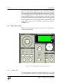
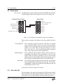
1
Operation and Service Manual
Analog Lock-In Amplifier
SR124
Stanford Research Systems
Revision 1.02 • February 3, 2014
Certification
Stanford Research Systems certifies that this product met its published specifications at the time
of shipment.
Warranty
This Stanford Research Systems product is warranted against defects in materials and workmanship for a period of one (1) year from the date of shipment.
Service
For warranty service or repair, this product must be returned to a Stanford Research Systems
authorized service facility. Contact Stanford Research Systems or an authorized representative
before returning this product for repair.
Information in this document is subject to change without notice.
c Stanford Research Systems, Inc., 2012 – 2014. All rights reserved.
Copyright Stanford Research Systems, Inc.
1290–D Reamwood Avenue
Sunnyvale, CA 94089 USA
Phone: (408) 744-9040 • Fax: (408) 744-9049
www.thinkSRS.com • e-mail: [email protected]
Printed in U.S.A.
Document number 9-01688-903
SR124
Analog Lock-In Amplifier
Contents
General Information
Safety and Preparation for Use
Symbols . . . . . . . . . . . . .
Notation . . . . . . . . . . . . .
Specifications . . . . . . . . . .
1
2
3
.
.
.
.
.
.
.
.
.
.
.
.
.
.
.
.
.
.
.
.
Getting Started
1.1 How to use this manual . . . . . .
1.2 Basic instrument check-out . . . .
1.2.1 Equipment needed . . . . .
1.3 Preparations before use . . . . . . .
1.4 Signal and input filter . . . . . . . .
1.5 Phase sensitive detector . . . . . .
1.6 Reserve . . . . . . . . . . . . . . . .
1.7 Output offset . . . . . . . . . . . . .
1.8 Reference oscillator external input
1.9 Reference oscillator output . . . . .
.
.
.
.
.
.
.
.
.
.
.
.
.
.
.
.
.
.
.
.
.
.
.
.
.
.
.
.
Introduction
2.1 Introduction to the instrument . . . .
2.1.1 Clock stopping architecture . .
2.1.2 What does the SR124 measure?
2.2 Instrument overview . . . . . . . . . .
2.2.1 Reference section . . . . . . . .
2.2.2 Signal section . . . . . . . . . .
2.2.3 Input Filter . . . . . . . . . . .
2.2.4 Output . . . . . . . . . . . . . .
2.3 Navigating the front panel . . . . . . .
2.3.1 Signal input section . . . . . . .
2.3.2 Output section . . . . . . . . .
2.3.3 Setup section . . . . . . . . . .
2.3.4 Reference section . . . . . . . .
.
.
.
.
.
.
.
.
.
.
.
.
.
.
.
.
.
.
.
.
.
.
.
.
.
.
.
.
.
.
.
.
.
.
.
.
.
.
.
.
.
.
.
.
.
.
.
.
.
.
.
.
.
.
.
.
.
.
.
.
.
.
.
.
.
.
.
.
.
.
.
.
.
.
.
.
.
.
.
.
.
.
.
.
.
.
.
.
.
.
.
.
.
.
.
.
.
.
.
.
.
.
.
.
.
.
.
.
.
.
.
.
.
.
.
.
.
.
.
.
.
.
.
.
.
.
.
.
.
.
.
.
.
.
.
.
.
.
.
.
.
.
.
.
.
.
.
.
.
.
.
.
.
.
.
.
.
.
.
.
.
.
.
.
.
.
.
.
.
.
.
.
.
.
.
.
.
.
.
.
.
.
.
.
.
.
.
.
.
v
v
vi
vii
viii
.
.
.
.
.
.
.
.
.
.
.
.
.
.
.
.
.
.
1–1
. 1–2
. 1–2
. 1–2
. 1–2
. 1–3
. 1–4
. 1–5
. 1–6
. 1–7
. 1–8
.
.
.
.
.
.
.
.
.
.
.
.
.
2–1
. 2–2
. 2–2
. 2–2
. 2–3
. 2–3
. 2–6
. 2–9
. 2 – 10
. 2 – 11
. 2 – 12
. 2 – 14
. 2 – 15
. 2 – 17
Performance Details
3–1
3.1 Sensitivity and gain . . . . . . . . . . . . . . . . . . . . 3 – 2
3.1.1 AC Gain . . . . . . . . . . . . . . . . . . . . . . 3 – 2
3.1.2 Scale normalization . . . . . . . . . . . . . . . . 3 – 3
i
ii
Contents
3.2
3.3
3.4
3.5
4
5
3.1.3 DC gain . . . . . . . . . . . .
Dynamic reserve and overloads . . .
Input filter details . . . . . . . . . . .
Attenuators and DC bias constraints
Automatic functions . . . . . . . . .
3.5.1 Auto-phase . . . . . . . . . .
3.5.2 Auto-gain . . . . . . . . . . .
3.5.3 Auto-offset . . . . . . . . . . .
3.5.4 Lock assist . . . . . . . . . . .
.
.
.
.
.
.
.
.
.
.
.
.
.
.
.
.
.
.
.
.
.
.
.
.
.
.
.
Remote Operation
4.1 Index of commands . . . . . . . . . . . . .
4.2 Alphabetic list of commands . . . . . . . .
4.3 Introduction . . . . . . . . . . . . . . . . .
4.3.1 Interface configuration . . . . . . .
4.3.2 Buffers . . . . . . . . . . . . . . . .
4.3.3 Remote / local . . . . . . . . . . . .
4.4 Commands . . . . . . . . . . . . . . . . . .
4.4.1 Command syntax . . . . . . . . . .
4.4.2 Notation . . . . . . . . . . . . . . .
4.4.3 Examples . . . . . . . . . . . . . .
4.4.4 Reference and phase commands .
4.4.5 Input commands . . . . . . . . . .
4.4.6 Filter commands . . . . . . . . . .
4.4.7 Gain and time constant commands
4.4.8 Output commands . . . . . . . . .
4.4.9 Setup commands . . . . . . . . . .
4.4.10 Auto commands . . . . . . . . . .
4.4.11 Data transfer commands . . . . . .
4.4.12 Interface commands . . . . . . . .
4.4.13 Status commands . . . . . . . . . .
4.5 Status model . . . . . . . . . . . . . . . . .
4.5.1 Status byte (SB) . . . . . . . . . . .
4.5.2 Service request enable (SRE) . . .
4.5.3 Standard event status (ESR) . . . .
Circuits
5.1 Overview of circuits
5.2 Power Supply . . . .
5.3 CPU . . . . . . . . . .
5.4 Front Panel . . . . . .
5.5 Main board . . . . . .
.
.
.
.
.
.
.
.
.
.
.
.
.
.
.
.
.
.
.
.
.
.
.
.
.
.
.
.
.
.
.
.
.
.
.
.
.
.
.
.
.
.
.
.
.
.
.
.
.
.
.
.
.
.
.
.
.
.
.
.
.
.
.
.
.
.
.
.
.
.
.
.
.
.
.
.
.
.
.
.
.
.
.
.
.
.
.
.
.
.
.
.
.
.
.
.
.
.
.
.
.
.
.
.
.
.
.
.
.
.
.
.
.
.
.
.
.
.
.
.
.
.
.
.
.
.
.
.
.
.
.
.
.
.
.
.
.
.
.
.
.
.
.
.
.
.
.
.
.
.
.
.
.
.
.
.
.
.
.
.
.
.
.
.
.
.
.
.
.
.
.
.
.
.
.
.
.
.
.
.
.
.
.
.
.
.
.
.
.
.
.
.
.
.
.
.
.
.
.
.
.
.
.
.
.
.
.
.
.
.
.
.
.
.
.
.
.
.
.
.
.
.
.
.
.
.
.
.
.
.
.
.
.
.
.
.
.
.
.
.
.
.
.
.
.
.
.
.
.
.
.
.
.
.
.
.
.
.
.
.
.
.
.
.
.
.
.
.
3–4
3–4
3–6
3–9
3–9
3–9
3 – 10
3 – 10
3 – 10
.
.
.
.
.
.
.
.
.
.
.
.
.
.
.
.
.
.
.
.
.
.
.
.
4–1
. 4–2
. 4–4
. 4–6
. 4–6
. 4–6
. 4–6
. 4–7
. 4–7
. 4–8
. 4–8
. 4–9
. 4 – 11
. 4 – 12
. 4 – 13
. 4 – 14
. 4 – 15
. 4 – 16
. 4 – 17
. 4 – 18
. 4 – 20
. 4 – 23
. 4 – 23
. 4 – 24
. 4 – 24
.
.
.
.
.
5–1
. 5–2
. 5–2
. 5–2
. 5–2
. 5–2
SR124 Analog Lock-In Amplifier
Contents
iii
5.6
5.7
5.8
5.9
SR124
Analog Lock-In Amplifier
Oscillator . . . . .
Rear outputs . . .
Communications
Schematics . . . .
.
.
.
.
.
.
.
.
.
.
.
.
.
.
.
.
.
.
.
.
.
.
.
.
.
.
.
.
.
.
.
.
.
.
.
.
.
.
.
.
.
.
.
.
.
.
.
.
.
.
.
.
.
.
.
.
.
.
.
.
.
.
.
.
.
.
.
.
.
.
.
.
.
.
.
.
.
.
.
.
.
.
.
.
5–4
5–5
5–5
5–5
iv
Contents
SR124 Analog Lock-In Amplifier
General Information
Safety and Preparation for Use
WARNING
Dangerous voltages, capable of causing injury or death, are
present in this instrument. Do not remove the product covers
or panels. Do not apply power or operate the product without
all covers and panels in place.
AC line voltage
The SR124 Analog Lock-In Amplifier operates from a 100 V, 120 V,
220 V, or 240 V nominal AC power source having a line frequency of
50 Hz or 60 Hz. Before connecting the power cord to a power source,
verify that the LINE VOLTAGE SELECTOR, located in the rear panel
power-entry module, is set so that the correct AC line voltage value
is visible.
CAUTION
The SR124 Analog Lock-In Amplifier will be damaged if operated
with the LINE VOLTAGE SELECTOR set for the wrong AC line
voltage, or if the wrong fuses are installed. Verify that the correct
line fuses are installed before connecting the line cord. Fuse size is
5MF “fast blow” (5 × 20 mm). For 100 V/120 V, use 4 A fuses; for
220 V/240 V, use 2 A fuses.
Line cord
The SR124 Analog Lock-In Amplifier has a detachable, three-wire
power cord for connection to the power source and to a protective
ground. The chassis of the instrument is connected to the outlet
ground to protect against electrical shock. Always use an outlet
which has a properly connected protective ground.
Service
The SR124 Analog Lock-In Amplifier does not have any user serviceable parts inside. Refer service to a qualified technician.
Do not install substitute parts or perform any unauthorized modifications to this instrument. Contact the factory for instructions on
how to return the instrument for authorized service and adjustment.
v
vi
General Information
Symbols you may Find on SRS Products
Symbol
Description
Alternating current
Caution - risk of electric shock
Frame or chassis terminal
Caution - refer to accompanying documents
Earth (ground) terminal
Battery
Fuse
On (supply)
Off (supply)
SR124
Analog Lock-In Amplifier
General Information
vii
Notation
The following notation will be used throughout this manual.
WARNING
A warning means that injury or death is possible if the instructions
are not obeyed.
CAUTION
A caution means that damage to the instrument or other equipment
is possible.
Typesetting conventions used in this manual are:
• Front-panel buttons are set as [Button]
• Front-panel knobs are set as Knob • Front-panel indicators are set as Overload
• Remote command names are set as *IDN?
• Literal text other than command names is set as OFF
Remote command examples will all be set in monospaced font. In
these examples, data sent by the host computer to the SR124 are set
as straight teletype font, while responses received by the host
computer from the SR124 are set as slanted teletype font.
SR124
Analog Lock-In Amplifier
viii
General Information
Specifications
All performance specifications after 1 hour warm-up at 23 ◦ C ±2 ◦ C
ambient.
Signal channel
Parameter
Voltage inputs
Sensitivity
Current input
Input impedance
Voltage
Current
Gain accurancy
Gain stability
Input noise, typ.
Input filter
Flat
Band pass
High pass
Low pass
Notch
CMRR
Dynamic reserve
Low noise
Normal
High reserve
Specification
Single-ended or differential
100 nV to 500 mV, in 1-2-5 steps
106 V/A or 108 V/A
10 MΩ + 25 pF, AC or DC coupled
100 Ω (1 kΩ) to virtual ground,
106 (108 ) V/A scale
±1% at 1 kHz
100 ppm/◦ C
(flat mode, normal reserve)
√
2.8 nV/ Hz at 1 kHz
√
0.14 pA/ Hz at 1 kHz (106 V/A)
√
0.014 pA/ Hz at 100 Hz (108 V/A)
(Tunable from 2 Hz to 100 kHz)
Flat within ±1% from 10 Hz to 20 kHz
±5% from 2 Hz to 100 kHz
Q of 1, 2, 5, 10, 20, 50, and 100
−12 dB/oct rolloff
−12 dB/oct rolloff
Up to 80 dB attenuation
90 dB below 10 kHz, DC coupled
decreasing by 6 dB/oct above 10 kHz
(without band pass filter)
20 dB
40 dB
60 dB
SR124
Analog Lock-In Amplifier
General Information
ix
Demodulator / Output
Parameter
Output gain stability
Low noise
Normal
High reserve
Output filter
Time constants
Output impedance
Specification
50 ppm/◦ C
100 ppm/◦ C
1000 ppm/◦ C
−6 dB/oct or −12 dB/oct
1 ms to 300 s in 1–3–10 steps
600 Ω
Reference channel
Parameter
Frequency range
Reference input
Minimum pulse width
Input impedance
Phase resolution
Phase accuracy
Harmonic detection
Specification
0.2 Hz to 210 kHz
TTL or sine, 100 mVrms min. f > 2 Hz,
500 mVrms min. f ≤ 2 Hz
locks to positive-going zero crossing (sine),
positive edge (TTL).
100 ns (TTL mode)
1 MΩ
AC coupled, 10 s time constant (sine)
DC coupled (TTL)
0.01◦
±5◦ (2 Hz to 20 kHz)
±10◦ (20 kHz to 210 kHz)
F, 2×F, and 3×F (ext. ref.)
Reference output
Parameter
Range
Waveform
Frequency accuracy
Frequency resolution
Amplitude range
Amplitude accuracy
Amplitude flatness
Amplitude stability
Output impedance
DC bias
SR124
Analog Lock-In Amplifier
Specification
0.2 Hz to 210 kHz
sine, square
±0.1% (20 Hz to 21 kHz)
3-1/2 digits or 1 mHz
100 nV to 10 Vrms into high-Z
±1% at 1 kHz (on 20 Hz to 2.1 kHz range)
±1% for upper decade of each range
±5% for lower decade of each range
50 ppm/◦ C, typ.
50 Ω
commandable, to ±10× amplitude,
or ±10 VDC max (amp. dependent;
see section 3.4 for details)
x
General Information
Displays and Front Panel
Parameter
Panel meter
Offset
Output
Numeric
Specification
jeweled bearing, center-zero, mirror-backed
adjustable up to ±1000 % (10×) of full scale
600 Ω output impedance,
Lock-In or AC Volt function
full static drive (no scanning refresh),
settings or one-time readings
Rear panel inputs and outputs
Parameter
VCO input
VCO output
Quadrant outputs
Preamp
Status
−Unlocked
−Overload
Remote Interfaces
RS-232
Optical fiber
Specification
10 kΩ input impedance
0 to +10 VDC for fmin to fmax of range
600 Ω output impedance, 0 to +10 VDC
600 Ω output impedance
Four 0.7 Vrms (2 Vpp) outputs, at 0◦ , 90◦ , 180◦ , 270◦
DB-9 connector to power optional
remote preamp
TTL outputs, 1 kΩ output, 10 kΩ pullup
low when reference oscillator is unlocked
low when signal chain is overloaded
DB-9, 9600 baud fixed
connection to SX199 Optical Interface
Controller, provides connectivity to
GPIB, RS-232, & Ethernet
General
Parameter
Temperature
Power
Dimensions
Weight
Fuse
Specification
0 ◦ C to 40 ◦ C, non-condensing
40 W, 100/120/220/240 VAC, 50/60 Hz
1700 W × 500 H × 1500 D
23 lbs
Type 5MF, 5 × 20 mm, “fast blow”
SR124
Analog Lock-In Amplifier
1
Getting Started
This chapter provides step-by-step instruction to get started quickly
with the SR124 Analog Lock-In Amplifier. Refer to chapter 2 for a
more complete introduction to the SR124.
In This Chapter
1.1
1.2
1.3
1.4
1.5
1.6
1.7
1.8
1.9
How to use this manual . . . . . . .
Basic instrument check-out . . . . .
1.2.1 Equipment needed . . . . . .
Preparations before use . . . . . . .
Signal and input filter . . . . . . . .
Phase sensitive detector . . . . . . .
Reserve . . . . . . . . . . . . . . . . .
Output offset . . . . . . . . . . . . .
Reference oscillator external input .
Reference oscillator output . . . . .
.
.
.
.
.
.
.
.
.
.
.
.
.
.
.
.
.
.
.
.
.
.
.
.
.
.
.
.
.
.
.
.
.
.
.
.
.
.
.
.
.
.
.
.
.
.
.
.
.
.
.
.
.
.
.
.
.
.
.
.
.
.
.
.
.
.
.
.
.
.
.
.
.
.
.
.
.
.
.
.
.
.
.
.
.
.
.
.
.
.
.
.
.
.
.
.
.
.
.
.
1–2
1–2
1–2
1–2
1–3
1–4
1–5
1–6
1–7
1–8
1–1
1–2
1.1
Getting Started
How to use this manual
Two possible starting points are available to new users of the SR124.
Those who want to begin with an overview to the functional layout
of the instrument should turn to Chapter 2.
Users who prefer to jump in and begin using the SR124 first should
continue with this Chapter, where a series of step-by-step procedures
are given to verify the basic performance of the instrument. This will
also provide a quick introduction to the SR124 and how it is operated.
Chapter 3 provides detailed discussions of the subsystems within the
SR124. Technical details, such as the actual gain allocations for each
sensitivity and reserve setting, can be found here.
Chapter 4 discusses remote operation of the SR124, over the optical
fiber or RS-232 interface.
Chapter 5 has a description of the detailed circuit schematics of the
SR124.
1.2
Basic instrument check-out
This chapter provides step-by-step instructions for verifying the basic
operation of the SR124. In addition to confirming proper operation,
it provides a good introduction to operating the lock-in.
1.2.1
Equipment needed
To perform all the steps described in this chapter, you will need:
1. a collection of several BNC cables,
2. a function generator,
3. a general purpose 2-channel oscilloscope.
1.3
Preparations before use
CAUTION
1. Before using the instrument, verify the rear-panel power entry
module is properly configured for the power line voltage in
your region. Applying power with improper setting of the
line voltage selector will result in significant damage to the
SR124.
2. Turn the rear-panel Power switch to off.
3. Plug in the AC line cord to the rear-panel power entry module,
and into a grounded wall outlet.
SR124
Analog Lock-In Amplifier
1.4
Signal and input filter
1–3
4. Connect a BNC cable from the front-panel Ref Out BNC (righthand most connector) to the A/I input of the Signal Input (lefthand most connector).
5. Switch on the AC power. Allow the unit to warm up for 1 hour
for full specified performance.
1.4
Signal and input filter
1. Restore
defaults:
Press [Recall], and then turn the
knob (large right-hand side knob) clockwise unREFERENCE til the display shows ”deFLt”. Press [Recall] a second time to
restore factory defaults.
2. Verify the panel meter shows approximately +20% (positive)
deviation.
3. Turn the SENSITIVITY knob counterclockwise 2 clicks, to select 100 mV. Verify the meter displays approximately +100%
(positive) deviation.
4. Change the filter to Notch by pressing the [Type] button four
times. The meter should swing to approximately 0% deviation.
5. Turn the Q-factor knob clockwise until Q=100. The meter
should remain near 0% deviation.
6. Press the [Mode] button
block to switch to AC
in the OUTPUT
Volt mode. Turn the SENSITIVITY knob 1 click counterclockwise, to select 50 mV. None of the overload indicators should
be illuminated.
7. Slowly (one click at a time) turn the large INPUT FILTER knob
to minimize the meter display as close to 0 (no deflection) as
possible.
8. Press the INPUT FILTER knob inward once, to illuminate the
f trim indicator.
9. Adust the frequency fine trim by turning INPUT FILTER to
mimimize the meter deflection (minimum is not very sensitive
to f trim).
10. Press the INPUT FILTER inward once more, to illuminate the
depth indicator.
11. Adjust the depth trim by turning INPUT FILTER to mimimize the meter deflection (minimum is somewhat sensitive to
depth ).
SR124
Analog Lock-In Amplifier
1–4
Getting Started
12. Turn the SENSITIVITY knob counterclockwise 2 clicks, to
10 mV. Verify the meter displays less than ±20%
deviation. Re-
peat trimming frequency and depth with the INPUT FILTER knob to minimize the meter deflection. The meter should be
less than ±10% deviation.
13. Turn SENSITIVITY 3 clicks clockwise, back to 100 mV. Press
[Mode] to return the output to Lock-In mode.
14. Press the [Type] button twice, to select Band Pass. The meter
should be near −100% deviation.
15. Perform an auto-phase adjustment by pressing the [Phase] button within the AUTO block. After a brief delay, the REFERENCE display should show near 180 deg, and the panel meter
should show +100% deviation.
16. Press the [Type] button again to select High Pass filter. The
panel meter should move near 0 deflection.
17. Perform another auto-phase adjustment by pressing [Phase] in
the AUTO block. After the pause, the phase should show a
value near 90 deg, and the meter should return to near +100%
deflection.
18. Press the [Type] button again to select Low Pass filter. The
meter should swing to near −100% deflection.
19. Perform another auto-phase adjustment by pressing [Phase] in
the AUTO block. After the pause, the phase should show a
value near 270 deg, and the meter should return to near +100%
deflection.
1.5
Phase sensitive detector
This section walks you through a demonstration of how the phase
sensitive detector (square wave mixer) operates. You will need an
oscilloscope to view the output waveforms.
A BNC cable should connect the Reference Output (Ref. Out) to the
A/I signal input. Connect the OUTPUT BNC to the oscilloscope.
1. Restore
default
settings by pressing [Recall];
turn
REFERENCE
if
necessary
to
display
”deFLt”,
and
then
press [Recall] again.
2. Change the reference
frequency from 1.000 kHz to 100 Hz by
turning the Range knob counterclockwise one click. Turn
the large REFERENCE knob counterclockwise to set the frequency to 47 Hz.
SR124
Analog Lock-In Amplifier
1.6
Reserve
1–5
3. Perform an auto-phase adjustment by pressing the [Phase] button within the AUTO block. After a brief delay, the REFERENCE display should show near 0 deg.
4. Turn the Time Constant knob counterclockwise to the min
position. Adjust the scope for 1 V per vertical division, and
around 2.5 ms per horizontal division, and adjust the trigger.
You should see a fully-rectified positive sine wave, as shown
in Figure 1.1.
Figure 1.1: Mixer waveform at 0◦ (left) and 90◦ phase shifts (right).
5. Turn the Quadrant knob one click clockwise. The signal is
now 90◦ out of phase with the reference signal, as shown in
Figure 1.1.
6. Turn the Quadrant knob one click clockwise. The signal is
now at 180◦ relative to the reference signal, as shown in Figure 1.2.
7. Turn the Quadrant knob one click clockwise. The signal is
now 270◦ out of phase with the reference signal, as shown in
Figure 1.2.
1.6
Reserve
1. Restore
default
settings by pressing [Recall];
turn
REFERENCE
if
necessary
to
display
”deFLt”,
and
then
press [Recall] again.
2. Perform an auto-phase adjustment by pressing [Phase] in the
AUTO block. After the pause, the phase should show a value
near 0 deg.
SR124
Analog Lock-In Amplifier
1–6
Getting Started
Figure 1.2: Mixer waveform at 180◦ (left) and 270◦ phase shifts (right).
3. Turn SENSITIVITY 2 clicks counterclockwise, to 100 mV. The
meter should read near +100% deflection
4. Turn Quadrant (in the Reference section) one click clockwise,
to the 90–180 interval. The meter should be near 0 deflection.
5. Turn SENSITIVITY 3 clicks counterclockwise, to 10 mV. The
meter should still read between −30% and +30% deviation,
with no overload indicators.
1 click counterclockwise, to 5 mV. The sen6. Turn SENSITIVITY sitivity OVLD indicator should light.
7. Press [Reserve] twice, to select Normal. The OVLD indicator
should
turn off.
setting (with the
Manually adjust the phase REFERENCE
knob)
to
null
the
meter.
Turn
SENSITIVITY
2
more clicks
counterclockwise,
to
1
mV.
OVLD
should
remain
off. Turn SENSITIVITY once more, to 500 µV. OVLD should
light.
8. Press [Reserve] twice again, to select High Res. OVLD should
turn off. Manually
adjust the
phase setting again to null the
meter. Turn SENSITIVITY 2 more clicks counterclockwise,
to 100 µV. You may try to further null the signal by manually
adjusting the phase setting again, although the signal may be
unstable with so much gain.
1.7
Output offset
1. Restore
default
settings by pressing [Recall];
turn
REFERENCE if necessary to display ”deFLt”, and then
press [Recall] again.
SR124
Analog Lock-In Amplifier
1.8
Reference oscillator external input
1–7
2. Press
[Ampl] in the Reference section, and turn the
REFERENCE
knob counterclockwise until the numeric display shows 95.0 mV.
3. Turn SENSITIVITY 2 clicks counterclockwise, to 100 mV. The
meter should read near +95% deflection
4. Enable the output offset by pressing [On/Off] in the OFFSET
block. Perform an auto-offset adjustment by pressing [Offset]
in the AUTO block. After the pause, the offset should show a
value near +95% offset. The panel meter should read near zero.
5. Turn SENSITIVITY 2 more clicks counterclockwise, to 20 mV.
The panel meter should still read near zero, while the REFERENCE display shows a value near +475%.
6. Turn SENSITIVITY 1 click counterclockwise, to 10 mV. The
REFERENCE display should read near +950%, and the panel
meter should still be near null.
7. Turn SENSITIVITY 1 click further counterclockwise. The display should show the message “Attn OFFSt”, and the OFFSET
annunciator in the REFERENCE display block should blink.
The sensitivity does not change.
8. Press the [Ampl] button, and reduce the amplitude to 90.0 mV.
The panel meter should show around −50% full scale deflection.
9. Press the [Offset] button in the AUTO block again, to automatically re-adjust the offset. The REFERENCE display should now
show near +900%, and the panel meter should be nulled.
1.8
Reference oscillator external input
1. Restore
default
settings by pressing [Recall];
turn
REFERENCE
if
necessary
to
display
”deFLt”,
and
then
press [Recall] again.
2. Set the function generator to produce a 1 Vrms, 2 kHz sine wave.
Connect the function generator output to the SR124 “Ext. In”
BNC, in the REFERENCE section.
3. Turn the Mode knob in the REFERENCE section one click
clockwise, to the f External setting. The Unlocked indicator
should illuminate for between 5 and 20 seconds, and then the
SR124 should lock to the external signal.
4. Press [Freq] in the REFERENCE section to perform an oscillator
frequency measurement. After a brief delay, the REFERENCE
SR124
Analog Lock-In Amplifier
1–8
Getting Started
display should show a value near 2.00 kHz.
5. Turn Mode back to Internal, and then turn it back to f External.
Immediately after turning the mode to external, press [Lock
Assist] in the AUTO section. The display should show “ASSt
Loc”, and then the SR124 should lock, displaying the external
frequency .
6. Turn Mode to 2f External, and then press [Lock Assist]. The
display should show “ASSt Loc”, and then “Err outr”, indicating the frequency is out of range for the oscillator.
7. Turn the Range knob clockwise one click to select 200–21k.
After a few seconds, the oscillator should lock. Press [Freq] to
measure the oscillator; the result should be near 4.000 kHz.
8. Turn Mode again, to 3f External, and press [Lock Assist]. The
REFERENCE display should show the result near 6.000 kHz.
1.9
Reference oscillator output
1. Restore
default
settings by pressing [Recall];
turn
REFERENCE
if
necessary
to
display
”deFLt”,
and
then
press [Recall] again.
2. Connect a BNC cable from the rear-panel Reference Output 0◦
to the Channel 1 of the oscilloscope. Trigger the scope on the
waveform, and verify a 1 kHz, 0.7 Vrms (2 V peak-to-peak) sine
wave.
3. Connect a second BNC cable from the rear-panel Reference
Output 90◦ to Channel 2 of the scope. Verify the Channel 2
signal lags Channel 1 by 90◦ .
4. Disconnect the cable from the rear-panel 90◦ output, and connect it to the 180◦ output. Verify the Channel 2 signal on the
scope appears inverted relative to Channel 1 (lagging by 180◦ ).
5. Disconnect the cable from the rear-panel 180◦ output, and connect it to the 270◦ output. Verify the Channel 2 signal on the
scope lags Channel 1 by 270◦ (leading by 90◦ ).
6. Disconnect the Channel 2 BNC from the rear-panel of the SR124,
and connect it to the front-panel Ref. Out BNC.
7. Press the [Ampl] button. Press theREFERENCEknob in
once, to select coarse, and then turn REFERENCE clockwise
until the display reads 10.00 V. Verify on the oscilloscope that
Channel 2 shows a sine wave of approximately 10 Vrms (28 V
peak to peak). The signal should be in-phase with Channel 1.
SR124
Analog Lock-In Amplifier
1.9
Reference oscillator output
1–9
8. Press [Shape] to select Square. Verify the waveform changes to
a square wave with ±10 V (20 V peak to peak).
9. Turn the REFERENCE knob counterclockwise, to reduce the
amplitude to 1.00 V on the REFERENCE display. Press [Shape]
to return to Sine output.
10. Enable the DC bias by pressing [On/Off] in the DC Bias block.
Press [Modify]
and then adjust the Bias setting
in DC Bias,
by turning REFERENCE counterclockwise, to near −2.000 V.
Verify the waveform on the scope is now shifted to an average
of −2 V.
11. Press the DC Bias [On/Off] to turn off the bias, and verify the
waveform returns to zero-centered. Press DC Bias [On/Off]
again to re-enable the −2 V DC Bias.
12. Pressthe [Ampl] button
to select Amplitude again, and then
turn REFERENCE counterclockwise until you reach the limit.
Turn the knob slow counterclockwise to reach 10.0 mV. Notice
that the SR124 will not allow the Amplitude to decrease below
10.0 mV with the DC Bias enabled and set to −2 V.
13. Press DC Bias [On/Off] to disable the Bias. With theREFERENCE focus still on Amplitude, turn REFERENCE counterclockwise to 9.99 mV. Notice the sound of the relay click.
14. Now press DC Bias [On/Off] to attempt to re-enable the Bias.
The SR124 should beep, and the AMPL annunciator will flash,
indicating the present value of Amplitude is incompatable with
(too small for) the requested (−2 V) DC Bias.
15. Press DC Bias [Modify]. The old value (−2 V) should be displayed, but the SR124 beeps in warning
that this
value is
presently unaccessable. Turn the REFERENCE knob in either direction; the displayed BIAS value will jump to −100 mV.
This is the limiting value for DC Bias when the amplitude is between 0.1 mV and 9.99 mV. Full details of the interdependence
of DC bias and Amplitude can be found in section 3.4.
SR124
Analog Lock-In Amplifier
1 – 10
Getting Started
SR124 Analog Lock-In Amplifier
2
Introduction
This chapter provides a basic overview of the SR124 Analog Lock-In
Amplifier.
In This Chapter
2.1
2.2
2.3
Introduction to the instrument . . . .
2.1.1 Clock stopping architecture . .
2.1.2 What does the SR124 measure?
Instrument overview . . . . . . . . . .
2.2.1 Reference section . . . . . . . .
2.2.2 Signal section . . . . . . . . . .
2.2.3 Input Filter . . . . . . . . . . .
2.2.4 Output . . . . . . . . . . . . . .
Navigating the front panel . . . . . .
2.3.1 Signal input section . . . . . . .
2.3.2 Output section . . . . . . . . .
2.3.3 Setup section . . . . . . . . . .
2.3.4 Reference section . . . . . . . .
.
.
.
.
.
.
.
.
.
.
.
.
.
.
.
.
.
.
.
.
.
.
.
.
.
.
.
.
.
.
.
.
.
.
.
.
.
.
.
.
.
.
.
.
.
.
.
.
.
.
.
.
.
.
.
.
.
.
.
.
.
.
.
.
.
.
.
.
.
.
.
.
.
.
.
.
.
.
.
.
.
.
.
.
.
.
.
.
.
.
.
.
.
.
.
.
.
.
.
.
.
.
.
.
.
.
.
.
.
.
.
.
.
.
.
.
.
2–2
2–2
2–2
2–3
2–3
2–6
2–9
2 – 10
2 – 11
2 – 12
2 – 14
2 – 15
2 – 17
2–1
2–2
2.1
Introduction
Introduction to the instrument
Lock-in amplifiers are used to detect and measure very small AC
signals, often in the presence of noise sources that can be orders of
magnitudes larger. Typical lock-in amplifiers today are based on
high-speed digital signal processing (DSP) techniques. This offers
outstanding performance and flexibility for many, perhaps most,
applications. For certain demanding situations, however, residual
artifacts from the DSP approach—either due to sampling lag and
real-time response, or RF clock and related noise—can fall short of
users needs.
The SR124 is a modern, all-analog lock-in amplifier that provides outstanding signal recovery capabilities, without the shortcomings that
can limit the usefulness of more common DSP-based instruments.
The design follows two basic themes. First, the signal path is entirely
built from low-noise analog electronics: the best JFETs, transistors,
op-amps, and discrete components. Second, configuration control
is managed by a microcontroller whose system clock only oscillates
during the brief moments needed to change gains or filter settings.
2.1.1
Clock stopping architecture
This “clock-stopping” architecture, first introduced by SRS in the
SR560 Voltage Preamplifier, eliminates the inconvenience and reliability issues associated with mechanical panel controls, and makes
full remote operation of the SR124 possible. Whenever the microcontroller becomes active, the CPU Activity indicator illuminates, clearly
showing when the digital clock is running. This occurs in response
to front-panel button presses or remote computer commands.
Sometimes, you need to be certain your experiment will be undisturbed: you’ve cooled your sample to a few millikelvin, all your
wiring is still intact, and the best device you’ve built all year is ready
for measurement. A locking toggle switch on the front panel can be
set to “INHIBIT”, forcing the digital clock to remain off, even if you
press other buttons or knobs. The analog configuration of the SR124
stays steady, letting you run for minutes, hours, days—as long as
you need.
2.1.2
What does the SR124 measure?
In lock-in mode, the SR124 multiplies the input signal by a square
wave at the reference frequency, using a square-wave analog mixer.
The resulting signal is then low-pass filtered to produce an output
proportional to the frequency component of the user’s input signal at
the reference frequency (and also, to a diminishing extent, at it’s odd
SR124
Analog Lock-In Amplifier
2.2
Instrument overview
2–3
harmonics). This process is also known as phase-sensitive detection,
and the square-wave mixer is also referred to as the phase-sensitive
detector (PSD) or the synchronous detector.
A separate AC Volt mode allows the square-wave mixer to be controlled by the signal polarity of the input signal itself, essentially converting the SR124 into an absolute-value averaging measurement.
When a phase reference signal is not available, the AC Volt mode
(together with the input filter) can be used to recover specific AC signals as well, although the lock-in mode will almost always produce
superior results when a reference is available.
The final measured value is displayed on the jeweled panel meter,
and output as a proportional DC voltage. Full-scale sensitivity is
set from the front panel in 1 – 2 – 5 steps from 100 nV to 500 mV. A
full scale input in-phase with the reference will generate +10 V at the
output BNC, while a full scale signal 180◦ out of phase will generate
−10 V. Lock-in amplifiers as a general rule display the input signal
in volts RMS, and this is the basis for the SR124 calibration as well.
For example, if the SR124 is configured for 2 mV sensitivity and a
1 mVrms sine wave is input, at the reference frequency, then the BNC
output will read +5 V and the panel meter will show 50% positive
deflection.
2.2
Instrument overview
An overview of the SR124 with its main sections is given below.
Further details of each block are in chapter 3. A block diagram of
the SR124 is given in Figure 2.1.
2.2.1
Reference section
Operating in Lock-In mode, the SR124 requires the reference oscillator to control the frequency and phase of the square-wave mixer.
The analog reference oscillator of the SR124 generates a stable sine
wave with outputs at 0◦ , 90◦ , 180◦ , and 270◦ (all four outputs can
be monitored from rear panel BNC connectors). The oscillator is
based on an analog voltage-controlled oscillator (VCO) that can tune
across a factor of 100 in frequency; 5 overlapping frequency ranges
are available for operation from 0.2 Hz – 21 Hz, up to 2 kHz – 210 kHz.
The oscillator is controlled in one of three ways: internal, rear-panel
VCO, and external reference. When the SR124 operates in AC Volt
mode, the reference oscillator is available for excitation outputs, but
is not routed to the PSD.
SR124
Analog Lock-In Amplifier
2–4
Introduction
SIGNAL
MONITOR
A/I
B
+
–
A–B
DC GAIN
+
×10
–
INPUT
FILTER
A
FLOAT
PSD
AC GAIN
PREAMP
600 Ω
TIME
CONSTANT
OUTPUT
600 Ω
AC VOLT
LOCK-IN
INTERNAL
REAR VCO
OFFSET
PHASE
SHIFT
SQUARE
VCO
90°
0°
+
×1
–
REF
ATTEN
REF OUT
50 Ω
EXT. IN
DC
BIAS
PLL
Figure 2.1: The SR124 block diagram.
2.2.1.1
Internal mode
Operating in Internal mode, the SR124 oscillator is programmed by
an internally-generated DC voltage
source. Within the oscillator
frequency range (set by the Range knob), the oscillator frequency is
controlled with the front-panel control knob or remote command.
2.2.1.2
Rear-panel VCO mode
When configured for Rear VCO operation, the SR124 oscillator programming voltage is directly controlled by the user through a rearpanel BNC input. Input voltage from 0 to +10 V will set the oscillator
frequency between the lower and upper limits set by the range, with
an approximately linear transfer function.
2.2.1.3
External mode
The SR124 oscillator can lock to an external reference signal applied
to the Ext. In BNC connector. This input operates in two distinct
modes, sine input and TTL input (indicated by the TTL indicator
just above the connector).
SR124
Analog Lock-In Amplifier
2.2
Instrument overview
2–5
In sine mode, this input is AC coupled above 0.016 Hz (10 s time constant), and has an (AC) input impedance of 1 MΩ. A sine wave input
greater than 100 mVrms for frequencies above 2 Hz (500 mV below
2 Hz) will trigger the input discriminator. Positive zero crossings are
detected and considered to be the zero for the reference phase shift.
Note that, because the input is AC coupled, the discriminator circuit
actually triggers when the input signal crosses the DC average input
value in the positive direction.
When a user has a square wave or other TTL-like signals, the Ext. In
should be operated in TTL mode. In this configuration, the input is
DC coupled, and the input discriminator triggers on positive edges as
they cross +1 V. In TTL mode, there is no restriction on the reference
input duty factor, so long as the input pulses are at least 100 ns wide.
Operating in external mode, the user can select between locking to
the fundamental of the input frequency, or either of the first two harmonics. Locking to 2f External will cause the reference oscillator to
function at twice the external input frequency; locking to 3f External
will similarly cause the reference oscillator to operate at three times
the external input frequency. Note that, for harmonic operation, the
Range setting must correspond to the final frequency for the reference oscillator, which might not include the user’s external input
frequency.
2.2.1.4
Reference output
The SR124 reference oscillator drives the front-panel Ref. Out BNC
signal. This output can be configured as either sine wave or square
wave. The amplitude of the reference output can be set from 10 V
to 100 nVrms; at several points passive resistive attenuators are
switched in to reduce the signal amplitude while keeping a high
signal-to-noise ratio on the Ref. Out signal.
The Ref. Out signal can also be DC biased, allowing users to more
easily perform experiments such as differential conductance measurements without additional instrumentation. When enabled, the
DC Bias is added to the reference oscillator output; the range of DC
Bias is dependent on the reference amplitude, as the Bias and AC both
are routed through the same resistive attenuators. See section 3.4 for
the detailed interdependence of DC Bias and reference amplitude.
The rear panel Reference Output monitors are not shifted by the DC
Bias setting, and they are not attenuated by the amplitude setting;
these 4 “quadrant” monitors provide 1 V outputs for auxiliary use.
SR124
Analog Lock-In Amplifier
2–6
2.2.1.5
Introduction
Phase shift
A commandable phase shift, between 0◦ and 360◦ , is applied between
the reference oscillator and the phase-sensitive detector. This phase
shift determines the phase at which the lock-in will respond. If the
Ref. Out signal is directly connected to the Signal Input (A), and the
phase is set to 90◦ , the output will be near zero; setting the phase to
180◦ will result in a negative output signal.
2.2.2
Signal section
The SR124 Signal section provides the amplification and signal conditioning of the analog signal that is applied to the phase sensitive
detector. Inputs can be either voltage or current, and single-ended
or differential.
2.2.2.1
Voltage preamplifier
The SR124 front-end signal input stage consists of a JFET-based lownoise differential voltage preamplifier. Inputs can be configured as
either single-ended (A) or differential (A–B). To preserve the low
noise performance of the input JFET’s, this front-end input stage amplifies the input by a gain of 50× (5× for the largest scale sensitivities).
In single-ended operation, the SR124 internally measures the signal
as a voltage on the center pin of the A input, referenced to internal
ground in the instrument. This is indicated as A on the front panel.
In fully differential operation, the preamplifier measures the voltage difference between the center pins of the A and B inputs. This
configuration is indicated as A–B on the front panel.
When using differential input mode, it is important that both input
cables travel the same path between the experiment and the lock-in.
Specifically, there should not be a large loop area enclosed by the two
cables. Such loops are susceptible to magnetic pickup. Ideally, the
two coax cables are equal length and fastened to each other along
their length.
When used with an SRS external preamp, such as any model from
the SR55x series, the SR124 should always be configured for A–B
input, and two equal-length BNC cables should be used to connect
the preamp output to the lock-in signal input.
2.2.2.2
Current preamplifier
The current input on the SR124 uses the A input BNC. Two internal
gain settings are available: 106 Volts/Amp and 108 Volts/Amp. The
current input is always DC coupled and includes an input (burden)
SR124
Analog Lock-In Amplifier
2.2
Instrument overview
2–7
resistor of 100 Ω (106 range) or 1 kΩ (108 range). The maximum fullscale input signal is 500 nA (106 range) or 5 nA (108 range). Selecting
AC input coupling will block the DC output of the current amplifier
before it is further amplified by the voltage preamplifier.
Current (transimpedance) amplifiers can be susceptible to noise
peaking or oscillation when driven with excessive input capacitance.
Cable capacitance in particular should be minimized when using the
current amplifier by selecting the shortest cables practical. The SR124
current inputs will remain stable for total input capacitances below
12 nF. Note, however, that external input capacitance will increase
the voltage noise gain of the current amplifier; input capacitance
should always be minimized for best performance.
The overall sensitivity of the SR124 in current mode is dependent on
the Sensitivity setting. The current preamplifier itself converts the
input current signal to a low-level voltage with the specified transimpedance gain (106 or 108 ); the resulting voltage signal is then
amplified by the entire signal chain including the voltage preamplifier. The overall full-scale sensitivity is determined by dividing the
Sensitivity setting by the current gain. For example, if the Sensitivity
is set to 20 mV and the input is configured as 108 V/A, the full-scale
sensitivity will be 200 fA (20 mV / 108 V/A).
In most cases, there is little noise improvement for current inputs
by selecting dynamic reserve of Low Noise. The greatest stability is
achieved with High Res.
2.2.2.3
Grounding
To minimize noise pick-up, it is important to ground the outer shield
of the input cable(s). Grounding the input cable at both ends, however, can in some situations introduce unwanted ground loops to the
experiment. This has the potential to allow stray magnetic flux to induce ground currents to flow through the shield, creating additional
noise and potentially upsetting sensitive measurements.
To help users better manage grounding, the SR124 provides control
of the local grounding of the input BNC shields. When set to Ground,
the shields on the A and B input connectors are electrically tied to
the SR124 ground. When set to Float, however, a 10 kΩ resistor is
added in series between the connector shells and instrument ground.
This 10 kΩ resistor is large enough to block flux-generated ground
currents, while still preventing stray charge from accumulating on
the connector shell. If the user’s signal source already provides
a good, low-impedance connection between the signal shield and
ground, then selecting Float may eliminate potential ground-loop
problems.
SR124
Analog Lock-In Amplifier
2–8
2.2.2.4
Introduction
AC versus DC coupling
The signal input can be AC or DC coupled. The AC coupling high
pass filter passes signals above 160 mHz and attenuates signals at
lower frequencies. Internal gain stages within the signal path are
always AC coupled, so any user DC offset will not affect the results
at the phase-sensitive detector output (where they would otherwise
generate a “1 × f” ripple at the output). However, if the input signal
has a significant DC offset relative to the AC amplitude, then AC
coupling will significantly improve the overall dynamic reserve by
blocking the DC input before it could saturate the preamplifier.
When operating in differential mode (A–B), AC coupling may reduce
the SR124’s effective common-mode rejection and gain accuracy, as
the blocking capacitors for the AC coupling are only matched to
5% tolerance. This effect is most pronounced at frequencies below
10 kHz.
2.2.2.5
Dynamic reserve
The total signal gain for the SR124 is distributed between the AC
signal path ahead of the PSD, and the DC signal path following the
PSD. The product of all gains, AC and DC, combine to provide the
selected full-scale Sensitivity. How this allocation is made between
AC and DC gain determines the dynamic reserve of the lock-in.
Dynamic reserve is traditionally defined as the ratio of the largest
interfering signal that can be tolerated, to the full scale input signal,
expressed in dB. For example, if the SR124 is operating at full scale
sensitivity of 1 µV, and an interfering signal of up to 1 mV can be
rejected before overloading, the dynamic reserve is 60 dB.
Many of the noise advantages of a lock-in amplifier come from the
improved noise and stability properties of electronics operating at AC
frequencies compared to DC. Overall total gain is determined by the
full-scale sensitivity, but the relative allocation of that gain between
the AC and DC portions of the instrument rely on a “policy” decision
that the user can influence using the Reserve setting.
For the lowest noise and greatest output stability, set the Reserve
mode to Low Noise. This will allocate the maximum gain to the AC
portion of the signal path, and apply the minimum DC gain needed
for the final sensitivity. This configuration minimizes the impact of
offsets and drift from the DC circuitry, but also tends to reduce the
dynamic reserve since more of the signal gain is applied to the AC
path, before the PSD can act to select the signal of interest.
For the greatest dynamic reserve, set the Reserve mode to High Res.
This will allocate the maximum gain to the DC portion of the signal
SR124
Analog Lock-In Amplifier
2.2
Instrument overview
2–9
path, and apply the minimum AC gain needed for the final sensitivity. This configuration will have worse offset and drift behavior
compared with Low Noise, since the DC gain stages are providing
more of the overall total gain. However, larger interfering signals
can be tolerated without overloading the AC circuits, and the PSD
will then tend to greatly suppress that interference.
Between these two settings, a compromise Normal mode is also
available, which provides more DC gain than the Low Noise setting,
but less than the High Reserve setting.
See section 3.2 for more details about the exact gain allocations and
overload limits for these three modes.
2.2.3
Input Filter
The phase-sensitive detector is the primary feature for optimizing
recovery of small signals in the presence of noise. However, the
programmable input filter can be a helpful supplement in optimizing
the SR124’s performance. In applications with significant noise or
other interference, the magnitude of the interfering signals can limit
the total amount of AC gain that can be used before the mixer. The
input filter is available to suppress those interfering signals, allowing
greater AC gain to be used for better low-level signal recovery.
The input filter is located in the AC signal path, between the preamplifier and the programmable AC gain stage. The input filter’s function can be selected as Low Pass, High Pass, Band Pass, or Notch
filter. The filter can also be bypassed by selecting Flat. The filter
is realized as a two-pole state variable circuit, allowing fine control
of the filter tuning parameters. The input filter is typically used to
either selectively pass a frequency range that spans the input signal,
or to selectively reject one or more interfering signals at frequencies removed from the signal; these two approaches are sometimes
indistinguishable.
The filter also has a user-configurable “Q” setting, which controls the
relative width of the filter’s frequency response. In band pass and
notch settings, higher Q settings provide a narrower filter response,
allowing more selective frequency selection; lower Q settings wider
filters, with broader frequency selection. Note that for the low pass
and high pass settings, the filter gain is calibrated for unity gain at
the peak response—the response across the pass band far from the
peak response attenuates the signal by a factor of 1/Q. See section 3.3
for the detailed filter transfer functions of the SR124 input filter.
SR124
Analog Lock-In Amplifier
2 – 10
2.2.4
Introduction
Output
The DC portion of the SR124, beginning with the output of the phasesensitive detector, is collectively referred to as the output section.
2.2.4.1
Output filter
The output of the phase sensitive detector contains many signals.
Most of the output signals are at the sum or difference frequency
between an input signal frequency and the reference frequency. Only
the component of the input signal whose frequency is exactly equal
to the reference frequency will result in a DC output. To remove all
the unwanted AC signals, both the “2 × f” (sum of the signal and
reference) as well as the noise components, a configurable low-pass
filter is used.
The output low pass filter follows the mixer, and comes before the
final output DC gain is applied. This filter is key to the performance
of the lock-in amplifier, as it selects the DC output of the mixer while
rejecting the high frequency ripple artifacts naturally generated by
the mixing process. The filter can be configured as either 1 pole or 2
poles, with a time constant between 1 ms and 300 s settable in 1–3–10
steps.
The time constant is related to the −3 dB frequency of the filter by the
relation f-3dB = 1/(2πTC), where TC is the time constant in seconds.
The low pass filters are simple 6 dB/octave roll off, RC-type filters. A
1 second time constant refers to a filter whose -3 dB point occurs at
0.16 Hz. In the SR124 the user can select one or two successive stages
of output filter, so that the overall filter can roll off is either 6 dB or
12 dB per octave. The time constant refers to the −3 dB point of each
filter stage alone (and not the combined filter).
The time constant also determines the equivalent noise bandwidth
(ENBW) for the measurement. The ENBW is not the filter −3 dB
bandwidth; rather it is the effective bandwidth for Gaussian distributed white noise. When set to 6 dB/octave, the ENBW is 1/(4×TC);
when set to 12 dB/octave, ENBW = 1/(8 × TC).
It can be useful to consider the frequency domain, in which the
output filter defines the width of the passband for detection at the
reference frequency. By mixing with the lock-in amplifier, this AC
band is mixed down to DC for final output. The −3 dB bandwidth
for signal selection at the input is simply 1/(2π × TC). To effectively
reject the mixer AC artifacts, the output filter should be set so that
TC > (2 – 10) × (1/f), where f is the reference oscillator frequency.
SR124
Analog Lock-In Amplifier
2.3
Navigating the front panel
2.2.4.2
2 – 11
AC Volt mode
When phase-sensitive detection is not possible, the SR124 can be
configured for AC Volt mode. In this setting, the reference oscillator
is unused and the phase-sensitive detector (square wave mixer) is
controlled directly by the polarity of the amplified AC input signal.
The instrument now acts as an averaging AC voltmeter, where the
detection element is an absolute value detector.
For most applications using AC Volt mode, the Reserve setting
should be set to Low Noise, since there is no reserve benefit from
the mixer in this configuration. If the input signal is not already relatively clean with high signal-to-noise, the input filter may be used
to define the frequency band for measurement.
2.3
Navigating the front panel
The front panel of the SR124 is organized into distinct functional
sections. Knowing this organization will help you to become familiar
with its operation. A diagram of the entire front panel is in Figure 2.2,
below.
Stanford Research Systems
SENSITIVITY
OVLD
µV
50
100 200 500
5
10
10
5
knob
2
50
100
500
200
100
500
200
10
5
SIGNAL INPUT
Input
knob
Save
AC
DC
Float
Ground
Ground
B
BNC
BNC
10 MΩ
10 MΩ
Recall
100
CONTROL INHIBIT
OVLD
Couple
A/I
1
Q-factor
Band Pass
High Pass
Low Pass
Notch
Flat
Type
RESERVE
High Res.
Normal
Low Noise
Reserve
Signal
Monitor
OVLD
6 dB/oct.
12 dB/oct.
ms
30
100 300
1
OUTPUT
Lock-In
AC Volt
s
30
3
OFFSET
On
3
10
10
Slope
On/Off
PHASE
FREQ
AMPL
BIAS
%
coarse
fine
OFFSET
Push to select
knob
BNC
Time Constant
270
180
90
0
360
270
180
90
Hold to
null
All digital clocks and
panel controls disabled
during lockout
switch
BNC
600 Ω
CPU Activity
Remote Activity
Internal
Rear VCO
Ext. In
TTL
Unlocked
BNC
Ampl
Freq
Mode
3f
2f External
f
knob
300
Modify
Phase
INHIBITED
Mode
100
1
min
600 Ω
mV
deg
Quadrant
local
OUTPUT
knob
50
V
Hz
REFERENCE
SETUP
Hold to
null
20
kHz
Lock
Assist
REM
Push to select
INPUT FILTER
2
A
A–B
6
I (10 )
I (108)
Offset
f trim
depth
20 mV
1
nV
Gain
Phase
Hz
2
20
Model SR124 Analog Lock-In Amplifier
AUTO
OVLD
kHz
1
Push for
Ext. In TTL
knob
210k
21k
2.1k
210
21
DC Bias
On
Range (Hz)
2.0k
200
20
2.0
0.2
knob
knob
Ref. Out
Square
Sine
On/Off
Shape
Modify
BNC
50 Ω
Figure 2.2: The SR124 front panel.
In Figure 2.2, the two large rectangular blocks above “INPUT FILTER” and “REFERENCE” are static numeric displays. The larger
white rectangle in the upper center of the drawing is the jewel bearing analog panel meter.
The two large knobs each have a push-button secondary function;
in addition to adjusting the parameter currently “in focus” (more
about that later), briefly pressing the knob inward has a secondary
function. Also, holding the knob in for several seconds has a tertiary
function—clearing or nulling the parameter in focus.
SR124
Analog Lock-In Amplifier
2 – 12
Introduction
Near the center of the instrument, in the “CONTROL INHIBIT”
block, is a large locking toggle switch. When in the upper position,
none of the front-panel (or remote) interface functions are operable.
The analog signal processing of the SR124 remains fully functioning
while the Inhibit switch is up, but no controls will respond. For normal operation, the Inhibit switch should be left in the lower position.
Where applicable, the corresponding remote command is listed,
along with the page where it is defined, in parentheses, like this:
(FORM, 4 – 11 ).
2.3.1
Signal input section
The left-hand section of the instrument comprises the “Signal Input”.
See Figure 2.3 for detail.
Stanford Research Systems
SENSITIVITY
OVLD
µV
50
100 200 500
kHz
1
Hz
2
20
5
10
10
5
knob
2
1
50
100
500
200
nV
100
f trim
depth
20 mV
500
200
10
5
A
A–B
6
I (10 )
I (108)
Input
1
Hold to
null
20
knob
50
2
SIGNAL INPUT
Push to select
INPUT FILTER
knob
100
OVLD
AC
DC
Couple
Float
Ground
Ground
A/I
B
BNC
BNC
10 MΩ
10 MΩ
Q-factor
Band Pass
High Pass
Low Pass
Notch
Flat
Type
RESERVE
High Res.
Normal
Low Noise
Signal
Monitor
Reserve
BNC
600 Ω
Figure 2.3: The SR124 front panel signal input section.
2.3.1.1
Signal input
User input signals are applied to the SR124 through the “A/I”, or the
“A/I” and “B” BNC connectors. The input configuration is controlled
SR124
Analog Lock-In Amplifier
2.3
Navigating the front panel
2 – 13
by the [Input] button. Each successive press of [Input] steps from A,
to A–B, to I (106 ), to I (108 ), and then back to A. (ISRC, 4 – 11 )
Input coupling can be switched between AC and DC by pressing
[Couple]. (ICPL, 4 – 12 )
The outer (shield) terminal of both input BNCs are tied to each other
and can be set to Float (through 10 kΩ) or Ground (through 10 Ω) by
pressing [Ground]. (IGND, 4 – 12 )
Overloads at the preamplifier stage are indicated by the red OVLD
indicator in the signal input block.
2.3.1.2
Sensitivity
The overall gain of the SR124 is controlled by setting the sensitivity.
Full scale sensitivities from
100 nV to 500
mV, in 1–2–5 steps, can be
selected by turning the SENSITIVITY knob. (SENS, 4 – 13 )
Overloads in the AC signal path, after the preamplifier but before the
phase sensitive detector, are indicated by the red OVLD indicator in
the sensitivity block.
2.3.1.3
Input filter
The input filter type is selected by pressing [Type]; selections cycle
from Band Pass, High Pass, Low Pass, Notch, and Flat. (TYPF, 4 –
12 )
The
Q-factor can be adjusted between 1 and 100 by turning the
filter Q-factor knob. (QFCT, 4 – 12 )
The
of the filter is adjusted by turning the large
tuning frequency
knob. This knob responds with velocity sensitivity,
INPUT FILTER so turning the knob more quickly will span larger frequency ranges
quickly. The frequency setting is displayed on the numeric display,
with either Hz or kHz illuminated. (IFFR, 4 – 12 )
When operating the input filter as Band Pass or Notch type, and at
high Q-factor,
it is often necessary
to trim the input filter performance.
Pressing INPUT FILTER cycles the knob’s focus between the main
frequency tune, a (dimensionless) trim offset of the frequency (f trim),
and a notch depth adjust (depth ). When adjusting f trim or depth,
the units annunciators (Hz and kHz) are both off. (IFTR, 4 – 12 )
2.3.1.4
Reserve
The dynamic reserve setting of the SR124 can be cycled between High
Res., Normal, and Low Noise by successive presses of [Reserve].
SR124
Analog Lock-In Amplifier
2 – 14
Introduction
(RMOD, 4 – 13 )
The output of the entire AC signal chain, just prior to the phase
sensitive detector, can be monitored from the “Signal Monitor” BNC.
2.3.2
Output section
The next section of the instrument is “Output”. See Figure 2.4 for
detail.
OVLD
OUTPUT
OVLD
6dB/oct.
12dB/oct.
ms
30
100 300
1
Slope
s
30
3
On/Off
Mode
Modify
BNC
100
1
min
On
3
10
10
OUTPUT
Lock-In
AC Volt
OFFSET
knob
300
Time Constant
600 Ω
Figure 2.4: The SR124 front panel output section.
The panel meter shows the output signal from the SR124. This is the
same signal as appears at the output BNC. The meter shows +100%
deflection when the BNC output is +10 V, and −100% deflection when
the BNC output is −10 V.
If any part of the signal path is overloaded, the master OVLD annunciator, at the upper right of the panel meter, is lit.
2.3.2.1
Time constant
The output filter time constant is set with the Time Constant knob.
(OFLT, 4 – 14 )
SR124
Analog Lock-In Amplifier
2.3
Navigating the front panel
2 – 15
The choice of one or two poles of output filter is toggled by pressing
[Slope]. (OFSL, 4 – 14 )
If the DC output signal is overloaded, the red OVLD indicator (just
above the time constant control) is lit.
2.3.2.2
Offset
The output offset function is enabled and disabled by pressing the
[On/Off] button within the OFFSET block. (OFSE, 4 – 14 )
Pressing [Modify] within the OFFSET block switches the
focus of the
REFERENCE block to the offset value; turning the REFERENCE knob will then adjust the offset between −1000% and +1000% of full
scale. (OFST, 4 – 15 )
2.3.2.3
Output
The overall functional mode of the SR124 is controlled by the [Mode]
button within the OUTPUT block. Pressing [Mode] toggles between
Lock-In and AC Volt modes. (OMOD, 4 – 14 )
The output signal from the SR124 is available on the BNC output
connector within the OUTPUT block. Full scale at the output is
±10 V.
2.3.3
Setup section
The next section of the instrument is “Setup”. See Figure 2.5 for
detail.
2.3.3.1
Automatic functions
Four built-in automatic functions are available in this block.
Pressing [Phase] within AUTO starts an auto-phase cycle, which
adjusts the oscillator phase to maximize the output signal. Autophase is disabled when output offset is enabled. (APHS, 4 – 16 )
Pressing [Gain] starts an auto-gain cycle, which will increase the gain
(decrease the sensitivity) step by step to maximize the output without
causing a signal overload. (AGAN, 4 – 16 )
Pressing [Offset] starts an auto-offset cycle, which will adjust the
OFFSET setting to null the output signal. Note that the auto-offset
cycle does not change the enabled/disabled state for OFFSET. Running auto-offset with offset disabled will set and report the offset
parameter that would null the output if offset were enabled, but the
output is unaffected. (AOFF, 4 – 16 )
SR124
Analog Lock-In Amplifier
2 – 16
Introduction
AUTO
Phase
Gain
Offset
Lock
Assist
SETUP
local
Save
Recall
CONTROL INHIBIT
INHIBITED
All digital clocks and
panel controls disabled
during lockout
switch
CPU Activity
Remote Activity
Figure 2.5: The SR124 front panel setup.
Pressing [Lock Assist] starts a measurement cycle for the Reference
oscillator Ext. In, to speed the locking to a user’s reference when
operating in external mode. (ASST, 4 – 17 )
2.3.3.2
Setup
A total of nine (9) separate user configurations can be
saved in the
SR124. Pressing [Save] shifts the focus to saving; the REFERENCE knob now scrolls between 0-8 to select one of the nine user slots.
Pressing [Save] a second time saves the current instrument configuration into that slot; pressing any other key abandons the save
request. (SSET, 4 – 15 )
The [Recall] key is used to restore a previously saved configuration.
Press [Recall]
once to bring up the recall focus, and then turn
REFERENCE to select between user setting 0 through 8. An additional
configuration,
the factory defaults, can be restored by turning
REFERENCE to display “dEFLt”. When the desired settings slot is
displayed, press [Recall] again to restore those settings. Pressing any
other key will abandon the recall request. (RSET, 4 – 15 )
When the SR124 is in REM mode (remote control), pressing the [ReSR124
Analog Lock-In Amplifier
2.3
Navigating the front panel
2 – 17
call] button asserts the “Local” function and returns the instrument
to local mode. (LOCL, 4 – 19 )
2.3.3.3
Control inhibit
The SR124 user interface controls can be inhibited by setting the
control inhibit switch to the upper position. Note that this is a locking
toggle switch, and must be gently pulled outwards while switching
upwards or downwards.
When in the upper position, the INHIBITED indicator is illuminated
to alert the user that controls and remote commanding are all inhibited.
2.3.4
Reference section
The next section of the instrument is “Reference”. See Figure 2.6 for
detail.
Model SR124 Analog Lock-In Amplifier
REM
PHASE
FREQ
AMPL
BIAS
kHz
V
Hz
mV
deg
%
coarse
fine
OFFSET
REFERENCE
Push to select
Hold to
null
Quadrant
270
180
90
0
360
270
180
90
Phase
Mode
Push for
3f
Ext. In TTL
2f External
f
knob
Internal
Rear VCO
Ext. In
TTL
Unlocked
BNC
Ampl
Freq
knob
210k
21k
2.1k
210
21
DC Bias
Ref. Out
Square
Sine
On
Range (Hz)
2.0k
200
20
2.0
0.2
knob
knob
On/Off
Shape
Modify
BNC
50 Ω
Figure 2.6: The SR124 front panel reference.
The numeric display for the Reference section can show the settings
for phase, reference oscillator frequency, amplitude, DC bias, output offset, and also the save/recall slot. This selection is generally
SR124
Analog Lock-In Amplifier
2 – 18
Introduction
called the “focus” of the interface, and is indicated by one of the
text annunciators at the bottom of the numeric display.
For most
of the parameters, turning the large REFERENCE knob allows that
parameter to be adjusted.
knob inward toggles between coarse and
Pressing the REFERENCE fine scrolling speeds for adjusting parameters. Holding the knob in
for approximately 2 seconds will cause the parameter to be nulled
(other than frequency and amplitude, which do not allow zero settings).
Within the REFERENCE section, pressing [Phase] brings the reference phase shift into focus. Note that in AC Volt mode, phase is
unused (but may still be adjusted). (PHAS, 4 – 9 )
Pressing [Freq] brings frequency into focus. When operating in Internal mode, frequency can be adjusted across the 2 decades range
selected by the Range block. (FREQ, 4 – 9 )
Pressing [Freq] when operating either in Rear VCO mode or one of
the External modes causes the SR124 to perform a frequency measurement on the actual reference oscillator frequency. That frequency
is then displayed on the numeric display.
If the focus is already on FREQ when the instrument changes mode
into either Rear VCO or External, the display will show “- - - - ”; pressing [Freq] again will cause a frequency measurement to be
performed and displayed. Each successive press of [Freq] initiates a
new measurement.
Pressing [Ampl] brings the reference output amplitude into focus.
Turning REFERENCE adjusts the output amplitude (in Vrms).
(SLVL, 4 – 10 )
2.3.4.1
Quadrant
Turning the Quadrant knob adds or subtracts 90◦ from the current
value of the reference phase shift. One of the four quadrant indicators
is always illuminated to show which quadrant the current value of
phase lies in. (QUAD, 4 – 9 )
2.3.4.2
Ext. In
The Ext. In BNC input is used for locking the SR124 to an external
reference; this input is unused when in Internal or Rear VCO mode.
The Ext. In circuit can be configured for either sine inputs or TTL
inputs; when in TTL mode, the TTL indicator is illuminated in this
section.
user can toggle between sine and TTL mode by pressing
The
the Mode knob (see below).
SR124
Analog Lock-In Amplifier
2.3
Navigating the front panel
2.3.4.3
2 – 19
Mode
The Mode knob selects the reference oscillator mode. Possible selections are Rear VCO, Internal, f External, 2f External, and 3f External.
(FMOD, 4 – 9 )
The Mode knob also controls
Ext. In configuration between sine
the and TTL modes. Pressing Mode inwards toggles between the two
states, as indicated by the TTL indicator in the Ext. In sub-section.
(RSLP, 4 – 10 )
2.3.4.4
Range
The Range knob selects the reference oscillator frequency range.
Ranges each span 2 decades, and overlap by one decade each.
(FRNG, 4 – 10 )
2.3.4.5
DC Bias
Pressing the [On/Off] button in the DC Bias block toggles the bias on
and off for the reference output signal. (BION, 4 – 11 )
Depending on the current value of the reference amplitude and bias,
the bias might not be allowed to turn on. Full details of the interdependence of DC Bias and amplitude can be found in section 3.4.
Pressing the [Modify] button within DC Bias brings the
display focus
to BIAS. The bias setting can be adjusted by turning REFERENCE ;
however, the bias will not be added to the reference output unless it
is enabled with the [On/Off] button. (BIAS, 4 – 11 )
2.3.4.6
Ref. Out
The Ref. Out BNC connector provides the refence output signal. The
RMS amplitude of the signal is adjusted with the AMPL parameter.
Pressing [Shape] toggles between sine output and square output.
(FORM, 4 – 11 )
SR124
Analog Lock-In Amplifier
2 – 20
Introduction
SR124 Analog Lock-In Amplifier
3
Performance Details
This chapter provides a detailed discussion of the operating characteristics and architecture of the SR124.
In This Chapter
3.1
3.2
3.3
3.4
3.5
Sensitivity and gain . . . . . . . . . .
3.1.1 AC Gain . . . . . . . . . . . . .
3.1.2 Scale normalization . . . . . . .
3.1.3 DC gain . . . . . . . . . . . . .
Dynamic reserve and overloads . . .
Input filter details . . . . . . . . . . .
Attenuators and DC bias constraints
Automatic functions . . . . . . . . . .
3.5.1 Auto-phase . . . . . . . . . . .
3.5.2 Auto-gain . . . . . . . . . . . .
3.5.3 Auto-offset . . . . . . . . . . . .
3.5.4 Lock assist . . . . . . . . . . . .
.
.
.
.
.
.
.
.
.
.
.
.
.
.
.
.
.
.
.
.
.
.
.
.
.
.
.
.
.
.
.
.
.
.
.
.
.
.
.
.
.
.
.
.
.
.
.
.
.
.
.
.
.
.
.
.
.
.
.
.
.
.
.
.
.
.
.
.
.
.
.
.
.
.
.
.
.
.
.
.
.
.
.
.
.
.
.
.
.
.
.
.
.
.
.
.
.
.
.
.
.
.
.
.
.
.
.
.
3–2
3–2
3–3
3–4
3–4
3–6
3–9
3–9
3–9
3 – 10
3 – 10
3 – 10
3–1
3–2
3.1
Performance Details
Sensitivity and gain
While not necessary to operate the SR124, many users will still find
detailed information about gain allocation helpful for optimizing
measurements.
3.1.1
AC Gain
Table 3.1: AC gain allocation
High Res.
100 nV
200 nV
500 nV
1 µV
2 µV
5 µV
10 µV
20 µV
50 µV
100 µV
200 µV
500 µV
1 mV
2 mV
5 mV
10 mV
20 mV
50 mV
100 mV
200 mV
500 mV
Sensitivity
Normal Low Noise
100 nV
200 nV
500 nV
100 nV
1 µV
200 nV
2 µV
500 nV
5 µV
1 µV
10 µV
2 µV
20 µV
5 µV
50 µV
10 µV
100 µV
20 µV
200 µV
50 µV
500 µV
100 µV
1 mV
200 µV
2 mV
500 µV
5 mV
1 mV
10 mV
2 mV
20 mV
5 mV
50 mV
10 mV
100 mV
20 mV
200 mV
50 mV
500 mV
100 mV
200 mV
500 mV
Pregain
500
500
500
500
500
500
500
500
500
500
500
500
500
500
500
50
50
50
5
5
5
5
5
5
5
5
5
Postgain
100
50
20
100
50
20
10
5
2
1
0.5
0.2
1
0.5
0.2
1
0.5
0.2
1
0.5
0.2
1
0.5
0.2
1
0.5
0.2
Mixer
gain
10
10
10
10
10
10
10
10
10
10
10
10
1
1
1
1
1
1
1
1
1
1
1
1
1
1
1
Sig. Mon.
gain
5 × 10⁴
2.5 × 10⁴
1.0 × 10⁴
5 × 10⁴
2.5 × 10⁴
1.0 × 10⁴
5 × 10³
2.5 × 10³
1 × 10³
5 × 10²
2.5 × 10²
1 × 10²
5 × 10²
2.5 × 10²
1 × 10²
5 × 101
2.5 × 101
1 × 101
5
2.5
1
5
2.5
1
5
2.5
1
Total
AC gain
5 × 10⁵
2.5 × 10⁵
1.0 × 10⁵
5 × 10⁵
2.5 × 10⁵
1.0 × 10⁵
5 × 10⁴
2.5 × 10⁴
1 × 10⁴
5 × 10³
2.5 × 10³
1 × 10³
5 × 10²
2.5 × 10²
1 × 10²
5 × 101
2.5 × 101
1 × 101
5
2.5
1
5
2.5
1
5
2.5
1
Programmable gain stages are located throughout the SR124, in both
the AC and DC signal paths. While the actual gain elements can be
SR124
Analog Lock-In Amplifier
3.1
Sensitivity and gain
3–3
found in the detailed schematics, it is useful to group the gain stages
into several blocks:
Pre-gain : The AC gain preceding the tunable input filter.
Post-gain : The AC gain following the tunable input filter.
Mixer gain : The AC gain applied at the input to the phase sensitive detector.
DC gain : The DC gain applied following the mixer, and following the
output low-pass filter.
The front panel “Signal Monitor” BNC (located in the Reserve block)
provides a buffered copy of the signal after it is amplified by the
Pre-gain and Post-gain. The total AC gain, for all sensitivities and
reserve settings, is given in Table 3.1.
The nominal overall gain, AC and DC combined, can be calculate
from the equation
10 V
Nominal Gain =
(3.1)
VFS
where VFS is the full-scale sensitivity, in volts. For example,
if the sensitivity is set to 200 µV, the nominal overall gain is
(10 V)/(200 µV)=50,000.
3.1.2
Scale normalization
The SR124 is calibrated for RMS units, but the square wave demodulator actually measures an absolute value average. As a result,
there can be confusion about the precise values of gain used in the
instrument.
On a properly calibrated unit, the SR124 will output exactly 10.00 V
when the input is VFS , a full-scale (RMS) sine wave, properly phased
with the oscillator.
The input function V(t) for a full-scale sine wave is
√
V(t) = 2VFS sin(2π f t + φ)
When properly phased for maximum signal, the PSD multiplies by
the square-wave function
(
+1 : 0 ≤ (2π f t + φ) mod 2π < π
PSD(t) =
−1 : π ≤ (2π f t + φ) mod 2π < 2π
The time-averaged value of the product V(t)×PSD(t) can be evaluated
by integrating the first half-cycle of the input sine wave
√
Z
1 π√
2 2
2VFS sin(θ)dθ =
VFS
π 0
π
SR124
Analog Lock-In Amplifier
3–4
Performance Details
√
The factor, 2 2/π = 0.9003, would cause the SR124 to read about
10% too low if the circuitry were tuned to provide a total gain as
given by Equation (3.1). Instead, the actual total gain is set about
11% greater, to correct for this factor.
The correct formula for the actual overall gain is
Actual Gain =
10 V
π
× √
VFS
2 2
(3.2)
Continuing the example from above, for a sensitivity of 200 µV, the
actual overall gain, given by Equation (3.2), is 55,536.
A natural consequence of this calibration is that, when the input
waveform is a square wave, the output reads approximately 11%
greater than the actual RMS value of the (square wave) input.
3.1.3
DC gain
The DC gain is programmed by the SR124 to make up the difference
between the total AC gain and the required Overall Gain from Equation (3.2). Continuing the example above, with full-scale sensitivity
of 200 µV, we can see from Table 3.1 three possible AC gain configurations, based on the dynamic reserve setting. At Low Noise, the
total AC gain is 2.5 × 10³ ; for Normal reserve, the total AC gain is
250; while at High Res., we see the total AC gain is 25. Since in each
case, the overall Actual Gain must be 55,536, we find the DC gain is:
Reserve
Low Noise
Normal
High Res.
DC Gain
22.21
222.1
2221
These three DC Gains are used for most of the sensitivity settings of
the SR124. The exceptions are at the extreme values of sensitivity,
and are as follows:
Low Noise : DC Gain is 222.1 for sensitivitys 100 nV, 200 nV, and 500 nV.
Normal : DC gain is 22.21 for sensitivities 100 mV, 200 mV, and 500 mV.
High Res. : DC gain is 222.1 for sensitivities 10 mV, 20 mV, 50 mV; and DC
gain is 22.21 for sensitivities 100 mV, 200 mV, and 500 mV.
3.2
Dynamic reserve and overloads
The SR124 provides significant flexibilty to recover small signals in
the presence of noise and other interference: besides overall sensitivity control, the input filter and dynamic reserve settings can both
SR124
Analog Lock-In Amplifier
3.2
Dynamic reserve and overloads
3–5
Table 3.2: Maximum input signals before Input Filter overload
High Res.
100 nV
200 nV
500 nV
1 µV
2 µV
5 µV
10 µV
20 µV
50 µV
100 µV
200 µV
500 µV
1 mV
2 mV
5 mV
10 mV
20 mV
50 mV
100 mV
200 mV
500 mV
Sensitivity
Normal Low Noise
100 nV
200 nV
500 nV
100 nV
1 µV
200 nV
2 µV
500 nV
5 µV
1 µV
10 µV
2 µV
20 µV
5 µV
50 µV
10 µV
100 µV
20 µV
200 µV
50 µV
500 µV
100 µV
1 mV
200 µV
2 mV
500 µV
5 mV
1 mV
10 mV
2 mV
20 mV
5 mV
50 mV
10 mV
100 mV
20 mV
200 mV
50 mV
500 mV
100 mV
200 mV
500 mV
Maximum
input (RMS)
14.5 mV
14.5 mV
14.5 mV
14.5 mV
14.5 mV
14.5 mV
14.5 mV
14.5 mV
14.5 mV
14.5 mV
14.5 mV
14.5 mV
14.5 mV
14.5 mV
14.5 mV
145 mV
145 mV
145 mV
1.28 V
1.28 V
1.28 V
1.28 V
1.28 V
1.28 V
1.28 V
1.28 V
1.28 V
be used to optimize out of band rejection. However, to recover the
signal of interest, no stage in the signal path can be permitted to
overload.
Table 3.2 gives the maximum sinewave input (in Vrms) that can be
applied to the signal input without overloading the pre-gain signal
chain, which preceeds the input filter. For signals passed by the
input filter (all signals, when in Flat filter type), Table 3.3 gives the
maximum sinewave inputs that can be applied to the signal input
without overloading any part of the AC signal path including the
PSD (mixer).
SR124
Analog Lock-In Amplifier
3–6
Performance Details
Table 3.3: Maximum input signals before PSD overload
High Res.
100 nV
200 nV
500 nV
1 µV
2 µV
5 µV
10 µV
20 µV
50 µV
100 µV
200 µV
500 µV
1 mV
2 mV
5 mV
10 mV
20 mV
50 mV
100 mV
200 mV
500 mV
3.3
Sensitivity
Normal Low Noise
100 nV
200 nV
500 nV
100 nV
1 µV
200 nV
2 µV
500 nV
5 µV
1 µV
10 µV
2 µV
20 µV
5 µV
50 µV
10 µV
100 µV
20 µV
200 µV
50 µV
500 µV
100 µV
1 mV
200 µV
2 mV
500 µV
5 mV
1 mV
10 mV
2 mV
20 mV
5 mV
50 mV
10 mV
100 mV
20 mV
200 mV
50 mV
500 mV
100 mV
200 mV
500 mV
Maximum
input (RMS)
7 µV
24 µV
63 µV
7 µV
24 µV
63 µV
130 µV
250 µV
650 µV
1.3 mV
2.5 mV
6.5 mV
12.5 mV
14 mV
14 mV
129 mV
160 mV
160 mV
1.25 V
1.25 V
1.25 V
1.25 V
1.25 V
1.25 V
1.25 V
1.25 V
1.25 V
Input filter details
The input filter is constructed as a state-variable filter with usersettable cutoff frequency f0 and Q-factor. In the SR124, the peak
gain of the input filter is calibrated to be unity. The nominal transfer
functions are shown in the following figures.
Of particular note is that the pass-band portion of the low pass and
high pass filters have a gain of 1/Q far from the resonance. For
most applications requiring low pass or high pass input filtering, it
is effective to leave Q=1.
SR124
Analog Lock-In Amplifier
3.3
Input filter details
3–7
Band Pass
10
0
Filter response (dB)
-10
Q=1
-20
2
-30
5
10
-40
20
-50
50
-60
-2
10
100
10
-1
0
10
Normalized frequency (f/f )
0
10
1
10
2
10
2
Figure 3.1: The SR124 band pass input filter gain
High Pass
10
Q=1
0
2
-10
Filter response (dB)
5
10
-20
20
-30
50
100
-40
-50
-60
-2
10
10
-1
0
10
Normalized frequency (f/f0 )
10
1
Figure 3.2: The SR124 high pass input filter gain
SR124
Analog Lock-In Amplifier
3–8
Performance Details
Low Pass
10
0
Q=1
2
-10
Filter response (dB)
5
-20
10
20
-30
50
-40
100
-50
-60
-2
10
10
-1
0
10
Normalized frequency (f / f 0 )
10
1
10
2
Figure 3.3: The SR124 low pass input filter gain
Notch Filter
10
100
0
10
5
-10
Filter response (dB)
2
Q=1
-20
-30
-40
-50
-60
-0.3
10
10
-0.2
10
-0.1
0
10
10
Normalized frequency (f/f )
0
0.1
10
0.2
10
0.3
Figure 3.4: The SR124 notch input filter gain
SR124 Analog Lock-In Amplifier
3.4
3.4
Attenuators and DC bias constraints
3–9
Attenuators and DC bias constraints
The SR124 Reference Output includes several resistive output attenuators to provide low excitations for sensitive experiments. The
architecture imposes constraints on the magnitude of DC bias available, depending on the current reference amplitude setting. This
constraint is because the DC bias signal is passed through the same
resistive attenuator network as the AC reference signal.
Table 3.4 shows the four attenuator ranges, set by the reference output
amplitude. Note that any time one of the attenuators is switched in
or out (when the amplitude is commanded across one of the bounderies listed in the table), the actual output waveform is zeroed for
approximately 20 ms. Also note that, for large values of DC bias
and amplitude, the actual output voltage will saturate outside of the
range ±14.5 V DC.
Table 3.4: Available DC Bias values by Amplitude setting
AC Amplitude
(RMS)
10 mV – 10 V
100 µV – 9.99 mV
1 µV – 99.9 µV
100 nV – 990 nV
3.5
DC Bias
Range
±10 V
±100 mV
±1 mV
±100 µV
DC Bias
Resolution
1 mV
10 µV
100 nV
10 nV
Automatic functions
The various automatic functions of the SR124 all involve the instrument performing some internal measurement and then adjusting a
parameter as a result. This section discusses the constraints and
required time for the functions.
3.5.1
Auto-phase
The automatic phase cycle will adjust the phase setting of the SR124
to maximize the detected signal in Lock-in mode. Three steps occur
in an auto-phase cycle:
1. The phase shift is internally set to 0◦ , and the instrument then
pauses for 8 output Time Constant periods (for settling). At the
end of the settling time, the voltage at the output is internally
measured.
2. The phse shift is then internally set to 90◦ , and the instrument
again waits 8 Time Constants for settling. At the end of this
settling time, the output voltage is again measured.
SR124
Analog Lock-In Amplifier
3 – 10
Performance Details
3. From the four-quadrant arctangent of the two preceding measurements, the SR124 determines the nominal phase shift required for the user input signal, and programs the PHAS setting
accordingly.0
The entire auto-phase cycle requires 16× the output Time Constant
setting to execute. For example, if the Time Constant is set to 3 s, the
auto-phase will require 48 seconds.
3.5.2
Auto-gain
The automatic gain cycle adjusts the sensitivity setting of the SR124
to maximize the output signal without causing an overload.
If the instrument is not in an overload state when auto-gain is started,
then the unit will begin decreasing the sensitivity (increasing the
gain), one step at a time, until an overload is detected. At each
setting, the SR124 pauses for 5 output Time Constants, or 500 ms
(whichever is longer), for settling.
If no overload is ever detected, the instrument stops at 100 nV sensitivity. If an overload is detected, the sensitivity is increased one
setting back to the point overload was not firing.
If the SR124 was already in Overload when auto-gain is started, then
the sensitivity is increased (gain decreased), one step at a time, until
the overload is cleared. The same delay of the longer of 5 time
constants or 500 ms is used at each setting.
3.5.3
Auto-offset
The automatic offset cycle measures the current output voltage, and
adjusts the output offset setting to attempt to null the current output. Since the measurement and offset driver both occur after the
output filter time constant is applied, this function always executes
promptly. Note that for proper results, the SR124 output should be
stable before starting an auto-offset cycle.
3.5.4
Lock assist
The lock assist function is only used in external mode and can speed
the PLL acquisition of a user’s reference signal.
The lock assist first begins a frequency measurement of the Ext. In
signal to determine the user input frequency. This step requres the
greater of 2 s or 2 periods of the input signal.
The SR124 then determines if the frequency is in-range for the current
setting of the reference Range (accounting for 2 × f or 3 × f operation,
SR124 Analog Lock-In Amplifier
3.5
Automatic functions
3 – 11
if necessary).
If the frequency is valid for the current range, then the reference
oscillator is temporarily halted, and the PLL tuning filter is “precharged” to the correct voltage for the desired frequency.
The final step in the process is to arm a comparator that waits for
the next positive zero-crossing of the external frequency reference.
When that comparator fires, the VCO oscillator is un-haulted, and
the oscillation begins (approximately) in-phase with the external reference.
SR124
Analog Lock-In Amplifier
3 – 12
Performance Details
SR124 Analog Lock-In Amplifier
4
Remote Operation
This chapter describes operating the SR124 over the remote interfaces.
In This Chapter
4.1
4.2
4.3
4.4
4.5
Index of commands . . . . . . . . . . . .
Alphabetic list of commands . . . . . . .
Introduction . . . . . . . . . . . . . . . . .
4.3.1 Interface configuration . . . . . . .
4.3.2 Buffers . . . . . . . . . . . . . . . .
4.3.3 Remote / local . . . . . . . . . . . .
Commands . . . . . . . . . . . . . . . . .
4.4.1 Command syntax . . . . . . . . . .
4.4.2 Notation . . . . . . . . . . . . . . .
4.4.3 Examples . . . . . . . . . . . . . .
4.4.4 Reference and phase commands .
4.4.5 Input commands . . . . . . . . . .
4.4.6 Filter commands . . . . . . . . . .
4.4.7 Gain and time constant commands
4.4.8 Output commands . . . . . . . . .
4.4.9 Setup commands . . . . . . . . . .
4.4.10 Auto commands . . . . . . . . . .
4.4.11 Data transfer commands . . . . . .
4.4.12 Interface commands . . . . . . . .
4.4.13 Status commands . . . . . . . . . .
Status model . . . . . . . . . . . . . . . .
4.5.1 Status byte (SB) . . . . . . . . . . .
4.5.2 Service request enable (SRE) . . .
4.5.3 Standard event status (ESR) . . . .
.
.
.
.
.
.
.
.
.
.
.
.
.
.
.
.
.
.
.
.
.
.
.
.
.
.
.
.
.
.
.
.
.
.
.
.
.
.
.
.
.
.
.
.
.
.
.
.
.
.
.
.
.
.
.
.
.
.
.
.
.
.
.
.
.
.
.
.
.
.
.
.
.
.
.
.
.
.
.
.
.
.
.
.
.
.
.
.
.
.
.
.
.
.
.
.
.
.
.
.
.
.
.
.
.
.
.
.
.
.
.
.
.
.
.
.
.
.
.
.
.
.
.
.
.
.
.
.
.
.
.
.
.
.
.
.
.
.
.
.
.
.
.
.
.
.
.
.
.
.
.
.
.
.
.
.
.
.
.
.
.
.
.
.
.
.
.
.
4–2
4–4
4–6
4–6
4–6
4–6
4–7
4–7
4–8
4–8
4–9
4 – 11
4 – 12
4 – 13
4 – 14
4 – 15
4 – 16
4 – 17
4 – 18
4 – 20
4 – 23
4 – 23
4 – 24
4 – 24
4–1
4–2
4.1
Remote Operation
Index of commands
Symbol
Definition
f, g
i, j
z
Floating-point value
Unsigned integer
Literal token
(?)
var
{var}
[var]
Required for queries; illegal for set commands
Parameter always required
Required parameter for set commands; illegal for queries
Optional parameter for both set and query forms
Reference and phase
PHAS(?) {f }
4–9
QUAD(?) {z}
4–9
FMOD(?) {z}
4–9
FREQ(?) {f }
4–9
SLVL(?) {g}
4 – 10
RSLP(?) {z}
4 – 10
FRNG(?) {z}
4 – 10
BION(?) {z}
4 – 11
BIAS(?) {g}
4 – 11
FORM(?) {z}
4 – 11
Reference phase
Phase quadrant
Reference mode
Reference oscillator frequency
Reference output amplitude
Reference slope shape
Reference oscillator range
Reference DC bias enable
Reference DC bias magnitude
Reference output waveform
Input
ISRC(?) {z}
IGND(?) {z}
ICPL(?) {z}
4 – 11 Input source
4 – 12 Input shield grounding
4 – 12 Input coupling
Filter
TYPF(?) {z}
QFCT(?) {z}
IFFR(?) {f }
IFTR(?) {g}
NCHD(?) {g}
4 – 12
4 – 12
4 – 12
4 – 12
4 – 13
Gain and time constant
SENS(?) {z}
4 – 13
RMOD(?) {z}
4 – 13
OFLT(?) {z}
4 – 14
OFSL(?) {z}
4 – 14
Output
OMOD(?) {z}
Input filter type
Input filter Q-factor
Input filter frequency
Input filter frequency trim
Input filter notch depth trim
Input sensitivity
Reserve mode
Output filter time constant
Output filter slope
4 – 14 Output mode
SR124
Analog Lock-In Amplifier
4.1
Index of commands
SR124
4–3
OFSE(?) {z}
OFST(?) {g}
4 – 14 Output offset enable
4 – 15 Output offset magnitude
Setup
KCLK(?) {z}
ALRM(?) {z}
SSET(?) {z}
RSET(?) {z}
4 – 15
4 – 15
4 – 15
4 – 15
Key clicks
Audible alarms
Save user settings
Recall user settings
Auto
AGAN(?) [z]
APHS(?) {z}
AOFF(?) {z}
AREF(?) {z}
ASST(?) {z}
4 – 16
4 – 16
4 – 16
4 – 17
4 – 17
Auto gain
Auto phase
Auto offset
Measure reference frequency
External lock-assist
Data transfer
OUTR?
ORTI?
4 – 17 Output
4 – 17 Output RTI
Interface
*IDN?
TOKN(?) {z}
*OPC(?)
LOCL(?) {z}
*RST
4 – 18
4 – 18
4 – 18
4 – 19
4 – 19
Identify
Token Mode
Operation complete
Local lockout
Reset
Status
LOCK?
OVLD?
*STB? [i]
*SRE(?) [i,] {j}
*ESR? [i]
*ESE(?) [i,] {j}
*CLS
LEXE?
LCME?
4 – 20
4 – 20
4 – 21
4 – 21
4 – 21
4 – 21
4 – 21
4 – 21
4 – 22
Lock status
Overload
Status byte
Service request enable
Standard event status
Standard event status enable
Clear status
Last execution error
Last command error
Analog Lock-In Amplifier
4–4
4.2
Remote Operation
Alphabetic list of commands
?
*CLS
*ESE(?) [i,] {j}
*ESR? [i]
*IDN?
*OPC(?)
*RST
*SRE(?) [i,] {j}
*STB? [i]
4 – 21
4 – 21
4 – 21
4 – 18
4 – 18
4 – 19
4 – 21
4 – 21
Clear status
Standard event status enable
Standard event status
Identify
Operation complete
Reset
Service request enable
Status byte
4 – 16
4 – 15
4 – 16
4 – 16
4 – 17
4 – 17
Auto gain
Audible alarms
Auto offset
Auto phase
Measure reference frequency
External lock-assist
A
AGAN(?) [z]
ALRM(?) {z}
AOFF(?) {z}
APHS(?) {z}
AREF(?) {z}
ASST(?) {z}
B
BIAS(?) {g}
BION(?) {z}
4 – 11 Reference DC bias magnitude
4 – 11 Reference DC bias enable
F
FMOD(?) {z}
FORM(?) {z}
FREQ(?) {f }
FRNG(?) {z}
4–9
4 – 11
4–9
4 – 10
Reference mode
Reference output waveform
Reference oscillator frequency
Reference oscillator range
4 – 12
4 – 12
4 – 12
4 – 12
4 – 11
Input coupling
Input filter frequency
Input filter frequency trim
Input shield grounding
Input source
I
ICPL(?) {z}
IFFR(?) {f }
IFTR(?) {g}
IGND(?) {z}
ISRC(?) {z}
K
KCLK(?) {z}
4 – 15 Key clicks
L
LCME?
LEXE?
4 – 22 Last command error
4 – 21 Last execution error
SR124
Analog Lock-In Amplifier
4.2
Alphabetic list of commands
LOCK?
LOCL(?) {z}
4–5
4 – 20 Lock status
4 – 19 Local lockout
N
NCHD(?) {g}
4 – 13 Input filter notch depth trim
O
OFLT(?) {z}
OFSE(?) {z}
OFSL(?) {z}
OFST(?) {g}
OMOD(?) {z}
ORTI?
OUTR?
OVLD?
4 – 14
4 – 14
4 – 14
4 – 15
4 – 14
4 – 17
4 – 17
4 – 20
Output filter time constant
Output offset enable
Output filter slope
Output offset magnitude
Output mode
Output RTI
Output
Overload
P
PHAS(?) {f }
4 – 9 Reference phase
Q
QFCT(?) {z}
QUAD(?) {z}
4 – 12 Input filter Q-factor
4 – 9 Phase quadrant
R
RMOD(?) {z}
RSET(?) {z}
RSLP(?) {z}
4 – 13 Reserve mode
4 – 15 Recall user settings
4 – 10 Reference slope shape
S
SENS(?) {z}
SLVL(?) {g}
SSET(?) {z}
4 – 13 Input sensitivity
4 – 10 Reference output amplitude
4 – 15 Save user settings
T
TOKN(?) {z}
TYPF(?) {z}
SR124
Analog Lock-In Amplifier
4 – 18 Token Mode
4 – 12 Input filter type
4–6
4.3
Remote Operation
Introduction
Remote operation of the SR124 is through a simple command language documented in this chapter. Both set and query forms of
most commands are supported, allowing the user complete control
of the lock-in from a remote computer through RS-232, or through
the optical fiber and the SX199 interface to GPIB, RS-232, or ethernet
interfaces.
Where applicable, the corresponding front-panel interface to each
command is also indicated. Most instrument settings are retained in
non-volatile memory. Upon power-on, these settings are restored to
their values before the power was turned off. Where appropriate, the
default value for parameters is listed in boldface in the command
descriptions.
Note that remote commanding does not function when the “Control
Inhibit” toggle switch is in the upper position.
4.3.1
Interface configuration
Both RS-232 and optical fiber interfaces are fixed configuration, 9600
baud, 8-bit, with no parity or flow control.
4.3.2
Buffers
The SR124 stores incoming bytes from the remote interfaces in separate 128-byte input buffers. Characters accumulate in the input buffer
until a command terminator (hCRi or hLFi) is received, at which point
the message is parsed and enqueued for execution. Query responses
from the SR124 are buffered in interface-specific 256-byte output
queues. Queries are returned to the interface from which they were
received (RS-232 or optical).
If an input buffer overflows, then all data in the input buffer are
discarded, and an error is recorded in the ESR status register.
4.3.3
Remote / local
Any time the SR124 receives a remote command terminator (hCRi
or hLFi), the instrument transitions into the “Remote” state. When in
Remote (indicated by the REM annunciator in the Reference display
block), no keypad input or knob adjustment is allowed. To return to
front panel operation, press the [Recall] button (which also functions
as the “local” key).
Alternatively, the SR124 can be returned to Local mode by sending
the LOCL LOCAL command.
SR124
Analog Lock-In Amplifier
4.4
4.4
Commands
4–7
Commands
This section provides syntax and operational descriptions for remote
commands.
4.4.1
Command syntax
The four letter mnemonic (shown in CAPS) in each command sequence specifies the command. The rest of the sequence consists of
parameters.
Commands may take either set or query form, depending on whether
the “?” character follows the mnemonic. Set only commands are
listed without the “?”, query only commands show the “?” after the
mnemonic, and optionally query commands are marked with a “(?)”.
Parameters shown in { } and [ ] are not always required. Parameters
in { } are required to set a value, and should be omitted for queries.
Parameters in [ ] are optional in both set and query commands. Parameters listed without surrounding characters are always required.
Do not send ( ) or { } or [ ] as part of the command.
Multiple parameters are separated by commas. Multiple commands
may be sent on one command line by separating them with semicolons (;) so long as the input buffer does not overflow. Commands
are terminated by either hCRi or hLFi characters. Null commands
and whitespaces are ignored. Execution of the command does not
begin until the command terminator is received.
tokens Token parameters (generically shown as z in the command descrip-
tions) can be specified either as a keyword or as an integer value.
Command descriptions list the valid keyword options, with each
keyword followed by its corresponding integer value. For example,
to set the reference mode to internal, the following two commands
are equivalent:
FMOD INTERNAL
—or—
FMOD 1
For queries that return token values, the return format (keyword or
integer) is specified with the TOKN command.
SR124
Analog Lock-In Amplifier
4–8
4.4.2
Remote Operation
Notation
The following table summarizes the notation used in the command
descriptions:
4.4.3
Symbol
Definition
f, g
i, j
z
Floating-point value
Unsigned integer
Literal token
(?)
var
{var}
[var]
Required for queries; illegal for set commands
Parameter always required
Required parameter for set commands; illegal for queries
Optional parameter for both set and query forms
Examples
Each command is provided with a simple example illustrating its
usage. In these examples, all data sent by the host computer to the
SR124 are set as straight teletype font, while responses received
by the host computer from the SR124 are set as slanted teletype
font.
The usage examples vary with respect to set/query, optional parameters, and token formats. These examples are not exhaustive, and are
intended to provide a convenient starting point for user programming.
SR124
Analog Lock-In Amplifier
4.4
Commands
4.4.4
4–9
Reference and phase commands
PHAS(?) {f }
Reference phase
Set (query) the reference phase shift {to f }, in degrees. Phase must be
in the range 0 ≤f < 360. The default value is PHAS 0.00.
Example: PHAS 30.25
QUAD(?) {z}
Phase quadrant
Set (query) the phase quadrant {to quadrant z=(I 1, II 2, III 3, IV
4)}. Note that quadrants tokens are Roman numerals.
The quadrants are defined so that QUAD I corresponding to 0◦ ≤ φ <
90◦ , QUAD II to 90◦ ≤ φ < 180◦ , and so on.
Commanding a new value of QUAD adds or subtracts multiples of 90◦
to the current PHAS setting to bring the phase into the commanded
quadrant.
Example: PHAS 105.25
QUAD?
2
FMOD(?) {z}
Reference mode
Set (query) the reference mode {to z=(EXT1F 0, INTERNAL 1, EXT2F
2, EXT3F 3, RVCO 4)}.
Example: FMOD INTERNAL
FREQ(?) {f }
Reference oscillator frequency
Set (query) the reference oscillator frequency {to f }, in hertz. The
default value is FREQ 1000.00.
The set form of the command is only allowed when the oscillator
mode is FMOD INTERNAL. The parameter f must be in the range defined by by the FRNG command. Queries while in FMOD INTERNAL
mode return the commanded oscillator frequency.
Queries in either external or rear-VCO modes return the most recently measured value of the oscillator frequency. Note that the
FREQ? query itself does not initiate a new measurement of the oscillator frequency. That action is performed with the AREF command.
Example: FREQ?
137.036000000
SR124
Analog Lock-In Amplifier
4 – 10
SLVL(?) {g}
Remote Operation
Reference output amplitude
Set (query) the reference oscillator output amplitude {to g}, in volts
RMS. The default value is SLVL 0.100.
Allowed values for SLVL may be restricted if the DC Bias is enabled.
See section 3.4 for details.
Example: SLVL 1.5E-6
RSLP(?) {z}
Reference slope shape
Set (query) the external reference input slope mode {to z=(SINE 0,
TTL 1)}.
RSLP is used to configure the external reference input trigger circuit.
When set to RSLP SINE, the Ext. In BNC input is AC-coupled to a
discriminator circuit armed to trigger on positive-going zero crossings. When set to RSLP TTL, the Ext. In connection is DC-coupled,
and the discriminator looks for positive-going transitions crossing a
+1 V threshold, compatible with TTL and CMOS logic.
Example: RSLP SINE
FRNG(?) {z}
Reference oscillator range
Set (query) the reference oscillator range {to z=(FRNG P2 0, FRNG 2
1, FRNG 20 2, FRNG 200 3, FRNG 2K 4)}.
In all modes, the oscillator range FRNG must first be set to the correct span for the desired oscillator frequency. If operating in one
of the harmonic modes (FMOD EXT2F or EXT3F), the FRNG setting
must span the harmonic frequency, which may not necessarily include the (lower) external input frequency. For example, if operating
in second harmonic mode (FMOD EXT3F) and the external input is
1.5 kHz, the oscillator will lock to 4.5 kHz and the range must be
set to FRNG FRNG 200 or FRNG FRNG 2K; it will not lock if set to
FRNG FRNG 20.
Each range spans 2 decades, and overlaps its adjacent ranges by one
decade each:
z Value
FRNG P2 0
FRNG 2 1
FRNG 20 2
FRNG 200 3
FRNG 2K 4
Frequency Range (Hz)
0.2 – 21
2 – 210
20 – 2.1 k
200 – 21 k
2 k – 210 k
Example: FRNG 3.
SR124
Analog Lock-In Amplifier
4.4
Commands
4 – 11
BION(?) {z}
Reference DC bias enable
Set (query) the reference output DC bias {to z=(OFF 0, ON 1)}.
Turning the bias on enables DC biasing of the reference output signal.
Example: BION 1
BIAS(?) {g}
Reference DC bias magnitude
Set (query) the bias magnitude {to g}, in volts. The default value is
BIAS 0.00.
Allowed values for BIAS may be restricted based on the value of
SLVL. See section 3.4 for details.
Example: BIAS?
0.001250000
FORM(?) {z}
Reference output waveform
Set (query) the reference output waveform {to z=(SQUARE 0, SINE
1)}.
Example: FORM SINE
4.4.5
Input commands
ISRC(?) {z}
Input source
Set (query) the input source configuration {to z=(A 0, AMINUSB 1,
CUR1E6 2, CUR1E8 3)}.
The first two settings (ISRC A and ISRC AMINUSB) select the voltage
input preamp, configured for single-ended A input, or differential
AMINUSB input.
The last two settings (ISRC CUR1E6 and ISRC CUR1E8) select the
current (transimpedance) amplifier. The current amplifier has a selectable gain of either 1 MΩ (106 V/A) or 100 MΩ (108 V/A). In either
current configuration, the transimpedance gain is in addition to the
overall voltage gain set by the SENS command.
For example, if ISRC CUR1E8 and SENS S50MV, then the overall sensitivity corresponding to a full-scale (10 V) output is
50 mV ×
Example: ISRC?
0
SR124
Analog Lock-In Amplifier
1
108 V/A
= 500 pA.
4 – 12
Remote Operation
IGND(?) {z}
Input shield grounding
Set (query) the input shield grounding {to z=(FLOAT 0, GROUND 1)}.
Example: IGND 1
ICPL(?) {z}
Input coupling
Set (query) the input source coupling {to z=(AC 0, DC 1)}.
Example: ICPL 1
4.4.6
Filter commands
TYPF(?) {z}
Input filter type
Set (query) the input filter configuration {to z=(BANDPASS 0,
HIGHPASS 1, LOWPASS 2, NOTCH 3, FLAT 4)}.
Example: TYPF FLAT
QFCT(?) {z}
Input filter Q-factor
Set (query) the input filter Q-factor {to z=(Q1 0, Q2 1, Q5 2, Q10 3,
Q20 4, Q50 5, Q100 6 )}.
Example: QFCT Q5
QFCT?
2
IFFR(?) {f }
Input filter frequency
Set (query) the input filter frequency {to f }, in Hz. The default value
is IFFR 1000.00.
The allowed range is 2.0 to 110000.0 (2 Hz ≤ f ≤ 110 kHz).
Example: IFFR 1000
IFTR(?) {g}
Input filter frequency trim
Set (query) the input filter frequency trim value {to g}. The default
value is IFTR 0.
The parameter g can range from −999 ≤ g ≤ +999, in dimensionless
units.
Example: IFTR -128
SR124
Analog Lock-In Amplifier
4.4
Commands
NCHD(?) {g}
4 – 13
Input filter notch depth trim
Set (query) the input filter notch depth trim value {to g}. The default
value is NCHD 0.
The parameter g can range from −999 ≤ g ≤ +999, in dimensionless
units.
Example: NCHD?
125.000000000
4.4.7
Gain and time constant commands
SENS(?) {z}
Input sensitivity
Set (query) the full-scale input sensitivity setting {to z}. Allowable
values are:
z Value
S100NV 0
S200NV 1
S500NV 2
S1UV 3
S2UV 4
S5UV 5
S10UV 6
S20UV 7
S50UV 8
S100UV 9
S200UV 10
Full-scale
sensitivity
100 nV
200 nV
500 nV
1 µV
2 µV
5 µV
10 µV
20 µV
50 µV
100 µV
200 µV
z Value
S500UV
S1MV
S2MV
S5MV
S10MV
S20MV
S50MV
S100MV
S200MV
S500MV
11
12
13
14
15
16
17
18
19
20
Full-scale
sensitivity
500 µV
1 mV
2 mV
5 mV
10 mV
20 mV
50 mV
100 mV
200 mV
500 mV
See ISRC command discription for a discussion of sensitivity when
configured for current inputs.
Example: SENS?
S100UV
RMOD(?) {z}
Reserve mode
Set (query) the input sensitivity setting {to z=(HIGH 0, NORMAL 1,
LOWNOISE 2)}.
Example: RMOD 1
SR124
Analog Lock-In Amplifier
4 – 14
Remote Operation
OFLT(?) {z}
Output filter time constant
Set (query) the output filter time constant setting {to z}. Allowable
values are:
z Value
TCMIN 0
TC1MS 1
TC3MS 2
TC10MS 3
TC30MS 4
TC100MS 5
TC300MS 6
TC1S 7
TC3S 8
TC10S 9
TC30S 10
TC100S 11
TC300S 12
Full-scale sensitivity
< 500 µs
1 ms
3 ms
10 ms
30 ms
100 ms
300 ms
1s
3s
10 s
30 s
100 s
300 s
Example: OFLT 7
OFSL(?) {z}
Output filter slope
Set (query) the output filter slope (rolloff) {to z=(SLOPE6DB 0,
SLOPE12DB 1)}.
Example: OFSL SLOPE12DB
4.4.8
Output commands
OMOD(?) {z}
Output mode
Set (query) the output mode {to z=(LOCKIN 0, ACVOLT 1)}.
Example: OMOD?
LOCKIN
OFSE(?) {z}
Output offset enable
Set (query) the output offset mode {to z=(OFF 0, ON 1)}.
Example: OFSE 1
SR124
Analog Lock-In Amplifier
4.4
Commands
4 – 15
OFST(?) {g}
Output offset magnitude
Set (query) the output offset magnitude {to g}, in percent full scale.
The default value is OFST 0.00.
The allowed range for g is −1000≤g≤ +1000 (±10× full-scale).
Example: OFST 300.253
4.4.9
Setup commands
KCLK(?) {z}
Key clicks
Set (query) audible key clicks {to z=(OFF 0, ON 1)}.
Note there is no corresponding front-panel method to access this
command; it is exclusive to the remote interface.
ALRM(?) {z}
Audible alarms
Set (query) audible alarms {to z=(OFF 0, ON 1)}.
Note that all sounds that are not “key clicks” are considered “alarms”
for the purpose of the ALRM command. There is no corresponding
front-panel methdo to access this command; it is exclusive to the
remote interface.
SSET(?) {z}
Save user settings
Save (query) the user settings {to non-volatile block z=(USER0 0,
USER1 1, . . . , USER8 8)}.
The set version of SSET saves user settings to parameter block z.
The query version SSET? returns the most block name or number z
most recently saved into.
RSET(?) {z}
Recall user settings
Retrieve (query) the user settings {to non-volatile block z=(USER0 0,
USER1 1, . . . , USER8 8, DEFAULT 9)}.
The set version of RSET retreives user settings from non-volatile
block z and reconfigures the SR124 to those settings. The query
form simply returns the name/number of the most-recently retreived
memory block.
Note that RSET DEFAULT is equivalent to *RST.
SR124
Analog Lock-In Amplifier
4 – 16
4.4.10
Remote Operation
Auto commands
The following commands all cause the SR124 to perform a series
of intermal measurements and adjustments. See section 3.5 for a
discussion of how much time these functions may require.
AGAN(?) [z]
Auto gain
Set (query) the auto gain function {to z=(OFF 0, ON 1)}. Setting AGAN
with no parameter will initiate an auto gain cycle, and is equivalent
to AGAN 1.
The set version of AGAN can initiate an auto gain cycle by commanding AGAN to ON (1). If a currently-executing auto gain must be
cancelled in-progress, send the command AGAN OFF.
Quering AGAN will respond with one of the following 5 token values:
z value
OFF 0
ON 1
NOTREADY 2
SUCCESS 3
FAILED 4
APHS(?) {z}
Definition
Auto gain not running
Auto gain adjust in progress
Not currently possible to start
Auto gain cycle concluded successfully
Auto gain cycle failed
Auto phase
Set (query) the auto phase function {to z=(OFF 0, ON 1)}. Setting
APHS with no parameter will initiate an auto phase cycle, and is
equivalent to APHS 1.
The set version of APHS can initiate an auto phase cycle by commanding APHS to ON (1). If a currently-executing auto phase must
be cancelled in-progress, send the command APHS OFF.
Quering APHS will respond with one of the same 5 tokens as described above, for AGAN.
AOFF(?) {z}
Auto offset
Set (query) the auto offset function {to z=(OFF 0, ON 1)}. Setting
AOFF with no parameter will initiate an auto offset cycle, and is
equivalent to AOFF 1.
The set version of AOFF can initiate an auto offset cycle by commanding AOFF to ON (1). If a currently-executing auto offset must be
cancelled in-progress, send the command AOFF OFF.
The AOFF command can be executed independent of the OFFO
state (whether the offset is enabled or not). The command AOFF 1
measures the current value of the output, and adjusts the OFST
parameter to best null the output voltage.
SR124
Analog Lock-In Amplifier
4.4
Commands
4 – 17
Quering AOFF will respond with one of the same 5 tokens as described above, for AGAN.
Example: AOFF 1
AREF(?) {z}
Measure reference frequency
Set (query) the “measure the reference oscillator frequency” function
{to z=(OFF 0, ON 1)}. Setting AREF with no parameter will initiate a
reference frequency measurement cycle, and is equivalent to AREF 1.
The set version of AREF can initiate an auto measurement cycle by
commanding AREF to ON (1). If a currently-executing auto offset
must be cancelled in-progress, send the command AREF OFF.
Quering AREF will respond with one of the same 5 tokens as described above, for AGAN.
ASST(?) {z}
External lock-assist
Set (query) the reference oscillator lock-assist function {to z=(OFF 0,
ON 1)}. Setting ASST with no parameter will initiate an auto lockassist cycle, and is equivalent to ASST 1.
The set version of ASST can initiate a lock-assist cycle by commanding ASST to ON (1). If a currently-executing auto lock-assist must be
cancelled in-progress, send the command ASST OFF.
Quering ASST will respond with one of the same 5 tokens as described above, for AGAN.
4.4.11
OUTR?
Data transfer commands
Output
Query the output value, in volts. The range of OUTR? responses is
always in the range −10 ≤ OUTR? ≤ +10.
ORTI?
Output RTI
Query the output value, in volts, referenced to input.
The relationship betwen OUTP? and ORTI? is
ORTI? = (OUTP?/10 V) × VFS
where VFS is the full-scale voltage sensitivity, in volts. For example,
if SENS=8 (S50UV), VFS = 50 × 10−6 V. Then if OUTP?=+3.14, then
ORTI? returns +0.000015700 (15.7 µV input).
SR124
Analog Lock-In Amplifier
4 – 18
4.4.12
Remote Operation
Interface commands
*IDN?
Identify
Query the SR124 identification string.
The response is formatted as:
Stanford Research Systems,SR124,s/n******,ver#.##
where ****** is the 6-digit serial number, and #.## is the firmware
revision level.
Example: *IDN?
Stanford Research Systems,SR124,s/n098023,ver1.00
TOKN(?) {z}
Token Mode
Set (query) the token response mode {to z=(OFF 0, ON 1)}.
Token response mode controls the formatting of response messages
generated by the SR124 to remote queries of token-type values. When
TOKN OFF, the SR124 responds with the numeric version of the token
quantity. When TOKN ON, the text version is returned.
Example: TOKN?
ON
*OPC(?)
Operation complete
The set form, *OPC, will set the OPC bit in the Standard Event Status
register; the query form, *OPC?, will return the value 1.
*OPC is useful for pacing streams of remote commands; the *OPC
command will not be processed by the command execution of the
SR124 until all preceding commands have been executed. This includes “slow” commands such as auto gain (AGAN).
Note, however, that commands are considered completed once all
hardware settings they require are made; analog settling times are
not part of the normal “execution” process. As a result, *OPC should
not be used to indicate that new instrument settings have settled;
rather, the usefulness of *OPC is in assuring that the remote interface
does not overflow or lose synchronization with a user’s application
program.
Example: *OPC?
1
SR124
Analog Lock-In Amplifier
4.4
Commands
LOCL(?) {z}
4 – 19
Local lockout
Set (query) the local lockout {to z=(LOCAL 0, REMOTE 1, LOCKOUT 2)}.
The LOCL command provides control over user access to front-panel
control of the SR124. When LOCL REMOTE or LOCK LOCKOUT, the
REM indicator will be lit; in this state, the user cannot control any
instrument functions from the front panel.
When in LOCL REMOTE, the [Recall/Local] button acts as the “local”
function, bringing the SR124 back to the LOCL LOCAL state with full
front-panel control. Note, however, that in LOCL LOCKOUT, even the
[Recall/Local] button is disabled: only a remote command returning
the instrument to LOCL LOCAL, or a power cycle, will restore frontpanel control.
Note that receipt of aa remote command terminator character places
the instrument into the LOCL REMOTE state.
Example: LOCL LOCKOUT
*RST
Reset
Reset the SR124 to its default configuration.
The following commands are internally excecuted upon receipt of
the *RST command:
•
•
•
•
•
•
•
•
•
•
•
•
•
•
•
•
•
•
•
SR124
Analog Lock-In Amplifier
PHAS 0.0
FMOD
FREQ 1000.0
SLVL 0.100
FRNG FRNG 20
BION OFF
BIAS 0.0
FORM SINE
ISRC A
IGND GROUND
ICPL DC
TYPF FLAT
QFCT Q1
IFFR 1000.0
IFTR 0
NCHD 0
SENS S500MV
RMOD LOWNOISE
OFLT TC100MS
4 – 20
Remote Operation
•
•
•
•
•
•
4.4.13
LOCK?
OFSL SLOPE6DB
OMOD LOCKIN
OFSE OFF
OFST 0.0
KCLK ON
ALRM ON
Status commands
Lock status
Reads the current value of the reference oscillator lock status. Returns
a token, with values z=(UNLOCKED 0, LOCKED 1, or NOTPLL 2).
If the SR124 reference oscillator is operating in one of the external
reference modes (FMOD EXT1F, FMOD EXT2F, or FMOD EXT3F), then
the query LOCK? will return either UNLOCKED 0 or LOCKED 1 based
on the current status.
If the SR124 reference oscillator is configured for either
FMOD INTERNAL or FMOD RVCO, then LOCK? responds with NOTPLL
2.
Example: LOCK?
LOCKED
OVLD?
Overload
Reads the current value of the signal overload status. Returns an
integer between 1 and 15 if an overload is detected, or 0 if there is no
overload.
The response integer is binary-weighted based on the four (4) separate signal stages that can generate an overload detect:
• 1 Preamp overload
• 2 Current amp overload
• 4 Intermediate (AC) amp overload
• 8 Output (DC) amp overload
For example, if the preamp and the intermediate amp are both overloading, OVLD? will respond with 5 (= 1 + 4).
Example: OVLD?
0
SR124 Analog Lock-In Amplifier
4.4
Commands
*STB? [i]
4 – 21
Status byte
Reads the Status Byte register [bit i].
Example: *STB?
0
*SRE(?) [i,] {j}
Service request enable
Set (query) the Service Request Enable register [bit i] {to j}.
Example: *SRE 0,1
*ESR? [i]
Standard event status
Reads the Standard Event Status Register [bit i].
Upon executing *ESR?, the returned bit(s) of the ESR register are
cleared.
Example: *ESR?
64
*ESE(?) [i,] {j}
Standard event status enable
Set (query) the Standard Event Status Enable Register [bit i] {to j}.
Example: *ESE 6,1
ESE?
64
*CLS
Clear status
*CLS immediately clears the ESR register, and the UNLOCK and
OVERLOAD bits in the Status Byte.
Example: *CLS
LEXE?
Last execution error
Query the last execution error code. A query of LEXE? always clears
the error code, so a subsequent LEXE? will return 0. Valid codes are:
Value
0
1
2
3
4
5
SR124
Analog Lock-In Amplifier
Definition
No execution error since last LEXE?
Illegal value
Wrong token
Invalid bit
Queue full
Not compatible
4 – 22
Remote Operation
Example: IFFR 1234567; LEXE?; LEXE?
1;0
The error (1, “Illegal value,”) is because the parameter value
(1234567) is too large for IFFR. The second read of LEXE? returns 0.
LCME?
Last command error
Query the last command error code. A query of LCME? always clears
the error code, so a subsequent LCME? will return 0. Valid codes are:
Value
0
1
2
3
4
5
6
7
8
9
10
11
12
13
14
Definition
No execution error since last LCME?
Illegal command
Undefined command
Illegal query
Illegal set
Missing parameter(s)
Extra parameter(s)
Null parameter(s)
Parameter buffer overflow
Bad floating-point
Bad integer
Bad integer token
Bad token value
Bad hex block
Unknown token
Example: *IDN
LCME?
4
The error (4, “Illegal set”) is due to the missing “?”.
SR124
Analog Lock-In Amplifier
4.5
4.5
Status model
4 – 23
Status model
status registers The SR124 status registers follow the hierarchical IEEE–488.2 format.
A block diagram of the status register array is given in Figure 4.1.
Standard Event Status
Status Byte
undef
7
7 undefined
undef
6
X MSS: Master Summary Status
5
5 ESB: Event Status Bit
4
4 undefined
3
3 undefined
2
2 undefined
1
1 undefined
0
SB
0 undefined
SRE
CME: Command error 5
EXE: Execution error 4
5
DDE: Device error 3
QYE: Query error 2
3
4
2
undef
OPC: Operation c omplete 0
ESR
0
ESE
Figure 4.1: Status Model for the SR124 Analog Lock-In Amplifier
There are three categories of registers in the status model of the lockin:
Event Registers : These read-only registers record the occurrence of defined
events within the lock-in. If the event occurs, the corresponding bit is set to 1. Upon querying an event register, any set bits
within it are cleared. These are sometimes known as “sticky
bits,” since once set, a bit can only be cleared by reading its
value. Event register names end with SR or EV.
Enable Registers : These read/write registers define a bitwise mask for their corresponding event register. If any bit position is set in an event
register while the same bit position is also set in the enable
register, then the corresponding summary bit message is set in
the Status Byte. Enable register names end with SE or EN.
Status Byte : This read-only register represents the top of the status model,
and is populated with summary bit messages and interface
condition bits. Enabled bits within the Status Byte generate the
remote Request Service event.
At power-on, all status registers are cleared.
4.5.1
Status byte (SB)
The Status Byte is the top-level summary of the SR124 status model.
When enabled by the Service Request Enable register, a bit set in the
Status Byte causes the MSS (Master Summary Status) bit to be set.
SR124
Analog Lock-In Amplifier
4 – 24
Remote Operation
Weight
Bit
1
2
4
8
16
32
64
128
0
1
2
3
4
5
6
7
Flag
undef (0)
undef (0)
undef (0)
undef (0)
undef (0)
ESB
MSS
undef (0)
ESB : Event Status Bit. Indicates whether one or more of the enabled
events in the Standard Event Status Register is true.
MSS : Master Summary Status. Indicates whether one or more of the
enabled status messages in the Status Byte register is true.
This register is read with the *STB? query.
4.5.2
Service request enable (SRE)
Each bit in the SRE corresponds one-to-one with a bit in the SB register, and acts as a bitwise AND of the SB flags to generate MSS. Bit 6 of
the SRE is undefined—setting it has no effect, and reading it always
returns 0. This register is set and queried with the *SRE(?) command.
At power-on, this register is cleared.
4.5.3
Standard event status (ESR)
The Standard Event Status Register consists of 8 event flags. These
event flags are all “sticky bits” that are set by the corresponding
events, and cleared only by reading or with the *CLS command.
Reading a single bit (with the *ESR? i query) clears only Bit i.
Weight
Bit
1
2
4
8
16
32
64
128
0
1
2
3
4
5
6
7
Flag
OPC
undef (0)
QYE
DDE
EXE
CME
undef (0)
undef (0)
OPC : Operation Complete. Set by the *OPC command.
QYE : Query Error. Indicates data in the output queue has been lost.
DDE : Device-Dependent Error.
queue overflow.
Indicates an internal command
SR124
Analog Lock-In Amplifier
4.5
Status model
4 – 25
EXE : Execution Error. Indicates the error in a command that was
successfully parsed. Out-of-range parameters are an example.
CME : Command Error. Indicates a command parser-detected error.
4.5.3.1
Standard event status enable (ESE)
The ESE acts as a bitwise AND with the ESR register to produce the
single-bit ESB message in the Status Byte Register (SB). The register
can be set and queried with the *ESE(?) command.
At power-on, this register is cleared.
SR124
Analog Lock-In Amplifier
4 – 26
Remote Operation
SR124 Analog Lock-In Amplifier
5
Circuits
This chapter presents a brief description of the SR124 circuit design.
A complete parts list and circuit schematics are included.
In This Chapter
5.1
5.2
5.3
5.4
5.5
5.6
5.7
5.8
5.9
Overview of circuits
Power Supply . . . .
CPU . . . . . . . . . .
Front Panel . . . . .
Main board . . . . .
Oscillator . . . . . .
Rear outputs . . . . .
Communications . .
Schematics . . . . . .
.
.
.
.
.
.
.
.
.
.
.
.
.
.
.
.
.
.
.
.
.
.
.
.
.
.
.
.
.
.
.
.
.
.
.
.
.
.
.
.
.
.
.
.
.
.
.
.
.
.
.
.
.
.
.
.
.
.
.
.
.
.
.
.
.
.
.
.
.
.
.
.
.
.
.
.
.
.
.
.
.
.
.
.
.
.
.
.
.
.
.
.
.
.
.
.
.
.
.
.
.
.
.
.
.
.
.
.
.
.
.
.
.
.
.
.
.
.
.
.
.
.
.
.
.
.
.
.
.
.
.
.
.
.
.
.
.
.
.
.
.
.
.
.
.
.
.
.
.
.
.
.
.
.
.
.
.
.
.
.
.
.
.
.
.
.
.
.
.
.
.
5–2
5–2
5–2
5–2
5–2
5–4
5–5
5–5
5–5
5–1
5–2
5.1
Circuits
Overview of circuits
The following sections correspond to schematic pages at the end of
the manual.
5.2
Power Supply
The SR124 power supply board uses low-voltage AC power from the
shielded transformer to power the instrument. Separate power nets
are created for the oscillator, the main signal board, and the CPU
/ Front-panel boards. A single “star ground” is established on the
power supply board, where it is connected to the instrument chassis.
5.3
CPU
The CPU board contains the microcontroller that configures all instrument hardware of the SR124. Non-volatile memory on the CPU
board stores user settings. The fully stopable CPU oscillator is also
on this board.
5.4
Front Panel
The front panel board contains the LED indicators and button controls. All numeric displays are driven from static shift registers,
whose values are only updated in response to a user command.
5.5
Main board
The Main board contains the front-end voltage and current preamplifiers, programmable filters, the PSD (square-wave mixer), the output
filters, and the reference output attenuator.
The input JFET, Q1101, is quite sensitive and may be damaged by
overvoltage, including overvoltage from a static discharge (ESD).
Symptoms of a damaged JFET can be excess noise or signal loss.
Instructions for replacing the input JFET are as follows:
1. Equipment needed:
• Replacement JFET (obtained from SRS)
• BNC grounding cap or 50 Ω terminator
• Voltmeter capable of showing millivolts
• Test leads with small clips, to attach to test point loops
• Small adjusting screwdriver
SR124
Analog Lock-In Amplifier
5.5
Main board
5–3
2. Work should be performed at an ESD-controlled workstation.
Be sure the technician is grounded before opening the instrument.
3. Turn off power to the unit, and remove the AC power cord.
Disconnect all other cables from the SR124. Remove the top lid
of the instrument by removing the 2 large black screws from
either side of the lid, and the 6 small black screws from the top
of the lid. Slide the lid slightly backwards, and then lift away
from the instrument.
4. Locate the input JFET, marked as Q1101 on the main circuit
board. You can find Q1101 directly behind the A/I and B inputs,
about 5 cm back from the edge of the board. Q1101 is socketed,
as shown in Figure 5.1. Using your thumb and forefinger,
carefully remove the JFET.
Figure 5.1: The front-end JFET (Q1101), installed.
5. The replacement JFET will be installed in the same socket.
Please note that two of the socket positions, aligned with the
front and back of the instrument, are left unpopulated. It is
important that the pins of the new JFET all be seated correctly
in the remaining positions. Refer to Figure 5.2 for the unpopulated positions. When fully seated, the JFET should look like
Figure 5.1.
6. After replacing the JFET, the offset voltage must be trimmed to
near zero. Power must be applied to the SR124 with the top
SR124
Analog Lock-In Amplifier
5–4
Circuits
Figure 5.2: The front-end JFET (Q1101) socket, un-installed.
cover removed. Be sure to have a second person nearby for
safety, and do not proceed if the metal shroud covering the AC
power entry module has been removed.
7. Place a shorting cap or 50 Ω terminator onto the A/I input,
and
turn the instrument on. Press [Recall], and turn the
REFERENCE knob to show “dEFLt”.
Press [Recall]
a second time to restore defaults. Turn the SENSITIVITY knob to
5 mV.
8. Attach the voltmeter test leads to Test Points TP1104 and
TP1105 (see Figure 5.3). Slowly adjust trimmer R1102 to null
the voltage between TP1104 and TP1105. You should be able
to reduce the voltage to < 5 mV.
9. Return the top cover and reinstall all the screws.
5.6
Oscillator
The Oscillator board contains the quadrature sinewave voltagecontrolled oscillator. This board is mounted vertically, at the righthand side of the SR124 chassis.
SR124
Analog Lock-In Amplifier
5.7
Rear outputs
5–5
TRIMMER
Test Points
Figure 5.3: Trimming the replacement JFET
5.7
Rear outputs
The Rear outputs board contains the fully-differential buffer amplifiers to receive the oscillator quadrant signals and drive them relative
to chassis ground.
5.8
Communications
The small Communications board, located near the power-entry
module, contains the fiber optic transmit and receive components. A
simple RS-232 driver circuit is also on this board.
5.9
Schematics
Circuit schematic diagrams follow this page.
SR124
Analog Lock-In Amplifier