1
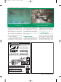
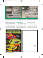
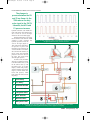
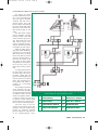
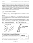
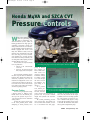
boyle-CVT.qxd
12/31/04
2:12 PM
Page 22
Honda M4VA and SZCA CVT
Pressure Controls
by Sean Boyle
W
hile some manufacturers are questioning their
faith in continuously variable transmissions (CVTs), others are
kicking production into high gear (or
something equivalent). Honda has
always been a leader in CVT technology and reliability, but the production of
Hondas equipped with CVTs is still
fairly low. Without a doubt, CVTs are
relatively rare transmissions. But with
fuel costs rising, the newer, fuel-efficient hybrids have recently become
more attractive to many consumers, and
one thing that makes hybrids practical
and fuel efficient is the CVT.
For now there are only two Honda
CVTs in production:
• M4VA in the 1996-to-2000
Civic HX
• SZCA in the 2001-to-current
HX, Insight, and Civic hybrids
The two models essentially operate
the same way, but there are differences
between them. Honda has refined the
electronics, hydraulics, and even the
mechanical configuration as the CVT
evolved from the M4VA to the SZCA.
Let’s look at how each of these Honda
CVTs achieves the pulley ratio changes
and sheave (pulley) pressure.
Pressure Testing
For the most part, pressure testing
a Honda vehicle is difficult. First,
Honda doesn’t use conventional pressure taps. The pressure tap is an 8 x
1.25 metric thread with an aluminum
sealing washer.
Second, they put the pressure taps
in the worst possible places. When
attempting to check pressures, have
22
Figure 1: While Honda provides pressure taps for nearly every circuit in the unit,
connecting your gauge to these taps often requires extensive plumbing.
plenty of fittings
and adapters on
hand to make life a
little easier. I’ve
resorted to making
homemade fittings
by drilling a small
1/8" hole through
the center of a bolt
and welding a 1/8"
pipe fitting to it
(figure 1).
On a positive
Figure 2: In failsafe, CVT pressures can exceed 500 PSI.
note, Honda proAlways use a pressure gauge with adequate range, or better
vides a pressure tap
yet, use a pressure transducer for hydraulic testing.
for most, if not all,
of the circuits in the transmission. So
Consider an electronic pressure transpressure tests can provide excellent
ducer, not only because of the ranges
insight into hydraulic and electronic
available, but for its recording capabilifailures.
ties. The pressure test shown is on a
Be careful performing pressure
CVT in failsafe mode (figure 2). Keep
tests on these units: The Honda CVT
in mind, the driven pulley pressure reachcan reach more than 500 PSI, so never
es 540 PSI. All this from a small, chainuse a conventional 300 PSI gauge.
driven, positive displacement pump.
GEARS January/February 2005
Life1-05.qxd
12/31/04
10:52 AM
Page 23
boyle-CVT.qxd
12/31/04
2:13 PM
Page 24
Honda M4VA and SZCA CVT Pressure Controls
Figure 3: Under normal operation, pressures are more
reasonable, although Honda doesn’t offer a complete set
of pressure specs.
If the CVT is operating correctly,
the normal pressure range isn’t that
alarming (figure 3). In neutral at 1700
RPM, you should expect 50 – 92 PSI at
the drive pulley, 92 – 140 PSI at the
driven pulley. In drive, you should have
228 – 267 at the forward clutch. The
lube circuit should produce 36 – 58 PSI
in neutral, at 3000 RPM.
The service manual doesn’t provide specifications for stall or moving
pressure ranges, but look for the start
Figure 4: The Honda CVT blends the pressures from
the PH/PL solenoid to adjust the width of the sheaves
(pulleys) and control drive ratio.
clutch, drive, and driven pulley pressures to increase with engine torque.
The relationship between drive and
driven pulley pressures will change as
you drive the vehicle. This changes the
effective ratio of the drive and driven
pulleys (figure 4).
Pressure Control
Honda relies on two pulse width
modulation (PWM) solenoids to control how much pressure each sheave
(pulley) receives. The design and
responsibility of each PWM solenoid is
different between the two generations
of transmissions (figures 5A and 5B).
Early CVT (M4VA)
A PH/PL solenoid controls overall
line pressure, which is also termed PH
(Pressure, High). The PH/PL solenoid
also controls PL (Pressure, Low),
which works with PH pressure to establish ratios and sheave pressure. Think
INTRODUCING
Platinum Torque is a new product
line developed by National
Drivetrain to usher in a higher
standard of quality parts and
rebuilt units at affordable prices.
Q UALITY REBUILT
Manual Transmissions & Transfer Cases
12
ED MILE SI
IT
L
M
ARRAN
RW
TY
VE
NTH UN
MO
LI
Member
Standard 12 Month Unlimited Mile Warranty.
Extended Warranties available
HUGE INVENTORY- VOLUME DISCOUNTS
Also: Complete Rebuild Kits with OE quality parts
Call and request a credit application today
TOLL FREE ORDER LINE
1-800-507-4327
You can order online and use our complete buyers guide at:
w w w. n a t i o n a l d r i v e t r a i n . c o m
24
Take Note:
We beat
anyone’s
published
price on
Ring and
Pinions
GEARS January/February 2005
boyle-CVT.qxd
12/31/04
2:13 PM
Page 25
Figures 5a and 5b: A look at the physical differences between the early (left) and late (right) CVT valve bodies.
of the PH/PL solenoid circuit as controlling the amount of pressure in the
CVT.
The Shift Control Solenoid is
responsible for distributing the PH and
PL pressure between the drive and driven pulleys. The shift control solenoid
acts on the shift control valve to deliver
a combination of PH and PL pressure to
a given pulley. The TCM then monitors
the speed ratio through one of its four
speed sensors and adjusts accordingly.
Think of the shift control solenoid as
controlling the pressure ratio between
the drive and driven pulleys.
Late CVT (SZCA)
The late model CVT valve body
looks similar to the earlier unit, but the
hydraulic functions have changed dramatically. A separate Drive Pressure
Control solenoid and Driven Pressure
Control solenoid replace the PH/PL
solenoid and the shift control solenoid
in the M4VA units, and satisfy all of the
pressure and ratio functions. Each solenoid will determine the amount of pressure for its respective pulley, in addition to influencing line pressure.
Here’s how it works:
Honda’s PWM solenoids mechanically assist the valves they control.
When energized, the solenoid pintle
extends, forcing the valve against
spring pressure. Take a look at the
1425 STAGECOACH RD
SHAKOPEE, MN 55379
VOICE 800-800-9274
FAX 952-445-0231
www.powerpusher.com
GEARS January/February 2005
25
boyle-CVT.qxd
12/31/04
2:13 PM
Page 26
Honda M4VA and SZCA CVT Pressure Controls
The changes in
pressure between the PH
and PL are linear: As the
TCM reduces the duty
cycle signal to the PH/PL
solenoids, both PH and
PL pressure increase.
hydraulic schematic: each PWM solenoid works along with regulated pressure to move its valve to the right,
which cuts off its own fluid supply.
When the PWM duty cycle is high,
the mechanical assist from the PWM
solenoid is high, requiring less
hydraulic pressure to move the
valve to the right (figure 6).
This creates lower solenoid signal pressure. If power were
interrupted at the solenoids, the
valves would have no mechanical assist from the solenoids, so
they’d require more hydraulic
pressure to move the valves to
the right. This would boost
solenoid signal pressure.
In earlier CVTs, the PH/PL
solenoid (6) regulated pressure
to the PH control valve (7) and
the PL control valve (5). The
PH control valve, as its name
implies, controls PH pressure,
which is basically line pressure
(figure 7). The PL control valve
lowers PH pressure, which
helps control the ratio between
the pulleys.
1
Driven Pulley
2
Drive Pulley
3
Shift Control Solenoid
4
Shift Control Valve
5
PL Regulator Valve
6
PH/PL Solenoid
7
PH Control Valve
8
PH Regulator Valve
Figure 6: The TCM controls the PH/PL solenoids with a variable duty cycled signal.
As signal on-time increases, pressure decreases.
Figure 7: On early Honda CVTs, the PH/PL solenoid (6) controls pressure for both pulleys; the shift control
solenoid (3) controls regulates how much pressure applies to each pulley.
26
GEARS January/February 2005
203PRE017 ALIEN 4C 12/16/04 2:48 PM Page 1
We have a
transmission solution
for any vehicle.
(Well, almost any)
As the’ technological leader,
Precision International s repair kits are truly state of the art.
Name any year, make or model. Give us any transmission problem.
Chances are we’ve got a solution. Not just any solution, but one that
will really work and keep on working – backed by solid engineering, the
latest specs and our reputation for giving you and your customers reliable
performance and the utmost peace of mind. When you
see the Precision International name on one of our
transmission repair kits, you can feel confident you’ve
got the very best. All are cross-checked against OEM
specs. All changes are noted and made. And we always use OE parts or
better. Spaceships? We haven’t helped repair one of those yet. But who
knows what tomorrow will bring!
CAUSE: The front pump seal may have been installed too
deeply into the converter housing. This can cause the seal
to block off half of the drain back hole in the pump, leading
to an increase in oil pressure behind the seal. Which, in turn,
can make the front seal pop out of the housing
or oil to blow past the seal between its lip
and converter hub.
SOLUTION: Precision International’s
redesigned Vamac® front pump seal
number 63704. It’s pre-notched and indexed
to avoid blocking the drain back hole. You can
order the seal, including complete installation
instructions, under the number Sub-K63704.
® Viton is a Registered Trademark of DuPont.
THE LATEST SOLUTION
FROM THE PROBLEM SOLVERS
RL4F02A/V – RE4F02A/V
PROBLEM: Before and/or after rebuilding a transmission, the vehicle
has repeated front seal leaks. The front seal may appear to have popped
out of the converter housing.
T H I S A D V E R T I S E M E N T P R E PA R E D B Y
Client: Precision International
LoBo & Petrocine
Job #: PRE-N-203
The Problem Solvers.
210 Knickerbocker Ave., Bohemia, NY 11716
(631) 567-2000 • Fax (631) 567-2640 • Toll Free: 800-872-6649
Florida Office:
455 Lakeview Drive, Coral Springs, FL 33071
(954) 509-9950 • Fax (954) 509-9945
E-mail: [email protected]
www.transmissionkits.com
Ad #: PRE-017
Ad Size: 8 125” x 10 875”
4/C
boyle-CVT.qxd
12/31/04
2:13 PM
Page 28
Honda M4VA and SZCA CVT Pressure Controls
The changes in pressure
between the PH and PL are linear: As the TCM reduces the
duty cycle signal to the PH/PL
solenoids, both PH and PL
pressure increase. The overall
pressure changes in the PH and
PL circuits, but the shift control
solenoid (3) still controls how
those pressures apply to each
pulley.
The shift control solenoid
receives modulator (solenoid)
pressure and alters it into shift
control solenoid signal pressure. This pressure acts on the
shift control solenoid valve,
which is responsible for delivering the PH and PL pressures
to the pulleys for ratio control.
When the PWM signal is
high, shift control solenoid signal pressure is low, moving the
shift control valve (4) toward
the left. This delivers more PH
pressure to the driven pulley (1)
and more PL pressure to the
drive pulley (2). This pressure
arrangement moves the pulleys
into a low ratio, such as you
might expect during acceleration.
As vehicle speed increases,
the shift control valve moves
toward the right. This reverses
the blend, sending more PH
pressure to the drive pulley, and
more PL pressure to the driven
pulley. This configuration creates a higher ratio, similar to
overdrive on a conventional
transmission.
The mechanical operations
of the late-model CVT solenoids are the same as the earlier
Figure 8: On later Honda CVTs, the drive and driven pulleys each have their own PH/PL
unit, but the hydraulic functions
solenoid, which also control overall line pressure.
are different. Look at the late
model CVT hydraulic schemat1
Driven Pulley
5
Driven Press Control
ic (figure 8): the drive (6) and driven
(5) pressure control solenoid signal
2
Drive Pulley
6
Drive Press Control
pressure affects drive and driven pressures as well as overall line pressure.
3
Driven Pulley Control
7
PH Control Valve
All of the valves in the CVT
except the reverse inhibit valve are bal4
Drive Pulley Control
8
PH Regulator Valve
ance-type valves, that regulate circuit
pressure by balancing hydraulic
pressure, spring force, and, in the case
of the solenoid-operated valves,
28
GEARS January/February 2005
borgWmorsetec.qxd
12/31/04
11:00 AM
Page 29
G O
S I G N I F I C A N T LY
B E YO N D
T H E C O M P E T I T I O N.
Go Beyond.
Borg Warner
makes OEM
Tradition
quality parts for
▼
over 80 transmissions
Engineering
world-wide, including
▼
FLEX-BAND ™,
Innovation
UNI-BAND ™ and
▼
MAJI-BAND ™
transmission bands,
Vision
friction plates and
▼
one-way clutches.
Leadership
▼
▼
Passion
▼
Performance
▼
Ambition
▼
Dedication
▼
S
ince 1928, the BorgWarner name has been synonymous with pioneering innovation in the
world-wide automotive industry. Our leadership in product development has resulted in an
impressive list of “firsts” – from the first mass produced automatic transmission to our recent
innovation of Torque on Demand (TOD) ™ systems for all-wheel drive. Today, BorgWarner
advances its long tradition of ambition and vision with new technology dedicated to high
energy applications and full systems product strategies for our OEM customers.
BorgWarner has available for your transmission shop virtually every automatic transmission
part we manufacture for the world’s leading vehicle makers. That’s more than 450 no-risk
OEM quality components for over eighty transmissions world-wide, including our new
line of high performance friction products for race-ready transmissions.
Go significantly beyond the competition. Make BorgWarner your one-stop source for automatic transmission parts that are competitively priced, readily available and guaranteed to fit
your rebuilds. Call your authorized distributor today and ask for the original parts from the
leader in automatic transmission technology…BorgWarner Inc.
Know How
The Borg Warner
Indianapolis 500 Trophy
is a registered trademark
of BorgWarner Inc.
BorgWarner Inc. Transmission Systems
1350 North Greenbriar Drive Unit B Addison, IL 60101 (630) 261-9980
www.bwauto.com
boyle-CVT.qxd
12/31/04
2:13 PM
Page 30
Honda M4VA and SZCA CVT Pressure Controls
Contamination is an
important issue with
CVT units: Whatever
you’re doing in a CVT,
keep it clean.
mechanical solenoid force. The late model CVTs have
greater control over how much pressure each pulley
receives, because they use separate solenoids and
hydraulic circuits for the drive and driven pulleys.
Both generations of CVT use low-resistance PWM
solenoids, measuring between 3.8 and 6.8 ohms. At room
temperature you should measure around 5 ohms. The
reverse inhibit solenoid is the only on/off solenoid in the
CVT, with between 11.7 and 21 ohms. The reverse inhibit solenoid works like other Honda on/off solenoids,
hydraulically trapping pressure when it’s de-energized.
Service Notes
You can reach all of the solenoids through the bottom
pan, but be careful with the electrical connectors: The
shift control solenoid and the start clutch solenoid use the
Figure 9: Be careful reconnecting the solenoids to the electrical
same connectors on early M4VA units. The drive pulley
harness; the connectors are identical, and can easily be crossed
pressure control solenoid and the start clutch solenoid
during reassembly.
have the same connector on SZCA units. These solenoid
connecters reach each other easily, and won’t look out of
place if you cross them (figure 9).
Contamination is an important issue with CVT units: Whatever
you’re doing in a CVT, keep it clean. Take a good look at the springs
that control the valve positions in the CVT: They’re very small and
have very little tension. It wouldn’t take much to hang a valve in this
valve body, so be careful and be extra clean when rebuilding these
units.
30
GEARS January/February 2005