1
®
5500A
Multi-Product Calibrator
Operator Manual
December 1994, Rev.11, 7/06
© 1994 - 2006 Fluke Corporation. All rights reserved. Printed in U.S.A.
All product names are trademarks of their respective companies.
LIMITED WARRANTY & LIMITATION OF LIABILITY
Each Fluke product is warranted to be free from defects in material and workmanship under
normal use and service. The warranty period is one year and begins on the date of shipment.
Parts, product repairs and services are warranted for 90 days. This warranty extends only to the
original buyer or end-user customer of a Fluke authorized reseller, and does not apply to fuses,
disposable batteries or to any product which, in Fluke's opinion, has been misused, altered,
neglected or damaged by accident or abnormal conditions of operation or handling. Fluke
warrants that software will operate substantially in accordance with its functional specifications
for 90 days and that it has been properly recorded on non-defective media. Fluke does not
warrant that software will be error free or operate without interruption.
Fluke authorized resellers shall extend this warranty on new and unused products to end-user
customers only but have no authority to extend a greater or different warranty on behalf of
Fluke. Warranty support is available if product is purchased through a Fluke authorized sales
outlet or Buyer has paid the applicable international price. Fluke reserves the right to invoice
Buyer for importation costs of repair/replacement parts when product purchased in one country
is submitted for repair in another country.
Fluke's warranty obligation is limited, at Fluke's option, to refund of the purchase price, free of
charge repair, or replacement of a defective product which is returned to a Fluke authorized
service center within the warranty period.
To obtain warranty service, contact your nearest Fluke authorized service center or send the
product, with a description of the difficulty, postage and insurance prepaid (FOB Destination), to
the nearest Fluke authorized service center. Fluke assumes no risk for damage in transit.
Following warranty repair, the product will be returned to Buyer, transportation prepaid (FOB
Destination). If Fluke determines that the failure was caused by misuse, alteration, accident or
abnormal condition of operation or handling, Fluke will provide an estimate of repair costs and
obtain authorization before commencing the work. Following repair, the product will be returned
to the Buyer transportation prepaid and the Buyer will be billed for the repair and return
transportation charges (FOB Shipping Point).
THIS WARRANTY IS BUYER'S SOLE AND EXCLUSIVE REMEDY AND IS IN LIEU OF ALL
OTHER WARRANTIES, EXPRESS OR IMPLIED, INCLUDING BUT NOT LIMITED TO ANY
IMPLIED WARRANTY OF MERCHANTABILITY OR FITNESS FOR A PARTICULAR
PURPOSE. FLUKE SHALL NOT BE LIABLE FOR ANY SPECIAL, INDIRECT, INCIDENTAL
OR CONSEQUENTIAL DAMAGES OR LOSSES, INCLUDING LOSS OF DATA, WHETHER
ARISING FROM BREACH OF WARRANTY OR BASED ON CONTRACT, TORT, RELIANCE
OR ANY OTHER THEORY.
Since some countries or states do not allow limitation of the term of an implied warranty, or
exclusion or limitation of incidental or consequential damages, the limitations and exclusions of
this warranty may not apply to every buyer. If any provision of this Warranty is held invalid or
unenforceable by a court of competent jurisdiction, such holding will not affect the validity or
enforceability of any other provision.
Fluke Corporation
P.O. Box 9090
Everett, WA 98206-9090
U.S.A.
5/94
Fluke Europe B.V.
P.O. Box 1186
5602 BD Eindhoven
The Netherlands
LIMITE DE GARANTIE ET LIMITE DE RESPONSABILITE
La société Fluke garantit l'absence de vices des matériaux et à la fabrication de ce produit dans
des conditions normales d'utilisation et d'entretien. La période de garantie est de un an et prend
effet à la date d'expédition. Les pièces, les réparations de produit et les services sont garantis
pour un période de 90 jours. Cette garantie ne s'applique qu'à l'acheteur d'origine ou à l'utilisateur
final s'il est client d'un distributeur agréé par Fluke, et ne s'applique pas aux fusibles, aux
batteries/piles interchangeables ni à aucun produit qui, de l'avis de Fluke, a été malmené, modifié,
négligé ou endommagé par accident ou soumis à des conditions anormales d'utilisation et de
manipulation. Fluke garantit que le logiciel fonctionnera en grande partie conformément à ses
spécifications fonctionnelles pour une période de 90 jours et qu'il a été correctement enregistré sur
des supports non défectueux. Fluke ne garantit pas que le logiciel ne contient pas d'erreurs ou
qu'il fonctionne sans interruption.
Les distributeurs agréés par Fluke appliqueront cette garantie à des produits vendus à leurs
clients neufs et qui n'ont pas servi mais ne sont pas autorisés à appliquer une garantie plus
étendue ou différente au nom de Fluke. Le support de garantie est offert si le produit a été acquis
par l'intermédiaire d'un point de vente agréé par Fluke ou bien si l'acheteur a payé le prix
international applicable. Fluke se réserve le droit de facturer à l'acheteur les frais d'importation des
pièces de réparation ou de remplacement si le produit acheté dans un pays a été expédié dans un
autre pays pour y être réparé.
L'obligation de garantie de Fluke est limitée, au choix de Fluke, au remboursement du prix d'achat,
ou à la réparation/remplacement gratuit d'un produit défectueux retourné dans le délai de garantie
à un centre de service agréé par Fluke.
Pour avoir recours au service de la garantie, mettez-vous en rapport avec le centre de service
Fluke le plus proche ou envoyez le produit, accompagné d'une description du problème, port et
assurance payés (franco lieu de destination), au centre de service agréé par Fluke le plus proche.
Fluke dégage toute responsabilité en cas de dégradations survenues au cours du transport. Après
la réparation sous garantie, le produit sera retourné à l'acheteur, frais de port payés d'avance
(franco lieu de destination). Si Fluke estime que le problème a été causé par un traitement abusif,
une modification, un accident ou des conditions de fonctionnement ou de manipulation anormales,
Fluke fournira un devis des frais de réparation et ne commencera la réparation qu'après en avoir
reçu l'autorisation. Après la réparation, le produit sera retourné à l'acheteur, frais de port payés
d'avance, et les frais de réparation et de transport lui seront facturés.
LA PRESENTE GARANTIE EST EXCLUSIVE ET TIENT LIEU DE TOUTES AUTRES
GARANTIES, EXPLICITES OU IMPLICITES, Y COMPRIS, MAIS NON EXCLUSIVEMENT,
TOUTE GARANTIE IMPLICITE QUANT A L'APTITUDE DU PRODUIT A ETRE COMMERCIALISE
OU A ETRE APPLIQUE A UNE FIN OU A UN USAGE DETERMINE. FLUKE NE POURRA ETRE
TENU RESPONSABLE D'AUCUN DOMMAGE PARTICULIER, INDIRECT, ACCIDENTEL OU
CONSECUTIF, NI D'AUCUNS DEGATS OU PERTES DE DONNEES, QUE CE SOIT A LA SUITE
D'UNE INFRACTION AUX OBLIGATIONS DE GARANTIE, SUR UNE BASE CONTRACTUELLE,
EXTRA- CONTRACTUELLE OU AUTRE.
Etant donné que certains pays ou états n'admettent pas les limitations d'une condition de garantie
implicite, ou l'exclusion ou la limitation de dégâts accidentels ou consécutifs, les limitations et les
exclusions de cette garantie pourraient ne pas s'appliquer à chaque acheteur. Si une disposition
quelconque de cette garantie est jugée non valide ou inapplicable par un tribunal compétent, une
telle décision n'affectera en rien la validité ou le caractère exécutoire de toute autre disposition.
Fluke Corporation
P.O. Box 9090
Everett, WA 98206-9090
USA
Fluke Europe B.V.
P.O. Box 1186
5602 B.D. Eindhoven
Pays-Bas
BEFRISTETE GARANTIEBESTIMMUNGEN & HAFTUNGSBESCHRÄNKUNG
Für jedes Produkt, das Fluke herstellt, leistet Fluke eine Garantie für einwandfreie Materialqualitßt und fehlerfreie
Ausführung unter normalen Betriebs- und Wartungsbedingungen. Der Garantiezeitraum gilt für ein Jahr und beginnt
mit dem Lieferdatum. Die Garantiebestimmungen für Ersatzteile, Instandsetzungs- und Wartungsarbeiten gelten für
einen Zeitraum von 90 Tagen. Diese Garantie wird ausschließlich dem Ersterwerber bzw. dem Endverbraucher, der
das betreffende Produkt von einer von Fluke autorisierten Weiterverkaufsstelle erworben hat, geleistet und erstreckt
sich nicht auf Sicherungen, Einwegbatterien oder irgendwelche andere Produkte, die nach dem Ermessen von
Fluke unsachgemäß verwendet, verändert, vernachlässigt, durch Unfälle beschädigt oder abnormalen
Betriebsbedingungen oder einer unsachgemäßen Handhabung ausgesetzt wurden. Fluke garantiert für einen
Zeitraum von 90 Tagen, daß die Software im wesentlichen in Übereinstimmung mit den einschlägigen
Funktionsbeschreibungen funktioniert und daß diese Software auf fehlerfreien Datenträgern gespeichert wurde.
Fluke übernimmt jedoch keine Garantie dafür, daß die Software fehlerfrei ist und störungsfrei arbeitet.
Von Fluke autorisierte Weiterverkaufsstellen werden diese Garantie ausschließlich für neue und nichtbenutzte, an
Endverbraucher verkaufte Produkte leisten, sind jedoch nicht dazu berechtigt, diese Garantie im Namen von Fluke
zu verlängern, auszudehnen oder in irgendeiner anderen Weise abzuändern. Der Erwerber hat das Recht aus der
Garantie abgeleitete Unterstützungsleistungen in Anspruch zu nehmen, wenn er das Produkt bei einer von Fluke
autorisierten Vertriebsstelle gekauft oder den jeweils geltenden internationalen Preis gezahlt hat. Fluke behält sich
das Recht vor, dem Erwerber Einfuhrgebühren für Ersatzteile in Rechnung zu stellen, wenn dieser das Produkt in
einem anderen Land zur Reparatur anbietet, als das Land, in dem er das Produkt ursprünglich erworben hat.
Flukes Garantieverpflichtung beschränkt sich darauf, daß Fluke nach eigenem Ermessen den Kaufpreis ersetzt oder
aber das defekte Produkt unentgeltlich repariert oder austauscht, wenn dieses Produkt innerhalb der Garantiefrist
einem von Fluke autorisierten Servicezentrum zur Reparatur übergeben wird.
Um die Garantieleistung in Anspruch zu nehmen, wenden Sie sich bitte an das nächstgelegene und von Fluke
autorisierte Servicezentrum oder senden Sie das Produkt mit einer Beschreibung des Problems und unter
Vorauszahlung von Fracht- und Versicherungskosten (FOB Bestimmungsort) an das nächstgelegene und von Fluke
autorisierte Servicezentrum. Fluke übernimmt keinerlei Haftung für eventuelle Transportschäden. Im Anschluß an
die Reparatur wird das Produkt unter Vorauszahlung von Frachtkosten (FOB Bestimmungsort) an den Erwerber
zurückgesandt. Wenn Fluke jedoch feststellt, daß der Defekt auf unsachgemäße Handhabung, Veränderungen am
Gerät, einen Unfall oder auf anormale Betriebsbedingungen oder unsachgemäße Handhabung zurückzuführen ist,
wird Fluke dem Erwerber einen Voranschlag der Reparaturkosten zukommen lassen und erst die Zustimmung des
Erwerbers einholen, bevor die Arbeiten in Angriff genommen werden. Nach der Reparatur wird das Produkt unter
Vorauszahlung der Frachtkosten an den Erwerber zurückgeschickt und werden dem Erwerber die Reparaturkosten
und die Versandkosten (FOB Versandort) in Rechnung gestellt.
DIE VORSTEHENDEN GARANTIEBESTIMMUNGEN SIND DAS EINZIGE UND ALLEINIGE RECHT AUF
SCHADENERSATZ DES ERWERBERS UND GELTEN AUSSCHLIESSLICH UND AN STELLE VON ALLEN
ANDEREN VERTRAGLICHEN ODER GESETZLICHEN GEWÄHRLEISTUNGSPFLICHTEN, EINSCHLIESSLICH JEDOCH NICHT DARAUF BESCHRÄNKT - DER GESETZLICHEN GEWÄHRLEISTUNG DER
MARKTFÄHIGKEIT, DER GEBRAUCHSEIGNUNG UND DER ZWECKDIENLICHKEIT FÜR EINEN BESTIMMTEN
EINSATZ. FLUKE ÜBERNIMMT KEINE HAFTUNG FÜR SPEZIELLE, UNMITTELBARE, MITTELBARE, BEGLEITODER FOLGESCHÄDEN ODER ABER VERLUSTE, EINSCHLIESSLICH DES VERLUSTS VON DATEN,
UNABHÄNGIG DAVON, OB SIE AUF VERLETZUNG DER GEWÄHRLEISTUNGSPFLICHT, RECHTMÄSSIGE,
UNRECHTMÄSSIGE ODER ANDERE HANDLUNGEN ZURÜCKZUFÜHREN SIND.
Angesichts der Tatsache, daß in einigen Ländern die Begrenzung einer gesetzlichen Gewährleistung sowie der
Ausschluß oder die Begrenzung von Begleit- oder Folgeschäden nicht zulässig ist, könnte es sein, daß die
obengenannten Einschränkungen und Ausschlüsse nicht für jeden Erwerber gelten. Sollte irgendeine Klausel dieser
Garantiebestimmungen von einem zuständigen Gericht für unwirksam oder nicht durchsetzbar befunden werden, so
bleiben die Wirksamkeit oder Erzwingbarkeit irgendeiner anderen Klausel dieser Garantiebestimmungen von einem
solchen Spruch unberührt.
Fluke Corporation
Postfach 9090
Everett, WA 98206-9090
USA
Fluke Europe B.V.
Postfach 1186
5602 B.D. Eindhoven
Niederlande
GARANTÍA LIMITADA Y LIMITACIÓN DE RESPONSABILIDAD
Se garantiza que cada uno de los productos de Fluke no tiene defectos de material y mano de
obra si es objeto de una utilización y un mantenimiento normales. El período de garantía es de
un año y comienza a partir de la fecha de envío. Las piezas, reparaciones y mantenimiento del
producto están garantizados durante 90 días. Esta garantía se concede exclusivamente al
comprador original o al cliente usuario final de un revendedor autorizado por Fluke, y no es de
aplicación a fusibles, baterías o pilas desechables o cualquier otro producto que, en opinión de
Fluke, haya sido objeto de una mala utilización, alteración, negligencia o daños por accidente o
manejo o manipulación anómalos. Fluke garantiza que el software operará sustancialmente de
acuerdo con sus especificaciones funcionales durante 90 días y que ha sido grabado
correctamente en medios no defectuosos. Fluke no garantiza que el software carezca de
errores ni opere sin interrupción.
Los revendedores autorizados por Fluke concederán esta garantía a productos nuevos y sin
utilizar suministrados a clientes usuarios finales exclusivamente, pero no tienen autoridad para
conceder una garantía diferente o mayor por cuenta de Fluke. Puede utilizar el servicio de
garantía si el producto ha si do comprado en una oficina de ventas Fluke autorizada o si el
Comprador ha pagado el importe de aplicación internacional. Fluke se reserva el derecho de
facturar al Comprador los costes de importación debidos a la reparación o sustitución de piezas
cuando el producto comprado en un país es enviado para su reparación a otro país.
La obligación de Fluke en concepto de garantía se limita, a criterio de Fluke, al reembolso del
importe de la compra, a la reparación gratis, o a la sustitución de un producto defectuoso que
sea devuelto a un centro de servicio Fluke autorizado dentro del período de garantía.
Para obtener servicio en garantía, póngase en contacto con el Servicio Oficial Fluke autorizado
más próximo o envíe el producto, con una descripción del problema surgido, a portes y seguros
pagados por anticipado (FOB en Destino), al Servicio Oficial Fluke autorizado más próximo.
Fluke no asume ningún riesgo por los daños en tránsito. Tras la reparación en concepto de
garantía, el producto será devuelto al Comprador, previo pago del transporte (FOB en Destino).
Si Fluke decide que la avería ha sido causada por una mala utilización, alteración, accidente o
manejo o manipulación anormales, Fluke hará una estimación de los costes de reparación y
solicitará autorización antes de comenzar el trabajo. Tras la reparación, el producto será
devuelto al Comprador, previo pago del transporte, y se facturarán al Comprador los gastos en
concepto de reparación y de transporte para su devolución (FOB en el Punto de envío).
ESTA GARANTÍA SE CONCEDE A TÍTULO ÚNICO Y EXCLUSIVO DEL COMPRADOR Y
SUSTITUYE A TODAS LAS DEMÁS GARANTÍAS, EXPRESAS O IMPLÍCITAS, INCLUYENDO,
PERO SIN LIMITARSE A, NINGUNA GARANTÍA IMPLÍCITA DE COMERCIABILIDAD O
IDONEIDAD PARA UN FIN O UN USO DETERMINADOS. FLUKE NO SE
RESPONSABILIZARÁ DE PÉRDIDAS O DAÑOS ESPECIALES, INDIRECTOS, IMPREVISTOS
O CONTINGENTES, INCLUIDA LA PÉRDIDA DE DATOS, YA SEAN PRODUCTO DE
VIOLACIÓN DE LA GARANTÍA O YA SEA EN RELACIÓN CON UN CONTRATO, POR
RESPONSABILIDAD CIVIL EXTRACONTRACTUAL, CONFIANZA O EN CUALQUIER OTRA
FORMA.
Dado que algunos países o estados no permiten la limitación del plazo de una garantía
implícita, ni la exclusión o limitación de daños imprevistos o contingentes, las limitaciones y
exclusiones de esta garantía pueden no ser de aplicación a todos los compradores. Si alguna
disposición de esta Garantía es considerada nula o no aplicable por un tribunal de justicia
competente, dicha consideración no afectará a la validez o aplicación de las demás
disposiciones.
Fluke Corporation
P.O. Box 9090
Everett, WA 98206-9090
ESTADOS UNIDOS
Fluke Europe B.V.
P.O. Box 1186
5602 B.D. Eindhoven
Holanda
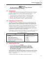
W CAUTION
This is an IEC safety Class 1 product. Before using, the ground wire in the
line cord or rear panel binding post must be connected to an earth ground
for safety.
Interference Information
This equipment generates and uses radio frequency energy and if not installed and used in
strict accordance with the manufacturer’s instructions, may cause interference to radio and
television reception. It has been type tested and found to comply with the limits for a Class B
computing device in accordance with the specifications of Part 15 of FCC Rules, which are
designed to provide reasonable protection against such interference in a residential installation.
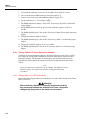
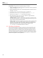
Operation is subject to the following two conditions:
•
This device may not cause harmful interference.
•
This device must accept any interference received, including interference that may cause
undesired operation.
There is no guarantee that interference will not occur in a particular installation. If this equipment
does cause interference to radio or television reception, which can be determined by turning the
equipment off and on, the user is encouraged to try to correct the interference by one of more of
the following measures:
•
Reorient the receiving antenna
•
Relocate the equipment with respect to the receiver
•
Move the equipment away from the receiver
•
Plug the equipment into a different outlet so that the computer and receiver are on different
branch circuits
If necessary, the user should consult the dealer or an experienced radio/television technician for
additional suggestions. The user may find the following booklet prepared by the Federal
Communications Commission helpful: How to Identify and Resolve Radio-TV Interference
Problems. This booklet is available from the U.S. Government Printing Office, Washington, D.C.
20402. Stock No. 004-000-00345-4.
Declaration of the Manufacturer or Importer
We hereby certify that the Fluke Model 5500A is in compliance with BMPT Vfg 243/1991 and is
RFI suppressed. The normal operation of some equipment (e.g. signal generators) may be
subject to specific restrictions. Please observe the notices in the users manual. The marketing
and sales of the equipment was reported to the Central Office for Telecommunication Permits
(BZT). The right to retest this equipment to verify compliance with the regulation was given to
the BZT.
Bescheinigung des Herstellers/Importeurs
Hiermit wird bescheinigt, daβ die Fluke Model 5500A in Übereinstimmung mit den
Bestimmungen der BMPT-AmtsblVfg 243/1991 funk-entstört sind. Der vorschriftsmäßige
Betrieb mancher Geräte (z.B. Meßsender) kann allerdings gewissen Einschränkungen
unterliegen. Beachten Sie deshalb die Hinweise in der Bedienungsanleitung. Dem Bundesamt
für Zulassungen in der Telecommunikation wurde das Inverkehrbringen dieses Gerätes
angezeigt und die Berechtigung zur Überprüfung der Serie auf Einhaltung der Bestimmungen
eingeräumt.
Fluke Corporation
SAFETY TERMS IN THIS MANUAL
This instrument has been designed and tested in accordance with IEC publication
1010-1 (1992-1), Safety Requirements for Electrical Measuring, Control and Laboratory
Equipment, and ANSI/ISA-582.01-1994, and CAN/CSA-C22.2 No. 1010.1-92. This User
Manual contains information, warning, and cautions that must be followed to ensure safe
operation and to maintain the instrument in a safe condition. Use of this equipment in a
manner not specified herein may impair the protection provided by the equipment.
This instrument is designed for IEC 1010-1 Installation Category II use. It is not designed
for connection to circuits rated over 4800 VA.
WARNING statements identify conditions or practices that could result in personal injury
or loss of life.
CAUTION statements identify conditions or practices that could result in damage to
equipment.
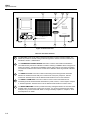
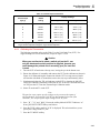
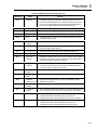
SYMBOLS MARKED ON EQUIPMENT
WARNING Risk of electric shock. Refer to the manual (see the Index for
references).
GROUND Ground terminal to chassis (earth).
Attention Refer to the manual (see the Index for references). This
symbol indicates that information about usage of a feature is contained in
the manual. This symbol appears on the rear panel ground post and by
the fuse compartment.
AC POWER SOURCE
The instrument is intended to operate from an ac power source that will not apply more
than 264V ac rms between the supply conductors or between either supply conductor
and ground. A protective ground connection by way of the grounding conductor in the
power cord is required for safe operation.
USE THE PROPER FUSE
To avoid fire hazard, for fuse replacement use only the specified unit: 110 or 120 V
operation, 2.5 ampere/250 volt time delay; 220 or 240 V operation, 1.25 ampere/250 volt
time delay.
GROUNDING THE INSTRUMENT
The instrument utilizes controlled overvoltage techniques that require the instrument to
be grounded whenever normal mode or common mode ac voltages or transient voltages
may occur. The enclosure must be grounded through the grounding conductor of the
power cord, or through the rear panel ground binding post.
USE THE PROPER POWER CORD
Use only the power cord and connector appropriate for the voltage and plug
configuration in your country.
Use only a power cord that is in good condition.
Refer power cord and connector changes to qualified service personnel.
DO NOT OPERATE IN EXPLOSIVE ATMOSPHERES
To avoid explosion, do not operate the instrument in an atmosphere of explosive gas.
DO NOT REMOVE COVER DURING OPERATION
To avoid personal injury or death, do not remove the instrument cover without first
removing the power source connected to the rear panel. Do not operate the instrument
without the cover properly installed. Normal calibration is accomplished with the cover
closed. Access procedures and the warnings for such procedures are contained both in
this manual and in the Service Manual. Service procedures are for qualified service
personnel only.
DO NOT ATTEMPT TO OPERATE IF PROTECTION MAY BE IMPAIRED
If the instrument appears damaged or operates abnormally, protection may be impaired.
Do not attempt to operate the instrument under these conditions. Refer all questions of
proper instrument operation to qualified service personnel.
Table of Contents
Chapter
1
Contents
Page
Introduction and Specifications......................................................... 1-1
1-1.
1-2.
1-3.
1-4.
1-5.
1-6.
1-7.
1-8.
1-9.
1-10.
1-11.
1-12.
1-13.
1-14.
1-15.
1-16.
1-17.
1-18.
1-19.
1-20.
1-21.
1-22.
1-23.
1-24.
1-25.
1-26.
1-27.
1-28.
Introduction...........................................................................................
How to Contact Fluke ...........................................................................
Operation Overview..............................................................................
Local Operation ................................................................................
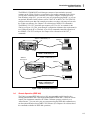
Remote Operation (RS-232).............................................................
Remote Operation (IEEE-488) .........................................................
Where To Go from Here .......................................................................
Instruction Manuals ..............................................................................
5500A Operator Manual...................................................................
5500A Operator Reference Guide ....................................................
5500A Remote Programming Reference Guide ...............................
5500A Service Manual .....................................................................
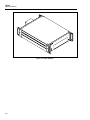
5725A Amplifier...................................................................................
Specifications........................................................................................
General Specifications ..........................................................................
DC Voltage Specifications ...............................................................
DC Current Specifications................................................................
Resistance Specifications .................................................................
AC Voltage (Sine Wave) Specifications ..........................................
AC Current (Sine Wave) Specifications...........................................
Capacitance Specifications ...............................................................
Temperature Calibration (Thermocouple) Specifications ................
Temperature Calibration (RTD) Specifications................................
DC Power Specification Summary...................................................
AC Power (45 Hz to 65 Hz) Specification Summary, PF=1 ............
Power and Dual Output Limit Specifications...................................
Phase Specifications .........................................................................
Calculating Power Uncertainty.........................................................
i
1-3
1-4
1-4
1-4
1-4
1-5
1-6
1-6
1-6
1-7
1-7
1-7
1-7
1-9
1-10
1-11
1-12
1-13
1-14
1-17
1-19
1-20
1-21
1-22
1-22
1-23
1-24
1-25
5500A
Operator Manual
1-29.
1-30.
1-31.
1-32.
1-33.
1-34.
1-35.
1-36.
1-37.
1-38.
1-39.
1-40.
1-41.
2
Introduction...........................................................................................
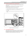
Unpacking and Inspection ....................................................................
Replacing The Fuse ..............................................................................
Selecting Line Voltage..........................................................................
Connecting To Line Power ...................................................................
Service Information ..............................................................................
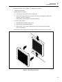
Placement and Rack Mounting .............................................................
Cooling Considerations.........................................................................
Connecting the 5725A Amplifier .........................................................
2-3
2-3
2-3
2-4
2-4
2-6
2-7
2-7
2-7
Features ............................................................................................... 3-1
3-1.
3-2.
3-3.
3-4.
4
1-26
1-26
1-26
1-27
1-28
1-29
1-29
1-29
1-29
1-30
1-31
1-31
1-31
Preparing for Operation ...................................................................... 2-1
2-1.
2-2.
2-3.
2-4.
2-5.
2-6.
2-7.
2-8.
2-9.
3
Additional Specifications......................................................................
Frequency Specifications..................................................................
Harmonics (2nd to 50th) Specifications..............................................
AC Voltage (Sine Wave) Extended Bandwidth Specifications........
AC Voltage (Non-Sine Wave) Specifications ..................................
AC Voltage, DC Offset Specifications.............................................
AC Voltage, Square Wave Characteristics.......................................
AC Voltage, Triangle Wave Characteristics (typical)......................
AC Current (Sine Wave) Extended Bandwidth Specifications ........
AC Current (Non-Sinewave) Specifications ....................................
AC Current (Non-Sinewave) Specifications (cont)..........................
AC Current, Square Wave Characteristics (typical).........................
AC Current, Triangle Wave Characteristics (typical) ......................
Introduction...........................................................................................
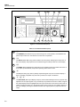
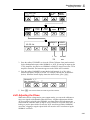
Front Panel Features .............................................................................
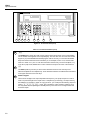
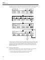
Rear Panel Features ..............................................................................
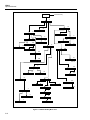
Softkey Menu Trees..............................................................................
3-3
3-3
3-3
3-3
Front Panel Operation......................................................................... 4-1
4-1.
4-2.
4-3.
4-4.
4-5.
4-6.
4-7.
4-8.
4-9.
4-10.
4-11.
4-12.
4-13.
4-14.
4-15.
4-16.
4-17.
Introduction...........................................................................................
Turning on the Calibrator .....................................................................
Warming up the Calibrator ...................................................................
Using the Softkeys ................................................................................
Using the Setup Menu...........................................................................
Using the Instrument Setup Menu ....................................................
Selecting an External Amplifier .......................................................
Utility Functions Menu ....................................................................
Using the Format EEPROM Menu ..............................................
Resetting the Calibrator ........................................................................
Zeroing the Calibrator...........................................................................
Using the Operate and Standby Modes.................................................
Connecting the Calibrator to a UUT.....................................................
Recommended Cable and Connector Types.....................................
When to Use EARTH.......................................................................
Four-Wire versus Two-Wire Connections .......................................
Cable Connection Instructions .........................................................
ii
4-3
4-3
4-4
4-4
4-4
4-5
4-5
4-6
4-6
4-7
4-7
4-8
4-9
4-9
4-10
4-10
4-11
4-18.
4-19.
4-20.
4-21.
4-22.
4-23.
4-24.
4-25.
4-26.
4-27.
4-28.
4-29.
4-30.
4-31.
4-32.
4-33.
4-34.
4-35.
4-36.
4-37.
4-38.
4-39.
4-40.
4-41.
4-42.
4-43.
4-44.
4-45.
4-46.
4-47.
4-48.
4-49.
4-50.
4-51.
4-52.
4-53.
4-54.
4-55.
4-56.
4-57.
4-58.
4-59.
4-60.
4-61.
4-62.
4-63.
4-64.
5
Rms Versus Peak-to-Peak Waveforms .................................................
Auto Range Versus Locked Range .......................................................
Setting the Output .................................................................................
Setting DC Voltage Output ..............................................................
Setting AC Voltage Output ..............................................................
Setting DC Current Output...............................................................
Setting AC Current Output...............................................................
Setting DC Power Output.................................................................
Setting AC Power Output.................................................................
Setting a Dual DC Voltage Output ...................................................
Setting a Dual AC Voltage Output ...................................................
Setting Resistance Output.................................................................
Setting Capacitance Output ..............................................................
Setting Temperature Simulation (Thermocouple) ............................
Setting Temperature Simulation (RTD) ...........................................
Measuring Thermocouple Temperatures..........................................
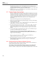
Waveform Types...................................................................................
Sinewave ..........................................................................................
Trianglewave ....................................................................................
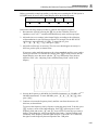
Squarewave ......................................................................................
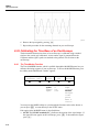
Truncated Sinewave .........................................................................
Setting Harmonics.................................................................................
Adjusting the Phase ..............................................................................
Entering a Phase Angle ....................................................................
Entering a Power Factor ...................................................................
Entering a DC Offset ............................................................................
Using the 5725A Amplifier ..................................................................
5725A Amplifier Output ..................................................................
Editing and Error Output Settings ........................................................
Editing the Output Setting ................................................................
Displaying the Output Error .............................................................
Using Multiply and Divide...............................................................
Setting Output Limits............................................................................
Setting Voltage and Current Limits..................................................
Sample Applications .............................................................................
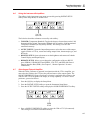
Calibrating an 80 Series Handheld Multimeter ................................
Cables ..........................................................................................
EARTH Connection .....................................................................
Testing the Meter .........................................................................
Calibrating the Meter ...................................................................
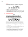
Testing a Model 41 Power Harmonics Analyzer..............................
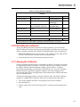
Testing Watts, VA, VAR Performance ........................................
Testing Harmonics Volts Performance ........................................
Testing Harmonics Amps Performance .......................................
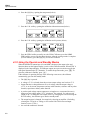
Calibrating a Fluke 51 Thermometer................................................
Testing the Thermometer .............................................................
Calibrating the Thermometer .......................................................
4-16
4-17
4-17
4-18
4-19
4-21
4-22
4-24
4-25
4-28
4-30
4-32
4-33
4-35
4-37
4-39
4-40
4-41
4-41
4-41
4-42
4-42
4-43
4-44
4-45
4-46
4-47
4-48
4-49
4-49
4-50
4-50
4-50
4-51
4-52
4-52
4-52
4-52
4-53
4-57
4-58
4-58
4-60
4-61
4-61
4-62
4-63
Remote Operation ............................................................................... 5-1
5-1.
Introduction........................................................................................... 5-4
iii
5500A
Operator Manual
5-2.
5-3.
5-4.
5-5.
5-6.
5-7.
5-8.
5-9.
5-10.
5-11.
5-12.
5-13.
5-14.
5-15.
5-16.
5-17.
5-18.
5-19.
5-20.
5-21.
5-22.
5-23.
5-24.
5-25.
5-26.
5-27.
5-28.
5-29.
5-30.
5-31.
5-32.
5-33.
5-34.
5-35.
5-36.
5-37.
5-38.
5-39.
5-40.
5-41.
5-42.
5-43.
5-44.
5-45.
5-46.
5-47.
5-48.
5-49.
5-50.
5-51.
5-52.
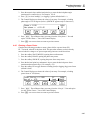
Setting up the IEEE-488 Port for Remote Control ...............................
IEEE-488 Port Setup Procedure .......................................................
Testing the IEEE-488 Port................................................................
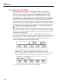
Setting up the RS-232 Host Port for Remote Control...........................
RS-232 Host Port Setup Procedure ..................................................
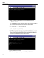
Testing the RS-232 Host Port...........................................................
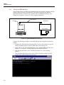
Testing RS-232 Host Port Operation using a Terminal ...............
Testing RS-232 Host Port Operation using Visual Basic ............
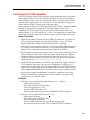
Setting up the RS-232 UUT Port for Remote Control..........................
RS-232 UUT Port Setup Procedure..................................................
Testing the RS-232 UUT Port via RS-232 Host Port.......................
Testing RS-232 UUT Port Operation via a Terminal ..................
Testing RS-232 UUT Port Operation using Visual Basic............
Testing the RS-232 UUT Port via IEEE-488 Port............................
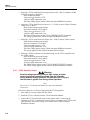
Changing between Remote and Local Operation .................................
Local State ........................................................................................
Local with Lockout State..................................................................
Remote State.....................................................................................
Remote with Lockout State ..............................................................
RS-232 Interface Overview ..................................................................
IEEE-488 Interface Overview...............................................................
Using Commands..................................................................................
Types of Commands.........................................................................
Device-Dependent Commands.....................................................
Common Commands....................................................................
Query Commands.........................................................................
Interface Messages (IEEE-488) ...................................................
Compound Commands.................................................................
Coupled Commands .....................................................................
Overlapped Commands ................................................................
Sequential Commands..................................................................
Commands that Require the Calibration Switch to be Enabled ...
Commands for RS-232 Only........................................................
Commands for IEEE-488 Only ....................................................
Command Syntax .............................................................................
Parameter Syntax Rules ...............................................................
Extra Space or Tab Characters .....................................................
Terminators ..................................................................................
Incoming Character Processing....................................................
Response Message Syntax ...........................................................
Checking 5500A Status ........................................................................
Serial Poll Status Byte (STB) ...........................................................
Service Request (SRQ) Line ........................................................
Service Request Enable Register (SRE).......................................
Programming the STB and SRE ..................................................
Event Status Register (ESR).............................................................
Event Status Enable (ESE) Register ............................................
Bit Assignments for the ESR and ESE.........................................
Programming the ESR and ESE...................................................
Instrument Status Register (ISR)......................................................
Instrument Status Change Registers.............................................
iv
5-4
5-7
5-8
5-10
5-10
5-12
5-12
5-14
5-15
5-15
5-17
5-17
5-18
5-19
5-21
5-21
5-21
5-21
5-21
5-22
5-23
5-25
5-25
5-25
5-26
5-26
5-26
5-28
5-28
5-29
5-29
5-29
5-29
5-30
5-31
5-31
5-32
5-33
5-33
5-34
5-35
5-35
5-37
5-37
5-38
5-38
5-38
5-38
5-39
5-40
5-40
5-53.
5-54.
5-55.
5-56.
5-57.
5-58.
5-59.
5-60.
5-61.
5-62.
5-63.
5-64.
5-65.
5-66.
6
5-40
5-40
5-42
5-42
5-43
5-43
5-43
5-44
5-45
5-45
5-45
5-46
5-46
5-47
Remote Commands............................................................................. 6-1
6-1.
6-2.
6-3.
7
Instrument Status Change Enable Registers.................................
Bit Assignments for the ISR, ISCR, and ISCE ............................
Programming the ISR, ISCR, and ISCE ......................................
Output Queue ...................................................................................
Error Queue ......................................................................................
Remote Program Examples...................................................................
Guidelines for Programming the Calibrator .....................................
Writing an SRQ and Error Handler ..................................................
Verifying a Meter on the IEEE-488 Bus ..........................................
Verifying a Meter on the RS-232 UUT Serial Port ..........................
Using *OPC?, *OPC, and *WAI .....................................................
Taking a Thermocouple Measurement .............................................
Using the RS-232 UUT Port to Control an instrument ....................
Input Buffer Operation .....................................................................
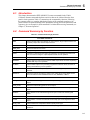
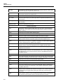
Introduction........................................................................................... 6-3
Command Summary by Function ......................................................... 6-3
Summary of Commands and Queries ................................................... 6-8
Maintenance......................................................................................... 7-1
7-1.
7-2.
7-3.
7-4.
7-5.
7-6.
7-7.
7-8.
7-9.
7-10.
7-11.
7-12.
7-13.
7-14.
7-15.
7-16.
7-17.
7-18.
7-19.
7-20.
7-21.
7-22.
7-23.
7-24.
7-25.
7-26.
7-27.
7-28.
7-29.
Introduction...........................................................................................
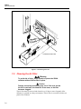
Replacing the Line Fuse .......................................................................
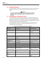
Cleaning the Air Filter ..........................................................................
General Cleaning ..................................................................................
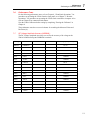
Performing a Calibration Check ...........................................................
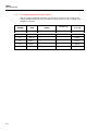
Performance Tests ............................................................................
DC Voltage Amplitude Accuracy (NORMAL) ...........................
DC Voltage Amplitude Accuracy (AUX) ....................................
DC Current Amplitude Accuracy.................................................
Resistance Accuracy ....................................................................
Resistance DC Offset Measurement.............................................
AC Voltage Amplitude Accuracy (NORMAL) ...........................
AC Voltage Amplitude Accuracy (AUX) ....................................
AC Current Amplitude Accuracy.................................................
Capacitance Accuracy ..................................................................
Thermocouple Measurement Accuracy .......................................
Thermocouple Sourcing Accuracy...............................................
Thermocouple Measuring Accuracy ............................................
DC Power Amplitude Accuracy (NORMAL)..............................
DC Power Amplitude Accuracy (AUX) ......................................
AC Power Amplitude Accuracy (High Voltage) .........................
AC Power Amplitude Accuracy (High Current)..........................
AC Power Amplitude Accuracy (High Power)............................
Phase and Frequency Accuracy ...................................................
AC Voltage Amplitude Accuracy, Squarewave (NORMAL)......
AC Voltage Amplitude Accuracy, Squarewave (AUX) ..............
AC Voltage Harmonic Amplitude Accuracy (NORMAL) ..........
AC Voltage Harmonic Amplitude Accuracy (AUX) ...................
DC Voltage Offset Accuracy .......................................................
v
7-3
7-3
7-4
7-6
7-6
7-7
7-7
7-8
7-9
7-10
7-11
7-12
7-13
7-14
7-16
7-17
7-17
7-17
7-18
7-18
7-19
7-19
7-20
7-21
7-22
7-23
7-24
7-25
7-25
5500A
Operator Manual
7-30.
7-31.
8
AC Voltage Accuracy with a DC Offset...................................... 7-26
Non-Operator Fuse Replacement.......................................................... 7-26
Oscilloscope Calibration Options...................................................... 8-1
5500A-SC600 Option ........................................................................... 8-3
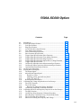
8-1.
8-2.
8-3.
8-4.
8-5.
8-6.
8-7.
8-8.
8-9.
8-10.
8-11.
8-12.
8-13.
8-14.
8-15.
8-16.
8-17.
8-18.
8-19.
8-20.
8-21.
8-22.
8-23.
8-24.
8-25.
8-26.
8-27.
8-28.
8-29.
8-30.
8-31.
8-32.
8-33.
8-34.
8-35.
8-36.
8-37.
8-38.
8-39.
8-40.
8-41.
8-42.
8-43.
8-44.
Introduction...........................................................................................
SC600 Option Specifications................................................................
Volt Specifications ...........................................................................
Edge Specifications ..........................................................................
Leveled Sine Wave Specifications ...................................................
Time Marker Specifications .............................................................
Wave Generator Specifications ........................................................
Pulse Generator Specifications.........................................................
Trigger Signal Specifications (Pulse Function)................................
Trigger Signal Specifications (Time Marker Function) ...................
Trigger Signal Specifications (Edge Function) ................................
Trigger Signal Specifications (Square Wave Voltage Function) .....
Trigger Signal Specifications ...........................................................
Oscilloscope Input Resistance Measurement Specifications............
Oscilloscope Input Capacitance Measurement Specifications .........
Overload Measurement Specifications .............................................
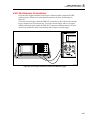
Oscilloscope Connections.....................................................................
Starting the SC600 Option....................................................................
The Output Signal ............................................................................
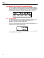
Adjusting the Output Signal .............................................................
Keying in a Value ........................................................................
Adjusting Values with the Rotary Knob ......................................
Using X and D ..................................................................
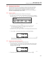
Resetting the SC600 Option .............................................................
Calibrating the Voltage Amplitude on an Oscilloscope........................
The VOLT Function .........................................................................
The V/DIV Menu .............................................................................
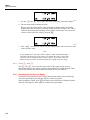
Shortcuts for Setting the Voltage Amplitude ...............................
Oscilloscope Amplitude Calibration Procedure ...............................
Calibrating the Pulse and Frequency Response on an Oscilloscope.....
The Edge Function ...........................................................................
Oscilloscope Pulse Response Calibration Procedure .......................
Pulse Response Calibration Using a Tunnel Diode Pulser...............
The Leveled Sine Wave Function ....................................................
Shortcuts for Setting the Frequency and Voltage.............................
The MORE OPTIONS Menu ...........................................................
Sweeping Through a Frequency Range............................................
Oscilloscope Frequency Response Calibration Procedure ...............
Calibrating the Time Base of an Oscilloscope......................................
The Time Marker Function ..............................................................
Time Base Marker Calibration Procedure for an Oscilloscope ........
Testing the Trigger................................................................................
Testing Video Triggers .........................................................................
Verifying Pulse Capture........................................................................
vi
8-5
8-5
8-6
8-7
8-8
8-9
8-9
8-10
8-11
8-11
8-11
8-11
8-11
8-12
8-12
8-12
8-13
8-13
8-14
8-14
8-14
8-15
8-15
8-15
8-16
8-16
8-17
8-17
8-18
8-19
8-19
8-20
8-21
8-21
8-22
8-23
8-24
8-24
8-26
8-26
8-27
8-28
8-30
8-31
8-45.
8-46.
8-47.
8-48.
8-49.
8-50.
8-51.
8-52.
8-53.
8-54.
8-55.
8-56.
8-57.
8-58.
8-59.
8-60.
8-61.
8-62.
8-63.
8-64.
8-65.
8-66.
8-67.
8-68.
8-69.
8-70.
8-71.
8-72.
8-73.
8-74.
8-75.
Measuring Input Resistance and Capacitance.......................................
Input Impedance Measurement ........................................................
Input Capacitance Measurement ......................................................
Testing Overload Protection .................................................................
Remote Commands and Queries...........................................................
General Commands ..........................................................................
Edge Function Commands ...............................................................
Marker Function Commands ............................................................
Video Function Commands ..............................................................
Overload Function Commands.........................................................
Impedance/Capacitance Function Commands..................................
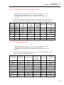
Verification Tables ...............................................................................
DC Voltage Verification...................................................................
AC Voltage Amplitude Verification.................................................
AC Voltage Frequency Verification.................................................
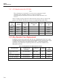
Wave Generator Amplitude Verification: 1 MΩ Output
Impedance.........................................................................................
Wave Generator Amplitude Verification: 50Ω Output Impedance..
Leveled Sinewave Verification: Amplitude .....................................
Leveled Sinewave Verification: Frequency .....................................
Leveled Sinewave Verification: Harmonics.....................................
Leveled Sinewave Verification: Flatness .........................................
Edge Verification: Amplitude ..........................................................
Edge Verification: Frequency...........................................................
Edge Verification: Duty Cycle .........................................................
Edge Verification: Rise Time ...........................................................
Tunnel Diode Pulser Verification.....................................................
Marker Generator Verification .........................................................
Pulse Generator Verification: Period................................................
Pulse Generator Verification: Pulse Width ......................................
Input Impedance Verification: Resistance........................................
Input Impedance Verification: Capacitance .....................................
8-32
8-32
8-33
8-33
8-34
8-35
8-38
8-38
8-38
8-39
8-40
8-41
8-41
8-42
8-42
8-43
8-44
8-45
8-45
8-46
8-47
8-53
8-53
8-53
8-54
8-54
8-55
8-55
8-55
8-56
8-56
5500A-SC300 Option ........................................................................... 8-57
8-76.
8-77.
8-78.
8-79.
8-80.
8-81.
8-82.
8-83.
8-84.
8-85.
8-86.
8-87.
8-88.
8-89.
8-90.
8-91.
Introduction...........................................................................................
Oscilloscope Calibration Option Specifications ...................................
Volt Function Specifications ............................................................
Edge Function Specifications ...........................................................
Leveled Sine Wave Function Specifications ....................................
Time Marker Function Specifications ..............................................
Wave Generator Specifications ........................................................
Trigger Signal Specifications for the Time Marker Function ..........
Trigger Signal Specifications for the Edge Function .......................
Oscilloscope Connections.....................................................................
Starting the Oscilloscope Calibration Option .......................................
The Output Signal ............................................................................
Adjusting the Output Signal .............................................................
Keying in a Value ........................................................................
Adjusting Values with the Rotary Knob ......................................
Using X and D ..................................................................
vii
8-59
8-60
8-60
8-61
8-62
8-63
8-63
8-64
8-64
8-65
8-66
8-66
8-67
8-67
8-67
8-68
5500A
Operator Manual
8-92.
8-93.
8-94.
8-95.
8-96.
8-97.
8-98.
8-99.
8-100.
8-101.
8-102.
8-103.
8-104.
8-105.
8-106.
8-107.
8-108.
8-109.
8-110.
8-111.
8-112.
8-113.
8-114.
8-115.
8-116.
8-117.
8-118.
8-119.
8-120.
8-121.
8-122.
9
Resetting the Oscilloscope Option ...................................................
Calibrating the Voltage Amplitude on an Oscilloscope........................
The Volt Function ............................................................................
The V/DIV Menu .............................................................................
Shortcuts for Setting the Voltage Amplitude ...............................
Amplitude Calibration Procedure for an Oscilloscope.....................
Calibrating the Pulse and Frequency Response on an Oscilloscope.....
The Edge Function ...........................................................................
Pulse Response Calibration Procedure for an Oscilloscope .............
The Leveled Sine Wave Function ....................................................
Shortcuts for Setting the Frequency and Voltage.............................
The MORE OPTIONS Menu ...........................................................
Sweeping through a Frequency Range .............................................
Frequency Response Calibration Procedure for an Oscilloscope.....
Calibrating the Time Base of an Oscilloscope......................................
The Time Marker Function ..............................................................
Time Base Marker Calibration Procedure for an Oscilloscope ........
Testing the Trigger................................................................................
Summary of Commands and Queries ...................................................
Verification Tables ...............................................................................
Voltage Function Verification: AC Voltage into a 1 MΩ Load.......
Voltage Function Verification: AC Voltage into a 50 Ω Load ........
Voltage Function Verification: DC Voltage into a 50 Ω Load ........
Voltage Function Verification: DC Voltage into a 1 MΩ Load.......
Edge Function Verification ..............................................................
Wave Generator Function Verification: 1 MΩ Load .......................
Wave Generator Function Verification: 50 Ω Load .........................
Leveled Sinewave Function Verification: Amplitude ......................
Leveled Sinewave Function Verification: Flatness ..........................
Leveled Sinewave Function Verification: Frequency ......................
Marker Generator Function Verification..........................................
8-68
8-69
8-69
8-70
8-70
8-71
8-72
8-72
8-73
8-74
8-74
8-75
8-77
8-78
8-80
8-80
8-81
8-82
8-83
8-86
8-86
8-87
8-88
8-89
8-90
8-90
8-91
8-91
8-92
8-95
8-96
Accessories ......................................................................................... 9-1
9-1.
9-2.
9-3.
9-4.
9-5.
9-6.
9-7.
Introduction...........................................................................................
Rack Mount Kit ....................................................................................
IEEE-488 Interface Cables ...................................................................
RS-232 Null-Modem Cables ................................................................
RS-232 Modem Cables.........................................................................
5500A/LEADS .....................................................................................
5725A Amplifier Accessory .................................................................
Index
viii
9-3
9-4
9-4
9-4
9-4
9-4
9-4
List of Tables
Table
2-1.
2-2.
3-1.
3-2.
3-3.
4-1.
4-2.
4-3.
4-4.
4-5.
4-6.
4-7.
5-2.
5-3.
5-4.
5-5.
5-6.
5-7.
5-8.
5-9.
5-10.
5-11.
6-1.
7-1.
7-2.
7-3.
9-1.
Page
Standard Equipment ...............................................................................................
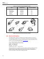
Line Power Cord Types Available from Fluke ......................................................
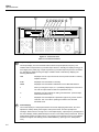
Front Panel Features...............................................................................................
Rear Panel Features................................................................................................
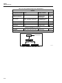
Factory Default Settings for the SETUP Menus ....................................................
Factory Defaults for SETUP ..................................................................................
UUT Connections...................................................................................................
Keys That Exit Error Mode....................................................................................
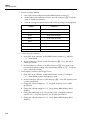
Watts Performance, Text Screen. ...........................................................................
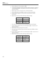
Harmonics Performance for Volts, Harmonics Screen ..........................................
Harmonics Performance for AMPS, Harmonics screen.........................................
Thermocouple Performance ...................................................................................
RS-232 Interface Wiring ........................................................................................
RS-232 Emulation of IEEE-488 Messages ............................................................
Interface Messages that the 5500A Accepts...........................................................
Interface Messages that the 5500A Sends..............................................................
Commands for RS-232 Only..................................................................................
Commands for IEEE-488 Only ..............................................................................
Units Accepted in Parameters and Used in Responses ..........................................
Terminator Characters............................................................................................
Response Data Types .............................................................................................
Status Register Summary .......................................................................................
Command Summary by Function ..........................................................................
Replacement Fuses.................................................................................................
Required Equipment for Checking Calibration......................................................
Non-Operator Fuse Replacement Locations ..........................................................
Options and Accessories ........................................................................................
ix
2-3
2-6
3-4
3-10
3-22
4-7
4-11
4-49
4-59
4-60
4-61
4-63
5-22
5-24
5-28
5-29
5-31
5-31
5-32
5-34
5-35
5-36
6-3
7-3
7-6
7-26
9-3
5500A
Operator Manual
x
List of Figures
Figure
1-1.
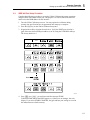
1-2.
1-3.
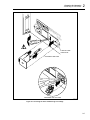
2-1.
2-2.
3-1.
3-2.
3-3.
3-4.
3-5.
3-6.
4-1.
4-2.
4-3.
4-4.
4-5.
4-6.
4-7.
4-9.
4-10.
4-11.
4-12.
4-13.
4-14.
4-15.
4-16.
4-17.
4-18.
4-19.
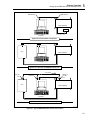
5-1.
5-2.
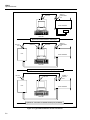
5-3.
5-4.
Page
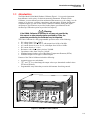
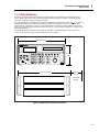
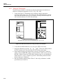
5500A Multi-Product Calibrator ............................................................................
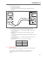
RS-232 Remote Connections .................................................................................
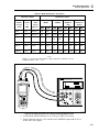
5725A Amplifier ....................................................................................................
Accessing the Fuse and Selecting Line Voltage ....................................................
Line Power Cord Types Available from Fluke ......................................................
Front Panel View....................................................................................................
Rear Panel View.....................................................................................................
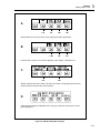
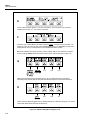
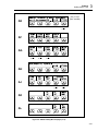
SETUP Softkey Menu Tree ...................................................................................
SETUP Softkey Menu Displays.............................................................................
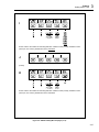
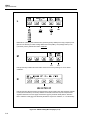
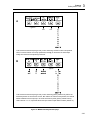
MEAS TC Softkey Menu Tree...............................................................................
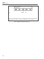
MEAS TC Softkey Menu Displays........................................................................
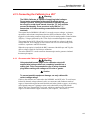
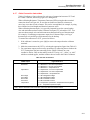
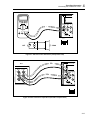
UUT Connection: Resistance (Four-Wire Compensation).....................................
UUT Connection: Resistance (Two-Wire Compensation).....................................
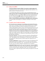
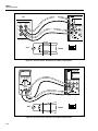
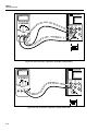
UUT Connection: Resistance (Compensation Off)................................................
UUT Connection: Capacitance (Four-Wire Compensation) ..................................
UUT Connection: Capacitance (Two-Wire Compensation) ..................................
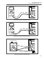
UUT Connection: Capacitance (Compensation Off) .............................................
UUT Connection: DC Voltage/AC Voltage...........................................................
UUT Connection: Temperature (RTD) ..................................................................
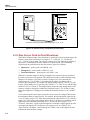
UUT Connection: Temperature (Thermocouple)...................................................
Sinewave ................................................................................................................
Trianglewave..........................................................................................................
Squarewave and Duty Cycle ..................................................................................
Truncated Sinewave ...............................................................................................
Cable Connections for Testing an 80 Series General Functions ............................
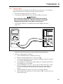
Cable Connections for Testing an 80 Series Current Function ..............................
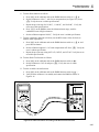
Cable Connections for Testing an 80 Series High Amps Function........................
Cable Connections for Testing a 40 Series Watts Function ...................................
Cable Connections for Testing a 50 Series Thermometer......................................
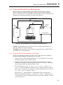
Typical IEEE-488 Remote Control Connections ...................................................
Typical RS-232 Remote Control Connections.......................................................
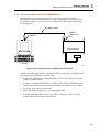
Typical IEEE-488 Port Connections ......................................................................
Typical PC COM Port Connections .......................................................................
xi
1-3
1-5
1-8
2-5
2-6
3-4
3-10
3-12
3-13
3-22
3-23
4-12
4-12
4-13
4-13
4-14
4-14
4-15
4-15
4-16
4-41
4-41
4-42
4-42
4-53
4-55
4-57
4-59
4-62
5-5
5-6
5-8
5-12
5500A
Operator Manual
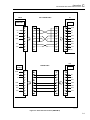
5-5.
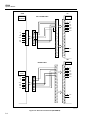
5-6.
5-7.
5-8.
5-9.
5-11.
7-1.
7-2.
Typical RS-232 UUT Port via RS-232 Host Port Connections .............................
Typical RS-232 UUT Port via IEEE-488 Port Connections ..................................
IEEE-488 Remote Message Coding.......................................................................
Status Register Overview .......................................................................................
Status Byte and SRE Bit Definitions......................................................................
Bit Assignments for the ISR, ISCEs and ISCRs ....................................................
Accessing the Fuse .................................................................................................
Accessing the Air Filter..........................................................................................
xii
5-17
5-19
5-25
5-37
5-38
5-42
7-4
7-5
Chapter 1
Introduction and Specifications
Contents
1-1.
1-2.
1-3.
1-4.
1-5.
1-6.
1-7.
1-8.
1-9.
1-10.
1-11.
1-12.
1-13.
1-14.
1-15.
1-16.
1-17.
1-18.
1-19.
1-20.
1-21.
1-22.
1-23.
1-24.
1-25.
1-26.
1-27.
1-28.
1-29.
1-30.
1-31.
1-32.
1-33.
1-34.
1-35.
Page
Introduction...........................................................................................
How to Contact Fluke ...........................................................................
Operation Overview..............................................................................
Local Operation ................................................................................
Remote Operation (RS-232).............................................................
Remote Operation (IEEE-488) .........................................................
Where To Go from Here .......................................................................
Instruction Manuals ..............................................................................
5500A Operator Manual...................................................................
5500A Operator Reference Guide ....................................................
5500A Remote Programming Reference Guide ...............................
5500A Service Manual .....................................................................
5725A Amplifier...................................................................................
Specifications........................................................................................
General Specifications ..........................................................................
DC Voltage Specifications ...............................................................
DC Current Specifications................................................................
Resistance Specifications .................................................................
AC Voltage (Sine Wave) Specifications ..........................................
AC Current (Sine Wave) Specifications...........................................
Capacitance Specifications ...............................................................
Temperature Calibration (Thermocouple) Specifications ................
Temperature Calibration (RTD) Specifications................................
DC Power Specification Summary...................................................
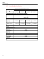
AC Power (45 Hz to 65 Hz) Specification Summary, PF=1 ............
Power and Dual Output Limit Specifications...................................
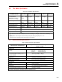
Phase Specifications .........................................................................
Calculating Power Uncertainty.........................................................
Additional Specifications......................................................................
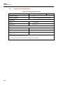
Frequency Specifications..................................................................
Harmonics (2nd to 50th) Specifications..............................................
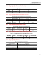
AC Voltage (Sine Wave) Extended Bandwidth Specifications........
AC Voltage (Non-Sine Wave) Specifications ..................................
AC Voltage, DC Offset Specifications.............................................
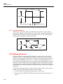
AC Voltage, Square Wave Characteristics.......................................
1-3
1-4
1-4
1-4
1-4
1-5
1-6
1-6
1-6
1-7
1-7
1-7
1-7
1-9
1-10
1-11
1-12
1-13
1-14
1-17
1-19
1-20
1-21
1-22
1-22
1-23
1-24
1-25
1-26
1-26
1-26
1-27
1-28
1-29
1-29
1-1
5500A
Operator Manual
1-36.
1-37.
1-38.
1-39.
1-40.
1-41.
1-2
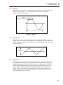
AC Voltage, Triangle Wave Characteristics (typical)......................
AC Current (Sine Wave) Extended Bandwidth Specifications ........
AC Current (Non-Sinewave) Specifications ....................................
AC Current (Non-Sinewave) Specifications (cont)..........................
AC Current, Square Wave Characteristics (typical).........................
AC Current, Triangle Wave Characteristics (typical) ......................
1-29
1-29
1-30
1-31
1-31
1-31
Introduction and Specifications
Introduction
1
1-1. Introduction
The Fluke Model 5500A Multi-Product Calibrator (Figure 1-1) is a precise instrument
that calibrates a wide variety of electrical measuring instruments. With the 5500A
Calibrator, you can calibrate precision multimeters that measure ac or dc voltage, ac or dc
current, ac or dc power, resistance, capacitance, and temperature. With the Oscilloscope
Calibration option, you can use the 5500A Calibrator to calibrate analog and digital
oscilloscopes. Specifications are provided in this chapter (specifications for the
Oscilloscope Calibration option are provided in Chapter 8).
XW Warning
If the 5500A Calibrator is operated in any way not specified by
this manual or other documentation provided by Fluke, the
protection provided by the Calibrator may be impaired.
The 5500A Calibrator is a fully programmable precision source of the following:
•
•
•
•
•
•
•
•
DC voltage from 0 V to +1020 V.
AC voltage from 1 mV to 1020 V, with output from 10 Hz to 500 kHz.
AC current from 0.01 µA to 11.0 A, with output from 10 Hz to 10 kHz.
DC current from 0 to +11.0 A.
Resistance values from a short circuit to 330 MΩ.
Capacitance values from 330 pF to 1100 µF.
Simulated output for three types of Resistance Temperature Detectors (RTDs).
Simulated output for nine types of thermocouples.
Features of the 5500A Calibrator include the following:
•
Automatic meter error calculation.
•
X and D keys that change the output value to pre-determined cardinal values
for various functions.
•
Programmable entry limits that prevent invalid amounts from being entered.
5500A CALIBRATOR
NORMAL
AUX
V, ,
RTD
A,
SCOPE
-SENSE,
AUX V
60V PK
MAX
STBY
OPR
EARTH
7
8
9
4
5
6
SCOPE
PREV
MENU
BOOST
HI
1000V
RMS
MAX
20V
RMS
MAX
TRIG
OUT
LO
1V PK
MAX
µ
m
n
k
dBm
sec
V
W
A
Hz
¡F
¡C
20V PK
MAX
1
2
3
0
•
20V PK
MAX
RESET
NEW
REF
CE
MEAS
TC
TRIG
OUT
MULT
DIV
EDIT
FIELD
p
M
F
TC
+/
SETUP
SHIFT
ENTER
x
÷
POWER
F1-01.eps
Figure 1-1. 5500A Multi-Product Calibrator
1-3
5500A
Operator Manual
•
Simultaneous output of voltage and current, up to 11 kW.
•
Simultaneous output of two voltages.
•
Extended bandwidth mode outputs multiple waveforms down to 0.01 Hz, and sine
waves to 2 MHz.
•
Variable phase signal output.
•
Standard IEEE-488 (GPIB) interface, complying with ANSI/IEEE Standards
488.1-1987 and 488.2-1987.
•
EIA Standard RS-232-C serial data interface for printing, displaying, or transferring
internally stored calibration constants, and for remote control of the 5500A.
•
Pass-through RS-232-C serial data interface for communicating with the Unit Under
Test (UUT).
•
Extensive automatic internal self testing and diagnostics of analog and digital
functions.
1-2. How to Contact Fluke
To contact Fluke, call one of the following telephone numbers:
USA: 1-888-99-FLUKE (1-888-993-5853)
Canada: 1-800-36-FLUKE (1-800-363-5853)
Europe: +31 402-675-200
Japan: +81-3-3434-0181
Singapore: +65-738-5655
Anywhere in the world: +1-425-446-5500
Or, visit Fluke's Web site at www.fluke.com.
To register your product, visit register.fluke.com.
1-3. Operation Overview
The 5500A Calibrator may be operated at the front panel in the local mode, or remotely
using RS-232 or IEEE-488 ports. For remote operations, several software options are
available to integrate 5500A operation into a wide variety of calibration requirements.
1-4
1-4.
Local Operation
Typical local operations include front panel connections to the Unit Under Test (UUT),
and then manual keystroke entries at the front panel to place the calibrator in the desired
output mode. The front panel layout facilitates hand movements from left to right, and
multiply and divide keys make it easy to step up or down at the press of a single key. You
can also review 5500A Calibrator specifications at the push of a button [available, July,
1995]. The backlit liquid crystal display is easy to read from many different viewing
angles and lighting conditions, and the large, easy-to-read keys are color-coded and
provide tactile feedback when they are pressed.
1-5.
Remote Operation (RS-232)
There are two rear-panel serial data RS-232 ports: SERIAL 1 FROM HOST, and
SERIAL 2 TO UUT (Figure 1-2). Each port is dedicated to serial data communications
for operating and controlling the 5500A during calibration procedures. For complete
information on remote operations, see Chapter 5.
Introduction and Specifications
Operation Overview
1
The SERIAL 1 FROM HOST serial data port connects a host terminal or personal
computer to the 5500A. You have several choices for sending commands to the 5500A:
you can enter commands from a terminal (for example, using the Terminal accessory
from Windows using a PC), you can write your own programs using BASIC, or you can
run optional Windows-based software such as 5500/CAL or MET/CAL. The 5500/CAL
software includes more than 200 example procedures covering a wide range of test tools
the 5500A can calibrate. (See Chapter 6 for a discussion of the RS-232 commands.)
The SERIAL 2 TO UUT serial data port connects a UUT to a PC or terminal via the
5500A (see Figure 1-2). This “pass-through” configuration eliminates the requirement for
two COM ports at the PC or Terminal. A set of four commands control the operation of
the SERIAL 2 TO UUT serial port. See Chapter 6 for a discussion of the UUT_*
commands.
SERIAL 1 FROM HOST port
COM port
PC or Terminal
5500A
RS-232 Remote Operation using the
SERIAL 1 FROM HOST port
SERIAL 1 FROM HOST port
SERIAL 2
TO UUT port
COM port
PC or Terminal
5500A
RS-232 Remote Operation using the
SERIAL 1 FROM HOST and
SERIAL 2 TO UUT ports
Unit Under Test
F1-02.eps
Figure 1-2. RS-232 Remote Connections
1-6.
Remote Operation (IEEE-488)
The 5500A rear panel IEEE-488 port is a fully programmable parallel interface bus
meeting standard IEEE-488.1 and supplemental standard IEEE-488.2. Under the remote
control of an instrument controller, the 5500A Calibrator operates exclusively as a
“talker/listener.” You can write your own programs using the IEEE-488 command set or
run the optional Windows-based MET/CAL software. (See Chapter 6 for a discussion of
the commands available for IEEE-488 operation.)
1-5
5500A
Operator Manual
1-7. Where To Go from Here
To locate specific information concerning the installation and operation of the 5500A
calibrator, refer to the following list:
•
Unpacking and setup: Chapter 2, “Preparing for Operation”
•
Installation and rack mounting: Chapter 2, “Preparing for Operation,” and the rack
mount kit instruction sheet
•
AC line power and interface cabling: Chapter 2, “Preparing for Operation”
•
Controls, indicators, and displays: Chapter 3, “Features”
•
Front panel operation: Chapter 4, “Front Panel Operation”
•
Cabling to a UUT (Unit Under Test): Chapter 4, “Front Panel Operation”
•
Using the auxiliary amplifier: Chapter 4, “Front Panel Operation”
•
Remote operation (IEEE-488 or serial): Chapter 5, “Remote Operation”
•
Calibrating an Oscilloscope: Chapter 8, “Oscilloscope Calibration Option”
•
Accessories to the 5500A Calibrator: Chapter 9, “Accessories”
•
Instrument specifications: Chapter 1, “Introduction and Specifications”
1-8. Instruction Manuals
The 5500A Manual Set provides complete information for opearators and service or
maintenance technicians. The set includes:
•
5500A Getting Started Manual (PN 945159)
•
5500A Operator Reference Guide (PN 945097)
•
5500A Remote Programming Reference Guide (PN 105783)
•
5500A Operator Manual (Provided on CD-ROM or printed copy available for
purchase (PN 1628802) through the Fluke Service Department.)
•
5500A Service Manual (PN 105798)
The two reference guides and the Getting Started manual are shipped with the unit. Order
additional copies of the manuals or reference guides separately using the part number
provided. For ordering instructions, refer to the Fluke Catalog, or ask a Fluke sales
representative (see “Service Information” in Chapter 2). The Operator and Service
Manuals are both provided on the CD-ROM.
1-9.
1-6
5500A Operator Manual
This 5500A Operator Manual provides complete information for installing the 5500A
Calibrator and operating it from the front panel keys and in remote configurations. This
manual also provides a glossary of calibration, specifications, and error code information.
The Operator Manual includes the following topics:
•
Installation
•
Operating controls and features, including front panel operation
•
Remote operation (IEEE-488 bus or serial port remote control)
•
Serial port operation (printing, displaying, or transferring data, and setting up for
serial port remote control)
Introduction and Specifications
5725A Amplifier
•
Operator maintenance, including verification procedures and calibration approach for
the 5500A
•
Oscilloscope Calibration Option
1
• Accessories
1-10. 5500A Operator Reference Guide
The 5500A Operator Reference Guide contains a summary of operating instructions, and
a front panel and rear panel feature reference.
1-11. 5500A Remote Programming Reference Guide
The 5500A Remote Programming Reference Guide contains a summary of remote
commands and reference information useful in determining system status using the status
byte and related registers.
1-12. 5500A Service Manual
The 5500A Service Manual can be ordered through your local Fluke Sales or Service
representative (see “Service Information” in Chapter 2). The 5500A Service Manual
includes: theory of operation, performance testing, maintenance, calibration,
troubleshooting, parts lists, and schematic diagrams.
1-13. 5725A Amplifier
The Fluke 5725A Amplifier (Figure 1-3) is an external unit operating under 5500A
control to extend the Volts x Hertz and voltage compliance of the calibrator. The
amplifier adds the following capabilities with no compromise in accuracy:
Frequency Increase to 100 kHz at 750 V, 30 kHz at 1020 V.
AC Voltage Load limit extended to 70 mA for frequencies above 5 kHz, and to 50 mA
for frequencies less than 5 kHz. Capacitive drive increases to 1020 pF, subject to the
maximum output current, for volts ac.
AC Current 11 A load limit extended to 10 kHz, with a 3-volt drive compliance.
A separate set of binding posts on the front panel of the 5725A supplies extended
capability. Since most meters have a separate input terminal for the high current ranges,
this eliminates the need to change cables during a procedure.
1-7
5500A
Operator Manual
F1-03.eps
Figure 1-3. 5725A Amplifier
1-8
Introduction and Specifications
Specifications
1
1-14. Specifications
The following paragraphs detail specifications for the 5500A Calibrator. The specifications are valid after allowing a
warm-up period of 30 minutes, or twice the time the 5500A has been turned off. For example, if the 5500A has been
turned off for 5 minutes, the warm-up period is 10 minutes.
All specifications apply for the temperature and time period indicated. For temperatures outside of tcal + 5 °C (tcal is the
ambient temperature when the 5500A was calibrated), the temperature coefficient is less than 0.1 times the 90-day
specifications per °C (limited to 0 °C to 50 °C). These specifications also assume the 5500A Calibrator is zeroed every
seven days or when the ambient temperature changes more than 5 °C. (See “Zeroing the Calibrator” in Chapter 4 of the
5500A Operator Manual.)
Also see additional specifications later in this chapter for information on extended specifications for ac voltage and
current. The dimensional outline for the 5500A Calibrator is shown in Figure A.
43.2 cm (17 in)
5500A CALIBRATOR
NORMAL
SCOPE
AUX
V, ,
RTD
A,
-SENSE,
AUX V
200V PK
MAX
STBY
OPR
EARTH
SCOPE
17.8 cm
(7 in)
PREV
MENU
BOOST
HI
1000V
RMS
MAX
20V
RMS
MAX
TRIG
OUT
LO
7
8
9
4
5
6
1
2
3
+/
0
µ
dBm
m
n
W
k
sec
V
Hz
¡F
A
NEW
REF
CE
F
MEAS
TC
TRIG
OUT
MULT
DIV
p
M
TC
20V PK
MAX
SHIFT
RESET
¡C
1V PK
MAX
20V PK
MAX
SETUP
ENTER
x
EDIT
FIELD
POWER
I
O
47.0 cm (18.5 in)
6.4 cm
(2.5 in)
For Cable
Access
om002f.ewps
Figure A. 5500A Calibrator Dimensional Outline
1-9
5500A
Operator Manual
1-15. General Specifications
Warmup Time
Settling Time
Standard Interfaces
Temperature Performance
Twice the time since last warmed up, to a maximum of 30 minutes.
Less than 5 seconds for all functions and ranges except as noted.
IEEE-488 (GPIB), RS-232, 5725ª Amplifier
Temperature Coefficient
Temperature Coefficient for temperatures outside tcal +5 °C is 0.1X/ °C of the
90-day specification (or 1-year, as applicable) per °C.
Relative Humidity
[1]
Altitude
Safety
Analog Low Isolation
EMC
Line Power
Power Consumption
Dimensions
Weight (without options)
Absolute Uncertainty Definition
Specification Confidence
Interval
[1]
1-10
• Operating: 0 °C to 50 °C
• Calibration (tcal): 15 °C to 35 °C
• Storage: -20 °C to 70 °C
• Operating: <80 % to 30 °C, <70 % to 40 °C, <40 % to 50 °C
• Storage: <95 %, non-condensing
• Operating: 3,050 m (10,000 ft) maximum
• Non-operating: 12,200 m (40,000 ft) maximum
Complies with IEC 1010-1 (1992-1); ANSI/ISA-S82.01-1994;
CAN/CSA-C22.2 No. 1010.1-92
20 V
Designed to comply with FCC Rules Part 15; VFG 243/1991. If used in areas with
Electromagnetic fields of 1 to 3 V/m, resistance outputs have a floor adder of
0.508 Ω. Performance not specified above 3 V/m. This instrument may be
susceptible to electro-static discharge (ESD) from direct contact to the binding posts.
Good static aware practices should be followed when handling this and other pieces
of electronic equipment.
• Line Voltage (selectable): 100 V, 120 V, 220 V, 240 V
• Line Frequency: 47 Hz to 63 Hz
• Line Voltage Variation: ±10 % about line voltage setting
5500A Calibrator, 300 VA; 5725A Amplifier, 750 VA
5500A Calibrator:
• Height: 17.8 cm (7 in), standard rack increment, plus 1.5 cm (0.6 in) for feet on
bottom of unit
• Width, 43.2 cm (17 in), standard rack width
• Depth: 47.3 cm (18.6 in) overall
5725A Amplifier:
• Height, 13.3 cm (5.25 in), standard rack increment, plus 1.5 cm (0.6 in) for feet on
bottom of unit
• Width, 43.2 cm (17 in), standard rack width
• Depth, 63.0 cm (24.8 in) overall.
5500A Calibrator, 22 kg (49 lb); 5725A Amplifier 32 kg (70 lb)
The 5500A specifications include stability, temperature coefficient, linearity, line and
load regulation, and the traceability of the external standards used for calibration.
You do not need to add anything to determine the total specification of the 5500A for
the temperature range indicated.
99 %
After long periods of storage at high humidity, a drying out period (with the power on) of at least one week may be required.
Introduction and Specifications
General Specifications
1
1-16. DC Voltage Specifications
Range
Absolute Uncertainty, tcal ± 5 °C
± (% of output + µV)
90 days
Stability
24 hours, ± 1 °C
± (ppm output + µV)
1 year
Resolution
µV
Maximum
[1]
Burden
0 to 329.9999 mV
0.005
3
0.006
3
5+1
0.1
50 Ω
0 to 3.299999 V
0.004
5
0.005
5
4+3
1
10 mA
0 to 32.99999 V
0.004
50
0.005
50
4 + 30
10
10 mA
30 to 329.9999 V
0.0045
500
0.0055
500
4.5 + 300
100
5 mA
100 to 1020.000 V
0.0045
1500
0.0055
1500
4.5 + 900
1000
5 mA
Auxiliary Output (dual output mode only)
[2]
0 to 329.999 mV
0.03
350
0.04
350
30 + 100
1
5 mA
0.33 to 3.3 V
0.03
350
0.04
350
30 + 100
10
5 mA
[1]
Remote sensing is not provided. Output resistance is < 5 mΩ for outputs ≥ 0.33 V. The AUX output has an output resistance
of < 1 Ω.
[2]
Two channels of dc voltage output are provided.
Noise
Range
Bandwidth 0.1 to 10 Hz p-p
± (ppm output + µV)
Bandwidth 10 to 10 kHz rms
0 to 329.9999 mV
1 µV
4 µV
0 to 3.299999 V
10 µV
50 µV
600 µV
0 to 32.99999 V
100 µV
30 to 329.9999 V
10 ppm + 1 mV
20 mV
100 to 1020.000 V
10 ppm + 5 mV
20 mV
Auxiliary Output (dual output mode only)
[1]
0 to 329.999 mV
5 µV
20 µV
0.33 to 3.3 V
20 µV
200 µV
[1]
Two channels of dc voltage output are provided.
1-11
5500A
Operator Manual
1-17. DC Current Specifications
Absolute Uncertainty,
tcal ± 5 °C
± (% of output + µA)
Range
90 days
Resolution
Compliance
Voltage
Maximum
Inductive
Load
1 µH
1 year
0 to 3.29999 mA
0.010
0.05
0.013
0.05
0.01 µA
4.5 V
0 to 32.9999 mA
0.008
0.25
0.01
0.25
0.1 µA
4.5 V
0 to 329.999 mA
0.008
3.3
0.01
3.3
1 µA
4.5 to 3.0 V
[1]
200 µH
0 to 2.19999 A
0.023
44
0.03
44
10 µA
4.5 to 3.4 V
[2]
200 µH
0 to 11 A
0.038
330
0.06
330
100 µA
4.3 to 2.5 V
[3]
200 µH
200 µH
5725A Amplifier
0 to 11 A
0.03
330
0.04
330
100
4V
[1]
The actual voltage compliance (Vc) is a function of current output (Io), and is given by the formula:
Vc = -5.05*Io+4.67. The highest compliance voltage is limited to 4.5 V.
[2]
The actual voltage compliance (Vc) is a function of current output (Io), and is given by the formula:
Vc = -0.588*Io+4.69. The highest compliance voltage is limited to 4.5 V.
[3]
The actual voltage compliance (Vc) is a function of current output (Io), and is given by the formula:
Vc = -0.204*Io+4.75. The highest compliance voltage is limited to 4.3 V.
Noise
Bandwidth
0.1 to 10 Hz
p-p
Bandwidth
10 to 10 kHz
rms
0 to 3.29999 mA
20 nA
200 nA
0 to 32.9999 mA
200 nA
2.0 µA
0 to 329.999 mA
2000 nA
20 µA
0 to 2.19999 A
20 µA
1 mA
0 to 11 A
200 µA
Ranges
10 mA
5725A Amplifier
0 to 11 A
1-12
± 25 ppm of output + 200 nA
2 mA
400 µH
Introduction and Specifications
General Specifications
1
1-18. Resistance Specifications
Range
Absolute Uncertainty, tcal ± 5 °C
[2]
± (% of output + Ω)
[1]
90 days
0 to 10.99 Ω
0.009
Resolution
Ω
1 year
Allowable
[4]
Current
0.008
[3]
0.012
0.008
[3]
0.001
1 to 125 mA
0.012
0.015
[3]
0.001
1 to 125 mA
0.009
0.015
[3]
0.001
1 to 70 mA
[3]
11 to 32.999 Ω
0.009
0.015
[3]
33 to 109.999 Ω
0.007
0.015
[3]
[3]
110 to 329.999 Ω
0.007
0.015
0.009
0.015
0.001
1 to 40 mA
330 Ω to 1.09999 kΩ
0.007
0.06
0.009
0.06
0.01
250 µA to 18 mA
1.1 to 3.29999 kΩ
0.007
0.06
0.009
0.06
0.01
250 µA to 5 mA
3.3 to 10.9999 kΩ
0.007
0.6
0.009
0.6
0.1
25 µA to 1.8 mA
11 to 32.9999 kΩ
0.007
0.6
0.009
0.6
0.1
25 µA to 0.5 mA
33 to 109.999 kΩ
0.008
6
0.011
6
1
2.5 µA to 0.18 mA
110 to 329.999 kΩ
0.009
6
0.012
6
1
2.5 µA to 0.05 mA
330 kΩ to 1.09999 MΩ
0.011
55
0.015
55
10
250 nA to 0.018 mA
1.1 to 3.29999 MΩ
0.011
55
0.015
55
10
250 nA to 5 µA
3.3 to 10.9999 MΩ
0.045
550
0.06
550
100
25 nA to 1.8 µA
11 to 32.9999 MΩ
0.075
550
0.1
550
100
25 nA to 0.5 µA
33 to 109.999 MΩ
0.4
5500
0.5
5500
1000
2.5 nA to 0.18 µA
110 to 330 MΩ
0.4
16500
0.5
16500
1000
2.5 nA to 0.06 µA
[1]
Continuously variable from 0 to 330 MΩ.
[2]
Applies for COMP OFF (to the 5500A Calibrator front panel NORMAL terminals) and 2-wire and 4-wire compensation.
[3]
The floor adder is improved to 0.006 Ω (0 to 10.99 Ω range) and 0.010 Ω (11 to 329.999 Ω) if the 5500A Calibrator is zeroed
(ohms zero or instrument zero) within 8 hours and temperature is ±1 °C of zeroing ambient temperature.
[4]
Do not exceed the largest current for each range. For currents lower than shown, the floor adder
increases by
Floor(new) = Floor(old) x Imin/Iactual. For example, a 100 µA stimulus measuring 100 Ω has a floor uncertainty of 0.01 Ω x 1
mA/100 µA = 0.1 Ω.
Range
Maximum Voltage
[1]
Maximum Lead Resistance
0 to 10.99 Ω
1.37 V
<3.2 Ω
11 to 32.999 Ω
4.12 V
<3.2 Ω
33 to 109.999 Ω
7.7 V
<3.2 Ω
110 to 329.999 Ω
13.2 V
<3.2 Ω
330 Ω to 1.09999 kΩ
19.8 V
<6 Ω
1.1 to 3.29999 kΩ
16.5 V
<6 Ω
3.3 to 10.9999 kΩ
19.8 V
<6 Ω
11 to 32.9999 kΩ
16.5 V
<6 Ω
33 to 109.999 kΩ
19.8 V
<6 Ω
110 to 329.999 kΩ
16.5 V
330 kΩ to 1.09999 MΩ
19.8 V
1.1 to 3.29999 MΩ
16.5 V
3.3 to 10.9999 MΩ
19.8 V
11 to 32.9999 MΩ
16.5 V
33 to 109.999 MΩ
19.8 V
110 to 330 MΩ
19.8 V
[2]
(n/a 110 kΩ and above)
[1]
This is for the largest resistance for each range. The maximum voltage for other values is Imax (highest value of Allowable Current
above) multiplied by Rout.
[2]
Maximum lead resistance for no additional error in 2-wire COMP.
1-13
5500A
Operator Manual
1-19. AC Voltage (Sine Wave) Specifications
Range
Frequency
Absolute Uncertainty, tcal ± 5 °C
± (% of output + µV)
90 days
1.0 to 32.999 mV
33 to 329.999 mV
0.33 to 3.29999 V
3.3 to 32.9999 V
33 to 329.999 V
330 to 1020 V
1-14
Resolution
Max
[1]
Burden
1 µV
50 Ω
1 µV
50 Ω
10 µV
10 mA
100 µV
10 mA
1 mV
5 mA, except
20 mA for
45 to 65 Hz
10 mV
2 mA, except
6 mA for
45 to 65 Hz
1 year
10 to 45 Hz
0.26
20
0.35
20
45 Hz to 10 kHz
0.11
20
0.15
20
10 to 20 kHz
0.15
20
0.2
20
20 to 50 kHz
0.19
20
0.25
20
50 to 100 kHz
0.26
33
0.35
33
100 to 500 kHz
0.75
60
1
60
10 to 45 Hz
0.19
50
0.25
50
45 Hz to 10 kHz
0.04
20
0.05
20
10 to 20 kHz
0.08
20
0.1
20
20 to 50 kHz
0.12
40
0.16
40
50 to 100 kHz
0.17
170
0.24
170
100 to 500 kHz
0.53
330
0.7
330
10 to 45 Hz
0.11
250
0.15
250
45 Hz to 10 kHz
0.02
60
0.03
60
10 to 20 kHz
0.06
60
0.08
60
20 to 50 kHz
0.10
300
0.14
300
50 to 100 kHz
0.17
1700
0.24
1700
100 to 500 kHz
0.38
3300
0.5
3300
2500
10 to 45 Hz
0.11
2500
0.15
45 Hz to 10 kHz
0.03
600
0.04
600
10 to 20 kHz
0.06
2600
0.08
2600
20 to 50 kHz
0.14
5000
0.19
5000
50 to 100 kHz
0.17
17000
0.24
17000
45 Hz to 1 kHz
0.04
6.6 mV
0.05
6.6 mV
1 to 10 kHz
0.06
15
0.08
15
10 to 20 kHz
0.07
33
0.09
33
45 Hz to 1 kHz
0.04
80 mV
0.05
80 mV
1 to 5 kHz
0.15
100
0.20
100
5 to 10 kHz
0.15
500
0.20
500
Introduction and Specifications
General Specifications
1
AC Voltage (Sine Wave) Specifications (cont.)
Range
Absolute Uncertainty, tcal ± 5 °C
± (% of output + µV)
Frequency
90 days
Resolution
1 year
Maximum
[1]
Burden
5725A Amplifier
100 to 1020 V
100 to 750 V
45 Hz to 1 kHz
0.04
80 mV
0.05
80 mV
50 mA
1 to 20 kHz
0.06
100 mV
0.08
100 mV
70 mA
20 to 30 kHz
0.08
100 mV
0.10
100 mV
30 to 100 kHz
0.38
500 mV
0.5
500 mV
Auxiliary Output [dual output mode only]
10 to 329.999 mV
0.33 to 3.29999 V
0.15
370
0.2
370
20 to 45 Hz
0.08
370
0.1
370
45 Hz to 1 kHz
0.08
370
0.1
370
450
1 to 5 kHz
0.15
450
0.2
5 to 10 kHz
0.3
450
0.4
450
10 to 20 Hz
0.15
450
0.2
450
0.08
450
0.1
45 Hz to 1 kHz
0.07
450
0.09
450
1 to 5 kHz
0.15
1400
0.2
1400
5 to 10 kHz
0.3
1400
0.4
1400
70 mA
70 mA
[2]
10 to 20 Hz
20 to 45 Hz
10 mV
1 µV
5 mA
10 µV
5 mA
450
[1]
Remote sensing is not provided. Output resistance is < 5 mΩ for outputs ≥ 0.33 V. The AUX output resistance is < 1 Ω. The
maximum load capacitance is 500 pF, subject to the maximum burden current limits.
[2]
There are two channels of voltage output. The maximum frequency of the dual output is 10 kHz.
1-15
5500A
Operator Manual
AC Voltage (Sine Wave) Specifications (cont.)
Range
1.0 to 32.999 mV
33 to 329.999 mV
0.33 to 3.29999 V
3.3 to 32.9999 V
33 to 329.999 V
330 to 1000 V
Frequency
Maximum Distortion and Noise
10 Hz to 5 MHz Bandwidth
± (% output + µV)
10 to 45 Hz
45 Hz to 10 kHz
0.15 + 90
0.035 + 90
10 to 20 kHz
0.06 + 90
20 to 50 kHz
0.15 + 90
50 to 100 kHz
0.25 + 90
100 to 500 kHz
10 to 45 Hz
45 Hz to 10 kHz
0.3 + 90
0.15 + 90
0.035 + 90
10 to 20 kHz
0.06 + 90
20 to 50 kHz
0.15 + 90
50 to 100 kHz
0.20 + 90
100 to 500 kHz
10 to 45 Hz
45 Hz to 10 kHz
0.20 + 90
0.15 + 200
0.035 + 200
10 to 20 kHz
0.06 + 200
20 to 50 kHz
0.15 + 200
50 to 100 kHz
0.20 + 200
100 to 500 kHz
10 to 45 Hz
45 Hz to 10 kHz
0.20 + 200
0.15 + 2 mV
0.035 + 2 mV
10 to 20 kHz
0.08 + 2 mV
20 to 50 kHz
0.2 + 2 mV
50 to 100 kHz
45 Hz to 1 kHz
1 to 10 kHz
0.5 + 2 mV
0.15 + 10 mV
0.05 + 10 mV
10 to 20 kHz
0.6 + 10 mV
45 Hz to 1 kHz
1 to 10 kHz
0.15 + 30 mV
0.07 + 30 mV
5725A Amplifier
100 to 1020 V
45 Hz to 1 kHz
1 to 20 kHz
0.07 %
0.15 %
100 to 750 V
20 to 30 kHz
30 to 100 kHz
0.3 %
0.4 %
Auxiliary Output (dual output mode only) 10 Hz to 100 kHz Bandwidth
10 to 329.999 mV
0.33 to 3.29999 V
1-16
10 to 20 Hz
20 to 45 Hz
0.2 + 200
0.06 + 200
45 Hz to 1 kHz
0.08 + 200
1 to 5 kHz
0.3 + 200
5 to 10 kHz
10 to 20 Hz
20 to 45 Hz
0.6 + 200
0.2 + 200
0.06 + 200
45 Hz to 1 kHz
1 to 5 kHz
0.08 + 200
0.3 + 200
5 to 10 kHz
0.6 + 200
Introduction and Specifications
General Specifications
1
1-20. AC Current (Sine Wave) Specifications
Range
Frequency
Absolute Uncertainty, tcal ± 5 °C
± (% of output + µA)
90 days
0.029 to 0.32999 mA
0.33 to 3.2999 mA
3.3 to 32.999 mA
33 to 329.99 mA
Resolution
Compliance
Voltage
Max
Inductive
Load
0.01 µA
3.0 V rms
1 µH
0.01 µA
3.0 V rms
1 µH
1 year
10 to 20 Hz
20 to 45 Hz
0.19
0.09
0.15
0.15
0.25
0.125
0.15
0.15
45 Hz to 1 kHz
0.09
0.25
0.125
0.25
1 to 5 kHz
0.30
0.15
0.4
0.15
5 to 10 kHz
10 to 20 Hz
20 to 45 Hz
0.94
0.15
0.08
0.15
0.3
0.3
1.25
0.2
0.1
0.15
0.3
0.3
45 Hz to 1 kHz
0.08
0.3
0.1
0.3
1 to 5 kHz
0.15
0.3
0.2
0.3
5 to 10 kHz
0.45
0.3
0.6
0.3
10 to 20 Hz
0.15
3
0.2
3
20 to 45 Hz
0.08
3
0.1
3
45 Hz to 1 kHz
0.07
3
0.09
3
1 to 5 kHz
0.15
3
0.2
3
5 to 10 kHz
0.45
3
0.6
3
10 to 20 Hz
20 to 45 Hz
0.15
0.08
30
30
0.2
0.1
30
30
45 Hz to 1 kHz
0.07
30
0.09
30
1 to 5 kHz
0.15
30
0.2
30
5 to 10 kHz
0.45
30
0.6
30
10 to 45 Hz
0.15
300
0.2
300
45 Hz to 1 kHz
0.08
300
0.1
300
0.1 µA
1 µA
10 µA
0.33 to 2.19999 A
1 to 5 kHz
0.7
300
0.75
300
45 to 65 Hz
0.05
2000
0.06
2000
65 to 500 Hz
0.08
2000
0.10
2000
100 µA
2.2 to 11 A
500 Hz to 1 kHz
0.25
2000
0.33
2000
3.0 V rms
3.0 to
[1]
2.0 V rms
3.0 to
[2]
2.0 V rms
2.8 to
[3]
1.25 V rms
200 µH,
10 to
500 Hz
1 µH,
500 Hz to
10 kHz
200 µH,
10 to
500 Hz
5 µH,
500 Hz to
10 kHz
200 µH,
45 to
500 Hz
5 µH,
500 Hz to
5 kHz
200 µH,
45 to 65 Hz
1 µH,
65 Hz to
1 kHz
1-17
5500A
Operator Manual
AC Current (Sine Wave) Specifications (cont.)
Range
Frequency
Absolute Uncertainty, tcal ± 5 °C
± (% of output + µA)
90 days
Resolution
Compliance
Voltage
Max
Inductive
Load
100
3
400 µH
1 year
5725A Amplifier
1.5 to 11 A
45 Hz to 1 kHz
1 to 5 kHz
0.08
0.19
100
5000
0.1
0.25
100
5000
5 to 10 kHz
0.75
10000
1
10000
[1]
The actual voltage compliance (Vc) is a function of current output (Io), and is given by the formula:
Vc = -3.37*Io+3.11. The highest compliance voltage is limited to 3.0 V.
[2]
The actual voltage compliance (Vc) is a function of current output (Io), and is given by the formula:
Vc = -0.535*Io+3.18. The highest compliance voltage is limited to 3.0 V.
[3]
The actual voltage compliance (Vc) is a function of current output (Io), and is given by the formula:
Vc = -0.176*Io+3.19. The highest compliance voltage is limited to 2.8 V.
Range
0.02 to 0.32999 mA
0.33 to 3.2999 mA
3.3 to 32.999 mA
33 to 329.99 mA
0.33 to 2.19999 A
2.2 to 11 A
Frequency
Maximum Distortion and Noise
10 Hz to 100 kHz Bandwidth
± (% output + µA)
10 to 20 Hz
0.15
20 to 45 Hz
0.1
1.0
1.0
45 Hz to 1 kHz
0.05
1.0
1 to 5 kHz
0.5
1.0
5 to 10 kHz
1.0
1.0
10 to 20 Hz
0.15
1.5
20 to 45 Hz
0.06
1.5
45 Hz to 1 kHz
0.02
1.5
1 to 5 kHz
0.5
1.5
5 to 10 kHz
1.2
1.5
10 to 20 Hz
0.15
5
20 to 45 Hz
0.05
5
45 Hz to 1 kHz
0.07
5
5
1 to 5 kHz
0.3
5 to 10 kHz
0.7
5
10 to 20 Hz
0.15
50
20 to 45 Hz
0.05
50
45 Hz to 1 kHz
0.07
50
50
1 to 5 kHz
0.2
5 to 10 kHz
0.4
50
10 to 45 Hz
0.2
500
45 Hz to 1 kHz
0.1
500
1 to 5 kHz
1.4
500
45 to 65 Hz
0.2
3 mA
65 to 500 Hz
0.1
3 mA
500 Hz to 1 kHz
0.4
3 mA
45 Hz to 1 kHz
0.05
1 mA
1 to 5 kHz
0.12
1 mA
5 to 10 kHz
0.5
1 mA
5725A Amplifier
1.5 to 11 A
1-18
Introduction and Specifications
General Specifications
1
1-21. Capacitance Specifications
Range
Absolute Uncertainty, tcal ± 5 °C
± (% of output + nF)
90 days
Frequency
Resolution
1 year
Allowed
Typical for <1 %
Error
0.33 to 0.4999 nF
0.38
0.01
0.5
0.01
0.1 pF
50 to 1000 Hz
10 kHz
0.5 to 1.0999 nF
0.38
0.01
0.5
0.01
0.1 pF
50 to 1000 Hz
10 kHz
1.1 to 3.2999 nF
0.38
0.01
0.5
0.01
0.1 pF
50 to 1000 Hz
10 kHz
3.3 to 10.999 nF
0.38
0.01
0.5
0.01
1 pF
50 to 1000 Hz
10 kHz
11 to 32.999 nF
0.19
0.1
0.25
0.1
1 pF
50 to 1000 Hz
10 kHz
33 to 109.99 nF
0.19
0.1
0.25
0.1
10 pF
50 to 1000 Hz
10 kHz
110 to 329.99 nF
0.19
0.3
0.25
0.3
10 pF
50 to 1000 Hz
10 kHz
0.33 to 1.0999 µF
0.19
1
0.25
1
100 pF
50 to 1000 Hz
5 kHz
1.1 to 3.2999 µF
0.26
3
0.35
3
100 pF
50 to 1000 Hz
2 kHz
1.5 kHz
3.3 to 10.999 µF
0.26
10
0.35
10
1 nF
50 to 400 Hz
11 to 32.999 µF
0.30
30
0.40
30
1 nF
50 to 400 Hz
800 Hz
33 to 109.99 µF
0.38
100
0.50
100
10 nF
50 to 200 Hz
400 Hz
110 to 329.99 µF
0.50
300
0.70
300
10 nF
50 to 100 Hz
200 Hz
330 to 1.1 mF
1
300
1
300
100 nF
50 to 100 Hz
150 Hz
Specifications apply to both dc charge/discharge capacitance meters and ac RCL meters.
The output is continuously variable from 330 pF to 1.1 mF.
For all ranges, the maximum charge and discharge current is 150 mA pk or 30 mA rms. The peak voltage is 4 V, except the 330 µF to
1.1 mF range is limited to 1 V. The maximum lead resistance for no additional error in 2-wire COMP mode is 10 Ω.
1-19
5500A
Operator Manual
1-22. Temperature Calibration (Thermocouple) Specifications
TC
[1]
Type
B
C
E
J
K
Range (°C)
[2]
Absolute Uncertainty
Source/Measure,
tcal ± 5 °C
[3]
± (°C)
90 days
1 year
600 to 800
0.42
0.44
800 to 1000
0.34
0.34
1000 to 1550
0.30
1550 to 1820
0 to 150
TC
[1]
Type
Range (°C)
90 days
1 year
-200 to -100
0.37
0.37
-100 to 800
0.26
0.26
0.30
800 to 900
0.17
0.17
0.26
0.33
-200 to -100
0.30
0.40
0.23
0.30
-100 to -25
0.17
0.22
150 to 650
0.19
0.26
-25 to 120
0.15
0.19
650 to 1000
0.23
0.31
120 to 410
0.14
0.18
L
N
1000 to 1800
0.38
0.50
410 to 1300
0.21
0.27
1800 to 2316
0.63
0.84
0 to 250
0.48
0.57
-250 to -100
0.38
0.50
0.35
-100 to -25
0.12
0.16
-25 to 350
0.10
0.14
R
250 to 400
0.28
400 to 1000
0.26
0.33
1000 to 1767
0.30
0.40
350 to 650
0.12
0.16
0 to 250
0.47
0.47
650 to 1000
0.16
0.21
250 to 1000
0.30
0.36
-210 to -100
0.20
0.27
1000 to 1400
0.28
0.37
-100 to -30
0.12
0.16
1400 to 1767
0.34
0.46
S
-30 to 150
0.10
0.14
-250 to -150
0.48
0.63
150 to 760
0.13
0.17
-150 to 0
0.18
0.24
760 to 1200
0.18
0.23
0 to 120
0.12
0.16
-200 to -100
0.25
0.33
120 to 400
0.10
0.14
-100 to -25
0.14
0.18
-200 to 0
0.56
0.56
-25 to 120
0.12
0.16
120 to 1000
0.19
0.26
0 to 600
0.27
0.27
1000 to 1372
0.30
0.40
T
U
The 10 µV/ °C linear output mode has the same uncertainty as the 300 mV dc range.
Applies to both simulated thermocouple output and thermocouple measurement.
1-20
[2]
Absolute Uncertainty
Source/Measure,
tcal ± 5 °C
[3]
± (°C)
[1]
Temperature standard ITS-90 or IPTS-68 is selectable.
[2]
Resolution is 0.01 °C.
[3]
Does not include thermocouple error.
Introduction and Specifications
General Specifications
1
1-23. Temperature Calibration (RTD) Specifications
RTD Type
Range
°C
[1]
Absolute Uncertainty
tcal ±5 °C
[2]
± °C
90 days
Pt 395,
100 Ω
Pt 3926,
100 Ω
Pt 3916,
100 Ω
Pt 385,
200 Ω
RTD Type
Range
°C
[1]
1 year
Absolute Uncertainty
tcal ±5 °C
[2]
± °C
90 days
1 year
-200 to -80
0.04
0.05
-200 to -80
0.03
0.04
-80 to 0
0.05
0.05
-80 to 0
0.04
0.05
0 to 100
0.07
0.07
100 to 300
0.08
0.09
0 to 100
0.05
0.05
100 to 260
0.06
0.06
300 to 400
0.09
0.10
400 to 630
0.10
0.12
260 to 300
0.07
0.08
300 to 400
0.07
630 to 800
0.21
0.08
0.23
400 to 600
0.08
-200 to -80
0.09
0.04
0.05
600 to 630
0.09
0.11
-80 to 0
0.05
0.05
-200 to -80
0.03
0.03
0 to 100
0.07
0.07
-80 to 0
0.03
0.03
100 to 300
0.08
0.09
300 to 400
0.09
0.10
Pt 385,
500 Ω
Pt 385,
1000 Ω
0 to 100
0.03
0.04
100 to 260
0.04
0.05
400 to 630
0.10
0.12
260 to 300
0.05
0.06
-200 to -190
0.25
0.25
300 to 400
0.05
0.07
-190 to -80
0.04
0.04
400 to 600
0.06
0.07
-80 to 0
0.05
0.05
600 to 630
0.22
0.23
0 to 100
0.06
0.06
100 to 260
0.06
0.07
260 to 300
0.07
0.08
300 to 400
0.08
0.09
400 to 600
0.08
0.10
0.23
600 to 630
0.21
-200 to -80
0.03
0.04
-80 to 0
0.03
0.04
0 to 100
0.04
0.04
100 to 260
0.04
0.05
260 to 300
0.11
0.12
300 to 400
0.12
0.13
400 to 600
0.12
0.14
600 to 630
0.14
0.16
PtNi 385,
120 Ω
(Ni120)
Cu 427,
[3]
10 Ω
-80 to 0
0.06
0.08
0 to 100
0.07
0.08
100 to 260
0.13
0.14
-100 to 260
0.3
0.3
[1]
Resolution is 0.003 °C.
[2]
Applies for COMP OFF (to the 5500A Calibrator front panel NORMAL terminals) and 2-wire and 4-wire compensation.
[3]
Based on MINCO Application Aid No. 18.
1-21
5500A
Operator Manual
1-24. DC Power Specification Summary
Absolute Uncertainty, tcal ± 5 °C, ± (% of Watts output)
[1]
5500A Calibrator Current Range
Voltage Range
3.3 to 8.999 mA
9 to 32.999 mA
33 to 89.99 mA
90 to 329.99 mA
90 days
33 mV to 1020 V
0.03
0.02
0.03
0.02
1 year
33 mV to 1020 V
0.04
0.03
0.04
0.03
Voltage Range
0.33 to 0.8999 A
0.9 to 2.1999 A
2.2 to 4.4999 A
4.5 to 11 A
90 days
33 mV to 1020 V
0.07
0.05
0.08
0.06
1 year
33 mV to 1020 V
0.08
0.06
0.12
0.09
Voltage Range
5725A Amplifier Current Range
1.5 to 4.4999 A
4.5 to 11 A
90 days
33 mV to 1020 V
0.09
0.07
1 year
33 mV to 1020 V
0.10
0.08
[1]
To determine dc power uncertainty with more precision, see the individual “DC Voltage Specifications” and “DC Current
Specifications” and “Calculating Power Uncertainty.”
1-25. AC Power (45 Hz to 65 Hz) Specification Summary, PF=1
Absolute Uncertainty, tcal ± 5 °C, ± (% of Watts output)
[1]
Current Range
Voltage Range
3.3 to 8.999 mA
9 to 32.999 mA
33 to 89.99 mA
90 to 329.99 mA
5500A Calibrator
33 to 329.999 mV
0.30
0.20
0.25
0.20
330 mV to 1020 V
33 to 329.999 mV
330 mV to 1020 V
0.20
0.40
0.25
0.12
0.25
0.15
0.20
0.35
0.25
0.12
0.25
0.15
90 days
100 to 1020 V
0.20
0.12
0.20
0.12
1 year
100 to 1020 V
0.25
0.15
0.25
0.15
0.33 to 0.8999 A
0.9 to 2.1999 A
2.2 to 4.4999 A
4.5 to 11 A
90 days
1 year
5725A Amplifier
5500A Calibrator
90 days
1 year
33 to 329.999 mV
0.25
0.20
0.25
0.20
330 mV to 1020 V
33 to 329.999 mV
330 mV to 1020 V
0.20
0.35
0.25
0.12
0.25
0.15
0.18
0.35
0.20
0.12
0.25
0.15
0.12
5725A Amplifier
90 days
100 to 1020 V
0.20
0.12
0.18
1 year
100 to 1020 V
0.25
0.15
0.20
1.5 to 4.4999 A
0.15
4.5 to 11 A
5500A Calibrator
90 days
1 year
[1]
1-22
33 to 329.999 mV
0.25
0.20
330 mV to 1020 V
33 mV to 1020 V
330 mV to 1020 V
0.15
0.35
0.20
0.12
0.25
0.15
To determine uncertainty with more precision, see “Calculating Power Uncertainty.”
Introduction and Specifications
General Specifications
1
1-26. Power and Dual Output Limit Specifications
Frequency
DC
10 to 45 Hz
Voltages
(NORMAL)
Currents
Voltages
(AUX)
Power Factor
(PF)
0 to ± 1020 V
0 to ± 11 A
0 to ± 3.3 V
33 mV to 32.9999 V
3.3 mA to 2.19999 A
10 mV to 3.3 V
0 to 1
45 to 65 Hz
33 mV to 1020 V
3.3 mA to 11 A
10 mV to 3.3 V
0 to 1
65 to 500 Hz
330 mV to 1020 V
33 mA to 2.19999 A
100 mV to 3.3 V
0 to 1
65 to 500 Hz
3.3 to 1020 V
33 mA to 11 A
100 mV to 3.3 V
0 to 1
330 mV to 1020 V
33 mA to 11 A
100 mV to 3.3 V
1
500 Hz to 1 kHz
1 to 5 kHz
3.3 to 1020 V
[1]
33 mA to 2.19999 A
100 mV to 3.3 V
5 to 10 kHz
3.3 to 1020 V
[2]
33 mA to 329.99 mA
1 to 3.3 V
[1]
[2]
[2]
[1]
1
1
In dual volts, voltage is limited to 3.3 to 500 V in the NORMAL output.
In dual volts, voltage is limited to 3.3 to 250 V in the NORMAL output.
•
The range of voltages and currents shown in “DC Voltage Specifications,” DC Current Specifications,” “AC Voltage (Sine Waves)
Specifications,” and “AC Current (Sine Wave) Specifications” are available in the power and dual output modes (except minimum
current for ac power is 0.33 mA). However, only those limits shown in this table are specified. See “Calculating Power Uncertainty” to
determine the uncertainty at these points.
•
The phase adjustment range for dual ac outputs is 0 to ± 179.99 degrees. The phase resolution for dual ac outputs is 0.02 degree.
1-23
5500A
Operator Manual
1-27. Phase Specifications
1-Year Absolute Uncertainty, tcal ± 5 °C, ( ∆Φ Degrees)
10 to 65 Hz
0.15 °
65 to 500 Hz
[1]
0.9 °
500 Hz to 1 kHz
[2]
2.0 °
1 to 5 kHz
5 to 10 kHz
6°
10 °
[3]
[1]
For 33 to 1000 V output, burden current <6 mA. For 6 to 20 mA burden current (33 to 330 V), the phase uncertainty is 0.4 degree.
[2]
For 33 to 1000 V output, burden current <2 mA. For 2 to 5 mA burden current (33 to 330 V), the phase uncertainty is 1.5 degrees.
[3]
For 33 to 1000 V output, burden current <2 mA. For 2 to 5 mA burden current (33 to 330 V), the phase uncertainty is 5 degrees.
Power Uncertainty Adder due to Phase Error ± (%)
Phase (Φ)
Watts
Degrees
Phase (Φ)
VARs
Degrees
PF
0
5
90
85
1.000
0.996
0.00
0.02
0.01
0.15
10
80
0.985
0.05
0.29
15
75
0.966
0.07
0.43
20
70
0.940
0.10
0.58
25
65
0.906
0.12
0.74
30
60
0.866
0.15
0.92
35
55
0.819
0.18
1.11
40
50
0.766
0.22
1.33
45
45
0.707
0.26
1.58
50
40
0.643
0.31
1.88
55
60
35
30
0.574
0.500
0.37
0.45
2.26
2.73
65
25
0.423
0.56
3.38
70
20
0.342
0.72
4.33
75
15
0.259
0.98
5.87
80
10
0.174
1.49
8.92
85
90
5
0
0.087
0.000
2.99
17.97
10 to 65 Hz
65 to 500 Hz
500 Hz to 1 kHz 1 to 5 kHz
0.06
0.55
Not Specified
To calculate exact ac Watts power adders due to phase uncertainty for values not shown, use the following formula:
Adder ( %) = 100(1 −
Cos(Φ + ∆Φ)
).
Cos( Φ)
For example: for a PF of .9205 (Φ = 23) and a phase uncertainty of
Cos(23+.15)
Adder ( %) = 100(1 −
) = 0.11% .
Cos( 23)
1-24
∆Φ
= 0.15, the ac Watts power adder is:
5 to 10 kHz
1.52
Introduction and Specifications
General Specifications
1
1-28. Calculating Power Uncertainty
Overall uncertainty for power output in Watts (or VARs) is based on the root sum square (rss) of the individual
uncertainties in percent for the selected voltage, current, and power factor parameters:
Watts uncertainty
Upower = U2 voltage + U2current + U2PFadder
VARs uncertainty
UVARs = U2voltage + U2current + U2 VARsadder
Because there are an infinite number of combinations, you should calculate the actual ac power uncertainty for your
selected parameters. The method of calculation is best shown in the following examples (using 90-day specifications):
Example 1 Output: 100 V, 1 A, 60 Hz, Power Factor = 1.0 (Φ=0)
Voltage Uncertainty Uncertainty for 100 V at 60 Hz is 0.04 % + 6.6 mV, totaling:
100 V x .0004 = 40 mV added to 6.6 mV = 46.6 mV. Expressed in percent:
46.6 mV/100 V x 100 = 0.047 % (see “AC Voltage (Sine Wave) Specifications”).
Current Uncertainty Uncertainty for 1 A is 0.08 % + 300 µA, totaling:
1 A x .0008 = 800 µA added to 300 µA = 1.1 mA. Expressed in percent:
1.1 mA/1 A x 100 = 0.11 % (see “AC Current (Sine Waves) Specifications”).
PF Adder Watts Adder for PF = 1 (Φ=0) at 60 Hz is 0 % (see “Phase Specifications”).
Total Watts Output Uncertainty = Upower = 0.047 2 + 0.112 + 02 = 0.12%
Example 2 Output: 100 V, 1 A, 400 Hz, Power Factor = 0.5 (Φ=60)
Voltage Uncertainty Uncertainty for 100 V at 400 Hz is 0.04 % + 6.6 mV, totaling:
100 V x .0004 = 40 mV added to 6.6 mV = 46.6 mV. Expressed in percent:
46.6 mV/100 V x 100 = 0.047 % (see “AC Voltage (Sine Wave) Specifications”).
Current Uncertainty Uncertainty for 1 A is 0.08 % + 300 µA, totaling:
1 A x .0008 = 800 µA added to 300 µA = 1.1 mA. Expressed in percent:
1.1 mA/1 A x 100 = 0.11 % (see “AC Current (Sine Wave) Specifications”).
PF Adder Watts Adder for PF = 0.5 (Φ=60) at 400 Hz is 2.73 % (see “Phase Specifications”).
Total Watts Output Uncertainty = Upower = 0.047 2 + 0.112 + 2.732 = 2.73%
VARs When the Power Factor approaches 0.0, the Watts output uncertainty becomes unrealistic because the dominant
characteristic is the VARs (volts-amps-reactive) output. In these cases, calculate the Total VARs Output Uncertainty, as
shown in example 3:
Example 3 Output: 100 V, 1 A, 60 Hz, Power Factor = 0.0872 (Φ=85)
Voltage Uncertainty Uncertainty for 100 V at 60 Hz is 0.04 % + 6.6 mV, totaling:
100 V x .0004 = 40 mV added to 6.6 mV = 46.6 mV. Expressed in percent:
46.6 mV/100 V x 100 = 0.047 % (see “AC Voltage (Sine Wave) Specifications”).
Current Uncertainty Uncertainty for 1 A is 0.08 % + 300 µA, totaling:
1 A x .0008 = 800 µA added to 300 µA = 1.1 mA. Expressed in percent:
1.1 mA/1 A x 100 = 0.11 % (see “AC Current (Sine Wave) Specifications”).
VARs Adder VARs Adder for Φ=85 at 60 Hz is 0.02 % (see “Phase Specifications”).
Total VARS Output Uncertainty = UVARs = 0.047 2 + 0.112 + 0.02 2 = 0.12%
1-25
5500A
Operator Manual
1-29. Additional Specifications
The following paragraphs provide additional specifications for the 5500A Calibrator ac voltage and ac current functions.
These specifications are valid after allowing a warm-up period of 30 minutes, or twice the time the 5500A has been turned
off. All extended range specifications are based on performing the internal zero-cal function at weekly intervals, or when
the ambient temperature changes by more than 5 °C. (See Chapter 4, Front Panel Operations in the 5500A Operator
Manual.)
1-30. Frequency Specifications
Frequency
Range
Resolution
1-Year Absolute Uncertainty,
tcal ± 5 °C
± (PPM + mHz)
Jitter
0.01 - 119.99 Hz
0.01 Hz
25
1
2 µs
120.0 - 1199.9 Hz
0.1 Hz
25
1
2 µs
1.200 - 11.999 kHz
1.0 Hz
25
1
12.00 - 119.99 kHz
10 Hz
25
15
140 ns
120.0 - 1199.9 kHz
100 Hz
25
15
140 ns
1.200 - 2.000 MHz
1 kHz
25
15
140 ns
[1]
[1]
2 µs
± (25 ppm + 15 mHz) above 10 kHz
nd
th
1-31. Harmonics (2 to 50 ) Specifications
Fundamental
[1]
Frequency
Voltages
NORMAL Terminals
Currents
Voltages
AUX Terminals
10 to 45 Hz
33 mV to 32.9999 V
3.3 mA to 2.19999 A
10 mV to 3.3 V
45 to 65 Hz
33 mV to 1020 V
3.3 mA to 11 A
10 mV to 3.3 V
65 to 500 Hz
500 to 1 kHz
33 mV to 1020 V
330 mV to 1020 V
33 mA to 11 A
33 mA to 11 A
100 mV to 3.3 V
100 mV to 3.3 V
1 to 5 kHz
3.3 to 1020 V
33 mA to 2.19999 A
100 mV to 3.3 V
Amplitude
Uncertainty
Same % of output as the
equivalent single output,
but twice the floor adder.
Phase uncertainty for harmonic outputs is 1 degree, or the phase uncertainty shown in “Phase Specifications” for the particular output,
whichever is greater. For example, the phase uncertainty of a 400 Hz fundamental output and 10 kHz harmonic output is 10 degrees
(from “Phase Specifications”). Another example, the phase uncertainty of a 60 Hz fundamental output and a 400 Hz harmonic output is
1 degree.
[1]
The maximum frequency of the harmonic output is 10 kHz. For example, if the fundamental output is 5 kHz, the maximum
selection is the 2nd harmonic (10 kHz). All harmonic frequencies (2nd to 50th) are available for fundamental outputs between 10 and
200 Hz.
Example of determining Amplitude Uncertainty in a Dual Output Harmonic Mode
What are the amplitude uncertainties for the following dual outputs?
NORMAL (Fundamental) Output:
100 V, 100 Hz ................................................. From “AC Voltage (Sine Wave) Specifications” the single output
specification for 100 V, 100 Hz, is 0.015 % + 2 mV. For the dual output
in this example, the specification is 0.015 % + 4 mV as the 0.015 % is
the same, and the floor is twice the value (2 x 2 mV).
th
AUX (50 Harmonic) Output:
100 mV, 5 kHz ................................................ From “AC Voltage (Sine Wave) Specifications” the auxiliary output
specification for 100 mV, 5 kHz, is 0.15 % + 450 mV. For the dual
output in this example, the specification is 0.15 % + 900 mV as the
0.15 % is the same, and the floor is twice the value (2 x 450 mV).
1-26
Introduction and Specifications
Additional Specifications
1
1-32. AC Voltage (Sine Wave) Extended Bandwidth Specifications
Range
1-Year Absolute Uncertainty,
tcal ± 5 °C,
± (% of output + % of range)
Frequency
% Output
Maximum Voltage Resolution
% Range
Normal Channel (Single Output Mode)
1.0 to 33 mV
34 to 330 mV
0.4 to 3.3 V
0.01 to 10 Hz
5.0 %
0.5 %
4 to 33 V
Two digits
Two digits
10 to 500 kHz
0.3 to 3.3 V
Two digits, e.g., 25 mV
Three digits
(See AC Voltage (Sine Waves) Specifications)
500 kHz to 1 MHz
-8 dB at 1 MHz, typical
1 to 2 MHz
-32 dB at 2 MHz, typical
Two digits
Auxiliary Output (Dual Output Mode)
10 to 330 mV
0.4 to 3.3 V
0.01 to 10 Hz
10 to 10 kHz
5.0 %
0.5 %
Three digits
Two digits
(See AC Voltage (Sine Wave) Specifications)
1-27
5500A
Operator Manual
1-33. AC Voltage (Non-Sine Wave) Specifications
Triangle Wave &
Truncated Sine
Range
[1]
p-p
1-Year Absolute Uncertainty,
tcal ± 5 °C,
[2]
± (% of output + % of range)
Frequency
% Output
Maximum
Voltage Resolution
% Range
Normal Channel (Single Output Mode)
2.9 to 92.999 mV
0.01 to 10 Hz
5.0
0.5
93 to 929.999 mV
10 to 45 Hz
0.25
0.5
0.93 to 9.29999 V
45 Hz to 1 kHz
0.25
0.25
1 to 20 kHz
0.5
0.25
5.0
0.5
9.3 to 92.9999 V
20 to 100 kHz
[3]
Two digits on each range
Six digits on each range
Auxiliary Output (Dual Output Mode)
93 to 929.999 mV
0.93 to 9.29999 V
[1]
0.01 to 10 Hz
5.0
0.5
10 to 45 Hz
0.25
0.5
45 Hz to 1 kHz
0.25
0.25
1 to 10 kHz
5.0
0.5
Two digits on each range
Six digits on each range
To convert p-p to rms for triangle wave, multiply the p-p value by 0.2886751. To convert p-p to rms for truncated sine wave,
multiply the p-p value by 0.2165063.
[2]
Uncertainty is stated in p-p. Amplitude is verified using an rms-responding DMM.
[3]
Uncertainty for truncated sine outputs is typical over this frequency band.
Square Wave
Range
[1]
p-p
1-Year Absolute Uncertainty,
tcal ± 5 °C
[2]
± (% of output + % of range)
Frequency
% Output
Maximum
Voltage Resolution
% Range
Normal Channel (Single Output Mode)
2.9 to 65.999 mV
0.01 to 10 Hz
5.0
0.5
66 to 659.999 mV
10 to 45 Hz
0.25
0.5
0.66 to 6.59999 V
45 Hz to 1 kHz
0.25
0.25
1 to 20 kHz
0.5
0.25
5.0
0.5
6.6 to 65.9999 V
20 to 100 kHz
Two digits on each range
Six digits on each range
Auxiliary Output (Dual Output Mode)
66 to 659.999 mV
0.66 to 6.59999 V
1-28
0.01 to 10 Hz
5.0
0.5
10 to 45 Hz
0.25
0.5
45 Hz to 1 kHz
0.25
0.25
1 to 10 kHz
5.0
0.5
[1]
To convert p-p to rms for square wave, multiply the p-p value by .5000000.
[2]
Uncertainty is stated in p-p. Amplitude is verified using an rms-responding DMM.
Two digits on each range
Six digits on each range
Introduction and Specifications
Additional Specifications
1
1-34. AC Voltage, DC Offset Specifications
[1]
Range
(Normal Channel)
Offset Range
[2]
1-Year Absolute Offset
[3]
Uncertainty, tcal ± 5 °C
± (% Output (dc) + µV)
Max Peak
Signal
Sine Waves (rms)
3.3 to 32.999 mV
0 to 50 mV
80 mV
0.1 + 33
33 to 329.999 mV
0 to 500 mV
800 mV
0.1 + 330
0.33 to 3.29999 V
0 to 5 V
8V
0.1 + 3300
3.3 to 32.9999 V
0 to 50 V
55 V
0.1 + 33 mV
Triangle Waves and Truncated Sine Waves (p-p)
9.3 to 92.999 mV
0 to 50 mV
80 mV
0.1 + 93
93 to 929.999 mV
0 to 500 mV
800 mV
0.1 + 930
0.93 to 9.29999 V
0 to 5 V
8V
0.1 + 9300
9.3 to 92.9999 V
0 to 50 V
55 V
0.1 + 93 mV
6.6 to 65.999 mV
0 to 50 mV
80 mV
0.1 + 66
66 to 659.999 mV
0 to 500 mV
800 mV
0.1 + 660
Square Waves (p-p)
0.66 to 6.59999 V
0 to 5 V
8V
0.1 + 6600
6.6 to 65.9999 V
0 to 50 V
55 V
0.1 + 66 mV
[1]
Offsets are not allowed on ranges above the highest range shown above.
[2]
The maximum offset value is determined by the difference between the peak value of the selected voltage output and the
allowable maximum peak signal. For example, a 10 V p-p square wave output has a peak value of 5 V, allowing a maximum
offset up to ± 50 V to not exceed the 55 V maximum peak signal. The maximum offset values shown above are for the minimum
outputs in each range.
[3]
For frequencies 0.01 to 10 Hz, and 500 kHz to 2 MHz, the offset uncertainty is 5 % of output, ± 1 % of the offset range.
1-35. AC Voltage, Square Wave Characteristics
Rise Time
@ 1 kHz
Typical
Settling Time
@ 1 kHz
Typical
<1 µs
<10 µs to 1 %
of final value
[1]
Overshoot
@ 1 kHz
Typical
Duty Cycle Range
<2 %
1 % to 99 %, <3.3 V p-p,
0.01 Hz to 100 kHz
Duty Cycle Uncertainty
[1]
± (0.8 % of period +140 ns) for
frequencies >10 kHz; + (0.8 % of
period + 2 µs) for frequencies
≤10 kHz.
For duty cycles of 10.00 % to 90.00 %.
1-36. AC Voltage, Triangle Wave Characteristics (typical)
Linearity to 1 kHz
Aberrations
0.3 % of p-p value, from 10 % to 90 % point
<1 % of p-p value, with amplitude >50 % of range
1-37. AC Current (Sine Wave) Extended Bandwidth Specifications
Range
Frequency
All current ranges, <330 mA
0.01 to 10 Hz
10 Hz to 10 kHz
1-Year Absolute Uncertainty,
tcal ± 5 °C,
± (% of output + % of range)
% Output
% Range
5.0
0.5
Maximum
Current Resolution
2 digits each range
(See AC Current (Sine Wave) Specifications)
1-29
5500A
Operator Manual
1-38. AC Current (Non-Sinewave) Specifications
Trianglewave &
Truncated Sinewave
Ranges
[1]
2.9 to 92.999 mA
93 to 929.999 mA
0.93 to 6.19999 A
6.2 to 31 A
1-30
Frequency
1-Year Absolute Uncertainty,
tcal + 5°C,
[2]
+ (% of output + % of range)
Maximum
Current
%Output
%Range
Resolution
0.01 to 10 Hz
5.0
0.5
Two digits, e.g., 75 mA
10 to 45 Hz
45 to 1 kHz
0.25
0.25
0.5
0.25
Six digits on each range
1 to 10 kHz
0.01 to 10 Hz
5.0
5.0
0.5
0.5
Two digits
10 to 45 Hz
0.25
0.5
45 to 1 kHz
0.25
0.5
Six digits on each range
1 to 10 kHz
10 to 45 Hz
5.0
5.0
1.0
1.0
Two digits
45 to 1 kHz
1 to 5 kHz
0.5
5.0
0.5
1.0
Six digits on each range
45 to 500 Hz
500 to 1 kHz
2.0
5.0
0.5
1.0
Two digits on each range
Six digits on each range
[1]
All waveforms are peak-to-peak output ranges.
[2]
Uncertainty is stated in peak-to-peak. Amplitude is verified using an rms-responding DMM.
Introduction and Specifications
Additional Specifications
1
1-39. AC Current (Non-Sine Wave) Specifications (cont)
Squarewave
[1]
Ranges
2.9 to 65.999 mA
66 to 659.999 mA
0.66 to 4.39999 A
4.4 to 22 A
Frequency
1-Year Absolute Uncertainty,
tcal + 5°C,
[2]
+ (% of output + % of range)
Maximum
Current
%Output
%Range
Resolution
0.01 to 10 Hz
5.0
0.5
Two digits, e.g., 50 mA
10 to 45 Hz
45 to 1 kHz
1 to 10 kHz
0.25
0.25
5.0
0.5
0.25
0.5
Six digits on each range
Two digits
0.01 to 10 Hz
5.0
0.5
10 to 45 Hz
0.25
0.5
45 to 1 kHz
0.25
0.5
1 to 10 kHz
5.0
1.0
10 to 45 Hz
5.0
1.0
45 to 1 kHz
0.5
0.5
1 to 5 kHz
45 to 500 Hz
500 to 1 kHz
5.0
2.0
5.0
1.0
0.5
1.0
Six digits on each range
Two digits
Six digits on each range
Two digits on each range
Six digits on each range
[1]
All waveforms are peak-to-peak output ranges.
[2]
Uncertainty is stated in peak-to-peak. Amplitude is verified using an rms-responding DMM.
1-40. AC Current, Square Wave Characteristics (typical)
Range
Rise Time
Settling Time
Overshoot
I<4.4 A @ 400 Hz
25 µs
40 µs to 1 % of final value
<10 % for loads <100 Ω
1-41. AC Current, Triangle Wave Characteristics (typical)
Linearity to 400 Hz
Aberrations
0.3 % of p-p value, from 10 % to 90 % point
<1 % of p-p value, with amplitude >50 % of range
1-31
5500A
Operator Manual
1-32
Chapter 2
Preparing for Operation
Contents
2-1.
2-2.
2-3.
2-4.
2-5.
2-6.
2-7.
2-8.
2-9.
Introduction...........................................................................................
Unpacking and Inspection ....................................................................
Replacing The Fuse ..............................................................................
Selecting Line Voltage .........................................................................
Connecting To Line Power ...................................................................
Service Information ..............................................................................
Placement and Rack Mounting .............................................................
Cooling Considerations ........................................................................
Connecting the 5725A Amplifier .........................................................
Page
2-3
2-3
2-3
2-4
2-4
2-6
2-7
2-7
2-7
2-1
5500A
Operator Manual
2-2
Preparing for Operation
Introduction
2
Warning
The 5500A Calibrator can supply lethal voltages. Read this
section before operating the calibrator.
2-1. Introduction
This chapter provides instructions for unpacking and installing the 5500A, selecting the
line voltage, replacing the fuse, and connecting to line power. Instructions for cable
connections other than line power can be found in the following chapters:
•
•
•
•
UUT (Unit Under Test) connections: Chapter 4, “Front Panel Operation”
IEEE-488 parallel interface connection: Chapter 5, “Remote Operation”
RS-232C serial interface connection: Chapter 5, “Remote Operation”
Auxiliary amplifier connections: Chapter 4, “Front Panel Operation”
2-2. Unpacking and Inspection
The calibrator is shipped in a container designed to prevent damage during shipping.
Inspect the calibrator carefully for damage and immediately report any damage to the
shipper. Instructions for inspection and claims are included in the shipping container.
When you unpack the calibrator, check for all the standard equipment listed in Table 2-1
and check the shipping order for any additional items ordered. Refer to Chapter 9,
“Accessories” for more information. Report any shortage to the place of purchase or to
the nearest Fluke Technical Service Center (see “Service Information” in this section).
A performance test is provided in Chapter 7, “Maintenance.”
If reshipping the calibrator, use the original container. If it is not available, you can order
a new container from Fluke by indicating the calibrator's model and serial number.
Table 2-1. Standard Equipment
Item
Calibrator
Line Power Cord
5500A Getting Started Manual
5500A Operator Reference Guide
5500A Remote Programming Reference Guide
CD-ROM (contains Operator and Service Manuals)
Certificate of Calibration
Model or Part Number
5500A
See Table 2-2 and Figure 2-2
945159
945097
105783
1627768
Form G749
2-3. Replacing The Fuse
Caution
To prevent possible damage to the instrument, verify the
correct fuse is installed for the selected line voltage setting
(100 V and 120 V, use 2.5 A/250 V time delay; 200 V and 240 V,
use 1.25 A/250 V time delay).
The line power fuse is accessible on the rear panel. The fuse rating is 2.5 A/250 V time
delay fuse for the 100 V/120 V line voltage setting; 1.25 A/250 V time delay fuse for the
220 V/240 V line voltage setting. Fuses that are not user replaceable are discussed in
Chapter 7, “Maintenance.”
To check or replace the fuse, refer to Figure 2-1 and proceed as follows:
2-3
5500A
Operator Manual
1. Disconnect line power.
2. Open the fuse compartment by inserting a screwdriver blade in the tab located at the
left side of the compartment and gently pry until it can be removed with the fingers.
3. Remove the fuse from the compartment for replacement or verification. Be sure the
correct fuse is installed.
4. Reinstall the fuse compartment by pushing it back into place until the tab locks.
2-4. Selecting Line Voltage
The calibrator arrives from the factory configured for the line voltage normally
appropriate for the country of purchase, or as specified at the time of your purchase
order. You can operate the 5500A Calibrator from one of four line voltage settings:
100 V, 120 V, 200 V, and 240 V (47 to 63 Hz). To check the line voltage setting, note
the voltage setting visible through the window in the power line fuse compartment cover
(Figure 2-1). The allowed line voltage variation is 10% above or below the line voltage
setting.
To change the line voltage setting, complete the following procedure:
1. Remove the fuse compartment by following the first two steps in “Replacing the
Fuse” earlier in this chapter.
2. Remove the line voltage selector assembly by gripping the line voltage indicator tab
with pliers and pulling it straight out of its connector.
3. Rotate the line voltage selector assembly to the desired voltage and reinsert.
4. Verify the appropriate fuse for the selected line voltage (100 V/120 V, use
2.5 A/250 V time delay; 220 V/240 V, use 1.25 A/250 V time delay) and reinstall the
fuse compartment by pushing it back into place until the tab locks.
2-5. Connecting To Line Power
Warning
To avoid shock hazard, connect the factory supplied threeconductor line power cord to a properly grounded power outlet.
Do not use a two-conductor adapter or extension cord; this will
break the protective ground connection.
Use the rear-panel ground terminal for a protective grounding
wire if there is any question as to instrument earth grounding.
The calibrator is shipped with the appropriate line power plug for the country of
purchase. If you need a different type, refer to Table 2-2 and Figure 2-2 for a list and
illustration of the line power plug types available from Fluke.
After you verify that the line voltage selection is set correctly and that the correct fuse
for that line voltage is installed, connect the calibrator to a properly grounded threeprong outlet.
2-4
Preparing for Operation
Connecting To Line Power
2
M
AI
N
S
SU
10
0
PP
22 V /
LY
0V 12
/ 2 0V
40
V
FU
SE
T2
T1 .5A
.2 25
5A 0
25 V (S
0V B)
(S
B)
C
A
R U
E T
O PL IO
F A N
IN CE
F
D
IC ON OR
AT L F
EDY W IR
E
R IT P
AT H R
IN A 2OT
G 5 EC
0V T
FUIO
47
SEN
H
30 z /
0V 63
A Hz
M
AX
LINE VOLTAGE
INDICATOR
CHANGING LINE FUSE
0V
(S
B)
12
0
0
4
2
12
0
CHANGING LINE VOLTAGE
F2-01.eps
Figure 2-1. Accessing the Fuse and Selecting Line Voltage
2-5
5500A
Operator Manual
Table 2-2. Line Power Cord Types Available from Fluke
Type
Voltage/Current
LC-1
LC-2
LC-3
LC-4
LC-5
LC-6
LC-7
120 V/15 A
240 V/15 A
220 V/16 A
240 V/13 A
220 V/10 A
240 V/10 A
240 V/5 A
North America
North America
Universal Euro
United Kingdom
Switzerland
Australia
South Africa
LC-1
Fluke Option Number
LC-2
LC-5
LC-3
LC-6
LC-4
LC-7
F2-02.eps
Figure 2-2. Line Power Cord Types Available from Fluke
2-6. Service Information
Each Model 5500A Calibrator is warranted to the original purchaser for a period of 1
year beginning on the date received. The warranty is located at the front of this manual.
To locate an authorized service center, call Fluke using any of the phone numbers listed
below, or visit us on the World Wide Web: www.fluke.com
USA: 1-888-99-FLUKE (1-888-993-5853)
Canada: 1-800-36-FLUKE (1-800-363-5853)
Europe: +31 402-675-200
Japan: +81-3-3434-0181
Singapore: +65-738-5655
Anywhere in the world: +1-425-446-5500
After-warranty service is available, but you may choose to repair the calibrator using the
information in the Troubleshooting Section of the 5500A Service Manual and the
Module Exchange Program. Refer to the Fluke catalog or contact a Technical Service
Center representative for the module exchange procedure.
2-6
Preparing for Operation
Placement and Rack Mounting
2
2-7. Placement and Rack Mounting
You may place the calibrator on a bench top or mount it in a standard-width, 24-inch
(61-cm) deep equipment rack. For bench-top use, the calibrator is equipped with nonslipping, non-marring feet. To mount the calibrator in an equipment rack, use the 5500A
Rack Mount Kit, Model Y5537. Instructions for rack mounting the calibrator are packed
with the rack mount kit.
2-8. Cooling Considerations
Warning
To avoid risk of injury, never operate or power the 5500A
Calibrator without the fan filter in place.
Caution
Damage caused by overheating may occur if the area around
the air intake is restricted, the intake air is too warm, or the air
filter becomes clogged.
Baffles direct cooling air from the fan throughout the chassis to internally dissipate heat
during operation. The accuracy and dependability of all internal parts of the calibrator
are enhanced by maintaining the coolest possible internal temperature. You can lengthen
the life of the calibrator and enhance its performance by observing the following rules:
•
The area around the air filter must be at least 3 inches from nearby walls or rack
enclosures.
•
The exhaust perforations on the sides of the calibrator must be clear of obstructions.
•
The air entering the instrument must be at room temperature: make sure the exhaust
air from another instrument is not directed into the fan inlet.
•
Clean the air filter every 30 days or more frequently if the calibrator is operated in a
dusty environment. (See Chapter 7, “Maintenance” for instructions on cleaning the
air filter.)
2-9. Connecting the 5725A Amplifier
The 5500A provides an interface connection for the Fluke 5725A Amplifier. You
designate whether the 5500A or 5725A is the preferred source of current and voltage in a
calibrator setup menu (see Chapter 4, “Front Panel Operation”). A single connection
cable provides the complete link for analog and digital control signals. Refer to the
5725A Instruction Manual for installation instructions.
2-7
5500A
Operator Manual
2-8
Chapter 3
Features
Contents
3-1.
3-2.
3-3.
3-4.
Introduction...........................................................................................
Front Panel Features .............................................................................
Rear Panel Features ..............................................................................
Softkey Menu Trees..............................................................................
Page
3-3
3-3
3-3
3-3
3-1
5500A
Operator Manual
3-2
Features
Introduction
3
3-1. Introduction
This chapter is a reference for the functions and locations of the 5500A Calibrator’s front
and rear panel features. Please read this information before operating the calibrator.
Front panel operating instructions for the calibrator are provided in Chapter 4, “Front
Panel Operation”; remote operating instructions are provided in Chapter 5, “Remote
Operation.”
3-2. Front Panel Features
Front panel features (including all controls, displays, indicators, and terminals) are
shown in Figure 3-1. Each front panel feature is described in Table 3-1.
3-3. Rear Panel Features
Rear panel features (including all terminals, sockets, and connectors) are shown in
Figure 3-2. Each rear panel feature is described in Table 3-2.
3-4. Softkey Menu Trees
The Setup softkeys are identified in Figures 3-3 and 3-4. The Setup softkeys are
associated with the 5500A Calibrator front panel S key. The functions of the five
softkeys are identified by label information displayed directly above each key. The
softkey labels change during operation so that many different functions are quickly
accessible.
A group of softkey labels is called a menu. A group of interconnected menus is called a
menu tree. Figure 3-3 shows the SETUP menu tree structure; Figure 3-4 describes each
SETUP menu tree display. Table 3-3 shows the factory default settings for the SETUP
menu tree. To return the SETUP menus to their default values, use the softkey SETUP in
the Format NV Memory menu (see Figure 3-4, menu F).
Figure 3-5 shows the MEAS TC menu tree structure; Figure 3-6 describes each MEAS
TC menu tree display.
3-3
5500A
Operator Manual
2
1
3
4
5
6
7
Hz
SETUP
RESET
°C
NEW
REF
CE
F
MEAS
TC
TRIG
OUT
MULT
DIV
x
÷
8
9
5500A CALIBRATOR
NORMAL
SCOPE
AUX
V, ,
RTD
A,
-SENSE,
AUX V
200V PK
MAX
STBY
OPR
EARTH
7
8
9
SCOPE
PREV
MENU
BOOST
HI
1000V
RMS
MAX
20V
RMS
MAX
TRIG
OUT
LO
4
5
6
µ
dBm
m
n
W
k
sec
V
°F
A
1V PK
MAX
20V PK
MAX
1
2
3
p
M
TC
+/
20V PK
MAX
0
•
SHIFT
ENTER
EDIT
FIELD
POWER
I
O
F3-01b.eps
Figure 3-1. Front Panel View
Table 3-1. Front Panel Features
1
Output Display
The Output Display is a two-line backlit LCD that shows output amplitudes, frequency and
calibrator status. Output values (or potential output values if in standby) are displayed using up to
seven digits plus a polarity sign. Output frequencies (or potential output frequencies if the 5500A
is in standby) are displayed using four digits. Calibrator status is indicated by displaying the
following abbreviations:
2
OPR
Displayed when an output is active at the front panel terminals or auxiliary
amplifier terminals.
STBY
Displayed when the 5500A is in standby.
ADDR
Displayed when the 5500A is addressed over the IEEE-488 interface.
u
When you change the output, a “u” (unsettled) is displayed for a second or
two until the output settles to within the speclfied accuracy.
m
Displayed when the calibrator is making a measurement. (Thermocouple
measurement feature only.)
?
Displayed when the amplitude is specified as typical only, and/or reduced
resolution. This occurs when operating the 5500A in the extended
bandwidth mode.
Control Display
The Control Display is a multipurpose backlit LCD used for displaying data entries, UUT error
adjustments, softkey labels, phase angles, watts, power factors, and other prompts and
messages. When there isn’t enough room on the Output Display, output frequency is displayed on
the Control Display. Softkey labels identify the function of the softkey directly below them. Several
softkey labels together are called a menu. The changing menus provide access to many different
functions through the five softkeys plus the PREV MENU key. (See Figure 3-3, Softkey Menu
Tree.)
3-4
Features
Softkey Menu Trees
3
3
Y
The STBY (Standby) key places the 5500A in the standby mode. Standby mode is indicated by
“STBY” in the lower left corner of the output display. In standby mode, the NORMAL and AUX
output terminals are internally disconnected from the 5500A. The 5500A normally starts up in the
standby mode. The 5500A automatically switches to standby if one of the following occurs:
The RESET key is pressed.
A voltage ≥ 33 V is selected when the previous output voltage was less than 33 V.
Output function is changed, except when going between ac or dc voltage <33 V.
Output location is changed.
An overload condition is detected.
4
O
The OPR (Operate) key places the 5500A in the operate mode. The operate mode is indicated by
“OPR” in the lower left corner of the output display and the lit indicator on the OPR key.
5
Z
The EARTH (Earth Ground) key opens and closes an internal connection between the NORMAL
LO terminal and earth ground. An annunciator on the key indicates when this connection is made.
The power-up default condition is earth disabled (annunciator off).
6
a
The SCOPE (Oscilloscope) key enables or disables the ScopeCal option if it is present. An
annunciator on the key indicates when the option is enabled. If the ScopeCal option is not
installed in the calibrator and the Scope key is pressed, the calibrator will beep with no change in
the calibrator’s status.
7
B
The BOOST (5725A Amplifier Boost) key enables or disables output from an amplifier, when it
would not otherwise be automatically selected. The BOOST key sets the 5500A to standby if this
selection moves the output location. An annunciator on the key indicates when the 5725A is being
used.
When available, an amplifier is automatically selected for output settings that exceed 5500A
capabilities but fall within the limits of the selected amplifier. The BOOST key is only needed to
activate an amplifier for an output setting that is available from either the 5500A or the amplifier.
This allows you to take advantage of amplifier capabilities in addition to extended range, such as
higher compliance voltage.
8
P
The PREV MENU (Previous Menu) key recalls the previous set of menu choices. Each press of
this key backs up one level of the menu tree until the display indicates the top level menu
selection of the function selected.
9
Softkeys
The functions of the five unlabeled blue softkeys are identified by labels on the Control Display
directly above each key. The functions change during operation so that many different functions
are accessible through these keys. A group of softkey labels is called a menu. A group of
interconnected menus is called a menu tree.
3-5
5500A
Operator Manual
10
11
13
12
14
5500A CALIBRATOR
NORMAL
SCOPE
AUX
V, ,
RTD
A,
-SENSE,
AUX V
200V PK
MAX
STBY
OPR
EARTH
7
8
9
HI
1000V
RMS
MAX
20V
RMS
MAX
TRIG
OUT
LO
4
5
SCOPE
µ
m
n
6
k
PREV
MENU
BOOST
dBm
sec
W
°F
V
A
SETUP
RESET
°C
NEW
REF
CE
F
MEAS
TC
TRIG
OUT
MULT
x
DIV
÷
Hz
1V PK
MAX
20V PK
MAX
1
2
3
+/
0
•
p
M
TC
ENTER
SHIFT
20V PK
MAX
21
20
19
18
17
EDIT
FIELD
POWER
I
O
16
15
F3-01c.eps
Figure 3-1. Front Panel View (cont)
Table 3-1. Front Panel Features (cont)
10
N
The NEW REF (New Reference) key is active during error mode operation, and establishes the
present output value as a new reference for meter error computation.
11
S
The SETUP (Setup Menu) key puts the 5500A in the setup mode, displaying the setup menu in
the control display. Setup options can be selected using the softkeys under the control display.
12
R
The RESET (Reset Calibrator) key aborts the current operating state of the 5500A and returns it
to the power-up default state, except when operating under remote control.
13
G
The CE (Clear Entry) key clears a partially completed keypad entry from the Control Display. If
there is a partially completed entry when CE is pressed, the output is unaffected.
14
L e W
The EDIT FIELD (Edit Output Display Field) key and associated left/right arrow keys provide step
adjustment of the output signals. If any of these keys are pressed or the knob is rotated, a digit on
the Output Display becomes highlighted and the output increments or decrements as the knob is
rotated. If a digit rolls past 0 or 9, the digit to its left or right is carried. An error display appears on
the Control Display, showing the difference between the original (reference) output and the new
output.
3-6
Features
Softkey Menu Trees
3
The L and W keys adjust the magnitude of changes by moving the highlighted digit. The
e key allows you to move from voltage or current to frequency and back. In practice, for
voltage and current outputs, the knob and arrow keys are used to adjust output until the UUT
reads correctly. The error display then displays UUT deviation from the reference.
15
The POWER (Primary Power) switch turns the power on and off. The switch is a latching pushpush type. When the switch is latched, power is applied.
16
T
The TRIG OUT (Trigger Out) key sets the external trigger when in the Scope mode. If the 5500A
is not in the scope mode when the Trigger Out key is pressed, the beeper will sound.
17
D
The DIV (Divide) key immediately changes the output to one tenth the reference value (not
necessarily the present output value) if the value is within performance limits. In the SCOPE
mode, the DIV key changes the output to the next lower range.
18
X
The MULT (Multiply) key immediately changes the output to ten times the reference value (not
necessarily the present output value) if the value is within performance limits. This key sets the
5500A to standby if this change is from below 33 V. In the SCOPE mode, the MULT key changes
the output to the next higher range.
19
U
The MEAS TC (Measure Thermocouple) key enables the TC (Thermocouple) input connection
and causes the 5500A to compute a temperature based on the voltage present at the input.
20
Output Units Keys
The output units keys determine the function of the 5500A. Some keys have a second unit if the
SHIFT key is pressed just before the units key. The output units are as follows:
V
Voltage or Decibels relative to 1 mW into 600 ohms.
k
Watts or Current
Q
Resistance
H
Frequency or Seconds (Seconds is applicable to the SCOPE functions only)
F
Capacitance
l
Temperature in Fahrenheit or Centigrade
When a frequency (Hz) value is entered, the 5500A automatically switches to ac. When a new
signed (+ or -) output value is entered without specifying Hz, the 5500A automatically switches
back to dc (or enter “0” Hz to move back to volts dc).
21
Multiplier Keys
Select output value multipliers. Some keys have a second function if the SHIFT key is pressed
p
just before the multiplier key. For example, if you enter 33, then SHIFT, then m, then F, then
ENTER, the 5500A output value is 33 pF. The multiplier keys are as follows:
c
milli (10 or 0.001) or micro (10 or 0.000001)
j
kilo (10 or 1,000) or nano (10 or 0.000000001)
d
mega (10 or 1,000,000) or pico (10
-3
-6
3
-9
6
-12
or 0.000000000001)
3-7
5500A
Operator Manual
5500A CALIBRATOR
NORMAL AUX SCOPE
V, ,
RTD
A,
-SENSE,
AUX V
200V PK
MAX
STBY
OPR
EARTH
SCOPE
7
8
9
µ
4
5
6
n
1
2
3
p
+/
0
•
PREV
MENU
BOOST
HI
1000V
RMS
MAX
20V
RMS
MAX
LO
TRIG
OUT
dBm
m
W
k
sec
Hz
SETUP
RESET
°C
NEW
REF
CE
F
MEAS
TC
TRIG
OUT
MULT
DIV
x
÷
V
°F
A
1V PK
MAX
20V PK
MAX
M
TC
SHIFT
ENTER
20V PK
MAX
30 29
28 27
26
25
24
23
EDIT
FIELD
POWER
I
O
22
F3-01c.eps
Figure 3-1. Front Panel View (cont)
Table 3-1. Front Panel Features (cont)
22
E
The ENTER (Enter Value) key loads a newly entered output value shown on the Control Display
into the 5500A, which appears on the Output Display. The new value can come from the numeric
keypad. If you press ENTER without identifying the units for the entry, in most cases the 5500A
keeps the units that were last used. This allows you, for example, to enter 1 mV, and then later
enter 10 to obtain 10 V. (The "V" units were saved from the last entry, but not the multiplier, "m".)
In the Error (edit) mode, ENTER with no value restores the output to the value of the reference.
23
b
The SHIFT (Shift Key Function) is used to select alternate functions of the units keys and
alternate multipliers of the multiplier keys. These alternate selections are labeled with small letters
in the upper left hand corner of the keys.
24
Numeric Keypad
Used to enter the digits of the output amplitude and frequency. The proper sequence to enter a
value is to press the digits of the output value, a multiplier key (if necessary), an output units key,
then ENTER. For example, to obtain an output of 20 mV, you would press the following sequence
of keys: 20cVE. Press O to enable the output. Pressing a digit key once
the entry field is full, and pressing the decimal point key more than once in a single number will
sound the beeper.
3-8
Features
Softkey Menu Trees
25
3
I
The +/- (Polarity) key changes the polarity of the output for dc voltage or dc current functions.
Press the +/- key then ENTER to toggle the output polarity.
26
The TRIG OUT (Trigger Output) BNC connector is used to trigger the oscilloscope during
oscilloscope calibration. This is active only when the ScopeCal option is installed.
27
The SCOPE (Oscilloscope) connector is used for outputs during oscilloscope calibration. This is
active only when the ScopeCal option is installed.
28
The TC (Thermocouple) connector is used for thermocouple simulation during temperature meter
calibration, and thermocouple measurements. You must use the correct thermocouple wire and
plug when using this connector. For example, if simulating a K thermocouple, use K-type
thermocouple wire and K-type plug for making connections.
29
The AUX (Auxiliary Output) jacks are used for ac and dc current outputs, the second voltage
output in dual voltage modes, and ohms sense for 2-wire and 4-wire compensated resistance and
capacitance measurements, and RTD simulation.
30
The NORMAL (Normal Output) jacks are used for ac and dc voltage, ohms and capacitance
sourcing, and Resistance Temperature Detector (RTD) simulation.
3-9
5500A
Operator Manual
1
2
3
4
NORMAL
ENABLE
CALIBRATION
SERIAL 2
TO UUT
FLUKE CORPORATION
MADE IN USA
PATENTS PENDING
SERIAL 1
FROM HOST
NO INTERNAL USER SERVICEABLE
PARTS. REFER SERVICE TO
QUALIFIED SERVICE PERSONNEL
IEEE-488
MAINS SUPPLY
100V / 120V
220V / 240V
FUSE
T2.5A 250V (SB)
T1.25A 250V (SB)
CAUTION FOR FIRE PROTECTION
REPLACE ONLY WITH A 250V FUSE
OF INDICATED RATING
BOOST AMPLIFIER
47Hz / 63Hz
300VA MAX
CHASSIS
GROUND
TO CLEAN FILTER REMOVE FROM INSTRUMENT
AND FLUSH WITH SOAPY WATER
WARNING GROUNDING CONNECTOR IN POWER CORD MUST BE
CONNECTED TO ENSURE PROTECTION FROM ELECTRIC SHOCK
8
6
7
5
F3-02.eps
Figure 3-2. Rear Panel View
Table 3-2. Rear Panel Features
3-10
1
The Fan Filter covers the air intake to keep dust and debris out of the chassis air baffles. The
5500A fan provides a constant cooling air flow throughout the chassis. Fan filter maintenance is
described in Section 7, Maintenance.
2
The CALIBRATION NORMAL/ENABLE slide switch is used to write enable and disable the
nonvolatile memory that stores calibration constants. Switching to ENABLE allows changes to be
written into memory, and switching to NORMAL protects data in memory from being overwritten.
The switch is recessed to allow it to be covered with a calibration sticker to guarantee calibration
integrity.
3
The SERIAL 2 TO UUT connector is used for transmitting and receiving RS-232 serial data
between the 5500A and an RS-232 port on a Unit Under Test (UUT). Chapter 6, “Remote
Commands” describes how to use the RS-232 serial interface for UUT communications.
4
The SERIAL 1 FROM HOST connector is used for remote control of the 5500A and for
transmitting internal-constant RS-232 serial data to a printer, monitor, or host computer. Chapter
5, “Remote Operation” describes how to use the RS-232 serial interface for remote control.
5
The BOOST AMPLIFIER connector provides the analog and digital interface for the Fluke 5725A
Amplifier. After connecting the 5725A to the connector, you control the 5725A from the 5500A
front panel or by remote commands. Refer to “Using an Auxiliary Amplifier” in Chapter 4, “Front
Panel Operation” for details.
Features
Softkey Menu Trees
6
7
3
The IEEE-488 connector is a standard parallel interface for operating the 5500A in remote control
as a Talker/Listener on the IEEE-488 bus. Refer to Chapter 5, “Remote Operation” for bus
connection and remote programming instructions.
Warning
To avoid shock hazard, connect the factory supplied
three-conductor line power cord to a properly grounded
power outlet. Do not use a two-conductor adapter or
extension cord; this will break the protective ground
connection.
Use the rear-panel ground terminal for a protective
grounding wire if there is any question as to instrument
earth grounding.
The CHASSIS GROUND binding post is internally grounded to the chassis. If the 5500A is the
location of the ground reference point in a system, this binding post can be used for connecting
other instruments to earth ground. Refer to “Connecting the Calibrator to a UUT” in Chapter 4,
“Front Panel Operation” for details.
8
The AC Power Input Module provides a grounded three-prong connector that accepts the line
power cord, a switch mechanism to select the operating line voltage, and a line power fuse. See
Chapter 2, “Preparing for Operation” for information on selecting the operating line voltage, and
fuse rating and replacement information.
3-11
5500A
Operator Manual
SETUP
Front Panel Key
A
B
W
X
F
C
Y
AC
E
Z
AD
D
G
AE
AF
AG
AA
AJ
AB
AK AL
P
AH
R
Q
S
AF
H
AH
I
O
K
AF
T
L
U
V
M
N
F3-03.eps
Figure 3-3. SETUP Softkey Menu Tree
3-12
Features
Softkey Menu Trees
3
A
to X
W
to G
to B
SHOW SPECS is an online summary of the programmed output specifications.
B
to AG
to F
to C
If self test does not pass, error codes are displayed. (See chapter 7, "Maintenance")
C
to E
to D
SERIAL # displays the serial number of the instrument. When corresponding with the factory,
always include the serial number of the instrument.
D
USER REPORT STRING CONTENTS refer to a string of characters entered by the user for
reporting purposes.
F3-04a.eps
Figure 3-4. SETUP Softkey Menu Displays
3-13
5500A
Operator Manual
E
Actual revision numbers replace 1.0 for each of the above. The 5725 report is for the 5725A
Amplifier CPU version, or * if no 5725A is connected.
F
Format NV (non-volatile) Memory should be used with caution. Changes are non-reversible. The
softkeys function only when the rear-panel CALIBRATION switch is set to ENABLE, except for the
softkey SETUP, which is not dependent on the CALIBRATION switch position.
All sets all calibration and setup constants to factory setting. CAL set only calibration constants
to factory settings. SETUP resets instrument setup to factory default settings (see Table 3-3).
G
to S
to P
to H
TMP STD (temperature degree standard) refers to its-90 (1990 International Temperature
Standard) (factory default) and ipts-68 (1968 International Provisional Temperature Standard).
H
to O
to K
to I
HOST selects the IEEE-488 (gpib) (factory default) parallel port or RS-232 (serial) port. You cannot
operate both IEEE-488 and RS-232 simultaneously.
F3-04b.eps
Figure 3-4. SETUP Softkey Menu Displays (cont)
3-14
Features
Softkey Menu Trees
3
I
STALL refers to the method of controlling data flow: software control (xon/off), hardware control
(rts/cts) or none. Factory defaults are shown underlined.
J
(Future)
K
to L
STALL refers to the method of controlling data flow: software control (xon/off), hardware control
(rts/cts) or none. Factory defaults are shown underlined.
F3-04c.eps
Figure 3-4. SETUP Softkey Menu Displays (cont)
3-15
5500A
Operator Manual
L
to M
REMOTE I/F (Interface) has selections term (terminal) (factory default) and comp (computer). EOL
(End of Line character) is either Carriage Return/Line Feed (CRLF), CR (Carriage Return) or LF
(Line Feed). Factory defaults are shown underlined.
M
to N
to K
EOF (End of File) indicates the action taken at the end of a file by entering one or two ASCII
characters.
N
EOF (End of File) ASCII characters are entered with a range of 000 to 255 (first character) and 000
to 255 (second character). The factory defaults are 012,000, where the FF (form feed) character
signals an advance to the next page, and the NULL (ignore) character holds position. When the
NULL character is 000 (^@), then effectively the EOF is only the FF character, or ^L for the factory.
F3-04d.eps
Figure 3-4. SETUP Softkey Menu Displays (cont)
3-16
Features
Softkey Menu Trees
3
O
GPIB (General Purpose Interface Bus) selects the port address when using the IEEE-488 bus. The
factory default is 4.
P
to R
to Q
DISPLAY BRIGHTNESS and DISPLAY CONTRAST apply to both the Output Display and Control
Display.
Q
levels 0,1,2,3,4,5,6,7
levels 0,1,2,3,4,5,6,7
There are eight levels of contrast, 0 to 7, for the Output Display and Control Display. Each may
have its own level of contrast. The factory defaults are 7 and 7.
R
levels 0,1,2,3,4,5,6,7
levels 0,1,2,3,4,5,6,7
There are eight levels of brightness, 0 to 7, for the Output Display and Control Display. Each may
have its own level of contrast. The factory defaults are 1 and 0.
F3-04e.eps
Figure 3-4. SETUP Softkey Menu Displays (cont)
3-17
5500A
Operator Manual
S
to T
Select your temperature output defaults for the RTD type (factory default pt385) and TC
Thermocouple) type (factory default K). When an 5725A Amplifier is connected, you may
select either the 5500A Calibrator or 5725A amplifier for sourcing when each can supply
the output.
T
to V
to U
The values set here become the new limits and can be changed only with new entries or
returned to factory defaults using SETUP (see menu F).
U
The current values set here become the new current limits and can be changed only with new
entries or returned to factory defaults, +11,000 and -11,000, using SETUP (see menu F).
F3-04f.eps
Figure 3-4. SETUP Softkey Menu Displays (cont)
3-18
Features
Softkey Menu Trees
3
V
The voltage values set here become the new voltage limits and can be changed only with
new entries or returned to factory defaults, -1020V and 1020V, using SETUP (see menu F).
W
SHOW SPECS is an online summary of the programmed output specifications.
X
to AC
to AA
Select the desired CAL (Calibration) feature: CAL to calibrate the 5500A (see the Service
Manual); CAL DATES to review when the 5500A Calibrator was last calibrated;
CAL REPORTS to printout the calibration data.
Y
(Future)
Z
(Future)
F3-04g.eps
Figure 3-4. SETUP Softkey Menu Displays (cont)
3-19
5500A
Operator Manual
AA
to AB
90 day
1 year
to AE
to AD
active
consts
stored
spread
uut
AB
AC
(Only if scope
option installed)
5500A CAL opens the calibration menu. Refer to the Service Manual for instructions.
ZERO zeros the 5500A Calibrator. OHMS ZERO zeros the ohms portion of the 5500A
Calibrator; ERR ACT (Error Action) set backup, abort, or cont (continue).
AD
to AF
GO ON and ABORT softkeys are used in the 5500A Calibrator calibration procedure. See the
Service Manual for more information.
F3-04h.eps
Figure 3-4. SETUP Softkey Menu Displays (cont)
3-20
Features
Softkey Menu Trees
3
(Only if scope
option installed)
AE
to AF
AF
AG
to AH
to AH
to AJ
AH
AJ
to AK
to AL
AK
AL
F3-04i.eps
Figure 3-4. SETUP Softkey Menu Displays (cont)
3-21
5500A
Operator Manual
Table 3-3. Factory Default Settings for the SETUP Menus
Features
Temperature Standard
its-90
Display Contrast*
level 7,7
Host Connection
gpib (IEEE-488)
Display Brightness*
level 1,0
GPIB Port Address
4
RTD Power Up
Default Type
pt385
Serial Ports
8 bits, 1 stop bit, xon/xoff, parity
none, 9600 baud, wait 30 sec.
Thermocouple Power
Up Default Type
K
EOL (end of line)
CRLF
Source Preference
5500
EOF (end of file)
012,000
Current Limits
+11 A
Remote I/F
term
Voltage Limits
+1000 V
Remote commands (see Chapter 6)
SRQSTR
*PUD string
SRQ: %02x %02x %04x %04x
cleared
* Output Display and Control Display, respectively. There are 8 levels: 0,1,2,3,4,5,6,7.
MEAS TC
Front Panel Key
A
B
C
F3-05.eps
Figure 3-5. MEAS TC Softkey Menu Tree
3-22
Features
Softkey Menu Trees
3
A
– typical –
to B
to C
TYPE selects the thermocouple type that you are measuring; OFFSET enters a temperature
offset; TC Menus selects more setup parameters; Meas@ TC terminal is the actual input
voltage from the thermocouple being measured.
B
– typical –
TYPE selects the thermocouple type that you are measuring (factory default is K); REF is the
actual temperature of the reference source; REF SRC is the reference temperature, the internal
5500A Calibrator reference (intrnl) or an external reference (extrnl) (factory default is intrnl);
UNITS selects ˚C or ˚F; OpenTCD selects the open thermocouple detector feature (default on).
F3-06.eps
Figure 3-6. MEAS TC Softkey Menu Displays
3-23
5500A
Operator Manual
Offset = 0.00~C
New offset =
C
-500 to
to +500
Enter the value of the temperature offset, -500 to +500 degrees. This value is applied to the actual
measurement to either reduce (-) or add (+) to the adjusted value. The factory default is 0.
Figure 3-6. MEAS TC Softkey Menu Displays (cont)
3-24
Chapter 4
Front Panel Operation
Contents
4-1.
4-2.
4-3.
4-4.
4-5.
4-6.
4-7.
4-8.
4-9.
4-10.
4-11.
4-12.
4-13.
4-14.
4-15.
4-16.
4-17.
4-18.
4-19.
4-20.
4-21.
4-22.
4-23.
4-24.
4-25.
4-26.
4-27.
4-28.
4-29.
4-30.
4-31.
4-32.
4-33.
4-34.
4-35.
Page
Introduction...........................................................................................
Turning on the Calibrator .....................................................................
Warming up the Calibrator ...................................................................
Using the Softkeys ................................................................................
Using the Setup Menu ..........................................................................
Using the Instrument Setup Menu....................................................
Selecting an External Amplifier .......................................................
Utility Functions Menu ....................................................................
Using the Format EEPROM Menu ..............................................
Resetting the Calibrator ........................................................................
Zeroing the Calibrator...........................................................................
Using the Operate and Standby Modes ................................................
Connecting the Calibrator to a UUT.....................................................
Recommended Cable and Connector Types.....................................
When to Use EARTH.......................................................................
Four-Wire versus Two-Wire Connections .......................................
Cable Connection Instructions .........................................................
Rms Versus Peak-to-Peak Waveforms .................................................
Auto Range Versus Locked Range.......................................................
Setting the Output .................................................................................
Setting DC Voltage Output ..............................................................
Setting AC Voltage Output ..............................................................
Setting DC Current Output...............................................................
Setting AC Current Output...............................................................
Setting DC Power Output.................................................................
Setting AC Power Output.................................................................
Setting a Dual DC Voltage Output...................................................
Setting a Dual AC Voltage Output...................................................
Setting Resistance Output ................................................................
Setting Capacitance Output ..............................................................
Setting Temperature Simulation (Thermocouple)............................
Setting Temperature Simulation (RTD) ...........................................
Measuring Thermocouple Temperatures..........................................
Waveform Types...................................................................................
Sinewave...........................................................................................
4-3
4-3
4-4
4-4
4-4
4-5
4-5
4-6
4-6
4-7
4-7
4-8
4-9
4-9
4-10
4-10
4-11
4-16
4-17
4-17
4-18
4-19
4-21
4-22
4-24
4-25
4-28
4-30
4-32
4-33
4-35
4-37
4-39
4-40
4-41
4-1
5500A
Operator Manual
4-36.
4-37.
4-38.
4-39.
4-40.
4-41.
4-42.
4-43.
4-44.
4-45.
4-46.
4-47.
4-48.
4-49.
4-50.
4-51.
4-52.
4-53.
4-54.
4-55.
4-56.
4-57.
4-58.
4-59.
4-60.
4-61.
4-62.
4-63.
4-64.
4-2
Trianglewave ....................................................................................
Squarewave.......................................................................................
Truncated Sinewave .........................................................................
Setting Harmonics.................................................................................
Adjusting the Phase ..............................................................................
Entering a Phase Angle ....................................................................
Entering a Power Factor ...................................................................
Entering a DC Offset ............................................................................
Using the 5725A Amplifier ..................................................................
5725A Amplifier Output ..................................................................
Editing and Error Output Settings ........................................................
Editing the Output Setting................................................................
Displaying the Output Error .............................................................
Using Multiply and Divide...............................................................
Setting Output Limits ...........................................................................
Setting Voltage and Current Limits..................................................
Sample Applications.............................................................................
Calibrating an 80 Series Handheld Multimeter................................
Cables ..........................................................................................
EARTH Connection.....................................................................
Testing the Meter .........................................................................
Calibrating the Meter ...................................................................
Testing a Model 41 Power Harmonics Analyzer .............................
Testing Watts, VA, VAR Performance........................................
Testing Harmonics Volts Performance ........................................
Testing Harmonics Amps Performance .......................................
Calibrating a Fluke 51 Thermometer ...............................................
Testing the Thermometer .............................................................
Calibrating the Thermometer .......................................................
4-41
4-41
4-42
4-42
4-43
4-44
4-45
4-46
4-47
4-48
4-49
4-49
4-50
4-50
4-50
4-51
4-52
4-52
4-52
4-52
4-53
4-57
4-58
4-58
4-60
4-61
4-61
4-62
4-63
Front Panel Operation
Introduction
4
4-1. Introduction
Warning
The 5500A Calibrator is capable of supplying lethal voltages.
Do not make connections to the output terminals when any
voltage is present. Placing the instrument in standby may not
be enough to avoid shock hazard, since the operate key could
be pressed accidentally. Press the reset key and verify that the
5500A Calibrator is in standby before making connections to
the output terminals.
This chapter presents instructions for operating the 5500A Calibrator from the front
panel. For a description of front panel controls, displays, and terminals, see Chapter 3,
“Features.”
4-2. Turning on the Calibrator
Warning
To avoid electric shock, make sure the 5500A Calibrator is
safely grounded as described in Chapter 2.
W Caution
Before turning the 5500A Calibrator on, make sure that the line
voltage selection is set properly. Refer to “Selecting Line
Voltage” in Chapter 2 to check the line voltage setting.
When the 5500A Calibrator is powered, the initial display is “Starting Up...” (see below)
and it completes a self-test routine. If a self-test fails, the Control Display identifies an
error code. For a description of error codes, see Chapter 7, “Maintenance.”
Starting up...
After self-test, the Control Display shows the reset condition (below).
330 mV
auto
auto
locked
For a discussion of the softkey selection shown above (auto/locked), see “Auto Range
Versus Locked Range” later in this chapter.
4-3
5500A
Operator Manual
4-3. Warming up the Calibrator
When you turn on the 5500A, allow a warm-up period of at least 30 minutes for the
internal components to stabilize. This ensures that the calibrator meets or exceeds the
specifications listed in Chapter 1.
If you turn the 5500A Calibrator off after warm-up and then on again, allow a warm-up
period of at least twice the length of time it was turned off (maximum of 30 minutes).
For example, if the calibrator is turned off for 10 minutes and then on again, allow a
warm-up period of at least 20 minutes.
4-4. Using the Softkeys
The five keys just to the right of the P (Previous Menu) key are called softkeys.
Softkey key functions are based on the label that appears directly above the key in the
Control Display. Pressing a softkey either changes a value or causes a submenu with new
selections to appear on the Control Display. Softkey menus are arranged in varying
levels, as described in “Softkey Menu Tree” in Chapter 3. You can move backwards to
previous menu selections by repeatedly pressing P. Although pressing R will also
return you to the top level menu, it will also reset all volatile settings and return the
5500A Calibrator to 0V dc in the standby mode. Use the P key as your main
navigating tool for moving around the menu levels.
4-5. Using the Setup Menu
Press the front panel S key for access to various operations and changeable
parameters. Some parameters are volatile, meaning they will be lost during reset or when
power is turned off. The following descriptions will indicate which parameters are
“nonvolatile.”
When you press S from the power-up state, the display changes as follows:
CAL
SHOW
SPECS
INSTMT UTILITY
SETUP FUNCTNS
This is the primary instrument setup menu. The list below describes submenus available
through each softkey and tells you where you can find further information in the
manuals.
4-4
•
CAL (Calibration) Opens the calibration menu. Softkeys in this menu activate
calibration to external standards, calibration check, and dc zeros calibration. Another
softkey displays calibration date information and another opens a calibration report
menu. Zero calibration is described later in this chapter.
•
SHOW SPECS (Show Specifications) [Future] Displays published 5500A
Calibrator specifications, duplicating the information provided in Chapter 1 of this
manual.
•
INSTMT SETUP (Instrument Setup) Selects the desired temperature standard and
opens submenus to access Output, Display, and Remote Setups.
•
UTILITY FUNCTNS (Utility Functions) Allows you to initiate a self-test, format
the nonvolatile memory, and review the instrument configuration software versions
and user report string. These features are explained under “Utilities Function Menu”
later in this chapter.
Front Panel Operation
Using the Setup Menu
4-6.
4
Using the Instrument Setup Menu
The softkeys in the instrument setup menu (accessed by pressing INSTMT SETUP
softkey in the Setup Menu) are shown below.
TMP STD OUTPUT
its-90
SETUP
DISPLAY REMOTE
SETUP
SETUP
its-90
ipts-68
The list below describes submenus accessed by each softkey.
4-7.
•
TMP STD (Temperature Standard) Toggles the degree reference between the 1968
International Provisional Temperature Standard (ipts-68) and the 1990 International
Temperature Standard (its-90) (factory default). This setting is saved in the
nonvolatile memory.
•
OUTPUT SETUP Opens the Output Setup menu to select the source of the output
signals (5500A or 5725A), current and voltage output limits, thermocouple type, and
RTD type.
•
DISPLAY SETUP Opens submenus to set the brightness and contrast of both the
Control Display and Output Display.
•
REMOTE SETUP Allows you to change the configuration of the two RS-232
ports, SERIAL 1 FROM HOST and SERIAL 2 TO UUT, and IEEE-488 General
Purpose Interface Bus (GPIB). (See Chapter 5, “Remote Operation” for more
information.)
Selecting an External Amplifier
When the 5500A Calibrator is operated in conjunction with the 5725A Amplifier, you
must select the 5500A or the 5725A as the preferred source of the output signals. The
SOURCE PREFRENCE (Source Preference) selection is applicable only whenever the
5500A or the 5725A can produce the output, or overlap capability. To select a source
preference, proceed as follows:
1. Press the S key to display the Setup Menu.
2. Press the INSTMT SETUP softkey to open the Instrument Setup Menu.
3. Press the OUTPUT SETUP softkey to display the SOURCE PREFRENCE softkey.
RTD TYPE TC TYPE SOURCE PREFRENCE OUTPUT
pt385
5500
LIMITS
K
5500
5725
4. Press a SOURCE PREFRENCE softkey to select the 5500 or 5725 (if connected).
This setting is saved in the nonvolatile memory.
4-5
5500A
Operator Manual
4-8.
Utility Functions Menu
The Setup Menu softkey labeled UTILITY FUNCTNS (Utility Functions) provides
access to Self Test, Format Nonvolatile Memory, and Instrument Configuration.
SELF
TEST
4-9.
FORMAT
NV MEM
INSTMT
CONFIG
•
SELF TEST This softkey initiates a calibrator selftest.
•
FORMAT NV MEM (Format Nonvolatile Memory) Opens a menu to restore all or
part of the data in the nonvolatile memory (EEPROM) to factory defaults.
•
INSTMT CONFIG (Instrument Configuration) Allows you to view the versions of
software installed in the calibrator as well as the user-entered report string.
Using the Format EEPROM Menu
Caution
Use with extreme care. The format nonvolatile memory menu
softkeys permanently erase calibration constants. Pressing
ALL or CAL invalidates the state of calibration of the 5500A.
Pressing FORMAT NV MEM in the utility functions menu opens the following:
ALL
Format NV Memory
CAL
SETUP
All the softkeys in this menu require the rear panel CALIBRATION switch to be in the
ENABLE position. The nonvolatile memory contains calibration constants and dates,
setup parameters, and the user report string. In the case of calibration constants, factory
defaults are the same for all Calibrators. They are not the calibration constants obtained
when the 5500A was calibrated by the factory before shipment. The softkeys are:
4-6
•
ALL Replaces the entire contents of the EEPROM with factory defaults. This would
be used by service personnel after replacing the EEPROM, for example. It is not
required in normal use.
•
CAL Replaces all calibration constants with factory defaults but leaves all the setup
parameters unchanged. This is also not required in normal use.
•
SETUP Replaces the setup parameters with factory defaults (Table 4-1) but leaves
the state of calibration unchanged. You do not have to break the calibration sticker
for this operation. Note that remote commands can change the setup parameters.
(See these commands in Chapter 6: SRQSTR, SPLSTR, *PUD, SP_SET,
UUT_SET, TEMP_STD, SRC_PREF, RTD_TYPE_D, TC_TYPE_D,
LIMIT.)
Front Panel Operation
Resetting the Calibrator
4
Table 4-1. Factory Defaults for SETUP
Features
Temperature Standard
its-90
Display Contrast*
level 7,7
Host Connection
gpib (IEEE-488)
Display Brightness*
level 1,0
GPIB Port Address
4
RTD Power Up
Default Type
pt385
Serial Ports
8 bits, 1 stop bit, xon/xoff, parity
none, 9600 baud, wait 30 sec.
Thermocouple Power
Up Default Type
K
EOL (end of line)
CRLF
Source Preference
5500
EOF (end of file)
012,000
Current Limits
±11 A
Remote I/F
term
Voltage Limits
±1020 V
Remote commands (see Chapter 6)
SRQSTR
SRQ: %02x %02x %04x %04x
*PUD string
cleared
* Output Display and Control Display, respectively. There are 8 levels: 0,1,2,3,4,5,6,7.
4-10. Resetting the Calibrator
At any time during front panel operation (not remote operation), you can return the
5500A Calibrator to the power-up state by pressing R, except after an error message,
which is cleared by pressing a blue softkey. Pressing the R key does the following:
•
Returns the calibrator to the power-up state: 0 V dc, standby, 330 mV range and all
OUTPUT SETUP menus set to their most recent default values.
•
Clears the stored values for limits and error mode reference.
4-11. Zeroing the Calibrator
Zeroing recalibrates internal circuitry, most notably dc offsets in all ranges of operation.
To meet the specifications in Chapter 1, zeroing is required every seven days, or when
the 5500A Calibrator ambient temperature changes by more than 5ºC. Zeroing is
particularly important when your calibration workload has 1 mΩ and 1 mV resolution,
and when there are significant temperature changes in the 5500A Calibrator work
environment. There are two zeroing functions: total instrument zero (ZERO) and ohmsonly zero (OHMS ZERO).
Complete the following procedure to zero the calibrator. (Note: The 5500A Calibrator
rear-panel CALIBRATION switch does not have to be enabled for this procedure.)
1. Turn on the Calibrator and allow a warm-up period of at least 30 minutes.
2. Press the R key.
3. Install a copper short circuit in the front panel TC connector (total instrument zero
only).
4-7
5500A
Operator Manual
4. Press the S key, opening the setup menu (below).
CAL
SHOW
SPECS
INSTMT UTILITY
SETUP FUNCTNS
5. Press the CAL softkey, opening the calibration information menu (below).
CAL
CAL
DATES
CAL
REPORTS
6. Press the CAL softkey, opening the calibration activity menu (below).
5500A
CAL
OHMS
ZERO
ZERO
ERR ACT
backup
7. Press the ZERO softkey to totally zero the 5500A Calibrator; press the OHMS
ZERO softkey to zero only the ohms function. After the zeroing routine is complete
(several minutes), press the R key to reset the calibrator.
4-12. Using the Operate and Standby Modes
When the OPERATE annunciator is lit and OPR is displayed, the output value and
function shown on the Output Display is active at the selected terminals. When STBY is
displayed in the Output Display, all calibrator outputs are open-circuited except for the
front panel thermocouple (TC) terminals. To enable the operate mode, press O. To
place the calibrator in standby, press Y.
If the calibrator is operating and any of the following events occur, the calibrator
automatically goes into the standby mode:
4-8
•
The R key is pressed.
•
A voltage ≥33 V is selected when the previous output voltage was less than 33 V.
•
Output function is changed between ac or dc voltage when the output voltage is
≥33 V; ac or dc current; temperature and any other function; resistance and any other
function; capacitance and any other function.
•
A peak-to-peak voltage output (squarewave, trianglewave, or truncated sinewave)
changes to rms voltage output ≥33 V (sinewave). For example, if a peak-to-peak
output of 40 V is changed to rms output of 40 V by changing the waveform using the
WAVE softkey, the calibrator goes into the standby mode.
•
The output location is changed, for example by selecting an amplifier. (Excluding
selecting the 5725A for ac voltage, or for current if the 5500A current output
location is set to 5725A.)
•
An overload condition is detected.
Front Panel Operation
Connecting the Calibrator to a UUT
4
4-13. Connecting the Calibrator to a UUT
Warning
The 5500A Calibrator is capable of supplying lethal voltages.
Do not make connections to the output terminals when a
voltage is present. Placing the instrument in standby may not
be enough to avoid shock hazard, since the O key could be
pressed accidentally. Press reset and verify that the Y
annunciator is lit before making connections to the output
terminals.
The outputs labeled NORMAL (HI and LO) are used to source voltages, resistances,
capacitance and resistance temperature detector (RTD) calibration values. The LO
terminal is tied to analog common, which may be tied to earth ground or floated with the
Z key. Voltages generated by the 5725A may be routed through these outputs.
The outputs labeled AUX (HI and LO) source current and low voltages in the dual
voltage function. These outputs are also used for four-wire or remote sensing in the
resistance, capacitance and RTD functions.
When the scope option is installed, the BNC connectors labeled Scope and Trig Out
deliver voltage signals for Oscilloscope calibration.
The socket labeled TC is used to measure thermocouples and to generate simulated
thermocouple outputs.
4-14. Recommended Cable and Connector Types
Warning
Using standard banana plugs on the calibrator output will
expose lethal voltages when not completely inserted into a
mating jack. Fluke recommends the use of safety shrouded
plugs when working with voltages of 33 volts or greater.
Caution
To prevent possible equipment damage, use only cables with
correct voltage ratings.
Cables to the calibrator are connected to the NORMAL and AUX jacks. To avoid errors
induced by thermal voltages (thermal emfs), use connectors and conductors made of
copper or materials that generate small thermal emfs when joined to copper. Avoid using
nickel-plated connectors. Optimum results can be obtained by using Fluke Model
5440A-7002 Low Thermal EMF Test Leads, which are constructed of well-insulated
copper wire and tellurium copper connectors. (See Chapter 9, “Accessories.”)
4-9
5500A
Operator Manual
4-15. When to Use EARTH
The 5500A Calibrator front panel NORMAL LO terminal is isolated from the chassis
(earth) ground. When it is desired to make a connection between the NORMAL LO
terminal and earth ground, press the Z button, lighting the button annunciator. The
default condition is off (annunciator not on).
To avoid ground loops and noise you must have only one ground connection in the
system. Usually you make all signal ground connections at the UUT and verify the Z
annunciator is off. For the 330 µA range and synthesized resistance and capacitance, be
sure the Z annunciator is off. Generally, Z is on only for ac and dc volts where
the UUT is battery operated and completely isolated from earth ground. There must,
however, be a safety ground for the 5500A. See “Connecting to Line Power” in
Chapter 2. When enabled by the sourced output, a softkey LOs appears, which allows
you to tie or open an internal connection between the NORMAL LO terminal and AUX
LO terminal. When tied and Z is on, then both LO terminals are tied to chassis
ground.
4-16. Four-Wire versus Two-Wire Connections
Four-wire and two-wire connections refer to methods of connecting the 5500A to the
UUT to cancel out test lead resistance to assure the highest precision of the calibration
output. Figures 4-1 through 4-3 illustrate the connection configurations for resistance;
Figures 4-4 through 4-6 illustrate connection configurations for capacitance. The
external sensing capability of the four- and two-wire compensated connections provides
increased precision for resistance values below 110 kΩ and capacitance values 110 nf
and above. Part of the setting up the calibrator output for resistance and capacitance
includes selections for four-wire compensation (COMP 4-wire), two-wire compensation
(COMP 2-wire) and two-wire no compensation (COMP off). (See “Setting Resistance
Output” and “Setting Capacitance Output” later in this chapter.) Note that compensated
connections for capacitance are to compensate for lead and internal resistances, not for
lead and internal capacitances.
Four-Wire Connection The four-wire connection is typical for calibrating laboratory
measurement equipment. Increased precision is provided for resistance values below
110 kΩ and capacitance values 110 nF and above. For other values, the lead resistances
do not degrade the calibration and the Calibrator changes the compensation to off
(COMP off).
Two-Wire Compensation The two-wire connection is typical for calibrating precision
handheld Digital Multimeters (DMMs) with a two-wire input. Increased precision is
provided for resistance values below 110 kΩ and capacitance values 110 nf and above.
For other values, the Calibrator changes the compensation to off (COMP off).
Compensation Off Compensation off is a typical connection for calibrating handheld
analog meters or DMMs with a two-wire input. This connection is used for all values of
resistance and capacitance and is usually selected when the analog meter or DMM level
of accuracy does not require the additional precision. This is the default condition
whenever an ohms or capacitance output is made, following an output that was not ohms
or capacitance.
4-10
Front Panel Operation
Connecting the Calibrator to a UUT
4
4-17. Cable Connection Instructions
Table 4-2 indicates a figure reference for each type of connection between a UUT and
the 5500A Calibrator, referencing Figures 4-1 through 4-10.
When calibrating Resistance Temperature Detectors (RTDs) using the three-terminal
connection shown in Figure 4-9, be sure the test leads have identical resistances to
cancel any errors due to lead resistance. This can be accomplished, for example, by using
three identical test lead lengths and identical connector styles.
When calibrating thermocouples, it is especially important to use the correct hookup
wire and miniconnector between the Calibrator front panel TC jack and the UUT. You
must use thermocouple wire and miniconnectors that match the type of thermocouple.
For example, if simulating a temperature output for a K thermocouple, use K-type
thermocouple wire and K-type miniconnectors for the hookup.
To connect the calibrator to a UUT, proceed as follows:
1. If the calibrator is turned on, press R to remove the output from the calibrator
terminals.
2. Make the connections to the UUT by selecting the appropriate figure from Table 4-2.
3. For capacitance outputs, null out stray capacitance by connecting the test leads to the
UUT, routing them (but not connecting) to the 5500A Calibrator on a nonconductive surface. Null out the reading on the UUT using “rel,” “offset,” or “null,”
whichever method applies, and then connect the test leads to the 5500A Calibrator.
Table 4-2. UUT Connections
5500A Output
Resistance
Capacitance
DC Voltage
AC Voltage
DC Current
AC Current
Temperature
Figure Reference
4-1 Resistance - four-wire compensated
4-2 Resistance - two-wire compensated
4-3 Resistance - compensation off
4-4 Capacitance - four-wire compensated
4-5 Capacitance - two-wire compensated
4-6 Capacitance - compensation off
4-7 DC Voltage/AC Voltage
4-7 DC Voltage/AC Voltage
4-8 DC Current/AC Current
4-8 DC Current/AC Current
4-9 Temperature (Resistance Temperature Detector)(RTD)
4-10 Temperature (Thermocouple)
Note: See the discussion under “Four-Wire versus Two-Wire Connections” above.
4-11
5500A
Operator Manual
5500A CALIBRATOR
UUT
SENSE
Ω 4-WIRE
INPUT
HI
HI
AUX
NORMAL
V, ,
A, -SENSE,
RTD
LO
LO
1000V
RMS
MAX
HI
AUX V
SCOPE
200V PK
MAX
20V
RMS
MAX
LO
TRIG
OUT
1V PK
MAX
A
20V PK
MAX
TC
20V PK
MAX
SENSE
SOURCE
UUT
5500A
SOURCE
SENSE
f4-01.eps
Figure 4-1. UUT Connection: Resistance (Four-Wire Compensation)
5500A CALIBRATOR
87
MIN MAX
TRUE RMS MULTIMETER
RANGE
REL
HOLD
H
Hz
PEAK MIN MAX
NORMAL AUX
V, ,
A, -SENSE,
mV
mA
A
V
RTD
µA
V
1000V
RMS
MAX
OFF
LO
COM V
A
HI
AUX V
SCOPE
200V PK
MAX
20V
RMS
MAX
TRIG
OUT
1V PK
MAX
20V PK
MAX
mA A
TC
20V PK
MAX
UUT
5500A
f4-02.eps
Figure 4-2. UUT Connection: Resistance (Two-Wire Compensation)
4-12
Front Panel Operation
Connecting the Calibrator to a UUT
4
5500A CALIBRATOR
87
MIN MAX
TRUE RMS MULTIMETER
RANGE
HOLD
REL
H
Hz
PEAK MIN MAX
V, ,
RTD
mA
A
µA
V
A,
200V PK
MAX
-SENSE,
AUX V
HI
1000V
RMS
MAX
OFF
A
SCOPE
NORMAL AUX
mV
V
20V
RMS
MAX
TRIG
OUT
LO
mA A
1V PK
MAX
COM V
20V PK
MAX
TC
20V PK
MAX
UUT
5500A
f4-03.eps
Figure 4-3. UUT Connection: Resistance (Compensation Off)
5500A CALIBRATOR
UUT
INPUT
HI
SENSE
4-WIRE
HI
AUX
NORMAL
V, ,
A, -SENSE,
RTD
LO
LO
1000V
RMS
MAX
HI
LO
AUX V
SCOPE
200V PK
MAX
20V
RMS
MAX
TRIG
OUT
1V PK
MAX
20V PK
MAX
TC
20V PK
MAX
F4-04.eps
Figure 4-4. UUT Connection: Capacitance (Four-Wire Compensation)
4-13
5500A
Operator Manual
5500A CALIBRATOR
87
MIN MAX
TRUE RMS MULTIMETER
RANGE
HOLD
REL
H
Hz
PEAK MIN MAX
mV
mA
A
V
NORMAL AUX
V, ,
A, -SENSE,
RTD
µA
V
1000V
RMS
MAX
OFF
200V PK
MAX
20V
RMS
MAX
LO
COM V
A
HI
SCOPE
AUX V
TRIG
OUT
1V PK
MAX
20V PK
MAX
mA A
TC
20V PK
MAX
f4-05.eps
Figure 4-5. UUT Connection: Capacitance (Two-Wire Compensation)
5500A CALIBRATOR
87
MIN MAX
TRUE RMS MULTIMETER
RANGE
REL
HOLD
H
Hz
PEAK MIN MAX
NORMAL AUX
mV
µA
V
A,
-SENSE,
AUX V
200V PK
MAX
20V
RMS
MAX
TRIG
OUT
LO
mA A
SCOPE
HI
1000V
RMS
MAX
OFF
A
V, ,
RTD
mA
A
V
1V PK
MAX
COM V
20V PK
MAX
TC
20V PK
MAX
f4-06.eps
Figure 4-6. UUT Connection: Capacitance (Compensation Off)
4-14
Front Panel Operation
Connecting the Calibrator to a UUT
4
5500A CALIBRATOR
87
TRUE RMS MULTIMETER
MIN MAX
RANGE
REL
HOLD
H
Hz
PEAK MIN MAX
mA
A
200V PK
MAX
AUX V
RTD
HI
µA
V
SCOPE
AUX
NORMAL
V, ,
A, -SENSE,
mV
V
1000V
RMS
MAX
OFF
20V
RMS
MAX
TRIG
OUT
LO
mA
A
ACOM
1V PK
MAX
V
20V PK
MAX
TC
20V PK
MAX
f4-07.eps
Figure 4-7. UUT Connection: DC Voltage/AC Voltage
5500A CALIBRATOR
87
MIN MAX
TRUE RMS MULTIMETER
RANGE
REL
HOLD
H
Hz
PEAK MIN MAX
AUX
NORMAL
A, -SENSE,
V, ,
mV
V
mA
A
1000V
RMS
MAX
OFF
mA µA
200V PK
MAX
20V
RMS
MAX
TRIG
OUT
LO
A
SCOPE
HI
µA
V
AUX V
RTD
1V PK
MAX
COM V
20V PK
MAX
TC
20V PK
MAX
f4-08.eps
Figure 4-8. UUT Connection: DC Current/AC Current
5500A CALIBRATOR
CHART RECORDER INPUT
AUX
NORMAL
A, -SENSE,
V, ,
AUX V
RTD
SCOPE
200V PK
MAX
HI
1000V
RMS
MAX
20V
RMS
MAX
TRIG
OUT
LO
1V PK
MAX
20V PK
MAX
TC
20V PK
MAX
f4-09.eps
Figure 4-9. UUT Connection: Temperature (RTD)
4-15
5500A
Operator Manual
5500A CALIBRATOR
51 K/J THERMOMETER
ON/OFF
NORMAL AUX SCOPE
200V PK
V, ,
A, -SENSE,
F/C
RTD
HOLD
1000V
RMS
MAX
HI
LO
MAX
AUX V
20V
RMS
MAX
TRIG
OUT
1V PK
MAX
20V PK
MAX
OFFSET
TC
!
60V
24V
MAX
20V PK
MAX
Connection wiring must match thermocouple type, e.g., K, J, etc.
f4-10.eps
Figure 4-10. UUT Connection: Temperature (Thermocouple)
4-18. Rms Versus Peak-to-Peak Waveforms
The 5500A Calibrator ranges for ac functions are specified in rms (root-mean-square; the
effective value of the waveform). For example, 1.0 - 32.999 mV, 33 - 329.999 mV,
0.33 - 3.29999 V and so forth. The sinewave outputs are in rms, while the trianglewave,
squarewave, and truncated sinewave outputs are in peak-to-peak. The relationship
between peak-to-peak and rms for the non-sinewave types are as follows:
•
Squarewave peak-to-peak x 0.5000000 = rms
•
Trianglewave peak-to-peak x 0.2886751 = rms
•
Truncated Sinewave
peak-to-peak x 0.2165063 = rms
While the ac function ranges are directly compatible for sinewaves, the rms content of
the other waveforms is less apparent. This characteristic leads to subtle calibrator range
changes. For example, if you enter a sinewave voltage of 6 V (rms assumed), the
selected range is 3.3 to 32.9999 V. If you then use the softkeys to change from a
sinewave to a trianglewave, for example, the display changes from 6 V rms to 6 V peakto-peak. This translates to 6 V peak-to-peak x 0.2886751 = 1.73205 V rms, and the range
switches to 0.33 to 3.29999 V. The Output Display shows the range change because the
sinewave voltage is displayed as 6.0000, the resolution for the 3.3 to 32.9999 V range,
while the trianglewave is displayed as 6.00000, the resolution for the 0.33 to 3.29999 V
range.
You need to know the active range to enter the correct values for voltage offset because
the maximum offsets are range specific. For example, the maximum peak signal for the
3.3 to 32.9999 V range is 55 V while the maximum peak signal for the 0.33 to 3.29999 V
range is 8 V. This means in the example above, the 6 V rms sinewave could have offsets
applied up to the maximum peak signal of 55 V because the active range is 3.3 to
32.9999 V, while the 6 V peak-to-peak trianglewave could have offsets applied up to the
maximum peak signal of 8 V because the active range is 0.93 to 9.29999 V. See
“Specifications” in Chapter 1 and “Entering a DC Offset” later in this chapter for more
information about dc offset voltages.
4-16
Front Panel Operation
Auto Range Versus Locked Range
4
4-19. Auto Range Versus Locked Range
A softkey is provided to toggle between the ranging method auto or locked. This feature
is available only for single-output dc volts and dc current outputs.
330 mV
auto
auto
locked
When auto is selected (the default setting), the calibrator automatically selects the range
that provides the best output resolution. When locked is selected, the calibrator locks the
selected range and will not change ranges when you are editing the output, or entering
new outputs. Values lower or higher than the locked range are not allowed. The locked
selection is usually made when you do not want range changes that may cause a small
perturbation in the output, e.g., when checking the linearity of a given multimeter range.
4-20. Setting the Output
Setting the calibrator output is similar to entering values into a calculator: press the keys
that represent the value you desire and then press a units key to identify which of the
volts, amps, hertz, etc. you want the value to represent. The control display indicates the
value and units you select as you type them into the calibrator. Once you are satisfied
with the value and units, press E . If the output display indicates STBY, press
O to output the selection. The display of a small “u” (unsettled) in the Output Display
indicates the calibrator is allowing for its internal circuitry to settle.
For example, to set the output to 10 V dc, press:
1→0→V→E →O
To set the output to 20 V ac at 60 Hz, press:
2→0→V→6 →0 →H →E →O
To change the output to dc, press:
0→H→E
or
I→E
Step-by-step procedures are provided for each output function as follows:
•
•
•
•
•
•
•
DC voltage
AC voltage
DC current
AC current
DC power
AC power
Dual DC voltage
4-17
5500A
Operator Manual
•
•
•
•
•
•
Dual AC voltage
Capacitance
Temperature - RTD
Temperature - Thermocouple
Resistance
Boost operation (using an auxiliary amplifier)
4-21. Setting DC Voltage Output
Complete the following procedure to set a dc voltage output at the 5500A front panel
NORMAL terminals. If you make an entry error, press G to clear the display, then
reenter the value.
Caution
Verify the applied voltage to the UUT does not exceed the
rating of the UUT insulation.
1. Press R to clear any output from the 5500A.
2. Connect the UUT as described earlier in this chapter under “Connecting the
Calibrator to a UUT.”
3. Set the UUT to measure dc voltage on the desired range.
4. Press the numeric keys and decimal point key to enter the desired voltage output
(maximum seven numeric keys). For example, 123.4567.
Note
At voltage outputs of 100 volts and above (nominal), you may notice a
slight high-pitched sound. This is normal.
5. Press I to select the polarity of the voltage (default is +).
6. Press a multiplier key, if necessary. For example, press c.
7. Press V.
8. The Control Display now shows the amplitude of your entry. For example,
123.4567 mV (below).
123.4567 mV
9. Press E. The calibrator clears your entry from the Control Display and copies
it into the Output Display (below is typical).
+ 123.4567 mV
STBY
10. Press O to activate the calibrator output.
4-18
Front Panel Operation
Setting the Output
4
A softkey label for range appears on the Control Display in the dc voltage function.
330 mV
auto
auto
locked
•
Range (Operating Range) Selects autorange (auto) or lock (locked) for the present
range. When auto (the default setting) is selected, the calibrator automatically selects
the range that provides the best output resolution. When locked is selected, the
calibrator will not change ranges when you are editing the output. The locked
selection is usually made when you do not want range changes that may cause a
small perturbation in the output, e.g., when checking the linearity of a given
multimeter range.
4-22. Setting AC Voltage Output
You may select an ac voltage output in volts or as a power output in dBm, where dBm is
10 log(Pout/.001) = dBm (Pout is expressed in watts). The output range is 1 mV to 1000 V
(-57.78 to +62.21 dBm). When selecting dBm outputs, the 5500A calculates dBm
assuming a load impedance of 600 Ω. Therefore, the dBm output may be used directly
only when calibrating instruments with a 600 Ω input impedance. Based on this, the
formula is:
20 log(Voutput/0.774597) = dBm.
For example, for a voltage output of 2.44949, the equivalent dBm power output is:
20 log(2.44949/0.774597) = 20 log(3.162278) = 10 dBm
Complete the following procedure to set an ac voltage output at the 5500A front panel
NORMAL terminals. If you make an entry error, press G to clear the display, then
reenter the value.
Caution
Verify the applied voltage to the UUT does not exceed the
rating of the UUT insulation.
1. Press R to clear any output from the 5500A.
2. Connect the UUT as described earlier in this chapter under “Connecting the
Calibrator to a UUT.”
3. Set the UUT to measure ac voltage on the desired range.
4. Output in volts Press the numeric keys and decimal point key to enter the desired
voltage output (maximum six numeric keys). For example, 2.44949.
Output in dBm Press the numeric keys and decimal point key to enter the desired
power output (maximum six numeric keys). For example, 10.0000. For a power
output less than 1 mW (negative dBm values), press I to append the numeric
entry with the negative (-) symbol.
4-19
5500A
Operator Manual
Note
At voltage outputs of 100 volts and above (nominal), you may notice a
slight high-pitched sound. This is normal.
5. Press a multiplier key, if necessary. For example, press c.
6. Output in volts Press V.
Output in dBm Press bV.
7. The Control Display now shows the amplitude of your entry. For example,
2.44949 V (below).
2.44949 V
8. Press the numeric keys and decimal point key to enter the desired frequency output
(maximum five numeric keys). Press a multiplier key, if necessary. For example,
press the kilo multiplier key K. Then press the H key. For example, 1.1234
kHz (below).
2.44949 V
1.1234 kHz
9. Press E. The calibrator clears your entry from the Control Display and copies
it into the Output Display (below is typical).
2.44949
STBY 1123.4
V
Hz
10. Press O to activate the calibrator output.
Several softkey labels appear on the Control Display in the ac voltage function,
depending on which waveform is selected: DUTY, OFFSET and WAVE.
4-20
DUTY
50.00
OFFSET
+0.00000
1.00 to
99.00%
See
sine
specifications. tri
square
truncs
V
WAVE
square
Front Panel Operation
Setting the Output
•
DUTY (Duty Cycle) When the squarewave is selected, DUTY appears, allowing
you to modify the duty cycle of the squarewave. The range is 1.00 to 99.00%. The
default is 50.00%. The duty cycle must be 50.00% if you want to enter an OFFSET
(see below).
•
OFFSET (Voltage Offset) Appears when the desired output is less than 33V
(sinewaves), 65 V (squarewaves) or 93 V (trianglewaves and truncated sinewaves).
This softkey allows you to add a positive or negative dc offset voltage to the ac
output signal. See “Entering a DC Offset” later in this chapter for more information.
When a voltage output is expressed in dBm, voltage offset is not available. You can
enter an offset for a squarewave output only when the duty cycle is 50.00% (see
DUTY above).
•
WAVE (Waveform) Allows you to select one of four different types of waveforms:
sinewave, trianglewave, squarewave, and truncated sinewave. (See “Waveform
Types” later in this chapter for more information). Whenever a non-sinusoidal
waveform is selected, the Output Display shows Pp (peak-to-peak). Waveform is not
available for a sinewave output in dBm instead of volts.
4
4-23. Setting DC Current Output
Complete the following procedure to set a dc current output at the 5500A front panel
AUX terminals (or 5725A Amplifier BOOST terminals if a 5725A is connected). If you
make an entry error, press G to clear the display, then reenter the value.
1. Press R to clear any output from the 5500A.
2. Connect the UUT as described earlier in this chapter under “Connecting the
Calibrator to a UUT.”
3. Set the UUT to measure dc current on the desired range.
4. Press the numeric keys and decimal point key to enter the desired current output
(maximum six numeric keys). For example, 234.567.
5. Press I to select the polarity of the current (default is +).
6. Press a multiplier key, if necessary. For example, press c.
7. Press A
8. The Control Display now shows the amplitude of your entry. For example,
234.567 mA (below).
234.567 mA
9. Press E. The calibrator clears your entry from the Control Display and copies
it into the Output Display (below is typical).
+ 234.567 mA
STBY
10. Press O to activate the calibrator output.
4-21
5500A
Operator Manual
Several softkey labels appear on the Control Display in the dc current function:
OUTPUT if an auxiliary amplifier is connected to the calibrator, and a Range softkey.
Output at 5500A
AUX terminals
OUTPUT
aux
330 mA
auto
aux
boost
auto
locked
•
OUTPUT (Output Location) Selects the current output terminals from the 5500A
Calibrator (aux) and 5725A Amplifier (boost). If an external 5725A Amplifier is not
connected, the OUTPUT softkey label will not appear in the display.
•
Range (Operating Range) Selects autorange (auto) or lock (locked) for the present
range. When auto (the default setting) is selected, the calibrator automatically selects
the range that provides the best output resolution. When locked is selected, the
calibrator will not change ranges when you are editing the output. The locked
selection is usually made when you do not want range changes that may cause a
small perturbation in the output, e.g., when checking the linearity of a given
multimeter range.
4-24. Setting AC Current Output
Complete the following procedure to set an ac current output at the 5500A front panel
AUX terminals (or 5725A Amplifier BOOST terminals if a 5725A is connected). If you
make an entry error, press G to clear the display, then reenter the value.
1. Press R to clear any output from the 5500A.
2. Connect the UUT as described earlier in this chapter under “Connecting the
Calibrator to a UUT.”
3. Set the UUT to measure ac current on the desired range.
4. Press the numeric keys and decimal point key to enter the desired current output
(maximum six numeric keys). For example, 123.456.
5. Press a multiplier key, if necessary. For example, press c.
6. Press A
7. The Control Display now shows the amplitude of your entry. For example,
123.456 mA (below).
123.456 mA
4-22
Front Panel Operation
Setting the Output
4
8. Press the numeric keys and decimal point key to enter the desired frequency output
(maximum five numeric keys). Press a multiplier key, if necessary. For example,
press the kilo multiplier key K. Then press the H key. For example,
1.1234 kHz (below).
123.456 mA
1.1234 kHz
9. Press E. The calibrator clears your entry from the Control Display and copies
it into the Output Display (below is typical).
123.456 mA
STBY 1123.4
Hz
10. Press O to activate the calibrator output.
Several softkey labels appear on the Control Display in the ac current function,
depending on the 5500A configuration: OUTPUT and WAVE.
Output at 5500A
AUX terminals
OUTPUT
aux
WAVE
square
aux
boost
sine
tri
squar
truncs
•
OUTPUT (Output Location) Selects the current output terminals between the
5500A Calibrator (aux) and 5725A Amplifier (boost). If a 5725A Amplifier is not
connected, the OUTPUT softkey label will not appear in the display.
•
WAVE (Waveform) Allows you to select one of four different types of waveforms:
sinewave, trianglewave, squarewave, and truncated sinewave. (See “Waveform
Types” later in this chapter for more information). Whenever a non-sinusoidal
waveform is selected, the Output Display will convert the RMS reading to peak-topeak (PP).
4-23
5500A
Operator Manual
4-25. Setting DC Power Output
Note
Tie the terminals NORMAL LO and AUX LO together at the UUT or at the
5500A, via the “LO”s softkey selection “tied.”
The calibrator produces a dc power output by sourcing a dc voltage on the NORMAL
outputs and a dc current on the AUX outputs. Complete the following procedure to set a
dc power output. If you make an entry error, press G one or more times to clear the
display, then reenter the value.
Caution
Verify the applied voltage to the UUT does not exceed the
rating of the UUT insulation.
1. Press R to clear any output from the 5500A.
2. Connect the UUT as described earlier in this chapter under “Connecting the
Calibrator to a UUT” by adapting the voltage and current connections.
3. Set the UUT to measure dc power on the desired range.
4. Press the numeric keys and decimal point key to enter the desired voltage output
(maximum seven numeric keys). For example, 123.4567.
Note
At voltage outputs of 100 volts and above (nominal), you may notice a
slight high-pitched sound. This is normal.
5. Press I to select the polarity of the voltage (default is +).
6. Press a multiplier key, if necessary. For example, press c.
7. Press V.
8. The Control Display now shows the amplitude of your entry. For example,
123.4567 mV (below).
123.4567 mV
9. Press the numeric keys and decimal point key to enter the desired current output
(maximum six numeric keys). For example, 234.567.
10. Press I to select the polarity of the current (default is +).
11. Press a multiplier key, if necessary. For example, press c.
12. Press A.
13. The Control Display now shows the amplitude of your entries. For example,
123.4567 mV and 234.567 mA (below).
123.4567 mV
234.567 mA
4-24
Front Panel Operation
Setting the Output
4
14. Press E. The calibrator clears your entry from the Control Display and copies
it into the Output Display (below is typical).
+123.4567 mV
STBY +234.567 mA
15. Press O to activate the calibrator output. When changing power output levels,
you must reenter both voltage and current (in either order).
(Hint: Enter voltage or current and then a watts entry value using b A. The
remaining volts or current value is calculated and displayed.)
Two softkey labels appear on the Control Display: I OUT and “LO”s.
28.9589 mW
I OUT
AUX
|LO|s
tied
aux
boost
tied
open
•
I OUT (Current Output) Selects the current output between the 5500A Amplifier
(aux) and 5725A Amplifier (boost). If a 5725A Amplifier is not connected, AUX
will be in all capital letters and the softkey will have no function.
•
“LO”s (Low Potential Output Terminals) The front panel NORMAL LO and AUX
LO terminals must be tied together either at the UUT or at the 5500A. When the
front panel NORMAL LO and AUX LO terminals are tied at the UUT, select “open”
with the “LO”s softkey. If the NORMAL LO and AUX LO terminals are not tied at
the UUT, select “tied” with the “LO”s softkey. The default is tied.
4-26. Setting AC Power Output
Note
Tie the terminals NORMAL LO and AUX LO together at the UUT, or at the
5500A via the “LO”s softkey selection “tied.” For optimum phase
performance, tie the LO terminals at the UUT. At current levels >2.2 A, tie
the terminals at the UUT using heavy gauge wire <10 mΩ resistance.
The calibrator produces an ac power output by sourcing an ac voltage on the NORMAL
outputs and an ac current on the AUX outputs.
4-25
5500A
Operator Manual
See “Setting AC Voltage Output” above for information on selecting an ac voltage
output in dBm; this procedure assumes an ac voltage output in volts.
Complete the following procedure to set an ac power output. If you make an entry error,
press G one or more times to clear the display, then reenter the value.
Caution
Verify the applied voltage to the UUT does not exceed the
rating of the UUT insulation.
1. Press R to clear any output from the 5500A.
2. Connect the UUT as described earlier in this chapter under “Connecting the
Calibrator to a UUT.” (Adapt the voltage and current connections to suit your
application.)
3. Set the UUT to measure ac power on the desired range.
4. Press the numeric keys and decimal point key to enter the desired voltage output
(maximum six numeric keys). For example, 123.456.
Note
At voltage outputs of 100 volts and above (nominal), you may notice a
slight high-pitched sound. This is normal.
5. Press a multiplier key, if necessary. For example, press c.
6. Press V.
7. The Control Display now shows the amplitude of your voltage entry. For example,
123.456 mV (below).
123.456 mV
8. Press the numeric keys and decimal point key to enter the desired current output
(maximum six numeric keys). For example, 234.567.
9. Press a multiplier key, if necessary. For example, press c.
10. Press A.
11. The Control Display now shows the amplitude of your voltage and current entries.
For example, 123.456 mV and 234.567 mA (below).
123.456 mV
234.567 mA
12. Press the numeric keys and decimal point key to enter the desired frequency output
(maximum five numeric keys). Press a multiplier key, if necessary. For example,
press the kilo multiplier key K. Then press the H key. For example,
1.1234 kHz.
4-26
Front Panel Operation
Setting the Output
4
13. The Control Display now shows your entries. For example, 123.456 mV and
234.567 mA at 1.1234 kHz (below).
123.456 mV
234.567 mA
1.1234 kHz
14. Press E. The calibrator clears your entry from the Control Display and copies
it into the Output Display (below is typical).
123.456 mV
STBY 234.567 mA
15. Press O to activate the calibrator output. When changing power output levels,
you must reenter both voltage and current (in either order).
(Hint: Enter voltage or current and then a watts entry value using b A. The
remaining volts or current value is calculated and displayed.)
Two softkey labels appear on the Control Display: I OUT and WAVE MENUS. The
Control Display also shows the real power output for sinewaves. Power out is computed
as Power = Cosine Φ (Volts x Current) where Φ is the phase difference between the
volts and current waveforms. Cosine Φ is also known as the Power Factor (PF).
28.9587 mW
1123.4 Hz
I OUT
AUX
WAVE
MENUS
aux
boost
HARMONIC
MENUS
V WAVE I WAVE
sine
sine
sine
tri
square
truncs
sine
tri
square
truncs
|LO|s
tied
tied
open
PHASE
0.00
0 to
(180.00
4-27
5500A
Operator Manual
•
I OUT (Current Output) Selects the current output between the 5500A Amplifier
(aux) and 5725A Amplifier (boost). If a 5725A Amplifier is not connected, AUX
will be in all capital letters and the softkey will have no function.
•
WAVE MENUS (Waveform Menus) Opens submenus for selecting the type of
harmonic, waveform, front panel LO terminal condition, and phase.
•
HARMONIC MENUS (Harmonic Frequency Menus) Opens submenus for
selecting harmonic outputs. See “Setting Harmonics” later in this chapter.
•
V WAVE (Voltage Waveform) Selects the waveform for the voltage output
at the NORMAL terminals. See “Waveform Types” later in this chapter.
•
I WAVE (Current Waveform) Selects the waveform for the current output
at the front panel AUX terminals. See “Waveform Types” later in this
chapter.
•
“LO”s (Low Potential Output Terminals) The front panel NORMAL LO
and AUX LO terminals must be tied together either at the UUT or at the
5500A.When tied at the UUT, select “open.” The default is tied.
•
PHASE (Phase Difference) Selects the phase difference between the
NORMAL and AUX outputs. See “Adjusting the Phase” later in this chapter.
4-27. Setting a Dual DC Voltage Output
Note
Tie the terminals NORMAL LO and AUX LO together at the UUT or at the
5500A, via the “LO”s softkey selection “tied.”
The calibrator produces a dual dc voltage output by sourcing one dc voltage on the
NORMAL outputs and a second on the AUX terminals. Complete the following
procedure to set a dual dc voltage output. If you make an entry error, press G one or
more times to clear the display, then reenter the value.
1.
2.
3.
4.
5.
6.
7.
8.
Caution
Verify the applied voltage to the UUT does not exceed the
rating of the UUT insulation.
Press R to clear any output from the 5500A.
Connect the UUT as described earlier in this chapter under “Connecting the
Calibrator to a UUT.”
Set the UUT to measure dual dc voltage on the desired range.
Press the numeric keys and decimal point key to enter the desired voltage output at
the NORMAL terminals (maximum seven numeric keys). For example, 123.4567.
Press I to select the polarity of the voltage (default is +).
Press a multiplier key, if necessary. For example, press c.
Press V.
The Control Display now shows the amplitude of your entry for the NORMAL
terminals. For example, 123.4567 mV (below).
123.4567 mV
4-28
Front Panel Operation
Setting the Output
4
Note
Voltage on the AUX output is limited to 3.3 V maximum.
9. Press the numeric keys and decimal point key to enter the desired voltage output at
the AUX terminals (maximum six numeric keys). For example, 234.567.
10. Press I to select the polarity of the voltage (default is +).
11. Press a multiplier key, if necessary. For example, press c.
12. Press V.
13. The Control Display now shows the amplitude of your entries for the NORMAL
terminals (upper reading) and AUX terminals (lower reading) (see below).
123.4567 mV
234.567 mV
14. Press E. The calibrator clears your entry from the Control Display and copies
it into the Output Display (below is typical).
+123.4567 mV
STBY
+234.567 mV
15. Press O to activate the calibrator output.
A softkey labeled “LO”s appears on the Control Display.
|LO|s
tied
tied
open
•
“LO”s (Low Potential Output Terminals) The front panel NORMAL LO and AUX
LO terminals must be tied together either at the UUT or at the 5500A. When the
front panel NORMAL LO and AUX LO terminals are tied at the UUT, select “open”
with the “LO”s softkey. If the NORMAL LO and AUX LO terminals are not tied at
the UUT, select “tied” with the “LO”s softkey. The default is tied.
4-29
5500A
Operator Manual
4-28. Setting a Dual AC Voltage Output
Note
Tie the terminals NORMAL LO and AUX LO together at the UUT or at the
5500A, via the “LO”s softkey selection “tied.”
The calibrator produces a dual ac voltage output by sourcing one ac voltage on the
NORMAL outputs and a second on the AUX terminals. See “Setting AC Voltage
Output” above for information on selecting an ac voltage output in dBm.
Complete the following procedure to set a dual ac voltage output. If you make an entry
error, press G one or more times to clear the display, then reenter the value.
Caution
Verify the applied voltage to the UUT does not exceed the
rating of the UUT insulation.
1. Press R to clear any output from the 5500A.
2. Connect the UUT as described earlier in this chapter under “Connecting the
Calibrator to a UUT.”
3. Set the UUT to measure dual ac voltage on the desired range.
4. Press the numeric keys and decimal point key to enter the desired voltage output at
the NORMAL terminals (maximum six numeric keys). For example, 123.456.
5. Press a multiplier key, if necessary. For example, press c.
6. Press V.
7. The Control Display now shows the amplitude of your voltage entry. For example,
123.456 mV (below).
123.456 mV
Note
The AUX output is limited to 3.3 V rms for sinewaves, 6.6 V peak-to-peak
for squarewaves, 9.3 V peak-to-peak for triangle and truncated sinewaves.
8. Press the numeric keys and decimal point key to enter the desired voltage output at
the AUX terminals (maximum six numeric keys). For example, 234.567.
9. Press a multiplier key, if necessary. For example, press c.
10. Press V.
11. The Control Display now shows the amplitude of your entries for the NORMAL
terminals (upper reading) and AUX terminals (lower reading) (below is typical).
123.456 mV
234.567 mV
4-30
Front Panel Operation
Setting the Output
4
12. Press the numeric keys and decimal point key to enter the desired frequency output
(maximum five numeric keys). Press a multiplier key, if necessary. For example,
press the kilo multiplier key K. Then press the H key. For example,
1.1234 kHz.
13. The Control Display now shows your voltage and frequency entries. For example,
123.456 mV and 234.567 mV at 1.1234 kHz (below).
123.456 mV
234.567 mV
1.1234 kHz
14. Press E. The calibrator clears your entry from the Control Display and copies
it into the Output Display (below is typical).
STBY
123.456 mV
234.567 mV
15. Press O to activate the calibrator output.
Two softkey labels appear on the Control Display: V@NOR/V@AUX and WAVE
MENUS.
V ; NOR WAVE
V ; AUX MENUS
1123.4 Hz
HARMONIC
MENUS
WAVE
sine
sine
tri
square
truncs
•
AUX WAVE
sine
|LO|s
tied
sine
tri
square
truncs
tied
open
PHASE
0.00
0 to
(180.00
V @ NOR (Voltage at NORMAL Terminals) V @ AUX (Voltage at AUX
Terminals) This is an information-only softkey position and does not have an
associated function. It shows the output function is dual ac voltage.
4-31
5500A
Operator Manual
•
WAVE MENUS (Waveform Menus) Opens submenus for selecting the type of
harmonic, waveform, front panel LO terminal condition, and phase.
•
HARMONIC MENUS (Harmonic Frequency Menus) Opens submenus for
selecting harmonic outputs. See “Setting Harmonics” later in this chapter for
more information.
•
WAVE (Normal Waveform) Selects the waveform for the voltage at the
front panel NORMAL terminals. See “Waveform Types” later in this
chapter for more information.
•
AUX WAVE (Auxiliary Waveform) Selects the waveform for the voltage
at the front panel AUX terminals. See “Waveform Types” later in this
chapter for more information.
•
“LO”s (Low Potential Output Terminals) The front panel NORMAL LO
and AUX LO terminals must be tied together either at the UUT or at the
5500A. When the front panel NORMAL LO and AUX LO terminals are tied
at the UUT, select “open” with the “LO”s softkey. If the NORMAL LO and
AUX LO terminals are not tied at the UUT, select “tied” with the “LO”s
softkey. The default is tied.
•
PHASE (Phase Difference) Selects the phase difference between the
NORMAL and AUX outputs. See “Adjusting the Phase” later in this chapter
for more information.
4-29. Setting Resistance Output
Complete the following procedure to set a synthesized resistance output at the 5500A
front panel NORMAL terminals. If you make an entry error, press G to clear the
display, then reenter the value.
1. Press R to clear any output from the 5500A.
2. Connect the UUT as described earlier in this chapter under “Connecting the
Calibrator to a UUT.”
Note
Since this is a synthesized output, be sure the terminal connections from
the 5500A to the UUT are LO to LO and HI to HI.
3. Set the UUT to measure resistance on the desired range.
4. Press the numeric keys and decimal point key to enter the desired resistance output
(maximum six numeric keys). For example, 12.3456.
5. Press a multiplier key, if necessary. For example, press K.
6. Press Q.
7. The Control Display now shows the amplitude of your resistance entry. For example,
12.3456 kΩ (below).
12.3456 k&
4-32
Front Panel Operation
Setting the Output
4
8. Press E . The calibrator clears your entry from the Control Display and copies
it into the Output Display (below is typical).
12.3456 k&
STBY
9. Press O to activate the calibrator output.
The softkeys allow selection of three lead-compensation settings and ohms zero.
OHMS
ZERO
COMP
off
off
2 wire
4 wire
•
OHMS ZERO Press to recalibrate internal circuitry for the ohms function (allow
several minutes).
•
COMP (Compensation) Applies 4-wire compensation, 2-wire compensation or
turns compensation off. Compensation is available for resistances up to (but not
including) 110 kΩ. See “Four-wire versus Two-wire Connections” earlier in this
chapter for more information.
4-30. Setting Capacitance Output
Complete the following procedure to set a synthesized capacitance output at the front
panel NORMAL terminals. If you make an entry error, press G to clear the display,
then reenter the value.
1. Press R to clear any output from the 5500A.
2. Connect the UUT as described earlier in this chapter under “Connecting the
Calibrator to a UUT.” Also refer to “Cable Connection Instructions” for a procedure
to null out stray capacitances due to the test cable connections.
Note
Since this is a synthesized output, be sure the terminal connections from
the 5500A to the UUT are LO to LO and HI to HI.
3. Set the UUT to measure capacitance on the desired range.
4. Press the numeric keys and decimal point key to enter the desired capacitance output
(maximum five numeric keys). For example, 123.45.
5. Press a multiplier key (preceded with the b key) for the desired output. For
example, press b then c for µf. The other multiplier keys include M for pf
and K for nf.
6. Press F.
4-33
5500A
Operator Manual
7. The Control Display now shows the amplitude of your capacitance entry. For
example, 123.45 µf (below).
123.45 #F
8. Press E. The calibrator clears your entry from the Control Display and copies
it into the Output Display (below is typical).
123.45 #F
STBY
9. Press O to activate the calibrator output.
The softkey in the Control Display labeled COMP allows you to select one of three leadcompensation settings.
COMP
off
off
2 wire
4 wire
•
4-34
COMP (Compensation) Applies 4-wire compensation, 2-wire compensation or
turns compensation off. Compensation refers to methods of connecting the 5500A to
the UUT to cancel out test lead resistance (NOT capacitance). Compensation is
available for capacitances of 110 nf and above. This softkey will not function below
110 nf. See “Four-wire versus Two-wire Connections” earlier in this chapter for
more information.
Front Panel Operation
Setting the Output
4
4-31. Setting Temperature Simulation (Thermocouple)
Note
Make sure the thermocouple wire and plug are not affected by extraneous
temperature sources. For example, do not place your fingers on the
thermocouple plug or wire when simulating a temperature.
Thermocouples generate a small dc voltage at specific temperatures. The simulated
output, therefore, is a small dc voltage based on the selected temperature and type of
thermocouple being simulated. To toggle the temperature reference between the 1968
International Provisional Temperature Standard (ipts-68) and the 1990 International
Temperature Standard (its-90), see “Using the Instrument Setup Menu.”
Complete the following procedure to set a simulated thermocouple temperature output at
the 5500A front panel TC connector. If you make an entry error, press G to clear the
display, then reenter the value.
1. Press R to clear any output from the 5500A.
2. Connect the UUT as described earlier in this chapter under “Connecting the
Calibrator to a UUT.”
Note
You must use thermocouple wire and miniconnectors that match the type of
thermocouple. For example, if simulating a temperature output for a K
thermocouple, use K-type thermocouple wire and K-type miniconnectors.
3. Set the UUT to measure temperature on the desired range.
4. Press the numeric keys and decimal point key to enter the desired temperature output
(maximum 6 numeric keys). For example, 123.456.
5. For an output in °C, press the C key. For an output in °F, press b and then the
C key.
6. The Control Display now shows the amplitude of your temperature output. For
example, 123.456 °C (below).
123.456 ~C
7. Press E. The calibrator clears your entry from the Control Display and copies
it into the Output Display (below is typical).
123.456 ~C
STBY
8. Press O to activate the calibrator output. Four softkey labels appear on the
Control Display.
4-35
5500A
Operator Manual
Note
The entered temperature will be cleared to 0°C (32 °F) if you change
between tc and rtd, or change the type of thermocouple (except for a B-type
thermocouple, which clears to 600°C). If this should occur, select
OUTPUT tc, the desired thermocouple TYPE, and then reenter the
temperature.
Out; TC terminal
TC
= 50.0900 mV
MENUS
OUTPUT
tc
rtd
tc
UNITS
~C
~C
~F
4-36
REF SRC
intrnl
REF
NONE
intrnl -250 to
extrnl 2316~C
TYPE
K
B
C
E
J
K
N
R
S
T
10#V/~C
TYPE
K
B
C
E
J
K
N
R
S
T
10#V/~C
•
Out@TC terminal (Output at the front panel TC terminals) Displays the actual dc
voltage at the front panel TC terminals. This is a display only, not a softkey function.
•
TC MENUS (Thermocouple Menu) Shows submenus for thermocouple outputs.
Front Panel Operation
Setting the Output
•
UNITS (Temperature Units) Selects °C or °F as the temperature unit.
•
REF SRC (Reference Source) Selects intrnl (Internal) or extrnl (External)
temperature reference source. Select intrnl when the selected thermocouple has
alloy wires and you are using the isothermal block internal to the 5500A
Calibrator. Select extrnl when using an external isothermal block, and when the
selected thermocouple has copper wires. Press the REF softkey to enter the value
of the external temperature reference. The best accuracy is obtained when you
use extrnl and the external isothermal block is maintained at 0°C.
•
REF (Temperature Reference) Displays the value of the temperature reference.
When the Reference Source is Internal, the display shows the internal reference,
or NONE if the 5500A is in Standby. When the Reference Source is External,
the display shows the value you entered for external reference.
•
TYPE (Thermocouple Type) Selects the thermocouple type emulated by the
5500A Calibrator. The default is K. (The 10 µV/°C setting is used as an accurate
output voltage source for customer-supplied linearizations.)
•
OUTPUT (Temperature Output Device) Selects the temperature device:
thermocouple (tc) or resistance temperature detector (rtd). Select tc.
•
TYPE (Thermocouple Type) Selects the thermocouple type emulated by the 5500A
Calibrator. The default is K. (The 10 µV/°C setting is used as an accurate output
voltage source for customer-supplied linearizations.)
4
Note: The “u” indicator that occasionally appears in the Output Display indicates an
internal adjustment to the measured isothermal block temperature and is normal. If it
appears for more than 10 seconds (nominal), or if it appears to flash continuously, check
to see that you are not externally heating the thermocouple miniconnector or wires.
4-32. Setting Temperature Simulation (RTD)
RTDs have a characteristic resistance at specific temperatures. The simulated output,
then, is a resistance value based on the selected temperature and type of RTD being
simulated. To toggle the degree reference between the 1968 International Provisional
Temperature Standard (ipts-68) and the 1990 International Temperature Standard
(its-90), see “Using the Instrument Setup Menu” earlier in this chapter.
Complete the following procedure to set a simulated RTD temperature output at the
5500A front panel NORMAL terminals. If you make an entry error, press G to clear
the display, then reenter the value.
1. Press R to clear any output from the 5500A.
2. Connect the UUT as described earlier in this chapter under “Connecting the
Calibrator to a UUT.”
Note
When calibrating Resistance Temperature Detectors (RTDs) using the
three-terminal connection shown in Figure 4-9, be sure the test leads have
identical resistances to cancel any errors due to lead resistance. This can
be accomplished, for example, by using three identical test lead lengths
and identical connector styles.
3. Set the UUT to measure temperature on the desired range.
4. Press the numeric keys and decimal point key to enter the desired temperature output
(maximum 6 numeric keys). For example, 123.456.
5. For an output in °C, press the C key. For °F, press b and then the C key.
4-37
5500A
Operator Manual
6. The Control Display now shows the amplitude of your temperature output. For
example, 123.456°C (below).
123.456 ~C
7. Press E. The calibrator clears your entry from the Control Display and copies
it into the Output Display (below is typical).
123.456 ~C
STBY
8. Press O to activate the calibrator output.
Four softkey labels appear on the Control Display. Press the OUTPUT softkey to toggle
the rtd selection, displaying the rtd setup menu and four softkey positions.
Note
The temperature you entered above will be cleared to 0°C (32°F) if you
change between tc (thermocouple) and rtd (resistance temperature
detector), or change the type of rtd. If this occurs, select OUTPUT rtd, the
desired rtd TYPE, and then reenter the temperature following steps 4 to 8.
Output at 5500A
NORMAL terminal
TYPE
pt385
pt385
pt3926
ni120
4-38
OUTPUT
rtd
rtd
tc
COMP
off
off
2 wire
4 wire
•
Output at 5500A NORMAL terminal. Displays the location of the output
terminals (always NORMAL) for rtd connections.
•
TYPE (RTD Type) Selects the rtd curve pt385 (curve, α = 0.00385 ohms/ohm/°C),
pt3926 (curve, α = 0.003926 ohms/ohm/°C), or ni120 (empirical curve).
•
OUTPUT (Temperature Output Device) Selects the temperature device:
thermocouple (tc) or resistance temperature detector (rtd). Select rtd.
•
COMP (Compensation) Applies 4-wire compensation, 2-wire compensation or
turns compensation off. Compensation refers to methods of connecting the 5500A to
the UUT to cancel out test lead resistance. See “Four-wire versus Two-wire
Connections” earlier in this chapter for more information. For the 3-lead connection
(Figure 4-9) select COMP off.
Front Panel Operation
Setting the Output
4
4-33. Measuring Thermocouple Temperatures
Complete the following procedure to measure the output of a thermocouple connected to
the TC input. If you make an entry error, press G to clear the display, then reenter.
1. Press R to clear any output from the 5500A.
2. Connect the thermocouple to the front panel TC connector.
Note
Use thermocouple wire and miniconnectors that match the type of
thermocouple. For example, K-type wire and K-type miniconnectors.
3. Press U. to display the TC menus (below).
Meas;TC terminal
TC
MENUS
= ------- V
OpenTCD
on
UNITS
~C
on
off
~C
~F
REF SRC
intrnl
intrnl
extrnl
OFFSET
0.00
TYPE
K
-500 to
+500 ~C
B
C
E
J
K
N
R
S
T
10#V/~C
REF
27.75
TYPE
K
-250 to
2316~C
B
C
E
J
K
N
R
S
T
10#V/~C
4-39
5500A
Operator Manual
4. The measured temperature appears in the Output Display (below is typical). (The
lower-case m blinks on when a measurement is being taken.)
m
22.58 ~C
Measured Value
•
Meas@TC terminal (Measurement at the front panel TC terminals) Displays the
actual dc voltage at the front panel TC terminals. This is a display only, not a softkey
function.
•
TC MENUS (Thermocouple Menus) Opens the submenus supporting thermocouple
outputs.
•
Open TCD (Open Thermocouple Detect) Selects on or off for the Open TCD
feature. When Open TCD is on, a small electrical pulse checks for thermocouple
continuity that, in most cases, will have no effect on the measurement. If you are
measuring the thermocouple with the 5500A Calibrator in parallel with another
temperature measuring device, select off for Open TDC. When an open
thermocouple is detected, “Open TC” is displayed in the TC menu, providing
positive identification of the fault.
•
UNITS (Temperature Units) Selects °C or °F as the temperature unit.
•
REF SRC (Reference Source) Selects intrnl (Internal) or extrnl (External)
temperature reference source. The reference source indicates the ambient
temperature contribution to the thermocouple output, which is taken into account
when simulating an accurate temperature output. Select intrnl when the selected
thermocouple has alloy wires and you are using the isothermal block internal to
the 5500A Calibrator. Select extrnl when using an external isothermal block, and
when the selected thermocouple has copper wires. Press the REF softkey to enter
the value of the external temperature reference.
•
REF (Temperature Reference) Displays the value of the temperature reference.
When the Reference Source is Internal, the display shows the internal reference.
When the Reference Source is External, the display shows the value you entered
for external reference.
•
TYPE (Thermocouple Type) Selects the thermocouple type used for
measurement.. The default is K. (The 10µV/°C setting is used for customersupplied linearizations.)
•
OFFSET (Measurement Display Offset) Selects an offset value to be added or
subtracted from the actual measurement. This is useful for differential measurements
(temperatures above and below a desired temperature).
•
TYPE (Thermocouple Type) Selects the thermocouple type used for measurement..
The default is K. (The 10µV/°C setting is used for customer-supplied linearizations.)
4-34. Waveform Types
AC voltage, ac current, dual ac voltage, and ac power functions provide a softkey to
select between four different waveform types: sinewave (sine), trianglewave (tri),
squarewave (square), and truncated sinewave (truncs). When the calibrator output is
sinewave ac power or dual ac voltage, the Control Display shows additional softkeys for
harmonics and fundamental frequencies.
4-40
Front Panel Operation
Waveform Types
4
4-35. Sinewave
When the wave selection is sine, a sinewave current or voltage signal is present on the
calibrator outputs (Figure 4-11). The variables for the sinewave are amplitude,
frequency, and dc offset voltage.
Peak
RMS (70.7% of Peak)
Period
Figure 4-11. Sinewave
4-36. Trianglewave
When the wave selection is tri, the trianglewave is present on the calibrator outputs
(Figure 4-12). The variables for the trianglewave are amplitude, frequency, and dc offset
voltage. Whenever a trianglewave is selected, the Output Display indicates amplitudes in
peak-to-peak units.
Peak to Peak
Figure 4-12. Trianglewave
4-37. Squarewave
When the wave selection is square, a squarewave current or voltage signal is present on
the calibrator outputs (Figure 4-13). The variables for the squarewave are duty cycle,
amplitude, frequency, and dc offset voltage. Whenever a squarewave is selected, the
Output Display indicates amplitude in peak-to-peak units. If the calibrator is set for a
single voltage or current output, the duty cycle of the signal can be set through the
keypad. To enter a new duty cycle, press the DUTY CYCLE softkey and up to five
numeric keys followed by E. The negative-going edge of the squarewave will
move based on the duty cycle setting.
4-41
5500A
Operator Manual
Period
Peak to Peak
Increase Duty Cycle
Decrease Duty Cycle
Figure 4-13. Squarewave and Duty Cycle
4-38. Truncated Sinewave
When the wave selection is truncs, a truncated sinewave current or voltage signal is
present on the calibrator outputs (Figure 4-14). The variables for the truncated sinewave
are amplitude and frequency. Whenever a truncated sinewave is selected, the Output
Display indicates amplitudes in peak-to-peak units.
1/2 Period
Peak to Peak
67.5°
112.5°
Figure 4-14. Truncated Sinewave
4-39. Setting Harmonics
When the calibrator is outputting dual ac voltages or ac power (sinewaves only), the
calibrator sources two signals with adjustable harmonic difference, with a maximum
harmonic frequency output of 10 kHz. For example, a 120 V, 60 Hz signal can be set on
the front panel NORMAL terminals, and a 1 V, 300 Hz (5th harmonic) output on the
AUX terminals. The fundamental can be configured on either the NORMAL or the AUX
terminals, with the harmonic output on the opposite terminals. Note that the maximum
AUX output is 3.3 V, while the maximum NORMAL output is 1000 V. Unless both the
fundamental and harmonic frequencies are allowed for the given amplitude, the output is
not allowed.
Complete the following procedure to enter a harmonic output. This procedure assumes
you have already sourced a dual ac voltage or ac power output.
1. Press the softkey WAVE MENUS, opening the waveform menu.
2. Press the softkey HARMONIC MENUS, opening the harmonic submenu (below is
typical).
4-42
Front Panel Operation
Adjusting the Phase
28.9589 mW
1123.4 Hz
HARMONIC V WAVE
MENUS
sine
I WAVE
sine
I OUT
AUX
WAVE
MENUS
|LO|s
open
PHASE
0.00
4
HARMONIC FUNDMTL
normal
1
60.00 Hz
1 to
50
normal
aux
3. Press the softkey FUNDMTL to select the 5500A Calibrator front panel terminals
for the fundamental output, either NORMAL or AUX. If sourcing an output on the
5725A Amplifier, the choices are NORMAL or BOOST, where boost is the 5725A
Amplifier terminals. The harmonic appears on the 5500A AUX terminals.
4. Press the softkey HARMNIC to enter the desired harmonic (1 to 50), with a
maximum frequency output of 10 kHz.. For example, entering the 7th harmonic
(below). When the control display shows the desired value, press E .
Harmonic = 1
New harmonic =
7
5. Press P one or more times to return to previous menus.
4-40. Adjusting the Phase
When in the dual ac voltage and ac power output modes, you can set the calibrator to
source two signals with adjustable phase difference. All phase adjustments shift the
AUX waveform in relation to the NORMAL waveform. Phase shift adjustments are
entered into the calibrator either as degrees (0 to ±180.00) or as a power factor (PF). A
leading or positive phase shift will cause the AUX waveform to lead the NORMAL
waveform; a lagging or negative phase shift will cause the AUX waveform to lag the
NORMAL waveform.
4-43
5500A
Operator Manual
The softkey PHASE is available after pressing the WAVE MENUS softkey that appears
when outputting dual ac voltages or ac power (shown below for ac power output).
28.9589 mW
1123.4 Hz
HARMONIC V WAVE
MENUS
sine
I WAVE
sine
I OUT
AUX
WAVE
MENUS
|LO|
open
PHASE
0.00
Phase =
0.00
New phase =
Power factor = 1.000
New pf =
SHOW
PF
PF
lead
SHOW
PHASE
lead
lag
When one output is a harmonic of the other, the phase shift is based on the phase angle
or power factor (cosine) of the harmonic signal. For example, when the AUX output is
generating a 60-Hz signal, and the NORMAL output is generating a 120-Hz (2nd
Harmonic) signal, a phase shift of 60° (pf of .5) would move the AUX signal 60° of
120-Hz (30° of 60 Hz).
4-41. Entering a Phase Angle
Complete the following procedure to enter a phase shift in degrees. This procedure
assumes you have already sourced a dual ac voltage or ac power output.
1. Press the softkey WAVE MENUS, opening the waveform menu.
2. Press the softkey PHASE, opening the phase entry menu.
4-44
Front Panel Operation
Adjusting the Phase
4
3. Press the numeric keys and decimal point key to enter the desired phase angle
(maximum five numeric keys). For example, 123.45.
4. Press I to select leading (+) or lagging (-) phase shift (default is +).
5. The Control Display now shows the value of your entry. For example, a leading
phase angle of 123.45 degrees (below). (SHOW PF appears only for sinewaves.)
Phase = 0.00
New phase = +123.45
SHOW
PF
6. Press E. The calibrator clears your entry from the “New phase =” line and
copies it to the “Phase =” line of the Control Display.
7. Press P one or more times to return to previous menus.
4-42. Entering a Power Factor
Complete the following procedure to enter a phase shift as a power factor (PF).
PF = Cosine Φ, where Φ is the phase shift. This procedure assumes you have already
sourced a dual ac voltage or ac power output using sinewaves as the waveform.
1. Press the softkey WAVE MENUS, opening the waveform menu.
2. Press the softkey PHASE, opening the phase entry menu.
3. Press the softkey SHOW PF, opening the power factor entry menu.
4. Press the decimal point key and numeric keys to enter the desired power factor
(maximum three numeric keys). For example, .678.
5. Press the softkey PF to toggle between a leading (lead) or lagging (lag) power factor
(default is lead).
6. The Control Display now shows the value of your entry. For example, a leading
power factor of .678 (below).
Power factor = 1.000
New pf = .678
PF
lead
SHOW
PHASE
7. Press E. The calibrator clears your entry from the “New pf =” line and copies
it to the “Power Factor =” line of the Control Display.
8. Press P one or more times to return to previous menus.
4-45
5500A
Operator Manual
4-43. Entering a DC Offset
When the calibrator single output is an ac voltage of sinewaves, trianglewaves,
squarewaves or truncated sinewaves, you can apply a +dc offset. When applying an
offset to squarewave outputs, the duty cycle must be 50.00% (default). The offset
selection is entered using the softkey OFFSET, which appears when the ac voltage
output is less than 33 V (sinewaves), 66 V peak-to-peak (squarewaves) or 93 V peak-topeak (trianglewaves and truncated sinewaves). The softkey OFFSET will not appear and
offsets may not be entered when the output is a voltage sinewave measured in dBm.
The maximum offset value allowed depends on the maximum offset and maximum peak
signal for each range. For example, a squarewave output of 10 V peak-to-peak is within
the range 6.6 to 65.9999 V peak-to-peak, a range that allows a maximum peak signal of
55 V. For this example, the squarewave peak value is 5 V, thus allowing a maximum
+offset of 50 V for a maximum peak signal of 55 V.
Check the specifications in Chapter 1 for offset limits. If you are using an offset voltage
and you cause the output to move into a range where offset is not allowed (for example,
above 33 V for a sinewave output), the calibrator will go into the standby mode and the
offset function will be disabled.
Complete the following procedure to enter a dc voltage offset. If you make an entry
error, press G to clear the display, then reenter the value. This procedure assumes you
have already sourced a single ac voltage output not exceeding 33 V (sinewaves), 65 V
peak-to-peak (squarewaves) or 93 V peak-to-peak (trianglewaves and truncated
sinewaves), thus displaying the softkey OFFSET (below).
OFFSET
+0.00000
V
WAVE
sine
1. Press the softkey WAVE to select the desired waveform: sinewaves (sine),
trianglewaves (tri), squarewaves (square) or truncated sinewave (truncs).
2. Press the softkey OFFSET, opening the offset entry display. Enter the desired offset
using the numeric keys and decimal point key. For example, 0.123 V (below).
Offset = +0.0000 V
New offset = 0.123 V
3. Press the E key to enter the offset and then P.
4-46
Front Panel Operation
Using the 5725A Amplifier
4
4-44. Using the 5725A Amplifier
The 5725A Amplifier increases the current and voltage bandwidth, and drive capability
of the 5500A Calibrator. The 5725A Amplifier has separate voltage boost and current
boost amplifiers, however, only one boost function can be used at any one time. When
operated in dual output modes such as ac power, the 5725A Amplifier can supply one
output, while the 5500A Calibrator supplies the other output.
In the voltage boost mode, the 5725A output appears on the 5500A Calibrator NORMAL
terminals. In the current boost mode, the 5725A output appears on the 5725A
CURRENT OUTPUT terminals. You can also redirect 5500A current to the 5725A
output terminals; 0 - 2.2 A dc, and 300 µA - 2.2 A ac. The Output Display on the 5500A
always shows the actual output of the amplifier, not the excitation output of the 5500A.
Rules of Operation
•
Whenever the 5500A Calibrator front panel B key annunciator is on, either the
5725A voltage boost amplifier or current boost amplifier is in use. The 5725A
Amplifier front panel indicators identify which amplifier is operating.
•
If the 5725A Current Amplifier indicator is on, while the 5500A B annunciator is
off, 5500A current is being directed to the 5725A terminals. During this condition,
both the 5725A voltage boost and current boost amplifiers are disabled.
•
When sourcing current, the output softkey choice AUX (5500A) or BOOST (5725A)
takes precedence over the Source Preference softkey and the front panel B key.
Exception: When the selected current cannot be sourced by the 5500A (e.g., 10 A,
15 kHz), the output automatically switches to BOOST and displays error 540 in the
Control Display (Current OUTPUT moved to 5725A).
•
The Source Preference softkey in the SETUP menu chooses the 5500A Calibrator or
5725A Amplifier when either can source the selected output. The B key is a
temporary Source Preference selection. Toggling B on sets the Source Preference
to the 5725A. Toggling B off sets the Source Preference to the 5500A. Pressing
R reestablishes the default Source Preference stored in the non-volatile memory.
•
Any current or voltage combination that is outside the capabilities of the 5500A
Calibrator but within the capabilities of the 5725A Amplifier, will automatically
activate the 5725A Amplifier output.
Examples
•
Selecting a 5725A Amplifier boost current between 1.5 - 2.19999 A:
Enter the desired current.
Select boost with the OUTPUT softkey.
Verify source preference is 5725.
Verify the B annunciator is on.
The boost current appears on the 5725A CURRENT OUTPUT terminals.
•
Selecting a 5725A Amplifier boost current > 2.2 A:
Enter the desired current.
Select boost with the OUTPUT softkey.
(Source preference unimportant)
Verify the B annunciator is on (and cannot be toggled off)
The boost current appears on the 5725A CURRENT OUTPUT terminals.
4-47
5500A
Operator Manual
•
Selecting a 5725A Amplifier boost voltage between 100 - 1000 V (within the 5500A
Calibrator frequency capabilities:
Enter the desired voltage.
Verify source preference is 5725.
Verify the B annunciator is on.
The boost voltage appears on the 5500A front panel NORMAL terminals.
•
Selecting a 5725A Amplifier boost current (1.5 - 2.19999 A) and a 5500A Calibrator
voltage (100 - 1000 V):
Enter the desired current and voltage.
Select boost with the I OUT softkey.
Verify source preference is 5725.
Verify the B annunciator is on.
The boost current appears on the 5725A CURRENT OUTPUT terminals.
The voltage appears on the 5500A front panel NORMAL terminals.
•
Selecting a 5725A Amplifier boost voltage (100 - 1000 V) and any 5500A current:
Enter the desired current and voltage.
Select aux with the I OUT softkey.
Verify source preference is 5725.
Verify the B annunciator is on.
The boost voltage appears on the 5500A front panel NORMAL terminals.
The current appears on the 5500A front panel AUX terminals.
•
Selecting a 5500A Calibrator current and directing it to the 5725A Amplifier with
any 5500A voltage:
Enter the desired current and voltage.
Select boost with the I OUT softkey.
Verify source preference is 5500.
Verify the B annunciator is off.
The 5500A current appears on the 5725A CURRENT OUTPUT terminals.
The 5500A voltage appears on the 5500A front panel NORMAL terminals.
4-45. 5725A Amplifier Output
Warning
Boosted voltage operation produces high voltage at higher
current levels than normally available from the calibrator.
During boosted voltage operation, the potential risk of injury or
fatal accident is greater than during normal operation.
Note
Refer to the 5725A Instruction Manual for setup and installation
instructions.
Proceed as follows to set a boosted output from the 5725A Amplifier:
1. Press R to clear any output from the 5500A.
2. Install the 5725A, as described in the 5725A Instruction Manual.
3. Connect the UUT as described earlier in this chapter under “Connecting the
Calibrator to a UUT.” Note that for boosted current, you connect to the 5725A front
panel terminals; for boosted voltage, you connect to the 5500A front panel
NORMAL terminals.
4-48
Front Panel Operation
Editing and Error Output Settings
4
4. Set the UUT to measure the output on the desired range.
5. Set the calibrator source preference to 5725: press the front panel S key; softkey
INSTMT SETUP; softkey OUTPUT SETUP; softkey SOURCE PREFRNCE to
select 5725.
6. Press the P key one or more times to return to a previous menu. When asked,
press softkey STORE CHANGES or DISCARD CHANGES, as desired.
7. Enter the desired output value as described under “Setting the Output.”
Note
You can have the 5725A source a dc current below 1.5 A to take advantage
of the amplifier’s higher compliance voltage. To do so, press the RANGE
softkey to lock onto the 11 A range when the 5500A is set for over 2.2 A, or
set the lower current and press B O to turn on the amplifier.
8. Activate and deactivate the 5725A Amplifier by pressing the B key. (See
“Selecting an External Amplifier” earlier in this chapter.) When boost is selected,
the boost key annunciator is on. If BOOST is not your default source preference,
when you press the R key, the boost will be deactivated.
4-46. Editing and Error Output Settings
All 5500A Calibrator outputs can be edited using the front panel Edit Field knob and
associated L, W, and e keys. In addition, multiply X and divide D keys
edit the output by decades. The difference between the original output (reference) and
edited output is displayed as an “error” between the two settings. This allows you to edit
a value to achieve a correct reading at the UUT and thereby calculate an error in ±% or
ppm (parts per million) if it is less than ±1000 ppm. Table 4-3 lists the actions that cause
the calibrator to exit the error mode and return to the original reference output, or to
output a new reference, as selected.
Table 4-3. Keys That Exit Error Mode
Keys
Action
E
Returns to the previous reference value.
I+E
Establishes a new reference.
A new keypad entry +
E
Establishes a new reference.
N
Establishes the present output as a new reference.
X
Sets the calibrator to ten times the reference value and
establishes a new reference.
D
Sets the calibrator to one-tenth the reference value and
establishes a new reference.
R
Returns to the power-up state.
4-47. Editing the Output Setting
When you initially source an output from the Calibrator, you enter a specific value. For
example, 10.00000 volts dc. To edit the output value to suit your application, turn the
front panel Edit Field knob clockwise to increase the value or counter-clockwise to
decrease the value. (The Edit Field controls will not operate if you are in any setup
function. Press the P key one or more times to exit a setup function.)
4-49
5500A
Operator Manual
To select a higher order digit, use an Edit Field cursor key L or W. The output
digit in edit is always underlined (see below).
+ 10.00030
OPR
V
The momentary display of the letter u in the Output Display when editing during OPR
(Operate) indicates “unsettled,” that is, the Calibrator output is settling with a new value.
4-48. Displaying the Output Error
When you edit the output value, the Control Display shows the difference between the
reference value (the value you originally entered) and the edit value (the value shown in
the Output Display), displaying error difference in parts per million (ppm). This allows
you to edit the output such that the UUT displays the expected value and thus give an
indication of the UUT accuracy.
ref=
err=
+10.00000
-30.0 ppm
V
For example, an edited difference of .00030 volts for an output of 10.00000 V represents
.00030/10.00000=.000030, or 30 parts per million. The sign is negative (-30.0 ppm)
because the output necessary to display 10.00000 at the UUT shows the UUT is reading
below the output value. When the reference is negative, the error sign is relative to the
magnitude. For example, if the reference is -10.00000 V and the output display is
-10.00030, the error is -30 ppm.
4-49. Using Multiply and Divide
The 5500A output value (or reference value if you have edited the output) can be
multiplied by a factor of 10 by pressing the X key. Similarly, the output value (or
reference value if you have edited the output) can be divided a factor of 10 by pressing
the D key. The output will be placed in STBY (Standby) if the multiplied value
exceeds 33V. Press the O key if you wish to continue. This feature is useful for
UUTs with ranges organized in decades.
4-50. Setting Output Limits
An output limit feature is available to help prevent accidental damage to a UUT from
overcurrent or overvoltage conditions. This feature allows you to preset the maximum
positive and negative allowable voltage or current output. Entry limits you set prevent
any output greater than the limit from being activated by entry through the front panel
keys or the output adjustment controls. Positive limits for voltage and current set the
limits for ac voltage and current. Your limit selections are saved in the nonvolatile
memory. Voltage limits are expressed as rms values, and any voltage offsets are ignored.
4-50
Front Panel Operation
Setting Output Limits
4
4-51. Setting Voltage and Current Limits
To set voltage and current entry limits, proceed as follows:
1. Press R to clear any output from the 5500A.
2. Press S. Press the softkey INSTMT SETUP to open the setup submenus.
3. Press the softkey OUTPUT SETUP to open the output setup submenus.
4. Press the softkey SET LIMITS to open the set limits menu (below).
DISPLAY OR CHANGE ENTRY LIMITS
VOLTAGE
CURRENT
5. To Limit Voltage (applies to both dc and ac voltages) Press a softkey under
VOLTAGE to open the voltage limits menu (below).
V+ LIM
V- LIM
1000.0000
-1000.0000
UPPER
LIMIT
LOWER
LIMIT
a. Press the “Upper Limit” or the “Lower Limit” softkey, as desired, and enter the
new limit.
b. Press E then P one or more times to return to a previous menu.
6. To Limit Current (applies to both dc and ac currents) Press a softkey under
CURRENT to open the current limits menu (below).
I+ LIM
I- LIM
11.0000
-11.0000
UPPER
LIMIT
LOWER
LIMIT
a. Press the “Upper Limit” or the “Lower Limit” softkey, as desired, and enter the
new limit.
b. Press E then P one or more times to return to a previous menu.
4-51
5500A
Operator Manual
4-52. Sample Applications
Samples of a few selected applications are provided here:
•
Calibrating a Fluke 80 Series 3-1/2 digit handheld multimeter
•
Calibrating a Fluke Model 41 Power Harmonics Analyzer for Power and Harmonics
•
Calibrating a Fluke Model 51 Digital Thermometer
4-53. Calibrating an 80 Series Handheld Multimeter
This example goes through the steps necessary to calibrate a Fluke 80 Series handheld
multimeter.
Note
These procedures are included here as an example. The 80 Series Service
Manual contains the authoritative testing and calibration procedures for
80 Series meters.
Two procedures are provided. The first tests each function and range for compliance to
specifications. The second is the calibration procedure for the 80 Series meters. The 80
Series Service Manual gives instructions for disassembly and access to the pca (printed
circuit assembly). You will need to access the pca for the calibration procedure.
Before connecting the calibrator to the 80 Series DMM, you need to determine what type
of cables to use and whether to use Z or not. This decision-making process is
covered next.
4-54. Cables
.
Fluke 5440A-7002 Low-Thermal Cables are recommended for many calibrations
connections, but they are not specifically required for 80 Series calibration. Thermal emf
errors that the Low-Thermal cables are designed to reduce are not significant when
calibrating a 3-1/2 digit meter. The cables from the 5500A/LEADS set (PN 109949) are
appropriate for the Fluke 80 Series. The cables support the following measurements:
•
AC and dc voltages
•
All resistances
•
AC and dc currents up to 20 A
4-55. EARTH Connection
Because the 80 Series DMMs are battery operated, their inputs have no connection to
earth ground. Therefore, enabling the calibrator’s EARTH connection is appropriate.
4-52
Front Panel Operation
Sample Applications
4
4-56. Testing the Meter
You can use the error mode feature of the calibrator to test the meter. To verify that all
ranges of all functions are within specifications, proceed as follows:
1. Turn on the calibrator and allow it to warm up.
2. Verify that the EARTH indicator is on; if not, press Z as necessary.
Warning
Ensure that the calibrator is in standby mode before making
any connection between the calibrator and tester. Dangerous
voltages may be present on the leads and connectors.
3. Verify that the calibrator is in standby and connect the DMM as shown in
Figure 4-15.
5500A CALIBRATOR
87
MIN MAX
TRUE RMS MULTIMETER
RANGE
REL
HOLD
H
Hz
PEAK MIN MAX
mV
mA
A
V
AUX
NORMAL
V, ,
A, -SENSE,
1000V
RMS
MAX
OFF
COM
mA A
V
200V PK
MAX
20V
RMS
MAX
TRIG
OUT
LO
A
SCOPE
HI
µA
V
AUX V
RTD
1V PK
MAX
20V PK
MAX
TC
20V PK
MAX
f4-15.eps
Figure 4-15. Cable Connections for Testing an 80 Series General Functions
4. Test the dc voltage function as follows:
a. Turn on the DMM and set its function switch to q.
b. Set the warmed up calibrator to 3.5 V dc. Press O.
c. Use the output adjustment controls to adjust the calibrator output for a reading
of +3.5000 on the DMM display.
d. Verify that the error shown on the control display is less than the specification
for the DMM in its Users Manual.
e. Check the DMM error at 35.0 V, -35.0 V, 350.0 V. Hint: use the X. Verify
the errors are within specification. When X causes the output to go over
33 V, the calibrator goes into standby. When this happens, press O to
operate.
f. Check the DMM error at 1000 V to verify it is within specification.
g. Set the output of the calibrator to 350 mV and press O. Verify the errors are
within specifications.
4-53
5500A
Operator Manual
5. Test the ac voltage function:
a.
Press R on the calibrator and set the DMM function switch to p.
b.
Set the output of the calibrator to 350 mV at 60 Hz. and press O. Verify the
errors are within specifications.
c.
Check the error against specifications at the following voltages and frequencies:
Voltage
Frequency
350 mV
60 Hz, 5 kHz, & 20 kHz
3.500 V
60 Hz, 5 kHz, & 20 kHz
35.00 V
60 Hz, 5 kHz, & 20 kHz
329.0 V
60 Hz, 5 kHz, & 20 kHz
100.0 V
20 kHz
200.0 V
20 kHz
300.0 V
20 kHz
1000 V
60 Hz & 5 kHz
6. Test the Frequency function:
a. Press R on the calibrator, set the DMM function switch to p, and press
o on the DMM.
b. Set the calibrator to 150 mV at 19.0 kHz and press O. Verify the error is
within specification.
c. Set the calibrator to 150 mV at 190 kHz. Hint: press e twice to move the
cursor to the frequency reading in the output display and press X. Verify the
error is within specification.
7. Test Frequency Sensitivity and Trigger Levels:
a. Press R on the calibrator, set the DMM function switch to p and press
o on the DMM to choose the frequency mode.
b. Set the calibrator to 300 mV at 1 kHz and press O. Verify the frequency error
is within specification.
c. Change the calibrator output to 1.7 V. Verify the frequency error is within
specification.
d. Change the calibrator output to 1.0 V. Verify that the DMM displays 000.0
frequency.
e. Change the DMM range to 40 V by pressing n. Change the calibrator
output to 6.0 V. Verify the frequency error is within specification.
f.
4-54
Change the calibrator output to 2.0 V. Verify that the DMM displays 000.0
frequency.
Front Panel Operation
Sample Applications
4
8. Test the Ohms function as follows:
a. Press R on the calibrator and set the DMM function switch to s.
b. Set the calibrator to 190.0 Ω with 2-wire compensation (see Figure 4-2). Press
O. Verify the error is within specifications.
c. Repeat the previous step for 19.00 kΩ, 1.900 MΩ, and 19.00 MΩ. Verify the
errors are within specifications.
d. Press n on the DMM to enter the 40-nanosiemen range, used for
conductance tests of high resistances.
e. Set the calibrator output to 100 MΩ. Verify the error is within specification.
9. Test the capacitance function as follows (use the REL feature of the 80 Series to
subtract cable capacitance):
a. Press R on the calibrator and set the DMM function switch to s and
press the blue button.
b. Set the calibrator output to 1.0 µF with compensation off. Press O. Verify the
error is within specification.
c. Repeat the previous step using 0.470 µF, 0.047µF, and 4.70 nF. Verify the errors
are within specifications.
10. Test the Diode Test function as follows:
a. Press R on the calibrator and set the DMM function switch to t.
b. Set the calibrator to 3.0V dc and press O. Verify the error is within
specification.
11. Test the ac and dc current function:
a. Press R on the calibrator and set the DMM function switch to u.
b. Verify that the calibrator is in standby and connect the DMM as shown in
Figure 4-16.
5500A CALIBRATOR
87
MIN MAX
TRUE RMS MULTIMETER
RANGE
REL
HOLD
H
Hz
PEAK MIN MAX
mV
V
mA
A
AUX
NORMAL
A, -SENSE,
V, ,
1000V
RMS
MAX
OFF
mA µA
200V PK
MAX
20V
RMS
MAX
TRIG
OUT
LO
A
SCOPE
HI
µA
V
AUX V
RTD
1V PK
MAX
COM V
20V PK
MAX
TC
20V PK
MAX
f4-16.eps
Figure 4-16. Cable Connections for Testing an 80 Series Current Function
4-55
5500A
Operator Manual
c. Set the calibrator to 35.0 mA and press O.
d. Use the output adjustment controls to adjust the calibrator output for a reading of
+35.00 mA on the DMM. Verify that the error shown on the control display is
within specification.
e. Repeat using 350.0 mA. Verify the error is within specification.
f.
Press the blue button on the DMM to switch to ac current measurement.
g. Set the calibrator output to 35.0 mA at 60 Hz. Verify the error is within
specification.
h. Repeat the previous step with the following calibrator settings:
AC Current
Frequency
35.0 mA
1.0 kHz
350.0 mA
60 Hz
350.0 mA
1.0 kHz
i.
Press Y on the calibrator and switch the DMM function switch to w.
j.
Set the calibrator output to 350 µA at 0 Hz. and press O. Verify the error is
within specification.
k. Repeat the previous step using 3500 µA at 0 Hz.
l.
Press Y on the calibrator and press the blue button on the DMM to switch to
ac measurements.
m. Set the calibrator output to 350.0 µA at 60 Hz and press O. Verify the error is
within specification.
n. Repeat the previous step with the following calibrator settings:
4-56
AC Current
Frequency
350.0 µA
1.0 kHz
3500.0 µA
60 Hz
3500.0 µA
1.0 kHz
Front Panel Operation
Sample Applications
4
12. Test the High current function.
a. Press R on the calibrator.
b. Verify that the calibrator is in standby and connect the DMM as shown in
Figure 4-17.
5500A CALIBRATOR
87
MIN MAX
TRUE RMS MULTIMETER
RANGE
HOLD
REL
H
Hz
PEAK MIN MAX
AUX
NORMAL
A, -SENSE,
V, ,
mV
mA
A
V
1000V
RMS
MAX
OFF
mA µA
COM
200V PK
MAX
20V
RMS
MAX
TRIG
OUT
LO
A
SCOPE
HI
µA
V
AUX V
RTD
1V PK
MAX
20V PK
MAX
V
TC
20V PK
MAX
f4-17.eps
Figure 4-17. Cable Connections for Testing an 80 Series High Amps Function
c. Set the calibrator output to 3.5 A at 0 Hz and press O. Verify the error is
within specification.
d. Repeat the previous step using 10.0 A at 0 Hz. Verify the error is within
specification.
e. Press Y on the calibrator and press the blue button on the DMM to switch to
ac measurements.
f.
Set the calibrator output to 3.5 A at 60 Hz and press O. Verify the error is
within specification.
g. Repeat the previous step using the following calibrator settings:
AC Current
Frequency
3.5 A
1.0 kHz
10.0 A
60 Hz
10.0 A
1.0 kHz
4-57. Calibrating the Meter
Continue with calibration if any range was out of tolerance in the previous procedure.
Note
The adjustment for calibrating the meter requires disassembling the meter.
Refer to the diagrams and access procedures in the 80 Series Service
Manual.
4-57
5500A
Operator Manual
1. Verify that the calibrator is set to 0 V dc in standby. Press R if it is not.
2. Turn on the 80 Series DMM, and set its function switch to q.
3. Connect a set of test leads to the DMM as shown in Figure 4-15.
4. Set the calibrator to 3.5 V dc and press O.
5. The DMM should now display 3.500 ±0.001. If necessary, adjust R21 to obtain the
proper display.
6. Set the DMM function switch to p and set the calibrator output to 3.500 V at
100 Hz.
7. The DMM should display 3.500 ±0.002. If necessary, adjust R34 to obtain the proper
display.
8. Change the calibrator output to 10 kHz.
9. The DMM should display 3.500 ±0.004. If necessary, adjust C2 to obtain the proper
display.
10. Change the calibrator output to 35.00 V at 10 kHz.
11. The DMM should display 35.00 ±0.04. If necessary, adjust C3 to obtain the proper
display.
4-58. Testing a Model 41 Power Harmonics Analyzer
The Model 41 Power Harmonics Analyzer, hereafter referred to as the Tester, requires
two voltages at varying phase relationships to test the functionality of the Power and
Harmonics features. The procedure for testing these two functions of the Tester are
included here to demonstrate the operation of the dual voltage function of the Fluke
5500A.
Note
These procedures are included here as an example. The Model 41 Service
Manual contains the complete authoritative testing and calibration
procedures.
4-59. Testing Watts, VA, VAR Performance
Perform the following procedure to test the Watts, VA, and VAR functions of the Tester.
Refer to Table 4-4.
Warning
Ensure that the calibrator is in standby mode before making
any connection between the calibrator and Tester. Dangerous
voltages may be present on the leads and connectors.
4-58
Front Panel Operation
Sample Applications
4
Table 4-4. Watts Performance, Text Screen
Calibrator Outputs
Normal
V ac @
Phase
in
AUX
mV ac
60 Hz
DEG.
@ 60 Hz
Performance Limits
W/KW
MIN
MAX
VA/KVA
MIN
MAX
VAR/KVAR
Model 41
Only
Phase
Harmonics
Screen
MIN
MIN
MAX
MAX
5.0 V
0.0
30.0 mV
145
156
145
156
0
4
-2
2
8.0 V
0.0
30.0 mV
234
246
234
246
0
4
-2
2
100.0 V
157.0
150.0 mV
-14.3k
-13.3k
14.
5k
15.
6k
5.4k
6.3
k
155
159
100.0 V
157.0
360.0 mV
-37k
-29k
32k
40k
10k
18k
155
159
10.0 V
46.0
1.40 V
9.2
10.2
13.
5
14.
5
9.6
10.
6
44
48
100.0 V
46.0
1.40 V
92
102
135
145
96
106
44
48
1. Connect the calibrator to the Model 41 as shown in Figure 4-18.
Note
Voltage is connected to the Model 41 amps channel to simulate current
clamp operation (1 mV = 1 A).
5500A CALIBRATOR
®
41
POWER HARMONICS
ANALYZER
AUX
NORMAL
V, ,
A, -SENSE,
AUX V
RTD
SCOPE
200V PK
MAX
HI
20V
RMS
MAX
TRIG
OUT
LO
STBY
OPR
7
8
4
5
1
2
+/
0
1V PK
MAX
20V PK
MAX
TC
20V PK
MAX
f4-18.eps
Figure 4-18. Cable Connections for Testing a 40 Series Watts Function
2. Verify that the EARTH indicator is on; if not, press Z as necessary.
3. Set the calibrator output to 5.0V at 60 Hz on the NORMAL output and 30 mV at
60 Hz on the AUX output.
4-59
5500A
Operator Manual
4. Press the WAVE MENUS softkey on the calibrator. Ensure the Phase angle is 0.00
degrees. Press O.
5. Select W from VAW on the Tester.
6. Press M until the Tester is in the Text Screen mode. Verify that the W/KW,
VA/KVA, and VAR/KVAR readings are within the minimum and maximum limits
specified in Table 4-4.
7. Press M until the Tester is in the Harmonics screen mode. Verify that the
fundamental frequency phase angle readings are between the minimum and
maximum readings listed in Table 4-4.
8. Repeat the previous three steps using the calibrator outputs and performance limits
listed in Table 4-4.
9. Press Y to remove the voltage from the Tester.
4-60. Testing Harmonics Volts Performance
1. Press M until the harmonics screen is displayed on the Tester.
2. Press F until V is displayed above the upper right corner of the harmonics display.
3. Press f until AP is displayed in the top status line of the Tester.
4. Press S until %20s is displayed in the top status line of the Tester.
5. Connect the calibrator NORMAL output to the V and COM connectors on the
Tester.
6. Connect the calibrator AUX output to the Current Probe connector on the Tester.
7. Set the calibrator output to 7.0V at 60 Hz on the NORMAL output and 700 mV at
60-Hz on the AUX output. Press the WAVE MENUS softkey and ensure the phase
angle is -10.0 degrees. Press the HARMONIC MENU softkey and ensure the
HARMONIC selection is set to “1” and the FUNDMTL selection is set to “aux.”
Press O.
8. Move the Tester cursor to the corresponding harmonic number.
9. Verify that the harmonic amplitude and phase angle readings displayed by the Tester
are within the minimum and maximum limits listed in Table 4-5. (Note: The Tester
will read a positive phase when the 5500A output is a negative phase because, on the
5500A, the polarity of the phase is always relative to the NORMAL channel output.)
10. Repeat the previous three steps using the settings and limits in Table 4-5.
Table 4-5. Harmonics Performance for Volts, Harmonics Screen
5500A
Normal Output
Fluke
Tester
Performance Limits
(deg.)
Harmonic
cursor
No.
MIN
MAX
1
-10
1
6.7
7.3
8
12
7.00
3
-20
3
6.7
7.3
14
26
7.00
9
-30
9
6.7
7.3
21
39
7.00
13
-40
13
6.7
7.3
29
51
7.00
21
-50
21
6.5
7.5
35
65
7.00
31
-60
31
6.2
7.8
40
80
Amplitude
Harmonic
Phase
(V)
No.
7.00
Amplitude
11. Press Y to remove the voltage from the Tester.
4-60
Phase
MIN
MAX
Front Panel Operation
Sample Applications
4
4-61. Testing Harmonics Amps Performance
1. Press F until A is displayed above the upper right corner of the harmonics display.
2. Press f until VP is displayed in the top status line of the Tester.
3. Press S until %20s is displayed in the top status line of the Tester.
4. Connect the calibrator NORMAL output to the V and COM connectors on the
Tester.
5. Connect the calibrator AUX output to the Current Probe connector on the Tester.
6. Set the calibrator output to 7.0 V at 60 Hz on the NORMAL output and 20 mV at 60
Hz on the AUX output. Press the WAVE MENUS softkey and ensure the phase
angle is 10.00 degrees. Press the HARMONIC MENU softkey and ensure the
HARMONIC selection is set to “1” and the FUNDMTL selection is set to “normal.”
Press O.
7. Verify that the harmonic amplitude and phase angle readings displayed by the Tester
are within the minimum and maximum limits listed in Table 4-6.
Table 4-6. Harmonics Performance for Amps, Harmonics screen
5500A AUX Output
Fluke Tester
Performance Limits
(deg.)
Harmonic
cursor
No.
MIN
MAX
MIN
MAX
1
10
1
19.1
20.9
8
12
20.0
3
20
3
19.1
20.9
14
26
20.0
9
30
9
19.1
20.9
21
39
20.0
13
40
13
19.1
20.9
29
51
20.0
21
50
21
18.7
21.3
35
65
20.0
31
60
31
18.1
21.9
40
80
Amplitude
Harmonic
Phase
(mV)
No.
20.0
Amplitude
Phase
4-62. Calibrating a Fluke 51 Thermometer
The Fluke 51 Thermometer measures temperature using a type J or K thermocouple. The
calibrator simulates both thermocouples, simplifying testing and calibration. The
following demonstrates how the calibrator is used to calibrate this thermometer.
Note
These procedures are included here as an example. The Model 51 Service
Manual contains the authoritative testing and calibration procedures.
4-61
5500A
Operator Manual
4-63. Testing the Thermometer
The following test should be conducted only after the thermometer has had time to
stabilize to an ambient temperature of 23°C ± 5°C (73°F ± 9°F).
1. Connect the Fluke 51 Thermometer to the calibrator using the appropriate
connection cable (Figure 4-19). The connection cable and miniconnector material
must match the thermocouple type. For example, if testing a K thermocouple, the
cable and miniconnector are for a K thermocouple.
5500A CALIBRATOR
51 K/J THERMOMETER
ON/OFF
NORMAL AUX SCOPE
200V PK
V, ,
A, -SENSE,
F/C
RTD
HOLD
1000V
RMS
MAX
HI
LO
MAX
AUX V
20V
RMS
MAX
TRIG
OUT
1V PK
MAX
20V PK
MAX
OFFSET
60V
24V
MAX
!
TC
20V PK
MAX
Connection wiring must match thermocouple type, e.g., K, J, etc.
f4-19.eps
Figure 4-19. Cable Connections for Testing a 50 Series Thermometer
2. Verify that the EARTH indicator is on; if not, press Z as necessary.
3. Set up the calibrator by pressing 0 C E. Ensure the softkey labeled
OUTPUT indicates tc. If not, press the OUTPUT softkey until it does.
4. Select the thermocouple type and reference source by pressing the TC MENUS
softkey. Ensure the REF SRC softkey selection indicates “intrnl.” If not, press the
REF SRC softkey. Ensure the TYPE softkey indicates either J or K, depending on
which one the 51 is set to. Continue to press the TYPE softkey until the selected
thermocouple type is displayed.
5. Enter the calibrator settings listed in Table 4-7 and verify performance is within
specifications (see Section 1).
4-62
Front Panel Operation
Sample Applications
4
Table 4-7. Thermocouple Performance
[1]
Display Readings
Thermocouple
5500A
Type [1]
Setting
Degrees C
K
-182.0°C
-182.0 ± (0.9)
-295.6 ± (1.6)
K
-80.0°C
-80.0 ± (0.8)
-112.0 ± (1.4)
K
530.0°C
530.0 ± (1.2)
986.0 ± (2.3)
K
1355.0°C
1355.0 ± (2.1)
2471.0 ± (3.8)
J
-197.0°C
-197.0 ± (1.0)
-322.6 ± (1.7)
J
258.0°C
258.0 ± (1.1)
496.4 ± (1.9)
J
705.0°C
705.0 ± (1.5)
1301.0 ± (2.7)
Degrees F
When changing thermocouple types, be use to change the corresponding hookup wire, e.g.,
K-type thermocouple wire changes to J-type thermocouple wire.
4-64. Calibrating the Thermometer
The following procedure refers to the Fluke 51 as the Unit Under Test (UUT). Use
copper hookup wire for all connections, except for steps 17 to 20.
Caution
When you are directed to short a switch grid on the 51, use
only the elastomeric switch pad that is supplied, because you
could damage the printed circuit assembly (pca) if a hard tool
is used.
1. Turn the UUT off and remove the top case, leaving the pca in the bottom case.
2. Ensure the calibrator is in standby and connect the UUT to the calibrator as shown in
Figure 4-19. When making this connection with the UUT case top removed, make
sure that the wide blade is oriented the same as the case top would normally allow.
3. Simultaneously short the TP1 grid and turn on the UUT by shorting the ON/OFF
switch grid. Hold the elastomeric switch pad on TP1 for at least 3 seconds after turn
on. This puts the UUT into the Thermocouple Calibration mode.
4. Select °C mode and T1 on the UUT.
Note
The next few steps require specific voltages to be present on the inputs of
the Thermometer. By using the 10µV/°C type thermocouple selection of the
calibrator, you can specify the output voltage on the TC jacks.
5. Press 0, C and E. Ensure the softkey labeled OUTPUT indicates “tc”.
If not, press the OUTPUT softkey until it does.
6. Press the TYPE softkey until 10 µV/°C is displayed. This selection allows you to
specify the voltage on the TC jack.
7. Press the TC MENU softkey.
4-63
5500A
Operator Manual
8. Press REF SRC softkey until “external” is displayed.
9. Press the REF softkey to enter an external reference value.
10. Press 0 and E to set the external reference to 0°C.
11. Press PREV MENU to go back one menu level.
12. Press O.
13. Allow the UUT reading to settle and then adjust the T1 offset adjustment (R7) for a
display reading of 25.2°C ± 0.1°C.
14. Change the calibrator output to 5380.7°C. This places 53.807 mV on the tc jacks.
15. Allow the UUT reading to settle and adjust R21 for a display reading of +1370.0°C
± 0.4°C.
16. Press Y on the calibrator to remove voltage from the UUT. Disconnect the UUT
from the 5500A. Power down the UUT by shorting the ON/OFF switch grid.
17. With an elastomeric switch pad in both hands, use the left one to short out the TP2
grid, and use the right one to first turn on the instrument and then quickly short out
the VIEW switch grid. Hold this position until the display is held in self-test. This
puts the UUT into the Reference Junction Sensor calibration mode, and the VIEW
maneuver turns off a filter so that the reading settled immediately.
18. Using a K thermocouple bead (supplied with the 5500A/LEADS test lead kit) and
the 5500A Calibrator MEAS TC mode (press U), measure the reference junction
transistor temperature by placing the K-bead into the middle hole of the isothermal
block. The bead tip should be placed into the well, against the body of Q1. Hint:
Covering the well and positioning the bead with a piece of tissue may help the bead
stay in place. Do not hold the bead in place with your hands as this may introduce a
measurement error. Wait for the temperature reading to stabilize.
19. Adjust R16 for a temperature reading on the UUT that is the same as displayed on
the 5500A Calibrator.
20. Power down the UUT and reassemble.
4-64
Chapter 5
Remote Operation
Contents
5-1.
5-2.
5-3.
5-4.
5-5.
5-6.
5-7.
5-8.
5-9.
5-10.
5-11.
5-12.
5-13.
5-14.
5-15.
5-16.
5-17.
5-18.
5-19.
5-20.
5-21.
5-22.
5-23.
5-24.
5-25.
5-26.
5-27.
5-28.
5-29.
5-30.
5-31.
5-32.
5-33.
5-34.
5-35.
Page
Introduction...........................................................................................
Setting up the IEEE-488 Port for Remote Control ...............................
IEEE-488 Port Setup Procedure .......................................................
Testing the IEEE-488 Port................................................................
Setting up the RS-232 Host Port for Remote Control ..........................
RS-232 Host Port Setup Procedure ..................................................
Testing the RS-232 Host Port...........................................................
Testing RS-232 Host Port Operation using a Terminal ...............
Testing RS-232 Host Port Operation using Visual Basic ............
Setting up the RS-232 UUT Port for Remote Control..........................
RS-232 UUT Port Setup Procedure..................................................
Testing the RS-232 UUT Port via RS-232 Host Port.......................
Testing RS-232 UUT Port Operation via a Terminal ..................
Testing RS-232 UUT Port Operation using Visual Basic ...........
Testing the RS-232 UUT Port via IEEE-488 Port............................
Changing between Remote and Local Operation .................................
Local State........................................................................................
Local with Lockout State .................................................................
Remote State.....................................................................................
Remote with Lockout State ..............................................................
RS-232 Interface Overview ..................................................................
IEEE-488 Interface Overview...............................................................
Using Commands..................................................................................
Types of Commands.........................................................................
Device-Dependent Commands.....................................................
Common Commands....................................................................
Query Commands.........................................................................
Interface Messages (IEEE-488) ...................................................
Compound Commands.................................................................
Coupled Commands .....................................................................
Overlapped Commands ................................................................
Sequential Commands..................................................................
Commands that Require the Calibration Switch to be Enabled...
Commands for RS-232 Only........................................................
Commands for IEEE-488 Only ....................................................
5-4
5-4
5-7
5-8
5-10
5-10
5-12
5-12
5-14
5-15
5-15
5-17
5-17
5-18
5-19
5-21
5-21
5-21
5-21
5-21
5-22
5-23
5-25
5-25
5-25
5-26
5-26
5-26
5-28
5-28
5-29
5-29
5-29
5-29
5-30
5-1
5500A
Operator Manual
5-36.
5-37.
5-38.
5-39.
5-40.
5-41.
5-42.
5-43.
5-44.
5-45.
5-46.
5-47.
5-48.
5-49.
5-50.
5-51.
5-52.
5-53.
5-54.
5-55.
5-56.
5-57.
5-58.
5-59.
5-60.
5-61.
5-62.
5-63.
5-64.
5-65.
5-66.
5-2
Command Syntax .............................................................................
Parameter Syntax Rules ...............................................................
Extra Space or Tab Characters.....................................................
Terminators ..................................................................................
Incoming Character Processing....................................................
Response Message Syntax ...........................................................
Checking 5500A Status ........................................................................
Serial Poll Status Byte (STB)...........................................................
Service Request (SRQ) Line ........................................................
Service Request Enable Register (SRE) ......................................
Programming the STB and SRE...................................................
Event Status Register (ESR).............................................................
Event Status Enable (ESE) Register ............................................
Bit Assignments for the ESR and ESE ........................................
Programming the ESR and ESE...................................................
Instrument Status Register (ISR)......................................................
Instrument Status Change Registers.............................................
Instrument Status Change Enable Registers ................................
Bit Assignments for the ISR, ISCR, and ISCE ............................
Programming the ISR, ISCR, and ISCE.......................................
Output Queue ...................................................................................
Error Queue ......................................................................................
Remote Program Examples...................................................................
Guidelines for Programming the Calibrator .....................................
Writing an SRQ and Error Handler..................................................
Verifying a Meter on the IEEE-488 Bus ..........................................
Verifying a Meter on the RS-232 UUT Serial Port..........................
Using *OPC?, *OPC, and *WAI......................................................
Taking a Thermocouple Measurement.............................................
Using the RS-232 UUT Port to Control an instrument ....................
Input Buffer Operation .....................................................................
5-31
5-31
5-32
5-33
5-33
5-34
5-35
5-35
5-37
5-37
5-38
5-38
5-38
5-38
5-39
5-40
5-40
5-40
5-40
5-42
5-42
5-43
5-43
5-43
5-44
5-45
5-45
5-45
5-46
5-46
5-47
Remote Operation
Introduction
5
Warning
The 5500A Calibrator can produce voltages up to 1000 V rms
and must be programmed with caution to prevent hazardous
voltages from being produced without sufficient warning to the
operator.
Programs should be written carefully and tested extensively to
ensure safe operation of the 5500A Calibrator. Fluke suggests
that you include error catching routines in your programs.
These error catching routines will assist in detecting
programming errors that could result in the instrument
behaving differently to your intention. By setting the Service
Request Enable (SRQ) register, described in paragraph 5-60,
the 5500A Calibrator can be programmed to cause an SRQ
when an error is detected. The following program example
shows a skeleton program including error catching:
10
20
30
100
PRINT @4, “*CLS”
PRINT @4, “*SRE 8”
ON SRQ GOTO 1000
!
!
!
!
Clear status
Set SRE Error Available
Enable SRQ Function
Place body of program here
900
STOP
! End of program
1000 REM Start of SRQ Handler
1010 PRINT @4, “FAULT?”
1020 INPUT @4, A%
1030 PRINT @4, “EXPLAIN? ”;A%
1040 INPUT @4, A$
1050 PRINT “Fault ”;A$“ detected”
1060 PRINT @4, “STBY”
1070 STOP
!
!
!
!
!
!
!
Start routine
Request fault code
Input fault code
Request fault text
Input fault text
Print message
Place 5500A in standby
5-3
5500A
Operator Manual
5-1. Introduction
This chapter describes methods for operating the 5500A Calibrator by remote control.
Remote control can be interactive, with the user controlling each step from a terminal, or
under the control of a computer program running the calibrator in an automated system.
The 5500A Calibrator rear panel has three ports for remote operations: IEEE-488
parallel port (also known as a General Purpose Interface Bus, or GPIB port), and two
RS-232 serial ports, SERIAL 1 FROM HOST and SERIAL 2 TO UUT.
IEEE-488 The IEEE-488 parallel port is usually used in larger control and calibration
systems. An IEEE-488 system is more costly to set up, but has the ability to serve
multiple 5500A Calibrators and multiple UUTs. Also, parallel system throughput is
faster than serial system throughput. The controller in an IEEE-488 system is typically a
MS-DOS compatible personal computer (PC) equipped with one or more IEEE-488
ports. You can write your own computer programs for system operation using the
command set, or you can purchase optional Fluke calibration software MET/CAL or
5500A/CAL, and property management software MET/TRACK. Typical IEEE-488
configurations are shown in Figure 5-1. The configuration showing the PC with two
IEEE-488 ports is used with MET/CAL, which prefers UUTs on a separate IEEE-488
port. You can also “piggy-back” the connectors on a single IEEE-488 port.
RS-232 The SERIAL 1 FROM HOST serial port connects the PC and 5500A Calibrator,
while the SERIAL 2 TO UUT serial port acts as a pass-through port, passing commands
from the PC to UUT via the 5500A Calibrator. You can write your own computer
programs using the command set, or operate the PC as a terminal and enter individual
commands, or you can purchase optional Fluke MET/CAL or 5500/CAL software for
RS-232 system operations. Typical RS-232 remote configurations are shown in
Figure 5-2.
After configuring the IEEE-488 or RS-232 port for remote operation, you are ready to
begin using the command set. The operation of the command set is described under
“Using Commands” in this chapter. A summary of remote commands are listed in
Chapter 6, “Remote Commands.”
5-2. Setting up the IEEE-488 Port for Remote Control
The 5500A Calibrator is fully programmable for use on the IEEE Standard 488.1
interface bus. The IEEE-488 interface is also designed in compliance with supplemental
standard IEEE-488.2, which describes additional IEEE-488 features. Devices connected
to the IEEE-488 bus are designated as talkers, listeners, talker/listeners, or controllers.
Under remote control of an instrument, the 5500A Calibrator operates as a
talker/listener.
A PC equipped with an IEEE-488 interface, controls the the 5500A Calibrator.
Compatible software for IEEE-488 operation may be purchased from Fluke, including
METCAL and METRACK. Another software package, 5500/CAL, is also available but
operates only on the RS-232 serial interface.
When using the IEEE-488 remote control interface, there are two restrictions:
1. Number of Devices A maximum of 15 devices can be connected in a single
IEEE-488 bus system. For example, one instrument controller, one 5500A
Calibrator, and thirteen units under test (UUTs).
2. Cable Length The total length of IEEE-488 cables used in one IEEE-488 system is
2 meters times the number of devices in the system, or 20 meters, whichever is less.
For example, if 8 devices are connected, the maximum cable length is 2 x 8 = 16
meters. If 15 devices are connected, the maximum cable length is 20 meters.
5-4
Remote Operation
Setting up the IEEE-488 Port for Remote Control
IEEE-488 Port
5
IEEE-488 Port
5500A Calibrator
UUT
Controller
System for a UUT without a remote port.
UUT
5500A Calibrator
Controller
System for a UUT with an IEEE-488 remote port.
or to 5500A
RS-232
Port
SERIAL 2
TO UUT
Port
COM Port
UUT
5500A Calibrator
Controller
System for a UUT with an RS-232 remote port.
F5-01.eps
Figure 5-1. Typical IEEE-488 Remote Control Connections
5-5
5500A
Operator Manual
SERIAL 1
FROM HOST
Port
COM Port
5500A Calibrator
UUT
Controller
System for a UUT without a remote port.
RS-232
Port
COM Port
SERIAL 1
FROM HOST
Port
COM Port
UUT
5500A Calibrator
Controller
System for a UUT with an RS-232 port (via PC).
RS-232
Port
COM Port
UUT
SERIAL 2
TO UUT
Port
5500A Calibrator
Controller
System for a UUT with an RS-232 remote port (via 5500A).
F5-02.eps
Figure 5-2. Typical RS-232 Remote Control Connections
5-6
Remote Operation
Setting up the IEEE-488 Port for Remote Control
5-3.
5
IEEE-488 Port Setup Procedure
Complete the following procedure to set up the 5500A Calibrator for remote operations
using the IEEE-488 remote control port. The purpose is to select GPIB as the interface
and to select the GPIB address for the interface.
1. Turn the 5500A Calibrator power on. You may operate the calibrator during
warmup, but specifications are not guaranteed until warmup is complete.
2. Press the S key on the 5500A Calibrator front panel.
3. Negotiate the softkey selections shown below. Verify the HOST port selection is
gpib. Select the desired GPIB port address (0 to 30) using the UP/DOWN softkeys.
The factory default is 4.
Select
gl40f.eps
4. Press P (not E) several times until the message STORE
CHANGES/DISCARD CHANGES appears or, if there were no changes, the reset
display. If you select STORE CHANGES, the gpib and host port setting are saved in
the instrument non-volatile memory.
5-7
5500A
Operator Manual
5-4.
Testing the IEEE-488 Port
The procedure below tests IEEE-488 communications between the PC and the Calibrator
using the Win32 Interactive Control utility. This utility is supplied with National
Instruments interface cards for the PC, which are the recommended interfaces. (See
Chapter 9, “Accessories.”) Figure 5-3 shows a typical connection.
IEEE-488 Cable
IEEE-488
Port
IEEE-488 Port
5500A Calibrator
UUT
Controller
f5-0a.eps
Figure 5-3. Typical IEEE-488 Port Connections
Complete the following procedure to test IEEE-488 operation using Win32 Interactive
Control:
1. Complete the “IEEE-488 Port Setup Procedure” earlier in this chapter to set up the
5500A for GPIB operation. Note the GPIB Address Port (default is 4).
2. Connect the PC and 5500A IEEE-488 ports using a standard IEEE-488 cable. (See
Chapter 9, “Accessories,” for IEEE-488 cables available from Fluke.)
3. From the programs menu, select "NI-488.2M software for...(your operating
system)".
4. From the NI488.2M software menu, select "Win32 interactive control". A DOS
window opens with a prompt as shown below.
5-8
Remote Operation
Setting up the IEEE-488 Port for Remote Control
5
5. At the prompt, type the following line to activate the IEEE interface card:
<ibdev 0 4 0 10 1 0>
The second number in this line is the primary address of the calibrator. If the address
has been changed from the factory default, change this line accordingly.
6. The prompt reads <ud0:>. From this prompt type <ibwrt
ENTER (or RETURN) key.
"remote">
then press the
7. Verify that the calibrator is now in remote control.
8. Select the Local command from the Control menu, then click OK in the Parameter
Input Window. Observe the Calibrator Control Display changes back to the reset
condition shown below.
nn323f.eps
9. From the ud0: prompt, type <q> and then press the ENTER (or RETURN) key.
5-9
5500A
Operator Manual
5-5. Setting up the RS-232 Host Port for Remote Control
The 5500A Calibrator is fully programmable over an RS-232 link with a PC the rear
panel SERIAL 1 FROM HOST port (Figure 5-2). You can enter individual commands
from a terminal, write your own programs using, for example, a Windows-based
language such as Visual Basic, or run optional Windows-based Fluke software such as
5500/CAL or MET/CAL.
The RS-232 cable length for the port should not exceed 15 meters (50 feet), although
longer cable lengths are permitted if the load capacitance measured at a connection point
(including signal terminator) does not exceed 2500 pF.
5-6.
RS-232 Host Port Setup Procedure
Complete the following procedure to set up the SERIAL 1 FROM HOST port. The
RS-232 parameters you select here must match the parameters set for the PC COM port.
The factory defaults (shown below in bold) are 9600 baud, 8 data bits, 1 stop bit, and no
parity. Other parameters include flow control, EOL (end-of-line) character, and EOF
(end-of-file) characters.
1. Turn the 5500A Calibrator power on. You may operate the calibrator during
warmup, but specifications are not guaranteed until warmup is complete.
2. Press the S key on the 5500A Calibrator front panel.
3. Negotiate the softkey selections shown below to select the serial port for remote
operation, then continue to Step 4.
Select
To step 4
gl43f.eps
5-10
Remote Operation
Setting up the RS-232 Host Port for Remote Control
5
4. Negotiate the softkey selections shown below to select the HOST serial port
parameters to match the PC COM parameters. (Individual softkey functions are
discussed in Chapter 3, “Features.”) If operating the port with a computer program
instead of individual commands from a terminal, select Remote I/F comp.
From step 3
gl44f.eps
5. Press P (not E) several times until the message STORE
CHANGES/DISCARD CHANGES appears or, if there were no changes, the reset
display. If you select STORE CHANGES, the serial and host port setting are saved
in the instrument non-volatile memory.
5-11
5500A
Operator Manual
5-7.
Testing the RS-232 Host Port
Choose or adapt one of the following test procedures to test the 5500A Calibrator
RS-232 Host port connected to a PC COM port. A typical connection is shown in Figure
5-4. Note the use of a null modem cable for connection. (See Appendix D for
information about RS-232 cables and connectors.)
Null Modem Cable
SERIAL 1
FROM HOST
Port
COM Port
5500A Calibrator
UUT
Controller
F5-0e.eps
Figure 5-4. Typical PC COM Port Connections
Terminal This procedure uses the Terminal accessory supplied with Windows (or
equal) to test RS-232 Host port operation. To use this method, you must select term as
the Remote I/F in Step 4 in the procedure “RS-232 Host Port Setup Procedure.”
Visual Basic This procedure uses Visual Basic (see Appendix E) to test RS-232 Host
port and RS-232 UUT port operation.
5-8.
Testing RS-232 Host Port Operation using a Terminal
Complete the following procedure to test RS-232 Host port operation using the Windows
Terminal accessory (or equal).
1. Complete the “RS-232 Host Port Setup Procedure” earlier in this chapter to set up
the 5500A for RS-232 Host port operation. Note the RS-232 Host port parameters
that you selected in this procedure.
2. Connect the selected COM port on the PC to the 5500A SERIAL 1 FROM HOST
port using a standard null-modem RS-232 cable. (See Appendix D for information
on RS-232 cables and connectors.)
3. Open Windows to the Program Manager screen on your PC.
5-12
Remote Operation
Setting up the RS-232 Host Port for Remote Control
5
4. Open Terminal from the Accessory group of Program Manager (below). If a
terminal configuration file already exists, e.g., host.trm, select the desired file
using the Open command from the File menu and go to Step 7. Otherwise, go to Step
5.
F5-0f.bmp
5. Select the Communications command from the Setting menu. Enter the RS-232
parameters that match those selected at the 5500A Calibrator for the Host port. If
using the 5500A factory defaults, the Communications dialog box for COM1 will
appear as shown below. Select COM as required. Click OK.
F5-0g.bmp
6. Verify the 5500A Calibrator is powered and in the reset condition. (If in doubt, press
the R key on the 5500A Calibrator front panel.)
7. On the Terminal screen, type the command REMOTE and press <Enter>. Observe
the 5500A Calibrator Control Display changes to REMOTE CONTROL (below).
gl41f.eps
5-13
5500A
Operator Manual
The characters REMOTE should have appeared on the terminal screen as they were
entered. If they did not appear on the screen, but the Control Display changed to
REMOTE CONTROL, then refer to step 4 of the “RS-232 Host Port Setup
Procedure” and change the REMOTE I/F setting from comp to term.
If nonsense characters appeared on the screen, then you have a mismatch is RS-232
parameters. Refer to step 4 of the “RS-232 Host Port Setup Procedure” procedure for
the correct RS-232 settings and then repeat this procedure starting at Step 5.
If no characters appeared on the screen, then refer to step 3 of the “RS-232 Host Port
Setup Procedure” procedure to verify serial was selected for the Host port. Check
that you used the correct RS-232 cable. It must be in a null-modem configuration
where the RX and TX lines are reversed (see Appendix D) Also verify you have
connected to the correct COM port on the PC.
8. Type the command LOCAL and press <Enter>. Observe the 5500A Calibrator
Control Display changes back to the reset condition (below).
gl42f.eps
If you want to experiment with other commands in the command set, see Chapter 6,
“Remote Commands.” When finished, select the Exit command from the File menu
to close the Terminal accessory.
5-9.
Hint: To save the communication parameters in Terminal for future operations, first
select Save from the File menu and then assign a name, for example, host.trm.
Testing RS-232 Host Port Operation using Visual Basic
Complete the following procedure to test RS-232 (Host) operation using the Windowsbased programming language Visual Basic. This procedure assumes you have completed
Appendix E, “Creating a Visual Basic Test Program” to create the group RS-232 Test.
Complete the following procedure to test RS-232 operation using Visual Basic.
1. Complete the “RS-232 Host Port Setup Procedure” earlier in this chapter to set up
the 5500A for RS-232 Host port operation. Note the RS-232 Host port parameters
that you selected in this procedure.
2. Connect the selected COM port on the PC to the 5500A SERIAL 1 FROM HOST
port using a standard null-modem RS-232 cable. (See Appendix D for information
on RS-232 cables and connectors.)
3. To start the program, open the Test Ports icon from the RS-232 Test group (below).
F5-0o.bmp
4. Verify the 5500A Calibrator is powered and in the reset condition (if in doubt, press
the R key), then click the Command1 button (below).
5-14
Remote Operation
Setting up the RS-232 UUT Port for Remote Control
5
F5-0h.bmp
5. Observe the 5500A Calibrator Control Display changes to REMOTE CONTROL
(below).
gl41f.eps
6. Click the Command2 button. Observe the 5500A Calibrator Control Display changes
back to the reset condition (below).
(The Command3 button is used for RS-232 UUT port testing later in this chapter.)
gl42f.eps
7. Close the program by clicking the top-left corner and Close.
5-10. Setting up the RS-232 UUT Port for Remote Control
The SERIAL 2 TO UUT serial data port connects a UUT to a PC or terminal via the
5500A Calibrator (Figures 5-1 and 5-2). This “pass-through” configuration eliminates
the requirement for two COM ports at the PC or Terminal. The UUT_* commands (see
Chapter 6) handle the UUT port data flow.
The RS-232 cable length for each port should not exceed 15 meters, although longer
cable lengths are permitted if the load capacitance measured at a connection point
(including signal terminator) does not exceed 2500 pF.
5-11. RS-232 UUT Port Setup Procedure
Complete the following procedure to set up the SERIAL 2 TO UUT port (defaults in
bold). The RS-232 parameters you are selecting must match the RS-232 parameters of
the UUT. This port operates independently, whether the 5500A Calibrator is controlled
from the IEEE-488 port or from the RS-232 Host serial port. (See Figures 5-1 and 5-2.)
5-15
5500A
Operator Manual
1. Turn the 5500A Calibrator power on. You may operate the calibrator during
warmup, but specifications are not guaranteed until warmup is complete.
2. Press the S key on the 5500A Calibrator front panel.
3. Negotiate the softkey selections shown below to configure the UUT serial port to
match the settings of the UUT RS-232 port. The factory defaults (shown below in
bold) are 9600 baud, 8 data bits, 1 stop bit, and no parity. Other parameters include
flow control (STALL).
gl45f.eps
5-16
Remote Operation
Setting up the RS-232 UUT Port for Remote Control
5
5-12. Testing the RS-232 UUT Port via RS-232 Host Port
Choose or adapt one of the following test procedures to test the 5500A Calibrator
RS-232 UUT port via the RS-232 Host port. Connect the UUT and PC as shown in
Figure 5-5. Note the use of a modem cable (NOT null modem) for UUT connection. (See
Appendix D for information about RS-232 cables and connectors.)
Modem Cable
Null Modem Cable
RS-232
Port
COM Port
UUT
SERIAL 2
TO UUT
Port
5500A Calibrator
Controller
F5-0i.eps
Figure 5-5. Typical RS-232 UUT Port via RS-232 Host Port Connections
Terminal This procedure uses the Terminal accessory supplied with Windows (or
equal) to test RS-232 UUT port operation.
Visual Basic This procedure uses Visual Basic (see Appendix E) to test RS-232 Host
port and RS-232 UUT port operation.
5-13. Testing RS-232 UUT Port Operation via a Terminal
Complete the following procedure to test RS-232 UUT port operation via the RS-232
Host port using the Windows Terminal accessory (or equal).
1. Complete “RS-232 UUT Port Setup Procedure” to the 5500A RS-232 UUT port to
match the parameters of the UUT RS-232 port.
2. Complete “Testing RS-232 Host Port Operation using a Terminal” to set up the
5500A RS-232 Host port to match the parameters of the PC COM port. After Step 9,
return to this procedure and continue to Step 3 below.
3. On the Terminal screen, type UUT_SEND “<uut command>“ where <uut
command> is the command you selected for the UUT response, then press <Enter>.
Observe the UUT responds. For example, to send the command REMS to a UUT, use
UUT_SEND “REMS\n” and press <Enter>.
Note the use of \n, which indicates a Carriage Return (CR) as the end-of-line
character. Other characters include \r (Line Feed), \t (Tab), \b (Backspace) and
\f (Form Feed). If your UUT commands require an end-of-line character, select one
or more of the above.
5-17
5500A
Operator Manual
The characters UUT_SEND “<uut command>“ should have appeared as they were
entered. If they did not appear on the screen, the RS-232 interface between the PC
and 5500A Host port is not operating. Review the “RS-232 Host Port Setup
Procedure” and correct the problem.
If the UUT command does not execute, refer to step 3 of the “RS-232 UUT Port
Setup Procedure” procedure to verify the RS-232 UUT port parameters. Also check
the cable for UUT connection was a modem (not null modem) cable. Be sure your
command was entered correctly had the proper end-of-line character(s), if required.
4. When finished testing UUT commands, select the Exit command from the File menu
to close the Terminal accessory.
5-14. Testing RS-232 UUT Port Operation using Visual Basic
Complete the following procedure to test RS-232 UUT port operation via the RS-232
Host port using a Visual Basic test program. This procedure assumes you have already
completed Appendix E, “Creating a Visual Basic Test Program” to create the program
used for this test.
Complete the following procedure to test RS-232 operation using Visual Basic.
1. Complete the “RS-232 UUT Port Setup Procedure” earlier in this chapter to set up
the 5500A RS-232 UUT port to match the parameters of the UUT RS-232 port.
2. Complete “Testing RS-232 Host Port Operation using Visual Basic” to prepare the
5500A Calibrator RS-232 Host port. After Step 6, return to this procedure and
continue to Step 3 below.
3. Click the Command3 button (below is typical). Observe the UUT responds to the
command you used when you completed Appendix E, “Creating a Visual Basic Test
Program.”
F5-0h.bmp
If the UUT did not respond, check the RS-232 parameters set for the 5500A
Calibrator UUT port and set for the UUT port. Verify you used a modem (not null
modem) cable for the 5500A to UUT connection. Check the Visual Basic program to
make sure the UUT command was entered correctly, including the end-of-line
character, if any.
4. Close the program by clicking the top-left corner and Close.
5-18
Remote Operation
Setting up the RS-232 UUT Port for Remote Control
5
5-15. Testing the RS-232 UUT Port via IEEE-488 Port
This procedure uses the Win32 Interactive Control utility supplied by National
Instruments with the recommended interface cards. Connect the UUT, Calibrator, and
PC as shown in Figure 5-6. Note the use of a modem cable (NOT null modem) for the
UUT connection.
Null Modem Cable
COM Port
SERIAL 1
FROM HOST
Port
5500A Calibrator
UUT
Controller
nn314f.eps
Figure 5-6. Typical RS-232 UUT Port via IEEE-488 Port Connections
Complete the following procedure to test RS-232 UUT port operation via the IEEE-488
port using the Win32 Interactive Control utility.
1. Complete the “IEEE-488 Port Setup Procedure” earlier in this chapter to set up the
5500A for GPIB operation.
2. Complete “Testing the IEEE-488 Port” to prepare the Calibrator IEEE-488 port for
testing. Before the final step, return to this procedure and continue to Step 3 below.
3. Go to Start, then to the Programs menu.
4. Select "NI-488.2M software for... (your operating system)".
5. From the NI488.2M software menu, select "Win32 interactive control". A DOS
window opens with a prompt as shown below:
5-19
5500A
Operator Manual
6. At the prompt, type the following line to activate the IEEE interface card:
<ibdev 0 4 0 10 1 0>
The second number in this line is the primary address of the calibrator. If the address
has been changed from the factory default, change this line accordingly.
7. The prompt reads <ud0:>. From this prompt, type
<ibwrt "uut_sendb 82,69,77,83,11,13">
8. Press the ENTER (or RETURN) key. This command will send REMS<CR><LF> to
the UUT serial port. After the command is entered, the Win32 Interactive Control
shows the status of the command. If an error is encountered, check the typing or
consult the National Instruments manual regarding Win32 Interactive control. The
count message is the amount of characters sent over the bus.
9. Verify that the UUT is in remote.
10. From the ud0: prompt type <q> then press the ENTER (or RETURN) key.
5-20
Remote Operation
Changing between Remote and Local Operation
5
5-16. Changing between Remote and Local Operation
In addition to local mode (front panel operation) and remote, the 5500A Calibrator can
be placed in a local lockout condition at any time by command of the controller.
Combined, the local, remote, and lockout conditions yield four possible operating states
described as follows.
5-17. Local State
The 5500A Calibrator responds to local and remote commands. This is normal front
panel operation. All remote commands are allowed to execute.
5-18. Local with Lockout State
Local with lockout is identical to local, except the 5500A Calibrator will go into the
remote with lockout state instead of the remote state when it receives a remote
command.
5-19. Remote State
When the 5500A Calibrator is placed in remote, either via RS-232 REMOTE command,
or via IEEE-488 asserting the REN line, it enters the remote state. In the remote state,
the Output Display continues to display the output setting or measurement as in local
operation. The Control Display changes to:
gl41f.eps
The left side of the Control Display shows information regarding the present output
function. However, front panel operation is restricted to use of the power switch and the
"Go To Local" softkeys. Pressing either of these softkeys, using RS-232 to send the
command LOCAL, or IEEE-488 to send the GTL (Go To Local) message returns the
5500A Calibrator to the local state.
5-20. Remote with Lockout State
When the 5500A Calibrator is placed in lockout, either via RS-232 LOCKOUT
command, or via the IEEE-488 message LLO, the 5500A front panel controls are totally
locked out. In remote with lockout, the Control Display changes to:
gl46f.eps
The left side of the Control Display shows information regarding the present output
function. However, front panel operation is restricted to use of the power switch. To
return the 5500A Calibrator to the local with lockout state, send the RS-232 LOCAL
command or the IEEE-488 GTL (Go To Local) message and unasserts the REN line.
5-21
5500A
Operator Manual
Table 5-1 summarizes the possible Remote/Local state transitions. (For more
information on IEEE-488 GPIB messages, see “IEEE-488 Overview.”
Table 5-1. Operating State Transitions
From
Local
Remote
Local with
Lockout
Remote with
Lockout
To
Front Panel
GPIB
Message
Serial
Command
Remote
MLA (REN True)
REMOTE
Local with Lockout
LLO
LOCKOUT
GTL or REN False
LOCAL
Remote with
Lockout
LLO
LOCKOUT
Local
REN False
LOCAL
Remote with
Lockout
MLA (REN True)
REMOTE
Local
REN False
LOCAL
Local with Lockout
GTL
Local
Go to Local softkey
5-21. RS-232 Interface Overview
The two 5500A Calibrator RS-232 ports are designed in accordance with EIA
(Electronic Industries Association) standard RS-232-C. RS-232 is a serial binary data
interchange operating from 300 to 9600 baud (selectable), and distances up to 50 feet.
The 5500A Calibrator rear panel SERIAL 1 FROM HOST port is configured as DTE
(Data Terminal Equipment) while the SERIAL 2 TO UUT is configured as DCE (Data
Communications Equipment). See Appendix D for RS-232 cable and connector
information. For detailed information, see the EIA standard RS-232-C.
A summary of RS-232 terms, interface lines and mnemonics are shown in Table 5-2.
Table 5-2. RS-232 Interface Wiring
Mnemonic
5-22
Description
CTS
Clear to Send
DB-9
Type DB connector, 9 pins
DB-25
Type DB connector, 25 pins
DCD
Data Carrier Detect
DCE
Data Communications Equipment
DSR
Data Set Ready
DTE
Data Terminal Equipment
DTR
Data Terminal Ready
GND
Ground
RI
Ring Indicator
RLSD
Received Line Signal Detector
RTD
Request to Send
RX
Receive Line
TX
Transmit Line
Remote Operation
IEEE-488 Interface Overview
5
5-22. IEEE-488 Interface Overview
The IEEE-488 parallel interface sends commands as data and receives measurements and
messages as data. The maximum data exchange rate is 1 Mbyte, with a maximum
distance of 20 meters for the sum length of the connecting cables. A single cable should
not exceed 4 meters in length. Some commands are reserved for RS-232 serial operation
because these functions must be implemented as IEEE messages per the IEEE Standards.
For example, the command REMOTE could be sent as data over the IEEE-488 interface
to place the 5500A Calibrator into remote, but it is not because the IEEE Standards call
for the remote function to be sent to the device as the uniline message REN. This is also
true for several other commands and functions, as shown below, with their equivalent
RS-232 emulation. A summary of IEEE-488 messages is shown in Table 5-3.
Table 5-3. RS-232 Emulation of IEEE-488 Messages
IEEE-488 Message
RS-232 Equivalent
GTL
LOCAL command
GTR
REMOTE command
LLO
LOCKOUT command
SDC, DCL
^C (<Cntl> C) character [clear the device]
GET
^T (<Cntl> T) character [execute a group trigger]
SPE, SPD
^P (<Cntl> P) character [print the serial poll string]
UNL, UNT
(not emulated on RS-232)
The IEEE-488 interface is based on the IEEE Standards 488.1 and 488.2. For detailed
information, refer to the standards IEEE-488.1 and IEEE-488.2.
IEEE-488.1 IEEE-488.1 is the hardware portion of the interface. The parallel signal
lines are divided into eight lines for the data bus, three lines for the handshake, and five
lines for bus management. The handshake lines take care of the timing for data
exchange. The bus management lines control the operation of data exchange. The ATN
line indicates the use of the DIO lines for addresses or messages (true), or for DIO data
(false). The EOI line is used with the data lines to mark the end of a message, and with
the ATN line for polling. The SRQ line is used by the devices to indicate to the
controller that they require service. The IFC line is used by the controller to quickly get
all the devices on the bus to stop talking and start listening. The REN line is used to
implement the remote/local states.
IEEE-488.2 IEEE-488.2 is the software portion of the interface, specifying data
formats, common commands, message exchange protocol and the status register
implementation.
Use the following to decode the columns in Figure 5-7. Appendix D shows a typical
IEEE-488 connector and pin assignments.
Type
M - Multiline
U - Uniline
Class
AC - Addressed Command
AD - Address (Talk or listen)
UC - Universal Command
ST - Status
Other B1, B2, etc. - Information Bits
Blanks - Doesn’t Care condition
DD - Device Dependent
HS - Handshake
SE - Secondary
Logic Zero = 0 = False
Logic One = 1 = True
5-23
5500A
Operator Manual
MESSAGE
DESCRIPTION
M
N
E
M
ACG
ATN
DAB
DAC
DAV
DCL
END
EOS
GET
GTL
IDY
IFC
LAG
LLO
MLA
MTA
MSA
NUL
OSA
OTA
PCG
PPC
PPE
PPD
PPR1
PPR2
PPR3
PPR4
PPR5
PPR6
PPR7
PPR8
PPU
REN
RFD
RQS
SCG
SDC
SPD
SPE
SRQ
STB
TCT
TAG
UCG
UNL
UNT
DATA
BUS
NAME
T
Y
P
E
C
L
A
S
S
Addressed Command Group
Attention
Data Byte
Data Accepted
Data Valid
Device Clear
End
End Of String
Group Execute Trigger
Go To Local
Identify
Interface Clear
Listen Address Group
Local Lock Out
My Listen Address
My Talk Address
My Secondary Address
Null Byte
Other Secondary Address
Other Talk Address
Primary Command Group
Parallel Poll Configure
Parallel Poll Enable
Parallel Poll Disable
Parallel Poll Response 1
Parallel Poll Response 2
Parallel Poll Response 3
Parallel Poll Response 4
Parallel Poll Response 5
Parallel Poll Response 6
Parallel Poll Response 7
Parallel Poll Response 8
Parallel Poll Unconfigure
Remote Enable
Ready For Data
Request For Service
Secondary Command Group
Selected Device Clear
Serial Poll Disable
Serial Poll Enable
Service Request
Status Byte
Take Control
Talk Address Group
Universal Command Group
Unlisten
Untalk
M
U
M
U
U
M
U
M
M
M
U
U
M
M
M
M
M
M
M
M
M
M
M
M
U
U
U
U
U
U
U
U
M
U
U
U
M
M
M
M
U
M
M
M
M
M
M
AC
UC
DD
HS
HS
UC
ST
DD
AC
AC
UC
UC
AD
UC
AD
AD
SE
DD
SE
AD
---AC
SE
SE
ST
ST
ST
ST
ST
ST
ST
ST
UC
UC
HS
ST
SE
AC
UC
UC
ST
ST
AC
AD
UC
AD
AD
MESSAGE
HANDSHAKE
D D D D D D D D
I I I I I I I I
O O O O O O O O
8 7 6 5 4 3 2 1
0
0
D
A
V
N
D
A
C
0
A E S I
T O R F
N I Q C
R
E
N
1
1
0
B8 B7 B6 B5 B4 B3 B2 B1
0
1
0
0
1
0
1
0
0
1
0
0
1
1
B8 B7 B6 B5 B4 B3 B2 B1
0 0 0 1 0 0 0
0 0 0 0 0 0 1
1
1
1
0 1
0 0 1 0 0 0 1
0 1 B5 B4 B3 B2 B1
1 0 B5 B4 B3 B2 B1
1 1 B5 B4 B3 B2 B1
0 0 0 0 0 0 0
(OSA = SCG ^ MSA-NOT)
(OTA = TAG ^ MTA-NOT)
(PCG = ACG • UCG • LAG • TAG)
0 0 0 0 1 0 1
1 1 0 B4 B3 B2 B1
1 1 1 B4 B3 B2 B1
1
1
1
1
1
1
1
1
1
1
1
1
1
1
1
1
1
1
1
1
1
1
1
1
1
0
0
1
0
1
0
1
1
1
1
1
1
1
1
1
1
0
1
1
0
0
0
1
0
0
0
0
1
0
0
1
B6
0
0
0
1
0
0
1
1
0
1
1
1
0
0
0
0
0
0
1
0
0
1
1
1
1
1
B8
B5 B4 B3 B2 B1
0 1 0 0 1
1
1
1
1
1
1
1
1
1
1
1
Figure 5-7. IEEE-488 Remote Message Coding
5-24
N
R
F
D
BUS
MANAGEMENT
0
1
1
1
1
1
Remote Operation
Using Commands
5
5-23. Using Commands
Communications between the controller and the 5500A Calibrator consists of
commands, queries, and interface messages. Although the commands are based on the
488.2 standard, they can be used on either the IEEE-488 or RS-232 interface, except for
a few specialized RS-232 commands described in “Commands for RS-232 Only.” (For
more information on command structures, see the IEEE 488.2 standard.)
Refer to Chapter 6, “Remote Commands” when you require additional information about
command references used this chapter.
All commands and units may be entered in UPPER or lower case.
There are four specific remote control configurations that use commands, queries and
interface messages: IEEE-488, RS-232 Terminal Mode, RS-232 Computer Mode, and
RS-232 Pass-Through Mode. (Setting up and testing each mode is discussed earlier in
this chapter.)
IEEE-488 Mode The IEEE-488 mode is used when the 5500A Calibrator is operated by
computer program. In this mode, requested information is returned by query, and
interface messages are queued and returned by command.
RS-232 Terminal Mode The RS-232 terminal mode is an interactive mode where an
operator inputs commands, with immediate returns for requested information (queries)
and interface messages.
RS-232 Computer Mode The RS-232 computer mode is used when the 5500A
Calibrator is operated by computer program. In this mode, requested information is
returned by query, and interface messages are queued and returned by command.
RS-232 Pass-Through Mode The RS-232 pass-through mode is used to pass
commands from the PC to a UUT, but via the 5500A Calibrator. This configuration is
used when the UUT has an RS-232 port. Commands are sent to the UUT by using the
UUT_SEND command, returns use the UUT_RECV? query, and UUT_FLUSH clears the
UUT receive buffer in the 5500A Calibrator.
5-24. Types of Commands
The commands for the 5500A Calibrator can be grouped into one or more categories,
depending on how they function. Each category is described below.
5-25. Device-Dependent Commands
Device-dependent commands are unique to the 5500A Calibrator. An example of a
device-dependent command is,
OUT 100 V, 1 A, 60 HZ
instructing the 5500A Calibrator to source 100 watts of ac power.
5-25
5500A
Operator Manual
5-26. Common Commands
Common commands are defined by the IEEE 488.2 standard and are common to most
bus devices. Common commands always begin with an * character. Common commands
are available whether you are using the IEEE-488 or RS-232 interface for remote
control. An example of a common command is,
*IDN?
instructing the 5500A Calibrator to return the instrument identification string.
5-27. Query Commands
Query commands request information, which is returned as the command executes, or
placed in a buffer until requested. An example of a query, which always ends with a
question mark, is,
RANGE?
returning the 5500A Calibrator primary and secondary outputs.
5-28. Interface Messages (IEEE-488)
Interface messages manage traffic on the IEEE-488 interface bus. Device addressing and
clearing, data handshaking, and commands to place status bytes on the bus are all
directed by interface messages. Some of the interface messages occur as state transitions
of dedicated control lines. The rest of the interface messages are sent over the data lines
with the ATN signal true. (All device-dependent and common commands are sent over
the data lines with the ATN signal false.)
An important thing to note about interface messages is that unlike device-dependent and
common commands, interface messages are not sent literally (in a direct way). For
example, when you send a device-dependent query to the 5500A Calibrator, the
controller automatically sends the interface message MTA (My Talk Address).
IEEE-488 standards define interface messages. Table 5-4 lists the interface messages
that the 5500A Calibrator accepts. Table 5-4 also shows the BASIC statement to
generate the interface message. Table 5-5 lists the interface messages that the calibrator
sends. The mnemonics listed in the tables are not sent in BASIC PRINT statements as
commands are; in this way they are different from device-dependent and common
commands.
Interface messages are handled automatically in most cases. For example, handshake
messages DAV, DAC, and RFD automatically occur under the direction of an
instrument’s interface itself as each byte is sent over the bus.
5-26
Remote Operation
Using Commands
5
Table 5-4. IEEE-488 Interface Messages (Receive)
Mnemonic
Name
Function
ATN
Attention
A control line that, when asserted, notifies all instruments on the
bus that the next data bytes are an interface message. When ATN
is low, the next data bytes are interpreted as device-dependent or
common commands addressed to a specific instrument.
DAC
Data Accepted
Sets the handshake signal line NDAC low.
DAV
Data Valid
Asserts the handshake signal line DAV.
DCL
Device Clear
Clears the input/output buffers
END
End
A message that occurs when the Controller asserts the EOI signal
line before sending a byte.
GET
Group Execute
Trigger
Trigger a TC measurement and put the reading in the output buffer.
GTL
Go To Local
Transfer control of the 5500A from one of the remote states to one
of the local states. (See Table 5-1)
LLO
Local Lockout
Transfers remote/local control of the 5500A. (See Table 5-1)
IFC
Interface Clear
A control line that sets the interface to a quiescent state.
MLA
My Listen
Address
Addresses a specific device on the bus as a listener. The controller
sends MLA automatically whenever it directs a device-dependent or
common command to a specific instrument.
MTA
My Talk
Address
Addresses a specific device on the bus as a talker. The controller
sends MTA automatically whenever it directs a device-dependent
or common query to a specific instrument.
REN
Remote
Enable
Transfer remote/local control of the 5500A. (See Table 5-1)
RFD
Ready For
Data
Sets the handshake signal line NRFD low.
SDC
Selected
Device Clear
Does the same thing as DCL, but only if the 5500A is currently
addressed as a listener.
SPD
Serial Poll
Disable
Cancels the effect of a Serial Poll Enable.
SPE
Serial Poll
Enable
After the 5500A receives this message, it sends the Status Byte the
next it is addressed as a listener, no matter what the command is.
UNL
Unlisten
“Unaddresses” a specific device on the bus as a listener. The
controller sends UNL automatically after the device has
successfully received a device-dependent or common command.
UNT
Untalk
“Unaddresses” a specific device on the bus as a listener. The
controller sends UNL automatically after the device has
successfully received a device-dependent or common query.
5-27
5500A
Operator Manual
Table 5-5. IEEE-488 Interface Messages (Send)
Mnemonic
Name
Function
END
End
A message that occurs when the 5500A asserts the EOI control
line. The 5500A asserts EOI while it transmits the ASCII character
LF for its termination sequence or terminator.
DAC
Data Accepted
Set the handshake signal line NDAC low.
DAV
Data Valid
Asserts the handshake signal line DAV.
RFD
Ready for Data
Sets the handshake line NRFD low.
SRQ
Service
Request
A control line that any device on the bus can assert to indicate that
it requires attention. Refer to “Checking 5500A Status” for details.
STB
Status Byte
The status byte is what the 5500A sends when it responds to a
serial poll (interface message SPE).
5-29. Compound Commands
A compound command is two or more commands in a single command line. For
example, the following two commands could be entered individually,
OUT 1 V, 60 Hz
OPER
where the 5500A Calibrator sources 1 V ac at 60 Hz, and then goes into operate, or they
could be combined into a compound command,
OUT 1 V, 60 HZ ; OPER
using a semi-colon as a separator. Care must be taken when a compound command
includes any of the coupled commands. (See “Coupled Commands.”)
5-30. Coupled Commands
A coupled command refers to two or more commands that appear in a compound
command (see “Compound Commands”) that perform actions that could interfere with
each other causing a fault. Commands in a compound command are separated by using
the ; character. Compound commands using only coupled commands are not orderdependent.
In Chapter 6, the command graphic shows a check mark for
x
Coupled
commands.
The five coupled commands are:
CUR_POST
DC_OFFSET
HARMONIC
OUT
WAVE
An example of coupled command interference is the command
OUT 1 V ; RANGELCK ON
followed by the command
OUT 10 V ; RANGELCK OFF
which can’t be executed because RANGELCK ON in the first command locks the dc volts
range, preventing the command OUT 10 V from executing. With a different order
RANGELCK OFF ; OUT 10 V
the second compound command can executed successfully.
5-28
Remote Operation
Using Commands
5
5-31. Overlapped Commands
Commands that begin execution but require slightly more time to complete are called
overlapped commands, because they can be overlapped by the next command before
they have completed execution.
In Chapter 6, the command graphic shows a check mark for x Overlapped commands.
The 25 overlapped commands are:
BOOST
CUR_POST
DC_OFFSET
DPF
DUTY
EARTH
HARMONIC
INCR
LOWS
MULT
OPER
OUT
OUT_IMP
PHASE
RANGELCK
*RST
RTD_TYPE
SCOPE
SRC_PREF
STBY
TC_OFFSET
TC_OTCD
TC_REF
TC_TYPE
TRIG
TSENS_TYPE
WAVE
ZCOMP
You can use the command *WAI to wait until the overlapped command has completed
execution before executing the next command. For example,
OUT 1 V, 1 A, 60 HZ ; *WAI
You can also use the status commands *OPC and *OPC? to detect completion of
overlapped commands. (See “Checking 5500A Status.”)
5-32. Sequential Commands
Commands that execute immediately are called sequential commands.
In Chapter 6, the command graphic shows a check mark for x Sequential commands.
The majority of the commands, 87 of 111 commands, are sequential.
5-33. Commands that Require the Calibration Switch to be Enabled
The following commands do not work unless the rear panel CALIBRATION switch is in
the ENABLE position:
FORMAT ALL
FORMAT CAL
*PUD
Attempting to use any of these commands with the CALIBRATION switch in the
NORMAL position logs an error into the error queue. (Or it returns the error message if
in the RS-232 Terminal Mode.)
5-34. Commands for RS-232 Only
Commands that are used for the RS-232 interface only are identified in the command
IEEE-488
x RS-232 check box.
graphic by checking the
5-29
5500A
Operator Manual
The IEEE-488 and RS-232 interfaces both send commands to the 5500A Calibrator as
data, except for those IEEE-488 functions that must be implemented as a message as
specified in the IEEE-488 standards. For example, the RS-232 interface uses the
command REMOTE to place the 5500A Calibrator in the remote mode. Although the
IEEE-488 interface could also send a command REMOTE as data, it does not because
this is one of the functions that must be implemented per IEEE-488 Standards.
The relationship between these IEEE-488 messages and the equivalent RS-232
emulation is shown in Table .
Table 5-6. Commands for RS-232 Only
IEEE-488 Message [1]
RS-232 Equivalent
GTL
LOCAL command
GTR
REMOTE command
LLO
LOCKOUT command
SRQ
SRQSTR command
SDC, DCL
^C (<Cntl> C) character [clear the device]
GET
^T (<Cntl> T) character [execute a group trigger]
SPE, SPD
^P (<Cntl> P) character [print the serial poll string]
[1] See “How IEEE-488 Operates” later in this chapter.
In addition to the commands and special characters that emulate the IEEE-488 functions
shown above, there are several more commands that are related to operation and control
of the actual RS-232 Host port and are therefore completely unrelated to IEEE-488
operations. These include the following six commands.
SP_SET
SP_SET?
SPLSTR
SPLSTR?
SRQSTR
SRQSTR?
5-35. Commands for IEEE-488 Only
Commands that are used for the IEEE-488 interface are identified in the command
graphic by checking the x IEEE-488 check box. This is all the commands, except for
those used for RS-232 operations. (See “Commands for RS-232 Only.”) All commands
are transferred over the IEEE-488 as data, except for the commands LOCAL, REMOTE,
and LOCKOUT, which are implemented per IEEE Standards as messages
(see Table 5-7).
Table 5-7. Commands for IEEE-488 Only
IEEE-488 Message [1]
Command Representation
GTL
LOCAL command
GTR
REMOTE command
LLO
LOCKOUT command
SDC, DCL
Clear the device
GET
Execute a group trigger
SPE, SPD
Print the serial poll string
[1] See “How IEEE-488 Operates” later in this chapter.
5-30
Remote Operation
Using Commands
5
5-36. Command Syntax
The following syntax rules apply to all the remote commands. Information about syntax
of response messages is also given.
5-37. Parameter Syntax Rules
Table 5-8 lists the vocabulary of units accepted in command parameters and used in
responses. All commands and units may be entered in UPPER or lower case.
Table 5-8. Units Accepted in Parameters and Used in Responses
Units
Meaning
HZ
Frequency in units of hertz
KHZ
Frequency in units of kilohertz
MHZ
Frequency in units of megahertz
UV
Volts in units of microvolts
MV
Volts in units of millivolts
V
Volts in units of volts
KV
Volts in units of kilovolts
UA
Current in units of microamperes
MA
Current in units of milliamps
A
Current in units of amps
PCT
Percent
PPM
Parts-per-million
DBM
Volts in units of decibels referenced to 1 milliwatt into 600Ω load
OHM
Resistance in units of ohms
KOHM
Resistance in units of kilohms
MOHM
Resistance in units of megohms
NF
Capacitance in units of nanofarads
PF
Capacitance in units of picofarads
UF
Capacitance in units of microfarads
MF
Capacitance in units of millifarads
F
Capacitance in units of farads
CEL
Temperature in degrees Celsius
FAR
Temperature in degrees Fahrenheit
NS
Period in units of nanoseconds
US
Period in units of microseconds
MS
Period in units of milliseconds
S
Period in units of seconds
5-31
5500A
Operator Manual
General Rules The general rules for parameter usage is as follows:
1. When a command has more than one parameter, the parameters must be separated by
commas. For example: OUT 1V, 2A.
2. Numeric parameters may have up 15 significant digits and their exponents can be in
the range +/-1.0E+/-20.
3. Including too many or too few parameters causes a command error.
4. Null parameters cause an error, e.g., the adjacent commas in OUT 1V, ,2A.
5. Expressions, for example 4+2*13, are not allowed as parameters.
6. Binary Block Data can be in one of two forms: Indefinite Length and Definite
Length format (both IEEE-488.2 standards).
Indefinite Length The Definite Length format accepts data bytes after the #0 until
the ASCII Line Feed character is received with an EOI signal (for RS-232 just a line
feed or carriage return will terminate the block).
Definite Length The Definite Length format specifies the number of characters that
will follow in the <digits> field. These characters must be 0 to 9 (ASCII 48 to 57
decimal). The value of the number in the <digits> field defines the number of user
data bytes that will follow in the <user data> field. For examples, see the
UUT_SEND and *PUD command descriptions in Chapter 6.
5-38. Extra Space or Tab Characters
In the command descriptions in Chapter 6, parameters are shown separated by spaces.
One space after a command is required (unless no parameters are required). All other
spaces are optional. Spaces are inserted for clarity in the manual and may be left in or
omitted as desired. You can insert extra spaces or tabs between parameters as desired.
Extra spaces within a parameter are generally not allowed, except for between a number
and its associated multiplier or unit. Chapter 6 contains examples for commands whose
parameters or responses are not self-explanatory.
5-32
Remote Operation
Using Commands
5
5-39. Terminators
Table 5-9 summarizes the terminator characters for both the IEEE-488 and RS-232
remote interfaces.
Table 5-9. Terminator Characters
ASCII Character
Terminator
Function
Number
Carriage Return (CR)
13
Chr(13)
<Cntl> M
\n
Line Feed (LF)
10
Chr(10)
<Cntl> J
\r
Backspace (BS)
8
Chr(8)
<Cntl> H
\b
Form Feed (FF)
12
Chr(12)
<Cntl> L
\f
Program
Control Command
Terminator
Language Command
Terminator
Examples:
RS-232 Terminal Mode
OUT 1 V, 60 Hz
UUT_SEND “REMS\n”
UUT_SEND #205REMS^M
<Enter>
<Enter>
<Enter> (^M means <Cntl> M)
RS-232 Computer Mode
(typical to Visual Basic)
Comm1.Output = “OUT 1 V, 60 HZ” + Chr(10)
Comm1.Output = “UUT_SEND ““REMS\n”” ” + Chr(10)
IEEE-488 Mode
(command only)
OUT 1 V, 60 Hz
UUT_SEND “REMS\n”
IEEE-488 Interface The 5500A Calibrator sends the ASCII character Line Feed with
the EOI control line held high as the terminator for response messages. The calibrator
recognizes the following as terminators when encountered in incoming data:
•
ASCII LF character
•
Any ASCII character sent with the EOI control line asserted
RS-232 Interface The 5500A Calibrator returns an EOL (End of Line) character with
each response to the PC. This is selectable as Carriage Return (CR), Line Feed (LF) or
both CRLF. (See “RS-232 Host Port Setup Procedure” earlier in this chapter.)
Commands sent to the 5500A Calibrator must end in either a CR or LF, not both. (See
Table 5-9 above.)
5-40. Incoming Character Processing
The 5500A Calibrator processes all incoming data as follows (except Binary Block Data
as described under Parameter Syntax Rules):
1. The most significant data bit (DIO8) is ignored.
2. All data is taken as 7-bit ASCII.
3. Lower-case or upper-case characters are accepted.
4. ASCII characters whose decimal equivalent is less than 32 (Space) are discarded,
except for characters 10 (LF) and 13 (CR) and in the *PUD command argument.
Binary Block Data allows all characters in its argument and terminates in a special
way.
5-33
5500A
Operator Manual
5-41. Response Message Syntax
In the command descriptions in Chapter 6, responses from the 5500A Calibrator are
described wherever appropriate. In order to know what type of data to read in, refer to
the first part of the entry under "Response" in the tables. The response is identified as
one of the data types in Table 5-10.
Table 5-10. Response Data Types
DATA TYPE
Integer
DESCRIPTION
Integers for some controllers or computers are decimal numbers in the range -32768 to
32768.
Responses in this range are labeled Integer.
Floating
String
Example:
*ESE 123; *ESE?
returns:
123
Numbers that may have up to 15 significant figures plus an exponent that may range
from ±E20.
Example:
DC_OFFSET?
returns:
1.4293E+00
Any ASCII characters including quotation mark delimiters.
Example:
SRQSTR ”SRQ from 5500A”; SRQSTR?
returns:
”SRQ from 5500A”
Character
Response
Data (CRD)
This type of response is always a keyword.
Indefinite
ASCII (IAD)
Any ASCII characters followed by EOM. Queries with this type of response MUST be the
last Query in a program message.
Example:
OUT 10V, 100HZ; FUNC?
returns:
ACV
Example:
*OPT?
returns:
5725A
CAL reports and lists which contains Line Feeds are typically of this type.
Binary Block
Data
A special data type defined by the IEEE-488.2 standard. This type is used in
query. It is defined as follows:
*PUD?
#(non-zero digit) (digits) (user data)
The non-zero digit specifies the number of characters that will follow in the <digits> field.
Characters allowed in the digits field are 0 through 9 (ASCII 48 through 57 decimal). The
value of the number in the <digits> field in decimal defines the number of user data bytes
that follow in the <user data> field. The maximum response is 64 characters.
5-34
Example:
*PUD “test1”; *PUD?
returns:
#205test1
Remote Operation
Checking 5500A Status
5
5-42. Checking 5500A Status
The programmer has access to status registers, enable registers, and queues in the 5500A
Calibrator to indicate various conditions in the instrument as shown in Figure 5-8. Some
registers and queues are defined by the IEEE-488.2 standard. The rest are specific to the
calibrator. In addition to the status registers, the Service Request (SRQ) control line, and
a 16-element buffer called the Error Queue provide status information. Table 5-11 lists
the status registers and gives the read/write commands and associated mask registers.
Table 5-11. Status Register Summary
Status Register
Read
Command
Write
Command
Serial Poll Status Byte (STB)
*STB?
Service Request Enable Register (SRE)
*SRE?
*SRE
Event Status Register (ESR)
*ESR?
Event Status Enable Register (ESE)
*ESE?
*ESE
Instrument Status Register (ISR)
ISR?
Instrument Status Change Register (ISCR)
ISCR?
ISCR 1 to 0 transition
ISCR0?
ISCR 0 to 1 transition
ISCR1?
ISCE?
ISCE
ISCE 1 to 0 transition
ISCE0?
ISCE0
ISCE 0 to 1 transition
ISCE1?
ISCE1
Instrument Status Change Enable Register (ISCE)
Each status register and queue has a summary bit in the Serial Poll Status Byte. Enable
registers are used to mask various bits in the status registers and generate summary bits
in the Serial Poll Status Byte. For IEEE-488 interface operation, the Service Request
Enable Register is used to assert the SRQ control line on detection of any status
condition or conditions the programmer chooses. For RS-232 interface operation, the
SRQSTR string is sent over the serial interface when the SRQ line is set. (See the
SRQSTR command description in Chapter 6 for more information.)
5-43. Serial Poll Status Byte (STB)
The 5500A Calibrator sends the serial poll status byte (STB) when it responds to a serial
poll. This byte is cleared (set to 0) when the power is turned on. The value of this byte at
power-on is determined by the value of the service request enable register (SRE), which
is saved in nonvolatile memory. The STB byte is defined as shown in Figure 5-9. If you
are using the RS-232 as the remote control interface, transmitting the ^P character (in the
Terminal mode, hold down the <Cntl> key and press P) returns the SPLSTR (Serial Poll
String) and the status byte. Refer to the *STB command, and for RS-232 interface
operation, the SPLSTR and SPLSTR? commands, in Chapter 6 for more information.
5-35
Instrument Status
Change Enable
Registers
0
R
P
SE TBS
T Y
R TL
EM E
0 O D
TE
U
U
U TBF
U U
T
H DA L
IV T
M OL A
A T
TM GC
H
0 PCA G
L
IB
O
VB OS
O T
0 OS
T
O
PE
R
0
5500A
Operator Manual
Write using
ISCE0 (1 to 0 transition)
ISCE1 (0 to 1 transition)
ISCE (1 to 0 AND 0 to 1)
&
&
&
&
&
&
Read using
ISCE0? (1 to 0 transition)
ISCE1? (0 to 1 transition)
ISCE? (1 to 0 OR 0 to 1)
Instrument Status
Change Registers
&
&
&
&
Logical OR
15 14 13 12 11 10 9 8 7 6 5 4 3 2 1 0
&
&
&
&
&
&
15 14 13 12 11 10 9 8 7 6 5 4 3 2 1 0
Write using
ISCE0? (1 to 0 transition)
ISCE1? (0 to 1 transition)
ISCE? (1 to 0 OR 0 to 1)
Instrument Status
Register
15 14 13 12 11 10 9 8 7 6 5 4 3 2 1 0
PC
O
PO
N
0
C
M
EX E
D E
D
Q E
Y
0 E
Read using ISR?
7 6 5 4 3 2 1 0
Logical OR
&
Event Status
Register
Data
Available?
Read using *ESR?
&
&
Output Buffer
&
&
&
&
&
Event Status
Enable Register
7 6 5 4 3 2 1 0
Error
Available?
Read using *ESE?
Write using *ESE
Error Queue
Read using ERR?
Read by Serial Poll
RQS
Service Request
Generation
0 6
ESB
MAV EAV ISCB
0 0
SRQSTR
on
RS-232 bus
SRQ
on
IEEE bus
Logical OR
MSS
&
7
Status Byte Register
Read using *STB?
&
&
&
&
&
&
5 4 3 2 1 0
Service Request
Enable Register
Read using *SRE?
Write using *SRE
F5-04.eps
Figure 5-8. Status Register Overview
5-36
Remote Operation
Checking 5500A Status
7
6
5
4
3
2
1
0
0
RQS
MSS
ESB
MAV
EAV
ISCB
0
0
5
RQS Requesting service. The RQS bit is set to 1 whenever bits ESB, MAV, EAV, or ISCB change from 0
to 1 and are enabled (1) in the SRE. When RQS is 1, the 5500A asserts the SRQ control line on
the IEEE-488 interface. You can do a serial poll to read this bit to see if the 5500A is the source of
an SRQ.
MSS Master summary status. Set to 1 whenever bits ESB, MAV, EAV, or ISCB are 1 and enabled (1) in
the SRE. This bit can be read using the *STB? command in serial remote control in place of doing
a serial poll.
ESB Set to 1 when one or more enabled ESR bits are 1.
MAV Message available. The MAV bit is set to 1 whenever data is available in the 5500A’s IEEE-488
interface output buffer.
EAV Error available. An error has occurred and an error is available to be read from the error queue by
using the ERR? query.
ISCB One or more enabled ISCR bits are 1.
F5-05.eps
Figure 5-9. Serial Poll Status Byte (STB) and Service Request Enable (SRE)
5-44. Service Request (SRQ) Line
IEEE-488 Service Request (SRQ) is an IEEE-488.1 bus control line that the 5500A
Calibrator asserts to notify the controller that it requires some type of service. Many
instruments can be on the bus, but they all share a single SRQ line. To determine which
instrument set SRQ, the Controller normally does a serial poll of each instrument. The
calibrator asserts SRQ whenever the RQS bit in its Serial Poll Status Byte is 1. This bit
informs the controller that the calibrator was the source of the SRQ.
RS-232 Remote operations using the RS-232 interface emulate the IEEE-488 SRQ line
by sending the SRQSTR string over the serial interface when the SRQ line is set. (See
the SRQSTR command description in Chapter 6 for more information.)
The 5500A Calibrator clears SRQ and RQS whenever the controller/host performs a
serial poll, sends *CLS, or whenever the MSS bit is cleared. The MSS bit is cleared only
when ESB, MAV, EAV, and ISCB are 0, or they are disabled by their associated enable
bits in the SRE register being set to 0.
5-45. Service Request Enable Register (SRE)
The Service Request Enable Register (SRE) enables or masks the bits of the Serial Poll
Status Byte. The SRE is cleared at power up. Refer to Figure 5-9 for the bit functions.
5-37
5500A
Operator Manual
5-46. Programming the STB and SRE
By resetting (to 0) the bits in the SRE, you can mask (disable) associated bits in the
serial poll status byte. Bits set to 1 enable the associated bit in the serial poll status byte.
The following sample BASIC program enables the Error Available (EAV) bit.
10
20
30
40
50
60
! THIS PROGRAM SETS EAV IN THE SRE
PRINT @6,"*SRE 8"
! LOAD THE REGISTER
PRINT @6, "*SRE?"
! ASK FOR THE SRE CONTENTS
INPUT @6, A%
! RETRIEVE THE REGISTER CONTENTS
PRINT "SRE = ";A%
RETURN
The following BASIC program generates an error and checks the Serial Poll Status Byte.
Enable the EAV bit with the example above.
10
20
30
40
50
60
70
! THIS PROGRAM GENERATES AN ERROR AND CHECKS IT
PRINT @6, "OUT 1300V"
! 1300V IS OUT OF 5500A RANGE
A% = SPL(6)
! DO A SERIAL POLL
IF ((A% AND 72%)=0%)THEN PRINT "EAV and RQS should have been set"
PRINT @6, "*STB?"
! RETRIEVE BYTE
INPUT @6, A%
IF ((A% AND 8%)=0%) THEN PRINT "EAV should have been set"
5-47. Event Status Register (ESR)
The Event Status Register is a two-byte register in which the higher eight bits are always
0, and the lower eight bits represent various conditions of the 5500A Calibrator. The
ESR is cleared (set to 0) when the power is turned on, and every time it is read.
Many of the remote commands require parameters. Improper use of parameters causes
command errors to occur. When a command error occurs, bit CME (5) in the Event
Status Register (ESR) goes to 1 (if enabled in ESE register), and the error is logged in
the error queue.
5-48. Event Status Enable (ESE) Register
A mask register called the Event Status Enable register (ESE) allows the controller to
enable or mask (disable) each bit in the ESR. When a bit in the ESE is 1, the
corresponding bit in the ESR is enabled. When any enabled bit in the ESR is 1, the ESB
bit in the Serial Poll Status Byte also goes to 1. The ESR bit stays 1 until the controller
reads the ESR or does a device clear, a selected device clear, or sends the reset or *CLS
command to the calibrator. The ESE is cleared (set to 0) when the power is turned on.
5-49. Bit Assignments for the ESR and ESE
The bits in the Event Status Register (ESR) and Event Status Enable register (ESE) are
assigned as shown in Figure 5-10.
5-38
Remote Operation
Checking 5500A Status
15
14
13
12
11
10
9
8
0
0
0
0
0
0
0
0
7
6
5
4
3
2
1
0
PON
0
CME
EXE
DDE
QYE
0
OPC
PON
5
Power on. This bit is set to 1 if line power has been turned off and on since the last time the ESR
was read.
CME Command error. The 5500A’s IEEE-488 interface encountered an incorrectly formed command.
(The command ERR? fetches the earliest error code in the error queue, which contains error
codes for the first 15 errors that have occurred.)
EXE
Execution error. An error occurred while the 5500A tried to execute the last command. This could
be caused, for example, by a parameter being out of range. (The command ERR? fetches the
earliest error in the error queue, which contains error codes for the first 15 errors that have
occurred.)
DDE Device-dependent error. An error related to a device-dependent command has occurred.
QYE Query error. The 5500A was addressed to talk when no response data was available or
appropriate, or when the controller failed to retrieve data on the output queue.
OPC Operation complete. All commands previous to reception of a *OPC command have been executed,
and the interface is ready to accept another message.
F5-06.eps
Figure 5-10. Event Status Register (ESR) and Event Status Enable (ESE)
5-50. Programming the ESR and ESE
To read the contents of the ESR, send the remote command, *ESR?. The ESR is cleared
(set to 0) every time it is read. To read the contents of the ESE, send the remote
command, *ESE?. The ESE is not cleared when it is read. When you read either
register, the 5500A Calibrator responds by sending a decimal number that when
converted to binary represents bits 0 through 15. The following sample BASIC program
retrieves the contents of both registers:
10
20
30
40
50
60
70
80
! THIS PROGRAM READS THE ESR AND THE ESE REGISTERS
PRINT @6, "*ESR?"
! ASK FOR THE ESR CONTENTS
INPUT @6, A%
! RETRIEVE THE REGISTER CONTENTS
PRINT @6, "*ESE?"
! ASK FOR THE ESE CONTENTS
INPUT @6, B%
! RETRIEVE THE REGISTER CONTENTS
PRINT "ESR = ";A%
! DISPLAY THE ESR REGISTER CONTENTS VALUE
PRINT "ESE = ";B%
! DISPLAY THE ESE REGISTER CONTENTS VALUE
END
Convert the contents of variables A and B into binary, and you can read the status of the
registers. For example if A is 32, its binary equivalent is: 00000000 00100000.
Therefore, bit 5 (CME) in the ESR is set (1) and the rest of the bits are reset (0). This
means that the calibrator tried to execute an incorrectly formed command.
5-39
5500A
Operator Manual
By setting the bits in the ESE, you can mask (disable) the associated bits in the ESR. For
example, to prevent the occurrence of a command error from causing bit 5 (ESB) in the
serial poll status byte to go to 1, you can reset (to 0) bit 5 in the ESE register. The
following sample program accomplishes this by checking the status of the CME bit, then
toggling it if it is 1.
10
20
30
40
50
60
70
100
110
120
130
! THIS PROGRAM RESETS BIT 5 (CME) IN
PRINT @6,"*ESE 33"
!
GOSUB 100
!
IF (A% AND 32%) THEN A% = A% - 32% !
PRINT @6, "*ESE ";A%
!
GOSUB 100
!
END
PRINT @6, "*ESE?"
!
INPUT @6, A%
!
PRINT "ESE = ";A%
RETURN
THE ESE
INITIAL ESE IS CME + OPC
GET AND PRINT INITIAL ESE
CLEAR CME (BIT 5)
LOAD ESE WITH NEW VALUE
GET AND PRINT NEW ESE
ASK FOR ESE CONTENTS
RETRIEVE REGISTER CONTENTS
5-51. Instrument Status Register (ISR)
The Instrument Status Register (ISR) gives the controller access to the state of the
5500A Calibrator, including some of the information presented to the operator on the
Control Display and the display annunciators during local operation.
5-52. Instrument Status Change Registers
There are two registers dedicated to monitoring changes in the ISR. These are the ISCR0
(Instrument Status 1-0 Change Register) and the ISCR1 (Instrument Status 0-1 Change
Register). Each status change register has an associated mask register. Each ISCR is
cleared (set to 0) when the 5500A Calibrator is turned on, every time it is read, and at
each *CLS (Clear Status) command.
5-53. Instrument Status Change Enable Registers
The Instrument Status Change Enable registers (ISCE0 and ISCE1) are mask registers
for the ISCR0 and ISCR1 registers. If a bit in the ISCE is enabled (set to 1) and the
corresponding bit in the ISCR makes the appropriate transition, the ISCB bit in the
Status Byte is set to 1. If all bits in the ISCE are disabled (set to 0), the ISCB bit in the
Status Byte never goes to 1. The contents of the ISCE registers are set to 0 at power-up.
5-54. Bit Assignments for the ISR, ISCR, and ISCE
The bits in the Instrument Status, Instrument Status Change, and Instrument Status
Change Enable registers are assigned as shown in Figure 5-11.
5-40
Remote Operation
Checking 5500A Status
15
14
0
0
7
6
13
12
11
RPTBUSY SETTLED REMOTE
5
HIVOLT MAGCHG TMPCAL
4
0
3
10
0
9
5
8
UUTBFUL UUTDATA
2
IBOOST VBOOST
1
0
0
OPER
RPTBUSY
Set to 1 when a calibration report is being printed to the serial port.
SETTLED
Set to 1 when the output has stabilized to within speclfication or the TC measurement
has settled and is available.
REMOTE
Set to 1 when the 5500A is under remote control.
UUTBFUL
Set to 1 when data from the UUT port has filled up the UUT buffer.
UUTDATA
Set to 1 when there ia data available from the UUT port.
HIVOLT
Set to 1 when the 5500A is programmed to a voltage above 33 Volts.
MAGCHG
Set to 1 when the output magnitude has changed as a result of another change
(e.g. RTD_TYPE). This bit is always 0 in the ISR. It changes to 1 only in the
ISCR0 and ISCR1 registers.
TMPCAL
Set to 1 when the 5500A is using temporary (non-stored) calibration data.
IBOOST
Set to 1 when an auxiliary amplifier is sourcing a current.
VBOOST
Set to 1 when an auxiliary amplifier is sourcing a voltage.
OPER
Set to 1 when the 5500A is in operate, 0 when it is in standby.
F5-07.eps
Figure 5-11. Bit Assignments for the ISR, ISCEs and ISCRs
5-41
5500A
Operator Manual
5-55. Programming the ISR, ISCR, and ISCE
To read the contents of the ISR, send the remote command, ISR?. To read the contents
of the ISCR0 or 1, send the remote command, ISCR0?, or ISCR1?. To read the
contents of the ISCE0 or 1, send the remote command, ISCE0?, or ISCE1?. The
5500A Calibrator responds by sending a decimal number that represents bits 0 through
15. Every time you read the ISCR0 or 1, its contents are zeroed. The following sample
program reads all five registers:
10
20
30
40
50
60
70
80
50
60
70
80
90
100
110
100
110
120
! THIS PROGRAM READS THE ISR, ISCR, AND ISCE REGISTERS
! NOTE THAT THE ICSR? COMMANDS CLEAR THE ISCR CONTENTS
PRINT @6, "ISR?"
! ASK ISR CONTENTS
INPUT @6,A%
! RETRIEVE REGISTER CONTENTS FROM 5500A
PRINT @6, "ISCR0?"
! ASK FOR AND CLEAR ISCR0 CONTENTS
INPUT @6, B%
! RETRIEVE REGISTER CONTENTS FROM 5500A
PRINT @6, "ISCE0?"
! ASK FOR ISCE0 CONTENTS
INPUT @6, C%
! RETRIEVE REGISTER CONTENTS FROM 5500A
PRINT @6, "ISCR1?"
! ASK FOR AND CLEAR ISCR1 CONTENTS
INPUT @6, D%
! RETRIEVE REGISTER CONTENTS FROM 5500A
PRINT @6, "ISCE1?"
! ASK FOR ISCE1 CONTENTS
INPUT @6, E%
! RETRIEVE REGISTER CONTENTS FROM 5500A
PRINT "ISR = ";A%
! DISPLAY ISR
PRINT "ISCR0 = ";B% ! DISPLAY ISCR0
PRINT "ISCE0 = ";C% ! DISPLAY ISCE0
PRINT "ISCR1 = ";D% ! DISPLAY ISCR1
PRINT "ISCE1 = ";E% ! DISPLAY ISCE1
END
Convert the returned variables into binary, and you can read the status of the instrument.
For example if a register contains 4, its binary equivalent is: 00000000 00000100.
Therefore, bit 3 (VBOOST) is set (1) and the rest of the bits are reset (0).
By setting the bits in an ISCE register, you can mask (disable) the associated bits in the
ISCR. For example, to cause an SRQ interrupt when the output has settled, bit 12
(SETTLED) in the ISCE1 register must be 1. (The ISCB bit must also be enabled in the
SRE.) The following sample program loads a decimal 1024 into the ISCE, which sets bit
12 and resets the other bits:
10
20
30
40
50
60
! THIS PROGRAM LOADS 00010000 00000000 BINARY INTO THE ISCE
PRINT @6, "ISCE 4096" ! LOAD DECIMAL 4096 INTO ISCE
PRINT @6, "ISCE?"
! READ BACK ISCE VALUE
INPUT @6, A%
! "
PRINT "ISCE = ";A%
! PRINT IT, IT SHOULD BE 4096
END
5-56. Output Queue
The output queue is loaded whenever a query is processed, and holds up to 800
characters. The controller reads it with a statement such as a BASIC INPUT statement,
removing what it reads form the queue. If the queue is empty, the 5500A Calibrator does
not respond to the INPUT statement from the controller. The Message Available (MAV)
bit in the Serial Poll Status Byte is 1 if there is something in the output queue and 0 if the
output queue is empty.
5-42
Remote Operation
Remote Program Examples
5
5-57. Error Queue
When a command error, execution error, or device-dependent error occurs, its error code
is placed in the error queue where it can be read by the ERR? command. (See
Appendix F for a list of error messages.) A way to decode an error code is to send the
command, EXPLAIN?, which returns a description of a error code. Reading the first
error with the ERR? command removes that error from the queue. A response of 0
means the error queue is empty. The Error Available (EAV) bit in the Serial Poll Status
Byte indicates whether the queue is empty. The error queue is cleared when you turn off
the power, and when you use the *CLS (Clear Status) common command.
The error queue contains up to 16 entries. If many errors occur, only the first 15 errors
are kept in the queue. A 16th entry in the queue is always an "error queue overflow"
error, and all later errors are discarded until the queue is at least partially read. The first
errors are kept, because if many errors occur before the user can acknowledge and read
them, the earliest errors are the most likely to point to the problem. The later errors are
usually repetitions or consequences of the original problem.
5-58. Remote Program Examples
The following programming examples illustrate ways to handle errors, to take
measurements, take a number of successive readings, lock the range, and calibrate the
calibrator. These excerpts from programs are written in DOS BASIC.
5-59. Guidelines for Programming the Calibrator
Commands are processed one at a time as they are received. Some commands require a
previous condition be set before the command will be accepted by the 5500A Calibrator.
For example, the waveform must be SQUARE before the DUTY command will be
accepted. Using the following programming guidelines will insure that the output is
programmed to the desired state.
•
All external connections commands should be programmed first. The calibrator will
be placed in standby and the output may be changed to accommodate the new
external connection. The setting may be set even if the present output does not use
the setting (for example, setting the current post while sourcing voltage).
•
The output and output mode should be programmed next with the OUT command.
•
All other output parameters such as impedance compensation, offset, and waveforms
should be programmed next. The DUTY command must follow the WAVE
command.
•
The error status should be checked with the ERR? command. The calibrator will not
process the OPER command if an unacknowledged error exists.
•
Finally, the calibrator should be placed in operate with the OPER command.
A controller program first needs to initialize the interface and the 5500A Calibrator.
Refer to following sample program:
10 INIT PORT 0 \ REMOTE @6
! PUT THE 5500A INTO THE REMOTE STATE
20 PRINT @6, "*RST;OUT 10V;OPER" ! RESET THE 5500A, PROGRAM IT TO
! OUTPUT 10 VOLTS DC
If you wish to use SRQs, first use the *SRE, *ESE, and ISCE commands to enable the
desired event. Refer to “Checking 5500A Status.”
5-43
5500A
Operator Manual
You retrieve instrument parameters with a query (a programming command that ends
with a question mark):
200
210
220
230
240
250
PRINT
INPUT
PRINT
PRINT
INPUT
PRINT
@6, "FUNC?"
! RETRIEVE OUTPUT FUNCTION
LINE @6, A$
"Function is: "; A$
@6, "ONTIME?"
! RETRIEVE ON TIME
LINE @6, A$
"The instrument has been on for "; A$;" hours"
This program generates the following sample output:
Function is: DCV
The instrument has been on for 0 days, 02:23:58 hours
Check for programming errors as in the following sample programs. Check the Error
Available (EAV) bit in the serial poll register using a serial poll.
300 A = SPL(6)
! CHECK FOR ERRORS
310 IF (A AND 8) THEN PRINT "There was an error"
320 PRINT @6, "*CLS"
! CLEAR ERRORS
Retrieve errors and explanations as follows. Since errors are accumulated in a queue, you
must read the entire queue to retrieve and clear all the errors.
400
410
420
430
440
500
PRINT @6, "ERR?"
INPUT @6, A, A$
IF (A = 0) THEN GOTO 500
PRINT "Error# :";A, A$
GOTO 400
END
!
!
!
!
CHECK FOR ERRORS
READ IN THE ERROR
NO MORE ERRORS
PRINT ERROR# AND EXPLANATION
5-60. Writing an SRQ and Error Handler
It is good practice to include fault (error) handling routines in your applications. The
following sample program lines show a method for halting program execution on
occurrence of an SRQ (Service Request) on the bus, checking to see if the calibrator is
the source of the SRQ, retrieving its fault messages, and acting on the faults. You should
modify and extend this code as necessary for your application.
If you want to use SRQs, first use the *SRE, *ESE, and ISCE commands to enable the
desired event. Refer to "Checking 5500A Status" for more information.
10 INIT PORT0
! IFC the bus
20 CLEAR PORT0
! DCL the bus
30 ! INITIALIZE THE 5500A SRQ HANDLER
40 PRINT @6, "*SRE 8"
! Enable STB.EAV (error available)
50 ON SRQ GOTO 1100
! Install SRQ handler
60 ! Body of the application goes here
1100 ! Bus SRQ handler
1110 CLEAR PORT0
! Make sure devices are not confused
1120 IF (SPL(6) AND 64) THEN GOSUB 1200
! If (STB.RQS) call SRQ
1130 ! TEST OTHER DEVICES RQS BITS IF DESIRED
1140 RESUME
1200 ! 5500A SRQ handler
1210 IF (SPL(6) AND 8) THEN GOSUB 1300 ! If (STB.EAV) call handler
1220 ! Test other STB bits if desired here
1299 RETURN
1300 ! 5500A STB.EAV (error) handler
1320 PRINT @6, "ERR?"
! Read and clear error
1330 INPUT @6, E%, E$
! Read in error # and explanation
1340 PRINT "Error# :";E, E$
! Print error # and explanation
1350 IF (E% <> 0) THEN GOTO 1320 ! Until no more errors
1360 STOP
! Other commands for your app
1370 END
5-44
Remote Operation
Remote Program Examples
5
5-61. Verifying a Meter on the IEEE-488 Bus
This program selects 10 V dc output, verifies that the 5500A Calibrator is set to 10 V,
then triggers a Fluke 45 to take a reading. It displays calibrator output, Fluke 45 reading,
and the meter error in ppm. The program assumes that the calibrator bus address is 4 and
the Fluke 45 bus address is 1.
10 REM THIS PROGRAM VERIFIES THE ACCURACY OF A FLUKE 45 AT 10V DC
20 INIT PORT 0
! INITIALIZE THE INTERFACE
30 CLEAR PORT 0
! "
40 PRINT @1, "VDC;RATE 5;AUTO;TRIGGER 2" ! SETS FLUKE 45 TO 10V DC
50 PRINT @1, "OUT 10 V ; OPER;
! SET THE 5500A TO 10V DC
60 PRINT @4, "*WAI; OUT?" ! WAIT FOR SETTLE, REQUEST THE OUTPUT VALUE
70 PRINT @4, V,U$,F,V2,U2$
! GET THE DATA FROM THE 5500A
80 PRINT @1, "*TRG;VAL?"
! TRIGGER 45 TO TAKE READING
90 INPUT @1, VM
! GET THE DATA FROM THE 45
100 ER = ABS(V - VM)/V * 1E6
! COMPUTE ERROR
110 PRINT "5500 OUTPUT: ";V;U$
! PRINT THE RESULTS
120 PRINT "45 MEASURED: ";VM;"V"
130 PRINT "ERROR:
";ER;"PPM"
140 END
5-62. Verifying a Meter on the RS-232 UUT Serial Port
This program selects 10 V dc output, verifies that the 5500A Calibrator is set to 10 V,
then triggers a Fluke 45 to take a reading. It displays 5500A Calibrator output, the Fluke
45 reading, and the meter error in ppm. The program assumes that the 5500A Calibrator
uses the IEEE-488 interface with bus address is 4 and the Fluke 45 is on the 5500A
Calibrator SERIAL 2 TO UUT port.
10
20
30
40
50
60
70
80
90
100
110
120
130
140
150
160
REM THIS PROGRAM VERIFIES THE ACCURACY OF A FLUKE 45 AT 10V DC
INIT PORT 0
! INITIALIZE THE INTERFACE
CLEAR PORT 0
! "
PRINT @4, “UUT_SEND `VDC;RATE S;AUTO;TRIGGER 2\n’” ! SET FLUKE 45
PRINT @4, “UUT_RECV”
! SEND THE FLUKE 45 PROMPT
PRINT @4, P$
! GET THE FLUKE 45 PROMPT
PRINT @4, “OUT 10 V ; OPER”
! SET THE 5500A TO 10 V DC
PRINT @4, “*WAI; OUT?”
! WAIT FOR SETTLE; GET VALUE
PRINT @4, “V,U$,F,V2,U2$”
! GET THE DATA FROM 5500A
PRINT @4, “UUT_SEND `*TRG; VAL?\n’”
! TRIGGER FLUKE 45 READING
PRINT @4, “UUT_RECV?”
! SEND 45 READING TO 5500A
INPUT @4, VM, P$
! GET 45 READING AND PROMPT
ER = ABS (V - VM)/V * 1E6
! COMPUTE ERROR
PRINT “5500 OUTPUT: ";V;U$
! PRINT THE RESULTS
PRINT "FLUKE 45 MEASURED: ";ER;"PPM" ! PRINT THE RESULTS
END
5-63. Using *OPC?, *OPC, and *WAI
The *OPC?, *OPC, and *WAI commands let you maintain control of the order of
execution of commands that could otherwise be passed up by subsequent commands.
If you had sent an OUT command, you can check if the output has settled be sending the
query *OPC?. As soon as the OUT command has completed (output settled), a “1”
appears in the output buffer. You should always follow an *OPC? command with a read
command. The read command causes program execution to pause until the addressed
instrument responds. The following sample program shows how you can use *OPC?.
10
20
30
40
PRINT @4, "OUT 100V,1KHZ;OPER; *OPC?" ! 5500A ADDRESS IS 4
INPUT @4, A
! READ THE “1” FROM THE 5500A
!PROGRAM HALTS HERE UNTIL A "1" IS PUT INTO THE OUTPUT BUFFER
PRINT "OUTPUT SETTLED"
5-45
5500A
Operator Manual
The *OPC command is similar in operation to the *OPC? query, except that it sets bit 0
(OPC for “Operation Complete”) in the Event Status Register to 1 rather than sending a
1 to the output buffer. One simple use for *OPC is to include it in the program in order
for it to generate an SRQ (Service Request). Then an SRQ handler written into the
program can detect the operation complete condition and respond appropriately. You can
use *OPC similarly to *OPC?, except your program must read the ESR to detect the
completion of all operations. The following sample program shows how you can use
*OPC.
10
20
30
40
50
60
70
REMOTE
PRINT @4, "OUT 100V,1KHZ;OPER;*OPC"
PRINT @4, "*ESR?"
INPUT @4, A%
IF (A% AND 1%) = 0% GOTO 30
PRINT "OUTPUT SETTLED"
END
!
!
!
!
5500A ADDRESS IS 4
PUT THE ESR BYTE IN BUFFER
READ THE ESR BYTE
TRY AGAIN IF NO OPC
The *WAI command causes the 5500A Calibrator to wait until any prior commands have
been completed before continuing on to the next command, and takes no other action.
Using *WAI is a convenient way to halt operation until the command or commands
preceding it have completed. The following sample program shows how you can use
*WAI.
10
20
30
40
50
60
70
REMOTE
PRINT @4, "OUT 100V,1KHZ;OPER;*WAI"
PRINT @4, "OUT?"
PRINT @4, A$,B$,C$
PRINT "OUTPUT SETTLED"
PRINT "OUTPUT IS: ";A$;B$;" at ";C$
END
! 5500A ADDRESS IS 4
! READ THE OUTPUT VALUE
! A$ CONTAINS THE OUTPUT VALUE
5-64. Taking a Thermocouple Measurement
The following program takes one measurement at a time.
10 REM Set Bus Timeout to 20 seconds, Init IEEE Bus
20 TIMEOUT 20 * 1000
30 INIT PORT 0
40 CLEAR @6
100 REM Reset 5500A, TC measurement mode
110 PRINT @6,"*RST; TC_TYPE J; TC_MEAS FAR"
200 PRINT "Hit Carriage Return to take a Reading"
210 INPUTLINE A$
220 REM Trigger and wait for measurement
230 PRINT @6, "*TRG"
240 REM Read measurement, unit
250 INPUT @6, M,U$
260 GOTO 200
5-65. Using the RS-232 UUT Port to Control an instrument
The SERIAL 2 TO UUT RS-232 port is used to pass commands on to another
instrument. For example, a meter that is being calibrated can have its RS-232 port
connected the calibrator SERIAL 2 TO UUT serial port. Commands sent from a
controller can be routed through the calibrator’s UUT port and received by the meter or
UUT. There are six special UUT_* commands incorporated into the calibrator for
passing commands on to an instrument connected to the UUT port. Refer to Chapter 6.
5-46
Remote Operation
Remote Program Examples
5
5-66. Input Buffer Operation
As the 5500A Calibrator receives each data byte from the controller, it places the bytes
in a portion of memory called the input buffer. The input buffer holds up to 350 data
bytes and operates in a first in, first out fashion.
IEEE-488 The 5500A Calibrator treats the EOI IEEE-488 control line as a separate data
byte and inserts it into the input buffer if it is encountered as part of a message
terminator. Input buffer operation is transparent to the program running on the
controller. If the controller sends commands faster than the calibrator can process them,
the input buffer fills to capacity. When the input buffer is full, the calibrator holds off the
IEEE-488 bus with the NRFD (Not Ready For Data) handshake line. When the calibrator
has processed a data byte from the full input buffer, it then completes the handshake,
allowing the controller to send another data byte. The calibrator clears the input buffer
on power-up and on receiving the DCL (Device Clear) or SDC (Selected Device Clear)
messages from the controller.
RS-232 Under RS-232-C serial port remote control using ^S (<Cntl> S) XOFF protocol,
the calibrator issues a ^S XOFF when the input buffer becomes 80% full. The calibrator
issues a ^Q (<Cntl> Q) when it has read enough of the input buffer so that it is less than
40% full. When using RTS (Request to Send) protocol (selected as part of the “RS-232
Host Port Setup Procedure”), the serial interface asserts and unasserts RTS in response to
same conditions as for XON/XOFF protocol.
5-47
5500A
Operator Manual
5-48
Chapter 6
Remote Commands
Contents
6-1.
6-2.
6-3.
Page
Introduction........................................................................................... 6-3
Command Summary by Function ......................................................... 6-3
Summary of Commands and Queries ................................................... 6-8
6-1
5500A
Operator Manual
6-2
Remote Commands
Command Summary by Function
6
6-1. Introduction
This chapter documents the IEEE-488/RS-232 remote commands for the 5500A
Calibrator. Remote commands duplicate activities that can be initiated from the front
panel in local operation. Table 6-1 summarizes the commands by function. Following
the summary table is a complete alphabetical listing of all commands complete with
protocol details. Separate headings in the alphabetical listing provide the parameters and
responses, plus an example for each command. For information on using commands, see
Chapter 5, “Remote Operation.”
6-2. Command Summary by Function
Table 6-1. Command Summary by Function
Error Mode Commands
EDIT
Sets the edit field. PRI is specified for the output value in single output functions and
the primary output value in dual output functions.
EDIT?
Returns the edit field setting.
ERR_UNIT
Choose how UUT error is shown.
ERR_UNIT?
Return presently selected value of ERR_UNIT.
INCR
Increments or decrements the output (as selected by the edit field) and enters error
mode, the same as using the output adjustment knob in local operation.
MULT
Multiplies the reference magnitude (as selected by the edit field).
NEWREF
Sets the reference value to be the present 5500A output value, the same as pressing
the NEW REF key in local operation.
OLDREF
Sets the 5500A output to the previously programmed reference value, the same as
pressing the ENTER key in local operation.
OUT_ERR?
Returns the UUT error computed by the 5500A after shifting the output with the INCR
command.
REFOUT?
Returns the value of the reference, which is the output values of the 5500A the last
time a new reference was established with an OUT, NEWREF, or MULT.
External Connection Commands
CUR_POST
Selects the active binding posts for current output. This applies to current and power
outputs.
CUR_POST?
Returns the active binding posts for current output.
EARTH
Select whether or not external earth ground is open or tied to the internal guard
shields.
EARTH?
Return whether or not external earth ground is open or tied to the internal guard
shields.
LOWS?
Return whether or not the low terminals are internally open or tied together.
LOWS
Select whether or not the low terminals are internally open or tied together for dual
outputs.
RTD_TYPE
Sets the Resistance Temperature Detector (RTD) sensor type.
RTD_TYPE?
Returns the Resistance Temperature Detector (RTD) type used for RTD temperature
simulations.
6-3
5500A
Operator Manual
TC_REF
Sets whether the internal temperature sensor or an external reference value is used
for Thermocouple (TC) outputs and measurements.
TC_REF?
Returns the source and value of the temperature being used as a reference for
thermocouple simulation and measurement.
TC_TYPE
Sets the Thermocouple (TC) temperature sensor type.
TC_TYPE?
Returns the thermocouple (TC) sensor type used for temperature simulations and
measurements.
TSENS_TYPE
Sets the temperature sensor type when the output is set to a temperature with the
OUT command.
TSENS_TYPE?
Returns the temperature sensor type.
Common Commands
6-4
*CLS
(Clear status.) Clears the ESR, ISCR0, ISCR1, the error queue, and the RQS bit in
the status byte. This command terminates pending operation complete commands
(*OPC or *OPC?).
*ESE
Loads a byte into the Event Status Enable register.
*ESE?
Returns the contents of the Event Status Enable register.
*ESR?
Returns the contents of the Event Status Register and clears the register.
*IDN?
Identification query. Returns instrument model number, serial number, and firmware
revision levels for the main, front panel, inguard, and 5725A Amplifier CPUs.
*OPC
Enables setting of bit 0 (OPC for "Operation Complete") in the Event Status Register
to 1 when all pending device operations are complete.
*OPC?
Returns a 1 after all pending operations are complete. This commands causes
program execution to pause until all operations are complete. (See also *WAI.)
*OPT?
Returns a list of the installed hardware and software options, including any 5725A
Amplifiers that are attached.
*PUD
Protected user data command. This command allows you to store a string of bytes in
nonvolatile memory. This command works only when the CALIBRATION switch is in
the ENABLE position.
*PUD?
Returns the contents of the *PUD (Protected User Data) memory.
*RST
Reset. Resets the state of the instrument to the power-up state. This command holds
off execution of subsequent commands until it is complete. (Overlapped command.)
*SRE
Loads a byte into the Service Request Enable register (SRE).
*SRE?
Returns the byte from the Service Request Enable register.
*STB?
Returns the status byte.
*TRG
Changes the operating mode to thermocouple MEASURE, triggers a measurement,
and returns the value of the measurement. This command is equivalent to sending
"TC_MEAS;*OPC;VAL?".
*TST?
Initiates a series of self-tests, then returns a "0" for pass or a "1" for fail. If any faults
are detected, they are logged into the fault queue where they can be read by the
ERR? query.
*WAI
Wait-to-Continue command. This command prevents further remote commands from
being executed until all previous remote commands have been executed.
Remote Commands
Command Summary by Function
6
Output Commands
BOOST
Activates and deactivates a 5725A Amplifier and sets the source preference to the
5725A Amplifier or to the 5500A Calibrator.
BOOST?
Returns whether or not the 5725A Amplifier is in use and which output is being
boosted.
CFREQ?
Returns the optimum frequency value for stimulus for capacitance modes.
DC_OFFSET
Applies a DC offset to an AC output voltage.
DC_OFFSET?
Returns the DC offset voltage.
DPF
Sets the displacement power factor (phase angle) between the NORMAL and AUX
terminals for AC power output only.
DPF?
Returns the displacement power factor (phase angle) between the NORMAL and
AUX terminals.
DUTY
Sets the duty cycle of SQUARE wave outputs.
DUTY?
Returns the duty cycle.
FUNC?
Returns the present output, measurement, or calibration function.
HARMONIC
Make the frequency of one output be a harmonic (multiple) of the other output (called
the fundamental).
HARMONIC?
Returns the present instrument harmonic and fundamental locations.
OPER
Activates the 5500A output if it is in standby.
OPER?
Returns the operate/standby setting.
OUT
Sets the output of the 5500A and establishes a new reference point for the error
mode.
OUT?
Returns the output amplitudes and frequency of the 5500A.
PHASE
Sets the phase between the NORMAL and AUX terminals for dual outputs. The
NORMAL terminal output is the phase reference.
PHASE?
Returns the phase between the NORMAL and AUX terminals.
POWER?
Returns the equivalent power for DC and AC power output.
RANGE?
Returns the present output ranges.
RANGELCK
Locks in the present range, or selects auto ranging.
RANGELCK?
Returns whether or not the preset output range is locked.
STBY
Puts the 5500A in standby.
WAVE
Sets the waveforms for AC outputs.
WAVE?
Returns the waveforms of the output.
ZCOMP
Activate (2-wire or 4-wire) or deactivate impedance compensation.
ZCOMP?
Returns whether or not impedance compensation is active and if active, which type.
6-5
5500A
Operator Manual
RS-232 Host Port Commands
LOCAL
Puts the 5500A into the local state.
LOCKOUT
Puts the 5500A into the lockout state. This command duplicates the IEEE-488 LLO
(Local Lockout) message.
REMOTE
Puts the 5500A into the remote state. This command duplicates the IEEE-488 REN
(Remote Enable) message.
SPLSTR
Sets the serial remote mode Serial Poll response string.
SPLSTR?
Returns the string programmed for serial remote mode Serial Poll responses.
SRQSTR
Sets the serial remote mode SRQ (Service Request) response (up to 40 characters).
SRQSTR?
Returns the string programmed for Serial Mode SRQ response.
^P (<cntl>p)
Control-P character prints the serial poll string. (See SPLSTR for string format.)
^C (<cntl>c)
Control-C character clears the device.
^T (<cntl>t)
Control-T character executes a group trigger.
Oscilloscope Commands
OUT_IMP
Sets the output impedance of the SCOPE BNC.
OUT_IMP?
Returns the output impedance of the SCOPE BNC.
SCOPE
Sets the calibrator output to an oscilloscope mode.
SCOPE?
Returns the present oscilloscope mode.
TRIG
Sets the frequency of the signal at the TRIG OUT BNC.
TRIG?
Returns the frequency of the signal at the TRIG OUT BNC.
Setup and Utility Commands
6-6
FORMAT
Use with extreme care. Restores the contents of the nonvolatile memory device to
factory defaults.
LIMIT
Sets the maximum permissible output magnitudes, negative and positive.
LIMIT?
Returns the programmed output magnitude limits for voltage and current.
ONTIME?
Returns the time since the 5500A was powered up last.
PR_RPT
Prints the Stored, Active, or CAL-Constant CAL_Report through either the HOST or
UUT Serial Port.
RTD_TYPE_D
Set the default Resistance Temperature Detector (RTD) sensor type.
RTD_TYPE_D?
Returns the default Resistance Temperature Detector (RTD) sensor type.
SP_SET
Sets the RS-232-C serial port settings and saves them in nonvolatile memory. The
settings apply only to HOST port.
SP_SET?
Returns the HOST serial port settings contained in nonvolatile memory.
SRC_PREF
Sets the source preference when a 5725A Amplifier is attached.
SRC_PREF?
Returns the source preference setting.
TC_TYPE_D
Sets the default thermocouple sensor type.
TC_TYPE_D?
Returns the thermocouple type used for thermocouple temperature simulations.
TEMP_STD
Sets the temperature degree standard, ipts-68 or its-90.
TEMP_STD?
Returns the temperature degree standard, ipts-68 or its-90.
Remote Commands
Command Summary by Function
6
Status Commands
ERR?
Returns the first error code contained in the 5500A error queue, then removes that
error code from the queue.
EXPLAIN?
Explains an error code. This command returns a string that explains the error code
furnished as the parameter.
FAULT?
Returns the first error code contained in the 5500A error queue, then removes that
error from the queue.
ISCE
Loads two bytes into both the Instrument Status 1 to 0 Change Enable register and
the Instrument Status 0 to 1 Change Enable register.
ISCE?
Returns the OR of the contents of the Instrument Status 1 to 0 Change Enable
register and the Instrument Status 0 to 1 Change Enable register.
ISCE0
Loads two bytes into the Instrument Status 1 to 0 Change Enable register.
ISCE0?
Returns the contents of the Instrument Status 1 to 0 Change Enable register.
ISCE1
Loads two bytes into the Instrument Status 0 to 1 Change Enable register.
ISCE1?
Returns the contents of the Instrument Status 0 to 1 Change Enable register.
ISCR?
Returns the OR of the contents of the Instrument Status 1 to 0 Change Register and
the Instrument Status 0 to 1 Change Register and clears both registers.
ISCR0?
Returns and clears the contents of the Instrument Status 1 to 1 Change Register.
ISCR1?
Returns and clears the contents of the Instrument Status 0 to 0 Change Register.
ISR?
Returns the contents of the Instrument Status Register.
Thermocouple (TC) Measurement Commands
TC_MEAS
Changes the operating mode to thermocouple MEASUREMENT.
TC_OFFSET
Sets a temperature offset for the thermocouple measurement mode.
TC_OFFSET?
Returns the temperature offset when in the thermocouple measurement mode.
TC_OTCD?
Returns whether or not the open thermocouple detection circuit is set.
TC_OTCD
Activates or deactivates the open thermocouple detection circuit in thermocouple
measurement mode.
VAL?
Returns the last thermocouple (TC) measurement value.
VVAL?
Return the last value of the Thermocouple measurement in volts.
RS-232 UUT Port Commands
UUT_FLUSH
Flush the UUT receive buffer.
UUT_RECV?
Return data from the UUT serial port.
UUT_SEND
Sends a string to the UUT serial port.
UUT_SET
Sets the UUT serial port settings and saves them in nonvolatile memory.
UUT_SET?
Returns the UUT serial port settings contained in nonvolatile memory.
6-7
5500A
Operator Manual
6-3. Summary of Commands and Queries
The following is an alphabetical list of all 5500A Calibrator commands and queries,
including common commands and device-dependent commands. Each command title
includes a graphic that indicates remote interface applicability, IEEE-488 and RS-232,
and command group: Sequential, Overlapped, and Coupled.
x IEEE-488 x RS-232
Each
IEEE-488 (GPIB) and RS-232 Applicability
command and query has a check box indicating applicability to IEEE-488 (general
purpose interface bus, or GPIB) and RS-232 remote operations. For sorting purposes,
this list ignores the * character that precedes the common commands.
x Sequential
Commands executed immediately as they
Sequential Commands
are encountered in the data stream are called sequential commands. For more
information, see “Sequential Commands” in Chapter 5.
x Overlapped
Commands that require additional time
Overlapped Commands
to execute are called overlapped commands because they can overlap the next command
before completing execution. To be sure an overlapped command is not interrupted
during execution, use the *OPC, *OPC?, and *WAI commands to detect command
completion. For more information, see “Overlapped Commands” in Chapter 5.
x Coupled
The commands OUT, WAVE, DC_OFFSET,
Coupled Commands
CUR_POST, and HARMONIC are coupled commands because they “couple” in a
compound command sequence. Care must be taken to be sure the action of one
command does not disable the action of a second command and thereby cause a fault.
For more information, see “Coupled Commands” in Chapter 5.
BOOST
x
IEEE-488
x
RS-232
x
Sequential
x
Overlapped
x
Coupled
(Boost command) Activate or deactivate a 5725A Amplifier and set the source
preference to the 5725A Amplifier or to the 5500A Calibrator. An error is reported if the
5725A Amplifier cannot be turned on or off for the present output.
Parameters: ON
OFF
Example:
(activates the connected 5725A Amplifier)
(deactivates the connected 5725A Amplifier)
BOOST ON
Activate the connected 5725A Amplifier if the last OUT command selected an output
supported by the connected 5725A Amplifier.
BOOST?
x
IEEE-488
x
RS-232
x
Sequential
x
Overlapped
x
Coupled
(Boost query) Return whether or not the 5725A Amplifier is in use for the output and
which output is being boosted.
Responses:
VOLTAGE
CURRENT
OFF
(sourced by the 5725A Amplifier)
(sourced by the 5725A Amplifier)
(not sourced by the 5725A Amplifier)
Example:
BOOST? returns OFF
Return OFF when the 5725A Amplifier is not in use, or not connected.
6-8
Remote Commands
Summary of Commands and Queries
x
CAL_ABORT
x
IEEE-488
x
RS-232
x
Sequential
x
Overlapped
6
Coupled
(Calibration Abort query) Instruct 5500A to abort calibration procedure after present
step.
Example:
CAL_ABORT
x
CAL_CONST?
x
IEEE-488
x
RS-232
x
Sequential
x
Overlapped
Coupled
(Calibration Constant command/query) Retrieves the value in use of the given
calibration constant.
Parameter:
The name of the calibration constant
Response:
(float) The value of the constant
Example:
CAL_CONST? VDAC_G
x
CAL_DATE?
x
IEEE-488
x
RS-232
x
Sequential
x
Overlapped
Coupled
(Calibration Date command) return date associated with active calibration constants.
Parameter:
See CAL_STORE for more on significance of the date (there is none).
x
CAL_FACT
IEEE-488
x
RS-232
x
Sequential
x
Overlapped
x
Coupled
(Calibration Fact command) Set the procedure “fault action” flag.
Parameter:
(char) CONT to continue on faults or ABORT to abort on faults)
Example:
CAL_FACT ABORT (this is the default)
CAL_FACT?
x
IEEE-488
x
RS-232
x
Sequential
x
Overlapped
x
Coupled
(Calibration Fact query) Get the procedure “fault action” flag.
Response:
(char) CONT OR ABORT
Example:
ABORT
x
CAL_FAULT?
x
IEEE-488
x
RS-232
x
Sequential
x
Overlapped
Coupled
(Calibration Fault query) Get information about calibration error (if one occurred).
Response:
1. error number (use EXPLAIN? command to interpret)
2. name of step where error occurred
CAL_INFO?
x
IEEE-488
x
RS-232
x
Sequential
x
Overlapped
x
Coupled
(Calibration Information query) Return message or instructions associated with running
step.
Response:
(string) the message string
6-9
5500A
Operator Manual
x
CAL_NEXT
IEEE-488
x
RS-232
x
Sequential
x
Overlapped
x
Coupled
(Calibration Next command) Continue a calibration procedure if it is waiting.
Parameter:
(Optional) Reference value (used if it’s waiting for a reference)
If the reference value has no unit, the unit is assumed to be that returned
by the CAL_REF? command.
Example:
CAL_NEXT
CAL_NEXT 2.999987
x
CAL_REF?
IEEE-488
x
RS-232
x
Sequential
x
Overlapped
x
Coupled
(Calibration Reference query) Return nominal value expected for reference entry.
Response:
1. the nominal value
2. the accepted or implied unit
Example:
3.000000ef00,V
CAL_SHIFT?
x
IEEE-488
x
x
RS-232
Sequential
x
Overlapped
x
Coupled
(Calibration Shift command) return a calibration shift.
Parameter:
1. (char) the shift type:
ACTIVE compares ACTIVE with STORED
STORED compares STORED with OLD
DEFAULT compares ACTIVE with DEFAULT
2. (char) the range name
3. (float) the magnitude at which to calculate the shift
4. (float) the frequency at which to calculate the shift
Parameter 4 is required for all ranges even when it is ignored
Response:
(float) the shift
CAL_START
x
IEEE-488
x
RS-232
x
Sequential
x
Overlapped
x
Coupled
(Calibration Start command) Start a calibration procedure.
Parameter:
1. Procedure name (MAIN, SCOPE, ZERO, BOOST, or NOT): FACTORY
MAIN is the procedure for the 5500 except for scope and 5725
BOOST is the procedure for the 5725A
SCOPE is the procedure for the 5500A scope cal option
ZERO is the internal procedure to touch up zero offsets
NOT aborts a procedure after the step is underway
2. (Optional) name of the step at which to start.
If this parameter is not provided, it starts at the beginning.
Example:
6-10
CAL_START MAIN
CAL_START MAIN, DVG3_3
Remote Commands
Summary of Commands and Queries
x
CAL_STATE?
x
IEEE-488
x
RS-232
x
Sequential
x
Overlapped
6
Coupled
(Calibration State query) Return state of calibration.
Response:
RON - running a calibration step
REF - waiting for a CAL_NEXT with reference (measurement) value
INS - instruction available, waiting for a CAL_NEXT
NOT - not in a calibration procedure (or at end of one)
x
CAL_STEP?
x
IEEE-488
x
RS-232
x
Sequential
Overlapped
x
Coupled
Overlapped
x
Coupled
(Calibration Step query) Return name of step currently running.
Response:
(chart) The step name
Example:
IDAC_RATIO (running IDAC ratio calibration)
NOT (not running a calibration procedure now)
x
CAL_STORE
x
IEEE-488
x
RS-232
Sequential
x
(Calibration Store command) Store new calibration constants (CAL switch must be
ENABLED).
Parameter:
(optional) (int) Date to be stored with the constants
Other than requiring that it be a single integer between ±2,147,483,648;
the 5500 attaches no significance to the date stored. It is printed in any
calibration reports and may be fetched using CAL_DATE?
Example:
CAL_STORE 081294 - could mean August 12, 1994
CAL_STORE?
x
IEEE-488
x
RS-232
x
x
Sequential
Overlapped
x
Coupled
(Calibration Store query) return whether a cal store is needed.
Response:
1 is yes, 0 if no
x
CAL_SW?
IEEE-488
x
RS-232
x
Sequential
x
Overlapped
x
Coupled
(Calibration Switch query) Return the setting of the calibration enable switch.
Response:
(integer) 1 for enable, 0 for normal
Example:
1
6-11
5500A
Operator Manual
CFREQ?
x
IEEE-488
x
RS-232
x
Sequential
x
Overlapped
x
Coupled
(Capacitance Frequency query) Return the optimal frequency for stimulus when
measuring or calibrating capacitance output.
Response:
<value> of the optimal frequency
Example:
CFREQ? returns 1.0E+2
Return 100 Hz as the optimal frequency for the selected capacitance output (1.0 µF for
this example). The return is 0 if not sourcing capacitance.
*CLS
x
x
IEEE-488
RS-232
x
Sequential
x
Overlapped
x
Coupled
(Clear Status command) Clear the ESR, ISCR0, ISCR1, the error queue, and the RQS
bit in the status byte. This command terminates pending operation complete commands
(*OPC or *OPC?).
Parameter:
(None)
Example:
*CLS
Clear the ESR, ISCR0, ISCR1, the error queue, and the RQS bit in the status byte.
x
CUR_POST
IEEE-488
x
RS-232
x
Sequential
x
Overlapped
x
Coupled
(Current Post command) Select the active 5725A Amplifier or 5500A Calibrator front
panel binding posts terminals for current output. This also applies to power outputs. The
current post setting is retained until the 5500A Calibrator power is turned off or the
5500A Calibrator R button is pressed. If the current output can only be sourced by
the 5725A Amplifier (for example, 2 A at 10 kHz), the parameter AUX will return an
error “Value not available.”
Parameters: AUX
BOOST
Example:
(selects the 5500A Calibrator AUX terminals)
(selects the 5725A Amplifier terminals)
CUR_POST AUX
Select the 5500A Calibrator front panel AUX terminals for the output current.
CUR_POST?
x
IEEE-488
x
RS-232
x
Sequential
x
Overlapped
x
Coupled
(Current Post query) Return the active front panel binding post terminals, 5725A
Amplifier BOOST or 5500A Calibrator AUX, used for current output.
Responses:
AUX
BOOST
(5500A Calibrator AUX terminals are selected)
(5725A Amplifier BOOST terminals are selected)
Example:
CUR_POST? returns AUX
Return AUX when the 5500A Calibrator front panel AUX terminals are selected for
output current.
6-12
Remote Commands
Summary of Commands and Queries
DC_OFFSET
x
IEEE-488
x
RS-232
x
Sequential
x
Overlapped
x
6
Coupled
(DC Voltage Offset command) Apply a DC offset to an AC output voltage (maximum
six digits). This command applies only to single AC voltage outputs. If the selected
offset is too large for the active ac voltage range, an error message is returned.
Parameter:
<value> signed offset amplitude
Example:
DC_OFFSET +123.45 MV
Load a dc offset of +123.45 mV to the ac output signal.
DC_OFFSET?
x
IEEE-488
x
RS-232
x
Sequential
x
Overlapped
x
Coupled
(DC Voltage Offset query) Return the value of the DC offset voltage.
Response:
<value> signed offset amplitude
Example:
DC_OFFSET? returns +1.44E-03
Return 1.44 mV as the value of the applied dc offset. If +0.00000E+00 is returned, the
dc offset is zero.
DPF
x
IEEE-488
x
RS-232
x
Sequential
x
Overlapped
x
Coupled
(Displacement Power Factor command) Set the displacement power factor (phase angle)
between the 5500A Calibrator front panel terminals NORMAL and AUX (for sinewaves
output only). The NORMAL terminal output is the phase reference. The phase offset is
expressed as the cosine of the phase offset (0.000 to 1.000) and a LEAD (default) or
LAG term, which determines whether the AUX output leads or lags the NORMAL
output.
Parameters: <value>,LEAD
<value>,LAG
Example:
DPF .123,LEAD
Set the current output on the 5500A Calibrator AUX terminals to lead the voltage output
on the NORMAL terminals by 82.93 degrees. (Cosine of 82.93 degrees is 0.123,
nominal.)
DPF?
x
IEEE-488
x
RS-232
x
Sequential
x
Overlapped
x
Coupled
(Displacement Power Factor query) Return the displacement power factor (cosine of the
phase angle) between the 5500A Calibrator front panel NORMAL and AUX terminals
for sinewave outputs.
Responses:
<value>,LEAD
<value>,LAG
Example:
DPF? returns 5.00E-01,LEAD
Return a leading power factor of .5 when the current output on the 5500A Calibrator
AUX terminals leads the voltage output on the NORMAL terminals by 60 degrees.
(Cosine of 60 degrees is 0.5.) The return is 0 if power factor does not apply to the output.
6-13
5500A
Operator Manual
DUTY
x
IEEE-488
x
RS-232
x
Sequential
x
Overlapped
x
Coupled
(Duty Cycle command) Set the duty cycle of the squarewave output. The duty cycle is
the percentage of time the waveform is in the positive part of its cycle (1.00 to 99.00
percent). Duty cycle applies only to single-output squarewaves.
Parameter:
<value> of duty cycle with optional PCT (percent) unit
Example:
DUTY 12.34 PCT
Set the squarewave duty cycle to 12.34%.
DUTY?
x
IEEE-488
x
RS-232
x
Sequential
x
Overlapped
x
Coupled
(Duty Cycle query) Return the value of the squarewave output duty cycle (1.00 to
99.00).
Response:
<value> of duty cycle in percent
Example:
DUTY? returns 1.234E+01
Return 12.34% for the value of the squarewave duty cycle.
EARTH
x
IEEE-488
x
RS-232
x
Sequential
x
Overlapped
x
Coupled
(Earth Ground command) Select whether or not the 5500A Calibrator front panel
NORMAL LO terminal is tied to chassis (earth) ground. Once set, the 5500A Calibrator
retains the earth setting until power off or reset.
Parameters: OPEN (disconnect front panel LO terminal from chassis ground)
TIED (connect front panel LO terminal to chassis ground)
Example:
EARTH TIED
Load TIED to tie the 5500A Calibrator front panel NORMAL LO terminal to earth (the
front panel Z key annunciator is on).
EARTH?
x
IEEE-488
x
RS-232
x
Sequential
x
Overlapped
x
Coupled
(Earth Ground query) Return whether or not the 5500A Calibrator front panel
NORMAL LO terminal is tied to chassis (earth) ground.
Responses:
OPEN (front panel LO terminal disconnected from chassis ground)
TIED (front panel LO terminal connected to chassis ground)
Example:
EARTH? returns OPEN
Return OPEN when EARTH is not tied to the NORMAL LO terminal (the front panel
Z key annunciator is off).
6-14
Remote Commands
Summary of Commands and Queries
EDIT
x
IEEE-488
x
RS-232
x
Sequential
x
Overlapped
x
6
Coupled
(Edit command) Set the edit field to the primary, secondary or frequency field.
Parameters: PRI
(edit the value in single output functions and the primary output
value in dual output functions)
SEC (edit the secondary value in dual output functions)
FREQ (edit the frequency value in single ac output functions)
OFF (edit is off, which is the same as using the NEWREF command)
Example:
EDIT FREQ
Load FREQ into the edit field to edit frequency.
EDIT?
x
IEEE-488
x
RS-232
x
Sequential
x
x
Overlapped
Coupled
(Edit query) Return the edit field setting.
Responses:
PRI
(value in single output functions, and the primary output
value in dual output functions is in edit)
SEC (secondary value in dual output functions is in edit)
FREQ (frequency value in single ac output functions is in edit)
OFF (no value is in edit.)
Example:
EDIT? returns OFF
Return OFF when no value is in edit.
ERR?
x
IEEE-488
x
RS-232
x
Sequential
x
Overlapped
x
Coupled
(Error query) Return the first error code contained in the 5500A Calibrator error queue,
then removes that error code from the queue. Following the error code is an explanation
of the error code, similar to but sometimes containing more specific information than the
EXPLAIN? command. The explanation sent in response to this query can contain
variables specific to a particular error event. See Appendix F for a list of error codes and
error messages.
A zero value is returned when the error queue is empty. To read the entire contents of the
error queue, repeat ERR? until the response 0,“No Error” is returned. For terminal
users, the error queue return for ERR? is always 0,“No Error” because error
messages are returned instead of queued.
Response:
<value>, (error code value)
<string> (text string explaining the error)
Example:
ERR? returns 0,“No Error”
Return 0,“No Error” when the error queue is empty.
6-15
5500A
Operator Manual
x
ERR_UNIT
x
IEEE-488
x
RS-232
x
Sequential
Overlapped
x
Coupled
(UUT Error Unit Thresh Hold command) Choose how UUT error is shown (this in
nonvolatile).
Parameter:
GT1000
GT100
GT10
PPM
PCT
ERR_UNIT?
x
UUT error is displayed in % above 1000 ppm, ppm below
UUT error is displayed in % above 100 ppm, ppm below
UUT error is displayed in % above 10 ppm, ppm below
UUT error is displayed in ppm always
UUT error is displayed in % always
IEEE-488
x
RS-232
x
Sequential
x
Overlapped
x
Coupled
(UUT Error Unit Thresh Hold query) Returns presently selected values of ERR_UNIT
as one of the choises.
Responses:
*ESE
x
GT1000
GT100
GT10
PPM
PCT
IEEE-488
UUT error is displayed in % above 1000 ppm, ppm below
UUT error is displayed in % above 100 ppm, ppm below
UUT error is displayed in % above 10 ppm, ppm below
UUT error is displayed in ppm always
UUT error is displayed in % always
x
RS-232
x
Sequential
x
Overlapped
x
Coupled
(Event Status Enable command) Load a byte into the Event Status Enable (ESE)
register. (See “Event Status Enable Register (ESE)” in Chapter 5)
Parameter:
<value> (decimal equivalent of the ESE byte, 0 to 255)
Example:
*ESE 140
Load decimal 140 (binary 10001100) to enable bits 7 (PON), 3 (DDE) and 2 (QYE).
*ESE?
x
IEEE-488
x
RS-232
x
Sequential
x
Overlapped
x
Coupled
(Event Status Enable query) Return the contents of the Event Status Enable (ESE)
register. (See “Event Status Enable Register (ESE)” in Chapter 5)
Response:
<value> (decimal equivalent of the ESE byte, 0 to 255)
Example:
*ESE? returns 133
Return decimal 133 (binary 10000101) when bits 7 (PON), 2 (QYE), 1 (OPC) are
enabled.
*ESR?
x
IEEE-488
x
RS-232
x
Sequential
x
Overlapped
x
Coupled
(Event Status Register query) Return the contents of the Event Status Register (ESR)
and clears the register. (See Event Status Register (ESR)” in Chapter 5)
Response:
<value> (decimal equivalent of the ESR byte, 0 to 255)
Example:
*ESR? returns 189
Return decimal 189 (binary 10111101) when bits 7 (PON), 5 (CME), 4 (EXE), 3
(DDE), 2 (QYE) and 0 (OPC) are enabled.
6-16
Remote Commands
Summary of Commands and Queries
x
EXPLAIN?
x
IEEE-488
x
RS-232
x
Sequential
x
Overlapped
6
Coupled
(Explain Error query) Explain an error code. This command returns a string that
explains the error code furnished as the parameter. The error code (same as the
parameter) is originally obtained by sending the FAULT? query. (See the ERR?
command, which returns both the error code and the explanation string.) See Appendix F
for a list of error codes and error messages.
Parameter:
<value> if the error code (an integer)
Response:
<string> that explains the error code, with the parameter (if there is one)
shown as a percent sign followed by d (integer parameter),
f (floating point parameter), or s (string parameter)
Example:
EXPLAIN? 539 returns “Can’t change compensation now.”
Return the explanation of error 539: “Can’t change compensation now.”
FAULT?
x
x
IEEE-488
RS-232
x
Sequential
x
Overlapped
x
Coupled
(Fault query) Return the first error code contained in the 5500A Calibrator error queue,
then remove that error from the queue. After obtaining the error code, use the
EXPLAIN? command to view an explanation. A zero value is returned when the error
queue is empty. To read the entire contents of the error queue, repeat FAULT? until the
response is 0. (Only system errors appear in the error queue.)
Response:
<value> of the error code
Example:
FAULT? returns 539
Return the first error code in the error queue, number 539. To view an explanation of the
error, enter the command EXPLAIN? 539.
FORMAT
x
IEEE-488
x
RS-232
x
Sequential
x
Overlapped
x
Coupled
(Format command) Use with extreme care. Restore the contents of the nonvolatile
memory device to factory defaults. The memory holds calibration constants and setup
parameters. You lose all calibration data permanently. The CALIBRATION switch on
the rear panel of the 5500A Calibrator must be set in the ENABLE position or an
execution error occurs, except for FORMAT SETUP.
Parameter:
ALL
CAL
SETUP
(replaces the whole contents with factory defaults)
(replaces all cal constants with factory defaults)
(replaces setup parameters with factory defaults)
Example:
FORMAT SETUP
Replace the setup parameters with the default setup values (below). (The FORMAT ALL
command is the same as FORMAT CAL and then FORMAT SETUP.) The FORMAT
SETUP command also clears the *PUD string (see the *PUD command) and SRQSTR is
set to “SRQ: %02x %02x %04x %04x” (see the SRQSTR command) and SPLSTR is set
to “SPL: %02x %02x %04x %04x” (see the SPLSTR command).
6-17
5500A
Operator Manual
Features
Temperature Standard
its-90
Display Contrast*
level 7,7
Host Connection
gpib (IEEE-488)
Display Brightness*
level 1,0
GPIB Port Address
4
RTD Power Up
Default Type
pt385
Serial Ports
8 bits, 1 stop bit, xon/xoff, parity
none, 9600 baud, wait 30 sec.
Thermocouple Power
Up Default Type
K
EOL (end of line)
CRLF
Source Preference
5500
EOF (end of file)
012,000
Current Limits
+11 A
Remote I/F
term
Voltage Limits
+1000 V
Remote commands (see Chapter 6)
SRQSTR
*PUD string
SRQ: %02x %02x %04x %04x
cleared
* Output Display and Control Display, respectively. There are 8 levels: 0,1,2,3,4,5,6,7.
FUNC?
x
IEEE-488
x
RS-232
x
Sequential
x
Overlapped
x
Coupled
(Function query) Return the present output, measurement, or calibration function. See
the response below for output & measurement modes.
Responses:
DCV
ACV
DCI
ACI
RES
CAP
RTD
TC_OUT
DC_POWER
AC_POWER
DCV_DCV
ACV_ACV
TC_MEAS
SACV
SDCV
MARKER
LEVSINE
EDGE
(dc volts function)
(ac volts function)
(dc current function)
(ac current function)
(ohms function)
(capacitance function)
(temperature with an rtd function)
(temperature with a thermocouple function)
(dc power function)
(ac power function)
(dual dc volts function)
(dual ac volts function)
(measure temperature with a thermocouple)
(oscilloscope ac volts function)
(oscilloscope dc volts function)
(oscilloscope marker function)
(oscilloscope leveled sine function)
(oscilloscope edge function)
Example:
FUNC? returns DCV_DCV
Return DCV_DCV when the 5500A Calibrator output function dual dc volts.
6-18
Remote Commands
Summary of Commands and Queries
x
HARMONIC
IEEE-488
x
RS-232
x
Sequential
x
Overlapped
x
6
Coupled
(Harmonic command) Make the frequency of one output a multiple of another output
for the ac voltage or ac power functions (sinewaves only). For example, in dual ac
voltage, have the frequency of the voltage output on the 5500A Calibrator front panel
NORMAL terminals at 60 Hz and the frequency of the voltage output on the AUX
terminals at the 7th harmonic (420 Hz). The range for the harmonics is 1 to 50.
You can assign the fundamental frequency output on either the 5500A Calibrator
NORMAL terminals or AUX terminals, or 5725A Amplifier BOOST terminals (if a
5725A Amplifier is connected) using the second PRI and SEC parameters. Omitting the
second parameter leaves the fundamental and the harmonic locations unchanged.
Parameters: <value>, PRI
<value>, SEC
Example:
(fundamental at 5500A NORMAL terminals)
(fundamental at 5500A AUX terminals or 5725A
Amplifier BOOST terminals, if a 5725A is connected)
HARMONIC 5, PRI
Load the fundamental frequency at the primary (PRI) output (5500A Calibrator
NORMAL terminals), and the 5th harmonic frequency is at the secondary output (5500A
Calibrator AUX terminals, or 5725A Amplifier BOOST terminals, if a 5725A Amplifier
is connected and enabled). For example, if the fundamental frequency output is 60 Hz,
the harmonic frequency output is 300 Hz.
HARMONIC?
x
IEEE-488
x
RS-232
x
Sequential
x
Overlapped
x
Coupled
(Harmonic query) Return the present instrument harmonic characteristic and location of
the fundamental output PRI (primary, the 5500A Calibrator NORMAL terminals) or
SEC (secondary, the 5500A Calibrator AUX terminals, or 5725A BOOST terminals, if a
5725A Amplifier is connected and enabled).
Response:
<value>, PRI
<value>, SEC
(harmonic value, fundamental at primary output)
(harmonic value, fundamental at secondary output)
Example:
HARMONIC? returns 5, SEC
Return the 5th harmonic frequency is selected, and the fundamental is at the secondary
output (5500A Calibrator AUX terminals, or 5725A Amplifier BOOST terminals, if a
5725A Amplifier is connected and enabled). Therefore, the harmonic frequency appears
at the primary, or 5500A Calibrator NORMAL terminals.
6-19
5500A
Operator Manual
x
*IDN?
IEEE-488
x
x
RS-232
Sequential
x
Overlapped
x
Coupled
(Identification query) Return instrument model number, serial number, and firmware
revision levels for the main, encoder, inguard, and 5725A Amplifier CPUs.
Response:
<manufacturer>,
<model>,
<serial number>,
<main firmware>+
<encoder firmware>+
<inguard firmware>+
<5725A CPU> (* if not attached)
Example:
*IDN? returns FLUKE,5500A,5248000,1.2+1.0+1.0+*
Return Fluke manufacturer, model 5500A, serial number 5248000, main firmware
version 1.2, encoder firmware 1.0, inguard firmware 1.0, and 5725A not attached.
INCR
x
IEEE-488
x
x
RS-232
Sequential
x
x
Overlapped
Coupled
(Increment command) Increment or decrement the output (as selected using the EDIT
command, or defaults to the primary output) and enters error mode; the same as using
the 5500A Calibrator output adjustment knob in local operation.
Parameters: <+ value>
<- value>
Example:
(increment value) (optional unit matching edit field)
(decrement value)
INCR +.00001 mV
Load the error mode and increment the selected edit field by .00001 mV.
ISCE
x
IEEE-488
x
RS-232
x
Sequential
x
Overlapped
x
Coupled
(Instrument Status Change Enable command) Load two bytes into the two 16-bit ISCE
mask registers (ISCE1 and ISCE0). (See “Instrument Status Change Enable Registers” in
Chapter 5 for more information.)
Parameter:
<value> (decimal equivalent of the 16 bits, 0 to 32767)
Example:
ISCE 4108
Load decimal 4108 (binary 0001000000001100) to enable bits 12 (SETTLED), 3
(IBOOST) and 2 (VBOOST). This is equivalent to sending the commands ISCE0
4108 and ISCE1 4108 (see below).
6-20
Remote Commands
Summary of Commands and Queries
x
ISCE?
IEEE-488
x
RS-232
x
Sequential
x
Overlapped
x
6
Coupled
(Instrument Status Change Enable query) Return the two bytes from the two 16-bit
ISCE mask registers (ISCE1 and ISCE0). (See “Instrument Status Change Enable
Registers” in Chapter 5 for more information.)
Response:
<value> (decimal equivalent of the 16 bits, 0 to 32767)
Example:
ISCE? returns 4108
Return decimal 4108 (binary 0001000000001100) if bits 12 (SETTLED), 3
(IBOOST), and 2 (VBOOST) are set to 1.
ISCE0
x
IEEE-488
x
RS-232
x
Sequential
x
Overlapped
x
Coupled
(Instrument Status 0 to 1 Change Enable command) Load the two bytes into the 16-bit
ISCE0 register. (See “Instrument Status Change Enable Registers” in Chapter 5 for more
information.)
Parameter:
<value> (decimal equivalent of the 16 bits, 0 to 32767)
Example:
ISCE0 4108
Load decimal 4108 (binary 0001000000001100) to enable bits 12 (SETTLED), 3
(IBOOST) and 2 (VBOOST).
x
ISCE0?
x
IEEE-488
x
RS-232
x
Sequential
x
Overlapped
Coupled
(Instrument Status 0 to 1 Change Enable query) Return the two bytes from the 16-bit
ISCE0 register. (See “Instrument Status Change Enable Registers” in Chapter 5 for more
information.)
Response:
<value> (decimal equivalent of the 16 bits, 0 to 32767)
Example:
ISCE0? returns 4108
Return decimal 4108 (binary 0001000000001100) if bits 12 (SETTLED), 3
(IBOOST), and 2 (VBOOST) are set to 1.
ISCE1
x
IEEE-488
x
RS-232
x
Sequential
x
Overlapped
x
Coupled
(Instrument Status 1 to 0 Change Enable command) Load the two bytes into the 16-bit
ISCE1 register. (See “Instrument Status Change Enable Registers” in Chapter 5 for more
information.)
Parameter:
<value> (decimal equivalent of the 16 bits, 0 to 32767)
Example:
ISCE1 4108
Load decimal 4108 (binary 0001000000001100) to enable bits 12 (SETTLED), 3
(IBOOST) and 2 (VBOOST).
6-21
5500A
Operator Manual
ISCE1?
x
IEEE-488
x
x
RS-232
Sequential
x
Overlapped
x
Coupled
(Instrument Status 1 to 0 Change Enable query) Return the two bytes from the 16-bit
ISCE1 register. (See “Instrument Status Change Enable Registers” in Chapter 5 for more
information.)
Response:
<value> (decimal equivalent of the 16 bits, 0 to 32767)
Example:
ISCE1? returns 4108
Return decimal 4108 (binary 0001000000001100) if bits 12 (SETTLED), 3
(IBOOST), and 2 (VBOOST) are set to 1.
ISCR?
x
IEEE-488
x
RS-232
x
Sequential
x
Overlapped
x
Coupled
(Instrument Status Change Register query) Returns and clears the contents of the
Instrument Status 0 to 1 Change Register (ISCR0) and Instrument Status 1 to 0 Change
Register (ISCR1). (See “Instrument Status Change Register” in Chapter 5 for more
information.)
Response:
<value> (decimal equivalent of the 16 bits, 0 to 32767)
Example:
ISCR? returns 4108
Return decimal 4108 (binary 0001000000001100) if bits 12 (SETTLED) and 3
(IBOOST) are enabled (set to 1) in the Instrument Status 0 to 1 Change Register and bits
12 (SETTLED) and 2 (VBOOST) are enabled (set to 1) in the Instrument Status 1 to 0
Change Register.
ISCR0?
x
IEEE-488
x
RS-232
x
Sequential
x
Overlapped
x
Coupled
(Instrument Status 0 to 1 Change Register query) Returns and clears the contents of the
Instrument Status 0 to 1 Change Register.
Response:
<value> (decimal equivalent of the 16 bits, 0 to 32767)
Example:
ISCRO? returns 4108
Return decimal 4108 (binary 0001000000001100) if bits 12 (SETTLED), 3
(IBOOST), and 2 (VBOOST) are set to 1.
ISCR1?
x
IEEE-488
x
RS-232
x
Sequential
x
Overlapped
x
Coupled
(Instrument Status 1 to 0 Change Register query) Returns and clears the contents of the
Instrument Status 1 to 0 Change Register.
Response:
<value> (decimal equivalent of the 16 bits, 0 to 32767)
Example:
ISCR1? returns 4108
Return decimal 4108 (binary 0001000000001100) if bits 12 (SETTLED), 3
(IBOOST), and 2 (VBOOST) are set to 1.
6-22
Remote Commands
Summary of Commands and Queries
ISR?
x
IEEE-488
x
RS-232
x
Sequential
x
Overlapped
x
6
Coupled
(Instrument Status Register query) Returns contents of the Instrument Status Register.
Response:
<value> (decimal equivalent of the 16 bits, 0 to 32767)
Example:
ISR? returns 4108
Return decimal 4108 if bits 12 (SETTLED), 3 (IBOOST), and 2 (VBOOST) are set to 1.
LIMIT
x
IEEE-488
x
RS-232
x
Sequential
x
Overlapped
x
Coupled
(Limit command) Set the maximum permissible output magnitude, negative and
positive, for voltage and current, which is saved in the 5500A non-volatile memory.
(While saving configuration data in the non-volatile memory, a period of about 2
seconds, the 5500A does not respond to remote commands.) Both negative and positive
values must be entered. Once set, the 5500A Calibrator retains the limit settings until
either another limit is entered, or the FORMAT SETUP command resets the limits (and
all other defaults) to the factory settings (+1000 V, +11 A). See the FORMAT command.
The magnitude of the limit has the following effect on different waveforms:
dc
ac (sinewave)
ac (non-sinewave)
ac (with dc offset)
magnitude of limit
magnitude of limit (rms)
magnitude of limit x 3 (peak-to-peak)
magnitude of limit x 2.4 (absolute peak) (volts only)
Parameters: <positive value>,<negative value>
Example:
LIMIT 100V, -100V
Limit the voltage output to +100 V dc, 100 V ac rms, 300 V peak-to-peak, 240 V peak.
Example:
LIMIT 1A, -1A
Limit the current output to +1 A dc, 1 A ac rms, 3 A peak-to-peak.
LIMIT?
x
IEEE-488
x
RS-232
x
Sequential
x
Overlapped
x
Coupled
(Limit query) Returns the programmed output magnitude limits for voltage and current.
Response:
<positive value voltage>,<negative value voltage>,
<positive value current>,<negative value current>
Example:
LIMIT? returns 1000.0000,-1000.0000,11.0000-11.0000
Return the present value of the voltage and current limits (reset values shown).
6-23
5500A
Operator Manual
x
LOCAL
IEEE-488
x
RS-232
x
Sequential
x
Overlapped
x
Coupled
(Local command) Puts the 5500A Calibrator into the local state, clearing the remote
state (see the REMOTE command) and front panel lockout (see the LOCKOUT command).
This command duplicates the IEEE-488 GTL (Go To Local) message.
Parameter:
(None)
Example:
LOCAL
Set the instrument into the local state, clearing the remote state and front panel lockout
(if enable).
x
LOCKOUT
x
IEEE-488
RS-232
x
Sequential
x
Overlapped
x
Coupled
(Lockout command) Puts the 5500A Calibrator into the lockout state when in remote
control (see the REMOTE command). This means no local operation at the front panel is
allowed during remote control. To clear the lockout condition, use the LOCAL command.
This command duplicates the IEEE-488 LLO (Local Lockout) message.
Parameter:
(None)
Example:
LOCKOUT
Set the instrument into the front panel lockout state. The front panels controls cannot be
used.
LOWS
x
IEEE-488
x
RS-232
x
Sequential
x
Overlapped
x
Coupled
(Low Potential Output Terminals command) Select whether or not the 5500A Calibrator
front panel NORMAL LO terminal and AUX LO terminal are internally tied together
(default) or are open. This feature is used for ac power, dc power, dual dc volts and dual
ac volts outputs. Once set, the 5500A Calibrator retains the LO setting until power off or
reset.
Parameter:
OPEN
TIED
(disconnect NORMAL LO and AUX LO terminals)
(connect NORMAL LO and AUX LO terminals)
Example:
LOWS TIED
Tie the front panel NORMAL LO and AUX LO terminals together.
LOWS?
x
IEEE-488
x
RS-232
x
Sequential
x
Overlapped
x
Coupled
(Low Potential Output Terminals query) Return whether or not the 5500A Calibrator
front panel NORMAL LO terminal and AUX LO terminal are internally tied together
(default) or are open.
Response:
OPEN
TIED
(disconnected NORMAL LO and AUX LO terminals)
(connected NORMAL LO and AUX LO terminals)
Example:
LOWS? returns OPEN
Return OPEN when the 5500A Calibrator front panel NORMAL LO and AUX LO
terminals are not tied together.
6-24
Remote Commands
Summary of Commands and Queries
MULT
x
IEEE-488
x
RS-232
x
Sequential
x
Overlapped
x
6
Coupled
(Multiply command) Multiply the reference magnitude (as selected with the EDIT
command or default to the primary output). The reference magnitude is the present
reference in either direct mode or in error mode.
Parameter:
<value>
Example:
MULT 2.5
(multiplier expressed as a floating point number)
Multiply the existing reference by 2.5, creating a new reference. For example, an
existing reference of 1 V is multiplied to 2.5 V.
NEWREF
x
IEEE-488
x
RS-232
x
Sequential
x
Overlapped
x
Coupled
(New Reference command) Set the new reference to the present 5500A Calibrator
output value and exit the error mode (if selected). For example, you might edit the
5500A Calibrator output using the EDIT and INCR commands, and then use the
NEWREF command to establish a new reference point and exit the error mode. This is the
same as pressing the 5500A Calibrator front panel N key.
Parameter:
(None)
Example:
NEWREF
Set the reference value to the current 550A Calibrator output value.
OLDREF
x
IEEE-488
x
RS-232
x
Sequential
x
Overlapped
x
Coupled
(Old Reference command) Set the 5500A Calibrator output to the reference value and
exit the error mode (if selected). If editing the output using the EDIT and INCR
commands and you want to return to the reference value, use the OLDREF command. If
editing the output and you want to make the edited value the new reference, use the
NEWREF command.
Parameter:
(None)
Example:
OLDREF
Set the output to the existing reference value, clearing editing changes.
ONTIME?
x
IEEE-488
x
RS-232
x
Sequential
x
Overlapped
x
Coupled
(Calibrator On Time query) Return the time since the 5500A Calibrator was most
recently powered up.
Response:
<days>,<hours>
(24-hour clock)
Example:
ONTIME? returns 5 DAYS, 19:57:45
Return the time since the 5500A Calibrator was last powered up: 5 days, 19 hours, 57
minutes and 45 seconds.
6-25
5500A
Operator Manual
*OPC
x
x
IEEE-488
RS-232
x
Sequential
x
Overlapped
x
Coupled
(Operations Complete command) Set bit 0 (OPC) of the Event Status Register to 1 when
all pending device operations are complete. Also see the *ESR? command.
Parameter:
(None)
Example:
*OPC
Set bit 0 of the Event Status Register to 1 when all pending device operations are done.
x
*OPC?
IEEE-488
x
RS-232
x
Sequential
x
Overlapped
x
Coupled
(Operations Complete query) Return a 1 after all pending operations are complete. This
command causes program execution to pause until operations are complete. (See *WAI.)
Response:
1
(all operations are complete)
Example:
*OPC? returns 1
Return 1 when all pending operations are complete.
OPER
x
IEEE-488
x
RS-232
x
Sequential
x
Overlapped
x
Coupled
(Operate command) Activate the 5500A Calibrator output if it is in standby. This is the
same as pressing the 5500A Calibrator front panel O key. If there are errors in the
error queue, the OPER command is inhibited for outputs 33V and over. (Also see the
ERR? command and STBY command.)
Parameter:
(None)
Example:
OPER
Connect the selected output to the 5500A Calibrator front panel terminals. Also lights
the annunciator in the O key.
x
OPER?
IEEE-488
x
RS-232
x
x
Sequential
Overlapped
x
Coupled
(Operate query) Return the operate/standby setting.
Response:
1
0
(Operate)
(Standby)
Example:
OPER? returns 1
Return 1 when the 5500A Calibrator is in operate.
*OPT?
x
IEEE-488
x
RS-232
x
Sequential
x
Overlapped
x
Coupled
Returns a list of the installed hardware and software options, including any 5725A
Amplifiers that are attached.
Responses:
<option string>,<option string>,...
0
Example:
*OPT? returns 5725A, 5500A-SC
(options list, separated by commas)
(no options are installed)
Return 5725A, 5500A-SC when the 5725A Amplifier option is attached and the
Oscilloscope Calibration Option is installed.
6-26
Remote Commands
Summary of Commands and Queries
6
OUT x IEEE-488 x RS-232 x Sequential x Overlapped x Coupled
Sets the output of the 5500A Calibrator and establishes a new reference point for the
error mode. If only one amplitude is supplied, the 5500A Calibrator sources a single
output. If two amplitudes are supplied, the 5500A Calibrator sources two outputs. The
second amplitude will be sourced at the AUX terminals for dual voltage outputs. If the
frequency is not supplied, the 5500A Calibrator will use the frequency that is presently
in use.
To source or measure a temperature, select the desired sensor and sensor parameters
first. (See the TSENS_TYPE, RTD_*, and TC_* commands.)
To source a signal using the 5500A-SC option, refer to the SCOPE command in
Chapter 8.
If you change the frequency of an ac function and the harmonic output is not explicitly
set at the same time with the HARMONIC command, the harmonic will be set to 1.
Use multipliers e.g., k, M, µ with the OUT command, as desired.
Parameters: <value> V
Volts dc or update volts ac
<value> DBM
Volts ac dBm update
<value> V, <value> Hz
Volts ac or volts dc with 0 Hz
<value> DBM, <value> Hz
Volts ac in dBm
<value> A
Current dc or update current ac
<value> A, <value> Hz
Current ac
<value> OHM
Resistance
<value> F
Capacitance
<value> CEL
Temperature (Celsius)
<value> FAR
Temperature (Fahrenheit)
<value> HZ
Update frequency
<value> V, <value> A
Power dc or update power ac
<value> DBM, <value> A
Power ac in dBm update
<value> V, <value> A, <value> HZ
Power ac
<value> DBM, <value> A, <value> HZ
Power ac in dBm
<value> V, <value> V
Dual volts dc or update dual ac
<value> DBM, <value> DBM
Dual volts ac in dBm update
<value> V, <value> V, <value> HZ
Dual volts ac in volts
<value> DBM, <value> DBM, <value> HZ Dual volts ac in dBm
<value>
For single output, changes
amplitude keeping unit and
frequency the same.
Examples:
OUT
OUT
OUT
OUT
OUT
OUT
OUT
OUT
OUT
OUT
OUT
15.2 V
20 DBM
10 V, 60 Hz
10 DBM, 50 HZ
1.2 MA
1 A, 400 HZ
1 KOHM
1 UF
100 CEL
-32 FAR
60 HZ
(volts; 15.2 V @ same frequency)
(volts; 20 dBm @ same frequency)
(volts ac; 10 V @ 60 Hz)
(volts ac; 10 dBm @ 50 Hz)
(current; 1.2 mA @ same frequency)
(current ac; 1 A @ 400 Hz)
(ohms; 1 kΩ)
(capacitance; 1µF)
(temperature; 100 °C)
(temperature; -32°F)
(frequency update; 60 Hz)
6-27
5500A
Operator Manual
OUT
OUT
OUT
OUT
OUT
OUT
OUT
OUT
10 V, 1 A
15 DBM, .5 A
1 V, 1 A, 60 HZ
5 DBM, 1 A, 50 HZ
1 V, 2 V
8 DBM, 12 DBM
10 MV, 20 MV, 60 HZ
6 DBM, 8 DBM, 50 HZ
(power; 10 watts @ same frequency)
(power; 7.5 watts @ same frequency)
(power ac; 1 watts @ 60 Hz)
(power ac; 5 watts @ 50 Hz)
(dual volts; 1 V, 2 V @ same freq.)
(dual volts ac; 8/12 dBm @ same freq.)
(dual volts; .01 V, .02 V @ 60 Hz)
(dual volts; 6 & 8 dBm @ 50 Hz)
Each example shows a value and unit, e.g., -15.2 V. If a value is entered without a unit,
the value of the existing output is changed, when logically allowed.
OUT?
x
IEEE-488
x
RS-232
x
Sequential
x
Overlapped
x
Coupled
Returns the output amplitudes and frequency of the 5500A Calibrator. Multipliers (e.g.,
K or M) are not used in the response.
Parameters: V
DBM
CEL
FAR
OHM
(optional for ac voltage and TC modes)
(optional for ac voltage modes)
(optional for RTD and TC modes, Celsius)
(optional for RTD and TC modes, Fahrenheit)
(optional for RTD modes, ohms)
Response:
<primary amplitude value>,<primary units>,
<secondary amplitude value>,<secondary units>,
<fundamental frequency value>
Examples:
OUT?
OUT?
OUT?
OUT?
OUT?
OUT?
OUT?
OUT?
OUT?
OUT?
OUT?
OUT?
returns -1.520000E+01,V,0E+00,0,0.00E+00
returns 1.88300E-01,A,0E+00,0,4.420E+02
returns 1.23000E+00,V,2.34000E+00,V,6.000E+01
DBM, DBM returns 4.02E+00,DBM,9.60E+00,DBM,6.000E+01
DBM, V returns 4.02E+00,DBM,2.34000E+00,V,6.000E+01
returns 1.92400E+06,OHM,0E+00,0,0.00E+00
returns 1.52000E+01,V,1.88300E-01,A,4.420E+02
DBM returns 2.586E+01,DBM,1.88300E-01,A,4.420E+02
returns 1.0430E+02,CEL,0E+00,0,0.00E+00
FAR returns 2.19740000E+02,FAR,0E+00,0,0.00E+00
V returns 4.2740E-03,V,0E+00,0,0.00E+00
OHM returns 1.40135E+02,OHM,0E+00,0,0.00E+00
The respective values for the above examples are:
-15.2 V
188.3 mA, 442 Hz
1.23 V, 2.34 V, 60 Hz
4.02 dBm, 9.6 dBm, 60 Hz (4.02 dBm=1.23 V; 9.6 dBm = 2.34 V)
4.02 dBm, 2.34 V, 60 Hz (4.02 dBm=1.23 V)
1.924 MΩ
15.2 V, 188.3 mA, 442 Hz
25.86 dBm, 188.3 mA, 442 Hz (25.86 dBm = 15.2 V)
104.3 °C
6-28
Remote Commands
Summary of Commands and Queries
6
219.74 °F (same value as 104.3 °C, in Fahrenheit)
4.274 mV (same value as 104.3 °C for a K-type thermocouple, in volts)
140.135 Ω (same value as 104.3 °C for a pt385 RTD, in ohms)
The primary and secondary units are: V, DBM, A, OHM, F, CEL, FAR. The units for the
<frequency value> is always assumed to be Hz.
x
OUT_ERR?
x
IEEE-488
RS-232
x
Sequential
x
Overlapped
x
Coupled
(Output Error query) Return the UUT error and units computed by the 5500A Calibrator
after shifting the output with the INCR command. The return units are PPM (parts per
million), PCT (percent), DB (decibels) or 0 if there is no error. The UUT error is not
computed when editing frequency.
Response:
<value of error>,<units>
Example:
OUT_ERR? returns -1.00000E+01,PCT
Return -10% when the UUT is reading low by 10%.
PHASE
x
IEEE-488
x
RS-232
x
Sequential
x
Overlapped
x
Coupled
(Phase Difference command) Set a phase difference between the 5500A Calibrator front
panel NORMAL and AUX terminals for ac power and ac dual voltage outputs. The
NORMAL terminal output is the phase reference. The set range is 0.00 to +180.00
degrees, with + for a leading phase difference and - for a lagging phase difference.
Parameter:
<phase value> DEG
Example:
PHASE -60 DEG
(DEG, for degree, is optional)
Set the phase difference so the frequency output at the AUX terminals lags the frequency
output at the NORMAL terminals by 60 degrees.
PHASE?
x
IEEE-488
x
RS-232
x
Sequential
x
Overlapped
x
Coupled
(Phase Difference query) Return the phase difference between the 5500A Calibrator
front panel NORMAL and AUX terminals for ac power and ac dual voltage outputs.
Response:
<phase value>
Example:
PHASE? returns -6.000E+01
Return -60 when the frequency output at the AUX terminals is lagging the frequency
output at the NORMAL terminals by 60 degrees.
6-29
5500A
Operator Manual
x
POWER?
IEEE-488
x
RS-232
x
Sequential
x
Overlapped
x
Coupled
(Calculate Power Output query) Return the equivalent real power for ac and dc power
outputs, based on the voltage and current settings, and power factor (ac only). If the
output is not ac or dc power, the return is 0E+00 (zero) watts.
Response:
<value>
(in watts)
Example:
POWER? returns 1.00000E+01
Return 10 when the output voltage is 10 V dc and output current 1 A dc, for 10 watts real
power.
Example:
POWER? returns 1.00000E+01
Return 10 when the output voltage is 10 V ac and output current 2 A ac and power factor
is .5, for 10 watts real power.
PR-PRT X IEEE X RS-232
Description:
Parameters:
Example:
*PUD
x
Prints a self-calibration report out the selection serial port.
1.
Type of report to print: STORED, ACTIVE, OR CONSTS
2.
Format of report:
PRINT (designed to be read),
SPREAD (designed to be loaded into a
spreadsheet)
3.
Calibration interval to be used for instrument specification in the
report:
I90D (90 day spec), I1Y (1 year spec)
4.
Serial port through which to print: HOST,UUT
PR_PRT STORED, PRINT, 190D, HOST
IEEE-488
x
RS-232
x
Sequential
x
Overlapped
x
Coupled
(Protected User Data command) Store a string of 64 characters (maximum), which is
saved in the 5500A non-volatile memory. (While saving configuration data in the nonvolatile memory, a period of about 2 seconds, the 5500A does not respond to remote
commands.) This command works only when the CALIBRATION switch on the rear
panel of the 5500A Calibrator is in the ENABLE position. Include a line feed (RS-232)
character to terminate the block data or End or Identify (EOI) command (IEEE-488).
Parameter:
#2<nn><nn characters string>
#0<character string>
“<character string>“
Example:
*PUD #0CAL LAB NUMBER 1
(definite length)
(indefinite length)
(character string)
Store the string CAL LAB NUMBER 1 in the protected user data area using the
indefinite length format.
Example:
*PUD #216CAL LAB NUMBER 1
Store the string CAL LAB NUMBER 1 in the protected user data area using the definite
length format, where #2 means two digits follow which represent the number of text
characters nn in CAL LAB NUMBER 1 (including spaces=16).
Example:
*PUD “CAL LAB NUMBER 1”
Store the string CAL LAB NUMBER 1 in the protected user data area using the
character string format.
6-30
Remote Commands
Summary of Commands and Queries
*PUD?
x
x
IEEE-488
RS-232
x
Sequential
x
Overlapped
x
6
Coupled
Returns the contents of the *PUD (Protected User Data) memory in definite length
format.
Response:
#2nn<nn characters>
Example:
*PUD? returns #216CAL LAB NUMBER 1
Return #2 then 16 then 16 characters of text (including spaces) stored in the nonvolatile
memory.
RANGE?
x
IEEE-488
x
RS-232
x
Sequential
x
Overlapped
x
Coupled
(Range query) Return the present output ranges. Both the primary output and secondary
outputs are returned. If there is no secondary output, 0 is returned. Dual outputs are
noted with P for primary output (front panel NORMAL terminals) and S for secondary
output (front panel AUX terminals).
Response:
<primary output>,<secondary output>
Examples:
DC330MV,0
DC33MA_A,0
AC3_3V,0
AC330MA_A,0
R110OHM,0
C1_1UF,0
TCSRC,0
RTD_330,0
DC3_3V_P,DC2_2A_AS
AC330V_P,AC11A_AS
DC330MV_P,DC3_3V_S
AC330V_P,AC3_3V_S
(dc volts 330 mV range)
(dc current 33 mA range)
(ac volts 3.3 V range)
(ac current 330 mA range)
(ohms 110 Ω range)
(capacitance 1.1 µF range)
(temperature thermocouple source)
(temperature RTD 330 Ω range)
(dc power 3.3 V, 2.2 A ranges)
(ac power 330 V, 11 A ranges)
(dual dc volts 330 mV, 3.3 V ranges)
(dual ac volts 330 V, 3.3 V ranges)
Return the symbolic name of the single or first output, and return the symbolic name of
the second output (0 if there is no second output).
RANGELCK
x
IEEE-488
x
RS-232
x
Sequential
x
Overlapped
x
Coupled
(Range Lock command) Locks in the present range, or selects auto ranging for dc
voltage and dc current single outputs. The range automatically unlocks if the output
function changes, for example from dc volts to dc current. When RANGELCK is on, this
is equivalent to the softkey range lock showing locked. When RANGELCK is off, this is
equivalent to the softkey range lock showing auto.
Parameter:
ON
OFF
(Locks the dc volts or dc current range)
(Unlocks the dc volts or dc current range for autoranging)
Example:
RANGELCK OFF
Set the range lock off to allow autoranging for dc volts or dc current.
6-31
5500A
Operator Manual
RANGELCK?
x
x
IEEE-488
x
RS-232
Sequential
x
Overlapped
x
Coupled
(Range Lock query) Return whether or not the preset dc volts or dc current single output
range is locked.
Response:
ON
OFF
(range is locked and autoranging is not allowed)
(range is not locked and autoranging is allowed)
Example:
RANGELCK? returns OFF
Return OFF when the range for dc volts or dc current is not locked (autoranging
enabled).
REFOUT?
x
IEEE-488
x
x
RS-232
Sequential
x
Overlapped
x
Coupled
(Reference Output query) Return the present value of the reference when editing the
output (error mode). If not editing the output using the INCR command, the return is 0
(0E+00). The reference value is set with the OUT, NEWREF or MULT commands. To
determine which quantity is being edited, use the EDIT? and OUT? commands.
Response:
<reference value>
Example:
REFOUT? returns 0E+00
Return 0 when the output is not being edited.
Example:
REFOUT? returns 2.500000E-01
Return .250 when the output is being edited and the reference is, for example, 250 mV.
REMOTE
x
IEEE-488
x
RS-232
x
Sequential
x
Overlapped
x
Coupled
(Remote command) Place the 5500A Calibrator into the remote state. This command
duplicates the IEEE-488 REN (Remote Enable) message. When in the remote state, the
Control Display shows the softkey “REMOTE CONTROL Go to Local.” Pressing this
softkey returns the 5500A Calibrator to local operation If the front panel is locked out,
the Control Display shows the softkey “REMOTE CONTROL LOCAL LOCK OUT.”
(See the LOCKOUT command.) To unlock the front panel, use the LOCAL command, or
cycle the 5500A Calibrator power switch.
Parameter:
(None)
Example:
REMOTE
Place the 5500A Calibrator in the remote state and display this state on the front panel
Control Display with a softkey REMOTE CONTROL.
RPT_STR x IEEE-488 x RS-232 x Sequential x Overlapped x Coupled
Loads the user report string. The user report string can be read on the Control Display in
local operation, and appears on calibration reports. The CALIBRATION switch must be
set to ENABLE. (Sequential command.)
Parameter:
6-32
String of up to 40 characters
Remote Commands
Summary of Commands and Queries
RPT_STR?
x
IEEE-488
x
RS-232
x
Sequential
x
Overlapped
x
6
Coupled
Returns the user report string. The user report string can be read on the Control Display
in local operation, and appears on calibration reports. (Sequential command.)
Parameter: None
Response:
(String) Up to 40 characters
*RST x IEEE-488 x RS-232 x Sequential x Overlapped x Coupled
(Reset Instrument command) Reset the 5500A Calibrator to the power-up state. *RST
holds off execution of subsequent commands until the reset operation is complete. This
command is the same as pressing the front panel R key.
A reset action evokes the following commands and values:
Command
STBY
OUT
DC_OFFSET
DUTY
HARMONIC
PHASE
RANGELCK
WAVE
ZCOMP
SCOPE
TRIG
Value
(No output)
0V,0HZ
0V
50PCT
1, PRI
0DEG
OFF
NONE,NONE
OFF
OFF
OFF
Command
CUR_POST
EARTH
LOWS
RTD_TYPE
TC_OTCD
TC_REF
TC_TYPE
TC_OFFSET
TSENS_TYPE
OUT_IMP
Value
AUX
OPEN
TIED
<RTD_TYPE_D value>
ON
INT
<TC_TYPE_D value>
0 CEL
TC
Z1M
Changes made to the setup menus that are not saved in memory are discarded on reset.
Response:
(None)
Example:
*RST
Place the 5500A Calibrator in a reset condition, evoking the commands and values
shown above.
RTD_TYPE x IEEE-488 x RS-232 x Sequential x Overlapped x Coupled
(Resistance Temperature Detector Type command) Set the Resistance Temperature
Detector (RTD) sensor type: pt385 (curve α=0.00385 ohms/ohm/°C) (default), pt3926
(curve α=0.003926 ohms/ohm/°C), or ni120 (empirical Curve for 120 Ohm Nickel
RTD).
Before using RTD_TYPE, select RTD using the TSENS_TYPE command. After using
RTD_TYPE, select the output temperature using the OUT command. Changes in
temperature sensors changes the output to 0 °C. Once set, the 5500A retains the RTD
type until power off or reset.
Parameters: PT385
(100-ohm RTD, curve α=0.00385 ohms/ohm/°C)
PT3926
(100-ohm RTD, curve α=0.003926 ohms/ohm/°C)
NI120
(120-ohm RTD, empirical curve)
Example:
RTD_TYPE PT3926
Set the RTD type to a 100-ohm type, using the pt3926 curve
(α=0.003926 ohms/ohm/°C). The resistance of 100 ohms refers to the ice point
characteristic, (the resistance of the RTD at 0 °C (32 °F)).
6-33
5500A
Operator Manual
RTD_TYPE?
x
x
IEEE-488
RS-232
x
Sequential
x
Overlapped
x
Coupled
(Resistance Temperature Detector Type query) Return the Resistance Temperature
Detector (RTD) type used for RTD temperature simulations.
(100-ohm RTD, curve α=0.00385 ohms/ohm/°C)
(100-ohm RTD, curve α=0.003926 ohms/ohm/°C)
(120-ohm RTD, empirical Curve)
Responses:
PT385
PT3926
NI120
Example:
RTD_TYPE? returns PT3926
Return PT3926 when a 100-ohm RTD with curve α=0.003926 ohms/ohm/°C is set as
the RTD type.
RTD_TYPE_D
x
IEEE-488
x
RS-232
x
Sequential
x
Overlapped
x
Coupled
(Resistance Temperature Detector Type Default command) Set the default Resistance
Temperature Detector (RTD) at power on and reset, which is saved in the 5500A nonvolatile memory. (While saving configuration data in the non-volatile memory, a period
of about 2 seconds, the 5500A does not respond to remote commands.)
Parameters: PT385
PT3926
NI120
Example:
(100-ohm RTD, curve α=0.00385 ohms/ohm/°C)
(100-ohm RTD, curve α=0.003926 ohms/ohm/°C)
(120-ohm RTD, empirical Curve)
RTD_TYPE_D PT3926
Set the RTD default type to a 100-ohm RTD with curve α=0.003926 ohms/ohm/°C.
RTD_TYPE_D?
x
IEEE-488
x
RS-232
x
Sequential
x
Overlapped
x
Coupled
(Resistance Temperature Detector Type Default query) Return the default Resistance
Temperature Detector (RTD) used at power on and reset.
(100-ohm RTD, curve α=0.00385 ohms/ohm/°C)
(100-ohm RTD, curve α=0.003926 ohms/ohm/°C)
(120-ohm RTD, empirical Curve)
Responses:
PT385
PT3926
NI120
Example:
RTD_TYPE_D? returns PT3926
Return PT3926 when the RTD default type is a 100-ohm RTD with curve
α=0.003926 ohms/ohm/°C.
6-34
Remote Commands
Summary of Commands and Queries
SP_SET
IEEE-488
x
RS-232
x
Sequential
x
Overlapped
x
6
Coupled
(Host Serial Port Set command) Set the RS-232-C settings for the 5500A Calibrator rear
panel SERIAL 1 FROM HOST serial port, which is saved in the 5500A non-volatile
memory. (While saving configuration data in the non-volatile memory, a period of about
2 seconds, the 5500A does not respond to remote commands.) (To set the parameters for
the rear panel SERIAL 2 TO UUT serial port, see the UUT_SET command.) The factory
default values are shown below in bold type. (To return to the factory defaults, see the
FORMAT SETUP command.)
The interface selection sets the command response, with command echo back for
commands and error messages with TERM (terminal) or no echo back with COMP
(computer).
Parameters: <baud rate value>,
300, 600, 1200, 2400, 4800, 9600
<interface>,
TERM (terminal), COMP (computer)
<flow control>,
XON (xon/xoff), NOSTALL (none), RTS (rts/cts)
<number data bits>,
DBIT7 (7 bits) or DBIT8 (8 bits)
<number stop bits>, SBIT1 (1 bit) or SBIT2 (2 bits)
<parity>,
PNONE (none), PODD (odd),PEVEN (even)
<end of line char.> CR (carriage return), LF (line feed),
CRLF (carriage return/line feed)
Example:
SP_SET 9600,TERM,XON,DBIT8,SBIT1,PNONE,CRLF
Set the parameters for the rear panel SERIAL 1 FROM HOST serial port to the factory
default values.
SP_SET?
IEEE-488
x
RS-232
x
Sequential
x
Overlapped
x
Coupled
(Host Serial Port Set query) Return the RS-232-C settings for the 5500A Calibrator rear
panel SERIAL 1 FROM HOST serial port. (To return the parameters for the rear panel
SERIAL 2 TO UUT serial port, see the UUT_SET? command.) The factory default
values are shown below in bold type. (To return to the factory defaults, see the FORMAT
SETUP command.)
Responses:
<baud rate value>,
300, 600, 1200, 2400, 4800, 9600
<interface>,
TERM (terminal), COMP (computer)
<flow control>,
XON (xon/xoff), NOSTALL (none), RTS (rts/cts)
<number data bits>,
DBIT7 (7 bits) or DBIT8 (8 bits)
<number stop bits>, SBIT1 (1 bit) or SBIT2 (2 bits)
<parity>,
PNONE (none), PODD (odd),PEVEN (even)
<end of line char.> CR (carriage return), LF (line feed),
CRLF (carriage return/line feed)
Example:
SP_SET? returns 9600,TERM,XON,DBIT8,SBIT1,PNONE,CRLF
Return the parameters for the rear panel SERIAL 1 FROM HOST serial port, as shown,
when set to the factory default values.
6-35
5500A
Operator Manual
SPLSTR
x
x
IEEE-488
x
RS-232
Sequential
x
Overlapped
x
Coupled
(Serial Poll String command) Set the Serial Poll String (string up to 40 characters)
which is saved in the 5500A non-volatile memory. (While saving configuration data in
the non-volatile memory, a period of about 2 seconds, the 5500A does not respond to
remote commands.) The SPLSTR is sent to the host over the serial interface when a ^P
(<cntl> P) character is sent. The default format is:
SPL: %02x %02x %04x %04x
where the term %02x (8 bits) means print the value in hexadecimal with exactly 2 hex
digits, and %04x (16 bits) means print the value in hexadecimal with exactly 4 hex
digits. The string representations are:
SPL: (STB) (ESR) (ISCR0) (ISCR1)
See the commands, respectively, *STB?, *ESR?, ISCR0?, and ISCR1?. A typical
string in the default format sent to the host is: SPL: 44 00 0000 1000. This
command is for format. For values instead of format, enter a ^P (<cntl> p) character.
Also see the SRQSTR command.
Parameter:
“<string>\n”
(\n represents the NEWLINE character, hex 0A)
Example:
SPLSTR “SPL: %02x %02x %04x %04x\n”
Set the SPLSTR to the default values SPL: %02x %02x %04x %04x\n.
SPLSTR?
x
IEEE-488
x
RS-232
x
Sequential
x
Overlapped
x
Coupled
(Serial Poll Response String query) Return the string programmed for Serial Poll
response. For values, enter a ^P (<cntl> p) character. Also see the SRQSTR command.
Response:
<string>
Example:
SRQSTR returns SRQ: %02x %02x %04x %04x\n
Return the SPLSTR string format (default settings in this example).
SRC_PREF
x
IEEE-488
x
RS-232
x
Sequential
x
Overlapped
x
Coupled
(Source Preference command) Set the source preference to 5500A Calibrator or 5725A
Amplifier, when a 5725A Amplifier is attached, which is saved in the 5500A nonvolatile memory. (While saving configuration data in the non-volatile memory, a period
of about 2 seconds, the 5500A does not respond to remote commands.) Source
preference is used when an output value is programmed to a value that can be sourced by
both the 5500A Calibrator and the 5725A Amplifier.
Parameters: P5500
P5725
Example:
(5500A Calibrator is the source preference)
(5725A Amplifier is the source preference)
SRC_PREF P5725
Set the source preference to the 5725A Amplifier.
6-36
Remote Commands
Summary of Commands and Queries
SRC_PREF?
x
x
IEEE-488
x
RS-232
Sequential
x
Overlapped
x
6
Coupled
(Source Preference query) Return the source preference from 5500A Calibrator or
5725A Amplifier, when a 5725A Amplifier is attached.
Responses:
P5500
P5725
(5500A Calibrator is set as the source preference)
(5725A Amplifier is set as the source preference)
Example:
SRC_PREF? returns P5725
Return P5725 when the source preference is the 5725A Amplifier.
*SRE
x
IEEE-488
x
RS-232
x
Sequential
x
Overlapped
x
Coupled
(Service Request Enable command) Load a byte into the Service Request Enable (SRE)
register. (See “Service Request Enable Register (SRE)” in Chapter 5. Since bit 6 is not
used (decimal value 64), the maximum entry is 255 - 64 = 191.
Parameter:
<value>
Example:
*SRE 56
(the decimal equivalent of the SRE byte, 0 to 191)
Enable bits 3 (EAV), 4 (MAV), and 5 (ESR).
*SRE?
x
IEEE-488
x
RS-232
x
Sequential
x
Overlapped
x
Coupled
(Service Request Enable query) Return the byte in the Service Request Enable (SRE).
Response:
<value>
(the decimal equivalent of the SRE byte, 0 to 191)
Example:
*SRE? returns 56
Return 56 when bits 3 (EAV), 4 (MAV), and 5 (ESR) are enabled.
SRQSTR
x
IEEE-488
x
RS-232
x
Sequential
x
Overlapped
x
Coupled
(Service Request String command) Set the Serial Mode SRQ (Service Request)
response (up to 40 characters) in the 5500A non-volatile memory. (While saving
configuration data in the non-volatile memory, a period of about 2 seconds, the 5500A
does not respond to remote commands.) The SRQSTR is sent to the host over the serial
interface when the SRQ line is asserted (terminal mode only). Default format is:
SRQ: %02x %02x %04x %04x
where the term %02x (8 bits) means print the value in hexadecimal with exactly 2 hex
digits, and %04x (16 bits) means print the value in hexadecimal with exactly 4 hex
digits. The string representations are:
SRQ: (STB) (ESR) (ISCR0) (ISCR1)
See the commands, respectively, *STB?, *ESR?, ISCR0?, and ISCR1? A typical
string in the default format sent to the host is: SRQ: 44 00 0000 1000. This
command is for format. See the SPLSTR command for the serial poll response.
Parameter:
“<string>\n”
(\n represents the Line Feed character, hex 0A)
Example:
SRQSTR “SRQ: %02x %02x %04x %04x\n”
Set the SRQSTR to the default values SRQ: %02x %02x %04x %04x\n.
6-37
5500A
Operator Manual
x
SRQSTR?
x
IEEE-488
x
RS-232
Sequential
x
x
Overlapped
Coupled
(Service Request String query) Return the string programmed for Serial Mode SRQ
response. This is the format of the Service Request String; actual values come from the
registers. Also see the SPLSTR command.
Response:
<string>
Example:
SRQSTR returns SRQ: %02x %02x %04x %04x\n
Return the SRQSTR string format (default settings in this example).
x
*STB?
IEEE-488
x
RS-232
x
Sequential
x
Overlapped
x
Coupled
(Status Byte Register command) Return the byte for the Status Byte Register. (See
“Status Byte Register (STB)” in Chapter 5.)
Response:
<value> (the decimal equivalent of the STB byte, 0 to 255)
Example:
*STB? returns 72
Return 72 if bits 3 (EAV) and 6 (MSS) are set.
STBY
x
IEEE-488
x
RS-232
x
Sequential
x
Overlapped
x
Coupled
(Standby command) Deactivate the 5500A Calibrator output if it is in operate. This is
the same as pressing the 5500A Calibrator front panel Y key.
Parameter:
(None)
Example:
STBY
Disconnect the selected output from the 5500A Calibrator front panel terminals.
x
TC_MEAS
IEEE-488
x
RS-232
x
Sequential
x
Overlapped
x
Coupled
(Thermocouple Measure command) Select the measure thermocouple mode.
Parameters: CEL
FAR
Example:
(Celsius) (optional)
(Fahrenheit) (optional)
TC_MEAS CEL
Measure the thermocouple temperature that is attached to the 5500A Calibrator TC
terminals, in Celsius.
TC_OFFSET
x
IEEE-488
x
RS-232
x
Sequential
x
Overlapped
x
Coupled
(Thermocouple Temperature Measurement Offset command) Add a temperature offset
to thermocouple measurements (+500 °C). This command does not apply to
thermocouple sourcing.
Parameters: <value> CEL
<value> FAR
Example:
(offset in Celsius) (optional)
(offset in Fahrenheit) (optional)
TC_OFFSET +10 CEL
Add a temperature offset of +10 °C to the thermocouple measurements.
6-38
Remote Commands
Summary of Commands and Queries
x
TC_OFFSET?
x
IEEE-488
RS-232
x
Sequential
x
x
Overlapped
6
Coupled
(Thermocouple Temperature Measurement Offset query) Return the temperature offset
used for thermocouple measurements (+500 °C).
Responses:
<value> CEL
<value> FAR
(offset in Celsius) (optional)
(offset in Fahrenheit) (optional)
Example:
TC_OFFSET? returns 1.000E+01,CEL
Return 10 Celsius when a temperature offset of +10 °C has been added to the
thermocouple measurements.
x
TC_OTCD
x
IEEE-488
x
RS-232
x
Sequential
x
Overlapped
Coupled
(Thermocouple Open Detection command) Activate or deactivate the open
thermocouple detection circuit in thermocouple measurement mode. Once set, the 5500A
Calibrator retains the open thermocouple detection circuit setting until power off or
reset.
Parameters: ON
OFF
Example:
(turn on thermocouple detection circuit) (default)
(turn off thermocouple detection circuit)
TC_OTCD ON
Activate the open thermocouple detection circuit. If an open thermocouple is detected,
this condition is displayed on the front panel.
TC_OTCD?
x
IEEE-488
x
RS-232
x
Sequential
x
x
Overlapped
Coupled
(Thermocouple Open Detection query) Return the status of the open thermocouple
detection circuit in thermocouple measurement mode.
Responses:
ON
OFF
(thermocouple detection circuit is on)
(thermocouple detection circuit is off)
Example:
TC_OTCD? returns ON
Return ON when the open thermocouple detection circuit is activated.
TC_REF
x
IEEE-488
x
RS-232
x
Sequential
x
Overlapped
x
Coupled
(Thermocouple Reference command) Set whether the internal temperature sensor (INT)
or an external reference value (EXT) is used for Thermocouple (TC) outputs and
measurements. If the first parameter is EXT, the second parameter must be the
temperature value to use as the reference for the thermocouple reference junction
temperature. Once set, the 5500A Calibrator retains the reference setting until power off
or reset.
Parameters: INT
EXT, <value of external reference> CEL (or FAR)
Example:
TC_REF EXT, 25.6 CEL
Set the thermocouple reference to external, with a value of 25.6 °C.
6-39
5500A
Operator Manual
TC_REF?
x
IEEE-488
x
RS-232
x
Sequential
x
Overlapped
x
Coupled
(Thermocouple Reference query) Return the source and value of the temperature being
used as a reference for thermocouple simulation and measurement (in Celsius, CEL, or
Fahrenheit, FAR, depending on active units). The choices are Internal reference (INT) or
External reference (EXT).
If INT is returned, the reference temperature return is 0 unless you are in a thermocouple
mode of operation and the 5500A Calibrator is in Operate.
Responses:
INT, <value of reference temperature>, CEL (or FAR)
EXT, <value of reference temperature>, CEL (or FAR)
Example:
TC_REF? returns INT,2.988E+01,CEL
Return Internal, 29.88, Celsius, when the thermocouple reference is internal and at
29.88 °C. (If the temperature return for the internal reference is 0 (0.00E+00), the
5500A Calibrator is not in Operate, and/or the Calibrator is not in a thermocouple mode.)
TC_TYPE
x
IEEE-488
x
RS-232
x
Sequential
x
Overlapped
x
Coupled
(Thermocouple Type command) Set the Thermocouple (TC) temperature sensor type.
The TC type is used when the output is set to a temperature value with the OUT
command and the temperature sensor type is set to TC with the TSENS_TYPE
command. When the thermocouple type is changed while simulating a temperature
output, the temperature is changed to 0 °C. Once set, the 5500A Calibrator retains the
TC type until power off or reset.
Parameters: B
C
E
J
K
N
R
S
T
X
Example:
(B-type thermocouple)
(C-type thermocouple)
(E-type thermocouple)
(J-type thermocouple)
(K-type thermocouple) (default)
(N-type thermocouple)
(R-type thermocouple)
(S-type thermocouple)
(T-type thermocouple)
(10 µV/°C linear output)
TC_TYPE J
Set the thermocouple type for simulating a temperature output to a J-type thermocouple.
6-40
Remote Commands
Summary of Commands and Queries
x
TC_TYPE?
IEEE-488
x
RS-232
x
Sequential
x
Overlapped
x
6
Coupled
(Thermocouple Type query) Return the Thermocouple (TC) temperature sensor type.
When the thermocouple type is changed while simulating a temperature output, the
temperature is changed to 0 °C.
Responses:
B
C
E
J
K
N
R
S
T
X
(B-type thermocouple)
(C-type thermocouple)
(E-type thermocouple)
(J-type thermocouple)
(K-type thermocouple) (default)
(N-type thermocouple)
(R-type thermocouple)
(S-type thermocouple)
(T-type thermocouple)
(10 µV/°C linear output)
Example:
TC_TYPE? returns K
Return K when the thermocouple type for simulating a temperature output is a K-type
thermocouple.
TC_TYPE_D
x
IEEE-488
x
RS-232
x
Sequential
x
Overlapped
x
Coupled
(Thermocouple Type Default command) Set the default thermocouple (TC) sensor type,
which is saved in the 5500A non-volatile memory. (While saving configuration data in
the non-volatile memory, a period of about 2 seconds, the 5500A does not respond to
remote commands.) The TC type is set to the default at power on and reset.
Parameters: B
C
E
J
K
N
R
S
T
X
Example:
(B-type thermocouple)
(C-type thermocouple)
(E-type thermocouple)
(J-type thermocouple)
(K-type thermocouple) (default)
(N-type thermocouple)
(R-type thermocouple)
(S-type thermocouple)
(T-type thermocouple)
(10 µV/°C linear output)
TC_TYPE_D J
Set the thermocouple type default to a type-J thermocouple.
6-41
5500A
Operator Manual
x
TC_TYPE_D?
x
IEEE-488
x
RS-232
Sequential
x
Overlapped
x
Coupled
(Thermocouple Type Default query) Return the default thermocouple (TC) sensor type.
Responses:
B
C
E
J
K
N
R
S
T
X
(B-type thermocouple)
(C-type thermocouple)
(E-type thermocouple)
(J-type thermocouple)
(K-type thermocouple) (default)
(N-type thermocouple)
(R-type thermocouple)
(S-type thermocouple)
(T-type thermocouple)
(10 µV/°C linear output)
Example:
TC_TYPE_D? returns K
Return K when the thermocouple type default is a type-K thermocouple.
x
TEMP_STD
IEEE-488
x
RS-232
x
Sequential
x
Overlapped
x
Coupled
(Temperature Degree Standard command) Select the temperature standard ipts-68 (1968
International Provisional Temperature Standard) or its-90 (1990 International
Temperature Standard), which is saved in the 5500A non-volatile memory. (While
saving configuration data in the non-volatile memory, a period of about 2 seconds, the
5500A does not respond to remote commands.) The default is its-90.
Parameters: IPTS_68
ITS_90
Example:
TEMP_STD ITS-90
See the temperature standard to its-90.
TEMP_STD?
x
IEEE-488
x
RS-232
x
Sequential
x
Overlapped
x
Coupled
(Temperature Degree Standard command) Return the temperature standard ipts-68
(1968 International Provisional Temperature Standard) or its-90 (1990 International
Temperature Standard).
Responses:
IPTS_68
ITS_90
Example:
TEMP_STD? returns ITS-90
Return ITS-90 when the temperature degree standard is the 1990 International
Temperature Standard.
6-42
Remote Commands
Summary of Commands and Queries
*TRG
x
IEEE-488
x
x
RS-232
x
Sequential
Overlapped
x
6
Coupled
(Trigger Thermocouple Measurement command) Trigger a thermocouple temperature
measurement and return the value of the measurement. Also change the operating mode
to thermocouple measurement if this is not already the operating mode. (This command
is equivalent to sending TC_MEAS;*WAI;VAL?)
Responses:
<measurement value>, CEL
<measurement value>, FAR
0.00E+00,OVER
0.00E+00,OPENTC
0.00E+00,NONE
(value is in Celsius)
(value is in Fahrenheit)
(value is over or under capability)
(open thermocouple)
(wrong mode or no measurement)
Example:
*TRG returns +2.500E+01,CEL
Trigger a thermocouple measurement and return 25.00 Celsius when the thermocouple
temperature measurement is 25 °C.
TSENS_TYPE
x
IEEE-488
x
RS-232
x
Sequential
x
Overlapped
x
Coupled
(Temperature Sensor Type command) Set the temperature sensor type to thermocouple
(TC) or Resistance Temperature Detector (RTD) for temperature measurements. The
5500A Calibrator simulates the RTD temperature as a resistance output on the
NORMAL terminals, and simulates the thermocouple temperature as a dc voltage output
on the TC terminals. If the temperature sensor type is changed, the temperature output is
reset to 0 degrees C. Once set, the 5500A Calibrator retains the temperature sensor type
until power off or reset.
Parameters: TC
RTD
Example:
(Thermocouple)
(Resistance Temperature Detector)
TSENS_TYPE RTD
Set the temperature sensor type to an RTD.
TSENS_TYPE?
x
IEEE-488
x
RS-232
x
Sequential
x
Overlapped
x
Coupled
(Temperature Sensor Type query) Return the temperature sensor type thermocouple
(TC) or Resistance Temperature Detector (RTD) for temperature measurements.
Responses:
TC
RTD
(Thermocouple)
(Resistance Temperature Detector)
Example:
TSENS_TYPE? returns TC
Return TC when the temperature sensor type is a thermocouple.
6-43
5500A
Operator Manual
*TST?
x
IEEE-488
x
x
RS-232
Sequential
x
Overlapped
x
Coupled
(Self Test command) Initiate self-test and return a 0 for pass or a 1 for fail. If any faults
are detected, they are displayed on screen (terminal mode) or are logged into the fault
queue where they can be read by the ERR? query (computer mode).
Response:
Example:
0
(pass self test)
1
(fail self test)
*TST? returns 1
Return 1 when self test is successful.
UUT_FLUSH
x
IEEE-488
x
RS-232
x
Sequential
x
Overlapped
x
Coupled
(Flush UUT Receive Buffer command) Flush the UUT receive buffer for data received
from the UUT over the 5500A Calibrator rear panel SERIAL 2 TO UUT serial port. The
command may be sent over gpib or RS-232 ports, but applies to SERIAL 2 TO UUT
serial port operation.
Parameter:
(None)
Example:
UUT_FLUSH
Flush the 5500A Calibrator receive data buffer for the UUT.
UUT_RECV?
x
IEEE-488
x
RS-232
x
Sequential
x
Overlapped
x
Coupled
(Return UUT Receive Data command) Return data from the UUT in IEEE-488.2
Standard format over the 5500A Calibrator rear panel SERIAL 2 TO UUT serial port.
The command may be sent over gpib or RS-232 ports, but applies to SERIAL 2 TO UUT
serial port operation.
Response:
<data>
(binary block data in definite length format from UUT)
Example:
UUT_RECV? returns #211+1.99975E+0
Return (for example) a measurement from the UUT. The format is #2 (two numbers
follow) 11 (characters follow) +1.99975E+0 (11 characters).
6-44
Remote Commands
Summary of Commands and Queries
UUT_SEND
x
IEEE-488
x
RS-232
x
Sequential
x
Overlapped
x
6
Coupled
(Send UUT Data command) Send data to the UUT serial port in binary block or string
data format over the 5500A Calibrator rear panel SERIAL 2 TO UUT serial port. The
command may be sent over gpib or RS-232 ports, but applies to SERIAL 2 TO UUT
serial port operation. Include a line feed (RS-232) character to terminate the block data
or End or Identify (EOI) command (IEEE-488).
Parameter:
#2<nn><nn characters string>
#0<character string>
“<character string>“
(definite length)
(indefinite length)
(character string)
Examples:
UUT_SEND #206F1S2R0
(definite length format)
Send the data F1S2R0 to the UUT in definite length format. The format is #2 (two
numbers follow) 06 (characters follow) F1S2R0 (6 characters).
UUT_SEND #0F1S2R0
(indefinite length format)
Send the data F1S2R0 to the UUT in indefinite length format. The format is #0 then the
characters.
UUT_SEND "F1S2R0"
(character string)
Send the data F1S2R0 to the UUT as a character string.
Special Case When the character string sent to a UUT must end in a carriage return
(CR) command or line feed (LF) command or both, you must use the following:
Definite Length Format Follow the instructions above and after the character string
add a command ^J for CR or ^M for LF or both, where ^J means hold down the <Cntl>
key and type the letter J. For example, sending the string REMS in this format with both
CR and LF, you would count 4 characters for REMS and 1 character each for ^J and ^M
for a total of 6 characters. The command would be UUT_SEND #206REMS^J^M then
<enter>. (The ^J and ^M “characters” actually perform the CR and LF functions.)
Indefinite Length Format This format may not be used when a character string
requires CR and LF commands.
Character String Follow the instructions above and after the character string, add a \n
for CR or \r for LF or both, where the alpha character is entered in lower case. For
example, in the terminal mode to send the string REMS in this format with both CR and
LF, the command would be UUT_SEND “REMS\n\r”. In the computer mode where
commands are entered as part of a command string, use double quotes to show
embedded quotes. For example, "uut_send ""REMS\n\r"" ".
The following characters and commands may be implemented as described above:
Carriage Return
Line Feed
Tab
Backspace
Form Feed
^J
^M
Tab
^H
^L
\n
\r
\t
\b
\f
6-45
5500A
Operator Manual
UUT_SET
x
IEEE-488
x
RS-232
x
Sequential
x
Overlapped
x
Coupled
(UUT Serial Port Set command) Set the RS-232-C settings for the 5500A Calibrator
rear panel SERIAL 2 TO UUT serial port, which is saved in the 5500A non-volatile
memory. (While saving configuration data in the non-volatile memory, a period of about
2 seconds, the 5500A does not respond to remote commands.) (To set the parameters for
the rear panel SERIAL 1 FROM HOST serial port, see the SP_SET command.) The
factory default values are shown below in bold type. (To return to the factory defaults,
see the FORMAT SETUP command.)
The interface selection sets the command response, with command echo back with
TERM (terminal) and no echo back with COMP (computer).
Parameters:
Example:
<baud rate value>, 300, 600, 1200, 2400, 4800, 9600
<flow control>,
XON (xon/xoff), NOSTALL (none), RTS (rts/cts)
<number data bits>,
DBIT7 (7 bits) or DBIT8 (8 bits)
<number stop bits>, SBIT1 (1 bit) or SBIT2 (2 bits)
<parity>
PNONE (none), PODD (odd),PEVEN (even)
UUT_SET 9600,XON,DBIT8,SBIT1,PNONE
Set the parameters for the rear panel SERIAL 2 TO UUT serial port to the factory
default values.
UUT_SET?
x
IEEE-488
x
RS-232
x
Sequential
x
Overlapped
x
Coupled
(UUT Serial Port Set query) Return the RS-232-C settings for the 5500A Calibrator rear
panel SERIAL 2 TO UUT serial port. (To return the parameters for the rear panel
SERIAL 1 FROM HOST serial port, see the SP_SET? command.) The factory default
values are shown below in bold type. (To return to the factory defaults, see the FORMAT
SETUP command.)
Responses:
Example:
<baud rate value>, 300, 600, 1200, 2400, 4800, 9600
<flow control>,
XON (xon/xoff), NOSTALL (none), RTS (rts/cts)
<number data bits>,
DBIT7 (7 bits) or DBIT8 (8 bits)
<number stop bits>, SBIT1 (1 bit) or SBIT2 (2 bits)
<parity>
PNONE (none), PODD (odd),PEVEN (even)
UUT_SET? returns 9600,XON,DBIT8,SBIT1,PNONE
Return the parameters for the rear panel SERIAL 2 TO UUT serial port, as shown, when
set to the factory default values.
6-46
Remote Commands
Summary of Commands and Queries
VAL?
x
IEEE-488
x
x
RS-232
Sequential
x
x
Overlapped
6
Coupled
(Thermocouple Measurement Value command) Return the last value of the
thermocouple temperature measurement. The unit returns indicates the status of the
reading.
Responses:
<measurement value>, CEL
<measurement value>, FAR
0.00E+00,OVER
0.00E+00,OPENTC
0.00E+00,NONE
(value is in Celsius)
(value is in Fahrenheit)
(value is over or under capability)
(open thermocouple)
(wrong mode or no measurement)
Example:
VAL? returns 0.00E+00,NONE
Return 0 and NONE when there is no recent thermocouple measurement either because
the 5500A Calibrator is not in the thermocouple measurement mode, or because no
measurement has been made yet.
x
VVAL?
x
IEEE-488
RS-232
x
Sequential
x
Overlapped
x
Coupled
(Thermocouple Measurement Voltage command) Return the last value of the
thermocouple temperature measurement in volts. If the last measurement was an
overload or open thermocouple condition, or there is no measurement, return 0E+00.
Responses: <measurement value in volts>
0E+00
Example:
*WAI
x
(valid measurement)
(overload, open TC, or no measurement)
VVAL? returns 1.1047E-03 (1.1047 mV, equivalent to 50°C with type K
thermocouple and TC reference = 23.0°C
IEEE-488
x
RS-232
x
Sequential
x
Overlapped
x
Coupled
(Wait-to-Continue command) Prevent further remote commands from being executed
until all previous remote commands have been executed. For example, if you send an
OUT command, you can cause the 5500A Calibrator to wait until the output has settled
before continuing on to the next command if you follow OUT with a *WAI command.
The *WAI command is useful with any overlapped command, preventing the 5500A
Calibrator from processing other commands until the overlapped command is processed.
Example:
*WAI
Process all existing commands before continuing.
6-47
5500A
Operator Manual
WAVE
x
IEEE-488
x
RS-232
x
Sequential
x
Overlapped
x
Coupled
(Waveform command) Set the waveforms for ac outputs. If the 5500A Calibrator is
sourcing one output, one parameter is required. If the 5500A Calibrator is sourcing two
outputs, two parameters are required or one parameter to set the waveform to both
outputs. Waveform choices are SINE (sinewave), TRI (trianglewave), SQUARE
(squarewave), TRUNCS (truncated sinewave), or NONE (waveform does not apply).
Parameter:
<1st waveform> ,
<2nd waveform>
Example:
WAVE SINE,SQUARE
(SINE, TRI, SQUARE, TRUNCS, NONE)
(SINE, TRI, SQUARE, TRUNCS, NONE)
Set the waveforms for a dual output to Sinewave on the primary output (5500A
Calibrator front panel NORMAL terminals) and Squarewave on the secondary output
(front panel AUX terminals).
WAVE?
x
IEEE-488
x
RS-232
x
Sequential
x
Overlapped
x
Coupled
(Waveform query) Return the waveform types for ac outputs. Waveform choices are
SINE (sinewave), TRI (trianglewave), SQUARE (squarewave), TRUNCS (truncated
sinewave), or NONE (waveform does not apply).
Responses:
<1st waveform> ,
<2nd waveform>
(SINE, TRI, SQUARE, TRUNCS, NONE)
(SINE, TRI, SQUARE, TRUNCS, NONE)
Example:
WAVE? returns SQUARE,NONE
Return SQUARE when the ac primary output (5500A Calibrator front panel NORMAL
terminals) is a squarewave and NONE when there is no secondary output on the front
panel AUX terminals.
ZCOMP
x
IEEE-488
x
RS-232
x
Sequential
x
Overlapped
x
Coupled
(Impedance Compensation command) Activate or deactivate 2-wire or 4-wire
impedance compensation. For resistance output, compensation is allowed when the
resistance is less than 110 kΩ. For capacitance output, compensation is allowed when the
capacitance is equal to or greater than 110 nF. For all other resistances and capacitances,
the compensation is NONE and attempts to use other parameters results in the error
message “Can’t change compensation now.” For RTD temperature simulation,
compensation is allowed for all temperatures.
Parameter:
NONE
WIRE2
WIRE4
(Turns off impedance compensation circuitry)
(Turns on the 2-wire impedance compensation circuitry)
(Turns on the 4-wire impedance compensation circuitry)
Example:
ZCOMP WIRE2
Set 2-wire impedance compensation for the 5500A Calibration UUT connection.
(Resistance if the ohms value is less than 110 kΩ, capacitance if the farads value is
110 nF or more, or RTD temperature simulation, any value.)
6-48
Remote Commands
Summary of Commands and Queries
ZCOMP?
x
IEEE-488
x
RS-232
x
Sequential
x
Overlapped
x
6
Coupled
(Impedance Compensation query) Return status of 2-wire or 4-wire impedance
compensation.
Responses:
NONE
WIRE2
WIRE4
(impedance compensation is turns off)
(2-wire impedance compensation is on)
(4-wire impedance compensation is off)
Example:
ZCOMP? returns NONE
Return NONE when no impedance compensation is applied to the resistance, capacitance
or RTD output.
6-49
5500A
Operator Manual
6-50
Chapter 7
Maintenance
Contents
7-1.
7-2.
7-3.
7-4.
7-5.
7-6.
7-7.
7-8.
7-9.
7-10.
7-11.
7-12.
7-13.
7-14.
7-15.
7-16.
7-17.
7-18.
7-19.
7-20.
7-21.
7-22.
7-23.
7-24.
7-25.
7-26.
7-27.
7-28.
7-29.
7-30.
7-31.
Page
Introduction...........................................................................................
Replacing the Line Fuse .......................................................................
Cleaning the Air Filter ..........................................................................
General Cleaning ..................................................................................
Performing a Calibration Check ...........................................................
Performance Tests ............................................................................
DC Voltage Amplitude Accuracy (NORMAL) ...........................
DC Voltage Amplitude Accuracy (AUX)....................................
DC Current Amplitude Accuracy.................................................
Resistance Accuracy ....................................................................
Resistance DC Offset Measurement ............................................
AC Voltage Amplitude Accuracy (NORMAL) ...........................
AC Voltage Amplitude Accuracy (AUX)....................................
AC Current Amplitude Accuracy.................................................
Capacitance Accuracy..................................................................
Thermocouple Measurement Accuracy .......................................
Thermocouple Sourcing Accuracy...............................................
Thermocouple Measuring Accuracy............................................
DC Power Amplitude Accuracy (NORMAL)..............................
DC Power Amplitude Accuracy (AUX) ......................................
AC Power Amplitude Accuracy (High Voltage) .........................
AC Power Amplitude Accuracy (High Current)..........................
AC Power Amplitude Accuracy (High Power)............................
Phase and Frequency Accuracy ...................................................
AC Voltage Amplitude Accuracy, Squarewave (NORMAL)......
AC Voltage Amplitude Accuracy, Squarewave (AUX) ..............
AC Voltage Harmonic Amplitude Accuracy (NORMAL) ..........
AC Voltage Harmonic Amplitude Accuracy (AUX)...................
DC Voltage Offset Accuracy .......................................................
AC Voltage Accuracy with a DC Offset......................................
Non-Operator Fuse Replacement..........................................................
7-3
7-3
7-4
7-6
7-6
7-7
7-7
7-8
7-9
7-10
7-11
7-12
7-13
7-14
7-16
7-17
7-17
7-17
7-18
7-18
7-19
7-19
7-20
7-21
7-22
7-23
7-24
7-25
7-25
7-26
7-26
7-1
5500A
Operator Manual
7-2
Maintenance
Introduction
7
7-1. Introduction
This chapter explains how to perform the routine maintenance and calibration task
required to keep a normally operating 5500A Calibrator in service. These tasks include:
•
Replacing the fuse
•
Cleaning the air filter
•
Cleaning the external surfaces
•
Calibration verification
Refer to the Service manual for intensive maintenance tasks such as troubleshooting,
calibration or repair, and all procedures that require opening the cover of the instrument.
The Service Manual also contains complete verification procedures for checking that
traceability to national standards maintained by the normal calibration procedure.
7-2. Replacing the Line Fuse
The line power fuse is accessible on the rear panel. The fuse rating label above the ac
power input module shows the correct replacement fuse for each line voltage setting.
Table 7-1 lists the fuse part numbers for each line voltage setting.
To check or replace the fuse, refer to Figure 7-1 and proceed as follows:
1. Disconnect line power.
2. The line power fuse and line voltage switch are located in a compartment on the
right end of the ac input module. To open the compartment and remove the fuse,
insert the blade of a standard screwdriver to the left of the tab located at the left side
of the compartment cover.
3. Pry the tab out of the slot and the compartment cover will pop part way out.
4. Remove the compartment cover with your fingers.
5. The fuse comes out with the compartment cover and can be easily replaced.
6. To reinstall the fuse, push the compartment cover back into the compartment until
the tab locks with the ac input module.
Table 7-1. Replacement Fuses
Part Number
Fuse Description
Line Voltage Setting
851931
2.5 A/250 V Time Delay
100 V or 120 V
851936
1.25 A/250 V Time Delay
200 V or 240 V
W To ensure safety, use exact replacement only
7-3
5500A
Operator Manual
M
AI
N
S
SU
10
0
PP
22 V /
LY
0V 12
/ 2 0V
40
V
FU
SE
T2
T1 .5A
.2 25
5A 0
25 V (S
0V B)
(S
B)
C
A
R U
E T
O PL IO
F A N
IN CE
F
D
IC ON OR
AT L F
EDY W IR
E
R IT P
AT H R
IN A 2OT
G 5 EC
0V T
FUIO
47
SEN
H
30 z /
0V 63
A Hz
M
AX
CHANGING LINE FUSE
F7-01.eps
Figure 7-1. Accessing the Fuse
7-3. Cleaning the Air Filter
Warning
To avoid risk of injury, never operate or power the 5500A
calibrator without the fan filter in place.
Caution
Damage caused by overheating may occur if the area around
the fan is restricted, the intake air is too warm, or the filter
becomes clogged.
The air filter must be removed and cleaned every 30 days or more frequently if the
calibrator is operated in a dusty environment. The air filter is accessible from the rear
panel of the calibrator.
7-4
Maintenance
Cleaning the Air Filter
7
To clean the air filter, refer to Figure 7-2 and proceed as follows:
1. Unplug the instrument.
2. Remove the filter element.
a. Grasp the top and bottom of the air filter frame.
b. Squeeze the edges of the frame towards each other to disengage the filter tabs
from the slots in the calibrator.
c. Pull the filter frame straight out from the calibrator.
3. Clean the filter element.
a. Wash the filter element in soapy water.
b. Rinse the filter element thoroughly.
c. Shake out the excess water, then allow the filter element to dry thoroughly
before reinstalling it.
4. Reinstall the filter element by performing the filter removal steps in reverse order.
C
H
G AS
R S
O IS
U
N
D
N
N IN
EC G
W
C
AR
O
N
TE G
D RO
TO U
TO
ENND
AN CL
SUING
D EA
R C
FL N
E O
U FIL
PR NN
SH
T
O EC
W ER
TE T
IT R
C O
H E
TIO R
SO M
N IN P
APOV
FR O
Y EF
O WE
W R
M R
AT OM
EL C
ER IN
EC O
ST
TRRD
R
IC MU
U
M
SH ST
EN
O B
T
C E
K
F7-02.eps
Figure 7-2. Accessing the Air Filter
7-5
5500A
Operator Manual
7-4. General Cleaning
For general cleaning, wipe the case, front panel keys, and lens using a soft cloth slightly
dampened with water or a non-abrasive mild cleaning solution that does not harm
plastics.
Caution
Do not use aromatic hydrocarbons or chlorinated solvents for
cleaning. They can damage the plastic materials used in the
calibrator.
7-5. Performing a Calibration Check
The following tests are used to verify the performance of the 5500A Calibrator. If an
out-of-tolerance condition is found, the instrument can be re-calibrated using the front
panel or the remote interface. The front panel calibration is self-prompting and takes you
through the complete procedure. Complete details for calibrating the 5500A are provided
in the 5500A Calibrator Service Manual (PN 105798).
The equipment listed in Table 7-2 are required to perform the calibration check. If a
specific instrument is not available, a substitute instrument that assures a 4:1 Test
Uncertainty Ratio may be substituted.
Table 7-2. Required Equipment for Checking Calibration
Equipment
7-6
Recommended Model
Purpose
test lead kit
5500-Leads
Provides test leads
8-1/2 digit DMM
HP 3458A w/ Opt -02
DC volts, Resistance
Mercury Thermometer
ASTM 56C
Internal temperature
reference
100 mVDC source
Fluke 5500A, 5700A, 5440B, 5100B
Source for thermocouple
measurements (characterize
w/ the DMM, if necessary)
Phase Meter
Clarke-Hess 6000
Phase
LCR Meter
Fluke PM6304C/563 with PM9540/BAN test
lead set
Capacitance
Counter/Timer
Fluke PM6680/456
Frequency
AC Measurement
Standard
Fluke 5790A
ACV and ACI w/ shunts
Shunt
Fluke Y5020
10 A DC
Resistance Standard
Fluke 742A-1
300 mA DC
Resistance Standard
Fluke 742A-10
30 mA DC
Resistance Standard
Fluke 742A-100
3 mA DC
Resistance Standard
Fluke 742A-10M
Resistance at 320 MOhms
Current Shunt Adapter
Fluke 792A-7004
Assures compatibility w/ A40
shunts
AC Shunts
Fluke A40 (10m, 30m, 300m, 3A) & A40A10
ACI
Interconnect cable for
A40A
Fluke A45-4004
Cable adapter for A40A
Precision metal film
resistors
1k Ohm, 1%, 100 ppm/°C or better
Current shunt for < 330 µA
(Determine value w/ the
DMM)
Maintenance
Performing a Calibration Check
7-6.
7
Performance Tests
For the following performance tests, refer to Chapter 4, “Front Panel Operations,” for
procedures on operating the 5500A from the front panel, or to Chapter 5, “Remote
Operations,” for procedures on operating the 5500A from a terminal or computer. Also
refer to Chapter 4 for connection information.
Zero the 5500A Calibrator before testing by completing “Zeroing the Calibrator” in
Chapter 4.
The performance tests have reserved columns for recording the Measured Value and
Deviation (%).
7-7.
DC Voltage Amplitude Accuracy (NORMAL)
The DC Voltage Amplitude Accuracy test verifies the accuracy of dc voltage at the
5500A Calibrator front panel NORMAL terminals.
Range
Nominal Value
Measured Value
Deviation %
90-Day Spec. (µV or %)
330 mV
0.0000 mV
3.0 µV
330 mV
329 mV
0.0059%
330 mV
-329 mV
0.0059%
3.3 V
0.000 mV
5 µV
3.3 V
3.29 V
0.0042%
3.3 V
-3.29 V
0.0042%
33 V
0.00 mV
50 µV
33 V
32.9 V
0.0042%
33 V
-32.9 V
0.0042%
330 V
50 V
0.0055%
330 V
329 V
0.0047%
330 V
-50 V
0.0055%
330 V
-329 V
0.0047%
1020 V
334 V
0.0049%
1020 V
1020 V
0.0046%
1020 V
-334 V
0.0049%
1020 V
-1020 V
0.0046%
7-7
5500A
Operator Manual
7-8.
DC Voltage Amplitude Accuracy (AUX)
The DC Voltage Amplitude Accuracy test verifies the accuracy of dc voltage at the
5500A Calibrator front panel AUX terminals in the presence of a lower voltage at the
NORMAL terminals.
Nominal Value
(NORMAL)
7-8
Nominal Value
(AUX)
Measured Value
(AUX V)
Deviation %
90-Day Spec.
(% or mV)
3V
0 mV
0.350 mV
3V
329 mV
0.1365%
3V
-329 mV
0.1365%
3V
0.33 V
0.1361%
3V
3.29 V
0.0407%
3V
-3.29 V
0.0407%
Maintenance
Performing a Calibration Check
7-9.
7
DC Current Amplitude Accuracy
The DC Voltage Amplitude Accuracy test verifies the accuracy of dc current at the
5500A Calibrator front panel AUX terminals.
Range
Nominal
Value
Measured Value (A)
Deviation %
90-Day Spec.
(% or mA)
3.3 mA
0 mA
0.00005 mA
3.3 mA
0.19 mA
0.036%
3.3 mA
-0.19 mA
0.036%
3.3 mA
1.9 mA
0.013%
3.3 mA
-1.9 mA
0.013%
3.3 mA
3.29 mA
0.012%
3.3 mA
-3.29 mA
0.012%
33 mA
0 mA
0.00025 mA
33 mA
19 mA
0.009%
33 mA
-19 mA
0.009%
33 mA
32.9 mA
0.009%
33 mA
-32.9 mA
0.009%
330 mA
0 mA
0.0033 mA
330 mA
190 mA
0.010%
330 mA
-190 mA
0.010%
330 mA
329 mA
0.009%
330 mA
-329 mA
0.009%
2.2 A
0A
0.000044A
2.2 A
2.19 A
0.025%
2.2 A
-2.19 A
0.025%
11 A
0A
0.00033A
11 A
11 A
0.041%
11 A
-11 A
0.041%
7-9
5500A
Operator Manual
7-10. Resistance Accuracy
The Resistance Accuracy test verifies the accuracy of synthesized resistance at the
5500A Calibrator front panel NORMAL terminals. For resistances of less than 110 kΩ,
use the 4-wire COMP option. For resistances of 110 kΩ or higher, the COMP option is
automatically turned off.
Nominal Value (Ω)
7-10
Measured Value (Ω)
Deviation %
90-Day Spec. (mΩ or %)
0Ω
6 mΩ
2Ω
0.309%
10.9 Ω
0.064%
11.9 Ω
0.135%
19 Ω
0.088%
30 Ω
0.059%
33 Ω
0.052%
109 Ω
0.021%
119 Ω
0.020%
190 Ω
0.015%
300 Ω
0.012%
330 Ω
0.025%
1.09 kΩ
0.012%
1.19 kΩ
0.012%
1.9 kΩ
0.010%
3 kΩ
0.009%
3.3 kΩ
0.025%
10.9 kΩ
0.012%
11.9 kΩ
0.012%
19 kΩ
0.010%
30 kΩ
0.009%
33 kΩ
0.026%
109 kΩ
0.013%
119 kΩ
0.014%
190 kΩ
0.012%
300 kΩ
0.011%
330 kΩ
0.028%
1.09 MΩ
0.016%
1.19 MΩ
0.016%
1.9 MΩ
0.014%
3 MΩ
0.013%
3.3 MΩ
0.062%
Maintenance
Performing a Calibration Check
7
Resistance Accuracy (cont)
Nominal Value (Ω)
Measured Value (Ω)
Deviation %
90-Day Spec. (mΩ or %)
10.9 MΩ
0.050%
11.9 MΩ
0.080%
19 MΩ
0.078%
30 MΩ
0.077%
33 MΩ
0.415%
109 MΩ
0.406%
119 MΩ
0.413%
290 MΩ [1]
0.403%
[1] This test can be performed using the HP 3458A in the 10 MΩ range and the Fluke 742A-10M in
parallel with the 5500A output. Using exactly 10 MΩ, the nominal value is 9.66667 MΩ.
7-11. Resistance DC Offset Measurement
Note
This verification test is optional. It is not necessary to guarantee the full
calibration of the instrument. However, it may be useful when
troubleshooting an instrument when other functions and/or parameters are
incorrect.
The Resistance DC Offset Measurement test checks the dc offset of the amplifiers used
in the Synthesized resistance. Prior to performing this test, make sure you zero the
5500A Calibrator following the “Zeroing the Calibrator” procedure in Chapter 4. Set the
output to 100 Ω, COMP OFF, and measure the NORMAL terminals with a dc meter (see
Table 7-2).
Range
Nominal Value
100 Ω
0.000 mV
Measured Value (V)
Deviation %
8-Hour Spec.
0.010 mV
7-11
5500A
Operator Manual
7-12. AC Voltage Amplitude Accuracy (NORMAL)
The AC Voltage Amplitude Accuracy test verifies the accuracy of ac voltage at the
5500A Calibrator front panel NORMAL terminals.
Nominal Value (V)
7-12
Frequency (Hz)
Measured Value
(V)
Deviation %
90-Day Spec. (%)
30 mV
9.5 Hz
5.550%
30 mV
10 Hz
0.327%
30 mV
45 Hz
0.177%
30 mV
1 kHz
0.177%
30 mV
10 kHz
0.177%
30 mV
20 kHz
0.217%
30 mV
50 kHz
0.257%
30 mV
100 kHz
0.370%
30 mV
450 kHz
0.950%
300 mV
9.5 Hz
5.550%
300 mV
10 Hz
0.207%
300 mV
45 Hz
0.047%
300 mV
1 kHz
0.047%
300 mV
10 kHz
0.047%
300 mV
20 kHz
0.087%
300 mV
50 kHz
0.133%
300 mV
100 kHz
0.227%
300 mV
500 kHz
0.640%
3V
9.5 Hz
5.550%
3V
10 Hz
0.118%
3V
45 Hz
0.022%
3V
1 kHz
0.022%
3V
10 kHz
0.022%
3V
20 kHz
0.062%
3V
50 kHz
0.110%
3V
100 kHz
0.227%
3V
450 kHz
0.490%
30 V
9.5 Hz
5.550%
30 V
10 Hz
0.118%
30 V
45 Hz
0.032%
30 V
1 kHz
0.032%
30 V
10 kHz
0.032%
30 V
20 kHz
0.069%
30 V
50 kHz
0.157%
30 V
90 kHz
0.227%
Maintenance
Performing a Calibration Check
7
AC Voltage Amplitude Accuracy (NORMAL) (cont)
Nominal Value
(V)
Frequency (Hz)
Measured Value
(V)
Deviation %
90-Day Spec.
(%)
300V
45 Hz
0.042%
300V
1 kHz
0.042%
300V
10 kHz
0.065%
300V
18 kHz
0.081%
1020V
45 Hz
0.048%
1020V
1 kHz
0.048%
1020V
5 kHz
0.160%
1020V
8 kHz (10 kHz optional)
0.200%
7-13. AC Voltage Amplitude Accuracy (AUX)
The AC Voltage Amplitude Accuracy test verifies the accuracy of ac voltage at the
5500A Calibrator front panel AUX terminals in the presence of a voltage at the
NORMAL terminals.
Nominal value
(V)
(NORMAL)
Nominal Value
(V)
(AUX)
Frequency
(Hz)
Measured
Value
(AUX V)
Deviation
%
90-Day Spec.
(%)
300 mV
10 mV
45 Hz
3.780%
300 mV
10 mV
1 kHz
3.780%
300 mV
10 mV
5 kHz
4.650%
300 mV
10 mV
10 kHz
4.800%
300 mV
300 mV
9.5 Hz
5.550%
300 mV
300 mV
10 Hz
0.273%
300 mV
300 mV
45 Hz
0.203%
300 mV
300 mV
1 kHz
0.203%
300 mV
300 mV
5 kHz
0.300%
300 mV
300 mV
10 kHz
0.450%
300 mV
3V
9.5 Hz
5.550%
300 mV
3V
10 Hz
0.165%
300 mV
3V
45 Hz
0.085%
300 mV
3V
1 kHz
0.085%
300 mV
3V
5 kHz
0.197%
300 mV
3V
10 kHz
0.347%
Note
The verification tests below are optional. It is not necessary to guarantee the full calibration
of the instrument. However, it may be useful when troubleshooting an instrument when other
functions and/or parameters are incorrect.
1000 V
10 mV
45 Hz
3.780%
1000 V
100 mV
1 kHz
0.450%
500 V
100 mV
5 kHz
0.600%
250 V
1V
10 kHz
0.440%
7-13
5500A
Operator Manual
7-14. AC Current Amplitude Accuracy
The AC Voltage Amplitude Accuracy test verifies the accuracy of ac current at the
5500A Calibrator front panel AUX terminals.
Nominal Value (A)
7-14
Frequency (Hz) Measured Value (A)
Deviation %
90-Day Spec. (%)
33 µA
1 kHz
0.848%
33 µA
10 kHz
1.395%
190 µA
45 Hz
0.169%
190 µA
1 kHz
0.222%
190 µA
10 kHz
1.019%
329 µA
10 Hz
0.236%
329 µA
45 Hz
0.136%
329 µA
1 kHz
0.166%
329 µA
5 kHz
0.346%
329 µA
10 kHz
0.986%
0.33 mA
1 kHz
0.171%
0.33 mA
5 kHz
0.241%
1.9 mA
1 kHz
0.096%
1.9 mA
10 kHz
0.466%
3.29 mA
10 Hz
0.159%
3.29 mA
45 Hz
0.089%
3.29 mA
1 kHz
0.089%
3.29 mA
5 kHz
0.159%
3.29 mA
10 kHz
0.459%
3.3 mA
1 kHz
0.161%
3.3 mA
5 kHz
0.241%
19 mA
1 kHz
0.086%
19 mA
10 kHz
0.466%
32.9 mA
10 Hz
0.159%
32.9 mA
45 Hz
0.079%
32.9 mA
1 kHz
0.079%
32.9 mA
5 kHz
0.159%
32.9 mA
10 kHz
0.459%
33 mA
1 kHz
0.161%
33 mA
5 kHz
0.241%
190 mA
1 kHz
0.086%
190 mA
10 kHz
0.466%
329 mA
10 Hz
0.159%
329 mA
45 Hz
0.080%
329 mA
1 kHz
0.080%
Maintenance
Performing a Calibration Check
7
AC Current Amplitude Accuracy (cont)
Nominal Value (A)
Frequency (Hz)
Measured Value
(A)
Deviation %
90-Day Spec. (%)
329 mA
5 kHz
0.159%
329 mA
10 kHz
0.459%
0.33 A
1 kHz
0.171%
0.33 A
5 kHz
0.791%
2.19 A
45 Hz
0.094%
2.19 A
1 kHz
0.094%
2.19 A
5 kHz
0.714%
2.2 A
500 Hz
0.171%
2.2 A
1 kHz
0.471%
11 A
45 Hz
0.068%
11 A
500 Hz
0.098%
11 A
1 kHz
0.268%
7-15
5500A
Operator Manual
7-15. Capacitance Accuracy
The Capacitance Accuracy test verifies the accuracy of the synthesized capacitance
output at the 5500A Calibrator front panel AUX terminals. Use the Fluke 6304C LCR
Meter with PM9540/BAN output cable. This cable eliminates the need for a four-wire
connection.
Note
Make sure there are no other connections to the 5500A, especially the
SCOPE BNC. Connecting any additional grounds to the 5500A can cause
erroneous capacitance outputs. To overcome a noise problem, increase the
meter’s signal current by increasing either the frequency (which will
decrease the capacitance) or the voltage level.
Nominal value (nF)
7-16
LCR Stimulus
Frequency (Hz)
Measured
Value (F)
Deviation
%
90-Day Spec.
(%)
0.35 nF
1 kHz
3.23%
0.48 nF
1 kHz
2.46%
0.6 nF
1 kHz
2.05%
1 nF
1 kHz
1.38%
1.2 nF
1 kHz
1.22%
3 nF
1 kHz
0.71%
3.3 nF
1 kHz
0.68%
10.9 nF
1 kHz
0.47%
12 nF
1 kHz
1.03%
30 nF
1 kHz
0.52%
33 nF
1 kHz
0.49%
109 nF
1 kHz
0.28%
120 nF
1 kHz
0.44%
300 nF
1 kHz
0.29%
330 nF
100 Hz
0.49%
1.09 µF
100 Hz
0.28%
1.2 µF
100 Hz
0.51%
3 µF
100 Hz
0.36%
3.3 µF
100 Hz
0.56%
10.9 µF
100 Hz
0.35%
12 µF
100 Hz
0.55%
30 µF
100 Hz
0.40%
33 µF
100 Hz
0.68%
109 µF
100 Hz
0.47%
120 µF
100 Hz
0.75%
300 µF
100 Hz
0.60%
330 µF
50 Hz
1.09%
1.1 mF
50 Hz
1.03%
Maintenance
Performing a Calibration Check
7
7-16. Thermocouple Measurement Accuracy
The Thermocouple Measurement Accuracy test checks the internal temperature
reference. To perform this test, measure a lag bath temperature within + 5 °C of the
5500A. Set the 5500A to Internal Reference, J thermocouple type. (See “Setting
Temperature Simulation (Thermocouple)” in Chapter 4.) Make connections with J-type
thermocouple wire.
Nominal Value (°C)
5500A Reads (°C)
Deviation °C
Lag bath temp.
90-Day Spec. (°C)
0.1
7-17. Thermocouple Sourcing Accuracy
The Thermocouple Sourcing Accuracy test checks the accuracy of the thermocouple
sourcing circuitry. For this test, measure the dc output at the 5500A front panel TC
connector with a dc meter (observe polarity on the TC connector). Select External
Reference, and the linear output 10µV/°C as the thermocouple “type.” (See “Setting
Temperature Simulation (Thermocouple)” in Chapter 4.)
Nominal Value (°C)
Equivalent Value
(mV)
Measured Value
(mV)
Deviation
%
90-Day Spec.
(mV or %)
0°C
0.000 mV
0.003 mV
100°C
1.000 mV
0.305%
-100°C
-1.000 mV
0.305%
1000°C
10.000 mV
0.035%
-1000°C
-10.000 mV
0.035%
10000°C
100.000 mV
0.008%
-10000°C
-100.000 mV
0.008%
7-18. Thermocouple Measuring Accuracy
The Thermocouple Measuring Accuracy tests the accuracy of the thermocouple
measuring circuitry. For this test, input a dc voltage into the 5500A front panel TC
terminals using copper plugs and wire (observe polarity on the TC connector), select
External Reference, and the linear output 10µV/°C as the thermocouple “type.” (See
“Setting Temperature Simulation (Thermocouple)” in Chapter 4.)
(Optional: You can also source a known temperature using a J-type thermocouple
connection and Internal Reference. Source 0°C, 100°C, 1000°C, and -200°C.)
Actual Reading
(mV)
Deviation %
90-Day Spec.
(mV or %)
Input Value
(V)
Nominal Reading
(°C)
0V
0.00°C
0.003 mV
100 mV
10,000.00°C
0.008%
-100 mV
-10,000.00°C
0.008%
7-17
5500A
Operator Manual
7-19. DC Power Amplitude Accuracy (NORMAL)
Note
This verification test is optional. It is not necessary to guarantee the full
calibration of the instrument. However, it may be useful when
troubleshooting an instrument when other functions and/or parameters are
incorrect.
The DC Power Amplitude Accuracy (NORMAL) tests the amplitude accuracy of the dc
power of the NORMAL terminals.
Nominal Value
(V)
(NORMAL)
Nominal Value
(A)
(AUX)
Measured Value
(V)
(NORMAL)
Deviation %
90-Day Spec. (%)
20 mV
2.19 A
0.020%
20 mV
11 A
0.020%
7-20. DC Power Amplitude Accuracy (AUX)
Note
This verification test is optional. It is not necessary to guarantee the full
calibration of the instrument. However, it may be useful when
troubleshooting an instrument when other functions and/or parameters are
incorrect.
The DC Power Amplitude Accuracy (AUX) tests the amplitude accuracy of the dc power
output of the AUX terminals.
Nominal Value
(V)
(NORMAL)
7-18
Nominal Value
(A)
(AUX)
Measured Value (A)
(AUX)
Deviation %
90-Day Spec. (%)
1000 V
100 µA
0.06%
1000 V
1 mA
0.015%
329 V
2.19 A
0.025%
1000 V
11 A
0.041%
Maintenance
Performing a Calibration Check
7
7-21. AC Power Amplitude Accuracy (High Voltage)
Note
This verification test is optional. It is not necessary to guarantee the full
calibration of the instrument. However, it may be useful when
troubleshooting an instrument when other functions and/or parameters are
incorrect.
The AC Power Amplitude Accuracy (High Voltage) tests the current outputs at the AUX
terminals in the presence of a high voltage.
Nominal
Value (V)
(NORMAL)
Nominal
Value
(A)
(AUX)
Phase
(degrees)
Frequency Hz
Measured
Value (A)
(AUX)
90-Day
Spec. (%)
Deviation %
1000 V
3.3 mA
65 Hz
0
0.161%
1000 V
3.3 mA
65 Hz
90
0.161%
1000 V
33 mA
500 Hz
0
0.161%
1000 V
33 mA
500 Hz
90
0.161%
1000 V
33 mA
1 kHz
0
0.161%
1000 V
33 mA
5 kHz
0
0.241%
1000 V
33 mA
7 kHz (10 kHz
optional)
0
0.541%
(Optional)
800 V
33 mA
10 kHz
0.541%
7-22. AC Power Amplitude Accuracy (High Current)
Note
This verification test is optional. It is not necessary to guarantee the full
calibration of the instrument. However, it may be useful when
troubleshooting an instrument when other functions and/or parameters are
incorrect.
The AC Power Amplitude Accuracy (High Current) tests the voltage outputs at the
NORMAL terminals in the presence of a high current.
Nominal
Value (V)
(NORMAL)
Nominal
Value
(A)
(AUX)
Frequency
Hz
Phase
(degrees)
Measured
Value (V)
(NORMAL)
Deviation %
90-Day Spec. (%)
33 mV
11 A
65 Hz
0
0.101%
33 mV
11 A
65 Hz
90
0.101%
330 mV
11 A
1 kHz
0
0.038%
3.3 V
2.19 A
5 kHz
0
0.048%
3.3 V
329 mA
10 kHz
0
0.048%
7-19
5500A
Operator Manual
7-23. AC Power Amplitude Accuracy (High Power)
Note
This verification test is optional. It is not necessary to guarantee the full
calibration of the instrument. However, it may be useful when
troubleshooting an instrument when other functions and/or parameters are
incorrect.
The AC Power Amplitude Accuracy (High Power) tests the accuracy of the ac power
output at high power levels.
Nominal
Value (V)
(NORMAL)
7-20
Nominal
Value
(A)
(AUX)
Frequency
Phase
(degrees)
Measured
Value (V)
(NORMAL)
Deviation %
90-Day Spec.
329 V
2.19 A
5 kHz
0
0.065%
1 kV
11 A
1 kHz
0
0.048%
Maintenance
Performing a Calibration Check
7
7-24. Phase and Frequency Accuracy
The Phase and Frequency Accuracy tests the phase and frequency configurations. For the
phase test, ac couple the input to the phase meter. For the current outputs, measure the
phase across a non-inductive resistor.
Phase
Output
Voltage
(NORMAL)
Output Frequency
Voltage
(Hz)
(AUX)
Nominal
Phase
(degrees)
Measured
Value
(degrees)
Deviation %
1-Year Spec.
(degrees)
3V
1V
60 Hz
0
0.15
3V
1V
400 Hz
0
0.9
3V
1V
1 kHz
0
2
3V
1V
5 kHz
0
6
3V
1V
10 kHz
0
10
3V
1V
60 Hz
60
0.15
3V
1V
400 Hz
60
0.9
3V
1V
1 kHz
60
2
3V
1V
5 kHz
60
6
3V
1V
10 kHz
60
10
3V
1V
60 Hz
90
0.15
3V
1V
400 Hz
90
0.9
3V
1V
1 kHz
90
2
3V
1V
5 kHz
90
6
3V
1V
10 kHz
90
10
33 V
300 mA
65 Hz
0
0.15
33 V
2A
65 Hz
0
0.15
33 V
5A
65 Hz
0
0.15
33 V
5A
400 Hz
0
0.9
Frequency
Output
Voltage
(NORMAL)
Frequency
(Hz)
Measured Value
(Hz)
Deviation ppm
1-Year Spec.
(ppm)
3V
119.00 Hz
42
3V
120.0 Hz
42
3V
1000.0 Hz
27
3V
100.00 kHz
25
7-21
5500A
Operator Manual
7-25. AC Voltage Amplitude Accuracy, Squarewave (NORMAL)
Note
This verification test is optional. It is not necessary to guarantee the full
calibration of the instrument. However, it may be useful when
troubleshooting an instrument when other functions and/or parameters are
incorrect.
The AC Voltage Amplitude Accuracy, Squarewave (NORMAL) tests the amplitude
accuracy at the NORMAL terminals. For this test, use the Fluke 5790A, an rmsresponding meter. For squarewaves, the measured value (in rms) should be exactly 1/2
the nominal value in peak-to-peak.
Nominal Value (V p-p)
7-22
Frequency (Hz)
Measured Value
(V rms)
Deviation
%
1-Year Spec.
(%)
30 mV (15 mV rms)
10 Hz
1.350%
30 mV
1 kHz
0.800%
30 mV
20 kHz
1.050%
30 mV
100 kHz
6.100%
300 mV (150 mV rms)
10 Hz
1.350%
300 mV
1 kHz
0.800%
300 mV
20 kHz
1.050%
300 mV
100 kHz
6.100%
3 V (1.5V rms)
10 Hz
1.350%
3V
1 kHz
0.800%
3V
20 kHz
1.050%
3V
100 kHz
6.100%
30 V (15 V rms)
10 Hz
1.350%
30 V
1 kHz
0.800%
30 V
20 kHz
1.050%
30 V
100 kHz
6.100%
Maintenance
Performing a Calibration Check
7
7-26. AC Voltage Amplitude Accuracy, Squarewave (AUX)
Note
This verification test is optional. It is not necessary to guarantee the full
calibration of the instrument. However, it may be useful when
troubleshooting an instrument when other functions and/or parameters are
incorrect.
The AC Voltage Amplitude Accuracy, Squarewave (AUX) tests the amplitude accuracy
at the AUX terminals. For this test, use the Fluke 5790A, and an rms-responding meter.
For squarewaves, the measured value (in rms) should be exactly half the nominal peakto-peak value.
Nominal
Value
(V p-p)
NORMAL
Nominal
Value
(V p-p)
(AUX)
Frequency
(Hz)
Measured
Value
(AUX V rms)
Deviation %
1-Year Spec. (%)
3V
300 mV
10 Hz
1.350%
3V
300 mV
1 kHz
0.800%
3V
300 mV
5 kHz
6.100%
3V
300 mV
10 kHz
6.100%
3V
3V
10 Hz
1.350%
3V
3V
1 kHz
0.800%
3V
3V
5 kHz
6.100%
3V
3V
10 kHz
6.100%
7-23
5500A
Operator Manual
7-27. AC Voltage Harmonic Amplitude Accuracy (NORMAL)
Note
This verification test is optional. It is not necessary to guarantee the full
calibration of the instrument. However, it may be useful when
troubleshooting an instrument when other functions and/or parameters are
incorrect.
The AC Voltage Harmonic Amplitude Accuracy (NORMAL) tests the accuracy of the
harmonics from the NORMAL terminals. For this test, set the 5500A output to sinewave.
Nominal
Nominal
Value
Value (V)
(V)
(NORMAL)
(AUX)
7-24
Frequency
(Hz)
(AUX)
Harmonic Frequency Measured
Value (V)
(Hz)
(NORMAL)
(NORMAL) (NORMAL)
Deviation
%
90-Day
Spec.
(%)
30 mV
300 mV
20 Hz
50th
1 kHz
0.243%
30 mV
300 mV
100 Hz
50th
5 kHz
0.243%
30 mV
300 mV
200 Hz
50th
10 kHz
0.243%
300 mV
300 mV
20 Hz
50th
1 kHz
0.053%
300 mV
300 mV
100 Hz
50th
5 kHz
0.053%
300 mV
300 mV
200 Hz
50th
10 kHz
0.053%
3V
3V
20 Hz
50th
1 kHz
0.024%
3V
3V
100 Hz
50th
5 kHz
0.024%
3V
3V
200 Hz
50th
10 kHz
0.024%
30 V
3V
20 Hz
50th
1 kHz
0.034%
30 V
3V
100 Hz
50th
5 kHz
0.034%
30 V
3V
200 Hz
50th
10 kHz
0.034%
300 V
3V
50 Hz
20th
1 kHz
0.044%
300 V
3V
100 Hz
50th
5 kHz
0.070%
300 V
3V
200 Hz
50th
10 kHz
0.070%
1000 V
3V
50 Hz
20th
1 kHz
0.056%
1000 V
3V
100 Hz
50th
5 kHz
0.170%
800 V
3V
200 Hz
50th
10 kHz
0.275%
Optional:
1000 V
3V
200 Hz
50th
10 kHz
0.250%
Maintenance
Performing a Calibration Check
7
7-28. AC Voltage Harmonic Amplitude Accuracy (AUX)
Note
This verification test is optional. It is not necessary to guarantee the full
calibration of the instrument. However, it may be useful when
troubleshooting an instrument when other functions and/or parameters are
incorrect.
The AC Voltage Harmonic Amplitude Accuracy (AUX) tests the accuracy of the 50th
harmonic from the AUX terminals. For this test, set the 5500A output to sinewave.
Nominal Nominal
Value (V) Value (V)
(NORMAL) (AUX)
Frequency
(Hz)
(NORMAL)
Frequency
(Hz)
(AUX)
Measured
Value (V)
(AUX)
Deviation %
90-Day Spec
(%)
100 mV
329 mV
1 kHz
20 Hz
0.305%
100 mV
329 mV
5 kHz
100 Hz
0.424%
100 mV
329 mV
10 kHz
200 Hz
0.574%
100 mV
3.29 V
1 kHz
20 Hz
0.097%
100 mV
3.29 V
5 kHz
100 Hz
0.235%
100 mV
3.29 V
10 kHz
200 Hz
0.385%
7-29. DC Voltage Offset Accuracy
Note
This verification test is optional. It is not necessary to guarantee the full
calibration of the instrument. However, it may be useful when
troubleshooting an instrument when other functions and/or parameters are
incorrect.
The DC Voltage Offset Accuracy test the accuracy of the dc offset function for an ac
sinewave output on the NORMAL terminals.
Nominal ACV
Value (V)
Nominal DC
Value (V)
Frequency (Hz)
Measured
Value
(VDC)
Deviation
%
1-Year Spec.
(µV or %)
10 mV
0V
1 kHz
33 µV
10 mV
50 mV
1 kHz
0.166%
100 mV
0V
1 kHz
330 µV
100 mV
500 mV
1 kHz
0.166%
1V
0V
1 kHz
3.3 mV
1V
5V
1 kHz
0.166%
3.3 V
0V
1 kHz
33 mV
3.3 V
45 V
1 kHz
0.173%
7-25
5500A
Operator Manual
7-30. AC Voltage Accuracy with a DC Offset
Note
This verification test is optional. It is not necessary to guarantee the full
calibration of the instrument. However, it may be useful when
troubleshooting an instrument when other functions and/or parameters are
incorrect.
The AC Voltage Accuracy with a DC Offset tests the accuracy of the ac output in the
presence of a dc offset. For this test, be sure to ac couple the input to the meter.
Nominal
ACV
Value (V)
Nominal DC
Value (V)
Frequency
(Hz)
Measured Value
(VAC)
Deviation
%
90-Day Spec.
(%)
3.3 mV
50 mV
1 kHz
0.716%
33 mV
500 mV
1 kHz
0.101%
330 mV
5V
1 kHz
0.038%
3.3 V
45 V
1 kHz
0.048%
7-31. Non-Operator Fuse Replacement
In addition to the operator-replaceable line fuse (see “Replacing the Line Fuse”), there
are additional fuses mounted on printed circuit assemblies (PCAs) internal to the 5500A
Calibrator. The internal fuses are summarized in Table 7-3 and are not operatorreplaceable. For instructions on replacing a PCA fuse, refer to the 5500A Service
Manual (PN 105798).
Table 7-3. Non-Operator Fuse Replacement Locations
Fuse Description
Printed Circuit
Assembly
Quantity
Part
Number
0.125 A, 250 V, Slow
Blow
A5, Synth Z Board
A5F2, A5F3
2
832261
0.5 A, 250 V, Slow Blow
A12, Filter Board
A12F1, A12F2
2
831990
2 A, 250 V, Slow Blow
A3, Mother Board
A3F1 to A3F10
10
806331
W To ensure safety, use exact replacement only
7-26
Reference
Chapter 8
Oscilloscope Calibration Options
•
Option 5500A-SC600: see page 8-3.
•
Option 5500A-SC300: see page 8-57.
8-1
5500A
Operator Manual
8-2
5500A-SC600 Option
Contents
8-1.
8-2.
8-3.
8-4.
8-5.
8-6.
8-7.
8-8.
8-9.
8-10.
8-11.
8-12.
8-13.
8-14.
8-15.
8-16.
8-17.
8-18.
8-19.
8-20.
8-21.
8-22.
8-23.
8-24.
8-25.
8-26.
8-27.
8-28.
8-29.
8-30.
8-31.
8-32.
8-33.
8-34.
8-35.
Page
Introduction...........................................................................................
SC600 Option Specifications................................................................
Volt Specifications ...........................................................................
Edge Specifications ..........................................................................
Leveled Sine Wave Specifications ...................................................
Time Marker Specifications .............................................................
Wave Generator Specifications ........................................................
Pulse Generator Specifications.........................................................
Trigger Signal Specifications (Pulse Function) ...............................
Trigger Signal Specifications (Time Marker Function)...................
Trigger Signal Specifications (Edge Function) ................................
Trigger Signal Specifications (Square Wave Voltage Function) .....
Trigger Signal Specifications ...........................................................
Oscilloscope Input Resistance Measurement Specifications ...........
Oscilloscope Input Capacitance Measurement Specifications.........
Overload Measurement Specifications.............................................
Oscilloscope Connections.....................................................................
Starting the SC600 Option....................................................................
The Output Signal ............................................................................
Adjusting the Output Signal .............................................................
Keying in a Value ........................................................................
Adjusting Values with the Rotary Knob......................................
Using X and D ..................................................................
Resetting the SC600 Option .............................................................
Calibrating the Voltage Amplitude on an Oscilloscope .......................
The VOLT Function.........................................................................
The V/DIV Menu .............................................................................
Shortcuts for Setting the Voltage Amplitude...............................
Oscilloscope Amplitude Calibration Procedure...............................
Calibrating the Pulse and Frequency Response on an Oscilloscope ....
The Edge Function ...........................................................................
Oscilloscope Pulse Response Calibration Procedure.......................
Pulse Response Calibration Using a Tunnel Diode Pulser ..............
The Leveled Sine Wave Function ....................................................
Shortcuts for Setting the Frequency and Voltage.............................
8-5
8-5
8-6
8-7
8-8
8-9
8-9
8-10
8-11
8-11
8-11
8-11
8-11
8-12
8-12
8-12
8-13
8-13
8-14
8-14
8-14
8-15
8-15
8-15
8-16
8-16
8-17
8-17
8-18
8-19
8-19
8-20
8-21
8-21
8-22
8-3
5500A
Operator Manual
8-36.
8-37.
8-38.
8-39.
8-40.
8-41.
8-42.
8-43.
8-44.
8-45.
8-46.
8-47.
8-48.
8-49.
8-50.
8-51.
8-52.
8-53.
8-54.
8-55.
8-56.
8-57.
8-58.
8-59.
8-60.
8-61.
8-62.
8-63.
8-64.
8-65.
8-66.
8-67.
8-68.
8-69.
8-70.
8-71.
8-72.
8-73.
8-74.
8-75.
8-4
The MORE OPTIONS Menu ...........................................................
Sweeping Through a Frequency Range............................................
Oscilloscope Frequency Response Calibration Procedure...............
Calibrating the Time Base of an Oscilloscope .....................................
The Time Marker Function ..............................................................
Time Base Marker Calibration Procedure for an Oscilloscope .......
Testing the Trigger ...............................................................................
Testing Video Triggers .........................................................................
Verifying Pulse Capture .......................................................................
Measuring Input Resistance and Capacitance ......................................
Input Impedance Measurement ........................................................
Input Capacitance Measurement ......................................................
Testing Overload Protection .................................................................
Remote Commands and Queries...........................................................
General Commands ..........................................................................
Edge Function Commands................................................................
Marker Function Commands............................................................
Video Function Commands..............................................................
Overload Function Commands.........................................................
Impedance/Capacitance Function Commands..................................
Verification Tables ...............................................................................
DC Voltage Verification ..................................................................
AC Voltage Amplitude Verification ................................................
AC Voltage Frequency Verification ................................................
Wave Generator Amplitude Verification: 1 MΩ Output
Impedance.........................................................................................
Wave Generator Amplitude Verification: 50Ω Output Impedance .
Leveled Sinewave Verification: Amplitude .....................................
Leveled Sinewave Verification: Frequency .....................................
Leveled Sinewave Verification: Harmonics.....................................
Leveled Sinewave Verification: Flatness.........................................
Edge Verification: Amplitude ..........................................................
Edge Verification: Frequency ..........................................................
Edge Verification: Duty Cycle .........................................................
Edge Verification: Rise Time...........................................................
Tunnel Diode Pulser Verification ....................................................
Marker Generator Verification.........................................................
Pulse Generator Verification: Period ...............................................
Pulse Generator Verification: Pulse Width ......................................
Input Impedance Verification: Resistance .......................................
Input Impedance Verification: Capacitance .....................................
8-23
8-24
8-24
8-26
8-26
8-27
8-28
8-30
8-31
8-32
8-32
8-33
8-33
8-34
8-35
8-38
8-38
8-38
8-39
8-40
8-41
8-41
8-42
8-42
8-43
8-44
8-45
8-45
8-46
8-47
8-53
8-53
8-53
8-54
8-54
8-55
8-55
8-55
8-56
8-56
5500A-SC600 Option
Introduction
8
8-1. Introduction
The SC600 Option provides functions that help you maintain your oscilloscope’s
accuracy by verifying and calibrating the following oscilloscope characteristics:
•
Vertical deflection characteristics are calibrated and verified. The VOLT function
lets you compare the voltage gain to the graticule lines on the oscilloscope.
•
Pulse transient response is checked and calibrated, verifying the accuracy of the
oscilloscope’s measurement of pulse transitions using the EDGE function. Also, the
calibrator supports even faster pulse response checks using an external tunnel diode
pulser.
•
Frequency response is checked by verifying the bandwidth using the Leveled Sine
Wave (LEVSINE) function. Vertical deflection is monitored until the -3 dB point is
observed on the oscilloscope.
•
Horizontal (time base) deflection characteristics are calibrated and verified using the
Time MARKER function. This calibration procedure is similar to the one for
verifying the vertical deflection characteristics, except that it checks the horizontal
axis.
•
The oscilloscope’s ability to display, capture, and measure pulse width is checked
using the PULSE function. This function allows you to vary both the pulse width and
the period.
•
The oscilloscope’s ability to trigger on different waveforms is checked using the
Wave Generator (WAVEGEN) function.
•
The oscilloscope’s ability to trigger on and capture complex TV Trigger signals is
checked using the VIDEO function.
•
The oscilloscope’s input characteristics can be measured using the Input Resistance
and Capacitance (MEAS Z) function.
•
The oscilloscope’s input protection circuit can be tested using the Overload
(OVERLD) function.
The menus that implement these functions also include parameters for altering the way
the output signal responds to voltage, frequency, and time settings, giving you control of
the signal during calibration, and providing more methods for observing the signal’s
characteristics.
8-2. SC600 Option Specifications
These specifications apply only to the SC600 Option. General specifications that apply
to the 5520A (hereafter termed the Calibrator) can be found in Chapter 1. The
specifications are valid under the following conditions:
• The Calibrator is operated under the conditions specified in Chapter 1.
• The Calibrator has completed a warm-up period of at least twice the length of time
the calibrator was powered off, up to a maximum of 30 minutes.
• The 5500A-SC600 Option has been active longer than 5 minutes.
8-5
5500A
Operator Manual
8-3.
Volt Specifications
Table 8-1. Volt Specifications
Volt Function
dc Signal
Square Wave Signal [1]
50 Ω Load
1 MΩ Load
50 Ω Load
1 MΩ Load
Range
0 V to ±6.6 V
0 V to ±130 V
±1 mV to
±130 V p-p
Resolution
Range
±1 mV to
±6.6 V p-p
Resolution
1 mV to 24.999 mV
1 µV
25 mV to 109.99 mV
10 µV
110 mV to 2.1999 V
100 µV
2.2 V to 10.999 V
1 mV
11 V to 130 V
10 mV
Amplitude Characteristics
Adjustment Range
1-Year Absolute Uncertainty, tcal
± 5 °C
Continuously adjustable
± (0.25% of
output +
40 µV)
Sequence
± (0.05% of
output +
40 µV)
± (0.25% of
output + 40
µV)
1-2-5 (e.g., 10 mV, 20 mV, 50 mV)
Square Wave Frequency Characteristics
Range
1-Year Absolute Uncertainty, tcal
± 5 °C
Typical Aberration
within 4 µs from 50% of
leading/trailing edge
10 Hz to 10 kHz
± (2.5 ppm of setting)
< (0.5% of output + 100 µV)
[1] Selectable positive or negative, zero referenced square wave.
[2] For square wave frequencies above 1 kHz, ± (0.25% of output + 40 µV).
8-6
± (0.1% of
output +
40 µV) [2]
5500A-SC600 Option
SC600 Option Specifications
8-4.
8
Edge Specifications
Table 8-2. Edge Specifications
Edge Characteristics into 50Ω Load
1-Year Absolute
Uncertainty,
tcal ± 5 °C
Rise Time
≤ 300 ps
Amplitude Range (p-p)
5.0 mV to 2.5 V
Resolution
4 digits
Adjustment Range
± 10% around each sequence value
(indicated below)
Sequence Values
5 mV, 10 mV, 25 mV, 50 mV, 60
mV, 80 mV, 100 mV, 200 mV,
250 mV, 300 mV, 500 mV, 600 mV,
1 V, 2.5 V
Frequency Range
1 kHz to 2 MHz [1]
Typical Jitter, edge to trigger
< 5 ps (p-p)
Leading Edge Aberrations [2]
within 2 ns from 50% of rising edge
< (3% of output + 2 mV)
2 to 5 ns
< (2% of output + 2 mV)
5 to 15 ns
< (1% of output + 2 mV)
after 15 ns
< (0.5% of output + 2 mV)
(+0 ps / -100 ps)
± (2% of output + 200 µV)
± (2.5 ppm of setting)
Typical Duty Cycle
45% to 55%
Tunnel Diode Pulse Drive
Square wave at 100 Hz to 100 kHz, with variable amplitude of 60 V to
100V p-p.
[1] The Frequency Range extends to 10 MHz with the Rise Time specification increased to ≤ 350 ps.
[2] All edge aberration measurements are made with a Tektronix 11801 mainframe with an SD26 input
module.
8-7
5500A
Operator Manual
8-5.
Leveled Sine Wave Specifications
Table 8-3. Leveled Sine Wave Specifications
Frequency Range
Leveled Sine Wave
Characteristics into
50 Ω
50 kHz
(reference)
50 kHz to
100 MHz
100 MHz to
300 MHz
300 MHz to
600 MHz
Amplitude Characteristics (for measuring oscilloscope bandwidth)
Range (p-p)
5 mV to 5.5 V
Resolution
< 100 mV: 3 digits
≥ 100 mV: 4 digits
Adjustment Range
1-Year Absolute
Uncertainty,
tcal ± 5 °C
Flatness (relative to
50 kHz)
continuously adjustable
± (2% of output
+ 300 µV)
± (3.5% of output
+ 300 µV)
± (4% of output
+ 300 µV)
± (6% of output
+ 300 µV)
not applicable
± (1.5% of output
+ 100 µV)
± (2% of output
+ 100 µV)
± (4% of output
+ 100 µV)
Short-Term Amplitude
Stability
≤ 1% [1]
Frequency Characteristics
Resolution
1-Year Absolute
Uncertainty,
tcal ± 5 °C
10 kHz
± 2.5 ppm
Distortion Characteristics
2nd Harmonic
≤ -33 dBc
3rd and Higher
Harmonics
≤ -38 dBc
[1] Within one hour after reference amplitude setting, provided temperature varies no more than ± 5°C.
8-8
5500A-SC600 Option
SC600 Option Specifications
8-6.
8
Time Marker Specifications
Table 8-4. Time Marker Specifications
Time Maker into 50 Ω
5 s to 50 ms
20 ms to 100 ns 50 ns to 20 ns
1-Year Absolute
Uncertainty at Cardinal
Points, tcal ±5 ° C [3]
±(25 + t *1000) ± 2.5 ppm
ppm [1]
Wave Shape
spike or
square
Typical Output Level
Typical Jitter (rms)
5 ns to 2 ns
± 2.5 ppm
± 2.5 ppm
spike, square, or spike or
20%-pulse
square
square or
sine
sine
> 1 V p-p [2]
> 1 V p-p [2]
> 1 V p-p [2]
> 1 V p-p [2] > 1 V p-p
<10 ppm
< 1 ppm
< 1 ppm
< 1 ppm
Sequence (cardinal points)
± 2.5 ppm
10 ns
< 1 ppm
5-2-1 from 5 s to 2 ns (e.g., 500 ms, 200 ms, 100 ms)
At least ± 10% around each cardinal point.
Adjustment Range
Amplitude Resolution
4 digits
[1] t is the time in seconds. Examples: At 5 s the uncertainty is 5,025 ppm; At 50 ms the uncertainty is 75
ppm.
[2] Typical rise time of square wave and 20%-pulse (20% duty cycle pulse) is < 1.5 ns.
[3] Away from the cardinal points, add ±50 ppm to uncertainty.
8-7.
Wave Generator Specifications
Table 8-5. Wave Generator Specifications
Wave Generator Characteristics
Square Wave, Sine Wave, and Triangle Wave
into 50 Ω or 1 MΩ
Amplitude
Range
into 1 MΩ:
1.8 mV to 55 V p-p
into 50 Ω:
1.8 mV to 2.5 V p-p
1-Year Absolute Uncertainty, tcal ± 5 °C,
10 Hz to 10 kHz
± (3% of p-p output + 100 µV)
Sequence
1-2-5 (e.g., 10 mV, 20 mV, 50 mV)
Typical DC Offset Range
0 to ± (≥40% of p-p amplitude) [1]
Frequency
Range
10 Hz to 100 kHz
Resolution
4 or 5 digits depending upon frequency
1-Year Absolute Uncertainty, tcal ± 5 °C
± (25 ppm + 15 mHz)
[1] The DC offset plus the wave signal must not exceed 30 V rms.
8-9
5500A
Operator Manual
8-8.
Pulse Generator Specifications
Table 8-6. Pulse Generator Specifications
Positive pulse into 50 Ω
Pulse Generator Characteristics
Typical rise/fall times
1 ns
Available Amplitudes
2.5 V, 1 V, 250 mV, 100 mV, 25 mV, 10 mV
Pulse Width
Range
4 ns to 500 ns [1]
Uncertainty [2]
5% ± 2 ns
Pulse Period
Range
20 ms to 200 ns (50 Hz to 5 MHz)
Resolution
4 or 5 digits depending upon frequency and width
1-Year Absolute Uncertainty at Cardinal
Points, tcal ± 5 °C
± 2.5 ppm
[1] Pulse width not to exceed 40% of period.
[2] Pulse width uncertainties for periods below 2 ms are not specified.
8-10
5500A-SC600 Option
SC600 Option Specifications
8-9.
8
Trigger Signal Specifications (Pulse Function)
Table 8-7. Trigger Signal Specifications (Pulse Function)
Time Marker
Period
20 ms to 150 ns
Division Ratio [1]
Amplitude into 50 Ω (p-p)
Typical Rise Time
≥1V
≤ 2 ns
off/1/10/100
8-10. Trigger Signal Specifications (Time Marker Function)
Table 8-8. Trigger Signal Specifications (Time Marker Function)
Pulse Period
Division Ratio [1]
Amplitude into 50 Ω (p-p)
Typical Rise Time
5 s to 750 ns
off/1
≥1V
≤ 2 ns
34.9 ms to 7.5 ns
off/10
≥1V
≤ 2 ns
34.9 ms to 2 ns
off/100
≥1V
≤ 2 ns
8-11. Trigger Signal Specifications (Edge Function)
Table 8-9. Trigger Signal Specifications (Edge Function)
Edge Signal
Frequency
Division
Ratio
Typical Amplitude
into 50 Ω (p-p)
Typical Rise
Time
Typical Lead Time
1 kHz to 10 MHz
off/1
≥1V
≤ 2 ns
40 ns
8-12. Trigger Signal Specifications (Square Wave Voltage Function)
Table 8-10. Trigger Signal Specifications (Square Wave Voltage Function)
Edge Signal
Frequency
Division
Ratio
Typical Amplitude
into 50 Ω (p-p)
Typical Rise
Time
Typical Lead Time
10 Hz to 10 kHz
off/1
≥1V
≤ 2 ns
1 µs
8-13. Trigger Signal Specifications
Table 8-11. TV Trigger Signal Specifications
Trigger Signal Type
Parameters
Field Formats
Selectable NTSC, SECAM, PAL, PAL-M
Polarity
Selectable inverted or uninverted video
Amplitude into 50 Ω (p-p)
Adjustable 0 to 1.5 V p-p into 50 Ω load, (±7% accuracy)
Line Marker
Selectable Line Video Marker
8-11
5500A
Operator Manual
8-14. Oscilloscope Input Resistance Measurement Specifications
Table 8-12. Oscilloscope Input Resistance Measurement Specifications
Scope input selected
Measurement Range
Uncertainty
50 Ω
1 MΩ
40 Ω to 60 Ω
500 kΩ to 1.5 MΩ
0.1 %
0.1 %
8-15. Oscilloscope Input Capacitance Measurement Specifications
Table 8-13. Oscilloscope Input Capacitance Measurement Specifications
Scope input selected
1 MΩ
Measurement Range
5 pF to 50 pF
± (5% of input + 0.5 pF) [1]
Uncertainty
[1] Measurement made within 30 minutes of capacitance zero reference. Scope option must be selected
for at least five minutes prior to any capacitance measurement, including the zero process.
8-16. Overload Measurement Specifications
Table 8-14. Overload Measurement Specifications
8-12
Source
Voltage
Typical ‘On’ current
indication
Typical ‘Off’ current
indication
Maximum Time Limit DC
or AC (1 kHz)
5 V to 9 V
100 mA to 180 mA
10 mA
setable 1 s to 60 s
5500A-SC600 Option
Oscilloscope Connections
8
8-17. Oscilloscope Connections
Using the cable supplied with the SC600 Option, connect the SCOPE output on the
Calibrator to one of the channel connectors on your oscilloscope (see Figure 8-1).
To use the external trigger, connect the TRIG OUT output on the Calibrator to the
external trigger connection on your oscilloscope. To use the external trigger and view its
signal with the calibration signal, connect the TRIG OUT output to another channel. See
your oscilloscope manual for details on connecting and viewing an external trigger.
5500A CALIBRATOR
NORMAL
A,
V, ,
RTD
SCOPE
AUX
-SENSE,
AUX V
200V PK
MAX
HI
1000V
RMS
MAX
20V
RMS
MAX
TRIG
OUT
LO
1V PK
MAX
20V PK
MAX
TC
20V PK
MAX
gl001f.eps
Figure 8-1. Oscilloscope Connection: Channel and External Trigger
8-18. Starting the SC600 Option
Press a (LED lit) to select the SC600 Option. The SCOPE menu, shown below,
appears in the Control Display. You can press any of the first four softkeys to go directly
to the VOLT, EDGE, LEVSINE, and MARKER calibration menus. Press the last softkey
to go to the OTHER menu (also shown below), allowing access to WAVEGEN, VIDEO,
PULSE, Impedance/Capacitance measurement (MEAS Z), and Overload (OVERLD)
menus. Press P to return to the SCOPE menu from the OTHER menu. This chapter
describes each of these menus in detail.
VOLT
Select SCOPE mode:
EDGE
LEVSINE
MARKER
f
f
f
f
------------
---------------
OTHER
f
|
------
|
Select SCOPE mode (or PREV MENU):
WAVEGEN
VIDEO
PULSE
MEAS Z
OVERLD
f
f
f
f
f
8-13
5500A
Operator Manual
8-19. The Output Signal
The following description assumes that you have selected VOLT mode from the SCOPE
menu. The Control Displays appears as follows with VOLT mode selected:
Output @ SCOPE.
1 MΩ
DC<-AC
f
f
TRIG
off
V/DIV
MENU
MODE
volt
f
f
f
The location of the output signal is indicated on the Control Display (the display on the
right side). If your Calibrator is connected, but the output does not appear on the
oscilloscope, you may have the Calibrator in standby mode. The settings for the output
signal are indicated in the Output Display (the display on the left side).
If STBY is displayed, press the O key. The Output Display will show OPR and the
output should appear on the oscilloscope.
8-20. Adjusting the Output Signal
The Calibrator provides several ways to change the settings for the output signal during
calibration. Since oscilloscope calibration requires many adjustments of the output
signal, the three available methods for changing these settings for oscilloscope
calibration are summarized below. These methods provide the means of jumping to a
new value or sweeping through a range of values.
8-21. Keying in a Value
The following example is for use in the LEVSINE mode. To key a specific value directly
into the Calibrator from its front panel:
1. Key in the value you want to enter, including the units and prefixes. For example to
enter 120 mV press 1 2 0 g V. The Control Display will show:
gl002i.eps
Note
Units and prefixes printed in red in the upper left corner of the keys are
accessed through the b key. For example, to enter 200 µs, press
200bgbi.
If you make an error, press G to clear the Control Display and return to the menu.
2. Press E to activate the value and move it to the Output Display.
Other settings in the display will remain unaltered unless you key in an entry and
specify the units for that setting.
8-14
5500A-SC600 Option
Starting the SC600 Option
8
8-22. Adjusting Values with the Rotary Knob
To adjust values in the Output Display using the rotary knob:
1. Turn the rotary knob. A cursor appears in the Output Display under the lowest digit
and begins changing that digit. If you wish to place the cursor in the field without
changing the digit, press e.
gl003i.eps
2. To move the cursor between the voltage and frequency fields, press e.
gl004i.eps
3. Use the L and W keys to move the cursor to the digit you want to change.
4. Turn the rotary knob to change the value.
When you use the rotary knob in either VOLT mode or MARKER mode, the Control
Display shows the new value’s percentage change from the reference value. This is
useful for determining the percentage of error on the oscilloscope. You can set the
reference value to the new value by pressing N.
gl005i.eps
5. Press E to remove the cursor from the Output Display and save the new value
as the reference value.
Note
If you attempt to use the rotary knob to adjust a value to an amount that is
invalid for the function you are using, or is outside the value’s range limit,
the value will not change and the Calibrator will beep.
8-23. Using X and D
The X and D keys cause the current value of the signal to jump to a predetermined cardinal value, whose amount is determined by the current function. These
keys are described in more detail under the descriptions for each function.
8-24. Resetting the SC600 Option
You can reset all parameters in the Calibrator to their default settings at any time during
front panel operations by pressing the R key on the front panel.
After resetting the Calibrator, press a to return to the SC600 Option (the SCOPE
menu appears.) Press O to reconnect the signal output.
8-15
5500A
Operator Manual
8-25. Calibrating the Voltage Amplitude on an Oscilloscope
The oscilloscope voltage (vertical) gain is calibrated by applying a dc or low frequency
square wave signal and adjusting its gain to meet the height specified for different
voltage levels, as designated by the graticule line divisions on the oscilloscope. The
signal is applied from the Calibrator in VOLT mode. The specific voltages that you
should use for calibration, and the graticule line divisions that need to be matched, vary
for different oscilloscopes and are specified in your oscilloscope’s service manual.
8-26. The VOLT Function
You can calibrate the Voltage gain using the VOLT function. Access this function
through the VOLT menu, which appears when you press a, or when you press the
VOLT softkey from the SCOPE menu.
Output @ SCOPE.
1 MΩ
DC<-AC
f
1 MΩ
50Ω
f
DC<-AC
DC->AC
TRIG
off
V/DIV
MENU
MODE
volt
f
f
f
off
/1
(see “The
V/DIV
Menu”)
volt
edge
levsine
marker
wavegen
video
pulse
meas Z
overld
You can press the MODE softkey to cycle through the functions in the order shown, or
you can press P to return directly to the SCOPE menu.
Each menu item is described below:
8-16
•
OUTPUT @ SCOPE Indicates the location of the signal output. If the signal does
not appear on the oscilloscope, press O. To disconnect the signal, press Y.
•
1 MΩ Toggles between 1 MΩ and 50 Ω to match the input impedance of the
oscilloscope.
•
DC<-AC toggles from ac to dc, producing the dc equivalent output. DC->AC
Toggles from dc to ac.
•
TRIG If you are using square wave to calibrate the external trigger, use this key to
toggle the trigger off and on. When on, the reading will show “/1”, which indicates
that the external trigger is at the same frequency as the volt output. The external
trigger can be useful for many oscilloscopes that have difficulty triggering on low
amplitude signals. You can also toggle the trigger off and on by pressing T.
•
V/DIV MENU Opens the voltage scaling menu, which lets you select the scale of
the signal in volts per division. This menu is described below in detail, under “The
V/DIV Menu.”
•
MODE Indicates you are in VOLT mode. Use the softkey to change modes and
open menus for other oscilloscope calibration modes.
5500A-SC600 Option
Calibrating the Voltage Amplitude on an Oscilloscope
8
8-27. The V/DIV Menu
The V/DIV menu, shown below, sets the number of volts denoted by each division on
the oscilloscope. This menu provides alternative methods for changing the output
amplitude that may be more convenient for certain oscilloscope applications. To access
the V/DIV menu, press V/DIV from the VOLT menu.
20.00 mV/div
up
down
f
|
1
2
5
10
20
50
100
200
f
|
---------------|
mV
0.5V
mV
1V
mV
2V
mV
5V
mV
10V
mV
20V
mV
50V
mV
100V
#DIV
up
f
|
=
1
down
MODE
volt
f
f
|
---------------|
1
2
3
4
5
6
7
8
volt
edge
levsine
marker
wavegen
video
pulse
meas Z
overld
Each item in the V/DIV menu is described below:
•
V/div Changes the number of volts per division in the Output Display so that the
values selected correspond to the oscilloscope’s input sensitivity (VOLTS/DIV.) The
available settings, shown in the figure above, are provided in 1-2-5 step increments.
Press the softkey under UP to increase the volts per division. Press the softkey under
DOWN to decrease the volts per division.
•
#DIV Specifies the number of divisions that establish the peak-to-peak value of the
waveform. The value can be adjusted from one to eight divisions. The amount
denoted by each division is displayed in the V/div field. Press the softkey under UP
to increase the signal’s height, and press the softkey under DOWN to decrease it.
8-28. Shortcuts for Setting the Voltage Amplitude
The X and D keys step the voltages through cardinal point values of an
oscilloscope in a 1-2-5 step sequence. For example, if the voltage is 40 mV, pressing
X increases the voltage to the nearest cardinal point, which is 50 mV. Pressing D
decreases the voltage to the nearest cardinal point, which is 20 mV.
8-17
5500A
Operator Manual
8-29. Oscilloscope Amplitude Calibration Procedure
The following example describes how to use the VOLT menu to calibrate the
oscilloscope’s amplitude gain. During calibration, you will need to set different voltages
and verify that the gain matches the graticule lines on the oscilloscope according to the
specifications for your particular oscilloscope. See your oscilloscope manual for the
recommended calibration settings and appropriate gain values.
Before you start this procedure, verify that you are running the SC600 Option in VOLT
mode. If you are, the Control Display shows the following menu.
Output @ SCOPE.
1 MΩ
DC<-AC
f
f
TRIG
off
V/DIV
MENU
MODE
volt
f
f
f
Perform the following sample procedure to calibrate the vertical gain:
1. Connect the calibrator to Channel 1 on the oscilloscope, making sure the
oscilloscope is terminated at the proper impedance (1 MΩ for this example). Verify
that the O key on the Calibrator is lit, indicating that the signal is connected.
2. Key in the voltage level that is recommended for your oscilloscope. For example to
enter 20 mV, press 20gV, then press E. See “Keying in a
Value” earlier in this chapter.
3. Adjust the oscilloscope as necessary. The waveform should be similar to the one
shown below, with the gain at exactly the amount specified for the calibration
settings for your oscilloscope. This example shows the gain at 20 mV to be 4
divisions, at 5 mV per division.
gl006i.eps
4. Change the voltage to the next value recommended for calibrating your oscilloscope
model, and repeat this procedure at the new voltage level, verifying the gain is
correct according to the specifications in your manual.
5. Repeat the procedure for each channel.
8-18
5500A-SC600 Option
Calibrating the Pulse and Frequency Response on an Oscilloscope
8
8-30. Calibrating the Pulse and Frequency Response on an
Oscilloscope
The pulse response is calibrated with a square-wave signal that has a fast leading edge
rise-time. Using this signal, you adjust the oscilloscope as necessary until it meets its
particular specifications for rise time and pulse aberrations.
Following pulse verification, the frequency response is checked by applying a leveled
sine wave and acquiring a frequency reading at the -3 dB point, when the amplitude
drops approximately 30%.
8-31. The Edge Function
The EDGE function is used for calibrating the pulse response for your oscilloscope. To
reach the EDGE menu, press the softkey under MODE until “edge” appears.
Output at SCOPE
terminal (50Ω).
f
f
TDPULSE
off
TRIG
off
MODE
edge
f
f
f
off
on
off
/1
volt
edge
levsine
marker
wavegen
video
pulse
meas Z
overld
You can press the MODE softkey to cycle through the functions in the order shown, or
you can press P to return directly to the SCOPE menu.
Each option in the EDGE menu is described below:
•
OUTPUT @ SCOPE terminal (50 Ω) Indicates the location and impedance of the
signal output. If the signal does not appear on the oscilloscope, press O. To
disconnect the signal, press Y.
You cannot change the output impedance in EDGE mode.
•
TD PULSE Press once to turn the Tunnel Diode Pulser drive signal on, again to
turn the Pulser drive off. This signal sources up to 100 V p/p to drive a Tunnel Diode
Pulser (Fluke Part Number 606522, Tektronix 067-0681-01, or equivalent.)
•
TRIG If you are using the external trigger, use this key to toggle the trigger off and
on. When on, the reading will show “/1” which indicates that the external trigger is
at the same frequency as the edge output. The external trigger can be useful for many
oscilloscopes that have difficulty triggering on low amplitude signals.
You can also toggle the trigger off and on by pressing T.
•
MODE Indicates you are in EDGE mode. Use the softkey to change modes and
open menus for other oscilloscope calibration modes.
8-19
5500A
Operator Manual
8-32. Oscilloscope Pulse Response Calibration Procedure
This sample procedure shows how to check the oscilloscope’s pulse response. Before
you check your oscilloscope, see your oscilloscope’s manual for the recommended
calibration settings.
Before you start this procedure, verify that you are running the SC600 Option in EDGE
mode. If you are, the Control Display shows the following menu.
Output at SCOPE
terminal (50Ω).
f
f
TDPULSE
off
TRIG
off
MODE
edge
f
f
f
Perform the following sample procedure to calibrate the pulse response:
1. Connect the Calibrator to Channel 1 on the oscilloscope. Select 50 Ω impedance or
use a 50 Ω termination directly at the oscilloscope input. Verify that the O key is
lit, indicating that the signal is connected.
2. Alter the voltage setting for the signal so it matches the amplitude value
recommended by your oscilloscope manufacturer for calibrating the edge response.
The default setting is 25.00 mV p/p, 1.0000 MHz.
For example, on an HP 54522C oscilloscope, start with a signal of 1 V @ 1 MHz.
3. Adjust the scale on your oscilloscope to achieve a good picture of the edge.
4. Adjust the time base on your oscilloscope to the fastest position available (20.0 or
50.0 ns/div).
Pulse aberrations
gl007i.eps
5. Verify that your oscilloscope exhibits the proper rise time and pulse aberration
characteristics.
6. Remove the input signal by pressing Y.
8-20
5500A-SC600 Option
Calibrating the Pulse and Frequency Response on an Oscilloscope
8
8-33. Pulse Response Calibration Using a Tunnel Diode Pulser
You can use the calibrator to drive a tunnel diode pulser (Fluke Part Number 606522, or
Tektronix 067-0681-01, or equivalent), allowing you to check for pulse edge rise times
as fast as 125 ps.
The calibrator sources a maximum pulser drive signal of 100 V p/p at 100 kHz. The
recommended (and default) output setting is 80 V p/p at 100 kHz.
Perform the following procedure to use a tunnel diode pulser:
1. Connect the calibrator, tunnel diode pulser, and oscilloscope as shown in Figure 8-2.
2. With the SC600 Option in EDGE mode, press the TDPULSE softkey to “on”.
3. Press O.
4. Rotate the control on the pulser box to the minimum setting necessary to trigger a
reading.
5500A CALIBRATOR
NORMAL
A,
V, ,
RTD
SCOPE
AUX
-SENSE,
AUX V
200V PK
MAX
HI
1000V
RMS
MAX
20V
RMS
MAX
TRIG
OUT
LO
1V PK
MAX
20V PK
MAX
TC
20V PK
MAX
gl008f.eps
Figure 8-2. Tunnel Diode Pulser Connections
8-34. The Leveled Sine Wave Function
The Leveled Sine Wave (LEVSINE) function uses a leveled sine wave, whose amplitude
remains relatively constant over a range of frequencies, to check the oscilloscope’s
bandwidth. When you check your oscilloscope, you change the wave’s frequency until
the amplitude displayed on the oscilloscope drops 30%, which is the amplitude that
corresponds to the -3 dB point. Default values are 30 mV p/p, 50 kHz.
8-21
5500A
Operator Manual
To access the LEVSINE menu, press the softkey under MODE until “levsine” appears.
Output @ SCOPE
MORE
SET TO
MODE
terminal (50Ω). OPTIONS
LAST F levsine
f
f
f
(see
“The
MORE
OPTIONS
Menu”)
f
LAST F
50 kHz
f
volt
edge
levsine
marker
wavegen
video
pulse
meas Z
overld
You can press the MODE softkey to cycle through the functions in the order shown, or
you can press P to return directly to the SCOPE menu.
Each option in the LEVSINE menu is described below:
• OUTPUT @ SCOPE terminal (50 Ω) Indicates the location and impedance of the
signal output. If the signal does not appear on the oscilloscope, press O. To
disconnect the signal, press Y. You cannot change the impedance while you are
in LEVSINE mode.
•
MORE OPTIONS Opens additional menu items, which are described in detail
under “The MORE OPTIONS Menu.”
•
SET TO LAST F Toggles between the current frequency setting and the reference
value of 50 kHz. This option is useful for reverting to the reference to check the
output after you make adjustments at another frequency.
•
MODE Indicates you are in LEVSINE mode. Use the softkey to change modes and
open menus for other calibration modes.
8-35. Shortcuts for Setting the Frequency and Voltage
The following three options are available for controlling the sine wave settings:
8-22
•
SET TO LAST F toggles between the last frequency used and the reference
frequency of 50 kHz, letting you check the output at the reference after you make
adjustments at a different frequency.
•
MORE OPTIONS lets you use an automatic frequency sweep and lock the voltage
range, if necessary. The following section provides details on this menu.
•
The X and D keys step frequencies up or down in amounts that let you
quickly access a new set of frequencies. For example, if the value is 250 kHz, X
changes it to 300 kHz, and D changes it to 200 kHz. For voltage values, X
and D step through cardinal point values in a 1.2-3-6 sequence.
5500A-SC600 Option
Calibrating the Pulse and Frequency Response on an Oscilloscope
8
8-36. The MORE OPTIONS Menu
When you select MORE OPTIONS, you open options that give you more control over
the frequency and voltage. To access the MORE OPTIONS menu, press the softkey
under MORE OPTIONS in the LEVSINE menu.
FREQ CHG
jump
RATE
1 MHz
f
f
jump
sweep
1 MHz
10 MHz
100 kHz
Range
f
= 40 mV
auto
MODE
levsine
f
|------------|
auto
locked
10 mV
40 mV
100 mV
400 mV
1.3V
5.5V
f
volt
edge
levsine
marker
wavegen
video
pulse
meas Z
overld
Each option in the MORE OPTIONS menu is described below:
•
FREQ CHG Toggles between two settings that control the way the output signal
adjusts to a new frequency. “Jump” is the default setting.
“Jump” causes the output signal to jump immediately to a new frequency setting.
“Sweep” causes the signal to sweep through a series of frequency values, over a
range you set. Use the sweep function to watch the signal gradually change over a
given bandwidth and see the point at which its amplitude changes. Details for using
the sweep function are provided under “Sweeping Through a Frequency Range.”
•
RATE Used when FREQ CHANGE is set to “sweep” to select a sweep speed of
100 kHz, 1 MHz, or 10 MHz.
A slower sweep rate lets you watch the frequency change very slowly. After a faster
sweep, you may want to pinpoint a certain frequency with a slower sweep over a
subset of your previous frequency range.
•
RANGE The softkeys toggle between two settings. The first setting (“auto”)
changes the range limit automatically in accordance with the voltage level. The
second setting (“locked”) freezes the present range limit; subsequent changes in
voltage level are then measured with this range limit.
There are six range limits in LEVSINE mode: 10 mV, 40 mV, 100 mV, 400 mV,
1.3 V, and 5.5 V. When set to “auto” the calibrator uses your voltage setting to
automatically set the range limit that provides the most accurate output.
When set to “locked” the range limit remains fixed and you can decrease the voltage
down to the bottom of the range.
For example, assume the range limit is 40 mV. If you enter 5 mV with “auto”
selected, the calibrator will automatically change the range limit to 10 mV and
output 5 mV from within the 10 mV range. However, if you start with the 40 mV
range “locked” and then enter 5 mV, the calibrator will output 5 mV from within the
40 mV range.
8-23
5500A
Operator Manual
The default range setting is “auto,” which should always be used unless you are
troubleshooting discontinuities in your oscilloscope’s vertical gain. The range setting
will always return to “auto” after you leave LEVSINE mode.
•
MODE Indicates you are in LEVSINE mode. Use the softkey to change modes and
open menus for other calibration modes.
8-37. Sweeping Through a Frequency Range
When you change frequencies using the sweep method, the output sine wave sweeps
through a specified range of frequencies. This feature lets you identify the frequency
at which the oscilloscope’s signal exhibits certain behavior; you can quickly see the
frequency response of the oscilloscope. Before you start this procedure, make sure
you are in the MORE OPTIONS menu and the sine wave is displayed on the
oscilloscope.
Perform the following procedure to sweep through frequencies:
1. Make sure the output signal shows the starting frequency. If not, key in the starting
frequency; then press E .
2. Toggle FREQ CHANGE to “sweep.” Toggle the RATE to a lower frequency if you
want to observe a very slow sweep over a small range.
3. Key in the end frequency; then press E . After you press E, the signal
sweeps through frequencies between the two values you entered, and the Sweep
menu (“Sweeping from previous to displayed frequency”) appears on the Control
Display.
4. You can let the signal sweep through the entire range, or you can halt the sweep if
you need to record the frequency at a certain point.
To interrupt the sweep, press the softkey under HALT SWEEP. The current
frequency will appear on the Output Display and the MORE OPTIONS menu will
reappear on the Control Display.
Note
When you interrupt the frequency sweep by pressing HALT SWEEP, the
FREQ CHANGE method switches back to “jump.”
5. Repeat the procedure if necessary. For example, if you did a fast sweep, you may
want to pinpoint a certain frequency with a slow sweep over a subset of your
previous frequency range.
8-38. Oscilloscope Frequency Response Calibration Procedure
This sample procedure, which verifies the frequency response on your oscilloscope, is
usually performed after the pulse response is verified.
This procedure checks the bandwidth by finding the frequency at the -3 dB point for
your oscilloscope. The reference sine wave in this procedure has an amplitude of 6
divisions, so that the -3 dB point can be found when the amplitude drops to 4.2 divisions.
8-24
5500A-SC600 Option
Calibrating the Pulse and Frequency Response on an Oscilloscope
8
Before you start this example procedure, verify that you are running the SC600 Option in
LEVSINE mode. If you are, the Control Display shows the following menu.
Output @ SCOPE
terminal (50Ω)
f
f
MORE
OPTIONS
SET TO
LAST F
MODE
levsine
f
f
f
Perform the following sample procedure to calibrate the frequency response:
1. Reconnect the signal by pressing the O key on the Calibrator. Select 50 Ω
impedance or use a 50 Ω external termination directly at the oscilloscope input.
2. Adjust the sine wave settings in the Output Display according to the calibration
recommendations in your oscilloscope manual. For example, for the HP 54522C
oscilloscope, start at 600 mV @ 1 MHz. To enter 600 mV, press
6 0 0 g V; then press E.
3. Adjust the oscilloscope as necessary. The sine wave should appear at exactly six
divisions, peak-to-peak, as shown below.
If necessary, make small adjustments to the voltage amplitude until the wave reaches
exactly six divisions. To fine-tune the voltage, press e to bring a cursor into the
Output Display, move the cursor with the L key, and turn the rotary knob to
adjust the value. (See “Adjusting Values with the Rotary Knob” earlier in this
chapter.)
gl009i.eps
4. Increase the frequency to 400 MHz (for 500-MHz instruments), or 500 MHz (for
600-MHz instruments). To enter 400 MHz, press 400MH; then
press E.
5. Continue to increase the frequency slowly until the waveform decreases to 4.2
divisions, as shown below.
To increase the frequency slowly, fine-tune it using the rotary knob. To do this, press
e to place a cursor in the Output Display. Press e again to place it in the
frequency field, and use the L and W keys to move it to the digit you want to
change. Then change the value by turning the rotary knob. Continue making small
increments in the frequency until the signal drops to 4.2 divisions. At 4.2 divisions,
the signal is at the frequency that corresponds to the -3 dB point.
8-25
5500A
Operator Manual
gl010i.eps
6. Remove the input signal by pressing Y.
7. Repeat this procedure for the remaining channels on your oscilloscope.
8-39. Calibrating the Time Base of an Oscilloscope
The horizontal deflection (time base) of an oscilloscope is calibrated using a method
similar to the vertical gain calibration. A time marker signal is generated from the
Calibrator and the signal’s peaks are matched to the graticule line divisions on the
oscilloscope.
8-40. The Time Marker Function
The Time MARKER function, which is available through the MARKER menu, lets you
calibrate the timing response of your oscilloscope. To access the MARKER menu, press
the softkey under MODE until “marker” appears.
Output at SCOPE
terminal (50Ω).
f
f
SHAPE
spike
TRIG
off
MODE
marker
f
f
f
sine
spike
square
sq20%
off
/1
/10
/100
volt
edge
levsine
marker
wavegen
video
pulse
meas Z
overld
You can press the MODE softkey to cycle through the functions in the order shown, or
you can press P to return directly to the SCOPE menu.
Each option in the MARKER menu is described below:
•
8-26
OUTPUT @ SCOPE terminal (50 Ω) Indicates the location of the signal output. If
the signal does not appear on the oscilloscope, press O. To disconnect the signal,
press Y.
5500A-SC600 Option
Calibrating the Time Base of an Oscilloscope
•
SHAPE Indicates the type of waveform. Depending on frequency setting, possible
selections are sine, spike, square (50% duty cycle square wave), and sq20% (20%
duty cycle square wave.) Note that selections available under SHAPE depend on the
selected marker period (frequency), as follows:
Selection
•
8
Period (Frequency)
sine
10 ns - 2 ns (100 MHz - 500 MHz)
spike
5 s - 20 ns (0.2 Hz - 50 MHz)
square
5 s - 10 ns (0.2 Hz - 100 MHz)
sq20%
20 ms - 100 ns (50 kHz - 10 MHz)
TRIG If you are using the external trigger, use this key to cycle through the trigger
settings. The available trigger settings are: off, /1 (trigger signal appears on each
marker), /10 (trigger signal appears on every tenth marker), and /100 (trigger signal
appears at every 100th marker).
You can also toggle the trigger off and on by pressing T.
•
MODE Indicates you are in MARKER mode. Use the softkey to change modes and
open menus for other oscilloscope calibration modes.
Default marker values are 1.000 ms, SHAPE = spike.
The X and D keys step the voltages through cardinal point values of an
oscilloscope in a 1-2-5 step sequence. For example, if the period is 1.000 ms, pressing
X increases the period to the nearest cardinal point, which is 2.000 ms. Pressing
D decreases the voltage to the nearest cardinal point, which is 500 µs.
8-41. Time Base Marker Calibration Procedure for an Oscilloscope
This sample procedure uses the Time MARKER function to check the horizontal
deflection (time base) of your oscilloscope. See your oscilloscope’s manual for the exact
time base values recommended for calibration.
Before you begin this procedure, verify that you are in MARKER mode. If you are, the
Control Display shows the following menu.
Output at SCOPE
terminal (50Ω)
f
f
SHAPE
spike
TRIG
off
MODE
marker
f
f
f
Perform the following sample procedure to calibrate the time base:
1. Connect the calibrator to Channel 1 on the oscilloscope. Select 50 Ω impedance or
use an external 50 Ω termination. Make sure the oscilloscope is dc-coupled.
2. Apply a time marker value according to the recommended calibration settings in
your oscilloscope manual. For example, to enter 200 ns, press
200bjbH, then press E .
8-27
5500A
Operator Manual
Note
You may enter the equivalent frequency instead of the time marker value.
For example, instead of entering 200 ns, you may enter 5 MHz.
3. Set your oscilloscope’s time base to show 10 time markers. The time markers should
align with the oscilloscope divisions, as shown in the example below.
For an accurate reading, align the signal’s peaks with the horizontal center axis.
Peaks are aligned
with center axis
gl011i.eps
4. Repeat this procedure for all time marker values recommended for your
oscilloscope. Repeat for digital and analog mode as required. Some oscilloscopes
may need the magnification changed while calibrating in analog mode.
5. Remove the signal by pressing Y.
8-42. Testing the Trigger
The oscilloscope’s ability to trigger on different waveforms can be tested using the wave
generator. When the wave generator is used, a square, sine, or triangle wave is
transmitted and the wave’s output impedance, offset, and voltage can be varied in order
to test the triggering capability at different levels.
Note
The wave generator should not be used for checking the accuracy of your
oscilloscope.
8-28
5500A-SC600 Option
Testing the Trigger
8
The wave generator is available through the WAVEGEN menu, shown below. To access
this menu, press the softkey under MODE until “wavegen” appears.
Output @
SCOPE
WAVE
square
SCOPE Z
1 MΩ
OFFSET
+0.0V
MODE
wavegen
f
f
f
f
f
square
sine
tri
1 MΩ
50Ω
volt
edge
levsine
marker
wavegen
video
pulse
meas Z
overld
You can press the MODE softkey to cycle through the functions in the order shown, or
you can press P to return directly to the OTHER modes menu.
Each option in the WAVEGEN menu is described below:
•
OUTPUT @ SCOPE Indicates the location of the signal output. If the signal does
not appear on the oscilloscope, press O. To disconnect the signal, press Y.
•
WAVE Scrolls through the three types of waveforms that are available. You can
select a square, sine, or triangle wave as the output.
•
SCOPE Z Toggles the calibrator’s output impedance setting between 50 Ω and
1 MΩ.
•
OFFSET Displays the offset of the generated wave. To change the offset, key in the
new value, and press E . Using the rotary knob does not change the offset; it
changes the actual voltage output.
When you change the offset, you must remain within certain limits to avoid clipping
the peaks. The limit depends on the wave’s peak-to-peak value. Specifically, the
peak excursion equals the absolute value of the offset plus half of the wave’s peakto-peak value. See “Wave Generator Specifications” at the beginning of this chapter.
•
MODE Indicates you are in WAVEGEN mode. Use the softkey to change modes
and open menus for other oscilloscope calibration modes.
Default Wavegen settings are 20 mV p/p, 1000.0 Hz, WAVE = square, and
offset = 0.0 V.
8-29
5500A
Operator Manual
8-43. Testing Video Triggers
Output at SCOPE
terminal (50Ω).
f
f
LINE MK
10 ODD
FORMAT
ntsc
MODE
video
f
f
f
|
|
|
|
|
|
|
|
|
|
ntsc
pal
pal-m
secam
Mark =
10
New mark =
f
f
volt
edge
levsine
marker
wavegen
video
overld
meas Z
pulse
FIELD
odd
f
f
f
odd
even
You can press the MODE softkey to cycle through the functions in the order shown, or
you can press P to return directly to the OTHER modes menu.
Each option in the VIDEO menu is described below:
•
Output @ SCOPE terminal (50 Ω) Indicates the location of the signal output. If
the signal does not appear on the oscilloscope, press O. To disconnect the signal,
press Y.
•
LINE MK Allows you to select the marker line number. For ntsc and pal-m
formats, you can also select field (“odd” or “even”). For pal and secam formats, the
field (“ODD” or “EVEN”) is selected automatically based on marker line number.
•
FORMAT Scrolls through the available formats. You can select ntsc, pal, pal-m,
and secam.
•
MODE Indicates the calibrator is in VIDEO mode. Use the softkey to change
modes and open menus for other oscilloscope calibration modes.
Default video settings are + 100 %, format = NTSC, and videomark = 10.
8-30
5500A-SC600 Option
Verifying Pulse Capture
8
8-44. Verifying Pulse Capture
Output @
SCOPE
f
f
AMPL
2.5V
TRIG
off
MODE
pulse
f
f
f
2.5V
1.0V
250 mV
100 mV
25 mV
10 mV
off
/1
/10
/100
volt
edge
levsine
marker
wavegen
video
pulse
meas Z
overld
You can press the MODE softkey to cycle through the functions in the order shown, or
you can press P to return directly to the OTHER modes menu.
Each option in the PULSE menu is described below:
•
OUTPUT @ SCOPE Indicates the location of the signal output. If the signal does
not appear on the oscilloscope, press O. To disconnect the signal, press Y.
•
AMPL Indicates the output level. You can select 2.5 V, 1.0 V, 250 mV, 100 mV, 25
mV, or 10 mV.
•
TRIG If you are using the external trigger, use this key to cycle through the trigger
settings. The available trigger settings are: off, /1 (trigger signal appears on each
marker), /10 (trigger signal appears on every tenth marker), and /100 (trigger signal
appears at every 100th marker).
You can also toggle the trigger off and on by pressing T.
•
MODE Indicates you are in PULSE mode. Use the softkey to change modes and
open menus for other oscilloscope calibration modes.
Default Pulse settings are 100.0 ns width and 1.000 ms period. To change these values,
you have several options. Usually, you will enter values for both pulse width and period.
Do this by entering the pulse width value with units first, followed immediately by the
period value and units, followed by E. . For example, you could enter a pulse
width of 50 ns and a period of 200 ns with the following sequence:
5 0 b j b i 2 0 0 b j b i
E
To change only the pulse width, enter a value in seconds. You can enter this value with
units (e.g., 200 ns) or without units (e.g., 0.0000002). To change only the period, enter a
frequency with units (e.g., 20 MHz, changing the period to 50 ns).
8-31
5500A
Operator Manual
8-45. Measuring Input Resistance and Capacitance
Measured @ SCOPE
terminal.
f
f
MEASURE
res 50Ω
MODE
meas Z
f
f
res 50Ω
res 1MΩ
cap
volt
edge
levsine
marker
wavegen
video
pulse
meas Z
overld
f
You can press the MODE softkey to cycle through the functions in the order shown, or
you can press P to return directly to the OTHER modes menu.
Each option in the Impedance/Capacitance (MEAS Z) menu is described below:
•
Measured @ SCOPE terminal Indicates the location of the measured input.
•
MEASURE Indicates the type of test. You can select res 50 Ω or res 1 MΩ
termination (for impedance) or cap (capacitance).
•
MODE Indicates the Calibrator is in MEAS Z mode. Use the softkey to change
modes and open menus for other oscilloscope calibration modes.
If you have selected Capacitance measurement, the menu appears as follows:
Measured @ SCOPE
terminal.
f
f
SET
OFFSET
MEASURE
cap
MODE
meas Z
f
f
f
CLEAR
OFFSET
•
SET OFFSET With the cable disconnected at the oscilloscope but still connected at
the Calibrator, press to cancel the capacitance of the Calibrator. Press again to
CLEAR OFFSET and return to the capacitance reading.
Default Impedance Measurement range = 50 ohm.
8-46. Input Impedance Measurement
With MEAS Z mode selected, perform the following procedure to measure the input
impedance of an oscilloscope:
1. Use the MEASURE softkey to select “res 50 Ω“ or “res 1 MΩ“ termination.
2. Connect the SCOPE terminal on the calibrator to Channel 1 on the oscilloscope.
3. Press O to initiate the measurement.
8-32
5500A-SC600 Option
Testing Overload Protection
8
8-47. Input Capacitance Measurement
With MEAS Z mode selected, perform the following procedure to measure the input
capacitance of an oscilloscope:
1. Set the oscilloscope for 1 MΩ input impedance. Note that input capacitance testing
cannot be done with 50 Ω input impedance.
2. Use the MEASURE softkey to select “cap”.
3. With the output cable connected to the Calibrator but not connected to the
oscilloscope, press the SET OFFSET softkey to cancel stray capacitances.
4. Connect the output cable to Channel 1 on the oscilloscope.
5. Press O to initiate the measurement.
8-48. Testing Overload Protection
Caution
This test checks the power handling capability of the 50 Ω input
of your oscilloscope. Before proceeding, ensure that the power
rating of your oscilloscope can handle the voltages and
currents that this test can output. Failing to do so could
damage your oscilloscope.
Output @
SCOPE
f
UUTTRIP
in 4.1s
f
T LIMIT
10s
f
OUT VAL
DC
MODE
overld
f
f
DC
AC
volt
edge
levsine
marker
wavegen
video
pulse
meas Z
overld
You can press the MODE softkey to cycle through the functions in the order shown, or
you can press P to return directly to the OTHER modes menu.
Each option in the OVERLD menu is described below:
•
OUTPUT @ SCOPE Indicates the location of the output signal.
•
UUTTRIP Indicates test results. “NO” appears if the overload protection did not
trip within the selected time limit. A value in seconds appears (e.g. “4.1 s”) if the
overload protection has tripped within the time limit.
•
T LIMIT indicates the selected time limit for application of the output value. Press
this softkey to key in or edit a different time limit (1 s to 60 s allowed.)
•
OUT VAL Indicates the output voltage type. You can select DC or AC and a value
ranging from 5 V to 9 V (shown in Output Display). Key in or edit this value.
•
MODE Indicates you are in OVERLD (Overload) mode. Use the softkey to change
modes and open menus for other oscilloscope calibration modes.
8-33
5500A
Operator Manual
Default overload settings are + 5.000 V and DC.
At any time, you can also set the overload time limit with the following command
sequence:
S
INSTMT
SETUP
OTHER
SETUP
TLIMDEF
f
f
f
(Choose 1 s to 60 s.)
Perform the following procedure to test the overload protection of an oscilloscope:
1. Connect the calibrator to Channel 1 on the oscilloscope.
2. Select the voltage type (DC or AC) using the OUT VAL softkey.
3. Key in the voltage level. (The default value is 5 V.)
4. If necessary, change the duration. (Refer to the procedure described above.) The
default duration is 10s.
5. Check for test results displayed with the UUTTRIP softkey.
8-49. Remote Commands and Queries
This section describes commands and queries that are used specifically for the SC600
Option. Each command description indicates whether it can be used with IEEE-488 and
RS-232 remote interfaces and identifies it as a Sequential, Overlapped, or Coupled
command.
IEEE-488 (GPIB) and RS-232 Applicability Each command and query has a check
box indicating applicability to IEEE-488 (general purpose interface bus, or GPIB) and
RS-232 remote operations.
Sequential Commands Commands executed immediately as they are encountered in
the data stream are called sequential commands. For more information, see “Sequential
Commands” in Chapter 5.
Overlapped Commands Commands SCOPE, TRIG, and OUT_IMP are designated as
overlapped commands because they may be overlapped (interrupted) by the next
command before they have completed execution. When an overlapped command is
interrupted, it may take longer to execute while it waits for other commands to be
completed. To prevent an overlapped command from being interrupted during execution,
use *OPC, *OPC?, or *WAI. These commands prevent interruptions until they detect
the command’s completion. For more information, see “Overlapped Commands” in
Chapter 5.
Coupled Commands SCOPE and OUT_IMP are coupled commands because they can
be coupled (combined) with other commands to form a compound command sequence.
Care must be taken to ensure that commands are not coupled in a way that may cause
them to disable each other, since this may result in a fault. For more information, see
“Coupled Commands” in Chapter 5.
8-34
5500A-SC600 Option
Remote Commands and Queries
8
8-50. General Commands
SCOPE
(IEEE-488, RS-232, Sequential)
Programs the 5520A-SC oscilloscope calibration hardware, if installed. The instrument
settings are determined by this command’s parameter. Once in SCOPE mode, use the
OUT command to program new output in all functions except Impedance Measurement
and the RANGE command as required (in OVERLD, PULSE, and MEAS Z functions
only.) OPER, STBY, *OPC, *OPC?, and *WAI all operate as described in Chapter 6.
The state of the oscilloscope’s output while in SCOPE mode is reflected by the bit in the
ISR that is assigned to SETTLED.
Table 8-15. SCOPE Command Parameters
Parameter
Description/Example
OFF
Turns the oscilloscope hardware off. Programs 0 V, 0 Hz, output at the
NORMAL terminals, standby.
VOLT
Oscilloscope ac and dc VOLT mode. Programs 20 mV peak-to-peak, 1 kHz,
output at the SCOPE BNC, output impedance 1 MΩ, standby if from OFF or
previously in standby. FUNC? returns SACV (for ac) or SDCV (for dc).
Example:
SCOPE VOLT; OUT 4 V, 1 kHz
(ac voltage, 4 V peak-to-peak, 1 kHz.)
EDGE
Oscilloscope EDGE mode. Programs 25 mV peak-to-peak, 1 MHz, output at the
SCOPE BNC, standby if from OFF or previously in standby. FUNC? returns
EDGE.
Example:
SCOPE EDGE; OUT 0.5 V, 5 kHz
(Edge, 0.5 V peak-to-peak, 5 kHz.)
LEVSINE
Oscilloscope LEVSINE mode. Programs 30 mV peak-to-peak, 50 kHz, output at
the SCOPE BNC, standby if from OFF or previously in standby. FUNC? returns
LEVSINE.
Example:
SCOPE LEVSINE; OUT 1 V, 50 kHz
(Leveled sine wave, 1 V peak-to-peak, 50 kHz.)
MARKER
Oscilloscope MARKER mode. Programs the period to 1 ms, output at the
SCOPE BNC, standby if from OFF or previously in standby. FUNC? returns
MARKER.
Example:
SCOPE MARKER; OUT 2 MS
(Marker, period of 2 ms.)
WAVEGEN
Oscilloscope WAVEGEN mode. Programs 20 mV peak-to-peak, square wave,
1 kHz, no offset, output impedance 1 MΩ, standby if from OFF or previously in
standby. FUNC? returns WAVEGEN.
Example:
SCOPE WAVEGEN; OUT 1 V, 1 kHz
(Wave Generator, 1 V peak-to-peak, 1 kHz.)
8-35
5500A
Operator Manual
Table 8-15. SCOPE Command Parameters (cont.)
Parameter
VIDEO
Description/Example
Oscilloscope VIDEO mode. Programs 100% output (1V p/p), line marker 10,
format NTSC. FUNC? returns VIDEO.
Examples:
SCOPE VIDEO; OUT 90
(Video, 90% output)
SCOPE VIDEO; OUT -70
(Video, -70% output, inverse video)
PULSE
Oscilloscope PULSE mode. Programs 100 ns pulse width, 1.000 µs period, 2.5 V
range. FUNC? returns PULSE.
Example:
SCOPE PULSE; OUT 50 ns, 500 ns; RANGE TP8DB
(Pulse, 50 ns pulse width, 500 ns period, 1.5 V range)
MEASZ
Oscilloscope Impedance/Capacitance measurement (MEAS Z) mode. Programs
50 Ω range. FUNC? returns MEASZ.
Example:
SCOPE MEASZ; RANGE TZCAP
(MEAS Z mode, capacitance range)
OVERLD
Oscilloscope Overload mode. Programs 5 V dc range. FUNC? returns OVERLD.
Example:
SCOPE OVERLD; OUT 7 V; RANGE TOLAC
(Overload, 7 V output, ac range)
SCOPE?
(IEEE-488, RS-232, Sequential)
Returns the oscilloscope’s current mode of operation. Returns OFF if the oscilloscope is
off.
Parameter:
(None)
Response:
<character>
(Returns OFF, VOLT, EDGE, LEVSINE, MARKER,
WAVEGEN, VIDEO, PULSE, MEASZ,or OVERLD.)
TRIG
(IEEE-488, RS-232, Overlapped)
Programs the oscilloscope’s trigger output BNC.
Parameters: OFF
Example:
8-36
(Turns the trigger output off.)
DIV1
(Turns the trigger output on. Frequency is the same as the
signal at SCOPE output.)
DIV10
(Turns the trigger output on. Frequency is 1/10 of the
signal at SCOPE output.)
DIV100
(Turns the trigger output on. Frequency is 1/100 of the
signal at SCOPE output.)
TRIG DIV10
5500A-SC600 Option
Remote Commands and Queries
8
TRIG?
(IEEE-488, RS-232, Sequential)
Returns the output setting of the oscilloscope’s trigger.
Parameters: (None)
Response:
<character>
(Returns OFF, DIV1, DIV10, or DIV100.)
OUT_IMP
(IEEE-488, RS-232, Sequential)
Programs the oscilloscope’s output impedance.
Parameters: Z50
(Programs the oscilloscope’s output impedance to
50 Ω.)
Z1M
(Programs the oscilloscope’s output impedance to
1 MΩ.)
Example:
OUT_IMP Z50
OUT_IMP?
(IEEE-488, RS-232, Sequential)
Returns the impedance setting of the oscilloscope’s output.
Parameters: (None)
RANGE
(IEEE-488, RS-232, Sequential)
Programs the instrument range in PULSE, MEAS Z, OVERLD modes.
Parameters:
Pulse
TP0DB
TP8DB
TP20DB
TP28DB
TP40DB
TP48DB
Range
2.5 V
1.0 V
250 mV
100 mV
25 mV
10 mV
Impedance
Measure
Range
TZ50OHM
TZ1MOHM
TZCAP
res 50 Ω
res 1MΩ
cap
Overload
TOLDC
TOLAC
Range
DC
AC
Example:
RANGE TP20DB
8-37
5500A
Operator Manual
8-51. Edge Function Commands
TDPULSE
(IEEE-488, RS-232, Sequential)
Turn tunnel diode pulse drive on/off in EDGE mode.
Parameters: ON (or non-zero) or OFF (or zero)
Example:
TDPULSE ON
Returns the tunnel diode pulse drive setting in EDGE mode.
Parameters: None
Response:
1 if ON, 0 if OFF.
8-52. Marker Function Commands
TMWAVE
(IEEE-488, RS-232, Sequential)
Selects the waveform for MARKER mode.
Parameters: SINE
Example:
Sine wave (2 ns to 15 ns)
SPIKE
Triangular/sawtooth pulse (15 ns to 5 s)
SQUARE
Square wave (50% duty cycle) (4 ns to 5 s)
SQ20PCT
Square wave (20% duty cycle) (85 ns to 5 s)
TMWAVE SPIKE
TMWAVE?
(IEEE-488, RS-232, Sequential)
Returns the MARKER mode waveform setting.
Parameters: None
Response:
<character>
(Returns SINE, SPIKE, SQUARE, or SQ20PCT.)
8-53. Video Function Commands
VIDEOFMT
(IEEE-488, RS-232, Sequential)
Selects the format for VIDEO mode.
Parameters: NTSC, PAL, PALM (for PAL-M), or SECAM
Example:
8-38
VIDEOFMT SECAM
5500A-SC600 Option
Remote Commands and Queries
8
VIDEOFMT?
(IEEE-488, RS-232, Sequential)
Returns the VIDEO mode format.
Parameters: None
Response:
NTSC, PAL, PALM (for PAL-M), or SECAM
VIDEOMARK
(IEEE-488, RS-232, Sequential)
Programs the VIDEO mode line marker location.
Parameters: Line marker number.
Example:
VIDEOMARK 10
VIDEOMARK?
(IEEE-488, RS-232, Sequential)
Returns the VIDEO mode line marker setting.
Parameters: None.
Response:
<character> SINE, SPIKE, SQUARE or SQ20PCT
8-54. Overload Function Commands
OL_TRIP?
(IEEE-488, RS-232, Sequential)
Returns the detected state of scope overload protection.
Parameters: (None)
Response:
Returns the number of seconds before protection was tripped. Returns 0 if
protection has not been tripped or if OVERLD mode not active.
TLIMIT
(IEEE-488, RS-232, Sequential)
Sets the OPERATE time limit for the OVERLD mode signal. The Calibrator
automatically returns to STANDBY if the UUT protection trips within this interval or at
the end of this interval if the protection has not tripped.
Parameters: 1 to 60 (seconds)
Example:
TLIMIT 30
TLIMIT?
(IEEE-488, RS-232, Sequential)
Returns the programmed OPERATE time limit for the OVERLD mode signal.
Response:
<Integer> Time limit in seconds.
8-39
5500A
Operator Manual
TLIMIT_D
(IEEE-488, RS-232, Sequential)
Sets the default OPERATE time limit for the OVERLD mode signal.
Parameters: 1 to 60 (seconds)
Example:
TLIMIT_D 15
TLIMIT_D?
(IEEE-488, RS-232, Sequential)
Returns the default overload time limit.
Response:
<Integer> Default time limit in seconds.
8-55. Impedance/Capacitance Function Commands
ZERO_MEAS
(IEEE-488, RS-232, Sequential)
Sets the measurement offset to the capacitance value.
Parameters: (boolean) ON or OFF.
*TRG
(IEEE-488, RS-232, Sequential)
Triggers and returns a new impedance measurement value when used with the SC600
option in MEAS Z mode. (See Chapter 6 for *TRG use in all cases except MEAS Z
mode with the SC600 option.)
Responses: <measurement value>, OHM
<measurement value>, F
<measurement value>, NONE
(input impedance value in ohms)
(input capacitance value in farads)
(no measurement is available)
Example:
(1 kΩ input impedance).
*TRG returns 1.00E+03,OHM
Note
You can also use the VAL? query to return an impedance measurement
value with the SC600 option. VAL? returns the last measurement, whereas
*TRG gets a new measurement. Responses are the same as shown above
for the *TRG command. (See Chapter 6 for VAL? use with thermocouple
measurements.)
8-40
5500A-SC600 Option
Verification Tables
8
8-56. Verification Tables
The verification test points are provided here as a guide when verification to one-year
specifications is desired.
8-57. DC Voltage Verification
Table 8-16. DC Voltage Verification
(1MΩ output impedance unless noted)
Nominal
Value (V dc)
0
0.00125
-0.00125
0.00249
-0.00249
0.0025
-0.0025
0.00625
-0.00625
0.0099
-0.0099
0.01
-0.01
0.0175
-0.0175
0.0249
-0.0249
0.025
-0.025
0.0675
-0.0675
0.1099
-0.1099
0.11
-0.11
0.305
-0.305
0.499
-0.499
0.5
-0.5
1.35
-1.35
2.19
-2.19
2.2
-2.2
6.6
-6.6
Measured Value
(V dc)
Deviation
(V dc)
1-Year Spec. (V dc)
0.00004
0.000040625
0.000040625
0.000041245
0.000041245
0.00004125
0.00004125
0.000043125
0.000043125
0.00004495
0.00004495
0.000045
0.000045
0.00004875
0.00004875
0.00005245
0.00005245
0.0000525
0.0000525
0.00007375
0.00007375
0.00009495
0.00009495
0.000095
0.000095
0.0001925
0.0001925
0.0002895
0.0002895
0.00029
0.00029
0.000715
0.000715
0.001135
0.001135
0.00114
0.00114
0.00334
0.00334
8-41
5500A
Operator Manual
Table 8-16. DC Voltage Verification (cont.)
Nominal
Value (V dc)
Measured
Value (V dc)
Deviation (V dc)
10.99
-10.99
11
-11
70.5
-70.5
130
-130
6.599 (50 Ω)
1-Year Spec. (V dc)
0.005535
0.005535
0.00554
0.00554
0.03529
0.03529
0.06504
0.06504
0.0165375
8-58. AC Voltage Amplitude Verification
Table 8-17. AC Voltage Amplitude Verification
(1 MΩ output impedance unless noted)
Nominal
Value (V p-p)
0.001
-0.001
0.01
-0.01
0.025
-0.025
0.11
-0.11
0.5
-0.5
2.2
-2.2
11
-11
130
-130
6.599 (50 Ω)
Frequency
(Hz)
Measured
Value (V p-p)
Deviation
(V p-p)
1000
1000
1000
1000
1000
1000
1000
1000
1000
1000
1000
1000
1000
1000
1000
1000
1000
1-year Spec.
(V p-p)
0.000041
0.000041
0.00005
0.00005
0.000065
0.000065
0.00015
0.00015
0.00054
0.00054
0.00224
0.00224
0.01104
0.01104
0.13004
0.13004
0.0165375
8-59. AC Voltage Frequency Verification
Table 8-18. AC Voltage Frequency Verification
(1 MΩ output impedance unless noted)
Nominal
Value (V p-p)
2.1
2.1
2.1
2.1
8-42
Frequency
(Hz)
10
100
1000
10000
Measured
Value (Hz)
Deviation
(Hz)
1-year Spec.
(Hz)
0.000025
0.00025
0.0025
0.025
5500A-SC600 Option
Verification Tables
8
8-60. Wave Generator Amplitude Verification: 1 MΩ Output Impedance
Table 8-19. Wave Generator Amplitude Verification (1 MΩ output impedance)
Wave Shape
square
square
square
square
square
square
square
square
square
square
square
square
square
square
square
square
square
square
square
square
square
sine
sine
sine
sine
sine
sine
sine
triangle
triangle
triangle
triangle
triangle
triangle
triangle
Nominal
Value (V p-p)
0.0018
0.0119
0.0219
0.022
0.056
0.0899
0.09
0.155
0.219
0.22
0.56
0.899
0.9
3.75
6.59
6.6
30.8
55
55
55
55
0.0018
0.0219
0.0899
0.219
0.899
6.59
55
0.0018
0.0219
0.0899
0.219
0.899
6.59
55
Frequency
(Hz)
1000
1000
1000
1000
1000
1000
1000
1000
1000
1000
1000
1000
1000
1000
1000
1000
1000
10
100
1000
10000
1000
1000
1000
1000
1000
1000
1000
1000
1000
1000
1000
1000
1000
1000
Measured
Value (V p-p)
Deviation
(V p-p)
1-Year Spec.
(V p-p)
0.000154
0.000457
0.000757
0.00076
0.00178
0.002797
0.0028
0.00475
0.00667
0.0067
0.0169
0.02707
0.0271
0.1126
0.1978
0.1981
0.9241
1.6501
1.6501
1.6501
1.6501
0.000154
0.000757
0.002797
0.00667
0.02707
0.1978
1.6501
0.000154
0.000757
0.002797
0.00667
0.02707
0.1978
1.6501
8-43
5500A
Operator Manual
8-61. Wave Generator Amplitude Verification: 50Ω Output Impedance
Table 8-20. Wave Generator Amplitude Verification (50Ω output impedance)
Wave Shape
square
square
square
square
square
square
square
square
square
square
square
square
square
square
square
square
square
square
square
square
square
sine
sine
sine
sine
sine
sine
sine
triangle
triangle
triangle
triangle
triangle
triangle
triangle
8-44
Nominal
Value (V p-p)
0.0018
0.0064
0.0109
0.011
0.028
0.0449
0.045
0.078
0.109
0.11
0.28
0.449
0.45
0.78
1.09
1.1
1.8
2.5
2.5
2.5
2.5
0.0018
0.0109
0.0449
0.109
0.449
1.09
2.5
0.0018
0.0109
0.0449
0.109
0.449
1.09
2.5
Frequency
(Hz)
1000
1000
1000
1000
1000
1000
1000
1000
1000
1000
1000
1000
1000
1000
1000
1000
1000
10
100
1000
10000
1000
1000
1000
1000
1000
1000
1000
1000
1000
1000
1000
1000
1000
1000
Measured
Value (V p-p)
Deviation
(V p-p)
1-Year Spec.
(V p-p)
0.000154
0.000292
0.000427
0.00043
0.00094
0.001447
0.00145
0.00244
0.00337
0.0034
0.0085
0.01357
0.0136
0.0235
0.0328
0.0331
0.0541
0.0751
0.0751
0.0751
0.0751
0.000154
0.000427
0.001447
0.00337
0.01357
0.0328
0.0751
0.000154
0.000427
0.001447
0.00337
0.01357
0.0328
0.0751
5500A-SC600 Option
Verification Tables
8
8-62. Leveled Sinewave Verification: Amplitude
Table 8-21. Leveled Sinewave Verification: Amplitude
Nominal
Value (V p-p)
0.005
0.0075
0.0099
0.01
0.025
0.039
0.04
0.07
0.099
0.1
0.25
0.399
0.4
0.8
1.2
1.3
3.4
5.5
Frequency
Measured
Value (V p-p)
Deviation
(V p-p)
50 kHz
50 kHz
50 kHz
50 kHz
50 kHz
50 kHz
50 kHz
50 kHz
50 kHz
50 kHz
50 kHz
50 kHz
50 kHz
50 kHz
50 kHz
50 kHz
50 kHz
50 kHz
1-Year Spec.
(V p-p)
0.0004
0.00045
0.000498
0.0005
0.0008
0.00108
0.0011
0.0017
0.00228
0.0023
0.0053
0.00828
0.0083
0.0163
0.0243
0.0263
0.0683
0.1103
8-63. Leveled Sinewave Verification: Frequency
Table 8-22. Leveled Sinewave Verification: Frequency
Nominal
Value (V p-p)
5.5
5.5
5.5
5.5
5.5
Frequency
50 kHz
500 kHz
5 MHz
50 MHz
500 MHz
Measured
Value (Hz)
Deviation
(Hz)
1-Year Spec.
(Hz)
0.125
1.25
12.5
125
1250
8-45
5500A
Operator Manual
8-64. Leveled Sinewave Verification: Harmonics
Table 8-23. Leveled Sinewave Verification: Harmonics
Harmonic
2nd harmonic
3rd+ harmonic
2nd harmonic
3rd+ harmonic
2nd harmonic
3rd+ harmonic
2nd harmonic
3rd+ harmonic
2nd harmonic
3rd+ harmonic
2nd harmonic
3rd+ harmonic
2nd harmonic
3rd+ harmonic
2nd harmonic
3rd+ harmonic
2nd harmonic
3rd+ harmonic
2nd harmonic
3rd+ harmonic
2nd harmonic
3rd+ harmonic
2nd harmonic
3rd+ harmonic
2nd harmonic
3rd+ harmonic
2nd harmonic
3rd+ harmonic
2nd harmonic
3rd+ harmonic
2nd harmonic
3rd+ harmonic
2nd harmonic
3rd+ harmonic
2nd harmonic
3rd+ harmonic
2nd harmonic
3rd+ harmonic
2nd harmonic
3rd+ harmonic
2nd harmonic
3rd+ harmonic
8-46
Nominal
Value (V p-p)
0.0399
0.0399
0.099
0.099
0.399
0.399
1.2
1.2
5.5
5.5
5.5
5.5
5.5
5.5
5.5
5.5
5.5
5.5
5.5
5.5
5.5
5.5
5.5
5.5
5.5
5.5
5.5
5.5
5.5
5.5
5.5
5.5
5.5
5.5
5.5
5.5
5.5
5.5
5.5
5.5
5.5
5.5
Frequency
50 kHz
50 kHz
50 kHz
50 kHz
50 kHz
50 kHz
50 kHz
50 kHz
50 kHz
50 kHz
100 kHz
100 kHz
200 kHz
200 kHz
400 kHz
400 kHz
800 kHz
800 kHz
1 MHz
1 MHz
2 MHz
2 MHz
4 MHz
4 MHz
8 MHz
8 MHz
10 MHz
10 MHz
20 MHz
20 MHz
40 MHz
40 MHz
80 MHz
80 MHz
100 MHz
100 MHz
200 MHz
200 MHz
400 MHz
400 MHz
600 MHz
600 MHz
Measured
Value (dB)
Deviation
(dB)
1-Year Spec.
(dB)
-33
-38
-33
-38
-33
-38
-33
-38
-33
-38
-33
-38
-33
-38
-33
-38
-33
-38
-33
-38
-33
-38
-33
-38
-33
-38
-33
-38
-33
-38
-33
-38
-33
-38
-33
-38
-33
-38
-33
-38
-33
-38
5500A-SC600 Option
Verification Tables
8
8-65. Leveled Sinewave Verification: Flatness
Table 8-24. Leveled Sinewave Verification: Flatness
Nominal
Value (V p-p)
0.005
0.005
0.005
0.005
0.005
0.005
0.005
0.005
0.005
0.005
0.005
0.005
0.005
0.0075
0.0075
0.0075
0.0075
0.0075
0.0075
0.0075
0.0075
0.0075
0.0075
0.0075
0.0075
0.0075
0.0099
0.0099
0.0099
0.0099
0.0099
0.0099
0.0099
0.0099
0.0099
0.0099
0.0099
0.0099
0.0099
Frequency
50 kHz
30 MHz
70 MHz
120 MHz
290 MHz
360 MHz
390 MHz
400 MHz
480 MHz
570 MHz
580 MHz
590 MHz
600 MHz
50 kHz
30 MHz
70 MHz
120 MHz
290 MHz
360 MHz
390 MHz
400 MHz
480 MHz
570 MHz
580 MHz
590 MHz
600 MHz
50 kHz
30 MHz
70 MHz
120 MHz
290 MHz
360 MHz
390 MHz
400 MHz
480 MHz
570 MHz
580 MHz
590 MHz
600 MHz
Measured
Value (V p-p)
Deviation
(V p-p)
1-Year Spec.
(V p-p)
na
na
0.000175
0.000175
0.0002
0.0002
0.0003
0.0003
0.0003
0.0003
0.0003
0.0003
0.0003
0.0003
na
0.0002125
0.0002125
0.00025
0.00025
0.0004
0.0004
0.0004
0.0004
0.0004
0.0004
0.0004
0.0004
na
0.0002485
0.0002485
0.000298
0.000298
0.000496
0.000496
0.000496
0.000496
0.000496
0.000496
0.000496
0.000496
na
na
8-47
5500A
Operator Manual
Table 8-24. Leveled Sinewave Verification: Flatness (cont.)
Nominal
Value (V p-p)
0.01
0.01
0.01
0.01
0.01
0.01
0.01
0.01
0.01
0.01
0.01
0.01
0.01
0.025
0.025
0.025
0.025
0.025
0.025
0.025
0.025
0.025
0.025
0.025
0.025
0.025
0.039
0.039
0.039
0.039
0.039
0.039
0.039
0.039
0.039
0.039
0.039
0.039
0.039
0.04
0.04
8-48
Frequency
50 kHz
30 MHz
70 MHz
120 MHz
290 MHz
360 MHz
390 MHz
400 MHz
480 MHz
570 MHz
580 MHz
590 MHz
600 MHz
50 kHz
30 MHz
70 MHz
120 MHz
290 MHz
360 MHz
390 MHz
400 MHz
480 MHz
570 MHz
580 MHz
590 MHz
600 MHz
50 kHz
30 MHz
70 MHz
120 MHz
290 MHz
360 MHz
390 MHz
400 MHz
480 MHz
570 MHz
580 MHz
590 MHz
600 MHz
50 kHz
30 MHz
Measured
Value (V p-p)
Deviation
(V p-p)
na
na
na
na
1-Year Spec.
(V p-p)
na
0.00025
0.00025
0.0003
0.0003
0.0005
0.0005
0.0005
0.0005
0.0005
0.0005
0.0005
0.0005
na
0.000475
0.000475
0.0006
0.0006
0.0011
0.0011
0.0011
0.0011
0.0011
0.0011
0.0011
0.0011
na
0.000685
0.000685
0.00088
0.00088
0.00166
0.00166
0.00166
0.00166
0.00166
0.00166
0.00166
0.00166
na
0.0007
5500A-SC600 Option
Verification Tables
8
Table 8-24. Leveled Sinewave Verification: Flatness (cont.)
Nominal
Value (V p-p)
0.04
0.04
0.04
0.04
0.04
0.04
0.04
0.04
0.04
0.04
0.04
0.07
0.07
0.07
0.07
0.07
0.07
0.07
0.07
0.07
0.07
0.07
0.07
0.07
0.099
0.099
0.099
0.099
0.099
0.099
0.099
0.099
0.099
0.099
0.099
0.099
0.099
0.1
0.1
0.1
0.1
Frequency
70 MHz
120 MHz
290 MHz
360 MHz
390 MHz
400 MHz
480 MHz
570 MHz
580 MHz
590 MHz
600 MHz
50 kHz
30 MHz
70 MHz
120 MHz
290 MHz
360 MHz
390 MHz
400 MHz
480 MHz
570 MHz
580 MHz
590 MHz
600 MHz
50 kHz
30 MHz
70 MHz
120 MHz
290 MHz
360 MHz
390 MHz
400 MHz
480 MHz
570 MHz
580 MHz
590 MHz
600 MHz
50 kHz
30 MHz
70 MHz
120 MHz
Measured
Value (V p-p)
Deviation
(V p-p)
na
na
na
1-Year Spec.
(V p-p)
0.0007
0.0009
0.0009
0.0017
0.0017
0.0017
0.0017
0.0017
0.0017
0.0017
0.0017
na
0.00115
0.00115
0.0015
0.0015
0.0029
0.0029
0.0029
0.0029
0.0029
0.0029
0.0029
0.0029
na
0.001585
0.001585
0.00208
0.00208
0.00406
0.00406
0.00406
0.00406
0.00406
0.00406
0.00406
0.00406
na
0.0016
0.0016
0.0021
8-49
5500A
Operator Manual
Table 8-24. Leveled Sinewave Verification: Flatness (cont.)
Nominal
Value (V p-p)
0.1
0.1
0.1
0.1
0.1
0.1
0.1
0.1
0.1
0.25
0.25
0.25
0.25
0.25
0.25
0.25
0.25
0.25
0.25
0.25
0.25
0.25
0.399
0.399
0.399
0.399
0.399
0.399
0.399
0.399
0.399
0.399
0.399
0.399
0.399
0.4
0.4
0.4
0.4
0.4
0.4
8-50
Frequency
290 MHz
360 MHz
390 MHz
400 MHz
480 MHz
570 MHz
580 MHz
590 MHz
600 MHz
50 kHz
30 MHz
70 MHz
120 MHz
290 MHz
360 MHz
390 MHz
400 MHz
480 MHz
570 MHz
580 MHz
590 MHz
600 MHz
50 kHz
30 MHz
70 MHz
120 MHz
290 MHz
360 MHz
390 MHz
400 MHz
480 MHz
570 MHz
580 MHz
590 MHz
600 MHz
50 kHz
30 MHz
70 MHz
120 MHz
290 MHz
360 MHz
Measured
Value (V p-p)
Deviation
(V p-p)
na
na
na
1-Year Spec.
(V p-p)
0.0021
0.0041
0.0041
0.0041
0.0041
0.0041
0.0041
0.0041
0.0041
na
0.00385
0.00385
0.0051
0.0051
0.0101
0.0101
0.0101
0.0101
0.0101
0.0101
0.0101
0.0101
na
0.006085
0.006085
0.00808
0.00808
0.01606
0.01606
0.01606
0.01606
0.01606
0.01606
0.01606
0.01606
na
0.0061
0.0061
0.0081
0.0081
0.0161
5500A-SC600 Option
Verification Tables
8
Table 8-24. Leveled Sinewave Verification: Flatness (cont.)
Nominal
Value (V p-p)
0.4
0.4
0.4
0.4
0.4
0.4
0.4
0.8
0.8
0.8
0.8
0.8
0.8
0.8
0.8
0.8
0.8
0.8
0.8
0.8
1.2
1.2
1.2
1.2
1.2
1.2
1.2
1.2
1.2
1.2
1.2
1.2
1.2
1.3
1.3
1.3
1.3
1.3
1.3
1.3
1.3
Frequency
390 MHz
400 MHz
480 MHz
570 MHz
580 MHz
590 MHz
600 MHz
50 kHz
30 MHz
70 MHz
120 MHz
290 MHz
360 MHz
390 MHz
400 MHz
480 MHz
570 MHz
580 MHz
590 MHz
600 MHz
50 kHz
30 MHz
70 MHz
120 MHz
290 MHz
360 MHz
390 MHz
400 MHz
480 MHz
570 MHz
580 MHz
590 MHz
600 MHz
50 kHz
30 MHz
70 MHz
120 MHz
290 MHz
360 MHz
390 MHz
400 MHz
Measured
Value (V p-p)
Deviation
(V p-p)
na
na
na
1-Year Spec.
(V p-p)
0.0161
0.0161
0.0161
0.0161
0.0161
0.0161
0.0161
na
0.0121
0.0121
0.0161
0.0161
0.0321
0.0321
0.0321
0.0321
0.0321
0.0321
0.0321
0.0321
na
0.0181
0.0181
0.0241
0.0241
0.0481
0.0481
0.0481
0.0481
0.0481
0.0481
0.0481
0.0481
na
0.0196
0.0196
0.0261
0.0261
0.0521
0.0521
0.0521
8-51
5500A
Operator Manual
Table 8-24. Leveled Sinewave Verification: Flatness (cont.)
Nominal
Value (V p-p)
1.3
1.3
1.3
1.3
1.3
3.4
3.4
3.4
3.4
3.4
3.4
3.4
3.4
3.4
3.4
3.4
3.4
3.4
5.5
5.5
5.5
5.5
5.5
5.5
5.5
5.5
5.5
5.5
5.5
5.5
5.5
8-52
Frequency
480 MHz
570 MHz
580 MHz
590 MHz
600 MHz
50 kHz
30 MHz
70 MHz
120 MHz
290 MHz
360 MHz
390 MHz
400 MHz
480 MHz
570 MHz
580 MHz
590 MHz
600 MHz
50 kHz
30 MHz
70 MHz
120 MHz
290 MHz
360 MHz
390 MHz
400 MHz
480 MHz
570 MHz
580 MHz
590 MHz
600 MHz
Measured
Value (V p-p)
Deviation
(V p-p)
na
na
1-Year Spec.
(V p-p)
0.0521
0.0521
0.0521
0.0521
0.0521
na
0.0511
0.0511
0.0681
0.0681
0.1361
0.1361
0.1361
0.1361
0.1361
0.1361
0.1361
0.1361
na
0.0826
0.0826
0.1101
0.1101
0.2201
0.2201
0.2201
0.2201
0.2201
0.2201
0.2201
0.2201
5500A-SC600 Option
Verification Tables
8
8-66. Edge Verification: Amplitude
Table 8-25. Edge Verification: Amplitude
Nominal
Value (V p-p)
0.005
0.005
0.005
0.01
0.025
0.05
0.1
0.25
0.5
1
2.5
2.5
2.5
Frequency
(Hz)
Measured
Value (V p-p)
Deviation
(V p-p)
1 kHz
10 kHz
100 kHz
100 kHz
100 kHz
100 kHz
100 kHz
100 kHz
100 kHz
100 kHz
100 kHz
10 kHz
1 kHz
1-Year Spec.
(V p-p)
0.0003
0.0003
0.0003
0.0004
0.0007
0.0012
0.0022
0.0052
0.0102
0.0202
0.0502
0.0502
0.0502
8-67. Edge Verification: Frequency
Table 8-26. Edge Verification: Frequency
Nominal
Value (V p-p)
2.5
2.5
2.5
2.5
2.5
Frequency
Measured
Value (Hz)
Deviation
(Hz)
1 kHz
10 kHz
100 kHz
1 MHz
10 MHz
1-Year Spec.
(Hz)
0.0025
0.025
0.25
2.5
25
8-68. Edge Verification: Duty Cycle
Table 8-27. Edge Verification: Duty Cycle
Nominal
Value (V p-p)
2.5
Frequency
1 MHz
Measured
Value (%)
Deviation
(from 50%)
1-Year Spec.
(%)
5
8-53
5500A
Operator Manual
8-69. Edge Verification: Rise Time
Table 8-28. Edge Verification: Rise Time
Nominal
Value (V p-p)
0.25
0.25
0.25
0.5
0.5
0.5
1
1
1
2.5
2.5
2.5
Frequency
Measured
Value (s)
Deviation
(ns)
1 kHz
100 kHz
10 MHz
1 kHz
100 kHz
10 MHz
1 kHz
100 kHz
10 MHz
1 kHz
100 kHz
10 MHz
1-Year Spec.
(ns)
0.3 ns
0.3 ns
0.3 ns
0.3 ns
0.3 ns
0.3 ns
0.3 ns
0.3 ns
0.3 ns
0.3 ns
0.3 ns
0.3 ns
8-70. Tunnel Diode Pulser Verification
Table 8-29. Tunnel Diode Pulser Verification
Nominal
Value (V p-p)
11
11
55
55
100
100
8-54
Frequency
(Hz)
100
10000
100
10000
100
10000
Measured
Value (V p-p)
Deviation
(V p-p)
1-Year Spec.
(V p-p)
0.2202
0.2202
1.1002
1.1002
2.0002
2.0002
5500A-SC600 Option
Verification Tables
8
8-71. Marker Generator Verification
Table 8-30. Marker Generator Verification
Period (s)
Measured
Value (s)
Deviation (s)
1-Year
Spec. (s)
4.979 s
24.91E-3 s
2.002 s
4.06E-3 s
50.0 ms
3.75E-6 s
20.0 ms
50E-9 s
10.0 ms
25E-09 s
50.0 us
125E-12 s
20.0 us
50E-15 s
10.0 ns
25E-15 s
50.0 ns
125E-15 s
20.0 ns
50E-15 s
10.0 ns
25E-15 s
5.00 ns
12.5E-15 s
2.00 ns
5E-15 s
8-72. Pulse Generator Verification: Period
Table 8-31. Pulse Generator Verification: Period
Nominal
Value (V p-p)
Pulse Width
(s)
Period
(s)
2.5
2.5
2.5
8E-08
0.0000005
0.0000005
2E-06
0.01
0.02
Measured
Value (s)
Deviation
(s)
1-Year Spec.
(s)
5E-12
2.5E-08
5E-08
8-73. Pulse Generator Verification: Pulse Width
Table 8-32. Pulse Generator Verification: Pulse Width
Nominal
Value (V p-p)
Pulse Width
(s)
Period
(s)
2.5
2.5
2.5
2.5
4.0E-9
4.0E-9
4.0E-9
4.0E-8
2.0E-6
2.0E-5
2.0E-4
2.0E-3
Measured
Value (s)
Deviation
(s)
1-Year Spec.
2.2 ns
2.2 ns
2.2 ns
4 ns
8-55
5500A
Operator Manual
8-74. Input Impedance Verification: Resistance
Table 8-33. Input Impedance Verification: Resistance
Nominal
Value (Ω)
Measured
Value (Ω)
Deviation (Ω)
40
50
60
600000
1000000
1500000
1-Year Spec.
(Ω)
0.04
0.05
0.06
600
1000
1500
8-75. Input Impedance Verification: Capacitance
Table 8-34. Input Impedance Verification: Capacitance
Nominal
Value (pF)
5 pF
29 pF
49 pF
8-56
Measured
Value (pF)
Deviation
(pF)
1-Year Spec.
(pF)
0.75 pF
1.95 pF
2.95 pF
5500A-SC300 Option
Contents
8-76.
8-77.
8-78.
8-79.
8-80.
8-81.
8-82.
8-83.
8-84.
8-85.
8-86.
8-87.
8-88.
8-89.
8-90.
8-91.
8-92.
8-93.
8-94.
8-95.
8-96.
8-97.
8-98.
8-99.
8-100.
8-101.
8-102.
8-103.
8-104.
8-105.
8-106.
8-107.
8-108.
8-109.
8-110.
Page
Introduction...........................................................................................
Oscilloscope Calibration Option Specifications...................................
Volt Function Specifications............................................................
Edge Function Specifications...........................................................
Leveled Sine Wave Function Specifications....................................
Time Marker Function Specifications..............................................
Wave Generator Specifications ........................................................
Trigger Signal Specifications for the Time Marker Function ..........
Trigger Signal Specifications for the Edge Function .......................
Oscilloscope Connections.....................................................................
Starting the Oscilloscope Calibration Option.......................................
The Output Signal ............................................................................
Adjusting the Output Signal .............................................................
Keying in a Value ........................................................................
Adjusting Values with the Rotary Knob......................................
Using X and D ..................................................................
Resetting the Oscilloscope Option ...................................................
Calibrating the Voltage Amplitude on an Oscilloscope .......................
The Volt Function ............................................................................
The V/DIV Menu .............................................................................
Shortcuts for Setting the Voltage Amplitude...............................
Amplitude Calibration Procedure for an Oscilloscope ....................
Calibrating the Pulse and Frequency Response on an Oscilloscope ....
The Edge Function ...........................................................................
Pulse Response Calibration Procedure for an Oscilloscope ............
The Leveled Sine Wave Function ....................................................
Shortcuts for Setting the Frequency and Voltage.............................
The MORE OPTIONS Menu ...........................................................
Sweeping through a Frequency Range .............................................
Frequency Response Calibration Procedure for an Oscilloscope ....
Calibrating the Time Base of an Oscilloscope .....................................
The Time Marker Function ..............................................................
Time Base Marker Calibration Procedure for an Oscilloscope .......
Testing the Trigger ...............................................................................
Summary of Commands and Queries ...................................................
8-59
8-60
8-60
8-61
8-62
8-63
8-63
8-64
8-64
8-65
8-66
8-66
8-67
8-67
8-67
8-68
8-68
8-69
8-69
8-70
8-70
8-71
8-72
8-72
8-73
8-74
8-74
8-75
8-77
8-78
8-80
8-80
8-81
8-82
8-83
8-57
5500A
Operator Manual
8-111. Verification Tables ...............................................................................
8-112.
Voltage Function Verification: AC Voltage into a 1 MΩ Load ......
8-113.
Voltage Function Verification: AC Voltage into a 50 Ω Load........
8-114.
Voltage Function Verification: DC Voltage into a 50 Ω Load........
8-115.
Voltage Function Verification: DC Voltage into a 1 MΩ Load ......
8-116.
Edge Function Verification ..............................................................
8-117.
Wave Generator Function Verification: 1 MΩ Load.......................
8-118.
Wave Generator Function Verification: 50 Ω Load ........................
8-119.
Leveled Sinewave Function Verification: Amplitude......................
8-120.
Leveled Sinewave Function Verification: Flatness..........................
8-121.
Leveled Sinewave Function Verification: Frequency......................
8-122.
Marker Generator Function Verification .........................................
8-58
8-86
8-86
8-87
8-88
8-89
8-90
8-90
8-91
8-91
8-92
8-95
8-96
5500A-SC300 Option
Introduction
8
8-76. Introduction
The Oscilloscope Calibration Option provides functions that help you maintain your
oscilloscope’s accuracy by verifying the following oscilloscope characteristics:
•
Vertical deflection characteristics are verified by calibrating the voltage gain. The
Volt function lets you compare the voltage gain to the graticule lines on the
oscilloscope.
•
Pulse response is checked using the Edge function, by verifying the accuracy of the
oscilloscope’s measurement of pulse transitions.
•
Frequency response is checked by verifying the bandwidth using the Leveled Sine
Wave function. A leveled sine wave is monitored until the -3 dB point is observed
on the oscilloscope.
•
Horizontal deflection characteristics are verified by calibrating the time base using
the Time Marker function. This calibration procedure is similar to the one for
verifying the vertical deflection characteristics, except that it checks the horizontal
axis.
•
The oscilloscope’s ability to trigger on different waveforms is checked using the
Wave Generator function.
The menus that implement these functions also include parameters for altering the way
the output signal responds to voltage, frequency, and time settings, giving you control of
the signal during calibration, and providing more methods for observing the signal’s
characteristics.
8-59
5500A
Operator Manual
8-77. Oscilloscope Calibration Option Specifications
These specifications apply only to the Oscilloscope Calibration Option. General
specifications that apply to the 5520A Calibrator can be found in Chapter 1. The
specifications are valid providing the 5520A is operated under the conditions specified in
Chapter 1, and has completed a warm-up period of at least twice the length of time the
calibrator was powered off, up to a maximum of 30 minutes.
8-78. Volt Function Specifications
dc Signal
Volt Function
Square Wave Signal
into 50 Ω
into 1 MΩ
0 V to ± 2.2 V
0 V to ± 33 V
into 50 Ω
into 1 MΩ
Amplitude Characteristics
Range
1.8 mV to
2.2 V p-p
1.8 mV to
105 V p-p [1]
<100 V: 4 digits or 10 µV, whichever is greater
≥100 V: 5 digits
Resolution
Adjustment Range
Continuous [1]
1-Year Absolute Uncertainty, tcal ±
5°C
Sequence
± (0.25% of output + 100 µV) [2] [3]
1-2-5 (e.g., 10 mV, 20 mV, 50 mV)
Square Wave Frequency Characteristics
Range
1-Year Absolute Uncertainty, tcal ±
5°C
Typical Aberration
within 20 µs from leading edge
8-60
10 Hz to 10 kHz
± (25 ppm of setting + 15 mHz)
< (2% of output + 100 µV)
[1]
The square wave signal into 1 MΩ is a positive square wave from 1.8 mV to 55 V p-p. From 95 V to
105 V, its output is a square wave-like signal that alternates between the negative peak and the
positive peak, with the centerline at -10 V. Signals between 55 V and 95 V p-p are not available.
[2]
The uncertainty for 50 Ω loads does not include the input impedance uncertainty of the oscilloscope.
Square wave signals below 4.5 mV p-p have an uncertainty of ± (0.25% of output + 200 µV).
[3]
Signals from 95 to 105 V p-p have an uncertainty of 0.5% of output in the frequency range 100 Hz to
1 kHz. Typical uncertainty is 1.5% of output for 95 to 105 V p-p signals in the frequency range 10 Hz
to 100 Hz, and 0.5% of output in the frequency range 1 kHz to 10 kHz.
5500A-SC300 Option
Oscilloscope Calibration Option Specifications
8
8-79. Edge Function Specifications
Edge Characteristics into 50 Ω
1-Year Absolute
Uncertainty,
tcal ± 5°C
Amplitude
Range (p-p)
4.5 mV to 2.75 V
Resolution
4 digits
Adjustment Range
± 10% around each sequence value
(indicated below)
Sequence
5 mV, 10 mV, 25 mV, 50 mV, 100 mV,
250 mV, 500 mV, 1 V, 2.5 V
± (2% of output + 200 µV)
Other Edge Characteristics
± (25 ppm of setting + 15 mHz)
Frequency Range
1 kHz to 1 MHz
Rise Time
< 400 ps
Leading Edge Aberrations
within 10 ns
< (3% of output + 2 mV)
10 to 30 ns
< (1% of output + 2 mV)
after 30 ns
< (0.5% of output + 2 mV)
Typical Duty Cycle
45% to 55%
8-61
5500A
Operator Manual
8-80. Leveled Sine Wave Function Specifications
Leveled Sine Wave
Characteristics into 50 Ω
Frequency Range
50 kHz Reference
50 kHz to 100 MHz
100 to 300 MHz [1]
Amplitude Characteristics
Range (p-p)
5 mV to 5.5 V
[1]
Resolution
< 100 mV: 3 digits
≥ 100 mV: 4 digits
Adjustment Range
continuously adjustable
1-Year Absolute
Uncertainty,
tcal ± 5 °C
± (2% of output
+ 200 µV)
± (3.5% of output
+ 300 µV)
± (4% of output
+ 300 µV)
Flatness (relative to 50 kHz)
not applicable
± (1.5% of output
+ 100 µV)
± (2.0% of output
+ 100 µV)
≤ 1% [2]
Short-term Stability
Frequency Characteristics
Resolution
1-Year Absolute
Uncertainty,
tcal ± 5 °C
10 Hz
10 kHz [3]
10 kHz
± (25 ppm +
15 mHz)
± 25 ppm [4]
± 25 ppm
Distortion Characteristics
2nd Harmonic
≤ -35 dBc
3rd and Higher Harmonics
≤ -40 dBc
[1] Extended frequency range to 350 MHz is provided, but flatness is not specified. Amplitude is limited
to 3 V for frequencies above 250 MHz.
[2] Within one hour after reference amplitude setting, provided temperature varies no more than ± 5°C.
[3] At frequencies below 120 kHz, the resolution is 10 Hz. For frequencies between 120 kHz and
999.9 kHz, the resolution is 100 Hz.
[4] ± (25 ppm + 15 mHz) for frequencies of 1 MHz and below.
8-62
5500A-SC300 Option
Oscilloscope Calibration Option Specifications
8
8-81. Time Marker Function Specifications
Time Marker into 50 Ω
5 s to 100 µs
1-Year Absolute
Uncertainty, tcal ± 5° C [3]
±(25 + t*1000)
ppm [1]
Wave Shape
pulsed
sawtooth
Typical Output level
> 1 V pk
50 µs to 2 µs
1 µs to 20 ns
±(25 + t*15,000)
ppm [1]
10 ns to 2 ns
± 25 ppm
± 25 ppm
pulsed
sawtooth
pulsed
sawtooth
sine
> 1 V pk
> 1 V pk
> 2 V p-p [2]
Sequence (cardinal
points)
5-2-1 from 5 s to 2 ns (e.g., 500 ms, 200 ms, 100 ms)
Adjustment Range
At least ± 10% around each cardinal point.
Resolution
4 digits
[1] t is the time in seconds. Examples: At 5 s the uncertainty is 5,025 ppm; At 50 µs the uncertainty is
25.75 ppm.
[2] The 2 ns time marker is typically > 0.5 V p-p.
[3] Away from the cardinal points, add ±50 ppm to uncertainty.
8-82. Wave Generator Specifications
Wave Generator Characteristics
Square Wave, Sine Wave, and Triangle Wave
into 50 Ω or 1 MΩ
Amplitude
Range
into 1 MΩ:
1.8 mV to 55V p-p
into 50 Ω:
1.8 mV to 2.2V p-p
1-Year Absolute Uncertainty, tcal ± 5 °C,
10 Hz to 10 kHz
± (3% of p-p output + 100 µV)
Sequence
1-2-5 (e.g., 10 mV, 20 mV, 50 mV)
Typical DC Offset Range
0 to ± (≥40% of p-p amplitude) [1]
Frequency
Range
10 Hz to 100 kHz
Resolution
4 or 5 digits depending upon frequency
1-Year Absolute Uncertainty, tcal ± 5°C
± (25 ppm + 15 mHz)
[1] The DC offset plus the wave signal must not exceed 30 V rms.
8-63
5500A
Operator Manual
8-83. Trigger Signal Specifications for the Time Marker Function
Time Marker
Period
Division Ratio [1]
Amplitude into
50 Ω (p-p)
Typical Rise
Time
5 to 1 s
off/1
≥1V
≤ 2 ns
0.5 to 0.1 s
off/1/10
≥1V
≤ 2 ns
50 ms to 100 ns
off/1/10/100
≥1V
≤ 2 ns
50 to 10 ns
off/10/100
≥1V
≤ 2 ns
5 to 2 ns
off/100
≥1V
≤ 2 ns
[1] Divider is internally limited to prevent trigger output from frequencies that are either
lower than 0.2 Hz (5 s period) or higher than 10 MHz.
8-84. Trigger Signal Specifications for the Edge Function
Edge Signal
Frequency
1 kHz to 1 MHz
8-64
Division Ratio
off/1
Amplitude into
50 Ω (p-p)
≥1V
Typical Rise
Time
≤ 2 ns
5500A-SC300 Option
Oscilloscope Connections
8
8-85. Oscilloscope Connections
Using the cable supplied with the Oscilloscope Calibration Option, attach the SCOPE
connector on the 5520A to one of the channel connectors on your oscilloscope (see
Figure 8-3.
To use the external trigger, attach the TRIG OUT connector on the 5520A to the external
trigger connection on your oscilloscope. To use the external trigger and view its signal
with the calibration signal, attach the TRIG OUT connector to another channel. See your
oscilloscope manual for details on connecting and viewing an external trigger.
5500A CALIBRATOR
NORMAL
A,
V, ,
RTD
SCOPE
AUX
-SENSE,
AUX V
200V PK
MAX
HI
1000V
RMS
MAX
20V
RMS
MAX
TRIG
OUT
LO
1V PK
MAX
20V PK
MAX
TC
20V PK
MAX
gl020f.eps
Figure 8-3. Oscilloscope Connection: Channel and External Trigger
8-65
5500A
Operator Manual
8-86. Starting the Oscilloscope Calibration Option
Press a to start the Oscilloscope Calibration Option. The Control Display opens the
Volt menu, shown below, which contains options for calibrating the vertical gain on your
oscilloscope. This is the first of five calibration menus, which you can scroll through by
pressing the softkey under MODE. Each menu is described in detail in this chapter.
gl021i.eps
8-87. The Output Signal
The location of the output signal is indicated on the Control Display (the display on the
right side). If your 5520A is connected, but the output does not appear on the
oscilloscope, you may have the 5520A in standby mode.
The settings for the output signal are indicated in the Output Display (the display on the
left side). The following example shows the default settings for Volt mode, which are set
when you start the Oscilloscope Calibration Option.
gl022i.eps
If STBY is displayed, press the O key. The Output Display will show OPR and the
output should appear on the oscilloscope.
8-66
5500A-SC300 Option
Starting the Oscilloscope Calibration Option
8
8-88. Adjusting the Output Signal
The 5520A provides several ways to change the settings for the output signal during
calibration. Since oscilloscope calibration requires many adjustments of the output
signal, the three available methods for changing these settings for oscilloscope
calibration are summarized below. These methods provide the means of jumping to a
new value or sweeping through a range of values.
8-89. Keying in a Value
To key a specific value directly into the 5520A from its front panel:
1. Key in the value you want to enter, including the units and prefixes. For example to
enter 120 mV press 1 2 0 g V. The Control Display will show:
gl002i.eps
Note
Units and prefixes printed in purple in the upper left corner of the keys are
accessed through the b key. For example, to enter 200 µs, press
200bgbi.
If you make an error, press G to clear the Control Display and return to the menu.
2. Press E to activate the value and move it to the Output Display.
gl023i.eps
Other settings in the display will remain unaltered unless you key in an entry and
specify the units for that setting.
8-90. Adjusting Values with the Rotary Knob
To adjust values in the Output Display using the rotary knob:
1. Turn the rotary knob. A cursor appears in the output display under the lowest digit
and begins changing that digit. If you wish to place the cursor in the field without
changing the digit, press e.
2. To move the cursor between the voltage and frequency fields, press e.
gl003i.eps
8-67
5500A
Operator Manual
gl004i.eps
3. Use the L and W keys to move the cursor to the digit you want to change.
4. Turn the rotary knob to change the value.
When you use the rotary knob in either Volt mode or Marker mode, the Control
Display shows the new value’s percentage change from the reference value. This is
useful for determining the percentage of error on the oscilloscope. You can set the
reference value to the new value by pressing N.
gl005i.eps
5. Press E to remove the cursor from the Output Display and save the new value
as the reference value.
Note
If you attempt to use the rotary knob to adjust a value to an amount that is
invalid for the function you are using, or is outside the value’s range limit,
the value will not change and the 5520A will beep. If you need to reach a
different range of values, turn the knob quickly to jump to the new range.
8-91. Using X and D
The X and D keys cause the current value of the signal to jump to a predetermined cardinal value, whose amount is determined by the current function. These
keys are described in more detail under the descriptions for each function.
8-92. Resetting the Oscilloscope Option
You can reset all parameters in the 5520A to their default settings at any time during
front panel operations by pressing the R key on the front panel.
After resetting the 5500A, press a to return to the Oscilloscope Calibration Option
(the Volt menu appears). Press O to reconnect the signal output.
8-68
5500A-SC300 Option
Calibrating the Voltage Amplitude on an Oscilloscope
8
8-93. Calibrating the Voltage Amplitude on an Oscilloscope
The oscilloscope voltage gain is calibrated by applying a low frequency square wave
signal and adjusting its gain to meet the height specified for different voltage levels,
designated by the graticule line divisions on the oscilloscope. The signal is applied from
the 5520A in Volt mode. The specific voltages that you should use for calibration, and
the graticule line divisions that need to be matched, vary for different oscilloscopes and
are specified in your oscilloscope’s service manual.
8-94. The Volt Function
The Voltage gain is calibrated using the Volt function. This function is accessed through
the Volt menu, which appears when you start the SCOPE option, or when you press the
softkey under MODE to scroll through the oscilloscope calibration menus.
gl024i.eps
Each menu item is described below:
•
OUTPUT @ SCOPE Indicates the location of the signal output. If the signal does
not appear on the oscilloscope, press O. To disconnect the signal, press Y.
•
DC <-> AC Toggles between a dc and ac signal. Pressing the softkey from the ac
signal produces the dc equivalent output.
•
SCOPE Z Toggles the calibrator’s output impedance setting between 1 MΩ and
50 Ω.
•
V/DIV MENU Opens the voltage scaling menu, which lets you select the scale of
the signal in volts per division. This menu is described below in detail, under “The
V/DIV Menu.”
•
MODE Indicates you are in Volt mode. Use the softkey to change modes and open
the corresponding menus for the other four oscilloscope calibration modes.
8-69
5500A
Operator Manual
8-95. The V/DIV Menu
The V/DIV menu, shown below, sets the number of volts denoted by each division on
the oscilloscope. This menu provides alternative methods for changing the output
amplitude that may be more convenient for certain oscilloscope applications. To access
the V/DIV menu, press V/DIV from the Volt menu.
gl025i.eps
Each item in the V/DIV menu is described below.
•
V/div Changes the scale of the output display by changing the number of volts that
are represented by each division. The available settings, shown in the figure above,
are provided in 1-2-5 step increments. Press the softkey under UP to increase the
volts per division. Press the softkey under DOWN to decrease the volts per division.
•
# DIV Specifies the number of divisions that establish the peak-to-peak value of the
waveform. The value can be adjusted from one to eight divisions. The amount
denoted by each division is displayed in the V/div field. Press the softkey under UP
to increase the signal’s height, and press the softkey under DOWN to decrease it.
8-96. Shortcuts for Setting the Voltage Amplitude
The X and D keys step the voltages through cardinal point values of an
oscilloscope in a 1-2-5 step sequence. For example, if the voltage is 40 mV, then
pressing X increases the voltage to the nearest cardinal point, which is 50 mV.
Pressing D decreases the voltage to the nearest cardinal point, which is 20 mV.
8-70
5500A-SC300 Option
Calibrating the Voltage Amplitude on an Oscilloscope
8
8-97. Amplitude Calibration Procedure for an Oscilloscope
This example procedure describes how to use the Volt menu to calibrate the
oscilloscope’s amplitude gain. During calibration, you will need to set different voltages
and verify that the gain matches the graticule lines on the oscilloscope according to the
specifications for your particular oscilloscope. See your oscilloscope manual for the
recommended calibration settings and appropriate gain values.
Before you start this procedure, verify that you are running the oscilloscope option in
Volt mode. If you are, the Control Display shows the following menu.
gl026i.eps
Perform the following sample procedure to calibrate the vertical gain.
1. Connect the calibrator to Channel 1 on the oscilloscope, making sure the
oscilloscope is terminated at the proper impedance (1 MΩ for this example). Verify
that the O key on the 5520A is lit, indicating that the signal is connected.
2. Key in the voltage level that is recommended for your oscilloscope. For example to
enter 20 mV, press 20gV, then press E. See “Keying in a
Value” earlier in this chapter.
3. Adjust the oscilloscope as necessary. The waveform should be similar to the one
shown below, with the gain at exactly the amount specified for the calibration
settings for your oscilloscope.
This example shows the gain at 20 mV to be 4 divisions, at 5 mV per division.
gl006i.bmp
4. Change the voltage to the next value recommended for calibrating your oscilloscope
model, and repeat this procedure at the new voltage level, verifying the gain is
correct according to the specifications in your manual.
5. Repeat the procedure for each channel.
8-71
5500A
Operator Manual
8-98. Calibrating the Pulse and Frequency Response on an
Oscilloscope
The pulse response is calibrated with a square-wave signal that has a fast leading edge
rise-time. Using this signal, you adjust the oscilloscope as necessary until it meets its
particular specifications for rise time and pulse aberrations.
Following pulse verification, the frequency response is checked by applying a leveled
sine wave and acquiring a frequency reading at the -3 dB point, when the amplitude
drops approximately 30%.
8-99. The Edge Function
The Edge function is used for calibrating the pulse response for your oscilloscope. To
reach the Edge menu, press the softkey under MODE until “edge” appears.
gl027i.eps
Each option in the Edge menu is described below.
•
OUTPUT @ SCOPE terminal (50 Ω) Indicates the location and impedance of the
signal output. If the signal does not appear on the oscilloscope, press O. To
disconnect the signal, press Y.
You cannot change the output impedance in Edge mode.
•
TRIG If you are using the external trigger, use this key to toggle the trigger off and
on. When on, the reading will show “/1” which indicates that the external trigger is
at the same frequency as the edge output.
The external trigger can be useful for many digital storage oscilloscopes that have
difficulty triggering on fast rise time signals.
You can also toggle the trigger off and on by pressing T.
•
8-72
MODE Indicates you are in Edge mode. Use the softkey to change modes and open
the corresponding menus for the other four oscilloscope calibration modes.
5500A-SC300 Option
Calibrating the Pulse and Frequency Response on an Oscilloscope
8
8-100. Pulse Response Calibration Procedure for an Oscilloscope
This sample procedure shows how to check the oscilloscope’s pulse response. Before
you check your oscilloscope, see your oscilloscope’s manual for the recommended
calibration settings.
Before you start this procedure, verify that you are running the oscilloscope option in
Edge mode. If you are, the Control Display shows the following menu.
gl028i.eps
Perform the following sample procedure to calibrate the pulse response.
1. Connect the 5520A to Channel 1 on the oscilloscope. Select 50 Ω impedance or use
a 50 Ω termination directly at the oscilloscope input. Verify that the O key is lit,
indicating that the signal is connected.
2. Alter the voltage setting for the signal so it matches the amplitude value
recommended by your oscilloscope manufacturer for calibrating the edge response.
The default setting is 25 mV @ 1 MHz.
For example, on a Fluke PM3392A oscilloscope, start with a signal of 1 V @ 1
MHz.
3. Adjust the scale on your oscilloscope to achieve a good picture of the edge. For
example, on a Fluke PM3392A oscilloscope with a 1 V @ 1 MHz signal, use
200 mV/div.
4. Adjust the time base on your oscilloscope to the fastest position available (20.0 or
50.0 ns/div).
Pulse aberrations
gl007i.eps
5. Verify that your oscilloscope exhibits the proper rise time and pulse aberration
characteristics.
6. Remove the input signal by pressing Y.
8-73
5500A
Operator Manual
8-101. The Leveled Sine Wave Function
The Leveled Sine Wave (Levsine) function uses a leveled sine wave, whose amplitude
remains relatively constant over a range of frequencies, to check the oscilloscope’s
bandwidth. When you check your oscilloscope, you change the wave’s frequency until
the amplitude displayed on the oscilloscope drops 30%, which is the amplitude that
corresponds to the -3 dB point.
To access the Levsine menu, press the softkey under MODE until “levsine” appears.
Note
Make sure there is no cable connected to TRIG OUT while using the Levsine
function..
gl029i.eps
Each option in the Levsine menu is described below.
• OUTPUT @ SCOPE terminal (50 Ω) Indicates the location and impedance of the
signal output. If the signal does not appear on the oscilloscope, press O. To
disconnect the signal, press Y. You cannot change the impedance while you are
in Levsine mode.
•
MORE OPTIONS Opens additional menu items, which are described in detail
under “The MORE OPTIONS Menu.”
•
SET TO LAST F Toggles between the current frequency setting and the reference
value of 50 kHz. This option is useful for reverting to the reference to check the
output after you make adjustments at another frequency.
•
MODE Indicates you are in Levsine mode. Use the softkey to change modes and
open the corresponding menus for the other four calibration modes.
Note
If a question mark appears in the Output Display, then no specifications are available
for the frequency you are using. This will occur at frequencies greater than 250 MHz.
8-102. Shortcuts for Setting the Frequency and Voltage
Three options are available for controlling the sine wave settings.
8-74
•
SET TO LAST F toggles between the last frequency used and the reference
frequency of 50 kHz, letting you check the output at the reference after you make
adjustments at a different frequency.
•
MORE OPTIONS lets you use an automatic frequency sweep and lock the voltage
range, if necessary. The following section provides details on this menu.
•
The X and D keys step frequencies up or down in amounts that let you
quickly access a new set of frequencies. For example, if the value is 250 kHz, X
5500A-SC300 Option
Calibrating the Pulse and Frequency Response on an Oscilloscope
8
changes it to 300 kHz, and D changes it to 200 kHz. For voltage values, X
and D step through cardinal point values in a 1.2-3-6 sequence.
8-103. The MORE OPTIONS Menu
When you select MORE OPTIONS, you open options that give you more control over
the frequency and voltage. To access the MORE OPTIONS menu, press the softkey
under MORE OPTIONS in the Levsine menu.
gl030i.eps
Each option in the MORE OPTIONS menu is described below.
•
FREQ CHANGE Toggles between two settings that control the way the output
signal adjusts to a new frequency. This is the default setting.
“Jump” causes the output signal to jump immediately to a new frequency setting.
“Sweep” causes the signal to sweep through a series of frequency values, over a
range you set. Use the sweep function to watch the signal gradually change over a
given bandwidth and see the point at which its amplitude changes. Details for using
the sweep function are provided under “Sweeping Through a Frequency Range.”
•
RATE Used when FREQ CHANGE is set to “sweep” to toggle the sweep speed
between “fast” and “slow.” The slow speed is one tenth the fast speed.
The slow sweep rate lets you watch the frequency change very slowly. After a fast
sweep, you may want to pinpoint a certain frequency with a slow sweep over a
subset of your previous frequency range.
•
RANGE The softkeys toggle between two settings: “auto,” which adjusts the range
limit automatically in accordance with the voltage level, and “locked,” which sets
the available voltages to one range.
8-75
5500A
Operator Manual
There are six range limits in Levsine mode: 10 mV, 40 mV, 100 mV, 400 mV, 1.3 V,
and 5.5 V. When set to “auto” the calibrator uses your voltage setting to
automatically set the range limit that provides the most accurate output. When set to
“locked” the range limit remains fixed and you can decrease the voltage down to 0 V
within any range limit.
For example, assume the range limit is 40 mV. If you set the 40 mV range to “auto”
and then enter 1 mV, the calibrator will adjust the range limit to 10 mV and will
output 1 mV from within the 10 mV range. If you set the 40 mV range to “locked”
and then enter 1 mV, the calibrator will output 1 mV from within the 40 mV range.
The default range setting is “auto,” which should always be used unless you are
troubleshooting discontinuities in your oscilloscope’s vertical gain. The range setting
will always return to “auto” after you leave Levsine mode.
8-76
5500A-SC300 Option
Calibrating the Pulse and Frequency Response on an Oscilloscope
8
8-104. Sweeping through a Frequency Range
When you change frequencies using the sweep method, the output sine wave sweeps
through a specified range of frequencies, letting you identify the frequency at which
the oscilloscope’s signal exhibits certain behavior (e.g., changes amplitude). Before
you start this procedure, make sure you are in the MORE OPTIONS menu and the
sine wave is displayed on the oscilloscope.
Perform the following procedure to sweep through frequencies.
1. Make sure the output signal shows the starting frequency. If not, key in the starting
frequency; then press E .
2. Toggle FREQ CHANGE to “sweep.” Toggle the RATE to “slow” if you want to
observe a very slow sweep over a small range.
3. Key in the end frequency; then press E .
After you press E , the signal sweeps through frequencies between the two
values you entered, and the Sweep menu appears on the Control Display as shown
below.
gl031i.eps
4. You can let the signal sweep through the entire range, or you can halt the sweep if
you need to record the frequency at a certain point.
To interrupt the sweep, press the softkey under HALT SWEEP. The current
frequency will appear on the Output Display and the MORE OPTIONS menu will
reappear on the Control Display.
Note
When you interrupt the frequency sweep by pressing HALT SWEEP, the
FREQ CHANGE method switches back to “jump.”
5. Repeat the procedure if necessary. For example, if you did a fast sweep, you may
want to pinpoint a certain frequency with a slow sweep over a subset of your
previous frequency range.
8-77
5500A
Operator Manual
8-105. Frequency Response Calibration Procedure for an Oscilloscope
This sample procedure, which verifies the frequency response on your oscilloscope, is
usually performed after the pulse response is verified.
This procedure checks the bandwidth by finding the frequency at the -3 dB point for
your oscilloscope. The reference sine wave in this procedure has an amplitude of 6
divisions, so that the -3 dB point can be found when the amplitude drops to 4.2 divisions.
Before you start this example procedure, verify that you are running the oscilloscope
option in Levsine mode. If you are, the Control Display shows the following menu.
gl032i.eps
Perform the following sample procedure to calibrate the frequency response.
1. Reconnect the signal by pressing the O key on the 5500A. Select 50 Ω
impedance or use a 50 Ω external termination directly at the oscilloscope input
2. Adjust the sine wave settings in the Output Display according to the calibration
recommendations in your oscilloscope manual. For example, for the Fluke
PM3392A oscilloscope, start at 120 mV @ 50 kHz. To enter 120 mV, press
1 2 0 g V; then press E .
3. Adjust the oscilloscope as necessary. The sine wave should appear at exactly six
divisions, peak-to-peak, as shown below.
If necessary, make small adjustments to the voltage amplitude until the wave reaches
exactly six divisions. To fine-tune the voltage, press e to bring a cursor into the
Output Display, move the cursor with the L key, and turn the rotary knob to
adjust the value. (See “Fine-Tuning Values” earlier in this chapter.)
gl009i.bmp
8-78
5500A-SC300 Option
Calibrating the Pulse and Frequency Response on an Oscilloscope
8
4. Increase the frequency to 60 MHz (for 100-MHz instruments), or 150 MHz (for
200-MHz instruments). To enter 60 MHz, press 60MH; then press
E .
5. Continue to increase the frequency slowly until the waveform decreases to 4.2
divisions, as shown below.
To increase the frequency slowly, fine-tune it using the rotary knob, To do this, press
e to place a cursor in the Output Display. Press e again to place it in the
frequency field, and use the L and W keys to move it to the digit you want to
change. Then change the value by turning the rotary knob.
Continue making small increments in the frequency until the signal drops to 4.2
divisions. At 4.2 divisions, the signal is at the frequency that corresponds to the
-3 dB point.
6. Remove the input signal by pressing Y.
gl010i.bmp
7. Repeat this procedure for the remaining channels on your oscilloscope.
8-79
5500A
Operator Manual
8-106. Calibrating the Time Base of an Oscilloscope
The horizontal deflection (time base) of an oscilloscope is calibrated using a method
similar to the vertical gain calibration. A time marker signal is generated from the 5520A
and the signal’s peaks are matched to the graticule line divisions on the oscilloscope.
8-107. The Time Marker Function
The Time Marker function, which is available through the Marker menu, lets you
calibrate the timing response of your oscilloscope. To access the Marker menu, press the
softkey under MODE until “marker” appears.
gl033i.eps
Each option in the Marker menu is described below.
•
OUTPUT @ SCOPE terminal Indicates the location of the signal output. If the
signal does not appear on the oscilloscope, press O. To disconnect the signal,
press Y.
•
TRIG If you are using the external trigger, use this key to cycle through the trigger
settings. The available trigger settings are: off, /1 (trigger signal appears on each
marker), /10 (trigger signal appears on every tenth marker), and /100 (trigger signal
appears at every 100th marker).
You can also toggle the trigger off and on by pressing T.
•
8-80
MODE Indicates you are in Marker mode. Use the softkey to change modes and
open the corresponding menus for the other four oscilloscope calibration modes.
5500A-SC300 Option
Calibrating the Time Base of an Oscilloscope
8
8-108. Time Base Marker Calibration Procedure for an Oscilloscope
This sample procedure uses the Time Marker function to check the horizontal deflection
(time base) of your oscilloscope. See your oscilloscope’s manual for the exact time base
values recommended for calibration.
Before you begin this procedure, verify that you are in Marker mode. If you are, the
Control Display shows the following menu.
gl034i.eps
Perform the following sample procedure to calibrate the time base.
1. Connect the calibrator to Channel 1 on the oscilloscope. Select 50 Ω impedance or
use an external 50 Ω termination. Make sure the oscilloscope is dc-coupled.
2. Apply a time marker value according to the recommended calibration settings in
your oscilloscope manual. For example, to enter 200 ns, press
200bjbH, then press E .
Note
You may enter the equivalent frequency instead of the time marker value.
For example, instead of entering 200 ns, you may enter 5 MHz.
Set your oscilloscope’s time base to show 10 time markers. The time markers should
align with the oscilloscope divisions, as shown in the example below. For an
accurate reading, align the signal’s peaks with the horizontal center axis.
Peaks are aligned
with center axis
gl011i.eps
4. Repeat this procedure for all time marker values recommended for your
oscilloscope. Repeat for digital and analog mode4.as required. Some oscilloscopes
may need the magnification changed while calibrating in analog mode.
5. Remove the signal by pressing Y.
8-81
5500A
Operator Manual
8-109. Testing the Trigger
The oscilloscope’s ability to trigger on different waveforms can be tested using the wave
generator. When the wave generator is used, a square, sine, or triangle wave is
transmitted and the wave’s output impedance, offset, and voltage can be varied in order
to test the triggering capability at different levels.
Note
The wave generator should not be used for checking the accuracy of your
oscilloscope. The question mark in the Output Display indicates the
amplitude values are not accurate enough to use for checking the
oscilloscope’s accuracy.
The wave generator is available through the Wavegen menu, shown below. To access
this menu, press the softkey under MODE until “wavegen” appears.
gl035i.eps
Each option in the Wavegen menu is described below.
•
OUTPUT @ SCOPE Indicates the location of the signal output. If the signal does
not appear on the oscilloscope, press O. To disconnect the signal, press Y.
•
WAVE Scrolls through the three types of waveforms that are available. You can
select a square, sine, or triangle wave as the output.
•
SCOPE Z Toggles the calibrator’s output impedance setting between 50 Ω and
1 MΩ.
•
OFFSET Displays the offset of the generated wave. To change the offset, key in
the new value, and press E. Using the rotary knob does not change the offset;
it changes the actual voltage output.
When you change the offset, you must remain within certain limits to avoid clipping
the peaks. The limit depends on the wave’s peak-to-peak value. Specifically, the
maximum peak excursion equals the offset plus half of the wave’s peak-to-peak
value. See “Wave Generator Specifications” at the beginning of this chapter.
•
8-82
MODE Indicates you are in Wavegen mode. Use the softkey to change modes and
open the corresponding menus for the other four oscilloscope calibration modes.
5500A-SC300 Option
Summary of Commands and Queries
8
8-110. Summary of Commands and Queries
This section describes commands and queries that are used specifically for the
oscilloscope calibration option. Each command description indicates whether it can be
used with IEEE-488 and RS-232 remote interfaces and identifies it as a Sequential,
Overlapped, or Coupled command.
IEEE-488 (GPIB) and RS-232 Applicability x IEEE-488 x RS-232 Each
command and query have a check box indicating applicability to IEEE-488 (general
purpose interface bus, or GPIB) and RS-232 remote operations.
Sequential Commands x Sequential Commands executed immediately as they are
encountered in the data stream are called sequential commands. For more information,
see “Sequential Commands” in Chapter 5.
x Overlapped Commands SCOPE, TRIG, and OUT_IMP
Overlapped Commands
are designated as overlapped commands because they may be overlapped (interrupted)
by the next command before they have completed execution. When an overlapped
command is interrupted, it may take longer to execute while it waits for other commands
to be completed. To prevent an overlapped command from being interrupted during
execution, use *OPC, *OPC?, or *WAI. These commands prevent interruptions until
they detect the command’s completion. For more information, see “Overlapped
Commands” in Chapter 5.
Coupled Commands x Coupled SCOPE and OUT_IMP are coupled commands
because they can be coupled (combined) with other commands to form a compound
command sequence. Care must be taken to ensure that commands are not coupled in a
way that may cause them to disable each other, since this may result in a fault. For more
information, see “Coupled Commands” in Chapter 5.
8-83
5500A
Operator Manual
SCOPE
x
IEEE-488
x
RS-232
x
Sequential
x
Overlapped
x
Coupled
Programs the 5500A-SC oscilloscope calibration hardware, if installed. The instrument
settings are determined by this command’s parameter. Once in SCOPE mode, use the
OUT command to program new output.
OPER, STBY, *OPC, *OPC?, and *WAI all operate as described in Chapter 6. The state
of the oscilloscope’s output while in SCOPE mode is reflected by the bit in the ISR that
is assigned to SETTLED.
The FUNC? query returns SDCV, SACV, LEVSINE, MARKER, EDGE, and WAVEGEN for
the corresponding oscilloscope modes.
Parameters: OFF
Example:
Turns the oscilloscope hardware off. Programs 0 V,
0 Hz, output at the NORMAL terminals, standby.
VOLT
Oscilloscope’s ac and dc voltage mode.
Programs 20 mV peak-to-peak, 1 kHz, output at the
SCOPE BNC, output impedance 1 MΩ, standby if
from OFF or previously in standby.
EDGE
Oscilloscope Edge mode. Programs 25 mV peak-topeak, 1 MHz, output at the SCOPE BNC, standby if
from OFF or previously in standby.
LEVSINE
Oscilloscope-leveled sine mode. Programs 30 mV
peak-to-peak, 50 kHz, output at the SCOPE BNC,
standby if from OFF or previously in standby.
MARKER
Oscilloscope Marker mode. Programs the period to
1 ms, output at the SCOPE BNC, standby if from
OFF or previously in standby.
WAVEGEN
Oscilloscope Wavegen mode. Programs 20 mV
peak-to-peak, square wave, 1 kHz, no offset, output
impedance 1 MΩ, standby if from OFF or
previously in standby.
SCOPE VOLT;
OUT -2V, 0 Hz
(dc voltage, -2 V)
SCOPE VOLT;
OUT 4V, 1 kHz
(ac voltage, 4 V peak-topeak, 1 kHz.)
SCOPE EDGE;
OUT 0.5V, 5 kHz
(Edge, 0.5 V peak-to-peak,
5 kHz.)
SCOPE LEVSINE; OUT 1V, 20 kHz
(Leveled sine wave, 2 V
peak-to-peak, 20 kHz.)
SCOPE MARKER;
(Marker, period of 2 ms.)
OUT 2 MS
SCOPE WAVEGEN; OUT 1V, 1 kHz
8-84
(Wave Generator, 1 V
peak-to-peak, 1 kHz.)
5500A-SC300 Option
Summary of Commands and Queries
x
SCOPE?
x
IEEE-488
x
RS-232
x
Sequential
x
Overlapped
8
Coupled
Returns the oscilloscope’s current mode of operation. Returns OFF if the oscilloscope is
off.
Parameter:
(None)
Response:
<character>
TRIG
x
IEEE-488
x
(Returns OFF, VOLT, EDGE, LEVSINE, MARKER, or
WAVEGEN.)
RS-232
x
Sequential
x
Overlapped
x
Coupled
Programs the oscilloscope’s trigger output BNC.
Parameters: OFF
TRIG?
x
(Turns the trigger output off.)
DIV1
(Turns the trigger output on. Frequency is the same as the
signal at SCOPE output.)
DIV10
(Turns the trigger output on. Frequency is 1/10 of the
signal at SCOPE output.)
DIV100
(Turns the trigger output on. Frequency is 1/100 of the
signal at SCOPE output.)
IEEE-488
x
RS-232
x
Sequential
x
Overlapped
x
Coupled
Returns the output setting of the oscilloscope’s trigger.
Parameters: (None)
Response:
<character>
OUT_IMP
x
IEEE-488
(Returns OFF, DIV1, DIV10, or DIV100.)
x
RS-232
x
Sequential
x
Overlapped
x
Coupled
Programs the oscilloscope’s output impedance.
Parameters: Z50
(Programs the oscilloscope’s output impedance to
50 Ω.)
Z1M
(Programs the oscilloscope’s output impedance to
1 MΩ.)
OUT_IMP?
x
IEEE-488
x
RS-232
x
Sequential
x
Overlapped
x
Coupled
Returns the impedance setting of the oscilloscope’s output.
Parameters: (None)
8-85
5500A
Operator Manual
8-111. Verification Tables
Before the 5520A Scope Cal Option leaves the Fluke factory, it is verified to meet its
specifications at the following test points. The verification test points are provided here
as a guide when re-verification is desired.
8-112. Voltage Function Verification: AC Voltage into a 1 MΩ Load
Nominal Value (p-p)
8-86
Frequency
Measured Value (p-p)
Deviation (mV)
1-Year Spec. (mV)
5.0 mV
10 Hz
0.11
5.0 mV
100 Hz
0.11
5.0 mV
1 kHz
0.11
5.0 mV
5 kHz
0.11
5.0 mV
10 kHz
0.11
10.0 mV
10 kHz
0.12
20.0 mV
100 Hz
0.15
20.0 mV
1 kHz
0.15
20.0 mV
10 kHz
0.15
50.0 mV
10 kHz
0.23
89.0 mV
10 Hz
0.32
89.0 mV
10 kHz
0.32
100.0 mV
10 kHz
0.35
200.0 mV
100 Hz
0.60
200.0 mV
1 kHz
0.60
200.0 mV
10 kHz
0.60
500.0 mV
10 kHz
1.35
890.0 mV
10 Hz
2.32
890.0 mV
10 kHz
2.32
1.0 V
100 Hz
2.60
1.0 V
1 kHz
2.60
1.0 V
10 kHz
2.60
2.0 V
10 kHz
5.10
5.0 V
10 Hz
12.60
5.0 V
10 kHz
12.60
10.0 V
10 kHz
25.10
20.0 V
10 kHz
50.10
5500A-SC300 Option
Verification Tables
8
Voltage Function Verification: AC Voltage into a 1 MΩ Load (cont.)
Nominal Value (p-p)
Frequency
Measured Value (p-p)
Deviation (mV)
1-Year Spec. (mV)
50.0 V
10 Hz
125.10
50.0 V
100 Hz
125.10
50.0 V
1 kHz
125.10
50.0 V
10 kHz
125.10
105.0 V
100 Hz
262.60
105.0 V
1 kHz
262.60
8-113. Voltage Function Verification: AC Voltage into a 50 Ω Load
Nominal Value (p-p)
Frequency
Measured Value (p-p)
Deviation (mV)
1-Year Spec. (mV)
5.0 mV
10 Hz
0.11
5.0 mV
100 Hz
0.11
5.0 mV
1 kHz
0.11
5.0 mV
5 kHz
0.11
5.0 mV
10 kHz
0.11
10.0 mV
100 Hz
0.12
10.0 mV
1 kHz
0.12
10.0 mV
10 kHz
0.12
20.0 mV
10 kHz
0.15
44.9 mV
10 Hz
0.21
44.9 mV
10 kHz
0.21
50.0 mV
10 kHz
0.23
100.0 mV
100 Hz
0.35
100.0 mV
1 kHz
0.35
100.0 mV
10 kHz
0.35
200.0 mV
10 kHz
0.60
449.0 mV
10 Hz
1.22
449.0 mV
10 kHz
1.22
500.0 mV
10 kHz
1.35
1.0 V
100 Hz
2.60
1.0 V
1 kHz
2.60
1.0 V
10 kHz
2.60
2.0 V
10 Hz
5.10
8-87
5500A
Operator Manual
Voltage Function Verification: AC Voltage into a 50 Ω Load (cont.)
Nominal Value (p-p)
Frequency
Measured Value (p-p)
Deviation (mV)
1-Year Spec. (mV)
2.0 V
100 Hz
5.10
2.0 V
1 kHz
5.10
2.0 V
5 kHz
5.10
2.0 V
10 kHz
5.10
8-114. Voltage Function Verification: DC Voltage into a 50 Ω Load
Nominal Value (dc)
8-88
Measured Value (dc)
Deviation (mV)
1-Year Spec. (mV)
0.0 mV
0.10
5.0 mV
0.11
-5.0 mV
0.11
10.0 mV
0.12
-10.0 mV
0.12
22.0 mV
0.15
-22.0 mV
0.15
25.0 mV
0.16
-25.0 mV
0.16
55.0 mV
0.24
-55.0 mV
0.24
100.0 mV
0.35
-100.0 mV
0.35
220.0 mV
0.65
-220.0 mV
0.65
250.0 mV
0.72
-250.0 mV
0.72
550.0 mV
1.47
-550.0 mV
1.47
700.0 mV
1.85
-700.0 mV
1.85
2.2 V
5.60
-2.2 V
5.60
5500A-SC300 Option
Verification Tables
8
8-115. Voltage Function Verification: DC Voltage into a 1 MΩ Load
Nominal Value (dc)
Measured Value (dc)
Deviation (mV)
1-Year Spec. (mV)
0.0 mV
0.10
5.0 mV
0.11
-5.0 mV
0.11
22.0 mV
0.15
-22.0 mV
0.15
25.0 mV
0.16
-25.0 mV
0.16
45.0 mV
0.21
-45.0 mV
0.21
50.0 mV
0.23
-50.0 mV
0.23
220.0 mV
0.65
-220.0 mV
0.65
250.0 mV
0.72
-250.0 mV
0.72
450.0 mV
1.22
-450.0 mV
1.22
500.0 mV
1.35
-500.0 mV
1.35
3.3 V
8.35
-3.3 V
8.35
4.0 V
10.10
-4.0 V
10.10
33.0 V
82.60
-33.0 V
82.60
8-89
5500A
Operator Manual
8-116. Edge Function Verification
Nominal Value (p-p)
Frequency
Pulse Response Time (ηs)
1-Year Spec. (ps)
25.0 mV
1 MHz
400
250.0 mV
1 MHz
400
250.0 mV
10 kHz
400
250.0 mV
100 kHz
400
250.0 mV
1 MHz
400
2.5 V
1 MHz
400
8-117. Wave Generator Function Verification: 1 MΩ Load
Waveform
8-90
Nominal Value
(p-p)
Frequency
Measured Value
(p-p)
Deviation
(mV)
1-Year Spec.
(mV)
Square
5.0 mV
10 kHz
0.25 mV
Square
20.0 mV
10 kHz
0.70 mV
Square
89.0 mV
10 kHz
2.77 mV
Square
219.0 mV
10 kHz
6.67 mV
Square
890.0 mV
10 kHz
26.80 mV
Square
6.5 V
10 kHz
195.10 mV
Square
55.0 V
10 kHz
1.65 V
Sine
5.0 mV
10 kHz
0.25 mV
Sine
20.0 mV
10 kHz
0.70 mV
Sine
89.0 mV
10 kHz
2.77 mV
Sine
219.0 mV
10 kHz
6.67 mV
Sine
890.0 mV
10 kHz
26.80 mV
Sine
6.5 V
10 kHz
195.10 mV
Sine
55.0 V
10 kHz
1.65 V
Triangle
5.0 mV
10 kHz
0.25 mV
Triangle
20.0 mV
10 kHz
0.70 mV
Triangle
89.0 mV
10 kHz
2.77 mV
Triangle
219.0 mV
10 kHz
6.67 mV
Triangle
890.0 mV
10 kHz
26.80 mV
Triangle
6.5 V
10 kHz
195.10 mV
Triangle
55.0 V
10 kHz
1.65 V
5500A-SC300 Option
Verification Tables
8
8-118. Wave Generator Function Verification: 50 Ω Load
Waveform
Nominal Value
(p-p)
Frequency
Measured Value
(p-p)
Deviation
(mV)
1-Year Spec.
(mV)
Square
5.0 mV
10 kHz
0.25 mV
Square
10.9 mV
10 kHz
0.43 mV
Square
44.9 mV
10 kHz
1.45 mV
Square
109.0 mV
10 kHz
3.37 mV
Square
449.0 mV
10 kHz
13.57 mV
Square
1.1 V
10 kHz
32.50 mV
Square
2.2 V
10 kHz
66.10 mV
Sine
5.0 mV
10 kHz
0.25 mV
Sine
10.9 mV
10 kHz
0.43 mV
Sine
44.9 mV
10 kHz
1.45 mV
Sine
109.0 mV
10 kHz
3.37 mV
Sine
449.0 mV
10 kHz
13.57 mV
Sine
1.1 V
10 kHz
32.50 mV
Sine
2.2 V
10 kHz
66.10 mV
Triangle
5.0 mV
10 kHz
0.25 mV
Triangle
10.9 mV
10 kHz
0.43 mV
Triangle
44.9 mV
10 kHz
1.45 mV
Triangle
109.0 mV
10 kHz
3.37 mV
Triangle
449.0 mV
10 kHz
13.57 mV
Triangle
1.1 V
10 kHz
32.50 mV
Triangle
2.2 V
10 kHz
66.10 mV
8-119. Leveled Sinewave Function Verification: Amplitude
Nominal Value (p-p)
Frequency
Measured Value (p-p)
Deviation
(mV)
1-Year Spec.
(mV)
5.0 mV
50 kHz
0.300
10.0 mV
50 kHz
0.400
20.0 mV
50 kHz
0.600
40.0 mV
50 kHz
1.000
50.0 mV
50 kHz
1.200
100.0 mV
50 kHz
2.200
200.0 mV
50 kHz
4.200
8-91
5500A
Operator Manual
Leveled Sinewave Function Verification: Amplitude (cont.)
Nominal Value (p-p)
Frequency
Measured Value (p-p)
Deviation
(mV)
1-Year Spec.
(mV)
400.0 mV
50 kHz
8.200
500.0 mV
50 kHz
1.200
1.3 V
50 kHz
26.200
2.0 V
50 kHz
40.200
5.5 V
50 kHz
110.200
8-120. Leveled Sinewave Function Verification: Flatness
Nominal Value (p-p)
8-92
Frequency
Measured Value (p-p)
Deviation (mV)
1-Year Spec. (mV)
5.0 mV
500 kHz
0.17
5.0 mV
1 MHz
0.17
5.0 mV
1 MHz
0.17
5.0 mV
2 MHz
0.17
5.0 mV
5 MHz
0.17
5.0 mV
10 MHz
0.17
5.0 mV
20 MHz
0.17
5.0 mV
50 MHz
0.17
5.0 mV
100 MHz
0.17
5.0 mV
125 MHz
0.20
5.0 mV
160 MHz
0.20
5.0 mV
200 MHz
0.20
5.0 mV
220 MHz
0.20
5.0 mV
235 MHz
0.20
5.0 mV
250 MHz
0.20
10.0 mV
500 kHz
0.25
10.0 mV
1 MHz
0.25
10.0 mV
1 MHz
0.25
10.0 mV
2 MHz
0.25
10.0 mV
5 MHz
0.25
10.0 mV
10 MHz
0.25
10.0 mV
20 MHz
0.25
10.0 mV
50 MHz
0.25
10.0 mV
100 MHz
0.25
10.0 mV
125 MHz
0.30
5500A-SC300 Option
Verification Tables
8
Leveled Sinewave Function Verification: Flatness (cont.)
Nominal Value (p-p)
Frequency
Measured Value (p-p)
Deviation (mV)
1-Year Spec. (mV)
10.0 mV
160 MHz
0.30
10.0 mV
200 MHz
0.30
10.0 mV
220 MHz
0.30
10.0 mV
235 MHz
0.30
10.0 mV
250 MHz
0.30
40.0 mV
500 kHz
0.70
40.0 mV
1 MHz
0.70
40.0 mV
1 MHz
0.70
40.0 mV
2 MHz
0.70
40.0 mV
5 MHz
0.70
40.0 mV
10 MHz
0.70
40.0 mV
20 MHz
0.70
40.0 mV
50 MHz
0.70
40.0 mV
100 MHz
0.70
40.0 mV
125 MHz
0.90
40.0 mV
160 MHz
0.90
40.0 mV
200 MHz
0.90
40.0 mV
220 MHz
0.90
40.0 mV
235 MHz
0.90
40.0 mV
250 MHz
0.90
100.0 mV
500 kHz
1.60
100.0 mV
1 MHz
1.60
100.0 mV
1 MHz
1.60
100.0 mV
2 MHz
1.60
100.0 mV
5 MHz
1.60
100.0 mV
10 MHz
1.60
100.0 mV
20 MHz
1.60
100.0 mV
50 MHz
1.60
100.0 mV
100 MHz
1.60
100.0 mV
125 MHz
2.10
100.0 mV
160 MHz
2.10
100.0 mV
200 MHz
2.10
8-93
5500A
Operator Manual
Leveled Sinewave Function Verification: Flatness (cont.)
Nominal Value (p-p)
8-94
Frequency
Measured Value (p-p)
Deviation (mV)
1-Year Spec. (mV)
100.0 mV
220 MHz
2.10
100.0 mV
235 MHz
2.10
100.0 mV
250 MHz
2.10
400.0 mV
500 kHz
6.10
400.0 mV
1 MHz
6.10
400.0 mV
1 MHz
6.10
400.0 mV
2 MHz
6.10
400.0 mV
5 MHz
6.10
400.0 mV
10 MHz
6.10
400.0 mV
20 MHz
6.10
400.0 mV
50 MHz
6.10
400.0 mV
100 MHz
6.10
400.0 mV
125 MHz
8.10
400.0 mV
160 MHz
8.10
400.0 mV
200 MHz
8.10
400.0 mV
220 MHz
8.10
400.0 mV
235 MHz
8.10
400.0 mV
250 MHz
8.10
1.3 V
500 kHz
19.60
1.3 V
1 MHz
19.60
1.3 V
1 MHz
19.60
1.3 V
2 MHz
19.60
1.3 V
5 MHz
19.60
1.3 V
10 MHz
19.60
1.3 V
20 MHz
19.60
1.3 V
50 MHz
19.60
1.3 V
100 MHz
19.60
1.3 V
125 MHz
26.10
1.3 V
160 MHz
26.10
1.3 V
200 MHz
26.10
1.3 V
220 MHz
26.10
1.3 V
235 MHz
26.10
5500A-SC300 Option
Verification Tables
8
Leveled Sinewave Function Verification: Flatness (cont.)
Nominal Value (p-p)
Frequency
Measured Value (p-p)
Deviation (mV)
1-Year Spec. (mV)
1.3 V
250 MHz
26.10
5.5 V
500 kHz
82.5
5.5 V
1 MHz
82.5
5.5 V
1 MHz
82.5
5.5 V
2 MHz
82.5
5.5 V
5 MHz
82.5
5.5 V
10 MHz
82.5
5.5 V
20 MHz
82.5
5.5 V
50 MHz
82.5
5.5 V
100 MHz
82.5
5.5 V
125 MHz
110.00
5.5 V
160 MHz
110.00
5.5 V
200 MHz
110.00
5.5 V
220 MHz
110.00
5.5 V
235 MHz
110.00
5.5 V
250 MHz
110.00
8-121. Leveled Sinewave Function Verification: Frequency
Nominal Value (p-p)
Frequency
Measured Frequency
Deviation
1-Year Spec.
1.3 V
50 kHz
0.0013 kHz
1.3 V
10 MHz
0.0003 MHz
1.3 V
250 MHz
0.0063 MHz
8-95
5500A
Operator Manual
8-122. Marker Generator Function Verification
Nominal Interval
8-96
Measured Interval
Deviation
1-Year Spec.
4.98 s
25.12 ms
2.00 s
4.05 ms
999.21 ms
1.03 ms
500.00 ms
262.50 µs
200.00 ms
45.00 µs
100.00 ms
12.50 µs
50.00 ms
3.75 µs
20.00 ms
900.000 ηs
10.00 ms
350.00 ηs
5.00 ms
150.00 ηs
2.00 ms
54.000 ηs
1.00 ms
26.000 ηs
500.00 µs
12.750 ηs
200.00 µs
5.040 ηs
100.00 µs
2.510 ηs
50.00 µs
1.287 ηs
20.00 µs
0.506 ηs
10.00 µs
0.252 ηs
5.00 µs
0.125 ηs
2.00 µs
0.050 ηs
1.00 µs
0.025 ηs
500.000 ηs
0.013 ηs
200.000 ηs
5.000 ps
100.000 ηs
2.500 ps
50.000 ηs
1.250 ps
20.000 ηs
0.500 ps
10.000 ηs
0.250 ps
5.000 ηs
0.125 ps
2.000 ηs
0.050 ps
Chapter 9
Accessories
Title
9-1.
9-2.
9-3.
9-4.
9-5.
9-6.
9-7.
Introduction...........................................................................................
Rack Mount Kit ....................................................................................
IEEE-488 Interface Cables ...................................................................
RS-232 Null-Modem Cables.................................................................
RS-232 Modem Cables .........................................................................
5500A/LEADS......................................................................................
5725A Amplifier Accessory .................................................................
Page
9-3
9-4
9-4
9-4
9-4
9-4
9-4
9-1
5500A
Operator Manual
9-2
Accessories
Introduction
9
9-1. Introduction
Table 9-1 summarizes the available models, options and accessories, including cables
and components.
Table 9-1. Options and Accessories
Model
Description
105780
5500A Getting Started Guide
105783
5500A Programming Reference Guide
105798
5500A Service Manual
5500/CAL
Calibration Software (RS-232 interface)
5500A-SC
Oscilloscope Calibration Option
5500A/CASE
5500A Transit Case for calibrator
5500A/HNDL
5500A Side Handle for transporting the calibrator
5500A/LEADS
5500A Lead Set
5725A
Amplifier
851931
Replacement fuse; 2.5 A/250 V Time Delay (100 V or 120 V line voltage)
851936
Replacement fuse; 1.25 A/250 V Time Delay (200 V or 240 V line voltage)
666339
MET/CAL-IEEE PCI
664828
MET/CAL-IEEE NT
943738
RS-232 Modem Cable, 2.44 m (8 ft) (SERIAL 2 TO UUT) to UUT (DB-9)
945097
5500A Operator Reference Guide
945159
5500A Operator Manual (includes Operator and Programmer Reference Guides)
MET/CAL
Calibration Software (IEEE-488 and RS-232 interface)
MET/TRACK
Metrology Asset Management Software
PM2295/05
IEEE-488 Cable, 0.5 m (1.64 ft)
PM2295/10
IEEE-488 Cable, 1 m (3.28 ft)
PM2295/20
IEEE-488 Cable, 2 m (6.56 ft)
PM8914/001
RS-232 Null Modem Cable, 1.5 m (5 ft) (SERIAL 1 FROM HOST) to PC COM (DB-9)
RS40
RS-232 Null Modem Cable, 1.83 m (6 ft) (SERIAL 1 FROM HOST) to PC COM (DB25)
TC100
Test Instrument Cart
Y5537
24 in. (61 cm) Rack Mount Kit for 5500A
Y8021
Shielded IEEE-488 Cable 0.5 m (1.64 ft)
Y8022
Shielded IEEE-488 Cable 2 m (6.56 ft)
Y8023
Shielded IEEE-488 Cable 4 m (13 ft)
9-3
5500A
Operator Manual
9-2. Rack Mount Kit
The Y5537 rack mount kit provides all the hardware necessary to mount the 5500A on
slides in a 24-inch (61 cm) equipment rack. Instructions are provided in the kit. (To rack
mount the 5725A Amplifier, order kit Y5735.)
9-3. IEEE-488 Interface Cables
Shielded IEEE-488 cables are available in three lengths (See Table 9-1). The cables
attach to the 5500A to any other IEEE-488 device. Each cable has double 24-pin
connectors at both ends to allow stacking. Metric threaded mounting screws are provided
with each connector. Appendix D shows the pinout for the IEEE-488 connector.
9-4. RS-232 Null-Modem Cables
The PM8914/001 and RS40 null modem cables connect the 5500A SERIAL 1 FROM
HOST port to a printer, video display terminal, computer, or other serial device
configured as DTE (Data Terminal Equipment). Appendix D shows the pinouts for the
serial connectors.
9-5. RS-232 Modem Cables
The 943738 modem cable connects the 5500A SERIAL 2 TO UUT port to a unit under
test serial port (with DB-9 male connector). Appendix D shows the pinouts for the serial
connectors.
9-6. 5500A/LEADS
The optional test lead kit, 5500A/LEADS, consists of four high-voltage safety leads (red,
black, white, yellow), thermocouple extension wires, thermocouple miniconnectors, and
thermocouple measuring “beads.”
9-7. 5725A Amplifier Accessory
The Fluke 5725A Amplifier is an external unit operating under 5500A Calibrator control
to extend the volt/hertz and voltage compliance capability of the calibrator. The
amplifier adds the following capabilities to the calibrator with no compromise in
accuracy:
•
Frequency limits at higher voltage increase to 100 kHz at 750 V, 30 kHz at 1100 V.
•
Load limit increased to 70 mA for frequencies above 5 kHz
•
Capacitive drive increases to 1000 pF, subject to the maximum output current.
A separate set of binding posts on the front panel of the 5725A supplies extended
capability. Since most meters have a separate input terminal for the high current ranges,
this eliminates the need to change cables during a procedure.
9-4
Appendices
Appendix
A
B
C
D
E
Title
Glossary...............................................................................................................
ASCII and IEEE-488 Bus Codes.........................................................................
RS-232/IEEE-488 Cables and Connectors..........................................................
Creating a Visual Basic Test Program ................................................................
Error Message .....................................................................................................
Page
A-1
B-1
C-1
D-1
E-1
Appendix A
Glossary
adc (analog-to-digital converter)
A device or circuit that converts an analog signal to digital signals.
absolute uncertainty
Uncertainty specifications that include the error contributions made by all equipment and
standards used to calibrate the instrument. Absolute uncertainty is the numbers to
compare with the UUT for determining test uncertainty ratio.
accuracy
The degree to which the measured value of a quantity agrees with the true (correct) value
of that quantity. For example, an instrument specified to +1% uncertainty is 99%
accurate.
apparent power
The power value obtained by simply multiplying the ac current by the ac voltage on a
circuit without consideration of any phase relationship between the two waveforms. (See
“true power” for comparison.)
assert
To cause a digital signal to go into a logic true state.
af (audio frequency)
The frequency range of human hearing; normally 15 - 20,000 Hz.
artifact standard
An object that produces or embodies a physical quantity to be standardized, for example
a Fluke 732A dc Voltage Reference Standard.
base units
Units in the SI system that are dimensionally independent. All other units are derived
from base units. The only base unit in electricity is the ampere.
A-1
5500A
Operator Manual
buffer
1. An area of digital memory for temporary storage of data.
2. An amplifier stage before the final amplifier.
burden voltage
The maximum sustainable voltage across the terminals of a load.
compliance voltage
The maximum voltage a constant-current source can supply.
control chart
A chart devised to monitor one or more processes to detect the excessive deviation from
a desired value of a component or process.
crest factor
The ratio of the peak voltage to the rms voltage of a waveform (with the dc component
removed).
dac (digital-to-analog converter)
A device or circuit that converts a digital waveform to an analog voltage.
dBm
A reference power level of 1 mW expressed in decibels.
derived units
Units in the SI system that are derived from base units. Volts, ohms, and watts are
derived from amperes and other base and derived units.
displacement power factor
Refers to the displacement component of power factor; the ratio of the active power of
the fundamental wave, in watts, to the apparent power of the fundamental wave, in voltamperes.
distortion
Undesired changes in the waveform of a signal. Harmonic distortion disturbs the original
relationship between a frequency and other frequencies naturally related to it.
Intermodulation distortion (imd) introduces new frequencies by the mixing of two or
more original frequencies. Other forms of distortion are phase distortion and transient
distortion.
errors
The different types of errors described in this glossary are “offset error,” “linearity
error,” “random error,” “scale error,” “systematic errors,” and “transfer error.”
flatness
A measure of the variation of the actual output of an ac voltage source at different
frequency points when set to the same nominal output level. A flat voltage source
exhibits very little error throughout its frequency range.
A-2
Appendices
Glossary
A
floor
The part of the uncertainty specification of an instrument that is typically a fixed offset
plus noise. Floor can be expressed as units, such as microvolts or counts of the least
significant digit. For the 5500A, the floor specification is combined with fixed range
errors in one term to determine total uncertainty.
full scale
The maximum reading of a range of a meter, analog-to-digital converter, or other
measurement device, or the maximum attainable output on a range of a calibrator.
gain error
Same as scale error. Scale or gain error results when the slope of the meter’s response
curve is not exactly 1. A meter with only gain error (no offset or linearity error), will
read 0V with 0V applied, but something other than 10V with 10V applied.
ground
The voltage reference point in a circuit. Earth ground is a connection through a ground
rod or other conductor to the earth, usually accessible through the ground conductor in
an ac power receptacle.
ground loops
Undesirable currents induced when there is more than one chassis ground potential in a
system of instruments. Ground loops can be minimized by connecting all instruments in
a system to ground to one point.
guard
See “voltage guard” and “current guard.”
harmonics
A waveform that is an integral multiple of the fundamental frequency. For example, a
waveform that is twice the frequency of a fundamental is called the second harmonic.
IPTS-68
Refers to the International Provisional Temperature Standard (1968), replaced by the
International Temperature Standard (1990). This specifies the definition of the °C
temperature standard.
ITS-90
Refers to the International Temperature Standard (1990), which replaced the
International Provisional Temperature Standard (1968). This specifies the definition of
the °C temperature standard.
International Systems of Units
Same as “SI System of Units,” the accepted system of units. See also “units,” “base
units,” and “derived units.”
legal units
The highest echelon in a system of units, for example the U.S. National Bureau of
Standards volt.
A-3
5500A
Operator Manual
life-cycle cost
The consideration of all elements contributing to the cost of an instrument throughout its
useful life. This includes initial purchase cost, service and maintenance cost, and the cost
of support equipment.
linearity
The relationship between two quantities when a change is the first quantity is directly
proportional to a change in the second quantity.
linearity error
Linearity error occurs when the response curve of a meter is not exactly a straight line.
This type of error is measured by fixing two points on the response curve, drawing a line
through the points, then measuring how far the curve deviates from the straight line at
various points in the response curve.
MAP (Measurement Assurance Program)
A program for measurement process. A MAP provides information to demonstrate that
the total uncertainty of the measurements (data), including both random error and
systematic components of error relative to national or other designated standards is
quantified, and sufficiently small to meet requirements.
MTBF (Mean Time Between Failures)
The time interval in operating hours that can be expected between failure of equipment.
MTBF can be calculated from direct observation or mathematically derived through
extrapolation.
MTTF (Mean Time To Fail)
The time interval in operating hours that can be expected until the first failure of
equipment. MTTF can be calculated from direct observation or mathematically derived
through extrapolation.
MTTR (Mean Time to Repair)
The average time in hours required to repair failed equipment.
metrology
The science of, and the field of knowledge concerned with measurement.
minimum use specifications
A compilation of specifications that satisfies the calibration requirements of a
measurement system or device. The minimum use specifications are usually determined
by maintaining a specified test uncertainty ratio between the calibration equipment and
the unit under test. The 5500A Service Manual contains a table of minimum use
specifications for performing full verification.
noise
A signal containing no useful information that is superimposed on a desired or expected
signal.
normal mode noise
An undesired signal that appears between the terminals of a device.
A-4
Appendices
Glossary
A
offset error
Same as zero error. The reading shown on a meter when an input value of zero is applied
is its offset or zero error.
parameters
Independent variables in a measurement process such as temperature, humidity, test lead
resistance, etc.
power factor
The ratio of actual power used in a circuit, expressed in watts, to the power which is
apparently being drawn from the source, expressed in volt-amperes.
precision
The precision of a measurement process is the coherence, or the closeness to the one
result, of all measurement results. High precision, for example would result in a tight
pattern of arrow hits on a target, without respect to where on the target the tight pattern
falls.
predictability
A measure of how accurately the output value of a device can be assumed after a known
time following calibration. If a device is highly stable, it is also predictable. If a device is
not highly stable, but its value changes at the same rate every time after calibration, its
output has a higher degree of predictability than a device that exhibits random change.
primary standard
A standard defined and maintained by some authority and used to calibrate all other
secondary standards.
process metrology
Tracking the accuracy drift of calibration and other equipment by applying statistical
analysis to correction factors obtained during calibration.
random error
Any error which varies in an unpredictable manner in absolute value and in sign when
measurements of the same value of a quantity are made under effectively identical
conditions.
range
The stated upper end of a measurement device’s span. Usually, however, a measurement
device can measure quantities for a specified percentage overrange. (The absolute span
including overrange capability is called “scale.”) In the 5500A, however, range and scale
are identical.
range calibration
An optional calibration procedure available to enhance the 5500A specifications by
nulling the output to an external standard.
reference amplifier
DC voltage references developed for the 5500A. These are 6.9V devices consisting of a
zener diode and a transistor. These reference amplifiers exhibit extremely low
uncertainty and drift, and are superior to zener diode or temperature-compensated zener
diode voltage references.
A-5
5500A
Operator Manual
reference standard
The highest-echelon standard in a laboratory; the standard that is used to maintain
working standards that are used in routine calibration and comparison procedures.
relative uncertainty
5500A uncertainty specifications that exclude the effects of external dividers and
standards, for use when range constants are adjusted. Relative uncertainty includes only
the stability, temperature coefficient, noise, and linearity specifications of the 5500A
itself.
reliability
A measure of the “uptime” of an instrument.
repeatability
The degree of agreement among independent measurements of a quantity under the same
conditions.
resistance
A property of a conductor that determines the amount of current that will flow when a
given amount of voltage exists across the conductor. Resistance is measured in ohms.
One ohm is the resistance through which one volt of potential will cause one ampere of
current to flow.
resolution
The smallest change in quantity that can be detected by a measurement system or device.
For a given parameter, resolution is the smallest increment that can be measured,
generated, or displayed.
rf (radio frequency)
The frequency range of radio waves; from 150 kHz up to the infrared range.
rms (root-mean-square)
The value assigned to an ac voltage or current that results in the same power dissipation
in a resistance as a dc current or voltage of the same value.
rms sensor
A device that converts ac voltage to dc voltage with great accuracy. RMS sensors
operate by measuring the heat generated by a voltage through a known resistance (i.e.,
power); therefore, they sense true rms voltage.
resistance temperature detector (RTD)
A resistance device that provides a proportional resistance output for a temperature of
the device. Most RTDs are characterized by their resistance at 0 °C, called the ice point.
The most common ice point is 100 Ω at 0 °C. The curve of resistance vs. temperature
can be one of several: pt385 (0.00385 ohms/ohm/°C) and pt3926 (0.003926
ohms/ohm/°C) are examples.
scale
The absolute span of the reading range of a measurement device including overrange
capability.
A-6
Appendices
Glossary
A
scale error
Same as gain error. Scale or gain error results when the slope of the meter’s response
curve is not exactly 1. A meter with only scale error (no offset or linearity error), will
read 0V with 0V applied, but something other than 10V with 10V applied.
secondary standard
A standard maintained by comparison against a primary standard.
sensitivity
The degree of response of a measuring device to the change in input quantity, or a figure
of merit that expresses the ability of a measurement system or device to respond to an
input quantity.
shield
A grounded covering device designed to protect a circuit or cable from electromagnetic
interference.
SI System of Units
The accepted International System of Units. See also “units,” “base units,” and “derived
units.”
specifications
A precise statement of the set of requirements satisfied by a measurement system or
device.
stability
A measure of the freedom from drift in value over time and over changes in other
variables such as temperature. Note that stability is not the same as uncertainty.
standard
A device that is used as an exact value for reference and comparison.
standard cell
A primary cell that serves as a standard of voltage. The term “standard cell” often refers
to a “Weston normal cell,” which is a wet cell with a mercury anode, a cadmium
mercury amalgam cathode, and a cadmium sulfate solution as the electrolyte.
systematic errors
Errors in repeated measurement results that remain constant or vary in a predictable way.
temperature coefficient
A factor per °C deviation from a nominal value or range that the uncertainty of an
instrument increases. This specification is necessary to account for the thermal
coefficients in a calibrator’s analog circuitry.
test uncertainty ratio
The numerical ratio of the uncertainty of the measurement system or device being
calibrated to the uncertainty of the measurement system or device used as the calibrator.
(Also called “test accuracy ratio.”)
thermal emf
The voltage generated when two dissimilar metals joined together are heated.
A-7
5500A
Operator Manual
thermocouple
Two dissimilar metals that, when welded together, develop a small voltage dependent on
the relative temperature between the hotter and colder junction.
traceability
The ability to relate individual measurement results to national standards or nationally
accepted measurement systems through an unbroken chain of comparisons, i.e., a
calibration “audit trail.”
Measurements, measurement systems or devices have traceability to the designated
standards if and only if scientifically rigorous evidence is produced in a continuing basis
to show that the measurement process is producing measurement results for which the
total measurement uncertainty relative to national or other designated standards is
qualified.
transfer error
The sum of all new errors induced during the process of comparing one quantity against
another.
transfer standard
Any working standard used to compare a measurement process, system, or device at one
location or level with another measurement process, system, or device at another
location or level.
transport standard
A transfer standard that is rugged enough to allow shipment by common carrier to
another location.
true power
The actual power (real power) used to produce heat or work. Compare to ‘apparent
power.”
true value
Also called legal value, the accepted, consensus, i.e., the correct value of the quantity
being measured.
uncertainty
The maximum difference between the accepted, consensus, or true value and the
measured value of a quantity. Uncertainty is normally expressed in units of ppm (parts
per million) or as a percentage.
units
Symbols or names that define the measured quantities. Examples of units are: V, mV, A,
kW, and dBm. See also “SI System of Units.”
UUT (Unit Under Test)
An abbreviated name for an instrument that is being tested or calibrated.
var
Symbol for voltampere reactive, the unit of reactive power, as opposed to real power in
watts.
A-8
Appendices
Glossary
A
verification
Checking the functional performance and uncertainty of an instrument or standard
without making adjustments to it or changing its calibration constants.
volt
The unit of emf (electromotive force) or electrical potential in the SI system of units.
One volt is the difference of electrical potential between two points on a conductor
carrying one ampere of current, when the power being dissipated between these two
points is equal to one watt.
voltage guard
A floating shield around voltage measurement circuitry inside an instrument. The
voltage guard provides a low-impedance path to ground for common-mode noise and
ground currents, thereby eliminating errors introduced by such interference.
watt
The unit of power in the SI system of units. One watt is the power required to do work at
the rate of one joule/second. In terms of volts and ohms, one watt is the power dissipated
by one ampere flowing through a one-ohm load.
working standard
A standard that is used in routine calibration and comparison procedures in the
laboratory, and is maintained be comparison to reference standards.
zero error
Same as offset error. The reading shown on a meter when an input value of zero is
applied is its zero or offset error.
A-9
5500A
Operator Manual
A-10
Appendix B
ASCII and IEEE-488 Bus Codes
B-1
5500A
Operator Manual
B-2
Appendices
ASCII and IEEE-488 Bus Codes
ASCII
CHAR.
DECIMAL
OCTAL
HEX
NUL
SQH
STX
ETX
0
1
2
3
000
001
002
003
00
01
02
03
0000
0000
0000
0000
0 0 00
0 0 01
0 0 10
0 0 11
EOT
ENQ
ACH
BELL
4
5
6
7
004
005
006
007
04
05
06
07
0000
0000
0000
0000
0 1 00
0 1 01
0 1 10
0 1 11
SDC
PPC
BS
HT
LF
VT
8
9
10
11
010
011
012
013
08
09
0A
0B
0000
0000
0000
0000
1 0 00
1 0 01
1 0 10
1 0 11
GET
TCT
FF
CR
SO
SI
12
13
14
15
014
015
016
017
0C
0D
0E
0F
0000
0000
0000
0000
1 1 00
1 1 01
1 1 10
1 1 11
DLE
DC1
DC2
DC3
16
17
18
19
020
021
022
023
10
11
12
13
0001
0001
0001
0001
0 0 00
0 0 01
0 0 10
0 0 11
DC4
NAK
SYN
ETB
20
21
22
23
024
025
026
027
14
15
16
17
0001
0001
0001
0001
0 1 00
0 1 01
0 1 10
0 1 11
DCL
PPU
CAN
EM
SUB
ESC
24
25
26
27
030
031
032
033
18
19
1A
1B
0001
0001
0001
0001
1 0 00
1 0 01
1 0 10
1 0 11
SPE
SPD
FS
GS
RS
US
28
29
30
31
034
035
036
037
1C
1D
1E
1F
0001
0001
0001
0001
1 1 00
1 1 01
1 1 10
1 1 11
SPACE
!
32
33
34
35
040
041
042
043
20
21
22
23
001 0
001 0
001 0
001 0
0 0 00
0 0 01
0 0 10
0 0 11
0
1
2
3
MLA
MLA
MLA
MLA
36
37
38
39
044
045
046
047
24
25
26
27
001 0
001 0
001 0
001 0
0 1 00
0 1 01
0 1 10
0 1 11
4
5
6
7
MLA
MLA
MLA
MLA
40
41
42
43
050
051
052
053
28
29
2A
2B
001 0
001 0
001 0
001 0
1 0 00
1 0 01
1 0 10
1 0 11
8
9
10
11
MLA
MLA
MLA
MLA
/
44
45
46
47
054
055
056
057
2C
2D
2E
2F
001 0
001 0
001 0
001 0
1 1 00
1 1 01
1 1 10
1 1 11
12
13
14
15
MLA
MLA
MLA
MLA
0
1
2
3
48
49
50
51
060
061
062
063
30
31
32
33
0 0 11
0 0 11
0 0 11
0 0 11
0 0 00
0 0 01
0 0 10
0 0 11
16
17
18
19
MLA
MLA
MLA
MLA
4
5
6
7
52
53
54
55
064
065
066
067
34
35
36
37
0 0 11
0 0 11
0 0 11
0 0 11
0 1 00
0 1 01
0 1 10
0 1 11
20
21
22
23
MLA
MLA
MLA
MLA
8
9
:
;
56
57
58
59
070
071
072
073
38
39
3A
3B
0 0 11
0 0 11
0 0 11
0 0 11
1 0 00
1 0 01
1 0 10
1 0 11
24
25
26
27
<
=
>
?
60
61
62
63
074
075
076
077
3C
3D
3E
3F
0 0 11
0 0 11
0 0 11
0 0 11
1 1 00
1 1 01
1 1 10
1 1 11
28
29
30
$
%
&
'
(
)
*+
,_
.
DEV. MESSAGE
NO. ATN=TRUE
ASCII
CHAR.
DECIMAL
OCTAL
HEX
@
A
B
C
64
65
66
67
100
101
102
103
40
41
42
43
0 100
0 100
0 100
0 100
00 00
00 01
00 10
00 11
0
1
2
3
MTA
MTA
MTA
MTA
D
E
F
G
68
69
70
71
104
105
106
107
44
45
46
47
0 100
0 100
0 100
0 100
01 00
01 01
01 10
01 11
4
5
6
7
MTA
MTA
MTA
MTA
H
I
J
K
72
73
74
75
110
111
112
113
48
49
4A
4B
0 100
0 100
0 100
0 100
10 00
10 01
10 10
10 11
8
9
10
11
MTA
MTA
MTA
MTA
L
M
N
O
76
77
78
79
114
115
116
117
4C
4D
4E
4F
0 100
0 100
0 100
0 100
11 00
11 01
11 10
11 11
12
13
14
15
MTA
MTA
MTA
MTA
P
Q
R
S
80
81
82
83
120
121
122
123
50
51
52
53
0 101
0 101
0 101
0 101
00 00
00 01
00 10
00 11
16
17
18
19
MTA
MTA
MTA
MTA
T
U
V
W
84
85
86
87
124
125
126
127
54
55
56
57
0 101
0 101
0 101
0 101
01 00
01 01
01 10
01 11
20
21
22
23
MTA
MTA
MTA
MTA
X
Y
Z
[
88
89
90
91
130
131
132
133
58
59
5A
5B
0 101
0 101
0 101
0 101
10 00
10 01
10 10
10 11
24
25
26
27
MTA
MTA
MTA
MTA
\
]
^
_
92
93
94
95
134
135
136
137
5C
5D
5E
5F
0 101
0 101
0 101
0 101
11 00
11 01
11 10
11 11
28
29
30
MTA
MTA
MTA
UNT
,
"#
BINARY
7654 3210
a
b
c
96
97
98
99
140
141
142
143
60
61
62
63
0 11 1
0 11 1
0 11 1
0 11 1
00 00
00 01
00 10
00 11
0
1
2
3
MSA
MSA
MSA
MSA
d
e
f
g
100
101
102
103
144
145
146
147
64
65
66
67
0 11 1
0 11 1
0 11 1
0 11 1
01 00
01 01
01 10
01 11
4
5
6
7
MSA
MSA
MSA
MSA
h
i
j
k
104
105
106
107
150
151
152
153
68
69
6A
6B
0 11 1
0 11 1
0 11 1
0 11 1
10 00
10 01
10 10
10 11
8
9
10
11
MSA
MSA
MSA
MSA
l
m
n
o
108
109
110
111
154
155
156
157
6C
6D
6E
6F
0 11 1
0 11 1
0 11 1
0 11 1
11 00
11 01
11 10
11 11
12
13
14
15
MSA
MSA
MSA
MSA
p
q
r
s
112
113
114
115
160
161
162
163
70
71
72
73
0 11 1
0 11 1
0 11 1
0 11 1
00 00
00 01
00 10
00 11
16
17
18
19
MSA
MSA
MSA
MSA
t
u
v
w
116
117
118
119
164
165
166
167
74
75
76
77
0 11 1
0 11 1
0 11 1
0 11 1
01 00
01 01
01 10
01 11
20
21
22
23
MSA
MSA
MSA
MSA
MLA
MLA
MLA
MLA
x
y
z
{
120
121
122
123
170
171
172
173
78
79
7A
7B
0 11 1
0 11 1
0 11 1
0 11 1
10 00
10 01
10 10
10 11
24
25
26
27
MSA
MSA
MSA
MSA
MLA
MLA
MLA
UNL
|
}
124
125
126
127
174
175
176
177
7C
7D
7E
7F
0 11 1
0 11 1
0 11 1
0 11 1
11 00
11 01
11 10
11 11
28
29
30
MSA
MSA
MSA
UNS
GTL
LLO
A
D
D
R
E
S
S
E
D
C
O
M
M
A
N
D
S
U
N
I
V
E
R
S
A
L
C
O
M
M
A
N
D
S
L
I
S
T
E
N
A
D
D
R
E
S
S
E
S
~
BINARY
7654 3210
B
DEV. MESSAGE
NO. ATN=TRUE
T
A
L
K
A
D
D
R
E
S
S
E
S
S
E
C
O
N
D
A
R
Y
A
D
D
R
E
S
S
E
S
Fb-01.eps
B-3
5500A
Operator Manual
B-4
Appendix C
RS-232/IEEE-488 Cables and Connectors
IEEE-488 Connector
The IEEE-488 connector on the rear panel mates with an IEEE-488 standard cable. The
pin assignments of the rear-panel IEEE-488 connector are shown in Figure C-1
IEEE-488 connection cables are available from Fluke as shown in Table C-1. See
Chapter 9, “Accessories,” for ordering information.
Table C-1. IEEE-488 Connection Cables
IEEE-488 Connection Cable
Fluke Part Number
0.5 m (1.64 feet)
PM2295/05
1 m (3.28 feet)
PM2295/10
2 m (6.56 feet)
PM2295/20
SHIELD SRQ NDAC DAV
ATN
IFC
NFRD
DIO4 DIO2
E0I
DIO3 DIO1
12 11 10 9 8 7 6 5 4 3 2 1
24 23 22 21 20 19 18 17 16 15 14 13
GND
11
GND
9
LOGIC GND
GND
10
GND
7
GND
8
REN
DIO7 DIO5
GND DIO8 DIO6
6
Fe-01.eps
Figure C-1. IEEE-488 Connector Pinout (connection side)
C-1
5500A
Operator Manual
Serial Connectors
The two 9-pin serial connectors on the rear panel of the 5500A Calibrator are used to
interface with a computer, or controller, and an instrument serial port. The pin
assignments of the rear-panel serial connectors are in conformance to EIA/TIA-574
standard and are shown in Figures C-1 (Host) and C-2 (UUT).
Serial connection cables are available from Fluke are shown in Table C-2. See Chapter
9, “Accessories,” for ordering information.
Table C-2. Serial Port Connection Cables
Connection Cable
Fluke Part Number
5500A SERIAL 1 FROM HOST
PC COM port (DB-9)
PM8914/001
5500A SERIAL 1 FROM HOST
PC COM port (DB-25)
RS40
5500A SERIAL 2 TO UUT
UUT serial port (DB-9)
943738
5500A SERIAL 2 TO UUT
UUT serial port (DB-25)
n/a
DTE READY (DTR)
GROUND
TRANSMIT DATA (Tx)
RECEIVED DATA (Rx)
1
5
6
9
REQUEST TO SEND (RTS)
CLEAR TO SEND (CTS)
Fe-02.eps
Figure C-2. SERIAL 1 FROM HOST Port Connector Pinout
TRANSMIT DATA(Tx)
RECEIVED DATA (Rx)
RECEIVED LINE SIGNAL
DETECTOR (RLSD)
GROUND
5
1
9
CLEAR TO SEND (CTS)
6
DCE READY (DSR)
REQUEST TO SEND (RTS)
Fe-03.eps
Figure C-3. SERIAL 2 TO UUT Port Connector Pinout (connection side)
C-2
Appendices
RS-232/IEEE-488 Cables and Connectors
5500A
C
PC
NULL MODEM CABLE
SERIAL 1
FROM HOST
COM
1
1
1
1
DCD
Rx
2
2
2
2
Rx
Tx
3
3
3
3
Tx
DTR
4
4
4
4
DTR
GND
5
5
5
5
GND
6
6
6
DSR
6
RTS
7
7
7
7
RTS
CTS
8
8
8
8
CTS
9
9
9
9
RI
UUT
SERIAL 2
TO UUT
MODEM CABLE
RS-232
RLSD
1
1
1
1
Rx
2
2
2
2
Rx
Tx
3
3
3
3
Tx
4
4
4
4
DTR
GND
5
5
5
5
GND
DSR
6
6
6
6
DSR
RTS
7
7
7
7
RTS
CTS
8
8
8
8
CTS
9
9
9
9
Fe-04.eps
Figure C-4. Serial Port Connections (DB-9/DB-9)
C-3
5500A
Operator Manual
PC
5500A
NULL MODEM CABLE
SERIAL 1
FROM HOST
Rx
Tx
DTR
GND
RTS
CTS
1
2
3
4
5
6
7
8
9
COM
1
2
3
4
5
6
7
8
9
10
11
12
13
14
15
16
17
18
19
20
21
22
23
24
25
1
2
3
4
5
6
7
8
9
1
2
3
4
5
6
7
8
9
10
11
12
13
14
15
16
17
18
19
20
21
22
23
24
25
Tx
Rx
RTS
CTS
DSR
GND
DCD
DTR
RI
UUT
MODEM CABLE
SERIAL 2
TO UUT
RLSD
Rx
Tx
GND
DSR
RTS
CTS
1
2
3
4
5
6
7
8
9
1
2
3
4
5
6
7
8
9
RS-232
1
2
3
4
5
6
7
8
9
1
2
3
4
5
6
7
8
9
10
10
11
11
12
13
14
12
13
14
15
16
17
15
16
17
18
19
20
18
21
19
20
21
22
23
24
22
23
24
25
25
Tx
Rx
RTS
CTS
DSR
GND
DCD
DTR
RI
Fe-05.eps
Figure C-5. Serial Port Connections (DB-9/DB-25)
C-4
Appendix D
Creating a Visual Basic Test Program
Creating a Visual Basic Test Program
The following procedure creates a test program in Visual Basic that you may use to test
5500A Calibrator RS-232 Host port and RS-232 UUT port operation. This program is
referenced in Chapter 4 under “Testing RS-232 (Host) Operation using Visual Basic”
and “Testing RS-232 (UUT) Operation using Visual Basic.” This procedure assumes you
have access to the Custom Control Icons in your edition of Visual Basic, and creates the
least complicated program for RS-232 testing.
Complete the following procedure to create an RS-232 test program in Visual Basic.
1. Open Microsoft Visual Basic from the Visual Basic group, displaying the Form1
screen (below).
FF-0b.bmp
2. From the Toolbox, double click the Command icon
, creating a Command1
button on the Form1 screen. Repeat, creating a Command2 button. Repeat again
creating a Command3 button.
D-1
5500A
Operator Manual
3. Separate the Command buttons and resize the form for ease of use (below is typical).
Ff-0a.bmp
4. From the Toolbox, double click the Communications icon
, placing the icon on
the Form1 screen. This custom control icon provides complete serial
communications capabilities for this program. Position the icon anywhere on the
Form1 screen that is convenient.
5. Double click on a clear area of the Form1 screen to open the Code window for
Form1. Enter the code shown below. If using COM2 on the PC, change the
command to Comm1.CommPort = 2. If not using the factory default settings for
the RS-232 ports, then change the command Comm1.Settings as required.
Sub Form_Load ()
Comm1.CommPort = 1
Comm1.Settings = “9600,N,8,1”
Comm1.PortOpen = True
End Sub
[if using COM2, enter = 2]
[baud, parity, data, stop]
6. While still in the Code window, select Command1 from the Object list. Enter the
code shown below. The Chr(10) means ascii character 10 (line feed).
Sub Command1_Click ()
Comm1.Output = “REMOTE” + Chr(10)
End Sub
7. Select Command2 from the Object list. Enter the code shown below.
Sub Command2_Click ()
Comm1.Output = “LOCAL” + Chr(10)
End Sub
8. Select Command3 from the Object list. Enter the code shown below, where <uut
command> is the command you selected for the UUT response.
Sub Command3_Click ()
Comm1.Output = “UUT_SEND ““<uut command>”” ” + Chr(10)
End Sub
For example, “UUT_SEND ““REMS\n”” ”. Note the use of \n, which indicates a
Carriage Return (CR) as the end-of-line character. Other characters include \r (Line
Feed), \t (Tab), \b (Backspace) and \f (Form Feed). Also note the double quotes
around <uut command> to show embedded quotes.
D-2
Appendices
Creating a Visual Basic Test Program
D
9. On the Visual Basic Toolbar, click the Start button
to run the RS-232 test
program (below is typical). If there are no errors, continue to Step 10.
Ff-0d.bmp
10. Click the Stop button
on the Toolbar to stop the program.
(Hint: Before continuing to the next step, connect the 5500A Calibrator and UUT (if
applicable) and test the program in actual operation.)
11. Save the program as vb_rs232.exe by selecting the Make EXE File command
from the File menu. Save the program files by selecting the Save Program command
from the File menu.
12. Select the Exit command from the File menu to exit Visual Basic.
13. In Program Manager, select New from the File menu. Check Program Group, then
click OK. In the Description box, enter RS-232 Test then click OK. This creates and
opens the RS-232 Test group.
14. With the RS-232 Test group still open, select New from the File menu. Check
Program Item, then click OK. In the Description box, enter Test Ports. Use Browse
to locate your vb_rs232.exe file, then click OK to enter this file in the
Command Line box. Click OK. This creates the Test Ports icon (below).
Ff-0c.bmp
D-3
5500A
Operator Manual
D-4
Appendix E
Error Message
Error Messages
The following is a list of the 5500A Calibrator error messages. The error message format
is shown in Table E-1.
Table E-1. Error Message Format
Error Number
0 to 65535
(Message Class :
Description)
QYE Query Error, caused by a
full input buffer, unterminated
action or interrupted action
F Error is displayed on the front
panel as it occurs
DDE Device-Specific Error,
caused by the 5500A due to
some condition, for example,
overrange
R Error is queued to the
remote interface as it occurs
EXE Execution Error, caused
by an element outside of, or
inconsistent with, the 5500A
capabilities
S Error causes instrument to
go to Standby
CME Command Error, caused
by incorrect command syntax,
unrecognized header, or
parameter of the wrong type
D Error causes instrument
returns to the power up state
Text characters
Up to 36 text
characters
(none) Error is returned to the
initiator only (i.e., local initiator
or remote initiator)
0
1
100
101
102
103
(QYE:
)
(DDE:FR )
(DDE:FR D)
(DDE:FR D)
(DDE:FR D)
(DDE:FR )
No Error
Error queue overflow
Inguard not responding (send)
Inguard not responding (recv)
Lost sync with inguard
Invalid guard xing command
E-1
5500A
Operator Manual
104
105
106
107
201
202
203
204
205
206
207
208
209
210
211
212
213
214
215
216
217
218
219
220
221
222
223
224
225
226
227
228
229
230
231
232
233
234
235
300
301
302
303
304
305
306
307
308
309
310
311
312
313
314
315
E-2
(DDE:FR D)
(DDE:FR D)
(DDE:FR D)
(DDE:FR D)
(DDE:FR D)
(DDE:FR D)
(DDE:FR D)
(DDE:FR D)
(DDE:FR D)
(DDE:FR D)
(DDE:FR D)
(DDE:FR D)
(DDE:FR D)
(DDE:FRS )
(DDE:FR D)
(DDE:FRS )
(DDE:FR D)
(DDE:FR D)
(DDE:FR D)
(DDE:FRS )
(DDE:FR D)
(DDE:FR D)
(DDE:FR D)
(DDE:FR D)
(DDE:FR D)
(DDE:FRS )
(DDE:FR D)
(DDE:FRS )
(DDE:FR D)
(DDE:FR D)
(DDE:FRS )
(DDE:FR D)
(DDE:FR D)
(DDE:FR D)
(DDE:FR D)
(DDE:FR D)
(DDE:FR D)
(DDE:FR D)
(DDE:FRS )
(DDE:
)
(DDE:
)
(DDE:
)
(DDE:
)
(DDE:
)
(DDE:
)
(DDE:
)
(DDE:
)
(DDE:FR )
(DDE:FR )
(DDE:FR D)
(DDE:FR D)
(DDE:FR )
(DDE:
)
(DDE:FR )
(DDE:FR )
Hardware relay trip occurred
Inguard got impatient
A/D fell asleep
Inguard watchdog timeout
5725A ROM failure
5725A RAM failure
5725A EEPROM failure
5725A data bus failure
5725A CLAMPS circuit failure
5725A HVCLR circuit failure
5725A DAC failure
5725A watchdog timer fault
5725A I heatsink too hot
Output tripped to standby
5725A compliance V exceeded
5725A compliance V exceeded
5725A +400V did not shut off
5725A -400V did not shut off
5725A V heatsink too hot
5725A V heatsink too hot
5725A +400V supply too small
5725A +400V supply too large
5725A -400V supply too large
5725A -400V supply too small
5725A +400V supply overI
Output tripped to standby
5725A -400V supply overI
Output tripped to standby
5725A fan not working
5725A CLAMPS fault
Output tripped to standby
5725A software TRAP
5725A cable was off
5725A RESET
5725A guard-crossing timeout
5725A illegal command
5725A non-maskable interrupt
5725A HVCLEAR tripped
Output tripped to standby
Invalid procedure number
No such step in procedure
Can’t change that while busy
Can’t begin/resume cal there
Wrong unit for reference
Entered value out of bounds
Not waiting for a reference
Continue command ignored
Cal constant outside limits
Cal try to null failed
Sequence failed during cal
A/D measurement failed
Invalid cal step parameter
Cal switch must be ENABLED
Divide by zero encountered
Must be in OPER at this step
Appendices
Error Message
316
400
401
402
403
404
405
406
407
408
500
501
502
503
504
505
506
507
508
509
510
511
512
513
514
515
516
517
518
519
520
521
522
523
524
525
526
527
528
529
530
531
532
533
534
535
536
537
538
539
540
541
542
543
544
(DDE:FR
(DDE:FR
(DDE:FR
(DDE:FR
(DDE:FR
(DDE:FR
(DDE:FR
(DDE:FR
(DDE:FR
(DDE:FR
(DDE:
(DDE:
(DDE:
(DDE:
(DDE:
(DDE:
(DDE:
(DDE:
(DDE:
(DDE:
(DDE:
(DDE:
(DDE:
(DDE:
(DDE:
(DDE:
(DDE:
(DDE:
(DDE:
(DDE:
(DDE:
(DDE:
(DDE:
(DDE:
(DDE:
(DDE:
(DDE:
(DDE:
(DDE:FR
(DDE:
(DDE:
(DDE:
(DDE:
(DDE:
(DDE:
(DDE:
(DDE:
(DDE:
(DDE:
(DDE:
(DDE:FR
(DDE:
(DDE:
(DDE:
(DDE:
)
D)
D)
D)
)
D)
)
)
)
)
)
)
)
)
)
)
)
)
)
)
)
)
)
)
)
)
)
)
)
)
)
)
)
)
)
)
)
)
D)
)
)
)
)
)
)
)
)
)
)
)
)
)
)
D)
)
E
Open thermocouple for RJ cal
Encoder not responding VERS
Encoder not responding COMM
Encoder not responding STAT
Encoder self-test failed
Queue from 5725A full
Message over display R side
Unmappable character #%d [%d is an ASCII character]
Encoder did not reset
Encoder got invalid command
Internal state error
Invalid keyword or choice
Harmonic must be 1 - 50
Frequency must be >= 0
AC magnitude must be > 0
impedance must be >= 0
Function not available
Value not available
Cannot enter watts by itself
Output exceeds user limits
Duty cycle must be 1.0-99.0
Power factor must be 0.0-1.0
Can’t select that field now
Edit digit out of range
Can’t switch edit field now
Not editing output now
dBm works only for sine ACV
Freq too high for non-sine
Value outside locked range
Must specify an output unit
Can’t do two freqs at once
Can’t source 3 values at once
Temp must be degrees C or F
Can’t do that now
Can’t turn on the boost
Can’t turn off the boost
Limit too small or large
No changes except RESET now
5725A went away while in use
Cannot edit to or from 0 Hz
Bad state image - not loaded
TC offset limited to +/-500 C
Can’t go to STBY in Meas TC
Can’t set an offset now
Can’t lock this range
Can’t set phase or PF now
Can’t set wave now
Can’t set harmonic now
Can’t change duty cycle now
Can’t change compensation now
Current OUTPUT moved to 5725A
TC ref must be valid TC temp
Can’t turn EARTH on now
STA couldn’t update OTD
Can’t enter W with non-sine
E-3
5500A
Operator Manual
545
546
547
548
549
550
551
600
601
602
700
701
702
703
800
801
802
803
900
1000
1001
1002
1003
1004
1005
(DDE:
)
(DDE:
)
(DDE:
)
(DDE:FR )
(DDE:
)
(DDE:
)
(DDE:
)
(DDE:FR D)
(DDE:
)
(DDE:FR )
(DDE: R )
(DDE: R )
(DDE: R )
(DDE: R )
(DDE:FR )
(DDE:FR )
(DDE:FR )
(DDE:FR )
(DDE:FR )
(DDE:FR )
(DDE:FR )
(DDE:FR )
(DDE:FR )
(DDE:FR )
(DDE:FR )
Can’t edit now
Can’t set trigger to that now
Can’t set output imp. now
Compensation is now OFF
Period must be >= 0
A report is already printing
-SC option not installed
Outguard watchdog timeout
Power-up RAM test failed
Power-up GPIB test failed
Saving to NV memory failed
NV memory invalid
NV invalid so default loaded
NV obsolete so default loaded
Serial parity error %s [%s is serial port]
Serial framing error %s [%s is serial port]
Serial overrun error %s [%s is serial port]
Serial characters dropped %s [%s is serial port]
Report timeout - aborted
Sequence failed during diag
Guard xing link diag fail
Inguard bus r/w diag fail
A6 A/D comm fault
A6 A/D or DAC fault
A6 DAC fine channel fault
1006 through 1090 Error messages for self diagnostics. Refer
to Chapter 4 of the 5500A Service Manual for
the message and a description of the possible
cause.
1200
1201
1202
1300
1301
1302
1303
1304
1305
1306
1307
1308
1309
1310
1311
1312
1313
1314
1315
1316
1317
1318
1319
E-4
(DDE:FR
(DDE:FR
(DDE:FR
(CME: R
(CME: R
(CME: R
(CME: R
(CME: R
(CME: R
(EXE: R
(QYE: R
(QYE: R
(QYE: R
(QYE: R
(DDE: R
(DDE: R
(DDE: R
(EXE: R
(CME: R
(EXE: R
(CME: R
(EXE: R
(EXE: R
)
)
)
)
)
)
)
)
)
)
)
)
)
)
)
)
)
)
)
)
)
)
)
Sequence name too long
Sequence RAM table full
Sequence name table full
Bad syntax
Unknown command
Bad parameter count
Bad keyword
Bad parameter type
Bad parameter unit
Bad parameter value
488.2 I/O deadlock
488.2 interrupted query
488.2 unterminated command
488.2 query after indefinite response
Invalid from GPIB interface
Invalid from serial interface
Service only
Parameter too long
Invalid device trigger
Device trigger recursion
Serial buffer full
Bad number
Service command failed
Appendices
Error Message
1320 (CME: R )
1321 (CME: R )
1322 (CME: R )
1323 (CME: R )
1324 (CME: R )
1325 (CME: R )
1326 (CME: R )
1328 (CME: R )
1329 (CME: R )
1330 (CME: R )
1331 (DDE: R )
1500 (DDE:FRS )
1501 (DDE:FRS )
1502 (DDE:FRS )
1503 (DDE:FRS )
1504 (DDE:FRS )
1600 (DDE:FR D)
1601 (DDE:FR D)
1800 (DDE:FR )
1801 (DDE:FR )
65535 (DDE:FR )
E
Bad binary number
Bad binary block
Bad character
Bad decimal number
Exponent magnitude too large
Bad hexadecimal block
Bad hexadecimal number
Bad octal number
Too many characters
Bad string
OPER not allowed while error pending
Compliance voltage exceeded
Shunt amp over or underload
Heat sink too hot
Output current lim exceeded
Input V or A limit exceeded
OPM transition error
TC measurement failure
Unknown boost command
BX not responding
Unknown error %d [%d is unknown error number]
E-5
5500A
Operator Manual
E-6
Index
—*—
—A—
*CLS remote command, 6-12
*ESE remote command, 6-16
*ESE? remote command, 6-16
*ESR? remote command, 6-16
*IDN? remote command, 6-20
*OPC, 5-45
*OPC remote command, 6-26
*OPC?, 5-45
*OPC? remote command, 6-26
*OPT? remote command, 6-26
*PUD remote command, 6-30
*PUD? remote command, 6-31
*RST remote command, 6-33
*SRE remote command, 6-37
*SRE? remote command, 6-37
*STB? remote command, 6-38
*TEMP_STD? remote command, 6-42
*TRG remote command, 6-43
*TST? remote command, 6-44
*WAI, 5-45
*WAI remote command, 6-47
AC Current Amplitude Accuracy, 7-15
AC Current Output, 4-22
AC Power Amplitude Accuracy (High Current), 7-20
AC Power Amplitude Accuracy (High Power), 7-21
AC Power Amplitude Accuracy (High Voltage), 7-20
AC POWER INPUT Module, 3-11
AC POWER INPUT Module, location of, 3-11
AC Power Output, 4-25
AC Voltage
Dual Output Setting, 4-30
AC Voltage Accuracy with a DC Offset, 7-27
AC Voltage Amplitude Accuracy (AUX), 7-13
AC Voltage Amplitude Accuracy (NORMAL), 7-12
AC Voltage Amplitude Accuracy, Squarewaves
(AUX), 7-24
AC Voltage Amplitude Accuracy, Squarewaves
(NORMAL), 7-23
AC Voltage Harmonic Amplitude Accuracy (AUX),
7-26
AC Voltage Harmonic Amplitude Accuracy
(NORMAL), 7-25
AC Voltage Output, Setting of, 4-19
AC voltage, dc offset specifications, 1-29
Accessing the Fuse and Selecting Line Voltage, 2-5
Adjusting the Phase, 4-43
Air Filter, Cleaning the, 7-4
Amplitude Calibration, 8-16, 8-18, 8-69, 8-71
Applications, 4-52
Calibrating a Fluke 51 Thermometer, 4-61
Calibrating an 80 Series DMM, 4-52
Testing a Model 41 Power Harmonics
Analyzer, 4-58
Auto Range, 4-17
Auto Range versus Locked Range, 4-17
—5—
5500A Operator Manual, 1-6
5500A Operator Reference Guide, 1-7
5500A Remote Programming Reference Guide, 1-7
5500A Service Manual, 1-7
5500A/LEADS, 9-4
5725A Amplifier, 1-7
Accessory, 9-4
Connecting the, 2-7
Output of, 4-48
Selecting the, 4-5
Using the, 4-47
5725A Amplifier Accessory, 9-4
5725A Amplifier Output, 4-48
—B—
BOOST key, 3-5
BOOST remote command, 6-8
BOOST? remote command, 6-8
INDEX-1
5500A
Operator Manual
Bus Setup Procedure, 5-7
—C—
Cable Connection Instructions, 4-11
Cable Connections for Testing a 40 Series Watts
Function, 4-59
Cable Connections for Testing a 50 Series
Thermometer, 4-62
Cable Connections for Testing an 80 Series Current
Function, 4-55
Cable Connections for Testing an 80 Series General
Functions, 4-53
Cable Connections for Testing an 80 Series High
Amps Function, 4-57
Cable recommendations, 4-9
Cables, 4-52
Calculating power uncertainty, 1-25
Calibrating an
80 Series DMM, 4-52
Fluke 51 Thermometer, 4-61
Calibrating the Meter, 4-57
Calibrating the Thermocouple, 4-63
Calibration Check, Performing a, 7-6
CALIBRATION Switch, 3-10
Calibration Switch, Enabled Commands, 5-29
Capacitance Accuracy, 7-17
Capacitance Output Setting, 4-33
Caution, 4-63, 7-6
CAUTION, 2-3, 2-7, 4-6, 4-9, 4-18, 4-19, 4-24, 4-26,
4-28, 4-30, 7-4
CE key, 3-6
CFREQ? remote command, 6-12
Changing between remote and local operation, 5-21
Character Processing, Incoming, 5-33
CHASSIS GROUND Binding Post, 3-11
Checking 5500A status, 5-35
Cleaning the Air Filter, 7-4
Cleaning, General, 7-6
CLS remote command, 6-12
Command Summary by Function, 6-3
Command syntax information, 5-31
Commands
Alphabetical List, 6-8
Calibration Switch Enabled, 5-29
Common, 5-26
Compound, 5-28
Coupled, 5-28
Device-Dependent, 5-25
IEEE-488 Only, 5-30
Overlapped, 5-29
Query, 5-26
RS-232 Only, 5-29
Sequential, 5-29
Summary by Function, Table of, 6-3
INDEX-2
Types of, 5-25
Using, 5-25
Commands for RS-232 Only, 5-29
Common Commands, 5-26, 6-4
Compound Commands, 5-28
Connecting the 5725A Amplifier, 2-7
Connecting the Calibrator to a UUT, 4-9
Control Display, 3-4
Cooling Considerations, 2-7
Coupled Commands, 5-28
CUR_POST remote command, 6-12
CUR_POST? remote command, 6-12
Current
Limit setting, 4-51
Setting AC Output, 4-22
Setting DC output, 4-21
—D—
DC Current Amplitude Accuracy, 7-9
DC Current Output, 4-21
DC Offset, Entering of, 4-46
DC Power Amplitude Accuracy (AUX), 7-19
DC Power Amplitude Accuracy (NORMAL), 7-19
DC Power Output, 4-24
DC Voltage Amplitude Accuracy (AUX), 7-8
DC Voltage Amplitude Accuracy (NORMAL), 7-7
DC Voltage Offset Accuracy, 7-26
DC Voltage Output, Setting of, 4-18
DC Voltage, Dual voltage setting, 4-28
DC_OFFSET remote command, 6-13
DC_OFFSET? remote command, 6-13
Device-Dependent Commands, 5-25
Display
Control, 3-4
Output, 3-4
Displaying the Output Error, 4-50
DIVIDE key, 3-7
Divide, Using Multiply and Divide, 4-50
DPF remote command, 6-13
DPF? remote command, 6-13
Dual AC Voltage Output, 4-30
Dual DC Voltage Output, 4-28
DUTY remote command, 6-14
DUTY? remote command, 6-14
—E—
EARTH
When to Use, 4-10
EARTH Connection, 4-52
EARTH key, 3-5
EARTH remote command, 6-14
EARTH? remote command, 6-14
Edge Function, 8-19, 8-72
Specifications, 8-7, 8-61
Index (continued)
Edit keys, 3-6
EDIT remote command, 6-15
EDIT? remote command, 6-15
Editing and Error Output Settings, 4-49
Editing Output Settings, 4-49
Editing the Output Setting, 4-49
EEPROM Format Menu, 4-6
ENTER key, 3-8
Entering a DC Offset, 4-46
Entering a Phase Angle, 4-44
Entering a Power Factor, 4-45
ERR? remote command, 6-15
ERR_UNIT remote command, 6-16
Error Mode
Operation, 4-17
Error Mode Commands, 6-3
Error Mode, Keys that exit, 4-49
Error Output, Displaying the, 4-50
Error Queue, 5-43
Error Settings, 4-49
ESE
Bit assignments, 5-38
Programming the, 5-39
ESE remote command, 6-16
ESE? remote command, 6-16
ESR
Explained, 5-38
Bit assignments, 5-38
Programming the, 5-39
Register, 5-38
ESR? remote command, 6-16
Event Status
Enable Register (ESE), 5-38
Register (ESR), 5-38
Register Bit assignments, 5-38
EXPLAIN? remote command, 6-17
External Connection Commands, 6-3
Extra Space or Tab Characters, 5-32
—F—
Factory Defaults for SETUP, 4-7
Fan Filter, 3-10
FAULT? remote command, 6-17
Features
Front Panel, 3-4
Rear Panel, 3-10
Features (Chapter 3), 3-3
FORMAT remote command, 6-17
Four-Wire versus Two-Wire Connections, 4-10
Frequency Response Calibration, 8-24, 8-78
Frequency Response Calibration, 8-21
Frequency Response Calibration, 8-74
Frequency specifications, 1-26
Frequency Sweep for Oscilloscope Calibration, 8-24,
8-77
Front Panel Features, 3-3
Front Panel Operation (Chapter 4), 4-3
FUNC? remote command, 6-18
Function Generator, 8-28, 8-82
Fuse, Accessing the, 2-5
Fuse, Non-Operator Replacement, 7-27
Fuse, Replacement, 2-3
Fuse, Replacing the, 7-3
—G—
General Cleaning, 7-6
Guidelines for Programming the Calibrator, 5-43
—H—
HARMONIC remote command, 6-19
HARMONIC? remote command, 6-19
Harmonics
Setting, 4-42
Waveform, 4-42
Harmonics Performance for Amps, Harmonics screen,
4-61
Harmonics Performance for Volts, Harmonics Screen,
4-60
—I—
IDN remote command, 6-20
IEEE-488
Bus Setup Procedure, 5-7
interface, testing the, 5-8
Using for Remote Control, 5-4
IEEE-488 Interface Cable, 9-4
IEEE-488 Interface Messages, 5-26
IEEE-488 Interface Overview, 5-23
IEEE-488 Port, Testing the, 5-8
IEEE-488 Remote Control Connections, 5-5
Incoming Character Processing, 5-33
INCR remote command, 6-20
Input Buffer Operation, 5-47
Inspection, 2-3
Instruction Manuals, 1-6
Instrument Setup, 4-5
Instrument Status
Change Enable Register (ISCE), 5-40
Change Register (ISCR), 5-40
Instrument Status Register, 5-40
Interface Messages
Accepted by 5500A - Table of, 5-27
That the 5500A sends, 5-28
Interface Messages (IEEE-488), 5-26
Introduction and Specifications (Chapter 1), 1-3
ISCE
INDEX-3
5500A
Operator Manual
Bit Assignments, 5-40
Explained, 5-40
Programming the, 5-42
ISCE remote command, 6-20
ISCE? remote command, 6-21
ISCE0 remote command, 6-21
ISCE0? remote command, 6-21
ISCE1 remote command, 6-21
ISCE1? remote command, 6-22
ISCR
Bit Assignments, 5-40
Explained, 5-40
Programming the, 5-42
ISCR? remote command, 6-22
ISCR0? remote command, 6-22
ISCR1? remote command, 6-22
ISR
Bit Assignments, 5-40
Explained, 5-40
Programming the, 5-42
ISR? remote command, 6-23
—K—
Keys
+/-, 3-9
BOOST, 3-5
CE, 3-6
DIVIDE, 3-7
EARTH, 3-5
Edit, 3-6
ENTER, 3-8
MEASURE TC, 3-7
Multiplier, 3-7
MULTIPLY, 3-7
NEW REF, 3-6
NUMERIC, 3-8
OPR, 3-5
PREV MENU, 3-5
RESET, 3-6
SCOPE, 3-5
SETUP, 3-6
SHIFT, 3-8
STBY, 3-5
TRIG OUT, 3-7
Units, 3-7
Keys That Exit Error Mode, 4-49
—L—
Leveled Sine Wave Function, 8-21, 8-74
Specifications, 8-8, 8-62
Levsine Menu, 8-21, 8-74
Frequency Sweep, 8-24, 8-77
MORE OPTIONS menu, 8-23, 8-75
LIMIT remote command, 6-23
INDEX-4
LIMIT? remote command, 6-23
Line Power Cord Types, 2-6
Line Power Cord Types - Table of, 2-6
Line Power, Connecting to, 2-4
Line Voltage, Selecting, 2-4
Line Voltage, Selecting the, 2-5
Local Operation, 1-4
LOCAL remote command, 6-24
Local State, 5-21
Local with Lockout State, 5-21
Locked Range, 4-17
LOCKOUT remote command, 6-24
Lockout State
Local with, 5-21
Remote with, 5-21
LOWS remote command, 6-24
LOWS? remote command, 6-24
—M—
Maintenance (Chapter 7), 7-3
MEASURE TC key, 3-7
Measuring Thermocouple Temperatures, 4-39
Menu Tree
Softkeys, 3-12
Modem Cables, 9-4
MORE OPTIONS menu, 8-23, 8-75
MULT remote command, 6-25
Multiplier Keys, 3-7
MULTIPLY key, 3-7
Multiply, Using Multiply and Divide, 4-50
—N—
NEW REF key, 3-6
NEWREF remote command, 6-25
Null-Modem Cables, 9-4
NUMERIC keys, 3-8
—O—
OLDREF remote command, 6-25
ONTIME? remote command, 6-25
OPC remote command, 6-26
OPC? remote command, 6-26
OPER remote command, 6-26
OPER? remote command, 6-26
Operate and standby modes, 4-8
Operating State Transistions
Local State, 5-21
Local with Lockout State, 5-21
Remote State, 5-21
Operating State Transitions
Remote with Lockout State, 5-21
Operation Overview, 1-4
OPR key, 3-5
Index (continued)
OPT? remote command, 6-26
Options and Accessories, 9-3
Options and Accessories (Chapter 8), 9-3
Oscilloscope Calibration
Adjusting Output Signal, 8-14, 8-66
Amplitude, 8-16, 8-18, 8-69, 8-71
Commands and Queries, 8-34, 8-83
Edge Function, 8-19, 8-72
Frequency Response, 8-21, 8-24, 8-74, 8-78
Frequency Sweep, 8-24, 8-77
Horizontal Time Base, 8-26, 8-80
Introduction, 8-5, 8-59
Leveled Sine Wave Function, 8-21, 8-74
Marker Function, 8-26, 8-80
MORE OPTIONS menu, 8-23, 8-75
Oscilloscope Connection, 8-13, 8-65
Pulse Response, 8-19, 8-20, 8-21, 8-72, 8-73
Resetting Parameters, 8-15, 8-68
Starting, 8-13, 8-66
Testing the Trigger, 8-28, 8-82
Time Marker, 8-26, 8-80
TIme Marker, 8-27, 8-81
Trigger Connection, 8-13, 8-65
V/DIV menu, 8-17, 8-70
Volt Function, 8-16, 8-69
Voltage Gain, 8-16, 8-18, 8-69, 8-71
Wave Generator, 8-28, 8-82
Oscilloscope Calibration Specifications, 8-5, 8-60
Oscilloscope Commands, 6-6
Oscilloscope Connection
Channel and External Trigger, 8-13, 8-65
Oscilloscope Connections, 8-13, 8-65
OUT remote command, 6-27
OUT? remote command, 6-28
OUT_ERR? remote command, 6-29
Output Commands, 6-5
Output Display, 3-4
Output Editing, 4-49
Output Limits, Setting of, 4-50
Output Queue, 5-42
Output Setting
AC Current, 4-22
AC Power, 4-25
AC Voltage, 4-19
Capacitance, 4-33
DC Current, 4-21
dc offset, 4-46
DC Power, 4-24
DC Voltage, 4-18
Dual AC Voltage, 4-30
Dual DC Voltage, 4-28
Phase Adjusting, 4-43
Power Factor, 4-45
Resistance, 4-32
Temperature Simulation, 4-35
Temperature Simulation (RTD), 4-37
Output Signal
Adjusting for Oscilloscope Calibration, 8-14, 8-66
Overlapped Commands, 5-29
—P—
Parameter Syntax Rules, 5-31
Peak-to-Peak Versus Rms Waveforms, 4-16
Performances Tests, 7-7
PF. See Power Factor
Phase Accuracy, 7-22
Phase Angle, Entering a, 4-44
PHASE remote command, 6-29
PHASE? remote command, 6-29
Placement of Calibrator, 2-7
Power
AC Output Setting, 4-25
DC Output Setting, 4-24
Power Cords, 2-6
Power Factor, Entering of, 4-45
POWER? remote command, 6-30
Preparing for Operation (Chapter 2), 2-3
PREV MENU key, 3-5
Program Examples
Remote, 5-43
Taking a Thermocouple Measurement, 5-46
Using *OPC?, *OPC, and *WAI, 5-45
Verifying a Meter on IEEE-488 Bus, 5-45
Verifying a Meter on RS-232 Bus, 5-45
Writing an Error Handler, 5-44
Writing an SRQ handler, 5-44
Programming
The ESR and ESE, 5-39
the STB and SRE, 5-38
Programming the Calibrator, 5-43
PUD remote command, 6-30
PUD? remote command, 6-31
Pulse Response Calibration, 8-19, 8-20, 8-21, 8-72, 873
—Q—
Query Commands, 5-26
Queue
Output, 5-42
—R—
Rack Mount Kit, 9-4
Rack Mounting, 2-7
RANGE? remote command, 6-31
RANGELCK remote command, 6-31
RANGELCK? remote command, 6-32
Rear Panel Features, 3-3
Recommended Cable and Connector Types, 4-9
INDEX-5
5500A
Operator Manual
REFOUT? remote command, 6-32
Registers
Event Status (ESR), 5-38
Event Status Enable (ESE), 5-38
Instrument Status (ISR), 5-40
Instrument Status Change (ISCR), 5-40
Instrument Status Change Enable (ISCE), 5-40
Remote Commands (Chapter 6), 6-3
Remote Control
Using Host Port, 5-10, 5-15
Using IEEE Port, 5-4
Remote Operation (Chapter 5), 5-4
Remote Operation (IEEE-488), 1-5
Remote Program Examples, 5-43
REMOTE remote command, 6-32
Remote State, 5-21
Remote with Lockout State, 5-21
Replacing the Line Fuse, 7-3
RESET key, 3-6
Resetting the Calibrator, 4-7
Resistance Accuracy, 7-10
Resistance DC Offset Measurement, 7-11
Resistance Output Setting, 4-32
Response Data Types
Binary Block Data, 5-34
Floating, 5-34
Indefinite ASCII, 5-34
Integer, 5-34
String, 5-34
Table of, 5-34
Response Message Syntax, 5-34
Rms Versus Peak-to-Peak Waveforms, 4-16
RS-232
Controlling an Instrument, 5-46
Host Port Setup Procedure, 5-10
Using Host Port, 5-10, 5-15
UUT Port Setup Procedure, 5-15
RS-232 Host Port Commands, 6-6
RS-232 Host Port Operation using a Terminal, 5-12
RS-232 Host Port Operation using Visual Basic, 5-14
RS-232 Host Port Setup Procedure, 5-10
RS-232 Host Port, Testing the, 5-12
RS-232 Interface Overview, 5-22
RS-232 Modem Cables, 9-4
RS-232 Null-Modem Cables, 9-4
RS-232 Remote Control Connections, 5-6
RS-232 UUT Port Commands, 6-7
RS-232 UUT Port Operation using Visual Basic, 5-18
RS-232 UUT Port Operation via a Terminal, 5-17
RS-232 UUT Port Setup Procedure, 5-15
RS-232 UUT Port testing via IEEE-488 Port, 5-19
RS-232 UUT Port testing via RS-232 Host Port, 5-17
RST remote command, 6-33
RTD, Setting Temperature Simulation, 4-37
RTD_TYPE remote command, 6-33
INDEX-6
RTD_TYPE? remote command, 6-33
RTD_TYPE_D remote command, 6-34
RTD_TYPE_D? remote command, 6-34
—S—
Sample Applications, 4-52
SCOPE key, 3-5
Selecting an External Amplifier, 4-5
Sequential Commands, 5-29
Serial Poll
Status Byte, 5-35
Service
Information, 2-6
Service Request
SRQ Line, 5-37
SERVICE REQUEST
Enable Register (SRE), 5-37
Setting a Dual AC Voltage Output, 4-30
Setting a Dual DC Voltage Output, 4-28
Setting AC Current Output, 4-22
Setting AC Power Output, 4-25
Setting AC Voltage Output, 4-19
Setting Capacitance Output, 4-33
Setting DC Current Output, 4-21
Setting DC Power Output, 4-24
Setting DC Voltage Output, 4-18
Setting Harmonics, 4-42
Setting Output Limits, 4-50
Setting Resistance Output, 4-32
Setting Temperature Simulation (RTD), 4-37
Setting Temperature Simulation (Thermocouple), 4-35
Setting the Output, 4-17
Setting up the RS-232 Host Port for Remote Control,
5-10
Setting up the RS-232 UUT Port for Remote Control,
5-15
Setting Voltage and Current Limits, 4-51
Setup and Utility Commands, 6-6
SETUP key, 3-6
Setup menu, 4-4
Setup Menus
Format EEPROM menu, 4-6
IEEE-488 Port, 5-7
Instrument Setup, 4-5
RS-232 Host Port, 5-10
Utility Functions Menu, 4-6
SETUP Softkey Menu Tree, 3-12
SHIFT key, 3-8
Shortcuts for Setting the Voltage Amplitude, 8-17
Signal
Adjusting during Oscilloscope Calibration, 8-14, 866
Sinewave, 4-41
Softkey Menu Trees, 3-3
Index (continued)
Softkeys
Using the, 4-4
SP_SET, 6-35
SP_SET? remote command, 6-35
Special Functions Menu, 4-6
Specifications
AC voltage, dc offset, 1-29
Oscilloscope Calibration Option, 8-5, 8-60
Power uncertainty, 1-25
SPLSTR remote command, 6-36
SPLSTR? remote command, 6-36
Squarewave, 4-41
Squarewave and Duty Cycle, 4-42
SRC_PREF remote command, 6-36
SRC_PREF? remote command, 6-37
SRE
Programming the, 5-38
Register, 5-37
SRE remote command, 6-37
SRE? remote command, 6-37
SRQ, Service Request Line, 5-37
SRQSTR remote command, 6-37
SRQSTR? remote command, 6-38
Standard Equipment Table, 2-3
Status
Checking 5500A, 5-35
Register Overview - Figure, 5-36
Register Summary - Table, 5-35
Serial Poll Status Byte, 5-35
Status Commands, 6-7
STB
Explained, 5-35
Programming the, 5-38
STB remote command, 6-38
STBY key, 3-5
STBY remote command, 6-38
Summary of Commands and Queries, 6-8
Oscilloscope Calibration Option, 8-34, 8-83
Syntax
Information, General, 5-31
Parameter Rules, 5-31
Response Messages, 5-34
—T—
Tab Characters, 5-32
Taking a Thermocouple Measurement, 5-46
TC_MEAS remote command, 6-38
TC_OFFSET remote command, 6-38
TC_OFFSET? remote command, 6-39
TC_OTCD remote command, 6-39
TC_OTCD? remote command, 6-39
TC_REF remote command, 6-39
TC_REF? remote command, 6-40
TC_TYPE remote command, 6-40
TC_TYPE? remote command, 6-41
TC_TYPE_D remote command, 6-41
TC_TYPE_D? remote command, 6-42
TEMP_STD remote command, 6-42
Temperature Simulation, 4-35
Temperature Simulation, RTD, 4-37
Terminators, 5-33
Testing a Model 41 Power Harmonics Analyzer, 4-58
Testing Harmonics Amps Performance, 4-61
Testing Harmonics Volts Performance, 4-60
Testing RS-232 Host Port Operation using a Terminal,
5-12
Testing RS-232 Host Port Operation using Visual
Basic, 5-14
Testing RS-232 UUT Port Operation using Visual
Basic, 5-18
Testing RS-232 UUT Port Operation via a Terminal,
5-17
Testing the IEEE-488 Port, 5-8
Testing the Meter, 4-53
Testing the RS-232 Host Port, 5-12
Testing the RS-232 UUT Port via IEEE-488 Port, 519
Testing the RS-232 UUT Port via RS-232 Host Port,
5-17
Testing the Thermometer, 4-62
Testing Watts, VA, VAR Performance, 4-58
Thermocouple
Measuring Temperatures, 4-39
Thermocouple (TC) Measurement Commands,
6-7
Thermocouple Measurement Accuracy, 7-18
Thermocouple Measuring Accuracy, 7-18
Thermocouple Performance, 4-63
Thermocouple Sourcing Accuracy, 7-18
Time Marker
Oscilloscope Calibration, 8-27, 8-81
Time Marker Calibration, 8-26, 8-80
Time Marker Function, 8-26, 8-80
Specifications, 8-9
Trianglewave, 4-41
TRIG OUT key, 3-7
Trigger Specifications, 8-11, 8-64
Trigger Tests for Oscilloscope, 8-28, 8-82
Truncated Sinewave, 4-42
Truncated Waveform
Truncated, 4-42
TSENS_TYPE remote command, 6-43
TSENS_TYPE? remote command, 6-43
Turning on the Calibrator, 4-3
Types of Commands, 5-25
—U—
Unpacking, 2-3
INDEX-7
5500A
Operator Manual
Using Commands, 5-25
Using Multiply and Divide, 4-50
Using the 5725A Amplifier, 4-47
Using the Format EEPROM Menu, 4-6
Using the Instrument Setup Menu, 4-5
Using the Operate and Standby Modes, 4-8
Using the Setup Menu, 4-4
Using the Softkeys, 4-4
Utility Functions Menu, 4-6
UUT Connection: Capacitance (Compensation Off),
4-14
UUT Connection: Capacitance (Four-Wire
Compensation), 4-13
UUT Connection: Capacitance (Two-Wire
Compensation), 4-14
UUT Connection: DC Voltage/AC Voltage, 4-15
UUT Connection: Resistance (Compensation Off), 413
UUT Connection: Resistance (Four-Wire
Compensation), 4-12
UUT Connection: Resistance (Two-Wire
Compensation), 4-12
UUT Connection: Temperature (RTD), 4-15
UUT Connection: Temperature (Thermocouple), 4-16
UUT Connections, 4-11
Connecting the Calibrator to a UUT, 4-9
UUT Port
Controlling an Instrument, 5-46
UUT_FLUSH remote command, 6-44
UUT_RECV? remote command, 6-44
UUT_SEND remote command, 6-45
UUT_SET remote command, 6-46
UUT_SET? remote command, 6-46
—V—
V/DIV menu, 8-17, 8-70
INDEX-8
VAL? remote command, 6-47
Volt Function, 8-16, 8-69
Specifications, 8-6, 8-60
V/DIV menu, 8-17, 8-70
Voltage
Limit Setting, 4-51
Selecting Line, 2-4
Setting AC Output, 4-19
Setting DC output, 4-18
Voltage Gain Calibration, 8-16, 8-18, 8-69, 8-71
VVAL? remote command, 6-47
—W—
WAI remote command, 6-47
Warming up the Calibrator, 4-4
Watts Performance, Text Screen, 4-59
Wave Generator, 8-28, 8-82
WAVE remote command, 6-48
WAVE? remote command, 6-48
Waveform Types, 4-40
Waveforms
Harmonics, 4-42
Setting Harmonics, 4-42
Sinewave, 4-41
Squarewave, 4-41
Trianglewave, 4-41
Truncated, 4-42
Wavegen Menu, 8-28, 8-82
When to Use EARTH, 4-10
Where To Go From Here, 1-6
—Z—
ZCOMP remote command, 6-48
ZCOMP? remote command, 6-49
Zeroing the Calibrator, 4-7