1
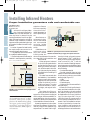
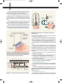
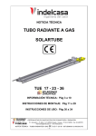
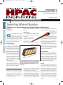
0720_HPAC_MOMF.qxd
2/18/05
1:53 PM
Page 56
www.hpac.com
Selecting Infrared Heaters p. 1
Installing Infrared Heaters p. 2
Operation & Maintenance for Infrared Heaters p. 4
Commissioning Infrared Heaters p. 5
A PENTON PUBLICATION
DESIGN
E Q U I P M E N T
N O T E B O O K
Selecting Infrared Heaters
COMMISSIONING
OPERATION & MAINTENANCE
INSTALLATION
Tubular vs. panel-type gas-fired infrared heaters
By RICK KARG
R.J. Karg Associates
Topsham, Maine
or high air leakage rates because they heat objects,
not the air.
as infrared heaters are very versatile.
They are found in many commercial
facilities, including factories, warehouses, repair garages, aircraft hangers, trasportation
terminals, parking garages, greenhouses, and loading
docks. They are effective for spot or task heating and
also work well for general space heating..
EQUIPMENT TYPES
There are two types of gas infrared heaters available: high intensity (panel type) and low intensity
(tubular type).
High intensity units are square or
rectangular in shape and require adequate dilution
air because they are
unvented. The gas flame heats a ceramic or stainless
G
WHY INFRARED HEAT?
Infrared units heat primarily by radiant heat transfer, similar to the way direct
sunlight heats our bodies. Radiant (infrared) energy travels in straight lines and
is absorbed by any object that is opaque. It
passes through objects and materials that
are transparent, such as air. Their physical
characteristics make infrared heaters a
good choice for heating people (we’re all
opaque) who are working or sitting in areas where there is substantial air movement, such as loading docks or grandstands. Heating the air in these places
would be very inefficient.
When using gas infrared heaters, no
walls are needed for effective zoning.
They are a good choice for buildings
with high ceilings, large volumes of air,
Photos courtesy of Solaronics
A low-intensity tube infrared heater (top) and a high intensity
panel heater (bottom) typically range from 40,000 to 200,000
Btuh inputs. The tube heaters range between 10 and 70 ft in
length, and the panel heaters can provide single- or twostage heating.
Rick Karg is an economist and the president of R.J.
Karg Associates, energy management consultants.
His is a member of the American Society of Heating,
Refrigerating and Air-Conditioning Engineers
(ASHRAE) and the author of “Let the Gas Flow” a
popular handbook on gas-fired equipment. He can
be reached at [email protected].
steel mat, which, in turn, radiates to the objects or
people to be heated. Output from one of these units
can range from 20,000 to 200,000 Btuh.
Panel heaters are best suited where spot heating is
needed in spaces that are not totally enclosed from
outdoor air. This includes stadium seating areas,
covered walkways, golf driving ranges, aircraft hangers, and open loading docks. Strategically placed
high intensity gas infrared heaters are often used today to extend the season of outdoor eating areas.
Low intensity units
are tubular in shape,
the tube either running straight or in a Ushape. The tube is actually part of the
vent system. A parabolic reflector is attached
just a few inches above the horizontal part of the vent
system. Its purpose is to direct the infrared radiation
downward. Because these tubular units are vented to
the outside, they do not require dilution air.
Tubular heaters are ideal for fire stations, farm
buildings, large assembly areas, auto shops, and other
areas that are usually, but not always, closed to the
outdoor air. They work well where there are high
ceilings and large open areas to heat.
INSTALLATION BASICS
When locating and installing infrared heaters, a
few cautions are in order. Be aware of sprinkler system outlets and clearances between the heaters and
stored items. Use with caution where the air is filled
with dust or paint overspray. If the air contains chlorine or chlorinated compounds, the heater’s life span
will be shortened. Next month’s article will review in
depth how and where to install these units.
PAYBACK
If an owner is considering installing either an array of electric infrared heaters or an array of natural
gas infrared heaters, and the gas heaters cost $2,000
more to install, how many years will it take for the
owner to recover the additional cost of the gas units?
Assuming that the operating cost of the gas units is
$500 per year and the operating cost of the electrical
is $1,500 per year, the payback is two years (the additional cost divided by the annual savings,
$2,000/$1,0000 = 2). In other words, the extra
money invested for the gas heaters will be regained in
two years.
1
0720_HPAC_MOMF.qxd
2/18/05
1:53 PM
Page 57
DESIGN
E Q U I P M E N T
N O T E B O O K
Installing Infrared Heaters
COMMISSIONING
OPERATION & MAINTENANCE
INSTALLATION
Proper installation guarantees safe and comfortable use
CAM MARKLOWITZ
MJM Associates Inc.
Englewood, Colo.
explosive or flammaGas supply line
ble fumes, especially
ast month, the sizing and selec- those where chloriManual gastion of commercial, gas-fired in- nated, halogenated, or
shutoff valve
Ground joint union
frared units was discussed. An- acidic vapors are preswith brass seat
other key factor in determining the ent.
Gas
correct type and size of a unit for an appli• Manufacturer re- supply
line
cation is to examine how the unit will be quirements for clearTo controls
installed. Proper installation is at least as ance to combustibles
Plugged 1/8-in. NPT
3-in. min.
important as sizing and selecting the type and recommended
test gauge connection
of infrared unit heater to be used in an ap- mounting heights
plication.
must be adhered to
Sediment trap
A number of general infrared installa- strictly.
tion requirements are common to all
• Installations must
commercial, gas-fired equipment:
conform not only to FIGURE 2.2 A ground joint union and manual shutoff valve
• The installation work must be done local and national should be installed in the gas supply line adjacent to the unit.
by a qualified installation agency.
building codes, but
• Gas-fired equipment should never be also to the requirements of the manufac- intensity infrared units reach temperainstalled in areas exposed to potentially turer described in the installation and tures in excess of 1,700o F, while low-intensity units can produce tube temperaservice manual.
Photos courtesy of Modine Manufacturing
When equipment is selected tures in excess of 1,000 o F near the
for a job, the sizing and selection burner. As a result of these high temperaprocess should produce a plan tures, clearances to combustibles must be
drawing that shows where each strictly adhered to. Be aware of clearances
Minimum clearance to
unit will be located in the build- to the following:
combustible materials
• Combustible materials.
ing. Make sure this plan drawing
• Stacked materials (signs are to be
is available before installing the
Mount
posted in locations with stacked materials
equipment.
height
No matter how neat and clean to indicate the maximum permissible
the installation, if the installation stacking height (Figure 2.1).
Stacking
• Lights.
does not comply with a properly
height
• Sprinkler heads.
designed plan, there will be heat
• Overhead cranes.
related complaints from the
• Objects on lifts (like automobiles inbuilding occupants. The plans
should include location, mount- side repair shops).
Infrared units, like all gas-fired equiping height, and angle of reflecFIGURE 2.1 Post maximum stacking heights below
ment, need clean combustion air to opertors.
infrared heaters.
Next, determine if the sup- ate. High-intensity units and unvented
porting structure is adequate to low-intensity units require a minimum
support the unit and ensure the required air displacement of 4 cfm per 1,000-Btuh
Cam Marklowitz is the vice president of
electric and gas utilities are available. For input for natural gas and 5 cfm per
sales for MJM Associates Inc. in Englevented applications, the unit must be lo- 1,000-Btuh input for propane gas. Not
wood, Colo., which represents 15 manucated so it is vented per the requirements all low-intensity installations can be unfacturers in the HVAC industry, offering
vented. Check the installation-and-servin the installation and service manual.
sales support, product training, applicaOperating temperature is also a factor ice manual provided by the manufaction assistance, and technical support to
that must be considered. High and low- turer. Ventilation and combustion-air
wholesale distributors, OEMs, engineers, intensity infrared units operate at high requirements for both vented and unand contractors.
temperatures. The ceramic tiles in high- vented applications must be adhered to.
L
2
0720_HPAC_MOMF.qxd
2/18/05
1:53 PM
Page 58
E Q U I P M E N T
N O T E B O O K
It is recommended that local authorities be contacted to assure the ventilating system and heater installation are in compliance with any applicable local and/or state codes.
With the plan drawing in hand, now comes the task of
mounting the units. The installer typically encounters, or
should be cognizant of, the following items when installing
both high-intensity and/or low-intensity gas-fired infrared
units:
• Gas or electrical supply should never be used for system
support. The weight of the unit must be borne by the support
structure, which may consist of threaded rods or chains.
• Gas connections and piping must be properly sized for
the total unit capacity. Under-sized piping can lead to underfiring the units, poor performance, and poor combustion.
• Gas supply must never exceed the maximum rating for a
Alternate
supply
locations
Gas supply piping
Certified
flexible gas
connector
Manual valve
Field-supplied gas piping
8-in. min.
Movement
Burner
box
End view
3-in.
min.
Burner
box
Side view
FIGURE 3.3 If local code allows, use flexible gas connectors for
tubular IR heaters.
FIGURE 3.1 Panel-type high intensity units must be installed
between the angles of 10 and 35 degrees from horizontal for the
unit to operate properly. The manifold assembly should always
be located at the lower end of the installation.
12 in.
9 ft, 5 in.
9 ft, 5 in.
unit heater. This is typically 14 in. of water column supply pressure for both natural gas and LP units.
• A ground joint union and manual shutoff valve should be installed in the gas supply line adjacent to unit. Install a gas line sediment trap immediately prior to unit gas controls (Figure 2.2 ).
• Gas connections must be properly sealed and tested for leaks
using a soap solution or an equivalent test. Never use an open
flame.
• Electrical supply voltage should match the voltage on the
unit serial plate. Connections must conform to applicable local
codes and the National Electric Code. Some manufacturers offer
a millivolt, self-energizing control system. These units do not require external power, which is beneficial to minimizing installation cost.
• Electrical supply to the unit is to be protected with a fused
disconnect or circuit breaker.
• Wiring must be sized properly for unit ampacity per the National Electric Code. Wiring polarity must also be correct.
• Gas and electric utilities should not be run above the unit
heaters. This avoids overheating.
In addition to the above items, there are general requirements
common to all types of infrared heater installations.
For high intensity units (Figure 3.1):
24-in. min.
mounting
length
Tube and
reflector hanger
(first tube only)
Suspension
means
Support
bracket
Burner
Burner tube
Reflector
Clamp
Radiant
tube
Baffle
Tube and
reflector hanger
• Units can be hung with a threaded rod where code allows.
Chain-mounting kits provide an easy means for suspending the
unit heaters.
• Units must be installed between the angles of 10 and 35 degrees from horizontal for the unit to operate properly. The manifold assembly should always be located at the lower end of the installation (Figure 3.1).
For low-intensity units (Figure 3.2):
FIGURE 3.2 Low-intensity, tubular infrared-heater installation.
• Flexible mounting should be used for low-intensity tube
heaters to allow for expansion and contraction of the tube sys-
3
0720_HPAC_MOMF.qxd
2/18/05
1:53 PM
Page 59
E Q U I P M E N T
N O T E B O O K
tem. Most manufacturers provide chain-mounting kits for
this purpose.
• Low-intensity units are installed burner box first; then
tube systems are installed one tube at a time, starting from the
burner and working toward the terminating end. While the
tube system should be suspended with flexible mounting, the
burner box should be rigidly mounted to avoid placing strain
on the gas- and electrical-supply connections. If code allows,
the use of flexible gas connectors may be used (Figure 3.3).
• Units must be installed in the horizontal plane.
• Low-intensity units must have reflectors along the entire
tube length and must be overlapped by at least 4 in. to accommodate expansion and contraction.
• Units are to be vented as required by the installation and
service manual, paying careful attention to the following:
• Maximum length.
• Maximum number of elbows.
• Using venting material/systems matching the appliance
venting category.
• Pitching the vent and using properly drained drip legs for
removal of condensate.
• Terminating the vent system per the manufacturer requirements.
• Following requirements of the National Fuel Gas Code.
• Outdoor equipment must have weatherized electrical connections.
Before any equipment is put into operation, the unit should
be properly commissioned. This will be a topic for a future article.
CONCLUSION
By following a properly designed gas-fired infrared unit
heater layout, along with installing this unit per the guidelines
found above, you should be provided with an easy, cost-effective
means of heating a number of applications. Good literature exists to help you make the right decisions. I recommend the “Infrared Design and Engineering Guide.” (LIT # 9-200 available
at modine.com/publications) There also is a wealth of valuable
information from manufacturers’ websites.
For previous Equipment Notebook
articles, visit www.hpac.com.
Solutions for Infrared Heaters
Poor installation is usually the root cause of problems
M
hose into the inlet of each venturi tube.
Burner orifice. Gas orifices are to be
cleaned using drill sizes indicated in the
operation and maintenance manual supplied with the equipment. Remove the
burner orifice and then clean and re-install it on the heater manifold. The pilot
orifice should also be cleaned.
Combustion air blower (low intensity
units). Combustion air blower motors are
OPERATION & MAINTENANCE
COMMISSIONING
typically permanently lubricated, requiring no additional lubrication. Refer to
the operation and maintenance manual
for details. An air-restrictor plate (Photo
A) sized for the appropriate fuel type and
burner input is installed by the factory
and must not be field-adjusted.
Electrical wiring. The electrical wiring
should be checked annually for loose
connections or deteriorated insulation. If
the application is especially dirty, periodically clean the thermostat contacts.
Gas piping and controls. The gas valves
and piping should be checked annually
INSTALLATION
how long the unit is operated. Refer to
the recommendations and service interany infrared-performance vals in the operation and maintenance
issues are caused by improper installation, most
often installing the units too low or too Mike Schires is the infrared product manhigh. (Proper installation was covered in ager at Modine. He holds a bachelor’s delast month’s Equipment Notebook article gree in electrical engineering and can be
“Installing Gas-Fired Infrared Heaters.”) reached at [email protected].
Once the product is properly selected and
installed, a preventative maintenance manual provided with the equipment.
Below are procedures that should be
program is the key to long and troubleincluded in any comprehensive prevenfree product life.
Infrared manufacturers include an op- tive maintenance schedule for gas ineration and maintenance manual with frared heaters:
Burner assembly. Disconnect all elecevery unit. If there is a transfer of ownership, the manual should be left with the trical power to the heater and close the
gas supply valve installed adjacent to the
new owner.
A qualified gas-service technician heater. With an air hose regulated to 15
should service all heating equipment be- psig maximum, blow off any dust and
fore each heating season to ensure proper dirt that has accumulated on the heater.
operation. Some items may require more For high intensity, this includes blowing
frequent service based on the environ- across the ceramic burner (not directly at
ment in which the unit is installed and the ceramic burner). Do not insert the air
DESIGN
By MIKE SCHIRES
Modine Manufacturing Co.
Racine, Wis.
4
0720_HPAC_MOMF.qxd
2/18/05
1:53 PM
Page 60
E Q U I P M E N T
N O T E B O O K
Photos courtesy of Modine Manufacturing
for general cleanliness and tightness. The thermostat should be cycled
and gas controls checked to ensure that the unit is operating properly.
Refer to the sequence of operation in the operation and maintenance
manual shipped with the unit. Some manufacturers include diagnostic
LEDs on the unit to make this check easier.
Troubleshooting . Most manufacturers provide troubleshooting
guides to make problem diagnosis quicker and easier. Some are setup in
a “Trouble–Possible Cause–Possible Remedy” matrix, which can ease
the troubleshooting process.
Do not attempt to re-use any mechanical or electrical components
that were exposed to water. They must be replaced with a factory-approved component.
When servicing or repairing infrared equipment, use only factoryapproved service replacement parts. A complete replacement-parts list
can be obtained by contacting the manufacturer. Refer to the rating
plate on the unit for complete unit model number, serial number, and
company contact information.
PHOTO A. Infrared burner enclosure panel and air
restrictor plate.
For previous Equipment Notebook
articles, visit www.hpac.com.
Commissioning Infrared Heaters
A checklist every installer of gas-fired IR heaters should use
tion air and ventilation is supplied to the
space as specified in the operation and
maintenance manual.
ver the last few editions of
❏ Perform a visual inspection of the
HPAC Engineering, we have
unit to make sure no damage has occurred
discussed the selection, induring installation.
stallation, and servicing of gas-fired in❏ Re-check the gas supply pressure. The
frared heaters. This month we tackle the
inlet pressure for natural gas is typically 5 to
subject of commissioning. The
7-in w.c. for
proper commissioning of an
low intensity
infrared installation ensures
and 7 to 14that once an installer leaves the
in. w.c. for
job site, they will not be called
high intenback.
sity. For
Infrared manufacturers inpropane, the
clude an operation and maintepressure is
nance manual with every unit.
typically 12
This manual includes start-up
to 14-in.
procedures recommended by
w.c. for low
the manufacturer and should
intensity
be referred to during commisand 11 to
Photos courtesy of Modine Manufacturing
sioning. It is crucial that all FIGURE 5.1
14-in. w.c.
start-up and adjustment procedures are
for high inserial plate. Verify that all wiring is secure tensity. Refer to the operation and mainteperformed by a qualified service agency.
and properly protected. Trace circuits to nance manual for the manufacturer’s recensure the unit has been wired according ommendations. The gas supply pressure
Mike Schires is the infrared product man- to the wiring diagram.
must never exceed 14-in w.c. If it does, a
ager at Modine. He holds a bachelor’s de❏ If utilizing indoor air for combus- gas pressure regulator needs to be added
gree in electrical engineering and can be tion and/or the unit is in an unvented in- upstream of the combination gas valve.
reached at [email protected]. stallation area, ensure adequate combus❏ Open the field-installed manual shutBy MIKE SCHIRES
Modine Manufacturing Co.
Racine, Wis.
COMMISSIONING
OPERATION & MAINTENANCE
INSTALLATION
DESIGN
O
START-UP PROCEDURE CHECKLIST
❏ Start by turning off power to the
unit at the disconnect switch. Check that
fuses or circuit breakers are in place and
sized correctly. Turn all hand gas valves to
the “OFF” position.
❏ Next, check that the supply voltage
matches the supply voltage listed on the
5
0720_HPAC_MOMF.qxd
2/18/05
1:53 PM
Page 61
E Q U I P M E N T
N O T E B O O K
COMMISSIONING
If the heater being commissioned is a low-intensity, vented
unit, use the following steps to verify the venting system is adequately sized.
❏ Inspect the venting system for proper size and horizontal
pitch as required in the National Fuel Gas Code and the instructions in the operation and maintenance manual. Determine there is no blockage or restriction, leakage, corrosion and
other deficiencies that could cause an unsafe condition.
❏ As far as practical, close all building doors and windows
and all doors between the space in which the unit(s) connected
to the venting system are located and other spaces of the building. Turn on all exhaust fans to their maximum speeds. Do not
operate a summer exhaust fan.
❏ Place the unit being inspected in operation. Adjust thermostat so that the unit will operate continuously.
❏ After it has been determined that each unit connected to
the venting system properly vents when tested as outlined
above, return doors, windows, exhaust fans, and any other gasburning units to their previous condition.
❏ If improper venting is observed during any of the above
tests, the venting system must be corrected. See the operation
and maintenance manual for the manufacturer’s recommendations.
By following the equipment manufacturer’s commissioning
procedure, you should be assured trouble-free equipment operation, reduced maintenance costs and, most importantly, customer satisfaction.
Articles printed in HPAC July - Oct. 2004.
OPERATION & MAINTENANCE
The gas pressure regulator (integral to the combination gas
control) is adjusted at the factory for average gas conditions. It
is important that gas be supplied to the heater in accordance
with the input rating on the serial plate. Actual input should be
checked and necessary adjustments made after the heater is installed. Over-firing, a result of too high an input, reduces the
life of the unit and increases maintenance. Under no circumstances should the input exceed that shown on the serial plate.
Measuring the manifold pressure is done at the manifold pressure tap on the main gas valve on the heater, as shown in Figure
5.1.
To adjust the manifold pressure:
1. Adjust the main gas pressure regulator spring to achieve
the proper manifold pressure.
2. Move the field-installed manual shut-off valve to the
"OFF" position.
3. Remove the 1⁄8-in. pipe plug-in manifold pressure tap in
the combination gas control and attach a 12-in.-high U-tubetype water manometer.
4. Move the field-installed manual shut-off valve to the
“ON” position.
5. Create a call for heat from the thermostat, check the
manometer reading and adjust pressure per manufacturer instructions as required.
VENTING CHECKLIST
INSTALLATION
MAIN BURNER ADJUSTMENT
6. After adjustment, move the field-installed manual shut-off
valve to the "OFF" position and replace the 1⁄8-in. pipe plug.
7. After the plug is in place, move the shut-off valve back to
the “ON” position and re-check pipe plugs for gas leaks with a
soap solution. Never use a flame to check for leaks.
DESIGN
off valve and turn the power "ON".
❏ Make certain the gas line is purged of air prior to attempting
to operate the unit. Follow the procedure on the heater’s lighting
instruction label to put the heater into operation.
❏ For units equipped with a pilot, check the pilot flame length
and adjust as necessary per the manufacturer’s instructions.
❏ Check to make sure the main gas valve opens upon a call for
heat from the thermostat.
❏ Check to ensure the gas controls sequence properly.
Copyright © 2004 by Penton Media, Inc.
Modine Manufacturing Company
1500 DeKoven Avenue
Racine, WI 53403-2552
Ph: 800.828.4328
Fax: 262.636.1424
Modine LIT # 76-117
6