1
OW
Fli
��
HEWLETT
PACKARD
HP 7475A
Graphics Plotter
-
-
.,
OPERATION
AND
IN TERCONNECTION
MANUAL
HP 7475A
Graphics
Plotter
Getting Help
Hewlett-Packard has support services available to help you in case you
have a problem with your HP 7475A graphics plotter. Following are
suggestions of places to turn for this support.
Before you call for customer support, make sure you do the following.
1.
Review the I've Done Evertking You've Said and It Still Doesn't
Work ... section of Chapter 3 in this Operation and Interconnec·
tion Manual.
2.
Perform the built·in Demonstration Plot/Confidence Test in
Chapter l.
3.
Make sure you are using the correct interface cable and dip switch
settings, as explained in Chapter 3 and Appendix A.
4.
Check with your software vendor for help.
Your Dealer
If you still have difficulty, begin by contacting the person from whom
you purchased your HP 7475A graphics plotter. Your sales representa·
tive is familiar with your needs, equipment and software and should be
able to provide you with the information you want.
HP 7475A Graphics Plotter Customer Assist
If you don't get the answer to your questions from your .dealer or sales
representative, Hewlett-Packard has an HP 7475A Graphics Plotter
Customer Assist service available to you. The HP 7475A Assist staff
can provide you with help by answering questions on topics such as
setting up your plotter and computer, and can help you find third party
software solutions for your special plotting needs.
GEITING HELP
ill
When you call the HP 7475A Assist group, please have the following
information available to help us answer your questions more quickly.
•
•
Identify what computer you are using.
Identify any special equipment or software you are using (for
example, spoolers, networks, switchboxes, modems or special soft·
ware drivers).
___ __
___
•
____ _ ______
_
_ ____ _____
__
_
Identify what cable you are using (by part number) and where you
purchased it.
________
_____ _______
___
•
Identify the type of interface option on your plotter (RS·232·C or
HP·IB).
_ _______
•
_
__
_
____
___ ____
___
__________
_
_
_
_
Identify the software name and version you are currently using.
__
The HP 7475A Assist service is available from 7 am - 4 pm (Mountain
Standard Time), Monday through Friday.
(208) 323-2551
Should the plotter require service, please refer to the last section
Chapter 1 for shipping instructions.
IV
GEITING HELP
ID
Table of Contents
Chapter 1: Owner's Information ...............................
1·1
Introduction ................................................
1·1
Understanding Manual Conventions .........................
1·2
Initial Inspection and Accessories Inventory ..................
1·2
Accessories Supplied ......................................
1-3
Accessories Available .....................................
1-3
Input Power Requirements .................... .. .... ........
1·4
Power Options ............................................
1-4
Line V oltage Selection........ ............................ .
14
Fuse Protection ...........................................
1·5
Grounding Requirements ..................................
1·5
Power Cord ... ... ........... ............... .... .. .. ...... .
1·5
Operator Maintenance ......................................
1·7
General Cleaning .........................................
1·7
Pen Carousel Cleaning ....................................
1·8
Shipment ..................................................
HI
Chapter 2: Plotter Operation ..................................
2·1
Introduction ................................................
2-1
Major Feature Locations ....................................
2·1
Introduction to Programming Languages.. ... ......... .... ...
2-2
What Is a Program? .. .... ... ....... .... ........... ..... ...
2·2
What Programming Languages Do I Use? ..................
2·3
AGL (A Graphics Language) ..............................
2-3
HP-GL (Hewlett·Packard Graphics Language) ..............
2·3
Introduction to the Plotter Coordinate System ................
2·4
Coordinate System Orientation ............................
2-5
Hard·Clip Limits.. ..... .... ...... ... ......... .... .. .... .. .
2-5
The Scaling Points PI and P2 .............................
2·7
HP·GL Scaling ...........................................
2·7
AGL Scaling .............................................
2·8
Setting the Scaling Points .................................
2-9
Preparing Equal·Sized Plots ...............................
2-9,
Squeezing the Scaling Area ''''''.............. .. ... .... ... 2-10
Rotating the Coordinate System ...........................
2-12
Controls and Indicators and Their Functions .................
2-14
Front Panel ..............................................
2·16
Rear
Panel
................. .................. ... .
.
.
.
.
.
.
.
. 2·20
'fABLE OF CONTENTS
v
Table of Contents (Continued)
Chap ter 2:
Plotter Operation (Continued)
Option 001 (RS-232-C/CCITT V.24)
.
.
.
.
.
.
.
.
. .
.
. .
.
•
.
... .... 2·21
Option 002 (HP·IB) ...................................... 2·23
Setting Up the Plotter ....................................... 2-24
Choosing the Correct Pen and Medium ..................... 2·25
Loading Pens and the Carousel ............................ 2·25
Loading the Plotting Medium .............................. 2·26
Turning On the Power .................................... 2-28
TheDemonstration Plot/Confidence Test .
.
.
. .
.
. .
•
•
•
.
.. ... .... 2·31
Chapter 3: Plotterlnterconnection .............................
Introduction
.
.
.
.
.
.
.
.
.
.
.
.
.
.
.
.
.
.
.
.
.
.
.
.
.
.
.
.
.
.
.
.
.
.
.
.
.
.
.
.
.
.
.
.
.
.
.
.
If Your Computer Isn't Listed ................................
3·1
3-1
3·1
If Your System Configuration IsDifferent From the
One Listed ...............................................
3-2
If the InterconnectionDoesn't Work........................ ..
3-2
If You Ate Using a Graphics Software Package ...............
3-3
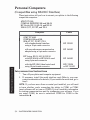
Personal Computers (Compatibles using RS-232-C Interface)
3-4
(AT&T PC 6300
COMPAQ*DESKPRO*�and�/�
HP V ectra, ES/12, QS/16, and RS/20
IBM* AT, PC, PC/XT, and PS/2)
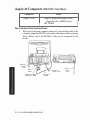
Interconnection Instructions ...............................
34
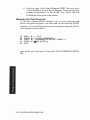
Testing Communication without BASIC . ... ... ... ... .... ...
3·5
Testing Communication with BASIC . ....... .... ..... ......
3-6
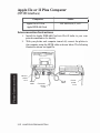
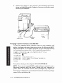
Apple* IIe or II Plus Computer (RS·232·C Interface) ...........
3·7
Interconnection Instructions ............................ ...
3-7
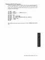
Running the Test Program ................................
3·9
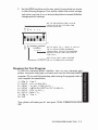
Apple lIe or 1I Plus Computer (HP·IB Interface) ............... 3-10
Interconnection Instructions ............................... 3-10
Running the Test Program ................................ 3-11
Apple /11 Computer (RS-232·C Interface)
.
.
.
.
.
•
.
.
.
.
.
.
.
.
.
.
.
.
.
.
.
.
3-13
Interconnection Instructions ............................... 3·12
Running the Test Program ................................ 3·14
·COMPAQ is a registered trademark of Compaq Computer Corporation.
·DESKPRO is a registered trademark of Compaq Computer Corporation.
·IBM is a registered trademark of International Business Machines Corporation.
·Apple is a registered trademark of Apple Computer, Inc.
V1
TABLE OF CONTEN'I'S
Table of Contents (Continued)
Chapter 3 : Plotter Interconnection (Continued)
Apple Macintosh'/Macintosh Plus/ll/SE
(RS-23 2-C Interface)
.
.
.
.
.
.
.
.
.
.
.
.
.
.
.
.
.
.
.
.
.
.
.
.
.
.
.
.
•
.
.
.
.
.
.
.
.
.
.
3-15
Interconnection Instructions ............. ... ......... ...... 3 ·15
Testing Communication with BASIC ........... .. .... .. .... 3 -16
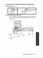
Commodore Amiga' Personal Computers (Serial Interface) . .... 3 -17
Interconnection Instructions ............................... 3 ·17
V erifying Communication
.
.
.
.
.
.
.
.
.
.
.
.
.
.
.
.
.
.
.
.
.
•
•
.
.
.
.
.
.
.
.
.
.
3-19
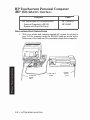
HP Series 200 Personal Technical Computer
(HP-I B Interface) ......................................... 3 -20
Interconnection Instructions
.
.
.
.
.
.
.
.
.
.
.
.
.
.
.
.
.
.
.
•
•
.
.
.
.
.
.
.
.
.
.
3 -20
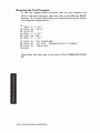
Running the TestProgram .................. .... .. .. ... ... 3 -21
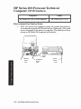
HP Touchscreen Personal Computer (HP 150)
(RS-23 2-C Interface) .................. ..................... 3 ·22
Interconnection Instructions
.
.
.
.
.
.
.
.
.
.
.
.
.
.
.
.
.
.
•
•
.
.
.
.
.
.
.
.
.
.
.
3 -22
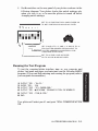
Running the Test Program ................................ 3 -24
HP Touchscreen Personal Computer (HP 150 )
(HP-IB Interface) ... ...................................... 3 ·25
Interconnection Instructions ............................... 3 ·25
Running the Test Program ................................ 3 -26
Chapter 4: Selecting Media, Pens, and Ink ......... .. ... .......
What Kind of Output Do You Need?
.
.
.
.
.
.
.
.
.
.
.
•
.
.
.
.
.
.
.
.
.
.
•
.
.
.
4 -1
4 -1
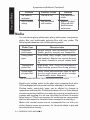
Understanding Media ... ....................................
4 -2
Chart Paper .... ... .......................................
4 -2
Glossy Presentation Paper .. ......... .............. ........
4 -2
Overhead Transparency Film ...... .. .............. ..... ...
4 -3
Double-Matte Polyester Film
4 -3
.
.
.
.
.
.
.
.
.
.
.
.
.
.
.
.
.
.
.
.
.
.
.
.
.
.
.
.
.
.
.
Understanding Pens and Inks ...............................
4 -3
Fiber-TipPens ............................................
4 -4
Drafting Pens ............ ................................
4 -4
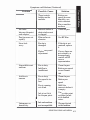
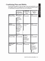
Combining Pens and Media .................................
4 -7
Purchasing Supplies .. ................................ ......
4-8
Appendix A: RS-232-C/CCITT V.24 Interface
Information
.
.
.
.
.
.
.
.
.
.
.
.
.
.
.
.
.
.
.
.
.
.
.
.
.
.
.
.
.
.
.
.
.
.
.
.
.
.
.
.
.
.
.
.
.
.
.
.
A-I
RS-23 2-C Pin Allocations . .................................. .
A-I
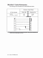
RS-23 2-C Cable Schematics ..................................
A-2
'Macinto.h is a regi.t.red trademark of Apple Compuw, Inc.
·Amiga is a registered trademark of Commodore-Amiga, Inc.
TABLE OF CONTENTS
VU
,
.
f :&
'i
'
. I
...";::� .... ...
.',';;.�.",.
.,. ..
,',
#'V'
oil
J
Chapter
1
Owner's Information
Introduction
This manual contains general information to familiarize you with the
capabilities and operation of the HP 7475A Option 001 and Option 002
Graphics Plotters. The Option 001 plotter is equipped with the R.S-232-CI
CCITT V.24 Interface. The Option 002 plotter is equipped with the
Hewlett-Packard Interface Bus (HP·IB), which conforms to ANSI/IEEE
488·1978 specifications. Both interface options use the Hewlett-Packard
Graphics Language (HP·GL) for control of plotter graphics capabilities.
Unless specifically noted, all information in this manual pertains to
both interface options.
NOTE: Ail information in this manual for the RS-232-C interface
applies equally to the CCITT V.24 interface. For purposes of simplicity,
both are referred to as RS·232-C.•
This manual is designed to show you how to operate, but not program,
the plotter. The information given will enable you to verify that your
plotter has not been damaged in shipment and that it is compatible
with the power available in your geographic area. It explains each
control and indicator, the plotter's coordinate system, and how to set up
the plotter and run the built·in demonstration plot.
Additional information is given to show you how to connect the plotter
with many commonly used computers.
Ail plotters are shipped with this manual and a Reference Card (part
No. 07475·90004). The Reference Card contains a summary of HP·GL
and device control instructions, plotter default conditions, and a list of
error numbers and their meanings. The plotter is supported on a
number of HP computer systems using higher level graphics support
than HP·GL. In most cases, high level graphics support is available
through graphics programming ROMs or software, each of which is
supported with a comprehensive user's manual which will answer most
of your questions related to programming. Contact your HP sales
representative or dealer regarding high level graphics support available
with your HP computer.
OWNER'S INFORMATION
1·1
Understanding Manual Conventions
Before reading this manual, you should understand the meaning of
type styles and number representation used in text. Words typed in
small, boldface type are either buttons, switches, or words actually
found on the plotter. Numbers are shown using SI (International Sys
tem of Units) standards. Numbers with more than four digits are
placed in groups of three, separated by a space instead of commas,
counting both to the left and right of the decimal point (54 321.123 45).
Initial Inspection and Accessories
Inventory
The individual parts of your plotter were thoroughly inspected before
the unit was shipped to you, and the instrument should be in good
operating order. Carefully inspect the plotter and accessories for any
physical damage sustained in transit. Notify the nearest HP Sales and
Support Office or authorized HP dealer and file a claim with the carrier
if the unit is received in a damaged condition.
Please check to ensure that you have received all of the items that
should accompany the plotter. Refer to the table of Accessories Supplied
and check that all accessories are present. If you have any difficulties
with the plotter, if it is not operating properly, or if accessories are
missing, contact the nearest HP Sales and Support Office or authorized
HP dealer.
Retain the original packing materials and carton. If the plotter must be
shipped, this will save having to order new packing materials and a
carton from HP.
1-2 OWNER'S INFORMATION
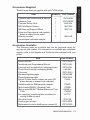
Accessories Supplied
The following items are supplied with each 7475A plotter:
Item
Quantity
Part Number
Operation and Interconnection Manual
1
07475·90002
Reference Card
1
07475-90004
Customer Survey Card
1
5958-2664
HP Field Repair Centers
1
5957-2658
HP Sales and Support Offices
1
5955-7441
Power cord (appropriate cord supplied,
based on origin of sales order)
1
Fiber·tip carousel
1
5061·5080
Assorted pen and media samples
Accessories Available
The following items are available and can be purchased using the
appropriate part number. For information on available pen and media
supplies, refer to the Supplies and Cables brochure shipped with your
plotter.
Part Number
Item
Service Manual
07475-90000
Interfacing and Programming Manual
07475-90001
Carrying case (not suitable for shipping plotter)
07475-60001
1540-0061
Transit case (suitable for shipping plotter)
Dust cover
07475-60010
Standard digitizing sight
09872-60066
Slanted digitizing sight
07585-60191
Special Y-cable (used to connect an option 001
plotter between a terminal and computer)
17455A
Interface cable for IBM personal computer
17255D
Male-to-male RS·232·C Standard Cable
17355M
Male-to·male RS-232-C Modem Eliminator Type
Cable
Pen organizer (a smoked plastic container for
storing 20 fiber·tip pens)
13242G or
17255M
92177V
8710-1386
Grit wheel brush
Drafting pen carousel
07470-60030
Replacement boots for drafting pen carousel (2)
07475-60038
OWNER'S INFORMATION
1·3
Input Power Requirements
WARNING
To prevent operator injury or damage to the plotter,
verify that the line voltage setting and fuse protection
are correct BEFORE connecting the line power . Also
ensure the line power cord is connected to a line power
outlet that is provided with a protective earth ground
contact.
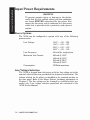
Power Options
The 7475A can be configured to operate with any of the following
power sources:
Line Voltage:
100V - +5%, -100/0
120V - +5%, -100/0
220V - +5%, -10%
240V - +5%, -10%
Line Frequency:
48to 66 Hz, single phase
Maximum Line Current:
480mA@100V
400mA@120V
220mA@220V
200mA@240V
Consumption:
35 Watts maximum
Line Voltage Selection
The 7475Ais shipped from the factory with the line voltage set to the
nominal value for the area specified as the shipment's destination. The
voltage selected for the plotter is identified in the recessed window on
the rear panel. Refer to the Major Feature Locations photograph in
Chapter 2. The line voltage can be changed by qualified service per
sonnel only. Line voltage selection procedures are contained in the
7475AService Manual .
1-4
OWNER'S INFORMATION
Fuse Protection
WARNING
To avoid the possibility of injury, disconnect the ac
power cord before installing or replacing a fuse.
The 7475A is factory equipped with a fuse appropriate to the factory-set
line voltage. The selected line voltage and the corresponding fuse rat·
ing is shown in the recessed window on the rear panel. To change or
inspect the line fuse, turn the fuse holder on the rear panel in the direc·
tion of the arrow (counterclockwise) until the fuse holder releases.
Remove the fuse holder and insert a slo-blo type T fuse which corre
sponds with the voltage setting. Fuse ratings for each voltage setting
are shown below. Place the fuse holder back into the plotter, and turn
the fuse holder clockwise, while pressing in, until the lock engages and
the fuse remains flush with its casing.
Voltage
U.S. Fuse
100 Vor 120V
0.6A T(SB)/125 V
220 Vor 240V
0.3AT(SB)/250V
European Fuse
-
0.3151AT(SB)/250V
NOTE: Fuses and fuse caps appropriate to the plotter shipment desti
nation are installed at the factory. U.S. fuses are '4 X 1% inches and
use HP 2110-0565 fuse caps. European fuses are 5 X 20 millimetres and
use HP 2110-0567 fuse caps.•
Grounding Requirements
To protect operating personnel, the plotter must be properly grounded.
The plotter is equipped with a three-co nductor power cable which, when
connected to an appropriate power outlet, grounds the plotter. To pre
serve this protection feature, do not operate the plotter from a line
power outlet which has no ground connection.
Power Cord
Power cords with different plugs are available for the plotter. The cord
packaged with each plotter depends upon its destination. The power
cords supplied by HP have a standard female plug which mates with
the power-input socket in the plotter. The polarities of the male plugs
shown in the accompanying chart are matched to the line power outlets
used in the indicated areas. If the plotter has the wrong power cord for
the area, please contact your local HP Sales and Support Office or
authorized HP dealer.
OWNER'S INFORMATION
1-5
Option No.
BS 1363A
N
=
HP Part Number 8120-1351; 250 V,13 A,I '"
plug rating. For use in United Kingdom.
900
HP Part Number 8120-1369; 250 V, 10 A,I '"
901
l
=
,
o
ASC1l2
plug rating. For use in Australia, New
Zealand.
HP Part Number 8120-1689; 250 V, 10/16 A,
4> plug rating. For use in East and West
Europe, Saudi Arabia, Egypt.
902
NEMA5-15P
HP Part Number 8120-1378; 125 V,IS A, 1 '"
903
ltJ
�
@
plug rating. For use in Canada, Japan,
Mexico, Philippines, Taiwan, UL approved
in United States.
CEE 7-VlI
1
N
l
o
0
HP Part Number 8120-0698; 250 V,IS A, 1 '"
plug rating. UL approved in United Stares.
904
SEV 1011
HP Part Number 8120-2104; 250 V,10 A, 1 '"
plug rating. For use in Switzerland.
906
DHCK-107
HP Part Number 8120-2956; 250 V,10 A,I '"
plug rating. For use in Denmark.
912
NEMA6-15P
o
N
o
l
0
NOTE: All plugs
are viewed
from connector end.
L = Line or Active Conductor (also called "live" or "hot'')
N = Neutral or Identified Conductor
E = Earth or Safety Ground
Power Cord Configurations
1·6 OWNER'S INFORMATION
Operator Maintenance
There are no operator·serviceable parts inside the HP 7475A plotter.
Maintenance which can be performed by the operator is limited to
maintaining the appearance of the plotter. All other maintenance must
be performed by qualified service personneL Refer to the Shipment
paragraph for instructions on how to obtain servicing assistance.
General Cleaning
WARNING
Disconnect the plotter from the power source
performing any maintenance. DO NOT allow
run onto electrical components and circuits or
openings in the enclosure as this may create
hazard.
prior to
water to
through
a shock
CAUTION
Do not attempt to clean the grit wheels. Cleaning solu·
tions may dissolve the adhesive which secures the grit
particles to the wheels.
Thorough cleaning should be performed periodically. Cleaning intervals
are determined by the type of operation, local air contamination, and
climatic conditions. Cleaning procedures should include the following:
L
Blow away dust accumulation in the grit wheel area, with corn·
pressed air, if available, or brush away dust using the grit wheel
brush (Part No. 8710·1386).
2.
Clean the outer surface of the plotter with a damp sponge or cloth.
Use a mild cleaning solution if necessary, followed by water to
rinse off any residue. Wipe dry after cleaning.
NOTE: To prevent scratching, do not use abrasive cleaners on the
plastic carriage cover or on the outer surface of the plotter. In addition,
some "mild" detergents might cause the paint to blister because they
contain chemicals that strip water·based paints. For this reason, it is
recommended that you use a soft cloth dampened with a 50-50 solution
of isopropyl alcohol and water. Then rinse off any residue with water
and dry with a soft, lint-free cloth.•
Compulf'I
M\I�"\Orn
OWNER'S INFORMATION
1·7
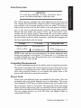
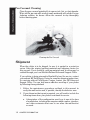
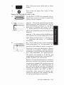
Pen Carousel Cleaning
Clean the pen carousel periodically to remove ink, lint, or dust deposits.
Wipe out the pen cap with a cotton swab moistened with alcohol or pen
cleaning solution, as shown. Allow the carousel to dry thoroughly
before inserting pens.
---
Cleaning the Pen Carousel
Shipment
When the plotter is to be shipped, be sure it is packed in a protective
carton. Keep the original packing materials and shipping carton for
this purpose. If not available, packing materials and a carton may be
ordered through your local Hewlett-Packard Sales and Support Office.
If your plotter is being returned to Hewlett-Packard for service, contact
your nearest HP Field Repair Center for complete shipping instructions.
In countries without Field Repair Centers, contact your HP Sales and
Support Office. You can help assure effective servicing of your plotter
by following these guidelines:
1.
Follow the maintenance procedures outlined in this manual to
verify the malfunction and, if possible, identify the defective area.
2.
If you determine that repair is required, you will need to include the
following items when your plotter is returned for service.
a. A description of the configuration exactly as it was at the time
of malfunction, including the computer model number, interface,
and other accessories that were in use when the malfunction
occurred.
l� OWNER'S INFORMATION
b.
A brief description o f malfunction symptoms for serVICe
personnel.
c.
Plots or any other materials that help illustrate the problem area.
d.
If purchased through an HP dealer, a copy of the sales slip or
other proof of purchase to establish the warranty coverage period.
e.
Serial number of your plotter (located on rear panel).
3.
Include your name and address. Also include the telephone number
where you may be reached during the day.
4.
Do not include the power cord or other operating accessories with
your plotter, unless the problem relates to an accessory.
OWNER'S INFORMATION
1-9
Chapter
2
Plotter Operation
Introduction
In this chapter you will learn about programming languages, the
functions of each control and indicator, the plotter's coordinate system,
and how to rotate the coordinate system. You will also learn how to
load pens and paper and hQw to determine that the plotter is functional.
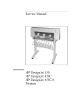
Major Feature Locations
The following illustration shows the locations of the major operating
features. The pen holder is shown at ite power-up position near the
right limit of the drawing range. The pen carousel is located on the left
side of the plotter and holds up to six pens, which can be accessed by
the pen holder.
The pinch wheels and grit.covered drive wheels that move the paper
back and forth across the platen are spaced to accommodate either
ANSI A and B or ISO A4 and A3 size media. The paper loading lever
which raises and lowers the pinch wheels is located on the right side of
the platen.
The operating controls and indicators are grouped on the front panel at
the right side of the plotter. Configuration and interface controls are
located on the rear panel. The controls are explained in detail later in
this chapter.
PW'ITER OPERATION
2-1
PAPER
1
PEN
CAROUSEL
PEN
LEVER
lI1Innl:mu::
"'7- '
REAR
PANEL
(TYPICAL)
'
,UIIII1II1I U 1111111111 till III IIII I� tllltl
.\
SERIAL
NUMBER
.� T
LINE VOLTAGE!
FUSE RATING
LABEL
w
'
-
i
LINE
POWER
SOCKET
Major Feature Locations
Introduction to Programming Languages
What
Is a Program?
A program is an organized set of instructions that tells your computer
and plotter to accomplish certain tasks. There are two types of programs
that you can use to generate the input data for your graphics plots;
prepackaged software programs and user-written software programs.
Prepackaged software programs are easy to use and usually do not
2-2
PL01'1'ER OPERATION
require that you have a programming background. The manual sup
plied with your prepackaged software contains complete instructions
for its use. If prepackaged software is not available for your applica
tion, it will be necessary to learn the programming languages that the
computer and plotter understand.
What Programming Languages Do I Use?
Although there are many programming languages, it is probable that
your computer understands BASIC (Beginner's All·purpose Symbolic
Instruction Code). BASIC is a common programming language that is
used to tell your computer what to do. It uses statements that resemble
English, is easy to use, and enables you to perform many complex
operations. These operations include computation, data base manage
ment, and conditional evaluation of data to control program branch
ing. BASIC also includes input and output statements which allow
your computer to communicate with the plotter. Output statements are
used to send Hp·GL instructions to the plotter. Input statements are
used to read responses from the plotter. If you are new to BASIC
programming and want to learn, your computer store can probably
supply a good BASIC programming manuaL If you are using a Hewlett·
Packard computer, your com puter programming manual contains com
plete details of the BASIC language version that it implements.
In addition to the computer language, you must also understand the
plotter's language (HP·GL) or a high·level graphics programming lan·
guage, such as AG 1..
AGL (A Graphics Language)
AGL is implemented on Hewlett·Packard computers to simplify graphics
plotting. AGL statements are an extension of the BASIC programming
language. They consist of English words that are usually followed by
numeric parameters. These statements describe their graphics plotting
function and instruct the computer to send HP-GL instructions to the
plotter. One AGL statement often performs a task that would require
several HP-GL instructions to perform. Your HP computer documenta
tion is the source of the information you need to write plotting programs
using AGL statements.
HP-GL (Hewlett-Packard Graphics Language)
HP-GL is the graphics programming language that is actually sent to
and understood by the plotter. HP-GL instructions consist of two-letter
mnemonics that are usually followed by numeric parameters. With the
exception of certain escape sequence instructions which are used for
control of interface functions in an RS-232-C environment, all data
received by the plotter is interpreted as HP-GL instructions. You can
include HP-GL instructions directly in the computer language output
PLOTTER OPERATION
2-3
statements, or you can use AGL statements which the computer encodes
and sends to the plotter as HP-GL instructions. The Interfacing and
Programming Manual contains complete infonnation about handshak·
ing and programming in HP·GL.
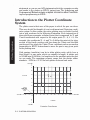
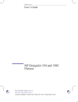
Introduction to the Plotter Coordinate
System
The plotter area is that area of the paper in which the pen can draw.
This area should be thought of as a two-dimensional Cartesian coordi·
nate system. In this system, the entire plotting area is divided (scaled)
into a grid as shown in the following illustration. Each intersection of
these grid lines represents a distinct point that is expressed by X-and
Y·axis coordinates with respect to the origin point (X = 0, Y = 0). For
example, the coordinates X = 4 and Y = 5 define the point at the inter
section of the fourth positive grid line along the X-axis and the fifth
positive grid line along the Y·axis. These coordinate values are used as
parameters in HP-GL instructions to move the pen to any given point
in the plotting area.
Grid spacing (resolution) can be in either plotter units, which have a
fixed length, or user units, which are variable in length. A plotter unit
is 0. 02488 mm ( 0. 00098 in.) in length and is the smallest move the plot
ter can make. The maximum numeric range that the plotter under·
stands is -32768 to +32767 for both plotter units and user units.
+32767
•
•
7
6
5
y ·AXIS
14,5
4
3
�
2
OR IGIN
'
IO.OI
-32768
••
•
-2
-1
1
2
3
4
5
6
-1
-2
•
X-AXIS
•
-32768
Cartesian Coordinates
2·4 'PLO'ITER OPERATION
7
B
9
1 0 ' • • +32767
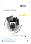
Coordinate System Orientation
The location of the coordinate origin (0 , 0 plotter units) and the orienta
tion of the X· and Y·axis with respect to A and A4 or B and A3 paper
sizes are shown in the following diagrams. Hard-clip limits and the
approximate default locations of scaling points PI and P2 are also
shown. All of these default conditions are determined by the settings of
the US/MET and A4/A3 switches when plotter power is first turned on.
Hard-Clip Limits
The hard-clip limits determine the maximum limits of the pen's motion
and the area within which scaling points PI and P2 can be positioned.
Except for narrow margins which are required by the grit wheel paper
moving technology, the hard-clip limits allow plotting on the entire
paper surface. The following table shows the maximum plotting range,
in plotter units, for aB four paper sizes. Note that the plotting ranges in
the X- and Y-axis are reversed when the 90-degree rotate function is
turned on. Refer to Rotating the Coordinate System in this chapter.
NOTE: The power-up default input window is coincident with the hard
clip limits. The size of the input window can be changed using the HP
GL instruction, lW, to programmatically limit the pen's motion .•
'V HARD-CLlP
I
LIMITS
,
(DEFAUL
L
+y
'+X
I
,
,
,
,
0,0 ORIGIN
Default Orientation of Plotter Coordinate System (AIA4 Paper)
PLOTIER OPERATION
2-5
---------- --- ----..
PI IDEFAULT)
,
I
:
-f
HAAO-CUP
LIMITS ......
,
I
r--+ +Y
+x
(OEFAULT) P2 •
Default Orientation of Plotter Coordinate System (BI A3 Paper)
Maximum Plotting Ranges
Maximum Plotting Range
(Plotter V nits)
Paper Size Settings
Selected
VS/MET
A4/A3
Paper Size
X-Axis
V-Axis
US
A4
A
(8.5 x 11 in.)
0·10365
(257.8 mm/
10.15 in.)
0·7962
(198.1 mm/
0·16640
(413.9 mm/
16.3 in.)
0·10365
(257.8 mm/
10.15 in.)
0-11 040
(274.6 mm/
10.81 in.)
0·7721
US
A3
B
(11 x 17 in.)
MET
A4
A4
(210 X 297 mm)
MET
A3
2·6 PLOTTER OPERATION
A3
(297 X 420 mm)
0·16158
(401.9 mm/
15.82 in.)
7.8 in.)
(192.1 mm/
7.56 in.)
0-11 040
(274.6 mm/
10.81 in.)
The Scaling Points PI and P2
On power-up. the default location of scaling point PI is in the lower-left
corner of AI A4 size paper or in the upper-left corner of BIA3 size paper.
I n each case, the default location of scaling point P2 is in the corner
opposite from Pl. The exact default coordinate locations of scaling
points PI and P2 are shown in the following table, in plotter units, for
the different paper sizes. These default coordinate values define oppo
site corners of a rectangular area that is centered on the associated size
of paper. Regardless of its size, the rectangular area defined by Pl and
P2 will hereafter be referred to as the " Pl ! P2 frame."
Default Coordinate Values for Scaling Points PI and P2
Default Scaling Points (Plotter Units)
Paper
Size
Plx,Ply
P2x,P2y
A
2 50, 59 6
10250,7796
A4
603 ,52 1
1 0 603 , 772 1
B
522 , 259
15722 , 102 59
A3
17 0, 602
15370, 10 602
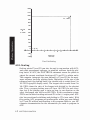
HP-GL Scaling
Scaling points P I and P2 can be used in conjunction with the Hp·GL
instruction, se, to enable you to plot in user units that are convenient
to your application. The size of the user unit is determined by the phys
ical dimensions of the P lIP2 fr ame and by the parameters of the
se instruction. These parameters assign user-unit coordinates to PI
and P2 and divide (scale) the entire plotting area, not just the PlIP2
frame, into a user-unit grid. Grid spacing can be anisotropic (unequal
in X and Y) or isotropic (equal in X and Y) and each axis can have a
different n umber of user units. For example, the HP - GL instruction
SCO , 12,0, 1 000 scales the PI/P2 frame into 1 2 user units in the X-axis,
representing months, and into 1000 user units in the Y-axis, represent
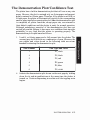
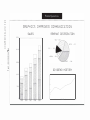
ing total sales in dollars.
Scaling points PI and P2 retain the assigned user-unit values until
scaling is turned off or another se instruction redefines their user-unit
coordinate values. Therefore, the size of a user unit will change with
any change in the distance between PI and P2. This feature allows you
to fit the same plot on any size of paper.
PLOTTER OPERATION
2·7
1200
1100
1000
P2
(12,1000)
900
sOD
700
SALES
$
(V-AXIS)
600
500
400
300
200
100
0
-2
-1
Pl (0,0)
0
1
2
3
4
5
6
7
S
9
10
11
12
13
14
-100
-200
MONTHS
(X-AXIS)
User-Unit Scaling
AGL Scaling
Scaling points PI and P2 can also be used in conjunction with AGL,
and some prepackaged software, to establish software hard·clip plot·
ting limits. In AGL, the PLOTTER IS statement causes the plotter to
output the current coordinate locations of PI and P2, in plotter units.
The computer interprets the area defined by PI and P2 as the maxi·
mum software hard·clip plotting limits. Reg ardless of the size of the
software hard-clip plotting limits, the shortest side is scaled from 0 to
lOO G nUs (graphic display units). The longest side is scaled from 0 to
lOO G nUs times the ratio of the longest side divided by the shortest
side. Thus, a square plotting area will have lOO G nUs in each direc·
tion, but if the plotting area is twice as long in one direction as the
other, the longest side will have 200 G nus. In this coordinate system,
G nus are the default scaling units and P I is the 0, 0 origin point. AGL
also has provisions for defining and plotting in VUB (user units), With
this system, AGL programs can produce plots within any area defined
by PI and P2 without modifications to the program. Refer to your HP
computer documentation for the information you need to program in
AGL.
2-8
PLOITER OPERATION
Setting the Scaling Points
The locations of scaling points PI and P2 can be changed manually
from the front panel or programmatically with the Hp· G L instruction
I P. Refer to the Interfacing and Programming Manual for instructions
on how to set the scaling points programmatically.
The position of P2 can be changed without changing the position of PI.
However, when you move PI, P2 automatically moves so that the X
and V-distances between PI and P2 remain the same. You can-leave P2
in its automatic new position, or you can set a different position for P2.
You can reestablish default positions for PI and P2 by any of the
following methods:
•
power-up initialization,
•
execution of either the Hp·GL instruction, IN, or the instruction I P
without parameters,
•
simultaneously pressing ENTER and VIEW (front-panel reset).
Whenever the plotter is turned on, the following procedure can be used
for manually relocating PI a"d P2.
NOTE: Always set PI first, since P2 moves when PI is moved. •
1.
Using the cursor pushbuttons (arrow pushbuttons), position the
pen at the new location chosen for PI.
2.
Press ENTER simultaneously with P1 to store the new location of PI.
3.
Using the cursor pushbuttons, position the pen at the location
chosen for P2.
4.
Press ENTER simultaneously with P2 to store the new location ofP2.
5.
To check the new points, press Pl, then press P2. The pen should
move to the new PI point, then to the new P2 point.
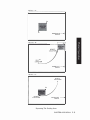
Preparing Equal-Sized Plots
Automatic positioning of P2 as PI is moved can be used advanta
geously in applications such as preparing two equal-sized plots on the
same page. This function is illustrated in the following diagram. Use
the procedure given for setting the scaling points to establish the first
PI/P2 frame. When plotting is completed, set the new position for PI
for the second plot. P2 moves proportionately and automatically estab
lishes an equal-sized PlIP2 frame for the second plot.
PLO'ITER OPERATION
2-9
Preparing Equal-Sized Plots
Squeezing the Scaling Area
When a P lIP2 frame is established within the plotting area, and then
PI is moved so that P2 intersects the hard·clip limits, a new Pl!P2
frame is established at the point of intersection_ This feature is illus
trated as follows:
DETAIL A:
Illustrates the initial PlIP2 frame.
DETAIL B:
Illustrates moving PI to a new position. P2 moves propor
tionately until the hard·clip limit is reached. A t this
poin 1, P2 stops moving with PI and the distance between
PI and P2 changes.
DETAIL C:
Il lustrates moving PI back to its original location. PI
and P2 maintain the relationship established in Detail B,
thus producing a "squeezed" P I /P2 frame.
2-10 PLOTTER OPERATION
DETA I L "A"
'2
.,
HAAD·CLlP'
LIMITS
-�
HAAD-ClIP
LIMITS
-�
DETAIL "8"
.,
DETA I L "C"
OLD Pl
LOCATION
o
'2
NEW Pl
LOCATION
HAAD-CLlP
LIMITS
-�-i
Squeezing The Scaling Area
PLQITER OPERATION
2-11
Rotating the Coordinate System
The plotter coordinate system can be manually rotated 90 degrees from
its default orientation as shown in the following illustrations for AI A4
and BI A3 paper sizes . The rotate function is effective whether plotting
is being done in plotter units or user units .
The rotate function can be manually invoked from the front panel,
using the ENTER + FAST button combination, or programmatically, using
the HP·GL instruction, RO. The only difference is the rotated locations
r-- -
UR
-
I
Pt
_ _ _ _ _ _ _ _ _ _ _ _ _ _ _
I
-
Pt
-
.:..., I
HARD
_ CLIP_ L I M I TS
I
I
&
INPUT
I
I WIN DOW
J
I
�
r--
-pi1
I
I
I
I
Ll (O , O OAIGIN)
.,
I
I
I
I
I
I
:
I
L
r +Y
I
P2 I
oI
+x
_
_
_
_
_
_
_
_
_
_
:
I
_ _ _
LL (0 . 0 ORIGIN)
UR
DEFAULT ORI ENTATION
ROTATED 90 DEGREES
Front-Panel Rotation on AIA4 Size Paper
LL (0 , 0 ORIGIN)
--- fp,
I
I
I
I
-
-
.,
I
- - -
I
I
I
I
I
I
I
1
HARD·
I -- CLl P1
LlMITS
I
&
I
I
X
1
+
L_
UR
I
I
I
,
,
P2 '
_ _ _ _ _ _ _ _ _ _ __ _ _
•
UR
DEFAULT ORIENTATION
-P2'
I
I
+y
I N PUT
WIN DOW
,
I
,
I
P,
� - - - - - - - - - - - - - - -J
Ll (0,0) ORIGIN)
ROTATED 90 DEGREES
Front·Panel Rotation on 81A3 Size Paper
2·12
PLOTIEROPERATION
I
I
I
of PI and P2 and the physical size of the input window. Whether
invoked manually or program matically, rotations are not cumulative,
and the rotate function can only be toggled on or off.
When the 90-degree rotate function is invoked with the ENTER + FAST
buttons, the default input window remains coincident with the hard
clip limits and PI and P2 assume new rotated default coordinate loca
tions inside the hard-clip limits. These new Pl/P2 values are shown in
the following table. Note that the physical location and size of the
PlIP2 frame are not affected by the front-panel rotate function.
Rotated Default Coordinate Values for Scaling Points PI and P2
Rotated Default Scaling Points (Plotter Units)
Paper
Size
Plx,Ply
A
154 , 244
7354 , 10 244
0 , 6 10
7200 , 1 0 6 1 0
B
283 , 934
1 0 283 , 16 134
A3
607 , 797
1 0 607 , 1 5 997
A4
P2x,P2y
When the 90-degree rotate fu nction is invoked with an R090 instruc
tion, PI and P2 retain their current coordinate values and may therefore
be rotated outside the hard·clip limits as shown in the following illus
tration. The default input window is also rotated, but its physical size is
clipped to a square area by the hard-clip limits. Note that the input
window limits programmed pen motion to the window area, but the pen
can still be moved anywhere within the hard-clip limits using the front
panel cursor buttons. The input window can be expanded to the hard
clip limits and PI and P2 can be defaulted to the rotated default coor
dinate values using the HP-GL instructions, IW and lP, without
parameters.
Whether invoked manually or programmatically, the physical size and
location of the hard-clip limits are not affected by the rotate function.
However, the defined lower-left (LL) and upper-right (UR) corners of the
hard-clip limits are rotated to maintain the same relationship with
respect to the 0 , 0 origin point. The coordinate values for UR are deter
mined by paper size and the state of the rotate function; but, the coor
dinate values for LL will always by 0 , 0 regardless of paper size and
the state of the rotate function. The current plotter unit coordinate
values for LL and U R can be obtained by executing the H p·GL instruc
tion, OH.
PLOTIER OPERATION
2-13
UA
- ..
P2 1
Y
c-
I
I
I
I
I
I
I
I
I Pl
�
__ _ _ _
_ __ _ _ _ _
LL (O . O OR1GIN)
\
(0 , 0 ORIGIN)
r-Pl -
-
"
I
+L +x
I
LL
__
I
J
I
I
I
1
+
r
Yi
+x
I
I
I
'-INPUT
WINDOW
I
._
-� UA
-+
'�
----H--
\
HAAD-CLlP
LIMITS AND
INPUT WIN DOW
DEFAULT ORI ENTATION
HARD-ClIP
LIMITS
ROTATED 90 DEGREES
HP-GL R090 Rotation on AIA4 Size Paper
Controls and Indicators and Their
Functions
In addition to the '" LINE power switch and paper loading lever, there
are three categories of operator controls: front panel, configuration, and
interface.
Front-panel controls are used to toggle between either ANSI A and B or
ISO A4 and A3 paper sizes, to manually control pen and paper move
ment, and to change the locations of scaling points PI and P2. They
can also be used for interaction with a running program . This interac
tion includes entry of digitized points, pen selection, and program
suspension without loss of data. All front-panel controls are common to
both Hp·JB and RS·232·C interface options.
Configuration controls consist of two switches on the rear panel. These
switches determine the power-up default paper size, hard-clip limits,
and PI/P2 coordinate values. The switches are common to both HP-IB
and RS·232·C interface options.
Interface controls establish the conditions under which communication
between the plotter and computer will occur. Different interface controls
are required for the HP-IB and RS-232-C interface options.
All operator controls, including the controls which are unique to the
Hp·JB and RS·232·C interface options, are shown in the following illus·
tration. Individual controls and indicators are shown adjacent to their
functional descriptions.
2·14
PLOTTEIl OPERATION
ERROR PCN UfD
"
SIZE.
D D
VIEW
A-I'-O
741!1'" PLOTTER
W�WUY T · ".C;�"\O
FRONT PANEL (2 - 10)
REAR PANEL (14 - 19)
RS-232-C/CCITT V.24
f'
1';;.!
.U
'IIh , 4 ft9-21!!l-c/eCt·'
tTy.U
.. . . . .
. . ..
I
• • • • • • • • • • •
f"
REAR PANEL (20 - 22)
12
HP-IB
Operator Controls
PLO'I�'ER OPERATION
2·15
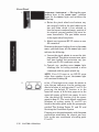
Front Panel
1.
PAPER LOAD I/PAPER HOLD I
Moving the paper
loading lever to the PAPER LOAD I position
turns on the ERROR light and initiates the
-
following:
a. Raises the pinch wheels and returns any
pen currently held in the pen holder to the
pen stall from which it was selected, or
into the lowest·numbered empty position if
its original carousel position has since be
come unavailable. The pen holder moves
to the right side of the platen.
b. Aborts any in-process HP·GL vector or area
fill command.
Returning the paper loading lever to the PAPER
HOLD I position turns off the ERROR light and
initiates the following:
a. Lowers the pinch wheels to secure the plot
ting medium. The plotter assumes new paper
has been loaded, but maintains any pre
viously set PI/P2 coordinate values.
b. Cancels any pending error (ERROR light
blinking) due to having received a move
command with the pinch wheels up.
NOTE: If an 110 error or an HP-GL error
other than number 8 is set, the ERROR light
will continue blinking. •
2.
[6 DJ
P1/P2
-
Pressing P1 or P2 causes the plotter to
raise the pen and move it to the current coor
dinate location of scaling point PI or P2. On
power-up, the default PI location is in the
lower·left corner of AIA4 size paper or in the
upper·left corner of BIA3 size paper. In each
case, the default P2 location is in the corner
opposite from PI. The exact default coordinate
locations of scaling points PI and P2 are
listed in the tables given under the paragraphs
entitled The Scaling Points PI and P2 and
IWtating the Coordinate System.
Pressing P1 or P2 simultaneously with the ENTER
pushbutton establishes the current pen loca·
tidn as the new coordinates of scaling point
PI or P2.
2-16 PLO'ITER OPERATION
3.
2
D O
3
4
5
6
O D
O D
PEN
Pressing any PEN pushbutton causes
the plotter to retrieve the corresponding num
PEN
-
bered pen from the carousel, if it is present. [f
the corresponding numbered carousel position
is empty. the pen holder returns to its previous
location. The plotter stores its current pen, if
any. before it retrieves the newly selected pen.
The old pen is stored into the carousel position
from which it came, or into the lowest�numbered
empty position if its original carousel position
has since become unavailable. After the pen
is retrieved, the pen holder returns to its pre
vious location. If a plot is in progress when
the PEN pushbutton is pressed, the plot is
paused and does not resume until after the
pen is retrieved and the pen holder returns to
its previous location.
Pressing
ENTER
simultaneously with any
PEN
pushbutton causes the plotter to store its cur·
rent pen into the corresponding numbered
carousel position, if possible. If the selected
carousel position is occupied, the plotter stores
its current pen into the lowest·numbered empty
position, if any. The pen holder then returns
to its previous location.
4.
ERROR
This multi·purpose ERROR light can
be off, on, or blinking as follows:
ERROR
-
a. When the
ERROR
light is on but not blink
ing, it indicates the
VIEW
pushbutton has
been pressed or the paper loading lever is
in the
PAPER LOAD '
position (pinch wheels
up).
b. When the
ERROR
light is blinking brightly,
it indicates the plotter has detected an 1/0
error, a paper moving error, or an HP·G L
error for which the error mask has been
set. For a description of errors, refer to
instructions IM, OE, and ESC . E in the
Interfacing and Programming Manual.
N O T E : W h e n the plotter i s n o t active,
the
ERROR
light will b l i n k very d i m l y
approximately every five seconds. This indi·
cates internal power supply calibration i. being
performed. _
PLO'ITER OPERATION
2- 17
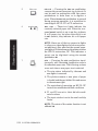
5.
PEN UfO
CJ
PEN UID
-
Pressing the
PEN UIO
pushbutton
It
can be used in conjunction with the cursor
reverses the current pen state (up or down).
pushbuttons to draw lines or to digitize a
point. When the PEN
UfO
pushbutton is pressed
during program execution, it is equivalent to
executing an HP-GL PU or PD instruction.
6.
B/A3 A/A4
• •
These two lights indicate the
currently selected paper size. When the rear
BtA3, AlA'
panel
-
US/MET
switch is set to us, they indicate
A or B paper size, but when the switch is set
to MET (metric), they indicate A4 or A3 paper
size.
NOTE: Since one of the two paper·size lights
is always on, these lights also serve as power
on indicators. Also note that the current paper
size light will blink whenever the plotter receives
the HP·GL instruction, DP. This indicates a
point can he digitized using the ENTER
push button . •
7.
SIZE
Cl
Pressing the SIZE pushbutton simul
taneously with the ENTER pushbutton selects
SIZE
-
the alternate paper size. The following actions
occur each time a new paper size is selected:
a. The size status indicated by the BtA3 and
AiA4 lights is reversed.
b. The plotter assumes a new piece of paper
is loaded and the pen holder lifts and moves
to the extreme right.
c. The equivalent of executing an Hp·GL DF
instruction establishes default conditions.
d. PI and P2 are set to their default coordi·
nate locations.
e. The input window is set to the new hard-clip
limits.
NOTE: The state of the rotate function is not
affected. •
2·18
PLQITER OPERATION
8.
VIEW
D
VIEW
-
on the
Pressing this latching pushbutton turns
ERROR
light, suspends plotting, raises
the pen, and moves the paper so it is fully
extended. In this state you can manually sub
stitute pens and view the entire plotting area.
Pressing the
VIEW
pushbutton again turns off
the ERROR light, returns the pen to its previous
coordinates and status (up or down), and plot
ting resumes.
9.
FAST
- These five cursor pushbuttons are
used to move the pen within the hard-clip
'"
FAST
limits as follows:
Q �,-",
a. Pressing a cursor push button moves the
pen in the direction of the arrow.
h. Pressing adjacent cursor pushbuttons moves
the pen at a 45-degree diagonal between
the two arrow directions.
c. When
FAST
is pressed in conjunction with
any cursor push button, cursor speed is four
times greater.
d. Pressing
FAST
by itself pauses plotting as
long as the pushbutton is held down.
NOTE: Pressing any cursor push button during
plotting will pause the plot and perform the
appropriate cursor motion. Plotting will resume
at the new location when the cursor pushbutton
is released. •
10.
ENTER
Cl
ENTER
-
This multi-purpose pushbutton is
used for changing paper size and the locations
of scaling points PI or P2, rotating the coor
dinate system, storing the currently held pen,
resetting the plotter to power-up default con
ditions, and digitizing.
The enter function is non-latching. This means
the ENTER push button must be pressed simul
taneously with one of the following push
buttons to initiate the defined action.
ENTER + SIZE
Selects the alternate paper
size and initiates the actions defined for the
-
SIZE
push button.
PLO'ITER OPERATION
2-19
ENTER + Pl/P2
Defines the current pen loca
-
tion as the new P I or P2 scaling point. Re
member to set PI first, since P2 moves when
PI is moved. Refer to the section in this chapter
entitled Setting the Scaling Points.
\
ENTER + FAST - Rotates the coordinate system
90·degrees from its current state. Refer to the
section in this chapter entitled Rotating the
Coordinate System.
ENTER + PEN#
-
Stores the pen currently held
in the pen holder into the corresponding num
bered carousel location, if possible. The pen
holder then returns to its previous location.
ENTER + VIEW
-
Resets all power-up default
conditions. This is the same as turning the
power off and then on again.
NOTE: If the pen holder is moved manually,
or an obstruction is encountered, the serv�
motors become inoperative and the ERROR light
starts blinking. In this case, the plotter will
not respond to ENTER + VIEW or any other
front-panel control. The only way to correct
this situation is to remove the obstruction
and cycle the
agai n. •
......,
LINE switch to OFF, then ON
ENTER (digitizing) - The current paper-size
light (e/A3 or AlA4) will blink when the plotter
receives the HP·CL instruction, DP. This blink
ing light indicates the digitizing mode is ini·
tiated and the pen should be moved to the
point to be digitized. If ENTER is then pressed,
the paper-size light stops blinking and the
actual X- and V-coordinates of the point and
the pen status (up or down) are stored in the
plotter's output buffer. This data is output to
the computer when the plotter receives the
HP-CL instruction, OD. Refer to the [nterfae
ing and Programming Manual for complete
digitizing instructions.
Rear Panel
1 1.
2-20
PLOTTER OPERATION
This rocker switch controls application of ac
power to the plotter (refer to Line Voltage
Selection).
12.
This is the power-input socket (refer to Power
Cords).
13.
This is the line power fuse (refer to Fuse
Protection).
Option 001 (RS-232-C/CCITI V.24)
14. �.."'=
'""
�
...'"
This RS·232-C/CCITI V.24 compatible, 25 pin,
female type connector is used to connect the
..,i·.-'::::::":::::1l�1
plotter to a host computer.
This rocker switch controls whether
parity generation and checking will occur for
PARITY 81
PARITY
,·
r, r .
, - B�V)
-
data transmission. If set to "0," no parity
generation or checking will occur. If set to
" 1," parity generation and checking will be
odd or even depending upon the setting of the
52 switch.
PARITY 82
-
This rocker switch establishes the
type of parity to be used, either odd or even,
when the 81 switch is set to " 1. " Setting 82 to
.1 1" establishes odd parity; "0" establishes
even parity.
16.
DIY
-
This rocker switch is used to establish
either programmed "on" or programmed "off'
operation status when the plotter is turned on.
Position D is used when the plotter is directly
connected to a computer (endline operating
environment). In this position, the plotter powers
up in the programmed "on" operating state.
The plotter will respond to all HP·GL and
escape sequence instructions, except the ESC . }
or ESC . Z plotter "off' instructions.
Position Y is used when the plotter is connected
between a terminal and computer (eavesdrop
operating environment). The plotter powers-up
i n the programmed "off' operating state. In
this state, the plotter will pass information
between the terminal and computer; but only
responds to a plotter "on," ESC. ( or ESC . Y
instruction. After receipt of a plotter "on"
instruction, the plotter will respond to all HP
GL and escape sequence instructions.
PLOTTER OPERATION
2·21
NOTE: The plotter's ...... lINE switch must be ON
in order to have any communication between
the terminal and the computer. •
US/MET - This rocker switch is used in com
bination with the A4/A3 rocker switch to select
17.
one of four possible default paper sizes with
the appropriate sized hard-clip limits and de
fault PI /P2 coordinate values. The positions
of the US/MET and A4/A3 switches are checked
only when power is first turned on, or when a
front-panel reset is invoked using the ENTER +
VIEW pushbuttons. Refer to the A4/A3 switch for
,
combination switch settings.
A4/A3 - This rocker switch is used in com
bination with the US/MET rocker switch to
18.
select the default paper size. Combination
switch settings of the US/MET and A4/A3
switches are as follows:
Combination
Switch Settings
Selected Default
Paper Size
US/A4
ANSI A
US/A3
ANSI B
MET/A4
ISO M
MET/A3
ISO A3
After power is turned on, paper size can be
toggled between A and B or A4 and A3 sizes
using the front-panel ENTER + SIZE push buttons.
:!!��:"'''
19 .
I
I,. 8 I. if
'.4flff�
"�r::;:::7
.
BAUD
.
0
BAUD - These four rocker switches are used
to select a baud rate which corresponds with
your computer's data transmission rate. The
baud rate is selected by setting switches 81
through 84 to the appropriate binary bit positions defined in the following table. When set
to "extern al," the baud rate is generated by
an external clock connection at pin 17 of the
RS-232-C/CCITI V.24 connector. For specifi
cations of the external clock, refer to Chapter
1 0 i n the Int erfacing and Programming
Manual.
2-22 PLOTTER OPERATION
One Stop Bit
Baud
Rate
B4 B3 B2
Two Stop Bits
B4 B3 B2 Bl
0
0
75
0
llO
0
0
0
0
0
0
1
1
0
0
1
1
1
0
0
0
1
1
1
0
1
150
200
0
0
0
1
1
1
0
300
600
1200
0
0
1
1
0
0
1
0
1
1
0
1
0
1
1
1
1
1
0
1
2400
4800
0
1
1
1
0
0
0
1
1
1
1
0
9600
1
Option 002 (HP-I B)
This 24-pin Hp·IB connector is used to connect
the plotter to a host computer or other Hp·IB
20.
device.
21.
US/MET
•
..1 ,
,
.
".
.
� <t
..... oq
-,
;;, "' ,
and
A4/A3
-
These two rocker switches
are common to the Hp·IB and RS·232·C inter
face options. Refer to the Option 001 (RS-232-CI
CCITT V.24) controls for their functional
description .
•
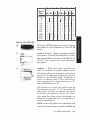
22.
These five rocker switches are
used to establish the plotter address value.
ADDRESS
.J 0
...."'l'""
::' �1'AOORE'Ss
_
.
-
The plotter address is selected by setting each
switch to the appropriate binary bit position
defined in the following table. The plotter is
set to an address code of 05 at the factory .
This corresponds to a listen character of "%"
and a talk character of "E ."
The plotter is i n listen·only mode when all
five switches are set to {Il.l> In this mode, the
plotter does not have an address, but listens
to all data transmitted on the bus. In listen·
only mode the plotter cannot be placed in a
talker-active state and will not respond to a
serial or parallel poll.
NOTE: Listen-only mode is not compatible with
most software packages and plotter ROMs . •
PLO'ITER OP�;RATION
2-23
Address Switch Positions
Address
Characters
Listen
Talk
16
B
0
0
0
0
0
@
A
SP
"
�
$
Address Switch
C
. ' ''''1II�''' ,
:;-i.
'\. " (
D
.
�.
y
��, ,
&
F
o
H
o
G
I
•
J
+
K
L
M
/
o
Settings
N
o
P
1
2
3
4
Q
I 5
L
U
R
S
T
o
8
4
2
1
0
0
0
0
0
0
0
0
0
1
0
0
1
1
0
0
1
0
1
0
-
o
1
1
1
1
1
0
0
0
0
1
1
1
1
1
0
0
1
1
0
0
1
0
1
0
1
0
1
0
1
0
22
23
24
25
26
27
28
29
30
1
1
1
]
31
0
0
1
1
1
1
1
1
1
1
1
1
1
6
7
8
9
10
11
12
13
14
15
16
0
1
1
1
1
1
1
1
1
1
o
o
1
1
o
1
1
1
1
1
1
1
1
I
1
o
o
o
o
o
o
o
o
1
1
o
o
1
1
o
o
1
1
17
18
19
20
r--- ---- -- - - - - - - - - - - - --
V
W
_ __ _ _ _ _
6
7
8
9
X
Y
Z
[
<
\
>
/\
=
J
1
_
_
0
1
2
3
4
0
1
2
3
4
0
1
0
1
0
1
0
1
0
1
0
1
0
1
0
o
0
o
Octal
preset
o
o
De ci mal
'
0
0
0
0
1
1
1
1
0
0
0
0
1
o
Address Codes
_ _ _ _
_ _ _ _
_
_
21
_
_ __
-
6
7
10
11
12
13
14
15
16
17
20
21
22
23
24
-
---,
25
_ _ _
26
27
30
31
32
33
34
...1
Reserved for
HP Desktop
Computer
Address
35
36
r - - - - - - - - - - - - - - - - - - - - - - - - - -,
L?
37
j
Sets Listen
only Mode
Setting Up the Plotter
Setting up your plotter is a simple procedure which consists of loading
pens into the carousel, loading the carousel and plotting medium into
the plotter, and turning on the plotter. The following paragraphs
2-24
PLOTTER OPERATION
describe these procedures and include instructions for choosing the
correct pen and medium combinations.
Choosing the Correct Pen and Medium
To obtain plots of the highest quality, it is important to use pens and
media that are matched to your application. Two types of liber-tip pens
are recommended: one for plotter paper and one for transparency film.
The top of each pen is marked, in a color that matches the pen's ink,
with a three-character code. The first character denotes the media on
which the pen is designed to draw. The "P" is for plotter paper; "T" is
for transparency film. The second and third characters specify, in
millimetres, the approximate line width that the pen will draw.
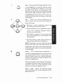
Loading Pens and the Carousel
The following procedure describes how to load pens into the carousel
and how to load the carousel into the plotter.
1.
Select the pen type and pen colors to be loaded into each position of
the carousel. One or more of the pen positions may be used.
2.
Uncap and load each pen into the carousel as follows. Refer to the
following photographs.
3.
a.
Hold the carousel and depress the pen-capping mechanism.
b.
Position the pen collar just below the rounded notch and slide
the pen straight into the pen-holding jaws.
c.
Release the pen-capping mechanism.
Place the carousel on the spindle in the plotter. Rotate the carousel
until it drops into position on the spindle. No force is required.
NOTE: To remove the carousel, lift it straight up. To prevent damage
to the pen tip, always depress the pen-capping mechanism before
removing a pen from the carousel. •
PLOITER OPERATION 2·25
NOTCH
PEN
PEN·HOLDING
JAWS
-
'"
-
'"
SPINDLE
Loading the Pens and the Carousel
Loading the Plotting Medium
The plotter is designed to be used with HP paper and pens. Use of other
paper may cause poor line quality. For best results, order papers listed
under Accessories Available. To load paper, proceed as follows:
1.
Set the US/MET and A4/A3 switches o n the rear panel to the approp
riate positions shown below that correspond with the paper size
being used.
Combination
Switch Settings
Selected Default
Paper Size
US/M
ANSI A
US/A3
ANSI B
MET/A4
ISO A4
MET/A3
ISO A3
NOTE: The positions of the US/MET and M/A3 switches are checked
by the plotter only when power is first turned on, or when a front
panel reset is invoked using the ENTER + VIEW push buttons. After
power is turned on, paper size can be toggled between A and B or
A4 and A3 sizes using the front-panel ENTER + SIZE pushbuttons. •
2.
Check that the right pinch wheel is properly positioned for the
paper being used. Refer to the following illustrations.
2-26 PLOITER OPERATION
NOTE: If necessary, snap the spacer off the shaft, slide the pinch
wheel to the proper position, and snap the spacer back onto the
shaft. •
Pinch Wheel Position for A and B Size Paper
Pinch Wheel Position for A4 and A3 Size Paper
3.
Move the paper loading lever to the PAPER LOAD I position. This
raises the pinch wheels. It also stores and caps the pen to avoid
getting ink on the new paper.
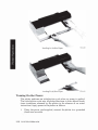
4.
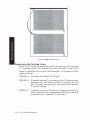
Lay a sheet of paper on the platen surface so the paper is aligned
with the paper guide (the white line at the left rear of the platen)
and the left edge of the platen. A and A4 size paper are loaded with
the long side horizontel. B and A3 size paper are loaded with the
long side vertical. Refer to the following illustration.
5.
Move the paper loading lever to the PAPER HOLD I position. This
lowers the pinch wheels to secure the paper and allow it free movement.
PLO'ITER OPERATION
2-27
Loading AI A4 Size Paper
Loading BI A3 Size Paper
Turning On the Power
The plotter performs an initialization cycle when ac power is applied.
The initialization cycle sets all plotter functions to their default condi
tions (conditions assumed by the plotter in the absence of an actual
instruction). Apply power to the plotter as follows:
1.
2·28
Using the power cord supplied, connect the plotter to a grounded
(three-wire) ac outlet.
PLOTTER OPERATION
CAUTION
To prevent possible damage, ensure the plotter is prop
erly configured for the line voltage in your area. Refer to
Input Power Requirements, Chapter 1 .
2.
Set the -LINE switch to
will occur:
a.
The
ERROR
ON.
The following power·up initialization
light turns on momentarily.
NOTE: if the paper loading lever is in the PAPER
LOAD I
position,
the ERROR light turns on momentarily, then turns on steadily
when the power-up initialization cycle is completed, •
b.
The plotter assumes a new piece of paper has been loaded,
checks the settings of the paper size switches, and performs the
necessary pen holder movements to initialize the X- and y.
coordinate axes. The pen holder is then positioned at the right
hard·clip limit.
c.
In addition to establishing the appropriate hard·clip limits and
PI/P2 frame, the power-up initialization sets the functions
listed in the following table to the indicated conditions. Refer to
the Interfacing and Programming Manual for the explanation
of each function.
After power-up initialization is completed, the first pen select command
will cause the carousel to be initialized. The pen select command can be
invoked programmatically with an Hp·GL command or manually with
the PEN pushbuttons. Carousel initialization consists of backing the
carousel around to its stop before it is advanced to the position that
corresponds with the pen select command.
NOTE: The tapping noise is normal. It is generated by the carousel·
advance mechanism . •
Paper initialization is performed after the carousel is initialized or
when the plotter receives its first move command, depending upon
which occurs first. The command to move can be invoked programmat·
ically with an Hp·GL command or manually with the Pl, P2, or PEN
pushbuttons. The cursor pushbuttons will not cause the paper to be
initialized. Paper initialization consists of fully retracting the paper
and returning it to the starting position prior to completing the com
manded move. This initialization allows the grit wheels to put their
registration marks on the paper before plotting begins.
PLQ'ITER OPERATION
2·29
Power· Up Default Conditions
Function
Equivalent
Instructions
Condition
Plotting mode
PA;
Absolute (plotter units)
Rotation
RO',
o degree (default orientation)
Line type
LT;
Solid line
Line pattern length
L1'n,4;
4% of the diagonal distance between
PI and P2
Pcn state
PU;
Up
Pen velocity
VS,
38.1 cm/s (15 in.!s)
Scaling
SC',
Off (XY coordinates in plotter un its)
Input window
IW;
Set to hard·c1ip limits
Chord angle
,
5 degrees
-
Symbol mode
SM;
Off
Digitize clear
DC,
Digitize mode off
Tick length
TL;
tp
,
=
tn
0.5% of (P2x - PJx) for y.
=
tick and 0.5% of (P2y - Ply) for X·tick
Mask value
IM223,0, 0;
All errors recognized, no service
request, and no parallel poll response
Fill type
FT;
Type I (solid bidirectional shading)
Fill spacing
FT;
1% of the diagonal distance
betwc'Cn PI and P2 (used only for
fill type 3 or 4)
Fill angle
FT',
O·degree
Pen thickness
PT;
0.3 mm (fill spacing for solid fill
types I and 2)
Label origin
Relative character
Current pen location
-
DRI , O;
Horizontal (along X-axis)
direction
Relative character
SR
,
size
Character slant
Label terminator
Character set
Width
SLO;
DTIDJ
SS·,
set
2·30
PLOTIER OPERATlON
1.5% of (P2y - Ply)
ETX (ASCII decimal equivalent 3)
Standard
CSO',
Set 0
CAO',
Set 0
set
Alternate character
0.75% of (P2x - PI x)
=
o degree
selected
Standard character
=
Height
The Demonstration Plot/Confidence Test
The plotter has a built-in demonstration plot that will run on any size
paper. However, the plot is centered only on A-size paper and approxi·
mately centered on A4-size paper. Therefore, if the plotter is set for B- or
A3-size paper, the plotter will automatically switch to the corresponding
smaller paper size before ru�ning the plot. After the demonstration plot
is completed, all plotter functions, except paper size, are returned to
their default conditions and the plotter is ready for normal operation.
Although satisfactory execution of the demonstration plot does not
exclude all possible failures, it does serve as a confidence test since the
probability is very high that the plotter is operating properly. The
demonstration plot is performed as follows:
1.
Load A- or A4-size paper and a full carousel into the plotter. The
carousel may be filled with any combination of pens. However, the
pen widths and colors shown in the following table are recom
mended for drawing the demonstration plot.
2_
Pen Number
Pen Type and Color
1
P.7, black
2
P.3, black
3
P.3, red
4
P.3, green
5
P.3, blue
6
P.3, violet
Initiate the demonstration plot shown on the next page by holding
down the PI and P2 pushbuttons at the same time the plotter is
turned on. Continue depressing P1 and P2 until the tapping noise
begins.
PLO'ITER OPERATION
2-31
Floltt·.. ()pt'ratiol1
6;
.,
GRAPH I C S
::;;
b
�
-l
I MP R O V E S COMMUN I CA T I O N
SALES
t'"1
'"
REVENUE D I STR I B U T I O N
2500 tr-------,
0
."
'"
'"
>
:l
0
Z
-l
;,-
•
<:;)
2000 .-
DIV.
-
12"
3
•
0
�
00
"
•
-
o·
1500 ,-
MANF
- 38"
�
3!
0
-
1000
D I V IDEND H I ST O R Y
/
500
o
�/�
YEARS
NOTES
Chapter
3
Plotter Interconnection
Introduction
This interconnection guide is designed to help you connect the HP 7475A
Graphics Plotter to your computer and verify communication between
them.
IWad the general instructions in the following paragraphs, then locate
and use the interfacing instructions for the computer you are using.
Each instruction set lists a required minimum system configuration,
gives connection instructions for the hardware, and provides a short
program to verify that programming information is being sent cor·
rectly from the computer to the plotter. Once this has been verified, you
can use the Interfacing and Programming Manual to write your own
programs (refer to Accessories Available in Chapter I), or you can use a
software package already written for your computer/plotter system.
If Your Computer Isn't Listed . . .
If your computer isn't listed, there is a good possibility that it still can
be interfaced to the HP 7475A. First, determine which kinds of commu
nication interfaces are available for your computer. If your computer
supports an RS·232-C/CCITI Y.24 interface or an ANSVIEEE 4881978 (HP-IB) interface, then it probably can be interfaced to an
HP 7475A. IWad the manual that describes the communications eqnip
ment for your computer, and then detennine how information is sent
and received. Next, refer to either Chapter 9 or 10 in the HP 7475A
Interfacing and Programming Manual (depending on which interface
you're using) to get a better understanding of how information is sent
and received by the plotter. In the RS-232·C environment, pay particular
attention to the cabling requirements between the computer and the
plotter. (Appendix A contains RS·232·C pin allocations and cable
schematics for Hewlett-Packard cables.) Then, choose a computer con·
figuration in this guide that appears similar to yours and use this as a
guideline for creating your own communication verification program.
PWITER INTERCONNEcrION
3·1
If Your System Configuration Is Different
From the One Listed . . .
There are many variables in computer systems. Often substituting one
piece of hardware or software for another can cause communication
problems. Therefore, if you're going to make substitutions, be aware
that these may affect the operation of the system or the communication
verification program.
If you are having problems getting your system to work with substitute
hardware, carefully read the manual on the substitute equipment. Try
to identify the difference between the hardware you are using and that
which is recommended. Also consult either Chapter 9 or 10 of the Inter
facing and Programming Manual to understand what is required to
communicate with the plotter. Again, in the RS·232-C environment, pay
particular attention to the cabling requirements between the computer
and the plotter. Finally, adapt the interconnection and programming
information for use with your hardware configuration.
If you are having problems getting the program to work with substitute
software, read the software manual, paying particular attention to the
sections dealing with programming the communications hardware.
There are usually two parts to this type of program - opening the com
munications port and writing to the communications port. Opening the
communications port may require specifying a number of interface
parameters, such as baud rate, parity, etc. For more information on
what the plotter requires for communication, see Chapter 9 or 10 of the
Interfacing and Programming Manual. Writing to the communications
port is usually straightforward. The plotter communicates using ASCII
code. Find the output statement in your language that can send an
ASCII string to the communications port. Then adapt the communica
tion verification program for use with your operating system andlor
programming language.
If the Interconnection Doesn't Work .
•
•
If you have connected the system as shown, running the verification
program should cause the plotter to label "COMMUNICATION OK".
If it doesn't, there are a number of things to check:
Is your computer working properly?
•
Check the computer by running a program that you know works.
3-2 PLO'ITER INTERCONNECTION
Is your communications hardware and cable working properly?
•
•
•
•
•
•
Check the interface and cable with another peripheral.
Check that none of the connectors on the computer interface, cable,
or plotter interface are damaged.
Try another cable if one is available.
See that the switches are set properly on your communications
hardware.
Make sure the card is in the proper slot in the computer.
Make sure the output port connected to the plotter is the one specified
by the software.
Is your plotter working properly?
•
Chapter 2 of this manual describes how to perform the HP 7475A
plotter confidence test.
•
Make sure the switches on the back of the plotter are set properly.
•
Check to see that the plotter is turned on, paper is properly loaded,
and the VIEW pushbutton has not been pressed.
Are you using the proper operating system and programming
language?
•
Check to see if you are using the operating system andlor programming language listed in each instruction set.
If you are still having problems, contact your salesperson. Your sales
person will probably be able to help solve your problem or refer you to
someone who can.
If You Are Using a Graphics Software
Package . . .
Some software packages designed to be used with your computer and
the HP 7475A may require you to configure your system differently
than described in this guide. For example, a software package may
require you to use slightly different plotter switch settings. If you are
using a graphics software package with your system, always check the
software documentation to make sure the configuration requirements
are being met.
PW'ITER INTERCONNECI'lON
3-3
Personal Computers
(Compatibles using RS-232-C Interface)
These instructions tell you how to c6nnect your plotter to the following
compatible computers.
AT&T PC 6300
COMPAQ DESKPRO 286 and 386/20
HP Vectra, ES/l2, QS/l6, and RS/20
IBM AT, PC, PC/XT, and PS/2
Computer
AT&T PC 6300,
COMPAQ 286 and 386,
IBM AT, PC, PC/XT, PS/2
with standard serial interface
using a 25-pin male connector
with asynchronous communication
adapter using a 9-pin male connector
HP Vectra, ES/l2, QS/16, RS/20
with HP 24540A or HP 24541A card
using 9-pin male connector
with the HP 2454lA dual serial card
using 25-pin female connector
Cable
HP l7255D
HP 24542G
HP 24542G
HP l 7255M
or HP 13242G
Interconnection Instructions
1.
Turn off your plotter and computer equipment.
2.
If necessary, install the serial interface card. (Refer to your com
puter documentation for details.) If you installed a serial card, go to
step 3.
NOTE: If you have more than one serial port installed, you will need
to know whether you're connecting the plotter to COMl or COM2
(most software will not run on COM3). You will need this information
for testing communications and for configuring your software. If you
are using COM2, be sure to substitute COM2 for COMl in the
instructions. •
34 PLO'ITER INTERCONNECTION
3.
Set the switches on the rear panel of your plotter as shown in the
following illustration. Your plotter checks the switch settings only
when you turn it on, so be sure the plotter is turned off before
changing the switch settings.
Ir=
I
seT TO US POSITION FOR A AND 8
PAPER OR TO MET FOR A4 AND A3 PAPER.
SET TO A4 FOR A AND A4 PAPER
OR TO A3 FOR 8 AND A3 PAPER.
� ti; )- � :Z m ; !il ii
"-.,.-I
L:=
BAUD
0
PARITY
---.-
tu � L
...
� SET 84 AND 82 TO . , . AND 83 AND
B1 TO · 0 " FOR 9600 BAUD RATE.
seT Sl TO · 0 · FOR
NO PARITY. SETTING
OF 82 1 8 IRRELEVANT.
4.
-I
SET TO POSITION · D" FOR ENDUNE
OPERATING ENVIRONMENT.
Connect the plotter to the computer. The following illustration
shows an HP Vectra PC. Be sure you are using the correct cable for
your computer and plotter .
Q
Q
Monitor
power
cord
Computer
power
cord
Plotter
power
cord
RS-232-C
Video
cable
cable
PLO'ITER INTERCONNECTION
3-5
Testing Communication without BASIC
To test the computer/plotter interface without using BASIC, turn on
your computer and plotter, load pens and paper, then follow these
steps.
1.
At the DOS prompt, type the following (substitute COM2 for
COM1, if necessary) and press ENTER.
MODE COM1: 9600 , N , 8 , 1 , P
This sets the RS·232-C port for 9600 baud, no parity, 8 data bits,
one stop bit, and continuous error checking.
2.
Type the following (substitute COM2 for COM1, if necessary) and
press ENTER.
ECHO I N ; SP1 ;PA0 , 0 ; PD0 , 1S00 , 1S00, 1S00 , 0 , 0 ; SP0>COMl
The plotter selects pen #1, draws a triangle on the page, and
returns the pen to the carousel.
Testing Communication with BASIC
To test the computer/plotter interface, turn on your computer and
plotter, load pens and paper, then follow these steps.
1.
At the DOS prompt, type the following (substitute COM2 for
COM1, if necessary) and press ENTER.
MODE COM1 : 9600 , N , 8 , 1 , P
This sets the RS-232-C port for 9600 baud, no parity, 8 data bits,
one stop bit, and continuous error checking.
2.
,
Enter and run the following BASIC program (substitute COM2 for
COM1, if necessary). (If you need help entering and running the
program, refer to your computer documentation.)
10 OPEN ' ' COM1 : %00 , N , 8 , 1 , RS , CS65535 , D S , C D "
AS �1
20 PRINT 1::t1 . " " IN ; OI ; "
30 INPUT � 1 , ID$
40 PRINT � l , • 'SP1 ; PA500,500 ; "
50 PRINT � l , " L B " + ID$+" PLOTTER OI< " +cHR$ ( 3 )
6 0 PRINT � l , " PA0 , 0 ;SP0 ; "
70 END
Your plotter selects pen #1 and prints
3-6 PLQ'ITER INTERCONNECTION
Apple lIe or 11 Plus Computer
(RS-232-C Interface)
Cable
Computer
Apple lIe or 11 Plus
HP 17355M
Apple Super Serial Card
(Apple Part No. A2BOO44)
Interconnection Instructions
1.
Install the Apple Super Serial Card as follows (refer to your com
puter documentation for details).
a. Set the two banks of switches on the serial card as shown here:
1
2
3
4
5
6
7
SW1
Off
On
Off
On
Off
On
On
SW2
On
Off
Off
On
Off
Off
Off
b. With your computer unplugged, install the serial card in slot #2
of the computer. Make sure that the arrow on the card's jumper
block is pointing toward the word "TERMINAL."
PLO'ITER INTERCONNECTION 3-7
2.
With your plotter and computer turned off, connect the plotter to
the computer using the RS-232-C cable as shown below. Either end
of the cable can be connected to the plotter or the connector on the
installed serial card (port #2). The following illustration shows an
Apple IIe.
Monitor
power
cord
Video
cable
3.
computer
power
cord
Plotter
power
cord
RS-232-C
cable
Set the switches on the rear panel of your plotter as shown in the
following diagram. Your plotter checks the switch settings only
when you turn it on, so be sure the plotter is turned off before
changing switch settings. (You are not limited to a 2400 baud rate,
but the plotter's baud rate and the baud rate on your serial card
must match.)
SET TO US POSITION FOR A AND B
r------ PAPER OR TO MET FOR A4 AND A3
PAPER.
r----- SET TO A4 FOR A AND A4 PAPER
OR TO A3 FOR B AND A3 PAPER.
��
:::;::::;-"
�
"'-..,-"' 0 .... �
PARITY
.
....
r/
BAUD
-,--
T
SET Sl TO "0" FOR
NO PARITY. SETTING 'OF S2 IS IRRELEVANT.
_
_
_
_
_
_
3-8 PLO'ITER INTERCONNECTION
0
.
SET 84 TO , AND 81 , 82, AND 83
TO "0· FOR 2400 BAUD RATE.
�
SET TO POSITION 0 FOR ENDLlNE
OPERATING ENVIRONMENT .
"
"
Running the Test Program
To test the computer/plotter interface, turn on your computer and plot
ter, load pens and paper, and enter and run the following BASIC pro
gram. (If you need help entering and running the program, refer to your
computer documentation.)
1 0 PR.2
,
IN.2
20 PRINT CHRS( Z7 ) t
" , M50 , 5 3 , 1 3 , 1 3 ' ·
30 PRINT
"IN,OI , ·
40 INPUT
ID.
50 PRINT
· SP I , PA500. 500 , "
50 PRINT
" L B " , I D' , · COMMUN ICATION OK " , CHR$( 3 )
70 PRINT
· P A0 . 0 , SP0 , "
B0 PR.0
'
I N.0
90 END
Your plotter will select pen #1 and print 7475A COMMUNICATION
OK.
PWITER INTERCONNECTION
3-9
Apple lIe or 11 Plus Computer
(HP-IB Interface)
Cable
Computer
Apple IIe or II Plus
HP lO833A, B, C, or D
Apple IEEE-488 Card
Interconnection Instructions
1.
Install the Apple IEEE-488 Card into Slot #3 (refer to your com
puter documentation for details).
2.
With your plotter and computer turned off, connect the plotter to
the computer using the HP-IB cable as shown below. The foIlowing
illustration shows an Apple IIe.
MonItor
power
cord
Video
cable
Computer
power
cord
3-10 PLOTI'ER INTERCONNECTION
HP-IS
cable
Plotter
power
cord
3.
Set the HP-IB switches on the rear panel of your plotter as shown
in the following diagram. Your plotter checks the switch settings
only when you turn it on, so be sure the plotter is turned off before
changing switch settings.
SET TO US POSITION FOR A AND B
PAPER OR TO MET POSITION FOR
A4 AND A3 PAPER.
16
8
4
2
ADDRESS
I
"-
_
_
_
_
_
_
_
SET S1 AND 4 TO -,- AND 2. 8. AND 1 6
T O ·Ow FOR PLOTTER ADDRESS 5
(EQUIVALENT TO PLOTTER ADDRESS
CHARACTERS % FOR LISTEN AND E
FOR TALK ) .
SET TO A4 FOR A AND A4 PAPER
OR TO A3 FOR B AND A3 PAPER.
Running the Test Program
To test the computer/plotter interface, turn on your compllter and
plotter, load pens and paper, and enter and run the following BASIC
program. (If you need help entering and running the program, refer to
your computer documentation.)
1 0 PRo 3 : I No 3
2 0 PRI NT " W TY." +CHR$ ( 2 6 ) ;
3 0 PRINT " I N ,' SP l I' P R500 I 5 0 0 ,' ' ' I'
4 0 PRI NT " LBCOMMUNI CRTI ON OK" +CHR$ ( 3 ) ;
5 0 PRI NT " PAO, O ; SPO; " ;
6 0 PRI NT CHR $ ( 1 3 ) ;
70 PRo 0 : I N# 0
80
END
Your plotter will select pen #1 and print 7475A COMMUNICATION
OK.
PLOTrER INTERCONNECTION
3-11
Apple 1/1 Computer (RS-232-C Interface)
Computer
Cable
Apple III Unit
Apple 1/1 Modem Eliminator Cable
(Apple Part No. A3M0019) and
HP 17355M
Interconnection Instructions
1.
With your plotter and computer turned off. connect the plotter to the
computer using the RS-232-C and modem eliminator cables as shown
below. Either end of the RS-232-C cable can be connected to the
plotter.
_ I
- ---
Monitor
power
cord
Apple 111
power cord
Video
cable
Apple III modem
eliminator cable
3-12 PLO'ITER INTERCONNECTION
RS-232-C
cable
Plotter
power
cord
2.
Set the switches on the rear panel of your plotter as shown in the
following diagram. Your plotter checks the switch settings only
when you turn it on, so be sure the plotter is turned off before
changing switch settings.
SET TO US POSITION FOR A AND B
,----- PAPER OR TO MET FOR A4 AND A3
PAPER.
,--
_
_
_
_
L...
_
.- �
SET TO A4 FOR A AND A4 PAPER
OR TO A3 FOR B AND A3 PAPER.
--' 0
_
_
_
_
_
�
PARITY
0 � l: \,,_�+.-�'
�
BAUD
T
SET Sl TO ' 0 ' FOR
NO PARITY. SETTING
---r=
SET B4 TO " ' " AND S1 , 8 2 , AND 83
TO " 0 · FOR 2400 BAUD RATE.
'--
_
_
_
_
_
_
OF 52 IS IRRELEVANT.
3.
SET TO POSITION · D � FOR ENOLlNE
OPERATING ENVIRONMENT.
Configure your computer system as follows. (Refer to your Apple
III Standard Device Drivers Manual if you have difficulty with this
step.) In order to run the test program, you will need to make a
copy of your Apple Business BASIC disc that is not write protected.
a. Insert the System Utilities disc. Select the SYSTEM CONFIG.
PROGRAM, then select READ A DRIVER FILE.
b. Load the System Utilities Data disc. Enter the pathname
.D1/RS232.DRIVER and press the RETURN key. Reinsert the
System Utilities disc, and press the ESCAPE key.
c.
Select EDIT DRIVER PARAMETERS. Then select the number cor
responding to .RS232 and press the RETURN key.
d. Select CONFIG BLOCK DATA, then enter the following values
to set the driver to 2400 baud, 7 data bits, space for parity, and
hardwire handshaking.
Byte
0
Value
OA 2E 00 00 00 00 00 00 00 00 00 80
1
2
3
4
5
6
7
8
9
A
B
Press ESCAPE three times to return to the System Configuration
Menu. Select READ A DRIVER FILE and read the other driver flies by
specifying the pathname .D1/S0S.DRIVER. Press ESCAPE to return to
System Configuration Menu. Then select GENERATE NEW SYSTEM.
PLOTTER INTERCONNECTION
3-13
e.
Load the copy of the Apple Business BASIC disc and enter
.DI/SOS.DRIVER as the new driver filename. This loads the new
system configuration on the BASIC disc. Select DELETE
to delete any old system configuration.
Running the Test Program
To test the computer/plotter interface, turn on your computer and
plotter, load pens and paper, and enter and run the following BASIC
program. (If you need help entering and running the program, refer to
your computer documentation.)
10
20
30
40
50
OPEN " O " , 1 , u PLTII
PRINT . 1 , " I N; 5 P 1 ; PA500, 5 00 ; "
PRI N T ' 1 , " LBCOMMUNI CATI O N O K " +CHR$ ( 3 )
PRINT 1 1 , " PAO, O ; 5PO ; "
END
Your plotter will select pen #1 and print 7475A COMMUNICATION
OK.
3-14 PLOTTER INrERCONNECTION
Apple Macintosh/Macintosh Plus/II/SE
(RS-232-C Interface)
Cable
Computer
HP 92219M
HP 17302A
HP 17302A
HP 17302A
Apple Macintosh Computer
Apple Macinl<lsh Plus
Apple Macintosh 11
Apple Macinl<lsh SE
Interconnection Instructions
1.
Turn off your plotter and computer equipment.
2.
Set the switches on the rear panel of your plotter as shown in the
following illustration. Your plotter checks the switch settings only
when you turn it on, so be sure the plotter is turned off before
changing the switch settings.
SET TO US POSITION FOR A AND B
r
- PAPER OR TO MET FOR A4 AND A3
I
PAPER.
,I
_
_
_
_
SET TO A4 FOR A AND A4 PAPER
OR TO A3 FOR B AND A3 PAPER.
SET 84 TO M 1 · AND 8 1 , 82. AND 83
TO MO· FOR 2400 BAUD RATE.
SET S1 TO '0' FOR
NO PARITY. SETTING L.....
OF 52 IS IRRELEVANT.
_
_
_
_
_
_
SET TO POSITION " 0 " FOR ENOLlNE
OPERATING ENVIRONMENT.
PWITER INTERCONNECTION
3·15
3.
Connect the plotter to the computer. The following illustration
shows an Apple Macintosh Computer. Be sure you use the correct
cable for your computer.
o
CI&iliLl
B
Apple III
power cord
_=_r
RS-232-C
cable
Plotter
power
cord
Testing Communication with BASIC
To test the computer/plotter interface, turn on your computer and
plotter, load pens and paper, then enter and run the following BASIC
(Macintosh BASIC 2.0 or higher) program. (If you need help entering
and running the program, refer to your computer documentation.)
10 OPEN "COMl: 9600, N , 8 , l , RS , CS65535 ,DS,CO" AS U
20 PRINT tU , " I N ; O I ; H
30 INPUT nI , 10$
40 PRINT n I , "SPl; PA500 , 500 ; "
50 PRINT nI , " LS " +IO$+" PLOTTER OK" +CHR$ ( 3 )
60 PRINT n I , " P A 0 , 0 ; S P 0 "
70 END
Your plotter selects pen #1 and prints 7475A PLOTTER OK.
NOTE: If you are not using BASIC, a plotter driver is required to run a
Macintosh computer with the plotter. Check with your computer or
plotter dealer for available drivers. (Some packages may require the
baud rate or configuration to be altered. Consult the software package
manual before proceeding.) •
3-16 PLO'ITER INTERCONNECTION
Commodore Amiga Personal Computers
(Serial Interface)
Computer
Cable
17255D
HP 17255M (or 13242G)
HP 17255D
Amiga 500
Amiga
HP
1000
Amiga 2000
Interconnection Instructions
1. With your equipment turned off, use the cable to connect the plotter
to the computer's serial port. (The following illustration shows
Amiga 2000.)
Computer
power
cord
Monitor
power
cord
VIdeo
cable
AS-232-C
cable
an
Plotter
power
cord
PLCYITER INI'ERCONNECTION
3-17
2.
Set the switches on the rear panel of your plotter as shown in the
following diagram. Your plotter checks the switch settings only
when you turn it on, so be sure the plotter is turned off before
changing the switch settings.
Ir=
�
"
"
I
)- � � iD m ; iI)
SET TO US POSITION FOR A AND B
PAPER OR TO MET FOR A4 AND A3 PAPER.
SET TO A4 FOR A AND A4 PAPER
OR TO A3 FOR 8 AND A3 PAPER.
�':�
�__
:�O����!,,::�
,::_�
PARITY
---,seT 5 1 TO · 0 · FOR
NO PARITY. SETTING
OF 52 IS IRRELEVANT.
o
�
B,"D
� SET 84 AND 82 TO " 1 AND 83 AND
8 1 TO · 0 · FOR 9600 BAUD RATE.
�
seT TO POSITION " 0 " FOR ENDLlNE
OPERATING ENVIRONMENT.
3.
Turn on the plotter and boot up the Amiga using your working
copy of the Workbench operation system.
4.
Run the Printer utility in the Workbench Preferences drawer (refer
to Commodore's Workbench documentation).
5.
From the Printer main menu, select the Serial interface.
6.
Save your settings and return to the Preferences drawer.
7.
Set the Amiga's serial port settings as follows (refer to Comm<>
dore's Workbench documentation).
a. Double click on the Serial icon in the Preferences drawer.
b. Select the following settings.
Baud Rate:
Read Bits:
Stop Bits:
Handshaking:
Buffer Size:
Write Bits:
Parity:
c.
9600
8
1
RTS/Cl'S
512 (may be adjusted as needed)
8
None
Save your settings and return to the Workbench.
3-18 PLO'ITER INTERCONNECJ'JON
Verifying Communication
1.
From Workbench, open the Utilities drawer. Start the Notepad
application by double-clicking on the Notepad icon.
2.
Type the following HP-GL commands (uppercase only) into
Notepad.
I N ; SP1 ; SP2 ; SP0 ;
3.
Select Print as Draft, then Print to send the commands to the plotter.
The plotter should select pen #1 and pen #2 sequentiaJIy.
PWITER INTERCONNECTION
3-19
HP Series 200 Personal Technical
Computer (HP-IB Interface)
Computer
Cable
HP Model 216, 226, or 236 Computer
HP 10833A, B, C, or D
Interconnection Instructions
1.
With your plotter and computer turned off, connect the plotter to
the computer using the HP-IB cable shown. Either end of the cable
can be connected to the plotter or computer. The illustration below
shows an HP Model 216 connected to the plotter.
HP-IB
cable
Monitor
power
cord
Computer
power
cord
3-20 PLOTI'ER INTERCONNECTION
Plotter
power
cord
2.
Set the switches on the rear panel of your plotter as shown in the
following diagram. Your plotter checks the switch settings only
when you turn it on, so be sure the plotter is turned off before
changing switch settings.
SET TO US POSITION FOR A ANO B PAPER OR
TO MET POSITION FOR A4 AND A3 PAPER.
(J)
:l
�
�
<
16
8
4
2
1
� o
� L
'_
-.
_
_
__
'
....
-.
__
__
__
__
__
__
__
fW
�
ADDRESS
'---
_
_
_
L-
_
_
_
_
_
_
SET 51 AND 4 TO " , . AND 2 , 8, AND 16 TO · 0 ·
FOR PLOTTER ADDRESS 5 1 E QUIVALENT TO
PLOTTER ADDRESS CHARACTERS % FOR
LISTEN AND E FOR TALK) .
SET TO A4 FOR A AND A4 PAPER
OR TO A3 FOR B AND A3 PAPER.
Running the Test Program
To test the computer/plotter interface, turn on your computer and
plotter, load pens and paper, and enter and run the following BASIC
program. (If you need help entering and running the program, refer to
your computer documentation.)
1 0 OUTPUT 70S
2 0 ENTER 70S ;
; " IN ; O I ; "
10$
30 OUTPUT 70S ; " SP 1 ; PA500 . 500 ; ..
40 OUTPUT 70S ; " LB " & I O$& " COMMUN I C A T I O N O K " &CHR$( 3 )
50 OUTPUT 70S ; " PA0 . 0 ; SP0 ; "
60 END
Your plotter will select pen #1 and print 7475A COMMUNICATION
OK.
PLOTTER INTERCONNECTION 3-21
HP Touchscreen Personal Computer
(HP 150) (RS-232-C Interface)
Cable
Computer
HP Touchscreen or Touchscreen MAX
Personal Computer (or HP 150
System with Dual Disc Drive)
HP 17255M or
HP 13242G
Interconnection Instructions
1.
With your plotter and computer turned off, connect the plotter to
port 2 of the computer using the RS·232-C cable as shown below.
Either end of the cable can be connected to the plotter or computer.
Computer
power
cord
3-22 PLOTrER INTERCONNECTION
RS-232-C
cable
Plotter
power
cord
2.
Set the switches on the rear panel of your plotter as shown in the
following diagram. Your plotter checks the switch settings only
when you turn it on, so be sure the plotter is turned off before
changing switch settings.
SET TO US POSITION FOR A AND B
,------ PAPER OR TO MET FOR A4 AND A3
PAPER,
,-
_
_
_
_
SET Sl TO - 0 · FOR
NO PARITY, SETTING LOF S2 IS IRRELEVANT,
_
_
_
_
_
_
3.
SET TO A4 FOR A AND A4 PAPER
OR TO A3 FOR B AND A3 PAPER.
SET 84 and 82 TO · 1 " AND 83 AND B1
TO "0" FOR 9600 BAUD RATE,
SET TO POSITION "0" FOR ENOLlNE
OPERATING ENVIRONMENT.
Configure your computer system as follows. (Refer to your com
puter documentation if you have difficulty with this step.)
a. Load the MS-DOS System Disc. Touch DEVICE CONFIG. Then
touch START APPLIC to display the DEVICE CONFIGURATION
screen.
b. Touch the PLT field, then use the NEXT CHOICE key to select PLT:
PORT 2. Next, touch SAVE CONFIG.
c.
Press the USERlSYSTEM key on your keyboard twice to change
the function key selections. Then select CONFIG KEYS.
d. Select the PORT 2 CONFIG field to display the PORT 2 screen.
Press the SYSTEM DEFAULTS key, then the DEFAULT VALUES key.
Use the NEXT CHOICE key to select BAUD RATE 9600. Then use the
cursor controls to select the CS(CB)XMlT field. Use the NEXT
CHOICE key to set the field to YES.
e. Touch SAVE CONFIG to save the new configuration. Hold down
the SHIFT key and press the USER/SYSTEM key. Press the EXIT
CONFIG to return to P.A.M.
PLOTTER INTERCONNECTION
3-23
Running the Test Program
To test the computer/plotter interface, turn on your computer and
plotter, load pens and paper, and enter and run the following BASIC
program. (If you need help entering and running the program, refer to
your computer documentation.)
1 0 OPEN ' O ' , I , " P L T '
2 0 P R I NT # 1 ,
' IN ; O I ; "
30 CLOSE 1 1
4 0 OPEN " I ' , 2 , ' PLT"
50 INPUT 1 2 ,
60 OPEN
ID$
" O " , I , " PLT"
70 PRINT 1 1 ,
" S Pl ; PA50 0 , 50 0 ; "
80 P R I N T 1 1 ,
" L B " ; I D$ ; "
90 P R I N T 1 1 ,
" P A0 , 0 ; SP 0 ; "
COMMUN I CA T I ON O K " +CHR$ ( 3 )
1 00 END
Your plotter will select pen #1 and print 7475A COMMUNICATION
OK.
3-24
PWITER INTERCONNECTION
HP Touchscreen Personal Computer
(HP 150) (HP-IB Interface)
Cable
Computer
HP Touchscreen or Touchscreen MAX
Personal Computer (or HP 150
System with Dual Disc Drive)
HP lO833A, B, C, or D
Interconnection Instructions
1.
With your plotter and computer turned off, connect the plotter to
port 2 of the computer using the HP-IB cable as shown below_
Either end of the cable can be connected to the plotter or computer.
Computer
power
cord
HP-IS
cable
Plotter
power
cord
PLO'ITER INTERCONNECTION
3-25
Set the switches on the rear panel of your plotter as shown in the
following diagram. Your plotter checks the switch settings only
when you turn it on, so be sure the plotter is turned off before
2.
changing switch settings.
SET TO US POSITION FOR A AND B PAPER OR
TO MET POSITION FOR A4 AND A3 PAPER.
(f)
:J
'-t-
�
<
16
8
4
2
--' 0
_
_
_
_
_
_
W
:::;
'S:
-.
L
+
.J
ADDRESS
IL
_
_
_
L-
_
_
_
_
_
_
3.
SET S1 AND 4 TO ' 1 ' AND 2, 6. AND 1 6 TO
FOR PLOTTER ADDRESS 5 1 EOUIVALENT TO
PLOTTER ADDRESS CHARACTERS % FOR
LISTEN AND E FOR TALK} .
"0'
SET TO A4 FOR A AND A4 PAPER
OR TO A3 FOR B AND A3 PAPER.
Configure your computer system as follows. (Refer to your computer
documentation if you have difficulty with this step.)
a. Load the MS-DOS System Disc. Touch DEVICE CONFIG. Then
touch START APPUC to display the device configuration screen.
b. Touch the PLT field, then use the NEXT CHOICE key to select PLT,
HP·IB 5. Touch SAVE CONFlG to save the configuration.
c.
Press EXIT CONFlG key to return to P.A.M.
Running the Test Program
To test the computer/plotter interface, turn on your computer and
plotter, load pens and paper, and enter and run the following BASIC
program. (If you need help entering and running the program, refer to
your computer documentation.)
Your plotter will select pen #1 and print COMMUNICATION OK.
3-26 PLOTTER INTERCONNECTION
Set the plotter switches on the back panel as shown by the following
diagram.
I,
SET TO us POSITION FOR A AND B PAPER
OR TO MET FOR A 4 AN O A 3 PAPER.
SET TO A 4 FOR A AND A 4 PAPER
OR TO A3 FOR B AND A 3 PAPER.
I
o
__
....
•
0
PAI"Ury
::,;;
T
seT s 1 TO "0" FOR
NO PARITY, SETTING
OF 52 IS I RRELEVANT
. '
<
BAUD
T
L-
L
_
_
_
_
_
_
SET B 4 AND B 2 TO " 1 " AND
8 3 AND B 1 TO "0" FOR
9600 BAUD RATE.
SET TO POSITION "0" FOR
E N D U N E OPERATING SYSTEM
Set the DEC 1 00's printer port configuration as follows: Press the "Set
Up" key. then press th "Next Screen" key three times to display the
Printer set-up. Use t e arrow keys to change the screen to read
"8N DATA BIP" and "r6O<FXMIT/RCV BAUD" .
1.
�
Communication Verification
Load pens and paper a d run the following MBASI C program:
1 0 LPRI N T
20
" IN;"
+" , 1 8 0 ; 0 ; 1 7 : "
1
+ " . NO ; 1 9 : 1
LPRINT
CHR $ ( 2 7
30
LPRI NT
CHR$ ( 2 7
40
LPRINT
" SP 1 j P A 00 , 5 00 j "
5 0 L P R I N T .. LBCOMM
60
70
LPRI N T
E,W
" PRO , O j
NI CAT! O N
11
OKII +CHR$ ( 3 )
PO;
Plotter labels: COMMU ICATION OK
PLOTI�R INTERCONNECTION 3-27
Chapter
4
Selecting Pens
and Media
Introduction
This chapter describes the pens and media that can be used with your
plotter, and how to combine them for best results.
For the highest quality plots, use only Hewlett·Packard supplies.
Hewlett·Packard pens and media work together for optimal pen life,
plot quality, and plotter performance. The chemical reaction between
the pens and media is tested to ensure that fading and color changes
are minimized. The smoothness of HP paper reduces abrasion on pen
tips and produces a sharp, crisp ink line.
The Supplies and Cables brochure, shipped with your plotter, gives part
numbers and ordering information for Hewlett·Packard pens and
media.
Pens
Your plotter can use fiber·tip paper pens, transparency pens, and short·
body refillable drafting pens. Fiber·tip paper and transparency pens
are available in vivid, matching colors for duplicating paper and
overhead graphics. The following table describes each pen type.
Pen Type
Characteristics
Fiber·tip paper
Easy to use, economic. Even ink flow
produces high-quality characters and
opaque lines. Disposable.
Fiber·tip transparency
Easy to use, economic. Extra dye pro·
duces strong colors for overhead pro·
jection. Water·based. Disposable.
Short·body drafting
Produces highest-quality lines. Long
lasting tungsten carbide points. Requires refilling and maintenance.
SELECTING PENS AND MEDIA 4·1
Fiber-tip pens will last at least 30 days stored in the carousel. However,
if you do not plan to plot for several days, remove the pens from the
carousel and cap them to ensure a longer pen life.
Remove drafting pens and cap them immediately after use to prevent
drying and clogging. Drafting pens require cleaning after each use.
Remember that ink dries as quickly in the drafting pen as it does on
the plotting media. Here are the maximum times that ink can remain
in a drafting pen in an average environment.
•
20 seconds if the pen is uncapped and not in use.
•
One day if the pen is in a drafting pen carousel.
•
One week if the pen is properly capped and stored in a honwntal
position.
Symptoms and Solutions
Drafting pens provide the highest quality lines available on the plotter.
If you are not getting the quality of output you desire, consult the
following table. It will help you diagnose and correct output problems.
Symptoms and Solutions
Problem
Possible Cause
Solution
Pen is clogged.
Clean the pen.
Cleaning wire is
bent.
Replaoe the point.
Beginning of a
line does not
show.
Ink is starting to
dry in the tip.
Before plotting,
draw lines by
hand, dip tip in
water, or use a
synnge.
Pen skips or
drags.
Pen is partially
blocked.
Clean the pen
and the boot.
There is oil on the
medium.
Replace the
sheet, keep hands
clean, handle
sheets along the
edges.
Tip is worn out.
Replace the tip.
Point is too fine.
Do not use
0.18 mm and
0.25 mm points.
Pen does not
write.
Pen tip clogs
frequently.
4-2 SELECTING PENS AND MEDIA
Symptoms and Solutions (Continued)
Problem
Possible Cause
Solution
There is static
buildup on the
medium.
Reduce pen
speed, increase
humidity, use
static-resistant
film or another
medium.
Ink leaks
between the point
and adaptor.
Internal airflow is
obstructed or vent
is clogged.
Clean the pen.
Pen tips wear out
rapidly.
Film surface is
abrasive.
Use HP film.
Lines look
wavy.
Pen tip is
damaged.
If the tip is not
centered, replace
it.
Plotter may need
adjustment.
If wavy lines are
not caused by a
damaged pen,
contact an HP
servIce
representative.
Line width is not
uniform.
Pen is dirty.
Clean the pen.
Ink flow is
insufficient.
Reduce.pen speed
or use thinner
ink.
Ink flow is
uneven.
Pen is dirty.
Clean the pen.
Pen speed is too
fast.
Reduce pen
speed.
Pen is running
out of ink.
Refill the
reservoir before it
is empty.
Ink is too thick
for the pen point.
Use a wider point
or dilute the ink
with distilled
water.
Ink and medium
are incompatible.
Change the ink
or the medium.
Ink smears or
doesn't dry.
SELECTING PENS AND MEDIA
4-3
Symptoms and Solutions (Continued)
Problem
Possible Cause
Solution
Ink fades or
separates.
The ink is old.
Use a new bottle
of ink.
Boot is deteriorating.
Ink was diluted
with acetone.
Replace the boot.
Dilute ink with
distilled water,
not acetone.
Media
You can use non·glossy plotter paper, glossy plotter paper, transparency
plotter film, and double-matte polyester film with your plotter. The
following table describes each of these plotting media.
Characteristics
Media Type
Non·glossy
plotter paper
Smooth surface, clear line definition. Easy to
handle, good for everyday use. Inexpensive.
Glossy plotter
paper
Gloss finish, heavy weight. Good for reports
and handouts. Regular use requires frequent
grit wheel cleaning to prevent residue bujld
up.
Transparency
plotter film
High·grade, clear. Good for presentations.
Paper backing protects film during plotting.
Double-matte
polyester film'
Finely coated and translucent. Good for high·
accuracy applications and archive storage.
Dimensionally stable. Expensive.
*Film of standard thickness, 3-mil, is recommended for best results.
Handle your plotting media by the edges when preparing final plots.
Oil from fingerprints can prevent ink from adhering to the medium.
Plotting media, particularly paper, can be affected by changes in
temperature and humidity. Plotting distortions will occur if the medium
shrinks or stretches. Stabilize your media by removing a sheet from the
package and exposing it to air near the plotter for at least 15 minutes
before using it. (This is not necessary for media from an open package
that has been exposed to the plotter's environment for several days.)
Media with rounded corners are not recommended for use with your
plotter. Square corners are necessary for the pinch wheels to grip and
move the media accurately.
4-4 SELECTING PENS AND MEDIA
Combining Pens and Media
U se the following ta ble to select the types of pens and m ed ia that work
best tog ether and fi t your appl ication. Th e recommend ed plotti ng speed
(i n centim etres per second ) is l isted for each com bination
.
Fiber-tip
Paper Pens
Non-Glossy
Plotter Paper
Hig h q uality
for business
g raphics
chart s and
q ui ck check
plots.
Fiber-tip
Transparency
Pens
Drafting
Pens
Not
recomm end ed.
N ot
recomm end ed.
Good q uali ty.
N ot
recomm end ed.
38 cm /.
Glossy
Plotter Paper
Ex cellent
q uality for
presentati ons,
reports, and
hand outs.
V ivid, professional
resul ts
.
10 cm /s
10 cm /.
Transparency
Plotter Film
N ot
recommended.
Ex cellent
q uality for
overhead
presentat ions
and overl ays.
N ot
recomm end ed.
10 cm /s
Double-matte
Polyester
Film
Not
recomm ended.
Not
recomm end ed.
Excell ent
q uali ty.
Sharp, uniform lines.
Good contrast
for reprod uctions
.
15 cm /.
SELECTING PENS AND MEDIA
4-5
NOTES
Appendix
A
RS-232-C/CCITT V.24
Interface Information
Introduction
The RS·232·C in terface is a stan dard serial in terface compati ble with
many computers an d tenn in al s. This appen dix provi de s a summary of
RS·232·C in te rface specifi cati on s in cl udin g pin allocation s an d cable
schemati cs
.
RS-232-C Pin Allocations
The pl otte r in te rface s to the RS·232·C commun ication s lin es through a
stan dard 25 ·pin femal e connector
. Conn ector pin allocation s are iden ti·
fi ed an d described in the following tabl e.
Wire/Signal Name
Pin #
RS-232-C
CCITT Y.24
Protecti ve Groun d
1
AA
101
Tran smitted Data
2
BA
103
Received Data
3
BB
104
Reque st to S en d
4
CA
105
Clear to S en d
5
CB
106
Data Set Re ady
6
CC
107
Signal Gro un d
7
AB
102
Data Carrier De te ct
8
CF
109
S econ dary Tran smit Data "
14
S BA
118
S econ dary Re ceive Data"
16
S BB
119
Data Tenninal Ready
20
CD
108.2
'Pins 14 and 16
configurations.
are
wired only in the Y-cable (Part No. HP 17455A) used in eavesdrop
RS-232-C INTERFACING
A·1
RS-232-C Cable Schematics
The following cable schematics are for Hewlett-Packard cables.
Connector Type (25-pin)
HP Part Number
17255D
17255M
or
13242G'
Plotter End
Computer End
male
male
female
male
r-
-
I---
e-
f-2
r3
,
3
1
2
I---
e-
f-20
rS
s
6
7
I---
f-6
'--
7
e-
r20
�
·Symmetrical; either end may be connected to the plotter. Other pins are connected. in the
13242G but do not affect plotter operations.
A-2 RS-232·C INTERFACING
Connector Type
HP Pari Number
17302A
Plotter End
Computer End
male (25-pin)
male (8�pin mini din)
20
2
3
3
2
5
4
7
8
RS-232-C INTERFACING
A-3
Connector Type (25.pin)
HP Part Number
173550
17355M
•
1
2
3
•
•
•
I I
25
•
Plotter End
Computer End
male
male
female
mate
/-,
T
:
:I
I
I
I
I
I
I
I
I
I
\
j
'- - ...
Symmetncal; either end may be connected to the plotter.
A-4 RS-232-C INTERFACING
1
2
3
•
•
•
I I
25
Connector Type (25-pin)
HP Part Number
Plotter End
17455A
male
Computer End
male (computer)
female (terminal)
Computer
-
1 I3 1 2 1 7 1 ' 1 _ 1 5 6 1 1 25
II
I I
I
I
: :
32
f-7
f-;
f-1 6 II II
f-1_ "-)
I--
8
/-,
I
I
'--
Plotter
T
I
I
I
1
--
II
II
-I
'
r3 1 2 1 7 1 ' \ -T 5 6 I I - - 25
8
Terminal
(pins
4, 5, 6,
and 8 through 25 are directly connected between the
computer and lerminal connectors)
ilS-232·C INTER,'ACING A-5
Connector Type
HP Part Number
Plotter End
Computer End
24542G
male (25-pin)
female (9-pin)
-
-
-
r--
-
r3
1
4
2
2
3
-
r--
-
L-
5
4
6
'7
.--
L-
re
5
r20
r6
r7
s
'--
Connector Type
HP Part Number
Plotter End
92219M
male (25-pin)
Computer End
male (9-pin)
1
1
7
3
3
5
20
7
2
9
A-6 RS-232-C INTERFACING
Subject Index
a
AGL (A Graphics Language)
definition of . . . . . . . . . . . . . . . . . . . . . . . . . . . . . . . . . . . . . . . . . . . . . . . . . 2-3
scaling and . . . . . . . . . . . . . . . . . . . . . . . . . . . . . . . . . . . . . . . . . . . . . . . . . . 2·8
Accessories
available . . . . . . . . . . . . . . . . . . . . . . . . . . . . . . . . . . . . . . . . . . . . . . . . . . . . 1-3
inventory . . . . . . . . . . . . . . . . . . . . . . . . . . . . . . . . . . . . . . . . . . . . . . . . . . . 1-2
ordering . . . . . . . . . . . . . . . . . . . . . . . . . . . . . . . . . . . . . . . . . . . . . . . . . . . . . 1-3
supplied
1·3
Apple lIe/lI Plus Computer (HP·IB), plotter and . . . . . . . . . . . . 3-20-3-21
Apple lIe/lI Plus Computer (RS-232·C), plotter and . . . . . . . . . . 3-18-3-19
Apple IIC Computer, plotter and . . . . . . . . . . . . . . . . . . . . . . . . . . . 3-22-3-23
Apple 111 Computer, plotter and . . . . . . . . . . . . . . . . . . . . . . . . . . . . 3·22-3-23
.
.
.
.
.
.
.
.
.
.
.
.
.
.
.
.
.
.
.
.
.
.
.
.
.
.
.
.
.
.
.
.
.
.
.
.
.
.
.
.
.
.
.
.
.
.
.
.
.
.
.
.
.
b
Baud rate
. .
.
. .
. .
. . ...
2-22
. .
SWl·tches , . .
switch settings . . . . . . . . . . . . . . . . . . . . . . . . . . . . . . . . . . . . . . . . . . . . . 2-23
.
.
.
.
.
.
.
.
.
.
.
.
.
.
.
.
.
.
.
.
.
.
.
.
. .
.
.
.
.
.
.
.
.
C
Carousel
initialization and . . . . . . . . . . . . . . . . . . . . . . . . . . . . . . . . . . . . . . . . . . . 2·29
loading the . . . . . . . . . . . . . . . . . . . . . . . . . . . . . . . . . . . . . . . . . . . . . 2-25-2-26
removing the . . . . . . . . . . . . . . . . . . . . . . . . . . . . . . . . . . . . . . . . . . . . . . . 2·25
Cartesian coordinate system . . . . . . . . . . . . . . . . . . . . . . . . . . . . . . . . . . . . 2-4
Cleaning
pen carousel . . . . . . . . . . . . . . . . , . . . . . . . . . . . . . . . . . . . . . . . . . . . . . . . . 1-8
plotter . . . . . . . . . . . . . . . . . . . . . . . . . . . . . . . . . . . . . . . . . . . . . . . . . . . 1·7-1-8
Commodore CBM 8032 Computer (HP-IB), plotter and . . . . . . . 3-24-3·25
Confidence test see Demonstration plot
Configuration, system . . . . . . . . . . . . . . . . . . . . . . . . . . . . . . . . . . . . . . . . . . 3-2
Controls
configuration . . . . . . . . . . . . . . . . . . . . . . . . . . . . . . . . . . . . . . . . . . . . . . . 2·14
front panel see Front panel
interface . . . . . . . . . . . . . . . . . . . . . . . . . . . . . . . . . . . . . . . . . . . . . . . . . . . 2-14
Coordinate system
Cartesian see Cartesian coordinate system
default orientation of . . . . . . . . . . . . . . . . . . . . . . . . . . . . . . . . . . . . . . . . 2-6
origin, location of . . . . . . . . . . . . . . . . . . . . . . . . . . . . . . . . . . . . . . . . . . . . 2-5
orientation of
.. .. .
. . . . . . . . . . . . . . . . . . . . . . . . . . . . . 2-5
paper size and . . . . . . . . . . . . . . . . . . . . . . . . . . . . . . . . . . . . . . . 2-5, 2-6, 2-7
plotter . . . . . . . . . . . . . . . . . . . . . . . . . . . . . . . . . . . . . . . . . . . . . . . . . . 2·4, 2-13
.
.
.
.
.
.
.
.
.
.
.
.
.
.
.
SUBJECT INDEX
SI·1
Subject Index (Continued)
C (Continued)
Coordinate system
Cartesian see Cartesian coordinate system
default orientation of . . . . . . . . . . . . . . . . . . . . . . . . . . . . . . . . . . . . . . . " 2-6
origin, location of
2·5
orientation of ' " . . . . . . . . . . . . . . . . . . . . . . . . . . . . . . . . . . . . . . . . . . . . . 2·5
paper size and . . . . . . . . . . . . . . . . . . . . . . . . . . . . . . . . . . . . . . . 2-5, 2-6, 2·7
plotter . . . . . . . . . . . . . . . . . . . . . . . . . . . . . . . . . . . . . . . . . . . . . . . . . . 2·4, 2·13
paper size and . . . . . . . . . . . . . . . . , . . . . . . . . . . . . . . . . . . . . . . . 2-5, 2-6, 2·7
rotating the . . . . . . . . . . . . . . . . . . . . . . . . . . . . . . . . . . . . . . . . . . . . 2·12-2·14
.
.
.
.
.
.
.
.
.
.
.
.
.
.
.
.
.
.
.
.
.
.
.
.
.
.
.
.
.
•
.
.
.
.
.
.
.
.
.
.
.
.
.
.
d
D/Y (programmed on/off) switch . . . . . . . . . . . . . . . . . . . . . . . . . . . . . . 2·21
Default
input window . . . . . . . . . . . . . . . . . . . . . . . . . . . . . . . . . . . . . . . . . . . . . . . . 2·5
orientaton, coordinate system see Coordinate system
P1/P2, location of . . . . . . . . . . . . . . . . . . . . . . . . . . . . . . . . . . . . 2-5, 2·7, 2·16
power-up conditions see Power up
Demonstration plot . . . . . . . . . . . . . . . . . . . . . . . . . . . . . . . . . . . . . . . 2·31-2-32
Digitizing
2·20
Documentation, plotter . . . . . . . . . . . . . . . . . . . . . . . . . . . . . . . . . . . . . . . . . 1·1
.
.
.
.
.
.
.
.
.
.
.
.
.
.
.
.
.
.
.
.
.
.
.
.
.
.
.
.
.
.
.
.
.
.
.
.
.
.
.
.
.
.
.
.
.
.
.
.
.
.
.
.
e
Eavesdrop operating environment . . . . . . . . . . . . . . . . . . . . . . . . . . . . . 2-21
Endline (standalone) operating environment . .
.
. . . 2·21
Enter pushbutton
digitizing and the . . . . . . . . . . . . . . . . . . . . . . . . . . . . . . . . . . . . . . . . . . . 2·20
Fast pushbutton interaction with . . . . . . . . . . . . . . . . . . . . . . . . . . . . 2·22
paper size lights and . . . . . . . . . . . . . . . . . . . . . . . . . . . . . . . . . . . . . . . . 2·18
Paper Size pushbutton interaction with . . . , . . . . . . . . . 2·19, 2-22, 2·26
Pen pushbuttons interaction with . . . . . . . . . . . . . . . . . . . . . . . . . . . . 2-20
Setting P1/P2 and the . . . . . . . . . . . . . . . . . . . . . . . . . . . . . . . . . 2·16, 2·20
using the . . . . . . . . . . . . . . . . . . . . . . . . . . . . . . . . . . . . . . . . . . . . . . . 2·19-2·20
View pushbutton interaction with . . . . . . . . . . . . . . . . . . . . . . . 2·20, 2·26
Error light . . . . . . . . . . . . . . . . . . . . . . . . . . . . . . . . . . . . . . . . . . 2·16, 2·17, 2·29
.
.
.
.
.
.
.
.
.
.
. .
•
.
f
Fast pushbutton, using the . . . . . . . . . . . . . . . . . . . . . . . . . . . . . . . . . . . . 2-19
Film (plotting media)
double-matte polyester . . . . . . . . . . . . . . . . . . . . . . . . . . . . . . . . . . . . 4-4, 4·5
overhead transparency . . . . . . . . . . . . . . . . . . . . . . . . . . . 2·25, 4·1, 4-4, 4-5
SI·2 SUBJECT INDEX
Subject Index (Continued)
f (Continued)
Front panel
indicators . . . . . . . . . . . . . . . . . . . . . . . . . . . . . . . . . . . . . . . . . 2-17, 2-18, 2-29
functions . . . . . . . . . . . . . . . . . . . . . . . . . . . . . . . . . . . . . . . . . . . . . . . 2-14-2-20
Fuse
. .
.
..
1-5, 2-21
.
.
.
.
.
.
.
.
.
.
.
_
.
.
.
.
.
.
.
.
.
.
.
.
.
.
.
.
.
.
.
.
.
.
.
.
.
.
.
.
.
.
.
.
.
.
.
.
.
g
Grid spacing (resolution) . . . . . . . . . . . . . . . . . . . . . . . . . . . . . . . . . . . . . . . 2-4
1-5
.
Grounding, requirements for
.
.
.
.
.
.
.
.
.
.
.
.
.
.
.
.
.
.
.
.
.
.
.
.
.
.
.
.
.
.
.
_
.
.
.
h
HP 150 Computer (HP-IB) . . . . . . . . . . . . . . . . . . . . . . . . . . . . . . . . . 3-25-3-26
HP 150 Computer (RS-232-C) . . . . . . . . . . . . . . . . . . . . . , . . . . . . . . 3-22-3-24
HP 9000 Series 200 Computer . . . . . . . . . . . . . . . . . . . . . . . . . . . . . . 3-20-3-21
HP Touchscreen Computer see HP 150 Computer
HP Vectra, ES/12, QS/16, and RS/20 . . . . . . . . . . . . . . . . . . . . . . . . 3-4-3-6
HP-GL (Hewlett-Packard Graphics Language)
definition of . . . . . . . . . . . . . . . . . . . . . . . . . . . . . . . . . . , . . , . . . . . . . . . . . 2-3
scaling and . . . . . . . . . . . . . . . . . . . . . . . . . . . . . . . . . . . . . . . . . . . . . . . . . . 2-7
HP-IB (Hewlett-Packard Interface Bus) (Option 002)
address switches and positions . . . . . . . . . . . . . . . . . . . . . . 2-23, 2-24, 3-4
listen-oniy mode and . . . . . . . . . . . . . . . . . . . . . . . . . . . . . . . . . . . . . . . . 2-23
US/MET switch and . . . . . . . . . . . . . . . . . . . . . . . . . . . . . . . . . . . . . . . . 2-23
..
Hard-elip limits
.
. .
. . . . 2-5
.
.
.
.
.
.
.
.
.
.
.
.
.
.
.
.
.
.
.
.
.
.
.
.
.
.
.
.
.
.
.
.
.
.
.
.
_
.
.
1
•
IBM Personal Computer, AT, PC, PC/XT, and PS/2
3-4-3-6
Indicators, front panel see Front panel
Initialization see Carousel, Paper, Plotter
Input window . . . . . . . . . . . . . . . . . . . . . . . . . . . . . . . . . , . . , . . . . . . . . 2-5, 2-18
Inspection, initial . . . . . . . . . . . . . . . . . . . . . . . . . . . . . . . , . . . . . . " . . . . . . 1-2
Interconnection
graphics software and . , . . . . . . . . . . . . . . . . . . . . . . . . . . . . . . . . . . . . . 3-3
HP-IB and
3-4
nonworking . . . . . . . . . . . . . . . . . . . . . . . . . . . . . . . . . . . . . . . . . . . . . . 3-2-3-3
plotter
..
..
.
.
.
.
. 3-1-3-3
system configuration and . . . . . . . . . . . . . . . . . . . . . . . . . . . . . . . . . . . . 3-2
unlisted computers and . . . . . . . . . . . . . . . . . . . . . . . . . . . . . . . . . . . . 3-1-3-2
.
.
.
.
.
.
.
.
.
.
.
.
.
.
.
.
.
.
.
.
.
.
.
.
.
.
.
.
.
.
.
.
.
.
.
.
.
.
.
.
.
.
.
.
.
.
.
.
.
.
.
.
.
.
.
.
_
.
.
.
.
.
.
.
.
.
.
.
.
.
.
.
.
•
.
.
.
.
.
.
.
.
.
.
.
.
.
.
.
.
.
.
.
.
.
.
.
.
.
.
.
.
SUBJECT INDEX
.
SI-3
Subject Index (Continued)
1
Lever, Paper HoldlLoad
. . . . . . . . . . . . . 2-16
Limits, Hard·clip see Hard·clip limits
Line power fuse see Fuse
Line voltage . . . . . . . . . . . . . . . . . . . . . . . . . . . . . . . . . . . . . . . . . . . . . . . . . . 2-29
Listen-only mode . . . . . . . . . . . . . . . . . . . . . . . . . . . . . . . . . . . . . . . . . . . . . 2-23
Loading
carousel see Carousel
pens see Pens
.
.
.
.
.
.
.
.
.
.
.
.
.
.
.
.
.
.
.
.
.
.
.
.
•
.
m
Maintenance see Cleaning
Major features, location of . . . . . . . . . . . . . . . . . . . . . . . . . 2·1-2-2, 2-14-2-21
Maximum
numeric range see Numeric range
plotting ranges see Plotting ranges
Media see also Paper
choosing the correct . . . . . . . . . . . . . . . . . . . . . . . . . . . . . . . . . . . . . . 2-25, 4·1
loading
2-26, 2·28
pens and see Pens
selecting . . . . . . . . . . . . . . . . . . . . . . . . . . . . . . . . . . . . . . . . . . . . . . . . . 4-1, 4-5
size switches . . . . . . . . . . . . . . . . . . . . . . . . . . . . . . . . . . . . . . . . . . . . . . . 2-22
switch settings and . . . . . . . . . . . . . . . . . . . . . . . . . . . . . . . . . . . . . . . . . 2-26
.
.
.
.
.
.
.
.
.
.
.
.
.
.
.
.
.
.
.
.
.
.
.
. . . .
.
.
.
•
.
.
.
.
.
.
.
.
.
.
.
.
.
.
.
.
n
Numeric range, maximum . . . . . . . . . . . . . . . . . . . . . . . . . . . . . . . . . . . . . . 2-5
o
Option 001 see RS-232-C
Option 002 see HP-IB
P
P1/P2 positions see also Scaling Points
automatic postioning and . . . . . . . . . . . . . . . . . . . . . . . . . . . . . . . . . . . . 2-9
default positions for . .
.
.
. . . . . . . . . 2-9
Enter pushbutton and . . . . . . . . . . . . . . . . . . . . . . . . . . . . . . . . . . . . 2-9, 2-16
PlIP2 pushbuttons
demonstration plot and . . . . . . . . . . . . . . . . . . . . . . . . . . . . . . . . . . . . . 2-31
Enter pushbutton and . . . . . . . . . . . . . . . . . . . . . . . . . . . . . . . . . . . . 2-9, 2-16
paper intialization and . . . . . . . . . . . . . . . . . . . . . . . . . . . . . . . . . . . . . . 2-29
using the
2-16
.
.
.
8I-4 SUBJECT INDEX
.
.
.
.
.
.
.
.
.
.
.
.
.
.
.
.
.
.
.
.
.
.
.
.
.
.
.
.
.
.
.
.
.
.
. .
.
.
.
.
.
.
.
.
.
.
.
.
.
.
.
.
.
.
.
.
.
.
.
.
•
.
.
.
.
.
.
.
.
.
.
.
.
.
.
.
.
Subject Index (Continued)
P
(Continued)
Paper see also Me<lia
glossy plotter . . . . . . . . . . . . . . . . . . . . . . . . . . . . . . . . . . . . . . . . . . . . . 4-4, 4·5
holding
2·16. 2·27
initialization and . . . . . . . . . . . . . . . . . . . . . . . . . . . . . . . . . . . . . . . . . . . 2-29
loading see Me<lia
lever
2·27
non-glossy plotter . . . . . . . . . . . . . . . . . . . . . . . . . . . . . . . . . . . . . . . . . 4·4, 4-5
size lights, Enter pushbutton and . . . . . . . . . . . . . . . . . . . . . . . . . . . . 2·18
Size pushbutton, using the . . . . . . . . . . . . . . . . . . . . . . . . . . . . . . . . . . . 2·18
size settings . . . . . . . . . . . . . . . . . . . . . . . . . . . . . . . . . . . . . . . . . . . . . . . . . 2-6
Parity switches . . . . . . . . . . . . . . . . . . . . . . . . . . . . . . . . . . . . . . . . . . . . . . . 2-21
Pen
carousel cleaning see Cleaning
holder, Error light and . . . . . . . . . . . . . . . . . . . . . . . . . . . . . . . . . . . . . . 2-20
U/D (up/down) pushbutton . . . . . . . . . . . . . . . . . . . . . . . . . . . . . . . . . 2-18
Pens
choosing the correct . . . . . . . . . . . . . . . . . . . . . . . . . . . . . . . . . . . . . . . . . 2·25
drafting . . . . . . . . . . . . . . . . . . . . . . . . . . . . . . . . . . . . . . . . . . . . . . . . . . 4·1-4·5
fiber·tip paper . . . . . . . . . . . . . . . . . . . . . . . . . . . . . . . . . . . . . . . . . . . . 4·1, 4·5
loading . . . . . . . . . . . . . . . . . . . . . . . . . . . . . . . . . . . . . . . . . . . . . . . 2·25, 2-26
media and . . . . . . . . . . . . . . . . . . . . . . . . . . . . . . . . . . . . . . . . . . . . . . . . . . . 4-5
pushbuttons for . . . . . . . . . . . . . . . . . . . . . . . . . . . . . . . . . . . . . . . . 2·17, 2-29
selecting . . . . . . . . . . . . . . . . . . . . . . . . . . . . . . . . . . . . . . . . . . . . . . . . . 4-1, 4·5
symptoms and solutions for . . . . . . . . . . . . . . . . . . . . . . . . . . . . . . . 4·2-4·3
transparency . . . . . . . . . . . . . . . . . . . . . . . . . . . . . . . . . . . . . . . . 2·25, 4·1, 4-4
types of . . . . . . . . . . . . . . . . . . . . . . . . . . . . . . . . . . . . . . . . . . . . . . . . . 2·25, 4·1
Pinch wheel, positioning the . . . . . . . . . . . . . . . . . . . . . . . . . . . . . . . 2-26-2·27
Plots, preparing equal·sized . . . . . . . . . . . . . . . . . . . . . . . . . . . . . . . . . 2·9-2-10
Plotter
address . . . . . . . . . . . . . . . . . . . . . . . . . . . . . . . . . . . . . . . . . . . . 2-23-2-24, 3-4
controls and indicators . . . . . . . . . . . . . . . . . . . . . . . . . . . . . . . . . . 2·14-2-20
coordinate system see Coordinate system
default conditions . . . . . . . . . . . . . . . . . . . . . . . . . . . . . . . . . . . . . . . . . . . 2-30
documentation . . . . . . . . . . . . . . . . . . . . . . . . . . . . . . . . . . . . . . . . . . . . . . 1-1
initialization . . . . . , . . . . . . . . . . . . . . . . . . . . . . . . . . . . . . . . . . . . . . . . . 2-28
interconnection see Interconnection
major features . . . . . . . . . . . . . . . . . . . . . . . . . . . . . . . . . . . . . . . . . . . . 2·1-2·2
maintenance . . . . . . . . . . . . . . . . . . . . . . . . . . . . . . . . . . . . . . . . . . . . . . . . 1-7
rear panel features and switches
2·20-2·23
service . . . . . . . . . . . . . . . . . . . . . . . . . . . . . . . . . . . . . . . . . . . . . . . . . . . 1·8-1·9
setting up the . . . . . . . . . . . . . . . . . . . . . . . . . . . . . . . . . . . . . . . . . . . 2-24-2·30
.
.
.
.
.
.
.
.
.
.
.
.
.
.
.
.
.
.
.
.
.
.
.
.
.
.
.
•
.
.
.
.
.
.
.
.
.
.
.
.
.
.
.
.
.
.
.
.
.
.
.
.
.
.
.
.
.
.
.
.
.
.
.
.
.
.
.
.
.
.
.
.
.
.
.
.
.
.
.
.
.
.
.
.
.
.
.
.
.
.
.
.
.
.
.
.
.
.
.
.
.
.
.
.
.
.
.
.
.
.
.
.
.
•
.
.
.
.
.
.
.
.
.
.
.
.
.
SUBJECT INDEX
SI-5
Subject Index (Continued)
P
(Continued)
shipping the . . . . . . . . . . . . . . . . . . . . . . . . . . . . . . . . . . . . . . . . . . . . . . 1-S-1-9
units
2-4
Plotting
.
area
.
.
.
.
.
.
.
.
.
.
.
.
.
.
.
.
.
.
.
.
.
.
.
.
.
.
.
.
.
.
.
.
.
.
.
.
.
.
.
.
.
.
.
.
.
.
.
.
.
.
.
.
.
.
.
. . . . . . . . . . . . . . . . . . . . . . . . . . . . . . . . . . . . . . . . . . . . . . . . . . . . . . . . 2-4
range, maxll11um
Power
. . . . . . . . . . . . . . . . . . . . . . . . . . . . . . . . . . . . . . . . . . . . 2-6
cord . .
input requirements
.
.
.
.
.
.
.
.
.
.
.
.
.
.
.
.
.
.
.
.
.
.
.
.
.
.
.
.
•
.
.
........................
1·5
. 1-4-1-5
options . . . . . . . . . . . . . . . . . . . . . . . . . . . . . . . . . . . . . . . . . . . . . . . . . . . 1-4, 1-7
switch . . . . . . . . . . . . . . . . . . . . . . . . . . . . . . . . . . . . . . . . . . . . . . . . 2-20, 2·22
turning on the . . . . . . . . . . . . . . . . . . . . . . . . . . . . . . . . . . . . . . . . . . 2·28-2·29
.
.
.
.
.
.
.
.
.
.
.
_ .
.
.
.
.
.
.
.
.
.
.
.
.
.
.
.
.
.
.
.
.
.
.
.
.
.
.
Power up
default conditions . . . . . . . . . . . . . . . . . . . . . . . . . . . . . . . . . . . . . . . . . . . 2·30
initialization cycle . . . . . . . . . . . . . . . . . . . . . . . . . . . . . . . . . . . . . . . . . . 2-28
paper-loading lever and . . . . . . . . . . . . . . . . . . . . . . . . . . . . . . . . . . . . . 2·28
plotter
. . . . . . . . . . . . . . . . . . . . . . . . . . . . . . . . . . . . . . . . . . . . . . . . . . . . . 2·28
Power·input socket . . . . . . . . . . . . . . . . . . . . . . . . . . . . . . . . . . . . . . . . . . . . 2·21
Program, definition of . . . . . . . . . . . . . . . . . . . . . . . . . . . . . . . . . . . . . . . 2-2-2-3
Programmed on/off states . . . . . . . . . . . . . . . . . . . . . . . . . . . . . . . . . . . . . 2·21
Programming language(s)
AGL see AGL
selecting a . . . . . . . . . . . . . . . . . . . . . . . . . . . . . . . . . . . . . . . . . . . . . . . . . . 2-3
HP-GL see HP·GL
.
introduction to . . . . . . . . . . . . . . . . . . . . . . . . . . . . . . . . . . . . . . . . . . . . 2-2-2-4
Pushbuttons
Enter . . . . . . . . . . . . . . . . . . . . . . . . . . . . . . . . . . . . . . . . . . . . . . . . . . 2-19-2·20
Fast . . . . . . . . . . . . . . . . . . . . . . . . . . . . . . . . . . . . . . . . . . . . . . . . . . . . . . . 2·19
P1/P2 . . . . . . . . . . . . . . . . . . . . . . . . . . . . . . . . . . . . . . . . . . . . . . . . . . . . . . 2·16
Pen . . . . . . . . . . . . . . . . . . . . . . . . . . . . . . . . . . . . . . . . . . . . . . . . . . . . . . . . 2·17
Pen UID
2·18
.
.
.
.
.
•
.
.
.
.
.
.
.
.
.
.
.
.
.
.
.
•
.
.
.
.
.
.
.
.
.
.
.
.
.
.
•
.
.
.
.
.
.
.
.
.
.
.
.
.
.
Size . . . . . . . . . . . . . . . . . . . . . . . . . . . . . . . . . . . . . . . . . . . . . . . . . . . . . . . . 2·18
View . . . . . . . . . . . . . . . . . . . . . . . . . . . . . . . . . . . . . . . . . . . . . . . . . . . . . . . 2-19
r
RS·232-C cable
Pin allocations
.
.
.
.
.
.
.
.
.
.
.
.
.
.
.
.
.
.
..
.
.
.
.
.
.
.
.
.
.
.
.
.
.
.
.
.
.
.
.
.
.
.
.
.
.
A-I
Schematics . . . . . . . . . . . . . . . . . . . . . . . . . . . . . . . . . . . . . . . . . . . . . . A·2-A6
RS-232-C interface (Option (01) . . . . . . . . . . . . . . . . . . . . . . . . . . . . 2-21-2-22
Rear Panel, features . . . . . . . . . . . . . . . . . . . . . . . . . . . . . . . . . . . . . . 2-20-2-23
Resolution, plotter . . . . . . . . . . . . . . . . . . . . . . . . . . . . . . . . . . . . . . . . . . . . . 2-4
Rotate function
.
.
2·12
.
SI-6
SUBJECT INDEX
.
.
.
.
.
.
.
.
.
.
.
.
.
.
.
.
_
.
.
.
.
.
.
.
.
.
.
.
.
.
.
_
.
.
.
.
.
.
.
.
.
.
.
.
Subject Index (Continued)
S (Continued)
Scaling
AGL see AGL
area, Squeezing the . . . . . . . . . . . . . . . . . . . . . . . . . . . . . . . . . . . . . 2-10-2-11
HP-GL see HP-GL
points see Scaling points
user unit
2-8
.
...
.
Scaling points see also PliP2
cursor control pushbuttons and .
. . . . . . . . . . 2-9
setting the . . .
.
.
. . . . . . . 2-9
Setting up the plotter see Plotter
Shipping the plotter
.
. . . . . . 1-8-1-9
Size pushbutton, using the
.
. . . . . . . . . . . 2-18
2-21
Stand-alone operating environment
.
Supplies, ordering
.
1-3, 4-1
Symptoms and solutions see Pens
.
_
.
.
.
.
.
.
.
.
.
.
.
.
_
.
_
.
.
.
.
_
_
_
.
_
.
.
_
.
.
_
.
.
.
.
.
.
.
.
.
.
.
.
.
.
.
.
.
.
.
.
.
.
.
.
.
.
.
.
.
.
.
.
.
.
.
.
_
_
.
.
.
_
.
.
.
.
.
.
_
.
_
.
.
.
.
.
.
.
_
.
.
_
.
.
.
.
.
.
.
_
.
_
.
.
.
.
.
.
.
.
.
.
.
.
.
.
.
.
.
.
.
.
.
.
.
.
.
.
.
.
.
.
.
.
.
.
.
.
.
.
.
.
.
.
.
.
.
.
.
.
.
.
.
.
.
.
.
.
.
.
.
.
_
.
.
.
.
.
.
.
.
.
.
_
.
.
.
.
.
.
_
_
.
.
.
.
.
.
.
.
.
.
.
.
.
.
.
.
.
.
.
.
.
_
•
.
.
.
.
.
.
.
.
.
.
.
.
.
.
.
.
.
.
.
.
.
.
.
.
.
.
.
U
US/MET switch . . .
.
. . . . . . . . 2-22, 2-26
User units . . . . . . . . . . . . . . . . . . . . . . . . . . . . . . . . . . . . . . . . . . . . . . . . . . . . . 2-4
.
.
.
.
.
_
.
.
.
.
.
.
.
.
.
.
.
_
.
.
.
.
.
.
.
.
.
_
•
V
View pushbutton
error light and
.
2-19
using the . . . . . . . . . . . . . . . . . . . . . . . . . . . . . . . . . . . . . . . . . . . . . . . . . . 2·19
Voltage, selecting
1-5
.
.
.
.
.
.
.
.
.
.
.
.
.
.
.
.
.
.
.
.
.
.
.
.
.
.
•
•
.
.
.
.
.
.
.
.
.
.
.
.
.
.
.
.
.
.
.
.
.
.
.
.
.
.
.
.
.
.
•
.
.
.
.
.
.
.
.
.
•
.
.
.
.
.
.
.
.
.
.
.
.
.
.
.
.
.
.
.
.
.
.
.
.
.
.
.
.
.
.
.
.
.
.
.
.
.
.
.
.
.
.
.
.
.
.
.
.
.
.
.
.
.
.
.
.
.
.
.
.
.
.
.
.
.
.
.
.
x
X-axis
.
y
Y-axis
.
.
.
.
.
.
.
•
•
.
.
.
24
-
. . . . . . . . . . . . . . . . . . . . . . . . . . . . . . . . . . . . . . . . . . . . . . . . . . . . . . . . 2-4
SUBJECT INDEX
SI-7
NOTES
F/;n- HEWLETT
a::e..
PACKARD
111111 1111 11111
111 1 111 1 1111 1111 11111
Manual Part Number: 07475-90002
Printed in U.S.A.. September 1990