1
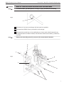
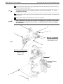
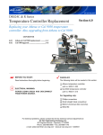
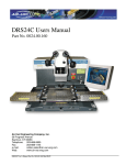
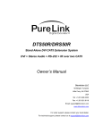
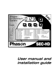
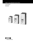
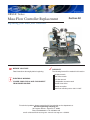
DRS24C Series
Mass Flow Controller Replacement
Section 4.0
Replacing your mass flow controller
☛ BEFORE YOU START:
Read instructions thoroughly before beginning.
ELECTRICAL WARNING:
POWER DOWN DRS24 AND DISCONNECT
FROM POWER SOURCE.
CHECKLIST:
The following items will be needed in this section.
M4 Allen wrench
3/32” Allen wrench
1/8” Allen wrench
8” Adjustable crescent wrench
Slotted screw driver
Needle nose pliers
Mass flow controller part no. 9001.14.007
For technical problems, please contact the Air-Vac technical service department at:
Air-Vac Engineering Company, Inc.
30 Progress Avenue • Seymour, CT 06483
Phone: 203-888-9900 • Fax: 203-888-1145
e-mail: [email protected] • www.air-vac-eng.com • 03/26/01
DRS24 Technical Service Manual
Section 4.0 : Mass Flow Controller Replacement
4.0 Mass Flow Controller Replacement
!
IMPORTANT
VERIFY DRS24 IS DISCONNECTED FROM THE POWER SOURCE.
!
IMPORTANT
WHEN DISCONNECTING A HOSE OR WIRE, BE SURE TO MAKE NOTE OF ITS
LOCATION FOR EASY RECONNECTION.
STEPS:
1
The mass flow controller is part of the pneumatics assembly, located in the left side of the
DRS module (A), (fig.1).
2
Remove the 10/32” button head screw (B), (fig.1), and swing open left box (C).
B
C
Fig. 1
A
NOTE
☛
The remaining steps will be performed assuming you are located behind the DRS24.
3
Loosen screw (D) and swing open computer plate
sub-assembly (E), (fig.2).
D
Fig. 2
E
2
DRS24 Technical Service Manual
!
MARK ALL LOCATIONS WHERE DISCONNECTIONS HAVE BEEN MADE.
REMINDER
NOTE
Section 4.0 : Mass Flow Controller Replacement
☛
To remove hoses, you must push in on ring (F), (fig.3), and then pull out tubing.
Fig. 3
F
NOTE
☛
4
Disconnect air (G), (fig.4), and nitrogen (H) hook-ups from regulators.
5
Disconnect blue diffuser hoses (I) and mark for left and right.
6
Disconnect blue nozzle hose (J) from calibration port, loosen strain relief (K) and pull hose
through plate wall from inside of module, and disconnect nozzle vacuum tube (L) (inside box)
from filter.
Remove site clean (M), probe (N), and pcool (O) vacuum tubes if attached.
K
L
Fig. 4
G
H
J
O
N
M
I
3
DRS24 Technical Service Manual
!
CAUTION
Fig. 5
Section 4.0 : Mass Flow Controller Replacement
7
Disconnect main wire harness at nut.
8
Disconnect ground wire (P), (fig.5), from DRS24 chassis.
9
With two people, tilt machine on its side.
10
From bottom, remove cover plate 8-3/32” allen head screws from under panel.
11
From bottom of DRS24, remove the 4 M4 allen head screws that hold the pneumatics panel in
and remove panel (Q).
USE EXTREME CAUTION WHEN REMOVING SCREWS.
P
Q
4
DRS24 Technical Service Manual
12
NOTE
NOTE
☛
Section 4.0 : Mass Flow Controller Replacement
On the mass flow controller (R), (fig.6), disconnect main wire harness (S), nozzle air hose (T)
and the 2 air inputs (U) and (V).
The black air hose from the nitrogen regulators go to the fitting marked “R” on the
nitrogen/air valve (W).
13
Remove two (2) 3/32” allen head screws (Q) that hold the mass flow controller to the panel (R)
and remove.
14
Reverse these steps to re-install the new mass flow controller.
After installation of the mass flow controller is complete, you will need run the system
software profile “Nozzle Flow Sensor Only” to calibrate the nozzle flow and complete
the installation.
☛
S
U
V
R
T
P
W
Wire List - Flow Switch
#250 white/red = n.o.
#79 white/red = com.
Fig. 6
R
Wire List - Pressure Switch
yellow = com.
middle = open
brown = n.c.
Air
Nitrogen
Y
X
5