1
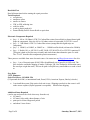
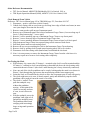
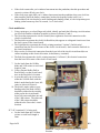
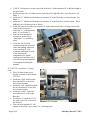
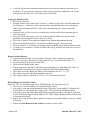
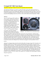
Triumph TR7 TR8 Clock Repair
Greg Bober, Copyright 17 March 2012, Rev 2.7 (originally written 4 July 2005)
The following information is presented as "public knowledge" and is only for the personal use of
individuals who are either restoring or repairing their own Triumph TR7 or TR8 vehicle's clock. The
information may not be used commercially without the consent of Greg Bober (the author), who can be
contacted via [email protected]. Triumph car clubs can reprint this as a monthly newsletter article,
but please Email [email protected] so I know where in the world this has been reprinted. Thanks.
Abstract
The 1975-1982 Triumph TR7 and TR8 car
clocks contain 2 defects that can effect its
successful operation in the vehicle's local
environment. This document describes how
a person with a limited skill level in
electronic component soldering and
automotive vehicle repair can correct these
2 particular defects to obtain a more
reliable Triumph TR7 TR8 vehicle clock.
The first defect, or shortcoming, is that the
clock was designed for approximately a
+25 oC +/–10 oC temperature operation
environment. This was a common
automotive design standard used into the
Picture 1: The TR7/TR8 clock in instrument cluster
mid 1990's by a few major auto companies.
Thus in colder climates, such as 0oC, the clock will just stop. The second defect, is that the clock's
timing mechanism is critically balanced between the force of a timing spring, the electro-mechanical
force applied via an electric coil, the distance a feedback magnet is from a feedback coil, the vehicle's
voltage, the amplification provided by a transistor, the friction of the clock's escapement gears and
many other tolerance items. There is a spot where everything balances, the clock "stalls" and stops
operating. The clock will only start operating again, if the "right" kind of bump in the road (vibration)
or electrical transient (like starting the car) is encountered to jiggle the clock's pendulum back into
motion.
Although I’ve designed analog clocks for the Ford Expedition, Navigator, Jaguar XJC, the modern retro
Mangusta, Lincoln Town Car and a few others using custom parts from Swatch, I choose not to use
those particular Swatch parts. The Swatch parts are still used by many automotive suppliers around the
world for many mass production vehicles, but the parts are not publicly available for sale unless you
rummage through the scrap yards for the dash panel board clocks of the appropriate vehicles. Plus the
Swatch clock motor mechanism only has an hour and a minute hand. I’ve seen others replace their TR7
TR8 clock for little round digital clocks. I wanted to keep the original TR7 TR8 dash appearance and
functionality (hour, minute and second pointers). The provided instructions present how I electrically
modified an original TR7 TR8 to improve the original clock’s reliability while maintaining the original
dash panel appearance.
Page 1 of 9
Saturday, March 17, 2012
Read this First
Read all instructions before starting the repair procedure.
Tools Required:
• screwdrivers
• small nose pliers
• small wire cutters
• 25W to 50W soldering iron
• acid free solder
• wood or plastic tooth pick
• Dremel Hobby Drill or Exacto Knife or equivalent
Electronic Components Required
• Qty = 1, 100 or 110 Ohms 0.25W 5% Carbon film resistor (brown/black or brown/brown/gold
stripe on component). Note: the 100 or 110 ohms resistor is not needed if CD33321 is used.
• Qty = 1, 3.0K Ohms 0.25W 5% Carbon film resistor (orange/black/red/gold stripe on
component)
• Qty = 1, 1N4001, or 1N4002, or 1N4003 or .... 1N4008 rectifier diode (referenced as 1N400x)
• Qty = 1, Holtek 14L, or 14LTO-92, or HT-2014L, HT-2014LTO-92 or CD33321 transistor IC
(This part is hard to find, but easy to install, and works better than alternative parts I've tried.
The “TO-92” describes this component's plastic encasement.)
These parts are available from some electronic stores. Or contact me at [email protected] for a kit:
•
Qty = 1 set of electronic parts $6.00 USD with additional sets of parts $4.00 USD each. The
price includes worldwide shipping (Canada, California, UK, New Zealand is all about the same,
the envelope weighs the most). This can be paid via PayPal to my email address or send a check
to:
Greg Bober
22421 Edmunton
Saint Clair Shores, MI 48080 USA
(US personal check OK, or international bank, Postal, VISA, American Express, Barclay's checks)
•
I can install these parts if the entire clock unit is sent. Shipping costs back to the owner is still
at the owners expense (PayPal payment is acceptable). Email before shipping.
Additional Items Required
(used to test and power the clock when away from the car)
• 9V battery
• 9V battery clips with a short distance of wire
• paint pen or colored finger nail polish
• and about 1 hour of time
Page 2 of 9
Saturday, March 17, 2012
Other Reference Documentation
• TR7 Service Manual, AKM3079B Published by BL Car Limited, 1981 or
• TR8 Repair Operations Manual (ROM), AKM3971, BL Cars Limited, 1980
Clock Removal From Vehicle
Reference: TR7 Service Manual page 454 or TR8 ROM page 351, Procedure 88.15.07
1. Disconnect + positive cable from vehicle's battery.
2. Unbolt clock setting cable at cross beam eye-let along lower edge of dash cross beam (on some
cars it just dangles down into the foot well).
3. Remove center speaker grill on top of instrument panel.
4. Remove top of instrument panel fascia above Instrument Gauge Cluster (4 screws along top of
fascia, 3 along bottom edge, 7 screws total).
5. Remove 2 screws attaching top rear of Instrument Gauge Cluster to top fascia panel.
6. Remove 3 screws from top edge of Instrument Gauge Cluster lens.
7. Remove 2 screws attaching bottom of Instrument Gauge Cluster to knee level fascia panel.
8. Slide Instrument Gauge Cluster lens upward along curved contour of dash fascia.
9. Pull black plastic mask toward steering wheel.
10. Remove the two screws attaching the clock to the Instrument Gauge Cluster housing.
11. Remove clock by pulling clock forward toward steering wheel 5cm or few inches.
12. Disconnect clock time setting cable (knurled nut) from behind the clock unit.
13. Note: it is not necessary to remove the Instrument Gauge Cluster from the vehicle nor it is
necessary to pull out or remove clock setting cable completely.
Pre-Testing the Clock
• With a battery clip, connect the 9V battery's + terminal to the clock's rear flat terminal and the
9V battery's – terminal to clock's metal housing or threaded bolt above the clock setting cable
connection shown in Picture 2 (the clock’s metal housing isn’t always electrically connected).
• Note: one end of the clock's pendulum can be seen by looking under the metal cover shown in
Picture 2 (look through the gap between the metal housing and the brass support post).
• Orient the clock as if installed in the vehicle to allow the escapement gear to work with gravity.
• The clock might start on its own; if already started, gently and deliberately stop the clock's
pendulum with a tooth pick near the center of its swing.
• The clock is “stalled” if one
pulls the toothpick away
without the pendulum
moving. At this point if the
clock was moving, and now
it’s not, it can’t start on its
own.
• With the toothpick, move the
pendulum 3mm right or left,
and pull the toothpick away.
The pendulum should start
swinging with increasingly
larger swings until operation
resumes.
Page 3 of 9
Picture 2: 9V battery test set up
Saturday, March 17, 2012
•
•
•
If the clock restarts after you've induced movement into the pendulum, then this procedure and
corrective action will help your clock.
If the clock stops again after you've induced movement into the pendulum, then your clock has
other troubles (check the battery connections, broken clock spring, broken coil(s), etc.)
I noticed that if the clock makes a small clanking and clunking sound, it’s the escapement gears
binding (often loosens up after 30 seconds, 1 or 2 clock ticks).
Clock modification
1. Using a paint pen, or colored finger nail polish, identify and mark the following circuit locations
(or at least be familiar with these locations) as shown in Pictures 3 and 4.
2. The Green dot represents the clock's Ground (lower right most electrical connection on the
clock's circuit board).
3. The Purple dot represents the clock's feedback bias (this appears as a diagonal circuit trace from
the lower corner of the circuit board).
4. The Light Blue dot represents the clock's existing transistor's "emitter" (2nd electrical
connection from the lower left corner of the clock's circuit board)—don't count the little hole in
the circuit board trace.
5. Skip over the 3rd electrical connection from the lower left of the clock's circuit board (do not
connect anything to this electrical location, its the Battery+ terminal).
6. The Red dot represents the clock's existing transistor's "collector" (4th electrical connection
from the lower left corner of the clock's circuit board).
7. Cut the leads from the 1N400x
diode and 3.0K resistor so each lead
length is 3mm.
8. Using a Dremel Hobby Drill or
Exacto Knife, cut the circuit board
trace at the Purple dot’s location.
9. Across this newly cut circuit trace,
solder the 1N400x diode with the
diode's anode band to the lower left
corner as shown in Picture 4.
10. The diode's anode (white or gray
banding end of the diode’s body)
should be soldered to the existing
solder pad in the circuit board's
lower left corner and share one end
of the 3.0K resistor. The other end
of the 3.0K resistor should be
soldered to the Green dot’s circuit
location.
Picture 3: Location and marking the locations noted
IF "14L" transistor IC is being used:
• Cut the leads from the 110 Ohm
resistor so each lead's length is
2mm.
Page 4 of 9
Saturday, March 17, 2012
Picture 4: Temperature Compensation Diode and
Resistor
•
•
•
•
•
•
•
If 14L IC is being used, cut the center lead of the new 3 leaded transistor IC to half the length of
the outer leads.
Solder one end of the 110 Ohm resistor vertically to the Light Blue dot’s circuit location. See
Photo 5.
Solder the "G" labeled lead from the new transistor IC to the Green dot’s circuit location. See
Photo 5.
Solder the "V" labeled lead from the new transistor IC to the Red dot’s circuit location. This is
hidden by the 110 Ohm resistor in Photo 5.
Solder the center lead of the new transistor IC to the unused end of the 110 Ohms resistor (the
center lead is sometimes
marked as “L”, and sometimes
mark “O” see Picture 5).
Note: the new transistor IC
will operate as the clock's
“pace maker” or “watchdog
timer”.
Verify the 3rd electrical
connection from the lower left
corner has nothing connected
to it or touching it. If an
accidental connection is made
to this location, the
components will “smoke”
when powered and the clock’s
coil will become un-repairable
(I learned from making this
Picture 5: 14L transistor IC added
mistake).
IF "CD33321" transistor IC is being
used:
• The 110 Ohm resistor is not
needed, a resistor is built into the
CD33321.
• Solder the "right" lead from the
new transistor IC to the Green
dot’s circuit location.
• Solder the "left" labeled lead from
the new transistor IC to the Red
dot’s circuit location.
• Solder the "center" lead of the
new transistor IC to the Light
Blue dot.
• See Picture #5, orient the 33321
the same as the 14L as shown in
Picture 6: 33321 added
the Picture 5.
• Note: the new transistor IC will
operate as the clock's “pace maker” or “watchdog timer”.
Page 5 of 9
Saturday, March 17, 2012
•
Verify the 3rd electrical connection from the lower left corner has nothing connected to it or
touching it. If an accidental connection is made to this location, the components will “smoke”
when powered and the clock’s coil will become un-repairable.
Testing the Modified Clock
• Refer back to Picture 2.
• Through a battery clip, connect the 9V battery's + terminal to the clock's rear flat terminal and
the 9V battery's – terminal to clock's metal housing or threaded bolt above the clock setting
cable connection shown in Picture 2 (the clock’s metal housing isn’t always electrically
connected).
• Orient the clock as if the clock were installed in the vehicle to allow the escapement gear to
work with gravity.
• The clock will be able to start on its own; if already started, deliberately stop the clock's
pendulum with a toothpick near the center of its swing.
• The clock is "stalled" if one pulls the toothpick away without the pendulum moving.
• The newly installed transistor IC will make the pendulum wiggle 1 time per second.
• The new transistor IC will induce increasingly larger pendulum swings until operation resumes.
• It can take a few seconds to 1 minute to build up the energy needed to overcome any friction in
the pendulum.
Debug, Possible Mistakes
• If operation doesn't begin, or no movement is detected, check component orientations.
• Make sure the battery isn't dead or voltage under 8V (my clock worked OK with 8.7V).
• Check the polarity of the newly added diode.
• Check all newly added solder joints.
• With an ohm meter, the added 3.0K Ohms resistor should read as 1800 Ohms (the 3.0K is in
combination with another clock resistor yielding the 1800 Ohms measurement).
• The voltage across the added 3.0K Ohms resistor should be near 1.1V +/- 0.1V.
• The voltage across the added diode should be near 0.6V.
• The voltage at the new transistor IC's "left" or "V" leg should be the same.
Re-Installation of Clock Into Vehicle
Reference: TR7 Service Manual page 454 or TR8 ROM page 351, Procedure 88.15.07
1. If necessary, Clean the inside of the Instrument Gauge Cluster.
2. If necessary, clean and polish Instrument Gauge Cluster lens (I used Mother's California Gold
Scratch Remover, most automotive supply stores "will" have this or something similar).
3. If necessary, renew the foam rubber strips along top and bottom edges of the lens (I used "Soft
Touch" Ultra Heavy Duty Felt with Adhesive 1/2" Wide Strip by Waxman #2200 obtained from
a home hardware store).
4. Inspect the second, minute and hour pointers to insure no accidental bending occurred, re-flatten
if necessary.
5. Follow the Clock Removal From Vehicle procedure in reverse order.
Page 6 of 9
Saturday, March 17, 2012
Done!
Pat yourself on the back and go for a road trip.
Clock Test Data
(sample size = 1, my own TR7 clock testing both CD33321 and 14L versions)
• pendulum cycle rate, 2.5Hz or 400mS
• over 18 Hr period the "14L modified" clock showed no loss of time accuracy
• the clock self started from "stalled" position and operates at 8.5V @+25 oC or 75 oF
• the clock self started from "stalled" position and operates at 11.0V @-12 oC or 10 oF
• "original" clock operating current near 4.7mA, "14L modified" clock operating current about
5.7mA average @12V
• if 0 Ohms with 14L is used instead of 110 Ohms, operating current > 6.5mA time averaged
• if 300 Ohms with 14L is used instead of 110 Ohms, the force from coil can't overcome extra
friction from frost
• the CD33321's operating current is 1mA less than 14L transistor IC operating current
Theory Behind The Operation and Modifications
Normal Clock Operation:
When the voltage is applied to the clock unit, a bias voltage is applied to one end of
a feedback coil under the pendulum. This bias voltage will always be about 13% of the
vehicle's voltage. The other end of the feedback coil is connected to an NPN type transistor.
The transistor drives another coil under the pendulum to make the pendulum swing against the force
from the clock's timing spring. When the pendulum swings in the direction pulled by the
clock's timing spring, the magnet on the pendulum induces a >0.1V drop in the feedback coil and
thus the bias voltage lowers enough to turn the transistor "off". When the pendulum motion stops
the transistor turns back "on" and pulls the pendulum back until the clock's timing spring will
not allow additional travel. During this motion, the magnet on the pendulum induces >0.1V additional
voltage in the bias to turn the transistor "on" harder to allow the coil to pull the clock's
spring out as far as possible. When the spring has traveled as far as possible, the added
bias voltage is no longer given, the transistor begins to turn "off", and the pendulum motion
reverses direction restarting the swing cycle. Each swing cycle will allow the escapement gear
mounted on the pendulum shaft to "tick" or count one 400mS moment of time.
Temperature (and Voltage) Compensation
The NPN drive transistor has a PN Silicon alloy "junction" (example: one part might be Silicon mixed
with a tiny bit of Aluminum and the other being Silicon mixed with a tiny bit of something else). When
there is more than 0.6V @ 25 oC across this junction (the transistor's "base" and "emitter" pins) the
transistor's "collector" and "emitter" junction will activate to conduct current. Relative to this basic
NPN transistor characteristic, the TR7 clock has two problems: 1st, as the vehicle voltage changes over
engine RPM, environmental temperature and electrical loading, the 13% bias voltage changes. But the
clock spring's tension force capability doesn't change; 2nd, the transistor's PN junction changes about
0.0024V for each degree Celsius of temperature change. At hot and cold temperatures the transistor's
"on and off" thresholds change significantly, especially when it’s 0 oC or 40 oC. By installing a diode
with a similar junction into the bias voltage circuit, the bias voltage will shift up and down with
Page 7 of 9
Saturday, March 17, 2012
ambient temperature almost identically to any temperature shifts experienced by the clock's transistor.
Also, since the diode's voltage drop of 0.6V will be almost constant, it will make the feedback bias
voltage 50% less dependent or sensitive to the vehicle's system voltage. The added resistor adjusts the
bias voltage back to the original clock's bias voltage point.
Pace-maker or Getting a Kick Start
If there is no motion in the pendulum, then there isn't an adding or subtracting voltage being induced
into the feedback coil to turn "on and off" the transistor. This "stalled" location in the pendulum's
swing is where the electro-motive force from the transistor-driven coil matches the clock's timing
spring's tension force resulting in no motion. The modification is to add a low voltage oscillator to
disturb the balancing forces and toggle the transistor "on" and "off" to induce some motion into the
pendulum. The normal operating cycle of the clock's pendulum will be restored once there is sufficient
motion for the feedback magnet to induce the addition or subtraction of bias voltage to the bias circuit
controlling the transistor's "on" and "off" toggling.
Acknowledgements
Special thanks goes to James TenCate, Odd and Lena Hedberg for proof reading this article, adding
TR8 Service Manual Reference information and a new Photo #1, a sharper image of Photo #3 and a
new Photo #6 with the CD33321.
Biography
Sorry can’t find a picture of me, but here’s my TR7.
I’ve been a part of designing automotive electronics since 1986. Since 2008 I’ve been working for
LG-Chemical on Lithium Ion battery storage systems for commercial truck and passenger vehicle
applications. My prior experiences have been with Ford Motor Co. and Visteon Electronics.
Page 8 of 9
Saturday, March 17, 2012
To my credit, I’ve designed the control electronics for many different suspension / steering control
modules, body illumination modules, dash panel clocks, and multi gauge instrument clusters (examples
are Thunderbird Super Coupe Shock/ Steering module, Lincoln Mark 8 Shock Module, Jaguar XJC
clock, Jaguar ‘S’ Class cluster, Lincoln LS cluster, Nissan Quest/Mercury Villager cluster, plus more).
From 2002 to 2005 I restored the above a California EFI type TR7 Spider using many methods of
improvement applied to current production vehicles for electrical power distribution and fusing
strategies. The CD player, electric radiator fan, Honda RSX seats and Bosch alternator are the only
non- TR parts installed on the car. This TR7 now has reliability similar to that of a new car, I
sometimes drive it to work (70 miles round trip). For the curious, the vehicle gets 30MPG on mixed
city / hiway driving.
Page 9 of 9
Saturday, March 17, 2012