1
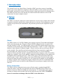
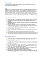
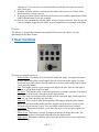
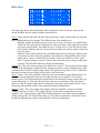
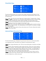
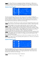
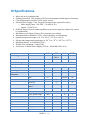
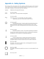
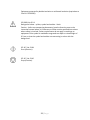
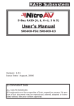
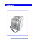
LDDC (Laser Diode Driver Controller) Operators Manual Version 1.3 Lumina Power, Inc. 26 Ward Hill Ave. Bradford, MA 01835 Phone: (978)241-8260 Fax: (978)241-8262 www.luminapower.com 1-1 | P a g e Table of Contents 1 Introduction.......................................................................................................................... 1-3 2 Setup .................................................................................................................................... 2-3 Power .................................................................................................................................. 2-3 Driver Connection ............................................................................................................... 2-3 Communication ................................................................................................................... 2-4 USB ................................................................................................................................. 2-4 Ethernet ........................................................................................................................... 2-5 3 User Controls ....................................................................................................................... 3-5 4 Display/Indicators ................................................................................................................ 4-6 5 Menu Information ................................................................................................................ 5-6 Verification Page ................................................................................................................. 5-6 Main Page ........................................................................................................................... 5-7 Pulse Mode Page ................................................................................................................. 5-8 Interlock Status Information Page ........................................................................................ 5-8 System Setup Page #1.......................................................................................................... 5-9 System Setup Page #2.......................................................................................................... 5-9 Save/Recall Settings Page .................................................................................................. 5-10 Information Page ............................................................................................................... 5-11 6 Driver I/O Connection ........................................................................................................ 6-12 7 Command Set ..................................................................................................................... 7-13 Device Command Format .................................................................................................. 7-13 Device Addresses .............................................................................................................. 7-13 Command Types................................................................................................................ 7-13 Control Commands ........................................................................................................ 7-13 Query Commands .......................................................................................................... 7-14 LDDC Command Summary............................................................................................... 7-14 System State Return........................................................................................................... 7-15 8 Basic Setup and Operation ................................................................................................. 8-16 Remote Operation Using Commands ................................................................................. 8-16 Remote Operation Using Software GUI ............................................................................. 8-17 9 Analog Measurement ......................................................................................................... 9-18 10 Specifications ................................................................................................................. 10-19 Appendix A - Safety Symbols ............................................................................................. 10-21 Appendix A - Lumina Power Driver Connections ..................................................................... 23 Appendix C CE Declaration of Conformity ............................................................................... 25 1-2 | P a g e 1 Introduction The Lumina Power Laser Diode Driver Controller (LDDC) provides a means of controlling various types of laser diode driver supplies. It allows the ability to easily control current levels, pulse modes, and interlock controls as well as monitor voltage and current levels from the driver. The LDDC provides an easy user interface for manual control and readout as well as USB connectivity for remote computer control. 2 Setup The LDDC can easily be connected to a laser diode driver. In most cases a simple cable is all that is required to interface with the driver and provide power to the unit. If the equipment is used in a manner not specified by the manufacturer, the protection provided by the equipment may be impaired. Figure 1 (LDDC Connections) Power The LDDC requires a 15-24VDC (200mA) power supply to operate. The included wall adapter can be used to power the unit. The power adapter should be plugged into the rear panel of the unit that is labeled 15VDC. If a different power source is used, the required mating connector is a standard, circular female plug with the following dimensions: 5.5mm x 2.1 mm x 12mm (outer diameter x inner diameter x connector length). A power switch on the rear of the unit will turn on the controller. The controller can also be powered directly from some driver supplies that have an auxiliary DC output of at least 15V @ 200mA on pins 13 or 14 of the interface connector. Please refer to the operator’s manual of the laser driver supply to verify if an auxiliary supply pin is available. Power can be applied by both the wall adapter and the driver supply since the supplies will be internally protected. If the 15VDC power is derived from the Driver I/O connector pins 13 and 14 and the voltage source is not self-limiting to less than 8A, the supply line must be limited by means of fusing it at 5A. All Lumina power supplies are self-limiting so no fusing is required. If an external power supply is chosen to be used, it is recommended that the mains outlet be easily accessible so that the plug of the external power supply can be easily removed. Driver Connection The LDDC to driver connection in most cases will only require a straight through DB15 connection. Please verify that your particular driver has a compatible pin out. Refer to the Interface Connection Table for detailed pin out descriptions. A custom cable can be made if necessary to connect to drivers that do not use the same pin outs as the LDDC. WARNING, incorrect connections can damage either the LDDC or the diode driver. 2-3 | P a g e Communication The LDDC provides a standard USB connection for remote communications. An optional Ethernet connection is also available. USB When the LDDC is connected to a remote computer via the USB connection, the computer will recognize the unit as a “LDDC Controller”. Drivers will need to be installed for the remote computer to interface to the LDDC. Drivers are included on the provided CD. Once the drivers have been installed, the LDDC will show up in the device manager as a USB to Serial Port Adapter. The LDDC can then be communicated with by using any terminal program. The unit is baud rate independent, so any speed can be selected. Typically a rate of 115,200bps can be used. Driver Installation (Windows XP) 1. Plug the LDDC into the computer using a USB cable. Make sure the unit is powered on. 2. The computer will pop up a message indicating it has found new hardware: “LDDC Controller”. 3. The new hardware wizard will launch. Check the “Install from a list or specific location” option and click next. 4. Then select “Search for the best driver in these locations” and check the option to “Include this location in the search”. Then click the browse button and locate the folder on the CD where the LDDC drivers are located. Click next. 5. A message window will launch asking if you want to continue installing this driver. Select the “Continue Anyway” button. 6. It should now indicate that it is installing a driver for a “LDDC USB Communications Port”. 7. A message should then indicate that the drivers have been successfully installed. 8. You can now communicate with the LDDC using a Com port selection. You can view the Com port number assigned to the LDDC in your computers device manager under Ports. Driver Installation (Windows 7) 1. Plug the LDDC into the computer using a usb cable. Make sure the unit is powered on. 2. The computer will pop up a message indicating it has found new hardware and is installing device driver software. 3. A message will then indicate that the device drivers have not been successfully installed. The Action Center may then launch with a list of options. Close the Action Center and do not launch any of the actions. 4. Go to your computers device manager. This can be done by either right clicking on the desktop “My Computer” icon and selecting properties, then Device Manager on the left toolbar or goto Control Panel and then Device Manager. 5. In Device Manager you should see a device under the Other Devices called the LDDC Controller. There will be a yellow exclamation point next to it. 6. Right click on the LDDC Controller and select update driver software. 7. Select Browse my computer for driver software and browse to the location of the USB drivers for the LDDC. Typically found on the software CD. It will contain a file called 2-4 | P a g e “lddccdc.inf”. You only have to select the folder in which the file resides, not the file itself. Click next. 8. Windows will then indicate a warning window that the drivers are not verified. Select Install this driver software anyway. 9. A message will then indicate that the drivers have been successfully updated and a LDDC USB Communication Port is now available. 10. You can now communicate with the LDDC using a Com port selection. You can view the Com port number assigned to the LDDC in your computers device manager under Ports. Ethernet The Ethernet is an optional communication method. Please contact the factory for more information on this future feature. 3 User Controls Figure 2 (User Controls) The main user controls consist of: - Enable/Disable. This button is used to initially enable the supply. On supplies that have both an enable and a pulse control signal, this will activate the enable signal. On units that do not have pulse control, this will enable the activation of the enable control signal via the start/stop button. - Page. This button is used to cycle through each page on the unit. Once the final page is reached, it will go back to the first page. - Up Arrow. This button is used to increment parameters or change selections. The amount the parameter is increased is dependent on the digit position. - Next. This is used to navigate to the next line item in a particular page. Some pages may have only one item and others may have four. - Start/Stop. This is used to either initiate pulsing of the supply using the pulse control signal or it will activate the enable signal for supplies that do not have a pulse control. The start will only become “active” once the enable condition has been activated. - Left Arrow. This button will allow you to move the cursor to the next most significant digit to the left. - Down Arrow. This button is used to decrement parameters or change selections. The amount the parameter is decreased is dependent on the digit position. - Right Arrow. This button will allow you to move the cursor to the next least significant digit to the right. 3-5 | P a g e - Encoder/Selector. This rotary encoder can be used to increment or decrement parameters or toggle between item selections. The amount of the increment/decrement is based on the digit position. Pressing the encoder knob has the same function as the next button to advance to the next menu line item. 4 Display/Indicators The following are used for user indicators and information: - A 4 line x 16 character LCD backlit display. This display will show various information depending on the active screen. - 3 indicator LEDs. An Enabled indicator (Blue) shows when the unit is in an enabled state, ready to fire or start pulsing the supply. An Active indicator (Green) shows when the unit is actively allowing the supply to fire. A Fault indicator (Yellow) will indicate if any open interlock or fault condition has occurred. 5 Menu Information The following describes the various LCD menu pages and operation of each item on the pages. Any menu parameter shown inside brackets designates the potential to be navigated to and manually altered. Verification Page Ve r i f y S e Max I : 40 D r i v e r : Cu s A n y Ke y t o t up ! Am p s t om C o n t. This verification page is a warning to be sure that your maximum current setting and the driver selected is correct. This maximum current setting can be verified or changed on the System Setup #1 page. The driver can also be verified on the first setup page. Press any key to advance the page to the main display. The next page displayed after pressing any key will be the first setup page so you can verify that the correct setup is selected. WARNING: If the maximum current does not match the driver you are controlling then unexpected current levels may be driven if not careful. This could possibly damage the laser diode. 5-6 | P a g e Main Page Status : I Se t : I Me a s : V Me a s : Di 05 05 10 s . . . ab l ed 00 A 00 A 00 V The main page shows status information, allows adjustment of the set current, measures the current feedback and the voltage feedback from the driver. Line 1: Status indicator line that will show the system status, which would include any interlock faults, enabled and actively running. The different status items displayed are: - Disabled. Neither the enable state or the fire state is active. The unit is in a disabled state. - Enble-Off. The unit has been enabled and is ready to be fired. If the supply has an enable and a pulse control ability, the enable line (pin 1) will be active. If the unit does not have pulse control cababilty, then the unit is just in an enabled state and the enable control line is not yet active. - Enble-On. This indicates that the unit is enabled and is actively firing (providing current to the diode). In units with pulse capability, the enable line is high and the pulse control signal (pin 8) is active. In units with only enable control, the enable line is now active. - Fault. A system fault has occurred. Currently this means that an over-temp condition has occurred. The Fault LED indicator will also be illuminated. Line 2: I Set. This is the current setting to the diode driver on pin 7. The resolution of the setting is based on the adjustment resolution and the maximum current set in the calibration page. This controls the level of the I Program output signal. The signal will vary from 0-10V to control the amount of current the power supply will provide to the laser diode. Line 3: I Meas. This is the measured current from the current monitor signal from the driver on pin 6. The current displayed is based on a reading from the power supplies 0-10V current monitor signal. This is then displayed in amps based on the maximum current setting value. See System Setup Page #1. When in CW mode, this value is read continously. When in a pulsed mode, the value is sampled right after the rising edge of the pulse control signal. Please refer to the Analog Measurement section of the manual for details and limitations. Line 4: V Meas. This is the voltage measurement from the compliance voltage or terminal voltage of the driver on pin 5. The voltage displayed is based on a reading from the power supplies 0-10V voltage monitor signal. This is then displayed in volts based on the compliance voltage setting value. See System Setup Page #1. This value is continously read. Please refer to the Analog Measurement section of the manual for details and limitations. 5-7 | P a g e Pulse Mode Page M od e R at e Wid t h C ou n t : : : : CW 00 0010 . 0 0 . 0100000 00 100 The pulse mode page allows you to setup the type of pulse control that will be utilized. It also allows you to control the pulsed repetition rate, desired pulse width and number of burst counts (if in burst mode). Line 1: Mode. This will set the system firing mode. Options include: Continuous Wave, Pulsed, Burst, or Single Shot. If the unit is set to have pulse control disabled, then only CW mode will be available and the remaining pulse options will be unavailable. See System Setup #2 page. Line 2: Rate. This sets the repetition rate (in Hz) when in pulsed or burst mode. The maximum rate is dependant on the max rate setting on System Setup #1 page. Line 3: Width. This sets the pulse width (in seconds) of the triggering pulse to the driver when in pulsed, burst or single shot mode. The width adjustment will be limited to a maximum of roughly 90% of the rate period. Line 4: Count. This sets the number of shots when in burst mode. The unit will pulse this number of times when in burst mode. Interlock Status Information Page S t a t us : Di s ab l ed I n t e r l o c k : Op e n C r owb a r : Op e n O v e r T e m p : OK The status information page will display the general system status, the crowbar status and the over termperature status. It also allows you to adjust the external interlock control. Line 1: Status. Stautus information screen. This is the same information as described on the Main Page. Line 2: Interlock. This is an interlock control output to the driver. When set to On, the interlock on the driver is satisfied. This means that the output of the connection pin 3 is pulled to ground which will satisfy the supply interlock input. When set to Off, it is open. See System Setup #2 page if you wish to have this interlock control satisfied by default. You must satisfy the power supply interlock input in order to enable the ouput current control. Line 3: Crowbar. This is the Crowbar Status from the diode driver (Pin #2). When a no load condition is detected, the driver shorts the outputs. This will indicate if this is shorted or ok to run. Not all diode drivers will have this status. 5-8 | P a g e Line 4: Over Temp. This is the over-temperature indicator read from pin 11. When an over temperature condition is sensed, the fault indication will be set. If the supply does not have an overtemperature signal, this can be bypassed by changing the settings on System Setup #2 page. System Setup Page #1 D r i v e r : Cu C Vo l t a g e M a x i mum I Max Ra t e s t om : 10 . 0 : 010 :000100 The first system setup page allows you to select the type of driver you have and adjust the expected compliance voltage and current ranges from the driver the LDDC is controlling. Please refer to the diode driver data sheet for these values. This setup page also allows you to set a maximum pulsed rate if the driver or diode has a limitaion on the frequency of the pulsed rate. These values can be stored for later recall in the save/recall page. Line 1: Driver Selection. This allows you to select various types of Lumina Power drivers. Once a driver has been selected, various features and functions may be enabled or disabled depending on that models capability. If you are using a model not listed, select the “Custom” option. Line 2: C Voltage. This is the compliance voltage calibration setting. Each driver can have a specific compliance voltage that is part of the model number. The measured compliance voltage on the main page is based off this value. If your supply provides a direct one to one output of the compliance voltage, then the compliance voltage calibration can be reduced to zero or set to a value of 10. When set to zero, you will see a “Direct” indication on the display. Line 3: Maximum I. This is the maximum current (in amps) output of the driver connected to the controller. This depends on the driver model and wattage. The current setting on the main page is based on this maximum value. You will also see a warning screen when the controller is first powered up verifying this setting. Line 4: Max Rate. The maximum repetition rate (in Hz) when in continuous or burst mode. This should be set to whatever the driver maximum pulsed repetition rate is. The active rate cannot be adjusted higher than this value. System Setup Page #2 S T I P e t up #2 e mp F a u l t : E n n t l k Cn t r l : En u l s e E n a b l e : On The system setup page #2 allows you to setup interlock default states and whether or not the LDDC should allow pulsing of the driver. Please refer to the diode driver data sheet for the specific interlock options and whether or not it supports pulsed modes. These values can be stored for later recall in the save/recall page. Line 1: Indication of System Setup #2 page. No function. 5-9 | P a g e Line 2: Temp Fault bypass. This will allow you to bypass the over temperature fault input on pin 11. Options are either En (enable) or Byp (Bypass). Not all drivers have the temperature fault indication so this allows that input to be ignored. Line 3: Intlk Cntrl. Interlock control bypass. This will allow you to bypass the manual operation of the interlock control on the Status Information Page. When set to Byp (bypass), the interlock will automatically be enabled on power up. The default setting is En (enabled). When enabled, you must manually operate the interlock control on the Status Information Page. Line 4: Pulse Enable. This setting will turn on or off the pulsing capability of the controller. Since not all drivers can be pulsed or utilize a pulse control signal, this function can be enabled or disabled. The default is on. Once the pulse control has been disabled, the only mode available on the Pulse Mode Page will be CW. Once the pulse control has been disabled, the enable control signal will be activated (high) when the controller is first enabled and then started by pressing the start button. Save/Recall Settings Page Sa S to S av E xe v e / Re c a l l rage Bin: 1 e / R e c a l l : R cl cut e : < or > The Save/Recall page allows you to store all the setup and general settings into storage “bins” or locations. These are saved in non-volitale memory for recall at later times. The last stored bin number will be the one recalled when the unit is powered back on. NOTE: whenever a bin is recalled, the unit will be taken out of enabled and active mode along with reducing the set current to zero. This is for safety reasons in case the recalled parameters are incorrect for the type of driver or laser diode. Line 1: Indication of Save/Recall page. No function. Line 2: Storage Bin. This selects the desired storage bin for recalling from or saving to. There are 5 storage locations from 1-5 to select from. All calibration and system settings will be recalled or stored to the selected bin number. Line 3: Save/Recall. This selects the action to perform, either a save or recall. Line 4: Execute. This will execute the action or either recalling or saving to the selected storage bin. Pressing either the left (<) or right (>) arrow buttons will initiate a save or recall action. 5-10 | P a g e Information Page L u m i n a P ow M o de l : 1 F i rm w a r e : 0 S er i a l #:1 er 550 . 19 234 The information page displays general information about the LDDC unit. Line 1 & 2: Company information. Line 3: Model number of the LDDC. Line 4: Firmware version number. 5-11 | P a g e 6 Driver I/O Connection The main interface connection to the diode driver supply utilizes a standard 15 pin D-Sub male type connector. Number Name Type Description Range 1 Enable Output TTL output to enable diode driver output section 0V = Off 5V = On 2 Status Crowbar Input Indicates status of crowbar shorting clamp on output. 0V = Crowbar Off 5V = Crow On 3 Interlock Control Output Open collector output pulled to ground when activated 15V max @100mA sourcing. 4 GND Ground Signal Ground 5 V Monitor Input 0-10V with 0.01V resolution. 6 I Monitor Input Analog input corresponding to driver compliance voltage level Analog input corresponding to driver current output 7 I Program Output Current level adjustment 8 Pulse Control 9 GND Output Pulsing control 0-10V with 0.0024V resolution. 0V = On 5V = Off Ground Signal Ground 10 N/C 0-10V with 0.01V resolution. Reserved – No connection 11 Over Input Over temp input from driver. Temperature 12 N/C Reserved – No connection 0V = Ok 5V = High Temp 13 +15VDC Input 14 +15VDC Input 15 GND +15V @ 200ma Power Input Power Input Ground +15V @ 200ma Power Ground 6-12 | P a g e 7 Command Set The LDDC communicates via a standard USB type B connection. The unit operates in a serial emulation mode in which the host computer will recognize the LDDC controller on a serial port. Device Command Format All commands use ASCII characters and are composed of the following fields: <Prefix><Address><Deliminator><Command String>[Parameters]<Terminator> Field Description Prefix Single semicolon character ";", must precede all commands. The device will reset its command input buffer when the prefix is received. Address 2 ASCII characters. Each device has a unique address which is programmed into its firmware. See the table below for a list of addresses. Deliminator Single colon character “:”, must follow device address. Command String Commands are specific to each device -- see the following sections for the commands that each device supports. Parameters Terminator (optional field) Some commands may have parameters which are separated by spaces follow the command string. Multiple parameters are also separated by spaces. To query a command parameter, append a “?” to the end of the parameter (no space). ASCII carriage return character (decimal value 13). The receiving device does not process any commands until the terminator is received. Device Addresses Address Device DC Diode Controller. Command Types There are two types of commands -- those that set a value or initiate an actions (control commands), and those that request information (query commands). Each device must respond in the proper manner to each type of command. Control Commands A device must always parse a control command and return a response immediately. If the command is a recognized command and the parameter is valid, then the device returns an "OK<CR>". (<CR> = ASCII carriage return, decimal value 13). If the command is not recognized by the device, then it responds with "?1<CR> If the command is recognized, but the parameter value is missing or invalid, then the device responds with a "?2<CR>". 7-13 | P a g e If the command is recognized, but the parameter is out of range, then the device responds with a “?3<CR>”. If a control command is received while the device is in the midst of executing a previous command, and the commands are mutually exclusive (cannot be executed in parallel), then the previous command is aborted and the new one executed. It is up to the host controller (the PC) to poll the device and make sure the previous command is finished, if that is the needed. Query Commands Query commands return a value to the PC as soon as the command is parsed and executed. The value returned will depend on the command. The response is always terminated with a <CR>. If a query command is not recognized by the device, then a "?0" is returned. LDDC Command Summary Address Command Parameter Query Response Description Diode Controller address which is required before any/all subsequent commands. ;DC :BC 1 - 65535 :CB? :CM? 1-65535 Sets and/or queries the burst count feature. 0 = Open 1 = Closed 0 to max current(up to 3 decimal places) Query Only. Returns the Crowbar status. 0 - Max Current Sets and/or queries the Current Setting (Up to three decimal places). 0 - 99 Sets and/or queries the Compliance Voltage (Up to one decimal place). Sets and/or queries percentage duty cycle of pulsed output. Sets and/or queries the Enable signal. Bypasses and/or queries the external interlock control so it is always in a closed or shorted state. Sets and/or queries Interlock Control feature. Identification. Will return an identification string in the format of “Company,Model,Serial number,Firmware version”. :CS 0 - Max Current :CV 0 - 99 :DC 0.0001 – 90 0.0001 – 90 :EN 0 or 1 :IB 0 or 1 0 = Disable 1 = Enable 0 = Disable 1 = Enable :IC 0 or 1 :ID? 0 = Open 1 = Closed Ex: Lumina Power,1550,1234 ,0.21. 1 - 999 :MC 1 - 999 7-14 | P a g e Query Only. Returns the Current Measurement. Sets and/or queries the Maximum Current (Refer to the Diode Driver for confirmation). :MR 1 - 100000 :OT? :PE 0 or 1 1 - 100000 Sets and/or queries the system's Maximum Rate. 0 = Okay 1 = Fault 0 = Disable 1 = Enable Query only. Returns the Over Temperature status. Sets and/or queries the pulse mode enable function. :PM 0, 1, 2, 3 0 = CW 1 = Pulsed 2 = Burst 3 = Single :PW 200ns - 90% of Rate 200ns - 90% of Rate Sets and/or queries the system's Pulse Width. 1-5 Recall storage bin. Will recall the settings in the specified user storage bin. 0.1 - 100000 Sets and/or queries the system's Repetition Rate. 16 bit decimal Query Only. Returns the System's State. See the System State section below for return states. :RC :RR 1-5 0.1 - 100000 :SS? :ST 0 or 1 :SV 1–5 :TB 0 or 1 :VM? :VN? 0 = Disable 1 = Enable 1–5 Sets and/or queries the system's Pulse Mode. Sets and/or queries the Start signal. Save settings to specified storage bin. 0 = Disable 1 = Enable Sets and/or queries the temperature interlock bypass mode. 0 – Compliance Voltage Query Only. Returns the Voltage Measurement (Up to 3 decimal places). Ex: 1.2 Query Only. Returns the system Version Number. System State Return The system state return is represented by a 16 bit binary number in which only the first 6 bits are utilized. As seen below, each bit represents an individual state (Crowbar status, Interlock status, etc.). Upon sending the System State query command, a decimal representation of the binary status bits will be returned. Example 1: Crowbar = Closed, Over Temp = OK, Interlock = Closed, Fault = No Fault, Ready = 0, Active = Stop, Enable = Active 1010001 = 81 Example 2: Crowbar = Open, Over Temp = Fault, Interlock = Open, Fault = Fault, Ready = 0, Active = Stop, Enable = Inactive 0101000 = 40 7-15 | P a g e 6 5 4 3 2 1 0 Crowbar Over Temp Interlock Fault Ready Active Enable 0 = Open 1 = Closed 0 = OK 1 = Fault 0 = Open 1 = Closed 0 = No Fault 1 = Fault 0 = Not Ready 1= Ready 0 = Stop 1 = Start 0 = Inactive 1 = Active 8 Basic Setup and Operation The LDDC has multiple functions and parameters which provides the potential for a number of modes of operation. The following sections will outline a sequential list to be carried out regarding basic start-up and operation pertaining to different scenarios: Remote Operation Using Commands The first example will concentrate on remote communications-based (via USB) operation that requires the Diode Driver to supply power at a constant level while utilizing the Interlock Control and Pulse Mode features. 1. 2. 3. 4. 5. 6. First, ensure required USB drivers are already installed. Connect the LDDC to the remote communications computer via USB. Connect the LDDC to the Diode Driver Supply with a DB15 connector. If the Diode Driver has the option of providing an auxiliary +15VDC (200mA) through pins 13 or 14, no other power supply is needed. If no auxiliary power can be provided, an external +15VDC (200mA) supply may be used. Turn on the LDDC, press any key, and take note of the LDDC main screen which states what the maximum current output is set to. Ensure that this maximum current value does not exceed that of the Diode Driver or the laser diode. If this value needs to be changed, take note of what this value needs to be changed to and reference the following remote commands which will address this. Now ensure that the computer recognizes the unit as a "LDDC Controller." Open a terminal program such as Hyperterminal and select the appropriate COM port that the LDDC now resides on. The communication settings are as follows: Baud Rate = Any, Data Bits = 8, Parity = None, Stop Bits = 1. Each driver can have a specific compliance voltage that is part of the model number. The measured compliance voltage on the main page is based off this value. If your supply provides a direct one to one output of the compliance voltage, then the compliance voltage calibration can be reduced to zero or set to a value of 10. When set to zero, you will see a "Direct" indication on the display. Again, if this value needs to be changed, take note of what this value needs to be changed to and reference the following remote commands which will address this. Send the following sequence of commands using the terminal program by referencing the following example: Example 1 Continuous Wave, Interlock Control Enabled, Maximum Current = 10 Amps, Compliance Voltage = 2 Volts, Current Setting = 5 Amps ;DC:MC 10<cr> Sets the Maximum Current to 10 Amps ;DC:CV 2<cr> Sets the Compliance Voltage to 2 Volts 8-16 | P a g e ;DC:PM 0<cr> ;DC:IC 1<cr> ;DC:CS 5<cr> ;DC:EN 1<cr> ;DC:ST 1<cr> ;DC:SS?<cr> Sets the Pulse Mode to Continuous Wave Sets the Interlock Control to "Closed" Sets the Current Setting to 5 Amps Sets the Enable signal to "Enabled" Sets the Start signal to "Active" (begins firing) Query the system status for information Remote Operation Using Software GUI The included software application allows simple control of the LDDC unit via the USB communications port. The software is included on the CD. To run the software, just double click on the application. No installation is required. The software can also be copied to your computer and run from any location. Basic operation of the software is as follows: Run the application by double clicking on it. Select the appropriate communications port that the LDDC unit is on. You can go to the Windows device manager to see what port the LDDC resides on. If you do not select the correct port, then the software will report an error message. Setup the unit with the appropriate maximum current, compliance voltage, max rate, etc on the Setup tab. The values can be either typed in or incremented/decremented using the arrows. Adjust the appropriate running conditions on the Settings tab. This includes current, pulse rate, pulse widths, burst counts, and operation modes. The external interlock control can be toggled opened or closed via the Interlock Control selection. The LDDC can be enabled and then started by pressing the Enable and Start button. The buttons will toggle to Disable and Stop buttons to allow stoppage of the unit. 8-17 | P a g e The current and voltage measurement readings values will be displayed as well as indicated on the progress bar. Status of the unit will also be displayed in the System Status area. Device storage locations can be accessed under the Storage tab. Select the appropriate storage bin and press either Store or Recall to execute. The information screen will display the manufacture, model number, serial number and firmware version. To directly send terminal commands to the LDDC, they can be entered in the command terminal send field. The responses from the unit will be displayed in the response window. 9 Analog Measurement The LDDC will update the voltage monitor (V Monitor) every 200ms. At each update 10 samples are taken in succession at a rate of 150Khz and then averaged. The display will then be updated every 200ms. The current measurement input when in CW mode or when not active in pulsed mode will update at the same rate as the voltage monitor. When the LDDC is in pulsed mode and actively pulsing samples are taken during each pulse. The timing of the sample is approximately half of the set pulse width. When pulse widths are set to less than 5us, the LDDC will no longer sample due to timing restrictions. If the pulse rate is also greater than 50KHz, samples will no longer be taken. The I Meas on the first page will read “---.--“ when this occurs. Increase the pulse width or reduce the pulse rate to allow for current measurement readings. Please note that driver rise times of the current pulse may affect the readings if the rise times are slow enough such that full scale current cannot be reached in the timeframe of the set pulse width. 9-18 | P a g e 10 Specifications Indoor use in dry conditions only Ordinary Protection: This product is NOT protected against harmful ingress of moisture. Class III Equipment (external 15VDC power source) External Power Supply: Class II (ground connection not required for safety) o Mains Supply Input: 100-240V ~ 50-60Hz 0.35A o Output: 15VDC 0.8A Pollution Degree II (micro-ambient pollution restricted to temporary conductivity caused by condensation) Installation (overvoltage) Category II for transient over-voltages Maximum Relative Humidity: <80%, relative humidity, non-condensing Operation temperature range of -0o C to +40o C (+32o F to +104o F) Storage and transportation temperature of -40o C to +70o C (-40o F to +158o F) Maximum altitude: 0 to 2000m (6562 ft.) Weight of the equipment: 0.4kg (0.9lb) Accessories: External Power Supply (CUI Inc., Model HK-CH12-A15) MIN I/O Configuration TYP Std DB15 MAX UNIT Pulse Mode Options Single Shot, Pulsed, Burst, and CW Burst Count 1 65535 Pulses 0.1 100,000 Hz ns ns ns(rms) 10 s ns ns 10 VDC mVDC Internal Rate Generator Rate Resolution Accuracy Jitter (pulse to pulse) 100 25 1 Timing Pulse Width Range Width Accuracy Width Resolution 100n Range Resolution 0.01 25 100 Measurement 10 10-19 | P a g e Analog Control Output Range 0 Resolution 10 2.45 VDC mVDC Power Input DC Voltage DC Current 13 150 15 175 Communication USB Type B/Serial Emulation Optional Ethernet 10-20 | P a g e 24 200 VDC mA Appendix A - Safety Symbols This section provides a description of the safety marking symbols that appear on the instrument. These symbols provide information about potentially dangerous situations which can result in death, injury, or damage to the instrument and other components. Symbols Publications; Descriptions & Comments IEC 417, No. 5031 Direct current - VDC may be used on rating labels. IEC 417, No. 5032 Alternating current - For rating labels, the symbol is typically replaced by V and Hz as in 230V, 50Hz. DO NOT USE Vac. IEC 417, No. 5017 Earth (ground) terminal - Primarily used for functional earth terminals which are generally associated with test and measurement circuits. These terminals are not for safety earthing purposes but provide an earth reference point. IEC 417, No. 5019 Protective conductor terminal - This symbol is specifically reserved for the protective conductor terminal and no other. It is placed at the equipment earthing point and is mandatory for all grounded equipment . IEC 417, No. 5020 Frame or chassis terminal - Used for points other than protective conductor and functional earth terminals where there is a connection to accessible conductive terminals to advise the user of a chassis connection. IEC 417, No. 5007 On (Supply) - Note that this symbol is a bar, normally applied in the vertical orientation. It is not the number 1. IEC 417, No. 5008 Off (Supply) - Note that this symbol is a true circle. It is not the number 0 or the letter O. IEC 417, No. 5172 10-21 | P a g e Equipment protected by double insulation or reinforced insulation (equivalent to Class II if IEC 60536). ISO 3864, No. B.3.1 Background colour - yellow; symbol and outline – black Caution - (refer to accompanying documents) used to direct the user to the instruction manual where it is necessary to follow certain specified instructions where safety is involved. Colour requirements do not apply to markings on equipment if the symbol is moulded or engraved to a depth or raised height of 0.5 mm, or that the symbol and outline are contrasting in colour with the background. IEC 417, No. 5104 Start (of action). IEC 417, No. 5110 Stop (of action). 22 | P a g e Appendix A - Lumina Power Driver Connections The LDDC can be interfaced to many of the Lumina Power brand laser diode drivers. Lumina Power offers optional cables that can be purchased to interface to these diode drivers. Below is a table showing the types of cables that can be used to interface with the drivers. Lumina Cable Part Number Special Instructions LDD-50 LDD-100 LDD-150 LDD-250 LDD-600 LDD-1000 LDD-1500 LDD-2500 LDD-3000 LDD-6000 16001153-223 (non-shielded) 16001153-229 (shielded) Pulsed output only available on LDD2500/3000/6000 series. For use with the other LDD models, disable the pulse control function. This can be turned on/off on the system setup page #2 or the “PE” command. The temperature interlock must be bypassed as on the setup page #2 or the “TB” command. LDDC/LSC can be powered from LDD driver. LDDHC-600 LDDHC-1000 LDDHC-1500 16001153-223 (non-shielded) 16001153-229 (shielded) The temperature interlock must be bypassed as on the setup page #2 or the “TB” command. LDDC/LSC can be powered from LDD driver. LDQCW-50 16001153-223 (non-shielded) 16001153-229 (shielded) The temperature interlock is not utilized and can be bypassed as on the setup page #2 or the “TB” command. The LDDC/LSC must be powered from the external wall mount supply. LDQCW-250 LDQCW-600 16001153-224 The LDDC/LSC can be powered from the 250/600W drivers. The poor load match and ready status are not currently monitored by the LDDC/LSC. LDY-600 LDY-1000 LDY-1500 LDYHC-600 LDYHC-1000 LDYHC-1500 LDQPC 16001153-223 (non-shielded) 16001153-229 (shielded) The LDDC/LSC may be powered directly from the LDY. 16001153-223 (non-shielded) 16001153-229 (shielded) The LDDC/LSC may be powered directly from the LDYHC. 16001153-223 (non-shielded) 16001153-229 (shielded) The LDDC/LSC must be powered from the Lumina Power Driver Model# 23 | P a g e external wall mount supply. XLB-650 XLB-1000 XLB-1500 XLB-3000 XLB-5000 16001153-225 The LDDC/LSC may be powered directly from the XLB. The Lamp Status signal is not currently monitored by the LDDC/LSC. Pulse enable should be set to off. LDPC 16001153-226 The LDDC/LSC must be powered from the external wall mount supply. The LDPC does not have an over-temp, interlock, or crowbar feature so these options must be disabled or not used. 24 | P a g e Appendix C CE Declaration of Conformity 25 | P a g e