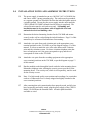
1
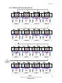
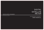
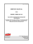
350-300R-ISSUE4.0 121010
SERVICE MANUAL
FOR
MODEL 350-300R
VISITATION POWER SYSTEM
EQUIPPED WITH FILTERED RECORDING CONNECTIONS
Serving the Telephone Industry Since 1930
Communication Equipment
& Engineering Company
519 West South Park Street
Okeechobee, Florida 34972
Voice: 863-357-0798
Fax: 863-357-0006
ISSUE 4.0
IMPORTANT INFORMATION
FOR
CUSTOMER
Please fill in before you continue.
The following information is necessary when calling CEECO for assistance.
MODEL NUMBER
MODEL 350-300R VISITATION
POWEWR SYSTEM.
SERIAL NUMBER
DATE MANUFACTURED
LOCATION INSTALLED
For us to better serve you, please have this information available when calling for
technical support.
CEECO
Communication Equipment & Engineering Company
519 West South Park Street
Okeechobee, Florida 34972
(863) 357-0798 Voice
(863) 357-0006 Fax
CEECO
Communication Equipment & Engineering Company
PROPRIETARY
2
ISSUE 4.0
TABLE OF CONTENTS
SECTION
PAGE
1.0
INTRODUCTION................................................................................................... 4
2.0
GENERAL DESCRIPTION .................................................................................. 4
3.0
OPERATION .......................................................................................................... 4
4.0
RECOMMENDED TOOLS AND TEST EQUIPMENT .................................... 5
5.0
INSTALLATION NOTES AND ASSEMBLY INSTRUCTIONS ..................... 6
6.0
TESTING................................................................................................................. 7
7.0
SPECIFICATIONS................................................................................................. 8
8.0
PARTS LIST ........................................................................................................... 9
9.0
REPAIR AND RETURN INFORMATION....................................................... 10
10.0 WARRANTY POLICY ........................................................................................ 11
CEECO
Communication Equipment & Engineering Company
PROPRIETARY
3
ISSUE 4.0
1.0
INTRODUCTION
The practices in this manual provide installation, technical and maintenance
information for Model 350-300R Visitation Power System.
The information in this manual is subject to change without notification.
For information not included in this manual, please call or write:
CEECO
Customer Service
519 West South Park Street
Okeechobee, Florida 34972
(863) 357-0798
(863) 357-0006 FAX
2.0
GENERAL DESCRIPTION
The CEECO Model 350-300R is a Visitation Power System designed for special
purpose applications that require a rugged and convenient means for wiring
multiple visitation units to the power supply, individual loops, and recording
apparatus. The system includes an AC to DC power supply, insulated screw
terminals for up to 32 visitation units (16 pair), insulated screw terminals for
attaching recording apparatus to each pair, audio balancing and filtering
components, and instruction plate, all in a rack or wall mountable, pre-wired
configuration with mounting hardware.
Note: Wire for connecting the 350-300R to the telephone/visitation units and/or
the recording apparatus is not included.
3.0
OPERATION
The CEECO Model 350-300R Visitation Power System is designed to provide
power, talk path loops, and recording points for up to 16 pairs (32 units) of the
CEECO 350 Series Visitation Telephone Units. Once installed, the system
provides regulated and balanced power such that each telephone pair may conduct
a conversation of high sound quality immediately upon lifting each pair to the ear.
The record connection points provide capacitance filtering for clear quality sound
recordings from each pair. The record parameters are dependent upon the chosen
apparatus.
CEECO
Communication Equipment & Engineering Company
PROPRIETARY
4
ISSUE 4.0
4.0
RECOMMENDED TOOLS AND TEST EQUIPMENT
Volt/Ohm Meter
¼” Nut Driver
Flat Blade Screw Driver
Small Flat Blade Screw Driver
Wire Strippers/Cutters 22-26 gauge
Small Needle Nose Pliers
Security Tool, CEECO Part Number 301-064.
***** WARNING *****
A.
Never install telephone wiring during a lightning
storm.
B.
Never install telephone wiring in wet locations unless the
wiring is specifically designed for wet locations.
C.
Never touch uninsulated telephone wires or terminals unless
the telephone line has been disconnected at the network
interface or other power supply.
D.
Use caution when installing or modifying telephone lines or
attached equipment.
E.
Do not attach wiring to or remove wiring from the CEECO
Model 350-300R without first unplugging the unit from the
AC power source.
CEECO
Communication Equipment & Engineering Company
PROPRIETARY
5
ISSUE 4.0
5.0
INSTALLATION NOTES AND ASSEMBLY INSTRUCTIONS
5.1
The power supply is intended to run on a 100-240 VAC 2A 50/60Hz line
and comes with a 3-prong grounding plug. The outlet must be grounded,
or a separate ground wire should be run from the individual phone units to
a suitable ground. Do not plug the power supply into the outlet until the
CEECO Model 350-300R is mounted and all wiring is completed. The
selected location must be safe and secure and, *Grounding and
installation must be in accordance with all applicable local and
national electrical and building codes.
5.2
Determine the desired mounting location for the 350-300R and mount
securely to the wall or rack utilizing the include hardware. Page 12 of this
manual may be referenced for dimensions for mounting.
5.3
Attach the wire pairs from each visitation pair to the appropriate screw
terminal positions on the 350-300R, as per the diagram on page 13 of this
manual. It is best to match the wire color codes between the visitation
units and the visitation system. For those visitation telephone units that
have red and green wires, the green corresponds to gray and the red
corresponds to white on the 350-300R.
5.4
Attach the wire pairs from the recording equipment to the appropriate
screw terminal positions on the 350-300R, as per the diagram on page 13
of this manual.
5.5
Run the modular cords through the knock out holes in the mounting boxes.
Mount the telephone units, utilizing the security screws provided, to the
mounting boxes. The security tool, which is sold separately, must be used
for the security screws.
5.6
Note: For high sound quality conversations and recordings, be certain that
each set of connected wires is cleanly stripped and tightly attached to the
screw terminal positions.
5.7
After ensuring that each connection has been properly made, and all wires
have been neatly and safely routed, plug the power supply of the CEECO
Model 350-300R into the intended outlet. All audio paths should be
available as wired.
CEECO
Communication Equipment & Engineering Company
PROPRIETARY
6
ISSUE 4.0
6.0
TESTING
6.1
Once installation has been completed, allow the phones to rest on-hook a
few minutes, with the power supply on.
6.2
Lift the handsets of the units that are intended to talk to one another.
Determine that normal conversation is allowed. If so, return the handsets
to the cradles. The phone units are ready for use.
6.3
If normal conversation does not take place, please review the installation
steps. Make a visual check to ensure that all wires and connectors are as
they should be. Remember that the phone units, which are connected to
the same screw terminal points, will allow talk paths to one another. A
phone connected to one screw terminal point cannot talk to a phone
connected to another jack/interface.
6.4
Conduct a test recording from each of the telephone pairs to ensure that
the recording operation is clear and as intended. If the recording is not
clear or as intended, re-examine the wiring to the record points of the 350300R. Remember that each of the recording wire pairs can only record
voice from the telephone units that are wired to that same screw terminal
set on the 350-300R.
6.5
Once it has been determined that the installation and connections are
correct, the system is ready for use. If trouble is still experienced, please
refer to section 9.2 of this manual.
CEECO
Communication Equipment & Engineering Company
PROPRIETARY
7
ISSUE 4.0
7.0
SPECIFICATIONS
INPUT POWER:
100-240VAC, 2A, 50/60Hz
OUTPUT POWER:
15VDC, 4A
LOOP CURRENT:
23 ma min. to 80 ma max.
IMPEDANCE:
600 Ohms
LOOP RESISTANCE:
100 Ohms 2 Watt
ENVIRONMENTAL:
Temperature 0° C to 50° C
Humidity
20%-90% non-condensating
RECORD CAPACITANCE: 4.7 uF 35V
WIRE GAUGE:
24 Gauge (White=Low; Gray=High)
DIMENSIONS:
19" Wide x 10.5" High x 3" Deep
MOUNTING:
RACK 19” Wide x 7.5” High
WALL 16” Wide x 9 3/16” High
WEIGHT:
Approximately 4 lb.
CEECO
Communication Equipment & Engineering Company
PROPRIETARY
8
ISSUE 4.0
8.0
PARTS LIST
QUANTITY PART NUMBER
DESCRIPTION
1
350-300R
Visitation Power System
1
350-255
Power Supply
8
301-10086
8 Position Insulated Screw Terminal
1
301-030
Instruction Frame
32
301-5160
100 Ohm 2 Watt Resistor
16
301-1009
4.7 uF 35V Capacitor
4
Hardware
#10-32 x 1" Screw, Nut, Washer
4
Hardware
1.5” Deck/Dry Wall Screw
16
Hardware
6-32 x 1.5” Security Screw
3
Hardware
6-32 x .75” Security Screw
19
Hardware
6-32 Nut
2
Hardware
#6 Lock Washer
1
Hardware
#6 Flat Washer
CEECO
Communication Equipment & Engineering Company
PROPRIETARY
9
ISSUE 4.0
9.0
REPAIR AND RETURN INFORMATION
9.1
WARRANTY REPAIR
Any device returned requiring warranty service; repair or credit must be
accompanied with a "Return Material Authorization" (RMA) Form. It
must include: return-shipping instructions, original purchase order
number and special marking instruction. A description of the trouble
observed must be attached to the defective unit. This information must be
inside the shipping container.
9.2
DIRECT ALL INQUIRES TO:
CEECO
Repair Department
519 West South Park Street
Okeechobee, Florida 34972
9.3
NON-WARRANTY REPAIR
CEECO will repair equipment out of warranty for a set charge plus parts.
The customer must pay the shipping costs both directions.
9.4
RETURN FOR CREDIT
Material may be returned for credit only with prior approval. Material
authorized for return is subject to a 20% restocking charge based on the
manufacturer's list price. Return RMA must be requested no later than 30
days after original shipment.
CEECO
Communication Equipment & Engineering Company
PROPRIETARY
10
ISSUE 4.0
10.0 WARRANTY POLICY
10.1
GENERAL
CEECO products are guaranteed to be free of defects in material and
workmanship for a period of 365 days from the date of original purchase.
CEECO's obligation under this warranty is limited to repair or
replacement of any part found to be defective by CEECO. Under no
circumstances shall CEECO be liable for loss, damage, cost of repair or
consequential damages of any kind, which have been caused by neglect,
abuse, acts of God or improper operation of equipment. This warranty is
limited to the value of material only.
10.2
PRINTED CIRCUIT BOARDS
Printed circuit boards should not be field repaired. If a unit is found to be
faulty, replace it with another unit and return the faulty unit to CEECO for
repair. Modifications by any one other than CEECO will void the
warranty.
CEECO
Communication Equipment & Engineering Company
PROPRIETARY
11
ISSUE 4.0
11.0 DIMENSION & WIRING DIAGRAM
CEECO
Communication Equipment & Engineering Company
PROPRIETARY
12
ISSUE 4.0
12.0 WIRING DETAILS DIAGRAM
REC
OUT
PAIR 13
REC
OUT
PAIR 9
REC
OUT
PAIR 14
REC
OUT
PAIR 10
REC
OUT
PAIR 15
REC
OUT
PAIR 11
REC
OUT
PAIR 16
REC
OUT
PAIR 12
REC
OUT
REC
OUT
REC
OUT
REC
OUT
PAIR 5
PAIR 6
PAIR 7
PAIR 8
REC
OUT
REC
OUT
REC
OUT
REC
OUT
PAIR 1
PAIR 2
PAIR 3
PAIR 4
TO
POWER
SUPPLY
CEECO
Communication Equipment & Engineering Company
PROPRIETARY
13