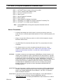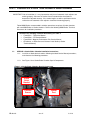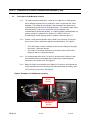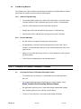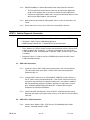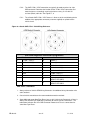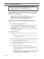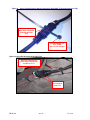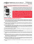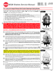
1
e•STROKE® e.S3 / GEN 3 Installation Guide
®
The e-STROKE e.S3 / GEN 3 System is designed to continuously monitor S-Cam Drum Type
braking systems while in operation and during stationary brake inspections. The e-Stroke e.S3 /
GEN 3 system also includes various diagnostic capabilities as described in this guide.
•
Reference Service Bulletin EB 08-001 for additional system information and
specifications.
e-Stroke systems utilize piston rod travel measurements from the brake chambers as well as
brake application pressure and vehicle speed to determine the status of the brake system. In
addition the e-Stroke e.S3 / GEN 3 system will also monitor lining wear if installed. e-Stroke brake
chambers are the same as MGM Brakes standard chambers but with the addition of a piston rod
magnet, and sensor receptacle which accepts the e-Stroke sensor. At the center of the e-Stroke
system is the Chassis Communication Module or CCM, which accepts all of the systems inputs
and outputs and uses software to monitor the vehicles braking system.
•
Reference MGM Drawing (P/N 9230100) for a complete e-Stroke e.S3 system schematic
and wiring diagram.
This Service Bulletin is intended to provide instruction on installing an e-Stroke e.S3 / GEN
3 system. The steps listed below outline the installation of each system component. In
addition, the e-Stroke Technical Manual includes Technical Documents which provide
supporting information for each installation step.
•
The e-Stroke Technical Manual is available on CD (P/N 8090091) or for download at
www.MGMBrakes.com.
How to Use this Installation Guide:
•
This Service Bulletin is broken up into steps covering an overview of the
installation for each system component.
•
Review all referenced Technical Documents for additional information pertaining
to each step.
®
MGM Brakes e•STROKE Technical Support:
1-877-4-e-STROKE
www.mgmbrakes.com
EB 08-003
rev. 02
1 of 16
e•STROKE® e.S3 System Components & Installation Steps:
®
STEP 1:
STEP 2:
STEP 3:
STEP 4:
STEP 5:
STEP 6:
STEP 7:
STEP 8:
STEP 9:
e•STROKE Brake Chambers & Sensor Assemblies
Chassis Communications Module (CCM)
Pressure Transducer & Harness
Power Harness
Vehicle Diagnostic Connection
Warning Light(s)
Sensor Harnesses (Routing & Installation)
®
e•STROKE e.S3 / GEN 3 Post System Installation Functionality Test
®
e•STROKE e.S3 / GEN 3 System Diagnostics
Note:
Contact MGM Brakes for lining wear component installation technical
information.
Notes & Precautions:
•
If drilling a hole through the vehicle’s body is necessary to route any harnesses,
make sure to use a weather-proof rubber grommet or silicone sealant to properly seal
the hole.
•
Always use care when drilling any surface as vehicle critical components may be
behind the drilled surface.
•
Use ONLY Black UV (ultraviolet) Resistant Cable Ties (or equivalent) for harness
installation.
•
All e-Stroke harnesses are to be secured to existing wire harnesses, frame
components, and/or airlines every 12-18”. Make sure all connections are NOT
unduly stressed and each connector is secured with a cable tie through the
connector clip.
WARNING:
Installation, maintenance and replacement of MGM Brakes e-Stroke chambers and
related system components require a high degree of skill and experience. Improper
installation, maintenance or replacement can result in brake failure and resulting loss
of control of the vehicle and possible injury or death. MGM Brakes, a division of
Indian Head Industries, Inc. (IHI), does not authorize anyone other than highly skilled
and experienced persons to attempt to utilize the instructions contained in this
Installation Manual. MGM Brakes and IHI shall have no liability of any kind for
damages arising out of any other use of the information contained within this
Installation Manual.
IMPORTANT: Be aware that proper installation and warranty coverage of e-Stroke equipped brake
chambers require that several important, unique steps be taken in addition to those
found in the standard MGM Brakes Service Manuals. See STEP 1 for Special eStroke Installation Instructions.
IMPORTANT: If you need a Technical Document or Service Manual, it can be downloaded or a
‘hard copy’ can be requested by visiting the MGM Brakes website
(www.mgmbrakes.com), or contact your MGM Brakes representative for assistance.
EB 08-003
rev. 02
2 of 16
®
STEP 1: Installation of e•STROKE Brake Chambers & Sensor Assemblies
IMPORTANT: Prior to installation, it is very important to verify that all automatic slack adjusters are
working properly. Measure the stroke of each actuator before installation to
determine if adjusted correctly. If the stroke lengths are within specification for the
vehicle then the automatic slack adjusters should be functioning properly.
Follow MGM Brakes recommended installation procedures to replace all brake chambers
with new MGM Brakes e-Stroke chambers. Refer to the following MGM Brakes Technical
Documents for installation procedures:
Reference the following Technical Document(s) for STEP 1:
• Form #5011 - TR Service Manual
• Form #5042 - LTR Service Manual
• Form #5044 - Magnum Performance Plus Service Manual
• EB 08-006 – e-Stroke Sensor & Harness Install Guide (e-Stroke
Technical Manual)
1.1:
SPECIAL e-Stroke Brake Chamber Installation Instructions:
1.1.1:
Install the e-Stroke brake chambers following standard Service Manual procedures,
and reference the following procedures.
1.1.2:
See Figure 1 for e-Stroke Brake Chamber Special Components.
Figure 1: e-Stroke Brake Chamber Special Components
Strain
Relief
Bracket
e-Stroke
Sensor
EB 08-003
Sensor
Port
rev. 02
3 of 16
1.1.3:
It is important to properly orientate the e-Stroke brake chambers. Mount the brake
chamber so the ‘Sensor Port’ is on the side closest to centerline of vehicle (Inboard).
Be aware that there are right and left hand actuators. See Figure 2.
1.1.4:
All e-Stroke brake chamber assemblies include a strain relief bracket (P/N 8090039).
This strain relief bracket is intended to secure the sensor harness after insertion into
the chamber sensor port.
Position the Strain Relief Bracket on the top mounting bolt (with bracket facing inward
toward centerline of vehicle) before tightening nut. Move the strain relief bracket as
required if potential for interference with other vehicle components is possible. See
Figure 2.
Figure 2: e-Stroke Brake Chamber Orientation
Strain Relief
Bracket
Orientation
Inboard to
Sensor Orientation
Inboard towards
Centerline of
Vehicle
1.1.5:
1.2:
Complete Brake Chamber Installation and connect air-lines.
e-Stroke Sensor Installation
1.2.1:
Remove the dust plug (Gray Plastic) from the Sensor Port on the bottom of brake
chamber.
1.2.2:
Firmly grip the e-Stroke Sensor (P/N 8290120) by the lower ‘ears’ with thumb and
forefinger. Then insert into Sensor Port by pushing straight in until it seats against
receptacle. See Figures 3, 4.
WARNING: Be very careful when installing Sensor Assembly! Grip by lower ‘ears’
and PUSH STRAIGHT INTO RECEPTACLE ONLY; DO NOT PUSH AT
AN ANGLE or damage may occur, thereby voiding the Sensor
Assembly’s warranty. After installation, ensure adequate slack is present
in Sensor Assembly cable to allow for push-rod movement.
EB 08-003
rev. 02
4 of 16
Figure 3: e-Stroke Sensor Installation – Appropriate Force Direction
Proper
Force
Improper
Force
Figure 4: e-Stroke Sensor Installation
Correct
EB 08-003
Incorrect
1.2.3:
Secure the Sensor Harness to Strain Relief Bracket using UV resistant (Black) cable
ties leaving some slack in between the Sensor Port and the Strain Relief Bracket.
1.2.4:
Route the Sensor Harness along the air-line securing every 12-18” with UV resistant
(Black) cable ties.
1.2.5:
Reference EB 08-006 for Additional Sensor & Harness Installation Information.
rev. 02
5 of 16
STEP 2: Installation of Chassis Communications Module (CCM)
2.1:
Choosing the CCM Mounting Location
2.1.1:
The CCM must be mounted within 1 meter of the J1939 access. SAE specifies
that J1939 drop leg extensions are limited to 1 meter in length from the J1939
backbone. The location of the available J1939 connections will determine the
CCM mounting location for most retrofit applications. The communications closet
behind the driver’s seat (for bus applications where equipped) is the
recommended CCM mounting location, as J1939 and ignition switched power are
typically available. In addition, the e-Stroke e.S3 / GEN 3 CCM is not
environmentally sealed requiring interior installation. Reference Step 4, 5.
2.1.2:
Choose a CCM mounting location which provides accessibility for Technicians.
Access to the CCM is required for diagnostic troubleshooting. See Figure 5.
•
•
The CCM includes a Red Push Button on the face for initiating warning light
blink codes. Reference Step 9.3.
The CCM “P2” connector needs to be accessible to connect the RS-232
Diagnostic Harness. Reference Step 9.1.
2.1.3:
It is recommended that at least 2” of space is left around the CCM on all sides.
Care should be taken to avoid exposure to anything that could damage the
connectors or the module itself. See Figure 5.
2.1.4:
Mount the CCM in an orientation which allows the Technicians and Operators to
clearly read the text on the front of the CCM (Not upside down or sideways from
the Technicians perspective). See Figure 5.
Figure 5: Examples of CCM Mounting Locations
CCM Push
Button
Access
CCM P2 Diagnostic
Connector
Access
EB 08-003
rev. 02
6 of 16
2.2:
CCM Mounting Methods
The e-Stroke e.S3 / GEN 3 CCM may be mounted using either the provided adhesive tape on
the back of the CCM or (2) fasteners with the mounting tabs.
2.2.1:
2.2.2:
Adhesive Tape Mounting
•
The included adhesive tape on the back of the CCM requires a clean flat surface
for proper adhesion. Either a painted or gloss plastic surface is recommended.
•
Clean the CCM mounting surface to remove dirt and grease.
•
Remove the red film from the adhesive tape and press CCM into place.
•
Verify that the CCM is adhered to the mounting surface after installation.
Fastener Mounting
•
Use the CCM as a template for locating the mounting holes.
•
Drill appropriately sized holes for the mounting fasteners to be used. Two ¼”
fasteners are recommended. Locking nuts are recommended for machine screw
type fasteners.
•
Always use care when drilling any surface as critical components may be behind
the drilled surface.
•
Install CCM using mounting tabs and selected fasteners.
STEP 3: Installation of Pressure Transducer & Harness
3.1:
EB 08-003
Choosing the Pressure Transducer Mounting Location
•
The e-Stroke pressure transducer is intended to measure brake application
pressure.
•
The recommended mounting location for the pressure transducer is at the
Brake Treadle Valve Secondary Delivery Output.
•
Bus applications typically have a Treadle Valve Output manifold with multiple
ports containing other pressure switches and transducers.
•
Tractors & Trucks may have a spare port on the treadle valve body.
rev. 02
7 of 16
3.2: Pressure Transducer Mounting
3.1.1:
The e-Stroke pressure transducer includes a ¼” npt male fitting. Either locate a
spare ¼” npt port in the brake treadle valve secondary delivery output or add one
using standard ¼” npt brass fittings. See Figure 6.
3.1.2:
Install the pressure transducer into the air-port using a thread sealer. Verify the
connection to be leak free after installation.
Figure 6: Pressure Transducer Mounted to Brake Treadle Valve
Brake
Treadle
Valve
Pressure
Transducer
3.3: Pressure Transducer Harness Installation
EB 08-003
3.3.1:
Apply a label marked “P” on both ends of the pressure transducer harness if
harness is not already labeled.
3.3.2:
Connect the pressure transducer harness to the pressure transducer. Note the
harness orientation as the CCM and Pressure Transducer use different
connectors.
3.3.3:
Route the pressure transducer harness to the CCM and connect to the “P8”
connector. Secure the harness to the transducer body and every 12-18” along
the harness using UV resistant (Black) cable ties.
rev. 02
8 of 16
STEP 4: Power Harness Installation
Reference the following e-Stroke Technical Manual Document(s) for STEP 4:
• EB 08-006 – e-Stroke Sensor & Harness Install Guide
• MGM Drawing P/N 9230100 – e-Stroke GEN 3 System Schematic
•
The e-Stroke e.S3 / GEN 3 system requires that ignition switched power, ground and
J1708 or J1939 circuits are connected to the CCM.
•
Use only MGM Brakes e-Stroke e.S3 / GEN 3 Power Cables for power connection.
•
Reference Figure 7 (Below) for CCM Power, Diagnostic & Alarm Connections.
Figure 7: e.S3 / GEN 3 CCM Power, Diagnostic, Alarm Connections
(MGM P/Ns 8791xxx)
CCM
Connector
Terminal
Function
P1
P1
1
2
P1
P1
P1
P1
P1
P1
4
5
6
7
9
10
SAE J1708 / 1587+
SAE J1708 / 1587 System Power +
12 / 24V DC Ignition Switched
System Ground Alarm 1 +
Alarm 2 +
Alarm 1 Alarm 2 -
P3
1
SAE J1939 CAN HI
P3
2
SAE J1939 Shield
P3
P15
P15
P15
3
2
3
4
SAE J1939 CAN LO
Alarm 3, 4 Alarm 3 +
Alarm 4 +
Aftermarket
Harness P/N
Harness Wire
Color
8290189
8290189
Blue
White
8290233
8290233
8290233
8290233
8290233
8290233
8290218,
8290257
8290218,
8290257
8290218,
8290257
8290235
8290235
8290235
Red
Black
Dark Blue
Light Blue
White
Gray
Yellow
NA
Light Green
White
Tan
Pink
4.1: Power Connections
4.1.1:
EB 08-003
Connect the supplied Power Cable (P/N 8290233) to the CCM “P1” connector
and route to power / ground connection location.
•
The typical source for electrical power is the vehicle’s 12 VDC or 24 VDC
(ignition-switch) Auxiliary Circuit with 5 Amp capacity.
•
This connection can typically be made at the vehicle’s ‘Power Distribution
Panel’ (PDP) or fuse box.
•
Consult the vehicle OEM wiring diagram to determine the appropriate
connection locations.
rev. 02
9 of 16
4.1.2:
MGM P/N 8290233: e-Stroke Aftermarket Power Cable Special Instructions
• The Red and Black Power Wires & Loom may be trimmed to appropriate
length. Leave enough slack in the harness to allow for minor adjustment.
• Connect the supplied fuse holder with 5 amp fuse to the Power Harness Red
Wire using included solder & seal connector.
4.1.3:
Make electrical connection to vehicle power source. Insure all connections are
sound.
4.1.4:
Secure the harness every 12-18” with UV resistant (Black) cable ties.
STEP 5: Vehicle Diagnostic Connection
Reference the following e-Stroke Technical Manual Document(s) for STEP 5:
• EB 08-007 – SAE J1708 & J1939 Wiring Reference
• MGM Drawing P/N 9230100 – e-Stroke GEN 3 System Schematic
•
The e-Stroke e.S3 / GEN 3 systems must be connected to the vehicles J1939 circuit
in order to operate with all features. If J1939 is not available on the vehicle then
J1708 should be used. Connecting both J1939 and J1708 is not necessary if J1939
is available.
•
Reference Figures 7, 8 and the vehicles OEM Wiring schematic for SAE J1939 /
J1708 connection locations.
5.1: SAE J1939 Connection
5.1.1:
Locate or install an SAE J1939 Drop Leg connection in the circuit back bone.
This connection needs to be within 1 meter of the CCM mounting location.
Reference Step 2.1.
5.1.2:
e-Stroke SAE J1939 harnesses (P/N 8290218, 8290257) include a Deutsch 3Pin DT Series industry standard connector. If the vehicle J1939 circuit will not
accept this connector then the supplied J1939 harness can either be modified
with the appropriate connector (customer supplied) or a new harness may be
built. Reference MGM Drawing P/N 9230100 – e-Stroke GEN 3 System
Schematic for Connector Information.
5.1.3:
Connect the SAE J1939 Harness to the CCM “P3” Connector and the Vehicle
Drop Leg connection securing the harness every 12-18” with UV resistant (Black)
cable ties.
5.2: SAE J1708 / J1587 Connection
5.2.3:
EB 08-003
Connect the e-Stroke J1708 / J1587 harness (P/N 8290189) to the Power
Harness connector marked “J1708”.
rev. 02
10 of 16
5.2.2:
The SAE J1708 / J1587 connection can typically be made near the 6 or 9 pin
OBD connector. Determine the location for the J1708 / J1587 connection and
route the harness accordingly securing the harness every 12-18” with UV
resistant (Black) cable ties. See Figures 7, 8.
5.2.1:
The e-Stroke SAE J1708 / J1587 harness is blunt cut at the end allowing for the
addition of the appropriate connector (customer supplied) or spliced into the
vehicle circuit.
Figure 8: e-Stroke SAE J1708 / J1939 Wiring Reference
SAE OBD Diagnostic Connector Designations
6-Pin Connector
9-Pin Connector
A
J1708 / J1587(+)
A
Power (-)
B
J1708 / J1587(-)
B
Power (+)
C
Power (+)
C
CAN J1939 HI (+)
D
N/A
D
CAN J1939 LO (-)
E
Power (-)
E
CAN J1939 Shield
F
N/A
F
J1708 / J1587 (+)
G
J1708 / J1587 (-)
CAN J1939 HI (+) CHASSIS
NEW FLYER ONLY
CAN J1939 LO (-)CHASSIS
NEW FLYER ONLY
H
J
SAE J1939 / J1708 Notes:
1. Always reference Vehicle OEM Wiring Schematics for additional wiring information: wire
color, locations.
2. Consult vehicle manufacturer for recommended connection methods.
3. Some 2009 and newer New Flyer Buses have a split J1939 circuit, Powertrain & Chassis.
Always consult New Flyer OEM wiring schematic for vehicle specific connections. The
table above indicates the 9-Pin OBD connector Powertrain & Chassis connections for
some New Flyer Buses.
EB 08-003
rev. 02
11 of 16
STEP 6: Warning Light(s) Installation
Reference the following e-Stroke Technical Manual Document(s) for STEP 6:
• EB 08-006 – e-Stroke Sensor & Harness Install Guide
• MGM Drawing P/N 9230100 – e-Stroke GEN 3 System Schematic
The e-Stroke e.S3 / GEN 3 System will monitor the brake status and display faults through
dash mounted warning light(s). The e-Stroke e.S3 / GEN 3 system has (4) warning light or
alarm outputs as listed below. All applicable warning lights will need to be accounted for
when determining the mounting location.
•
•
•
•
Alarm 1: Tractor / Truck / Bus Brake Monitor Warning
Alarm 2: Tractor / Truck / Bus Lining Warning (Lining Wear Applications Only)
Alarm 3: Trailer Brake Monitor Warning (Tractor Applications Only)
Alarm 4: Trailer Lining Warning (Tractor Applications Only)
The e-Stroke Warning Light Kit(s) (P/Ns 9090105, 9090106) include an amber ½ inch
diameter panel mount lamp. Each kit includes appropriate labels for all warning light
functions.
6.1: Choose the Waning Light(s) Mounting Location
•
•
•
It is recommended that the warning light(s) be mounted near the park brake release
valve. As this will help associate the lamp warning with the vehicle brakes.
The warning light(s) harnesses must be long enough to reach the CCM from the
mounting location.
Insure that the mounting location allows for enough room to apply the warning light
label(s) next to the warning light(s).
6.2: Warning Light Installation
6.2.1:
Drill a ½ inch diameter hole in the designated panel for each warning light to be
installed.
Note:
EB 08-003
Always use care when drilling any surface as critical components may be
behind the drilled surface.
6.2.2:
Pull the warning light cable through the hole and push the lamp to lock into place.
6.2.3:
Clean the warning light mounting surface removing dirt and grease. Apply the
appropriate warning light label next to the lamp.
6.2.4:
Route the warning light harnesses to the CCM securing harness every 12-18”
with UV resistant (Black) cable ties.
6.2.5:
Connect the warning light harnesses to the CCM as follows:
•
Alarms 1 & 2: Connect the Warning Light Harness to the appropriately
labeled leads on the CCM power harness (P/N 8290233) which is connected
to the CCM “P1” Connector.
•
Alarms 3 & 4: Connect the Warning Light Harness to the appropriate labeled
Warning Light Adapter Harness (P/N 8290235) lead which is connected to
CCM P15 Connector. (Tractor Applications Only)
rev. 02
12 of 16
STEP 7: Sensor Harnesses (Routing & Installation)
Reference the following e-Stroke Technical Manual Document(s) for STEP 7:
• EB 08-006 – e-Stroke Sensor & Harness Install Guide
• MGM Drawing P/N 9230100 – e-Stroke GEN 3 System Schematic
IMPORTANT: Using proper harness installation practices is the most important
action which can be taken to insure the long term durability of the eStroke system. Reference Service Bulletin EB 08-006 for additional
system information and specifications.
7.1:
Label both ends of each Sensor Harness for ease of Identification at CCM and
Sensor.
Note:
EB 08-003
Care should be taken to ensure that connections on the wheel ends will
match designations on the CCM, otherwise when a fault is displayed it may
not match the reading because of switched cable ends.
7.2:
Connect the required length Sensor Harness to each Sensor located near the brake
chambers. Note the harness orientation as that the Sensor and CCM use different
connectors.
7.3:
Route each Harness from the Sensor to the CCM. See Figure 9.
• It is recommended that the e-Stroke harnesses are routed along with the vehicles
existing wire harness as much as possible.
• Route harnesses along air lines from the actuator to the vehicle frame. The
vehicle OEM designed and routed these air lines to account for suspension
movement and steering articulation.
• Secure connectors together by routing a UV resistant (Black) cable tie through
the connector clip. This will insure the connectors are completely locked
together. See Figure 9.
• Secure the connectors to an air line, cable harness bundles, or frame
components using UV resistant (Black) cable ties around connector body. See
Figure 10.
• Connectors must not be stressed or bent when secured.
• Connectors must be located in a serviceable location.
• Secure 6-8” of slack harness near the connectors for future service.
7.4:
Secure the Sensor Harnesses every 12-18” using UV resistant (Black) cable ties.
7.5:
Connect Sensor Harnesses to appropriate CCM connector for each wheel end.
rev. 02
13 of 16
Figure 9:
Secure e-Stroke Sensor Harness Connector with Cable Tie through Connector Clip
Packard / Delphi
Metri-Pack 150 Series
Sealed Connector
Clip
Standard Cable Tie:
0.18” Width
50lb Tensile Strength
Figure 10: Securing Harnesses with Cable Ties
Harnesses Secured on
either side of Connector
and Every 12-18”
Connectors
Secured with
Cable Ties
EB 08-003
rev. 02
14 of 16
®
STEP 8: e•STROKE e.S3 / GEN 3 Post System Installation Functionality Test
Reference the following e-Stroke Technical Manual Document(s) for STEP 8:
• EB 09-004 - e-Stroke Inspection Checklist
• EB 08-008 – e-Stroke GEN 3 Post Install Functionality Test
• EB 08-016 – e-Stroke GEN 3 Truck / Bus Troubleshooting Guide
The Installation is now complete.
The following procedure is intended to test the e-Stroke system functionality after installation.
Following these steps will verify that the system is installed correctly and the vehicles
foundation brakes are operating within the recommended limits.
8.1:
Required Vehicle Status: In order to complete this test, the following systems must
be completely operational on the vehicle:
• Air brake system
• Foundation Brake System
• Engine Controller
• Electrical Ignition System which powers the e-Stroke System
• SAE J1708 / J1939 circuits (where applicable)
• Vehicle Warning Light I/O System (where applicable)
8.2:
Test Preparation
• Chock vehicle wheels.
• Build air system pressure to 100-110psi using either the engine compressor or
external compressed air supply.
8.3:
Reference Technical Document EB 09-004 – e-Stroke Inspection
Check List for Inspection Outline.
8.4:
Reference Technical Document EB 08-008 – e-Stroke GEN 3 Post
Install Functionality Test for complete functionality test
Instructions.
8.5:
Reference Technical Document EB 08-009 – e-Stroke GEN 3 Truck
/ Bus Troubleshooting Guide for additional technical information.
®
MGM Brakes e•STROKE Technical Support:
1-877-4-e-STROKE
www.mgmbrakes.com
EB 08-003
rev. 02
15 of 16
STEP 9: e•STROKE® e.S3 / GEN 3 System Diagnostics
9.1:
RS-232 Computer Diagnostic Program: MGM Kit P/N 9090109
Reference the following e-Stroke Technical Manual Document(s) for STEP 9.1:
• EB 08-012 – e-Stroke GEN 3 RS-232 Program Users Guide
The e-Stroke RS-232 Diagnostic Kit (P/N 9090109) software program will operate with a Lap
Top Computer (customer supplied) the diagnostic harness. This tool may be used to acquire
the following information from the e-Stroke e.S3 / GEN 3 CCM:
•
•
•
•
9.2:
Current Wheel Specific Brake & Lining Status
Stored Fault History
System Status
CCM Information: Software Version, Configuration, Serial Number.
e-DT - e-Stroke Diagnostic Tool: MGM Kit P/N 9090110
Reference the following e-Stroke Technical Manual Document(s) for STEP 9.2:
• EB 08-013 – e-DT Diagnostic Tool Users Guide
9.3:
•
The e-stroke e-DT is a hand held diagnostic tool that is designed to work with MGM
Brakes e-Stroke systems. The e-DT monitors the vehicles CAN network for the e-stroke
system status and brake faults codes.
•
The e-DT Diagnostic Kit (P/N 9090110) contains all harnesses and equipment required to
use the diagnostic tool.
•
The e-DT can be easily used by connecting the harness to either a 6 or 9 pin diagnostic
port. The e-DT will automatically turn on and link up with the e-Stroke system when
connected.
•
The e-DT displays real time e-Stroke system status and active brake faults. In addition
the brake fault history can be acquired from e-Stroke e.S3 / GEN 3 systems. Vehicle
speed and brake application pressure are also displayed on the e-DT for diagnostic
purposes.
Warning Light Blink Codes
Reference the following e-Stroke Technical Manual Document(s) for STEP 9.3:
• EB 08-011 – e-Stroke GEN 3 Blink Code Operation Guide
EB 08-003
•
The e-Stroke system warning lamp(s) will illuminate when the system is operating and an
active fault is occurring. The nature of the fault will determine which lamp illuminates,
such as a lining fault will illuminate Alarm 2. The e-Stroke e.S3 / GEN 3 System will also
display diagnostic blink codes for active and inactive / stored faults through the warning
lights.
•
Press the Red Push Button on the CCM face for 1-2 seconds to initiate the blink code
sequence. Pressing the push button for 5 seconds will clear the CCM fault history.
rev. 02
16 of 16