1
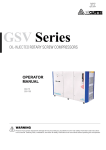
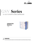
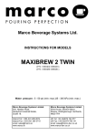
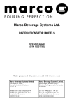
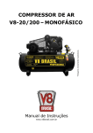
CAP320
AUGUST, 2004
REV.A
CURTIS – TOLEDO
OPERATOR’S MANUAL
SUPPLEMENT
AF Series Compressors VS models with VFD
WARNING
Personal injury and/or equipment damage will result by failing to pay attention
to the vital safety information and instructions in this manual.
Carefully read, understand, and retain all safety information and instructions
before operating this compressor.
Curtis – Toledo
1905 Kienlen Ave. St. Louis, MO 63133
phone: 314-383-1300 fax: 314-381-1439 Email: [email protected]
CAP320
FOREWORD
The Curtis-Toledo AF Series is a single stage helical rotary screw air compressor, belt or direct
driven by an electric motor. The package includes the compressor (air end), main and fan motors,
VFD controls for operating the motors, air intake system, air/oil separator and compressor
instrumentation.
Curtis-Toledo designs the AF Series compressors for indoor installation. Standard control panel
enclosure is NEMA 1.
This manual is a supplement to basic rotary screw manual and written to aid the user in the daily
operation of your compressor. It does not repeat installation, safety, and maintenance instruction
and have a target to give comprehensive description of control system functions and operation.
We urge you to read and follow these instructions for the safe and economical operation of this
unit.
Electricity and compressed air have the potential to cause severe personal injury and or property
damage. Before installing, wiring, starting, operating or making any adjustments identify the
components of the air compressor using basic manual and this supplement as a guide.
Qualified personnel, adequately equipped with the proper tools, should perform maintenance.
Follow the maintenance schedules as outlined in the manual to insure problem free operation
after initial start-up.
The operator should use common sense and good working practices while operating and
maintaining this unit.
i
CAP320
TABLE OF CONTENTS
1. CONTROL SYSTEM & SETTINGS..……………………………………………………………
1.1. INTRODUCTION ………………………………………………………………………………
1.2. SOFTWARE ……………………………………………………………………………………
1.3. PARAMETER TABLES. ………………………………………………………………………
1.3.1. BASIC PARAMETERS AND SETTINGS……………………………………………………
1.3.2. SERVICE AND STATISTICS…………………………………………………………………
1.3.3. ENERGY SAVINGS. ………………………………………………………………………….
1.3.4. COMPRESSOR TYPE DATA…………………………………………………………………
1.4. PARAMETER DEFINITIONS AND DESCRIPTIONS………………………………………
1.4.1. BASIC PARAMETERS………………………………………………………………………..
1.4.2. ENERGY SAVINGS……………………………………………………………………………
2. TOUCH SCREEN OVERVIEW & OPERATION……………………………………………….
3. DRIVE KEYPAD OPERATION…………………………………………………………………..
4. MAINTANENCE
5. DRAWINGS
1
2
2
2
3
3
3
4
4
5
5
6
7
25
27
28
CAP 320
1. CONTROL SYSTEM AND SETTINGS
1.1.Introduction
AF rotary screw compressor series with variable frequency AC drives (VFD) is a new generation of energy
saving Curtis compressors.
AF is compact package including: control panel with compressor & fan VFD, touch screen and other electrical
components; pressure and temperature sensors, air filter switch.
Compressor VFD - ACS800 AC drive (ABB Inc.) utilizes Direct Torque Control (TDC) of motor control system.
Fan VFD – ACS550 AC drive (ABB Inc.) utilize V/Hz control method.
Touch screen (TS) is Operator Interface Terminal connected to compressor drive PLC.
Detail drives information; safety & maintenance instructions are described in “ACS800 Hardware Manual”, ACS
Firmware Manual” & “ACS550 User’s Manual” included in document’s package of this unit.
1.2.Software
The ACS800 application consists of drive configuration parameter Groups and control. Software is custom
made for Curtis Toledo rotary screw compressors. VFD Parameter Groups used for drive PLC programming,
appear on drive keypad. Keypad must be used only ABB certified technical professionals.
Software provides the compressor operation in Pressure PI loop control. Compressor motor speed reflects the
system air demand at designed operating pressure.
2
CAP320
1.3. Parameter tables
1.3.1. Basic parameters and settings
Table 1
Parameter Name
Default
Min
External pressure
Sump pressure
Actual psi
Actual psi
0
0
200psi
200psi
Max
TS Fig.1, 7
TS Fig.1, 8
DP pressure
Calculated
0
15psi
N/A
Unload pressure
125psi
Load P
+10psi
Load pressure
105psi
85 psi
Operating pressure
(Load P+
Unload P)/2
Wake-up pressure
Load P
Shutdown pressure
Oil temperature
Shutdown
temperature
Auto restart time
Stop delay time
Blowdown time
Cutout delay time
Standby delay time
Control mode
140psi
Actual t°
Load P +
5psi
Load P –
20psi
0
32°F
225°F
0
30sec
5sec
10sec
0.5min
Auto
Shutdown
P-10psi
Unload P –
10psi
Unload P –
5psi
Display
Remarks
Displays actual pressure
Displays actual pressure
Calc. Sump P – Ext. P
Warning if DP >10psi
TS Fig.15
Default = Type 5 (Table 4)
TS Fig.15
Default = Type 5 (Table 4)
TS Fig.19
Default setting is calculated.
Compressor is in AUTO mode
Operating P
TS Fig.19
Default = Type 1-13 (Table 4)
215psi
225°F
TS Fig.45
TS Fig.1, 9
Default = Type 5 (Table 4)
Displays actual temperature
194°F
240°F
TS Fig.37, 45
Warning if t°=shutdn.t°- 10°F
240sec
240sec
120sec
100sec
60min
N/A
TS Fig.15
TS Fig.15
TS Fig.15
TS Fig.19
TS Fig.19
TS Fig.19
Motor max
speed
TS Fig.18
Manual=0, Auto=1-240 sec
Default = Type 1-13 (Table 4)
Default = Type 1-13 (Table 4)
Preset by program
Default = Type 1-13 (Table 4)
Auto, Constant
Must be set inside of max-min
motor speed range, if constant
mode applied
ON
TS Fig.18
5psi
TS Fig.18
Constant mode
motor speed
Motor min
speed
Remote control
OFF
0
10sec
5sec
10sec
0
N/A
Motor
min
speed
OFF
Lead/Lag control
0psi
0psi
Oil temperature
180°F
160°F
240°F
TS Fig.27
setpoint
PSI
BAR
PSI
TS Fig.20
Pressure unit
°F
°C
°F
TS Fig.20
Temperature unit
Notes: 1. Default setting, as an example for this manual, is type 5 (see Table 2).
2. Lead/Lag control disables Remote start/stop functionality.
3. Lead/Lag control installation, setup and recommended setting see 1.5.
Lead/Lag operational if
differential pressure
value has been set
Displays the setting
1.3.2. Service and statistics
Table 2
Parameter Name
Default
Min
1000 hrs
2000 hrs
4000 hrs
8000 hrs
2000 hrs
0 hrs
0 hrs
0 hrs
0 hrs
0 hrs
Running hours
0
0
99999
Loaded hours
0
0
99999
Oil filter
Air filter
Separator
Oil
Panel filter
Max
1000 hrs
2000 hrs
4000 hrs
12000 hrs
2000 hrs
3
Display
TS Fig.3-6
TS Fig.3-6
TS Fig.3-6
TS Fig.3-6
TS Fig.3-6
TS Fig.3-6,
22,37,45
TS Fig.3-6,
22,37,45
Remarks
Warning message at 0 hrs
Warning message at 0 hrs
Warning message at 0 hrs
Warning message at 0 hrs
Warning message at 0 hrs
CAP320
1.3.3. Energy savings
Table 3
Parameter Name
Energy savings
Dollar savings
Load motor Amp %
Unload motor Amp %
Motor load time %
Default
0
kWhx100
0.0
95%
30%
50%
Min
0 kWhX100
0.0
N/A
N/A
N/A
Max
99999
kWhX100
99999.9
150%
150%
100%
Display
Remarks
TS Fig.26
TS Fig.26
TS Fig.22
TS Fig.22
TS Fig.22
1.3.4. Compressor type data
Table 4
Parameter Name
Default
Min
Max
5sec
5sec
120sec
Blowdown time
30sec
10sec
240sec
Stop delay time
80psi / 5.5bar
60psi / 4.1bar
95psi / 6.6bar
Load pressure
100psi / 6.9bar
70psi / 4.8bar
105psi / 7.2bar
Unload pressure
115psi / 7.9bar
0
115psi / 7.9bar
Shutdown pressure
5sec
5sec
120sec
Blowdown time
30sec
10sec
240sec
Stop delay time
105psi / 7.2bar
85psi / 5.9bar
120psi / 8.3bar
Load pressure
125psi / 8.6bar
95psi / 6.6bar
130psi / 9.0bar
Unload pressure
140psi / 9.6bar
0
140psi / 9.6bar
Shutdown pressure
5sec
5sec
120sec
Blowdown time
30sec
10sec
240sec
Stop delay time
130psi / 9.0bar
110psi /7.6bar
145psi / 10.0bar
Load pressure
150psi /10.3bar 120psi / 8.3bar
155psi / 10.7bar
Unload pressure
165psi /11.4bar
0
165psi / 11.4bar
Shutdown pressure
5sec
5sec
120sec
Blowdown time
30sec
10sec
240sec
Stop delay time
155psi / 10.7bar 135psi /9.3bar
170psi / 11.7bar
Load pressure
175psi / 12.1bar 145psi /10.0bar
180psi / 12.4bar
Unload pressure
190psi / 13.1bar
0
190psi / 13.1bar
Shutdown pressure
Notes: 1. For pressure range 175 – 200psi consult factory.
2. Compressor type set by factory or field service personnel.
4
Comp type
1
1
1
1
1
5
5
5
5
5
9
9
9
9
9
13
13
13
13
13
CAP320
1.4. Parameter definitions & descriptions
1.4.1. Basic parameters
• EXTERNAL PRESSURE – is compressor discharge pressure. Measured by pressure transducer,
providing analog (4-20mA) pressure feedback signal to drive PLC (TS FIG.1).
• SUMP PRESSURE – separator pressure. Measured by pressure transducer, providing analog
(4-20mA) pressure feedback signal to PLC (TS FIG.1).
• DP PRESSURE – is differential pressure between wet side of sump & discharge air line. Calculated
as Sump Pressure – External Pressure.
• UNLOAD PRESSURE – is External Pressure level that determines when the compressor starts
working offload (TS FIG.15). The unloading of the sump will occur if Unload Level is met for period of
time defined by CUTOUT DELAY TIME or External Pressure will reach Unload Level + 5psi. Unload
Pressure level is adjustable.
• LOAD PRESSURE – is External Pressure level that determines when the compressor starts working
load (TS FIG.15). Load Pressure level is adjustable.
• OPERATING PRESSURE – is the pressure setpoint used to regulate the speed of the compressor
based on External Pressure feedback signal (TS FIG.19). Operating Pressure level is adjustable.
• WAKE-UP PESSURE – is External Pressure level that determines when the compressor, being in
Standby Mode, will automatically re-enter the running loading condition (TS FIG.19). Wake-up
Pressure level is adjustable.
• SHUTDOWN PRESSURE – is External Pressure or Sump Pressure maximum level to blow down
and stop compressor, if this pressure level will be exceeded (TS FIG.45). Alarm message will be
issued. Shutdown Pressure is adjustable by factory personnel only.
• OIL TEMPERATURE – is the air end discharge oil temperature. Measured by temperature sensor,
providing analog feedback signal to drive PLC (TS FIG.1).
• SHUTDOWN TEMPERATURE – is maximum oil temperature to blow down and stop compressor, if
this temperature level will be exceeded (TS FIG.37, 45). Alarm message will be issued. Warning
message will be issued when the temperature exceeds Shutdown Temp - 10°F (5.56°C). Shutdown
Temperature is adjustable by factory and field service personnel only.
• AUTO RESTART TIME – is adjustable time delay the compressor will wait on a power loss before
automatically restarting (TS FIG.15).
• STOP DELAY TIME – is adjustable time delay. It defines the interval of time the compressor will
continue to run at the last speed when the drive is issued a stop command (TS FIG.15).
• BLOWDOWN TIME – is adjustable interval of time after the compressor has been issued a stop
command that the drive is not allowed to restart (TS FIG.15).
• CUTOUT DELAY TIME – is adjustable time delay issued when External Pressure reaches the Unload
Pressure level (compressor running in AUTO mode) to allow PLC to respond to a slight pressure
overshoot (TS FIG.19). This will only apply at initial start or if drastic pressure changes have occurred
in the system.
• STANDBY DELAY TIME - is adjustable delay time to activate Standby (sleep) mode (TS FIG.19)
when the motor Minimum Speed Limit + 10rpm is met.
• CONTROL MODE – has two selections Constant & Auto. Constant Mode is used to run the
compressor at a user defined Constant Motor Speed, entered by TS numeric keypad (TS FIG.18) and
does not use Pressure Loop Control for speed regulation. Auto Mode (TS FIG.17, 19) enables the
Pressure Loop Control for compressor speed regulation based on External Pressure and, holding the
constant pressure, makes the compressor produce the air to meet user air system demand.
• REMOTE CONTROL – enables Remote Start/ Stop optional device by selecting ON at TS Setup
Mode (TS FIG.17). When parameter is set to ON, then the start command is no longer given by the
TS Start key, but a remote switch wired to terminals 11 & 15 (Ref. Wiring diagram FIG.49). Stop
command still can be issued from TS (TS FIG.35).
• LEAD/ LAG CONTROL – is operation of two compressors. By setting a value of zero (TS FIG.17) the
Lead/ Lag Control is disabled. When a pressure value is set, then the Lead/ Lag Control is activated.
An external hardware timer is used to alternate Lead & Lag mode between two compressors. Timer
wired in accordance with Wiring diagram FIG.49. On both compressors the Lead/ Lag Control
pressure value; Load, Unload & Operating Pressure must be set the same. On Lag Compressor the
Operating Pressure will automatically change to a value of Pressure Setpoint – 3psi & Wake-up
Pressure level will automatically set to value of Load Pressure – Lead/ Lag pressure value (default =
5psi). Both parameters are not adjustable by user.
• EXTERNAL ALARM - is optional device (110VAC, 2A) wired to terminals 19 & N (Ref. Wiring
diagram FIG.49).
5
CAP320
•
OIL TEMPERATURE SETPOINT – is used to set optimum oil temperature for compressor normal
operation (set -TS FIG.41, displayed – TS FIG.27). Oil Temperature set by factory or field service
personnel only. Fan motor will start when oil temperature will reach the setpoint and stop at 160°F
(71.1°C). Fan VFD regulates fan speed holding the oil temperature at setpoint.
1.4.2. Energy savings
Energy savings data calculated by PLC based on comparison of energy consumption by compressor
operating from VFD in a Closed Loop Pressure control system and Across-the-Line starter with continuous
run at full speed while loading – unloading the compressor. User should set the following parameters.
• LOAD MOTOR AMP % – This is percentage of the Main Motor Nominal Current (FLA) that would be
required by Across-the-Line motor running compressor under load.
• UNLOAD MOTOR AMP % – This is percentage of the Main Motor Nominal Current (FLA) that would
be required by Across-the-Line motor running compressor when unloaded.
• MOTOR LOAD TIME % - This is percentage of common cycle of the machine (load + unload) when
compressor runs in a loaded condition.
6
CAP320
2. TOUCH SCREEN OVERVIEW & OPERATION
1.Compressor is powered up.
Screen digital displays show the oil t°,
external & sump pressure, power usage of
main motor.
Messages: - Drive Stopped
- Compressor Unloaded
2.Press START key to start compressor.
3.Main screen messages in different
operation modes (FIG.31-35).
FIG.1 MAIN SCREEN – NOT RUNNING
1.Press the MENU key (FIG.1) to see all menu
options.
2.Press the CLOSE key to return to FIG.1
Note: menu can be browsed any time whether
compressor is in stop or run mode.
FIG.2 MAIN SCREEN - MENU
1.Press the SERVICE key (FIG.2) to get
Compressor & Service Statistic screen. Screen
shows actual hours remaining until service
required & run, load hours.
2.Press appropriate Reset key after service has
been completed to reset hours (FIG.4).
3.Press Adjust Hours key to set service hours
different (less) than factory setting (FIG.5).
FIG.3 SERVICE – STATISTICS
7
CAP320
1.Press YES or NO on pop-up screen, after
appropriate Reset key is pressed, to reset
hours of service.
FIG.4 SERVICE - RESET
1.Press any digital display needs to be adjusted
and numeric keypad will appear
(FIG.6).
FIG.5 SERVICE – HOUR ADJUSTMENT
1.Press the digits need to be entered, look at upper
right corner of keypad to make sure the right
number was entered.
2.Press ENTER, CLR or ESC to enter number,
clear number or close application without changes.
Note: all numeric keypads used with other screens
are typical.
FIG.6 SERVICE – NUMERIC KEYPAD
8
CAP320
1.Press the METERS key (FIG.2) to get
compressor output data in analog form.
Actual parameter values are the same as on
main screen digital displays.
2.Push Ext Press, Sump Press or Oil Temp
keys for analog display.
3.Press Main key to return to screen
(FIG.1).
FIG.7 METERS – EXTERNAL PRESSURE
See description to FIG.7
FIG.8 METERS – SUMP PRESSURE
See description to FIG.7
FIG.9 METERS – OIL TEMPERATURE
9
CAP320
1.When New Alarm message is flashing on
main screen, there are two options to activate
alarm definition:
- press New Alarm message
- press MENU & press Alarms &
Warnings key (FIG.2).
Alarms & Warnings screen will appear
(FIG.11).
FIG.10 MAIN SCREEN – NEW ALARM
1.Screen shows active alarm or warning.
2.Press History key to see Alarm History screen
(FIG.12).
3.Press inscription to see pop-up screen with
explanation & recommendation (FIG.13).
4.Press & hold Compressor Drive Reset after
problem has been fixed – all messages & Drive
Reset key should disappear.
5.Press Main to return to main screen.
FIG.11 ALARMS & WARNINGS SCREEN
1.Screen shows date & time when system went to
alarm & time when it went out (problem fixed &
drive reset). Active alarms or warnings are red &
historical are white. Up to 200 messages stored in
history.
2.Press Up & Down keys to scroll alarm’s history.
FIG.12 ALARMS & WARNINGS - HISTORY
10
CAP320
1.Press the digits on numeric keypad need to be
entered & press ENTER.
FIG.16 SETUP – BASIC W/NUMERIC KEYPAD
1.Compressor Mode Setup screen is designed to
set different modes & controls - Constant or Auto
to set operational mode; ON or OFF to activate
remote control (option) & Lead/Lag control
(option).
2.Press Back, Main or Next Page, to switch
among the screens.
FIG.17 SETUP - MODE
1.Press Constant to set the constant speed mode.
Digital display & Constant inscription will appear.
Press digital display & enter desirable motor speed
on numeric keypad.
Note: compressor can be switched from Auto to
Constant during stop or run.
2.To activate Lead/Lag control set value using
numeric keypad (recommended setting 5psi).
Message Lead/Lag Active on main screen will
appear (FIG.34).
3.To activate remote control option press ON key.
Inscription will change to Remote Start ON.
Message Start From Remote Site on main screen
will appear (FIG.35).
FIG.18 SETUP – MODE - CONSTANT
12
CAP320
1.Press Auto – Auto Mode Setup (FIG.17, 18)
to set auto mode parameters. Auto/ Standby
Mode Setup screen will appear (FIG.19).
2.Press digital display & use numeric keypad to
change parameters setting.
FIG.19 SETUP – MODE – AUTO/ STANDBY
1.Press UNITS TIME key on setup menu
(FIG.14) screen will appear.
2.Press BAR or PSI, C° or F° to switch between
units. Changes will reflect on all digital displays &
dial meters on touch screen.
3.When C° or F° key is pressed the screen
FIG.20a with message Downloading
Parameters Please wait… will appear.
4.Press Adjust Time & Date key to make
appropriate adjustments. Adjust Time & Date
screen will appear (FIG.21).
FIG.20 SETUP – UNITS
1.Downloading parameters will take
12-15sec. After completion the screen
FIG.20 will appear.
FIG.20a SETUP – UNITS
13
CAP320
1.Press the Close key to return to screen FIG.20.
FIG.20b SETUP – UNITS/ TEMPERATURE
1.Press the digits of item need to be adjusted &
numeric keypad will appear (FIG.21a).
FIG.21 SETUP – TIME & DATE
2.Use numeric keypad to make time & date
adjustment.
FIG.21a SETUP – TIME & DATE
14
CAP320
1.Press Energy Savings key on screen
(FIG.14) or Next Page key on Units/ Time
Setup screen (FIG.20) to get the Energy
Savings Setup screen.
2.Press digital display & use numeric keypad to
change parameters setting.
Note: cycle analysis required to set parameters
(FIG.3 & FIG.26).
FIG.22 SETUP – ENERGY SAVINGS
1.To reset Energy Savings (FIG.26), Run &
Load Hours (FIG.3) press appropriate reset key.
Confirm YES or NO on pop-up screen.
2.Press Main to return to main screen.
FIG.23 SETUP – ENERGY SAVINGS-RESET
1.Factory setup has multiple level of password
protection. Low order protection used by Field
Service Personnel only. High order protection
used by Factory Engineering & Testing Personnel
only.
FIG.24 SETUP - FACTORY
15
CAP320
1.Press COMP STATUS key on screen (FIG.2)
to see compressor status menu options.
2.Press the CLOSE key to return to FIG.1.
Note: status menu can be browsed any time
whether compressor is in stop or run mode.
FIG.25 COMPRESSOR STATUS - MENU
1.Press COMP VFD STATUS on menu FIG.25 &
screen with compressor data will appear.
Note: Mains (V) – actual voltage is displayed
when compressor is running.
FIG.26 COMPRESSOR VFD STATUS
1.Press FAN VFD STATUS on menu FIG.25 &
screen with fan data will appear.
FIG.27 FAN VFD STATUS
16
CAP320
1.Press I/ O STATUS key on screen (FIG.25)
to see input/output data.
2.Sceen displays:
- oil temperature & air pressure analog
sensors output data;
- digital inputs status;
- status of devices.
3.Press Output Testing key to test solenoid
valve, fan & optional external alarm (FIG.30)
Note: output testing is only permitted in
compressor stop mode.
FIG.28 I/O STATUS – COMPRESSOR STOPPED
1.Screen displays input/output data in
compressor run mode.
Note: E-Stop & High Air Temperature inputs light
on in normal conditions.
Compressor & Fan are running, Solenoid Valve
energizing.
FIG.29 I/O STATUS – COMPRESSOR RUNNING
1.Press Activate Outputs key to test serviceability
of outputs (RO1 – fan, RO2- external alarm, RO3 –
solenoid valve):
- activated relays will light up with 10sec
time delay;
- relays stay activated for 20sec.
FIG.30 COMPRESSOR STATUS – OUTPUT TESTING
17
CAP320
MAIN SCREEN MESSAGES
1.Compressor is running normally in Auto or
Const mode.
Messages: Drive Active
- Cooling Fan Active
- Compressor Loaded
2.Press STOP key (if desired) to stop
compressor.
FIG.31 MAIN SCREEN –RUNNING NORMALLY
MAIN SCREEN MESSAGES
1.Compressor is blowing down & will stop.
Messages: Drive Active
- Cooling Fan Active
- Blowing Down…Will Stop
FIG.32 MAIN SCREEN – BLOWING DOWN…WILL STOP
MAIN SCREEN MESSAGES
1.Compressor is in Standby (sleep) mode.
Standby Active message is flashing as a warning,
that compressor can restart any time, activated by
air demand.
Messages: Drive Active
- Standby Active
- Compressor Unloaded
FIG.33 MAIN SCREEN – STANDBY MODE
18
CAP320
MAIN SCREEN MESSAGES
1.Compressor is in Lead Mode of Lead/Lag
control & running normally.
When time is out compressor will switch to Lag
Mode & screen message will change to
Lag Mode.
Messages: Drive Active
- Cooling Fan Active
- Compressor Loaded
- Lead/Lag Active
- Lead Mode
FIG.34 MAIN SCREEN – LEAD/LAG CONTROL
MAIN SCREEN MESSAGES
1.Compressor is in remote control & can only
start remotely. START key on screen replaced by
Start From Remote Site message.
Messages: Drive Stopped
- Compressor Unloaded
- Start From Remote Site
FIG.35 MAIN SCREEN – REMOTE OPERATION
19
CAP320
FOR FIELD SERVICE
1.On Security Logon screen (FIG.24) press
the “0” to get numeric keypad & enter 4-digit
password (consult factory for password) &
Field Service Setup key will appear.
2.Press this key to get Field Service Access
Setup screen FIG.37.
FIG.36 FIELD SERVICE SETUP - ACCESS
1.Press digital display Compressor type, Fan
motor HP, Shutdown Temp & use numeric
keypad to change parameters setting. If wrong
compressor type is entered, the flashing
message Invalid Comp Type will appear.
2.Run Hrs & Load Hrs digital displays are for
information only.
3.Press Compressor Motor Configure key
to get Compressor Motor Nameplate Data
screen (FIG.38).
4.Press Cooling Fan Motor Configure key
to get Cooling Fan Setup screen (FIG.39).
FIG.37 FIELD SERVICE SETUP – MAIN SCREEN
Note: change the nameplate data, run motor ID
only if motor data has been changed.
1.Enter motor nameplate data pressing each digital
display & change value by using numeric keypad.
2.When Motor ID Required flashing message will
appear press Run Motor ID key to save new motor
data on drive. When Motor ID is saved the Motor ID
Complete message will appear.
3.Press Motor Rotation Check key to check
the motors rotation only if motors have been
changed. Rotation Check Active message will
appear & motors will rotate slowly for 10sec.
4.Press Back key to return to screen FIG.37.
FIG.38 COMPRESSOR MOTOR NAMEPLATE DATA
20
CAP320
1.Press Cooling Fan Motor Data key to get
screen FIG.40.
2.Press Cooling Fan Temp Setpoint key to
get screen (FIG.41).
3.Press Back to return to screen FIG.37.
4.Press Drive Parameter Download key,
the screen FIG.42 with message Downloading
Parameters Please wait… will appear. At
completion, the screen FIG.43 with message
Parameter Download Complete along with
Close key will appear.
FIG.39 COOLING FAN SETUP – MAIN SCREEN
Note: change the nameplate data & download
motor parameters only if motor has been changed.
1.Enter motor nameplate data pressing each digital
display & change value by using numeric keypad.
2.Press Back to return to screen FIG.39 & press
Drive Parameter Download key on screen FIG.39
to save fan motor parameters to fan drive.
FIG.40 COOLING FAN MOTOR NAMEPLATE DATA
1.Press digital display &, using numeric keypad,
enter desirable oil temperature setpoint (default
temperature is 180°F ≈ 82°C).
Note: fan drive will automatically adjust fan motor
speed to hold oil temperature at setpoint.
2.Press Back to return to screen FIG.39.
FIG.41 COOLING FAN SETUP – TEMPERATURE SET
21
CAP320
See description to FIG.39.
FIG.42 COOLING FAN SETUP – PARAMETER
DOWNLOAD PROCESS
1. Press the Close key to return to screen
FIG.39.
FIG.43 COOLING FAN SETUP - PARAMETER
DOWNLOAD COMPLETE
22
CAP320
FOR FACTORY PERSONNEL ONLY
1.On Security Logon screen (FIG.24) press
the “0” to get numeric keypad & enter 4-digit
password & Factory Setup key will appear.
2.Press this key to get Factory Access Setup
screen FIG.45.
FIG.44 FACTORY SETUP - ACCESS
1.Press digital display Compressor type, Fan
motor HP, Shutdown Temp, Pressure
Shutdown & use numeric keypad to change
parameter setting.
2.Run Hrs & Load Hrs digital displays are for
information only. This data cannot be reset from
field service or operator screens.
3.Press Compressor Motor Configure key
to get Compressor Motor Nameplate Data
screen FIG.46.
4.Press Cooling Fan Motor Configure key
to get Cooling Fan Setup screen FIG.39.
To configure fan motor use screens &
descriptions to screens FIG.39-43.
FIG.45 FACTORY SETUP - MAIN SCREEN
Note: change the nameplate data & run motor ID
only if motor data has been changed.
1.Enter motor nameplate data pressing each digital
display & change value by using numeric keypad.
2.When Motor ID Required flashing message will
appear press Run Motor ID key to save new motor
data on drive. When Motor ID saved the Motor ID
Complete message will appear.
3.Press Motor Rotation Check key to check
the motors rotation only if motors have been
changed. Rotation Check Active message will
appear & motors will rotate slowly for 10sec.
4.Press Back to return to screen FIG.45 & press
Input Configure key on screen FIG.45 to get Input
Configure screen FIG.47.
FIG.46 COMPRESSOR MOTOR NAMEPLATE DATA
23
CAP320
1.Press Norm Open or Norm Closed key
to change drive inputs 2 – 8 configuration.
Inscription on right column of screen will
change accordingly.
2.Press Back to return to screen FIG.45.
FIG.47 INPUT CONFIGURE
24
CAP320
3. DRIVE KEYPAD OPERATION
In emergency situation when Touch Screen has failed the compressor START/STOP function can be
made from the compressor VFD keypad (control panel) mounted on the ACS800 drive. Follow the
instruction below to reconfigure system & operate from keypad.
1a
1b
2a
2b
2c
To enter the Programming mode
at 17:01 VFD START/STOP,
press the PAR button.
If the display does not show group
17 press the double up arrow or
the double down arrow until the
display shows group 17
To change the selection for
parameter 17:01 VFD
START/STOP to KEYPAD. This
will allow VFD to Start and Stop
Compressor
To change from COMM MODULE
to KEYPAD press the single down
arrow
To save the new value press the
ENTER button
3
To advance to the next parameter
17:06 EXT REF1 SELECT
Press the single up arrow button
4a
To change the selection for
parameter 17:06 EXT REF1
SELECT to KEYPAD. This will
allow VFD CONSTANT speed
reference to come from the
KEYPAD
To change from COMM MODULE
to KEYPAD press the single down
arrow. This is only required if
Constant Speed is desired from
the VFD Keypad
4b
4c
PAR
To save the new value press the
ENTER button
OR
1 R ->
115.0 PSI
17 START/STOP/REF
01 VFD START/STOP
COMM. MODULE
1 R ->
115.0 PSI
17 START/STOP/REF
01 VFD START/STOP
COMM. MODULE
1 R ->
115.0 PSI
17 START/STOP/REF
01 VFD START/STOP
[COMM. MODULE]
ENTER
1 R ->
115.0 PSI
17 START/STOP/REF
01 VFD START/STOP
[KEYPAD]
1 R ->
115.0 PSI
17 START/STOP/REF
01 VFD START/STOP
KEYPAD
ENTER
1 R ->
115.0 PSI
17 START/STOP/REF
06 EXT REF1 SELECT
COMM MODULE
1 R ->
115.0 PSI
17 START/STOP/REF
06 EXT REF1 SELECT
[COMM. MODULE]
ENTER
1 R ->
115.0 PSI
17 START/STOP/REF
06 EXT REF1 SELECT
[KEYPAD]
1 R ->
115.0 PSI
17 START/STOP/REF
06 EXT REF1 SELECT
KEYPAD
ENTER
25
CAP320
5
6
6a
To return the display to the Actual
Signal Display Mode press the
ACT button
To change from REMOTE to
LOCAL Mode, press the
LOC/REM button. Notice the L
on the display instead of the R
To return to the REMOTE Mode
Notice the R on the display
nstead of the L
ACT
LOC
REM
LOC
REM
7
7a
To start the motor, press the Start
Button.
1 R -> 115.0 PSI
EXT PRES
xx.x PSI
SMP PRES
xx.x PSI
OIL TEMP
xxx F
1 L -> 115.0 PSI
EXT PRES
xx.x PSI
SMP PRES
xx.x PSI
OIL TEMP
xxx F
1 R -> 115.0 PSI
EXT PRES
xx.x PSI
SMP PRES
xx.x PSI
OIL TEMP
xxx F
1 R -> 115.0 PSI
EXT PRES
xx.x PSI
SMP PRES
xx.x PSI
OIL TEMP
xxx F
To stop the motor, press the Stop
Button. Once pressed the motor
will continue running Unloaded for
the Stop Delay Time.
1 R -> 115.0 PSI
EXT PRES
xx.x PSI
SMP PRES
xx.x PSI
OIL TEMP
xxx F
26
CAP 320
4. MAINTENANCE
4.1.Introduction
Maintenance procedure & schedule for air filter, separator element, oil & oil filter described in “Rotary Screw
Compressor Operation & Instruction Manual”.
4.2.Control panel cooling fan & exhaust filters.
Temperature & functioning of drives mounted inside of control panel depends on cooling fan filter condition.
Frequency of servicing the filter element will depend on the environmental conditions under which the
compressor is operating. Service the filter elements under any of the following conditions whichever comes
first.
• Drive temperature exceeds 230 °F. Refer to Compressor VFD Status screen (TS FIG.26).
• Change every two thousand (2000) hours of operation or every six (6) months. TS FIG.3 shows
default setting 2000 hours.
• Under extremely dusty & dirty ambient conditions change the elements as required.
27
CAP320
8.03
5.90
1.55
Maximum depth
behind the FRONT
of any panel.
Front View
1.91
.36
Panel-mounting
clamp, 4 places
(only 1 shown)
1.65
Shielded DE9S
female connector
Shielded DE9P
male connector
FUSE
Rear View
Side View
POWER
MALE CONNECTOR
FIG.48 TOUCH SCREEN DIMENSIONAL DRAWING
28
CAP320
FIG.49 WIRING DIARGRAM (pg.1)
29
CAP320
FIG.49 WIRING DIARGRAM (pg.2)
30
CAP320
FIG.50 INSTALLATION DRAWING VS50, 50D (OPEN UNIT)
FIG.51 INSTALLATION DRAWING VS50, 50D (ENCLOSED UNIT)
31
CAP320
FIG.52 INSTALLATION DRAWING VS75 & VS100 (OPEN UNIT)
FIG.53 INSTALLATION DRAWING VS75 & VS100 (ENCLOSED UNIT)
32
CAP320
FIG.54 INSTALLATION DRAWING VS125-150 (OPEN UNIT)
FIG.55 INSTALLATION DRAWING VS125-150 (ENCLOSED UNIT)
33