1
HOLOGIC
®
MODEL QDR 4500
QDR FOR WINDOWS
®
FAN BEAM X-RAY BONE DENSITOMETER
TECHNICAL MANUAL
Hologic Inc.
35 Crosby Drive
Bedford, MA 01730 USA
Phone in US: 800-321-4659
Fax (Domestic): 781-280-0670
Fax (International): 781-280-0671
Document No.
080-0811 Rev A
NOTICE
The information contained in this Manual is confidential and proprietary to Hologic, Inc. This
information is provided only to authorized representatives of Hologic's customers solely for the
purpose of facilitating the use of Hologic's products. No information contained herein may be
disclosed to any unauthorized person for any purpose whatsoever without the prior written
consent of Hologic, Inc.
Hologic QDR 4500 and the Hologic logo are registered trade marks of Hologic, Inc. All other
products and company names, used in this manual, are trademarks and registered trademarks of
other manufacturers.
Windows® and Windows® 98 are either registered trademarks or trademarks of Microsoft
Corporation in the United States and/or other countries.
The procedures described in this document are intended solely for use by direct employees of
Hologic, Inc. or authorized Hologic Equipment Resellers and their trained field engineers. Any
unauthorized or untrained persons performing these procedures may affect the warranty of the
Hologic Model QDR 4500.
Exercise proper caution when servicing the system. There are dangerous and potentially lethal
voltages accessible within the QDR 4500 system. To avoid exposure to shock hazards, the Main
circuit breaker should be switched off, and the power cord removed, before working inside any
part of the system.
The QDR 4500 Fan Beam X-ray Bone Densitometer produces ionizing radiation in the form of
X-rays. It may be dangerous to the patient, operator or field engineer unless safe exposure factors
and operating instructions are observed. To avoid unsafe exposure, do not attempt to service this
equipment unless you are a Hologic, Inc. certified field engineers. Exercise proper caution when
servicing the system. A dosimeter (film badge) should always be worn while on site. Dose and
scatter radiation measurements must be taken after each service call to ensure that these
parameters are still within specifications.
Hologic, Inc. has made all reasonable effort to ensure that the information in this manual is
accurate and complete. Hologic, Inc. shall not, however, be liable for any technical or editorial
errors or omissions contained herein, or for incidental, special or consequential damages in
connection with the furnishing or use of this material. The information contained in this manual
is subject to change without notice.
Printed in U.S.A.
Copyright 1999, 2000 by Hologic, Inc., All rights reserved
ii
TABLE OF CONTENTS
SECTION 1 INTRODUCTION .....................................................................................................1-1
SYSTEM OVERVIEW .............................................................................................................................................1-1
X-RAY SCANNING THEORY ................................................................................................................................1-2
FUNCTIONAL OVERVIEW ....................................................................................................................................1-4
PRODUCT SPECIFICATIONS ................................................................................................................................1-8
BMD Precision:...................................................................................................................................................1-10
Duty Cycle:..........................................................................................................................................................1-10
Leakage Technique Factors .................................................................................................................................1-10
Minimum Beam Filtration ...................................................................................................................................1-10
Measured Half Value Layer (HVL) At Different Operating Potentials ...............................................................1-11
Line Voltage and Maximum Line Current...........................................................................................................1-11
Technique Factors for Maximum Line Current ...................................................................................................1-11
Maximum Deviation............................................................................................................................................1-11
Measurement Criteria for Technique Factors ......................................................................................................1-11
SECTION 2 FUNCTIONAL DESCRIPTION................................................................................2-1
COMPUTER..............................................................................................................................................................2-1
COMMUNICATIONS CONTROLLER BOARD .....................................................................................................2-1
Interface Connections ............................................................................................................................................2-1
DISTRIBUTION BOARD.........................................................................................................................................2-3
Power.....................................................................................................................................................................2-3
Interface Connections ............................................................................................................................................2-4
MOTOR CONTROLLER BOARD ...........................................................................................................................2-5
Power.....................................................................................................................................................................2-5
Interface Connections ............................................................................................................................................2-6
TZ DRIVE BOARD...................................................................................................................................................2-7
Service Switches....................................................................................................................................................2-7
Power.....................................................................................................................................................................2-8
Interface Connections ............................................................................................................................................2-8
CONTROL PANEL CONTROLLER BOARD .......................................................................................................2-11
Power...................................................................................................................................................................2-11
Interface Connections ..........................................................................................................................................2-12
C-ARM INTERFACE BOARD...............................................................................................................................2-15
Continuity Daisy Chain .......................................................................................................................................2-15
Power...................................................................................................................................................................2-15
Interface Connections ..........................................................................................................................................2-16
X-RAY CONTROLLER ASSEMBLY....................................................................................................................2-18
Interface...............................................................................................................................................................2-18
X-Ray Controller Assembly Boards ....................................................................................................................2-20
I/O and Logic Board .......................................................................................................................................2-20
Low Voltage Power Supply ............................................................................................................................2-20
Power Factor Regulator (PFR) Substitution Board.........................................................................................2-21
Duty Cycle Regulator......................................................................................................................................2-21
H-Bridge Board...............................................................................................................................................2-21
Interface Connections......................................................................................................................................2-21
X-RAY SOURCE UNIT..........................................................................................................................................2-26
DATA ACQUISITION SYSTEM ...........................................................................................................................2-26
Solid State Detector.............................................................................................................................................2-27
Power ..............................................................................................................................................................2-27
Interface Connections......................................................................................................................................2-27
INTEGRATOR/MULTIPLEXOR BOARD ............................................................................................................2-28
Power ..............................................................................................................................................................2-29
Interface Connections......................................................................................................................................2-29
Analog To Digital Board .....................................................................................................................................2-30
Power ..............................................................................................................................................................2-31
iii
Interface Connections .....................................................................................................................................2-31
POWER MODULE .................................................................................................................................................2-32
SECTION 3 INSTALLATION.......................................................................................................3-1
REQUIRED TOOLS .................................................................................................................................................3-1
REQUIRED DOCUMENTATION............................................................................................................................3-1
ROOM AND DOORWAY SIZE...............................................................................................................................3-2
ARRANGE FOR HELP ............................................................................................................................................3-4
INSPECT FOR VISIBLE SHIPPING DAMAGE .....................................................................................................3-4
UNCRATE UNIT ......................................................................................................................................................3-5
INSPECT FOR HIDDEN SHIPPING DAMAGE .....................................................................................................3-6
TAKE INVENTORY.................................................................................................................................................3-6
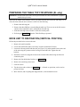
MEASURE PATH TO FINAL DESTINATION .......................................................................................................3-6
Short Doorway ......................................................................................................................................................3-6
Narrow Hallway ....................................................................................................................................................3-7
REMOVE TABLE TOP (IF NECESSARY) .............................................................................................................3-7
REMOVE QDR 4500A, OR SL, C-ARM (IF NECESSARY) ..................................................................................3-8
PREPARING THE TABLE TOP FOR MOVING (SL only) ..................................................................................3-10
MOVE UNIT TO DESTINATION (VERTICAL POSITION) ...............................................................................3-10
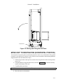
MOVE UNIT TO DESTINATION (HORIZONTAL POSITION)..........................................................................3-11
SET UP UNIT .........................................................................................................................................................3-13
INSTALL QDR 4500A, OR QDR 4500SL, UPPER C-ARM.................................................................................3-15
INSTALL QDR 4500W, OR QDR 4500C, C-ARM ...............................................................................................3-16
INSTALL COMPUTER ..........................................................................................................................................3-17
INSTALL CABLES.................................................................................................................................................3-17
SAFETY PRECAUTIONS ......................................................................................................................................3-18
CHECK POWER LINE VOLTAGE .......................................................................................................................3-18
Measure Line Voltage .........................................................................................................................................3-18
Measure Isolation Transformer Secondary Voltage ............................................................................................3-18
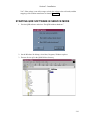
STARTING QDR SOFTWARE IN SERVICE MODE...........................................................................................3-19
CHECK TUBE KV PEAK POTENTIAL................................................................................................................3-20
CHECK TUBE CURRENT.....................................................................................................................................3-22
CHECK BELT TENSION .......................................................................................................................................3-24
ADJUST C-ARM Y BELT......................................................................................................................................3-24
CALIBRATE MOTORS..........................................................................................................................................3-24
CHECK X-RAY BEAM ALIGNMENT .................................................................................................................3-24
CALIBRATE APERTURE (QDR 4500A AND SL)...............................................................................................3-24
CHECK LASER POSITIONING OFFSET.............................................................................................................3-25
ADJUST A/D GAIN CONTROL ............................................................................................................................3-25
PERFORM DETECTOR FLATTENING................................................................................................................3-25
PERFORM LATERAL ALIGNMENT TEST .........................................................................................................3-25
MEASURE X-RAY DOSE TO PATIENT..............................................................................................................3-25
CHECK HVPS/S (TANK) FOR RADIATION LEAKAGE....................................................................................3-26
CALIBRATE FOR AREA, BMD AND BMC ........................................................................................................3-27
TEST SCAN MODES .............................................................................................................................................3-27
FINISH ASSEMBLING UNIT................................................................................................................................3-28
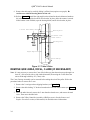
MEASURE X-RAY SCATTER FROM PHANTOM..............................................................................................3-28
PERFORM QC ........................................................................................................................................................3-28
RUN REPRODUCIBILITY TEST ..........................................................................................................................3-29
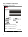
THE RADIATION MEASUREMENT REPORT ...................................................................................................3-30
SECTION 4 ALIGNMENT AND CALIBRATION .........................................................................4-1
TABLE ALIGNMENT ..............................................................................................................................................4-1
Checking Table Alignment....................................................................................................................................4-1
Aligning Table.......................................................................................................................................................4-1
Table Edge to T-Rail (“A” Dimension) Adjustment .........................................................................................4-1
Front to Back T-Rail and Table Edge/Rail Gap Adjustment.............................................................................4-3
C-ARM PARALLELISM ADJUSTMENT (A and SL only).....................................................................................4-3
X-RAY BEAM ALIGNMENT (A and SL only) .......................................................................................................4-4
iv
X-RAY BEAM ALIGNMENT (C and W only) ........................................................................................................4-8
APERTURE CALIBRATION (A and SL only).........................................................................................................4-9
MOTOR CALIBRATION .........................................................................................................................................4-9
MOTOR$TZ (QDR 4500A and SL)....................................................................................................................4-10
MOTOR$AY (all QDR 4500 models).................................................................................................................4-12
MOTOR$TY (QDR 4500A and W) ....................................................................................................................4-16
MOTOR$TX (all QDR 4500 models) .................................................................................................................4-19
MOTOR$AR (QDR 4500A and SL) ...................................................................................................................4-22
LASER POSITIONING OFFSET ADJUSTMENT.................................................................................................4-27
A/D GAIN CONTROL ADJUSTMENT .................................................................................................................4-27
DETECTOR FLATTENING ...................................................................................................................................4-28
TABLE TOP RADIOGRAPHIC UNIFORMITY....................................................................................................4-30
Machines using Body Composition Analysis (BCA) ..........................................................................................4-30
Machines using BMD Whole Body Analysis ......................................................................................................4-31
LATERAL ALIGNMENT TEST (QDR 4500A AND SL) ......................................................................................4-31
CHECK PHANTOM VALUES...............................................................................................................................4-32
AREA, BMD AND BMC CALIBRATION.............................................................................................................4-32
Scan Thickness Measurement & Calibration (QDR 4500A and SL)..................................................................4-33
Scan Thickness Measurement & Calibration (QDR 4500W and C)....................................................................4-34
Calibration of Area and BMC, for Array Scan Modes ........................................................................................4-35
RECALYZE and Add Array AP Scans to the QC Database................................................................................4-36
SECTION 5 REMOVE AND REPLACE PROCEDURES ............................................................5-1
RECOMMENDED TOOLS.......................................................................................................................................5-1
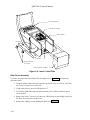
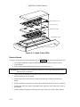
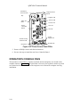
ELECTRONICS TRAY FRUS ..................................................................................................................................5-1
Electronics Tray Printed Circuit Boards................................................................................................................5-1
C-Arm Y Belt ........................................................................................................................................................5-2
C-Arm Y Motor or Gearcase .................................................................................................................................5-3
C-Arm Y Encoder..................................................................................................................................................5-4
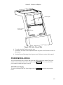
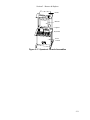
CONTROL PANEL AND TABLE Y FRUS .............................................................................................................5-4
Control Panel.........................................................................................................................................................5-5
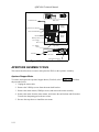
PCBs Under Right-Side of the Table.....................................................................................................................5-5
Table Y Belt ..........................................................................................................................................................5-6
Table Y Motor or Gearcase ...................................................................................................................................5-6
Table Y Encoder....................................................................................................................................................5-7
TABLE X FRUS........................................................................................................................................................5-8
Table X Motor Controller PCB .............................................................................................................................5-8
Table X Belt ..........................................................................................................................................................5-9
Table X Motor or Gearcase .................................................................................................................................5-10
Table X Encoder..................................................................................................................................................5-10
TABLE Z FRUS (A and SL only)............................................................................................................................5-11
Pedestal................................................................................................................................................................5-11
Linear Potentiometer (Encoder- Obsolete) ..........................................................................................................5-13
The Linear Rotary String (Encoder) ....................................................................................................................5-13
Installation ......................................................................................................................................................5-13
ARM R FRUS..........................................................................................................................................................5-15
Motor Controller Board.......................................................................................................................................5-15
Arm R Belt ..........................................................................................................................................................5-16
Arm R Motor, Gearcase, Encoder or Encoder Belt .............................................................................................5-16
Gas Spring ...........................................................................................................................................................5-18
LOWER C-ARM FRUS ..........................................................................................................................................5-18
C-Arm Interface Board ........................................................................................................................................5-18
X-Ray Controller Assembly ................................................................................................................................5-18
Filter Drum Assembly .........................................................................................................................................5-20
Tank Assembly ....................................................................................................................................................5-21
UPPER C-ARM FRUS ............................................................................................................................................5-23
Integrator/Multiplexor Board ..............................................................................................................................5-23
Detector Boards ...................................................................................................................................................5-24
v
Laser Assembly ...................................................................................................................................................5-25
REAR C-ARM FRUS..............................................................................................................................................5-26
Analog to Digital Converter Board .....................................................................................................................5-26
POWER MODULE FRUS ......................................................................................................................................5-27
28 Volt Power Supply .........................................................................................................................................5-27
±15 Volt Power Supply.......................................................................................................................................5-28
Line Filter............................................................................................................................................................5-29
Isolation Transformer ..........................................................................................................................................5-29
Power Controller Board ......................................................................................................................................5-29
OPERATOR'S CONSOLE FRUS ...........................................................................................................................5-30
APERTURE ASSEMBLY FRUS............................................................................................................................5-32
Aperture Stepper Motor ......................................................................................................................................5-32
Aperture Motor PCB ...........................................................................................................................................5-33
Aperture Position Belt.........................................................................................................................................5-33
Rotary Potentiometer...........................................................................................................................................5-34
DRUM ASSEMBLY FRUS ....................................................................................................................................5-34
Drum Encoder PCB.............................................................................................................................................5-34
Drum Belts ..........................................................................................................................................................5-35
Stepper Motor Assembly.....................................................................................................................................5-36
Drum Bearings ....................................................................................................................................................5-37
REPLACING EMI CABLES...................................................................................................................................5-39
FRU LISTS..............................................................................................................................................................5-41
Figure 5-1. Electronics Tray FRUs......................................................................................................................5-41
Figure 5-2. Control Panel and Table Y FRUs .....................................................................................................5-41
Figure 5-3. Left Side Table Y FRUs ...................................................................................................................5-41
Figure 5-4. Table X FRUs...................................................................................................................................5-42
Figure 5-5. Table Z FRUs ...................................................................................................................................5-42
Figure 5-6. Installing the Rotary String Encoder.................................................................................................5-42
Figure 5-7 C-Arm R FRUs (Outside View).........................................................................................................5-42
Figure 5-8. C-Arm R FRUs (Inside View) ..........................................................................................................5-43
Figure 5-9. Lower C-Arm FRUs .........................................................................................................................5-43
Figure 5-11. Upper C-Arm FRUs........................................................................................................................5-43
Figure 5-12. Detector Assembly Mounting .........................................................................................................5-43
Figure 5-13. Laser Assembly...............................................................................................................................5-44
Figure 5-14. Rear C-Arm FRUs ..........................................................................................................................5-44
Figure 5-15. Power Module FRUs ......................................................................................................................5-44
Figure 5-16. Power Control Panel FRUs.............................................................................................................5-44
Figure 5-17. Operator's Console Assemblies.......................................................................................................5-45
Figure 5-18. Computer Assemblies .....................................................................................................................5-46
Figure 5-19. Aperture Assembly FRUs (QDR 4500A and SL) ...........................................................................5-46
Figure 5-22. Front Drum Assembly FRUs ..........................................................................................................5-46
Figure 5-23. Drum Outer Bearings......................................................................................................................5-47
Figure 5-24. Drum Inner Bearings ......................................................................................................................5-47
Cables..................................................................................................................................................................5-47
Miscellaneous......................................................................................................................................................5-47
Mobile .................................................................................................................................................................5-48
Special Tools.......................................................................................................................................................5-48
SECTION 6 FAULT ISOLATION.................................................................................................6-1
BEFORE STARTING ...............................................................................................................................................6-1
SOFTWARE CONFIGURATION.............................................................................................................................6-1
HARDWARE CONFIGURATION ...........................................................................................................................6-1
POWER PROBLEMS ...............................................................................................................................................6-1
MOTION PROBLEMS .............................................................................................................................................6-2
CONTROL PANEL PROBLEMS.............................................................................................................................6-5
DISPLAY PROBLEMS ............................................................................................................................................6-5
Vertical Stripe .......................................................................................................................................................6-5
Horizontal Stripe ...................................................................................................................................................6-6
vi
Noise......................................................................................................................................................................6-6
No Display.............................................................................................................................................................6-7
TARGETING/LASER PROBLEMS .........................................................................................................................6-8
DATA COMMUNICATIONS PROBLEMS .............................................................................................................6-8
AREA /BMD/BMC/CV SPECIFICATION PROBLEMS.........................................................................................6-9
X-RAY PROBLEMS.................................................................................................................................................6-9
No X-Rays.............................................................................................................................................................6-9
X-Ray Alignment Problems.................................................................................................................................6-10
Detector Flattening Problems ..............................................................................................................................6-11
LASER PROBLEMS...............................................................................................................................................6-12
OIL LEAKAGE .......................................................................................................................................................6-13
The Torque Specifications...................................................................................................................................6-13
Tank Top Cover Components and Screw Location .............................................................................................6-13
Tightening the Lexan Cup Screws.......................................................................................................................6-14
Tightening the Bladder Gasket Screws................................................................................................................6-14
Tightening the Transformer Seal Screws.............................................................................................................6-14
Tightening the Tank Cover Gasket Screws..........................................................................................................6-15
MISCELLANEOUS PROBLEMS ..........................................................................................................................6-16
SECTION 7 PREVENTIVE MAINTENANCE...............................................................................7-1
CUSTOMER PREVENTIVE MAINTENANCE ......................................................................................................7-1
FIELD SERVICE PREVENTIVE MAINTENANCE ...............................................................................................7-1
Guide Rail and Bearing Maintenance....................................................................................................................7-3
SECTION 8 PCB SUMMARY INFORMATION ...........................................................................8-1
Power Distribution ................................................................................................................................................8-1
ADC ......................................................................................................................................................................8-1
Signal Distribution ................................................................................................................................................8-2
Communications Controller ..................................................................................................................................8-2
Detector Array Assembly.......................................................................................................................................8-3
TZ Drive ................................................................................................................................................................8-3
Stepper Motor Controller ......................................................................................................................................8-4
Control Panel Controller .......................................................................................................................................8-4
SECTION 9 SOFTWARE TOOLS...............................................................................................9-1
X-Ray Survey ........................................................................................................................................................9-1
vii
TABLE OF FIGURES
Figure 1-1. QDR 4500 ................................................................................................................1-2
Figure 1-2. Q Scan Plot .................................................................................................................1-3
Figure 1-3. QDR 4500 Block Diagram (Operator's Console) .......................................................1-4
Figure 1-4. QDR 4500 Block Diagram (Scanner Unit).................................................................1-5
Figure 1-5. QDR 4500 Block Diagram (C-Arm Subsystem) ........................................................1-6
Figure 2-1. Communications Controller Board/Distribution Board Interconnection Diagram ....2-3
Figure 2-2. Distribution Board High Level Interconnection Diagram..........................................2-4
Figure 2-3. Distribution Board/Motor Controller Board Interconnection Diagram .....................2-6
Figure 2-4. Distribution Board/TZ Drive Board Interconnection Diagram..................................2-9
Figure 2-5. Control Panel Controller Interconnection Diagram ...............................................2-12
Figure 2-6. Distribution Board/C-Arm Interface Board Interconnection Diagram.....................2-16
Figure 2-7. C-Arm Interface Board High Level Interconnection Diagram................................2-18
Figure 2-8. C-Arm Interface Board/X-Ray Controller Assembly Interconnection Diagram....2-19
Figure 2-9. X-Ray Controller Assembly High-Level Interconnection Diagram........................2-21
Figure 2-10. Low Voltage Power Supply Board Interconnections ............................................2-22
Figure 2-11. PFR Substitution Board/I/O and Logic Board Interconnection Diagram .............2-24
Figure 2-12. I/O and Logic Board/H-Bridge Board Interconnection Diagram ..........................2-24
Figure 2-13. I/O and Logic Board/Duty Cycle Driver Board Interconnection Diagram ...........2-25
Figure 2-14. H-Bridge Board/Duty Cycle Driver Board Interconnection Diagram...................2-25
Figure 2-15. Integrator/Multiplexor Board/Solid State Detector Boards Interconnection Diagram2-27
Figure 2-16. Analog Digital Converter Board/Integrator Multiplexor Board Interconnection
Diagram..................................................................................................................2-29
Figure 2-17. C-Arm Interface Board/Analog/Digital Converter Board Interconnection Diagram2-31
Figure 2-18. Power Module Block Diagram..............................................................................2-33
Figure 3-1. Room Layout (4500A)................................................................................................3-2
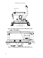
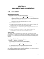
Figure 3-2. System Dimensions (4500SL) ....................................................................................3-3
Figure 3-3. System Dimensions (4500W).....................................................................................3-3
Figure 3-4. System Dimensions (4500C) ......................................................................................3-4
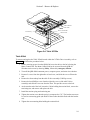
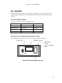
Figure 3-5. Crated Unit (QDR 4500A and QDR 4500SL) ...........................................................3-5
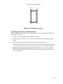
Figure 3-6. Uncrated Unit (QDR 4500A and QDR 4500 SL) ......................................................3-7
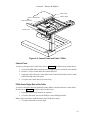
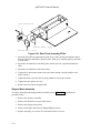
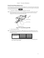
Figure 3-7. Table X Drive.............................................................................................................3-8
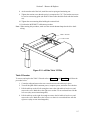
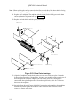
Figure 3-8. Tipping Unit ...............................................................................................................3-9
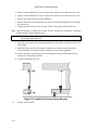
Figure 3-9. Moving and Tilting the Unit Down ..........................................................................3-11
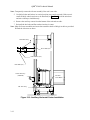
Figure 3-10. Auxiliary Horizontal Caster Installation ................................................................3-12
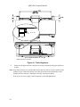
Figure 3-11. Shipping Bracket Locations (QDR 4500A and SL) ...............................................3-13
Figure 3-12. Shipping Bracket Locations (QDR 4500A and SL) ...............................................3-14
Figure 3-13. Shipping Bracket Locations (QDR 4500W and C) ................................................3-14
Figure 3-14. Shipping Bracket Location (QDR 4500W and C)..................................................3-15
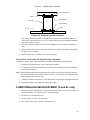
Figure 3-15. Repositioning the Belt Tensioning Mechanism .....................................................3-16
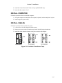
Figure 3-16. Isolation Transformer Taps ....................................................................................3-17
Figure 3-17. Peak Potential Mode 4............................................................................................3-21
Figure 3-18. Peak Potential Mode 3............................................................................................3-21
Figure 3-19. Tube Current Mode 1 .............................................................................................3-23
viii
Figure 3-20. Tube Current Mode 3 .............................................................................................3-23
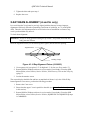
Figure 3-21. Leakage Test Shield (099-0566) ............................................................................3-27
Figure 4-1. Table Alignment.........................................................................................................4-2
Figure 4-2. Pedestal (covers removed)..........................................................................................4-3
Figure 4-3. X-Ray Alignment Fixture (010-0923)........................................................................4-4
Figure 4-4. Inserting The X-Ray Alignment Fixture ....................................................................4-5
Figure 4-5. The Alignment Fixture Properly Installed..................................................................4-6
Figure 4-6. Filter Drum Adjustments - Top View ........................................................................4-6
Figure 4-7. Array Assembly - Top View, Partial..........................................................................4-7
Figure 5-1. Electronics Tray FRUs ...............................................................................................5-3
Figure 5-2. Control Panel and Table Y FRUs...............................................................................5-5
Figure 5-3. Left Side Table Y FRUs.............................................................................................5-7
Figure 5-4. Table X FRUs.............................................................................................................5-9
Figure 5-5. Table Z FRUs ...........................................................................................................5-12
Figure 5-6. Installing the Rotary String Encoder ........................................................................5-14
Figure 5-7 C-Arm R FRUs (Outside View) ................................................................................5-15
Figure 5-8. C-Arm R FRUs (Inside View)..................................................................................5-17
Figure 5-9. Lower C-Arm FRUs .................................................................................................5-20
Figure 5-10. Top View of Tank ..................................................................................................5-22
Figure 5-11. Upper C-Arm FRUs................................................................................................5-24
Figure 5-12. Detector Assembly Mounting.................................................................................5-25
Figure 5-13. Laser Assembly ......................................................................................................5-26
Figure 5-14. Rear C-Arm FRUs ..................................................................................................5-27
Figure 5-15. Power Module FRUs ..............................................................................................5-28
Figure 5-16. Power Control Panel FRUs ....................................................................................5-30
Figure 5-17. Operator's Console Assemblies ..............................................................................5-31
Figure 5-18. Computer Assemblies.............................................................................................5-32
Figure 5-19. Aperture Assembly FRUs (QDR 4500A and SL) ..................................................5-33
Figure 5-20. Aperture Assembly Removal (QDR 4500A and SL) .............................................5-35
Figure 5-21. Rear Drum Assembly FRUs ...................................................................................5-36
Figure 5-22. Front Drum Assembly FRUs..................................................................................5-37
Figure 5-23. Drum Outer Bearings .............................................................................................5-38
Figure 5-24. Drum Inner Bearings ..............................................................................................5-39
Figure 5-25. The EMI Compliance Cable...................................................................................5-40
Figure 6-1. Scanner Motion Directions.........................................................................................6-3
Figure 6-2. Checking C-Arm Parallelism....................................................................................6-10
Figure 6-3 Tank Assembly Top view..........................................................................................6-13
Figure 6-4 Lexan Cup Screw Tightening Order .........................................................................6-14
Figure 6-5. Bladder Gasket Screws.............................................................................................6-14
Figure 6-6. Transformer Screws .................................................................................................6-15
Figure 6-7. Tank Cover Gasket ...................................................................................................6-16
Figure 7-1. Guide Bearing and Rail ..............................................................................................7-3
Figure 9-1. X-RAY SURVEY Screen−X-Rays OFF ....................................................................9-2
Figure 9-2. X-RAY SURVEY Screen−X-Rays ON......................................................................9-2
Figure 9-3. X-RAY SURVEY Screen Settings.............................................................................9-3
ix
SECTION 1
INTRODUCTION
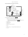
SYSTEM OVERVIEW
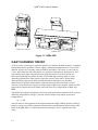
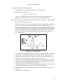
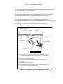
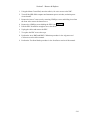
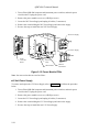
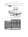
The Hologic QDR4500 X-ray Bone Densitometer (Figure 1-1) estimates the bone mineral
content (BMC) and bone mineral density (BMD) of selected areas of the body, or of the entire
skeleton. It does so using X-rays of two different energy levels. This dual-energy scheme allows
soft tissue within the selected area to be subtracted out, leaving only bone to be scanned and
estimated.
Note: This manual uses "QDR 4500" to refer to all models in the QDR 4500 QDR for Windows
series systems. Information presented in this manual, that applies only to a particular
model, or models, will be noted as such.
The patient lies face up on the table and, with the aid of a cross-hair laser, the operator positions
the scanning arm over the region of interest. After entering patient data and selecting the type
and size of scan desired, the operator initiates the scan with a single keystroke.
The operator is not required to select technique factors, as tube current and voltage are preselected and fixed. Since testing is performed by fan beam method rather than by flooding the
area as in conventional radiography, the scanning time is a function of the dimensions of the area
to be measured, the desired resolution and the desired precision.
BMC results are expressed in grams of calcium hydroxyapatite, and BMD is reported in
grams/cm2 of the same compound.
Note: In most cases, no additional shielding is necessary for patient, operator or room, and the
QDR 4500 QDR for Windows can be placed in any convenient non-shielded examination
room. Contact your state regulatory agency for details about additional shielding
requirements, if any.
The QDR 4500 QDR for Windows employs a patented Automatic Internal Reference System,
which continuously calibrates the machine to eliminate the effects of variations in temperature,
tube flux, etc. No daily calibration is required. The daily scanning of a quality control phantom is
required to provide assurance that the system is functioning correctly, and to aid in the detection
of any long-term drift.
The X-ray scans produced by the QDR 4500 QDR for Windows, and displayed on the monitor,
are intended only to locate anatomical sites for measurement, and to assure the operator that the
machine is operating properly. They are not intended as a substitute for conventional film-based
diagnostic scans.
1-1
QDR® 4500 Technical Manual
Operator's Console
Scanner Unit
Figure 1-1. QDR 4500
X-RAY SCANNING THEORY
An X-ray source, consisting of a generator and tube in a common, shielded enclosure, is mounted
beneath the patient. It generates a narrow, tightly collimated, fan shaped beam of X-rays which
alternate, at power line frequency, between 100kVp and 140kVp. The source is at one end of a
C-arm. At the other end, above the patient, is a crystal/solid state detector. During a scan, the Carm and table move under computer control to guide the beam over the desired scan area.
Before passing through the patient, the beam is filtered through a rotating drum, in which
alternating segments have radio-opacities equivalent to tissue, bone and air. When finally
intercepted by the detector, the beam contains information about the X-ray absorbing
characteristics of both the patient and the calibration materials in the filter drum. An A/D
converter, fed by the detector, supplies a complex digital signal to the computer, which uses that
signal both to construct the screen display and as the basis for its computations of BMC and
BMD.
The QDR 4500 computer algorithm is based on the principle that bone attenuates the X-ray beam
differently at high and low energies. The bone mineral content of any sample point can be
computed from:
Q = L - kH
where H and L are the logarithms of the sample attenuation at high (140kVp) and low (100kVp)
energies, respectively, and the constant k depends on the tissue attenuation characteristics of the
beam. In the QDR 4500, k is continuously measured using the “tissue” segment in the filter
wheel.
1-2
Section 1 - Introduction
The program works in the following manner:
1. Load preliminary scan and obtain regions of interest from operator.
2. Estimate k as an average value of:
k = [Ltissue - Lair] / [Htissue - Hair]
where Ltissue indicates a low-energy measurement with tissue-equivalent material
interposed by the filter drum, and Lair, Htissue and Hair are similarly defined.
Note: The subscript "air" designates the filter drum segment that is empty (i.e., contains neither
bone- nor tissue-equivalent material).
3. Using this value of k, calculate Q for each point scanned using the formula given above
(Q = L - kH). This array of Q values constitutes a "Q scan". Displays the Q scan.
4. Compile a histogram of the Q values. Because a large portion of the scan contains soft
tissue only, this histogram will have a large peak. Choose a threshold value just above
this peak, and apply that value to discriminate, point by point in the Q scan, between
"bone" points (whose Q is above the threshold) and "non-bone" points (whose Q is
below the threshold).
Figure 1-2. Q Scan Plot
5.
Use the "non-bone" points to calculate a baseline value for each scan line. Using these
points, form a new histogram and repeat steps 4 and 5 until the results converge.
6. Smooth the segment boundaries to eliminate isolated noise-generated "bone" points.
7. Display the "bone" and "non-bone" points for operator approval.
8. Determine the constant of proportionality (d0) that relates the Q values to actual BMC
(grams). That constant is determined by measuring how much Q shifts when boneequivalent material is interposed by the filter drum.
9. Calculate the total bone mineral values by adding up the Q values for all "bone" points
in each region of interest (e.g., each vertebra), and multiplying by d0.
10. Determine the bone areas by counting the number of "bone" points in each region of
interest.
11. Calculate bone mineral density as:
1-3
QDR® 4500 Technical Manual
BMD = BMC / area
12. Display the calculated results and print the report.
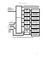
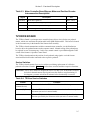
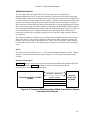
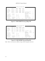
FUNCTIONAL OVERVIEW
This section provides a block diagram of the QDR 4500 system along with a brief functional
overview description of each block. A detailed functional description along with interconnection
diagrams and interconnection descriptions is provided in Section 2.
AC
PRINTER
AC
AC
POWER
STRIP
DISPLAY
TERMINAL
VGA
SCSI INTERFACE
KEYBOARD
OPTICAL/JAZ
DISK(Option)
PHONE
JACK
MODEM
AC IN
POWER
ASSEMBLY
MOUSE
COMMUNICATIONS
CONTROLLER
Computer
15/24V EMERGENCY
28V DC
TO/FROM
INSTRUMENT
DISTRIBUTION
(FIGURE 1.4)
TO/FROM LEFT/RIGHT PEDESTAL DRIVE (FIGURE 1.4)
TO X-RAY CONTROLLER (FIGURE 1.5)
Figure 1-3. QDR 4500 Block Diagram (Operator's Console)
1-4
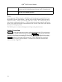
Section 1 - Introduction
TO/FROM C-ARM INTERFACE (FIGURE 1-5)
TO/FROM
COMMUNICATION
CONTROLLER
DISTRIBUTION
15/24V
EMERGENCY
28V DC
TO/FROM
POWER
MODULE
CONTROL
PANEL
CONTROLLER
CONTROL PANEL
TX STEPPER
MOTOR
DRIVER
TABLE IN/OUT
MOTOR AND
POSITION ENCODER
TY STEPPER
MOTOR
DRIVER
TABLE LEFT/RIGHT
MOTOR AND
POSITION ENCODER
AR STEPPER
MOTOR
DRIVER
C_ARM ROTATION
MOTOR AND
POSITION ENCODER
AY STEPPER
MOTOR
DRIVER
C_ARM CARRIAGE
MOTOR AND
POSITION ENCODER
TZ DRIVE
MOTOR
CONTROLLER
LEFT/RIGHT PEDESTAL
PEDESTAL LEFT
MOTOR AND
POSITION ENCODER
PEDESTAL RIGHT
MOTOR AND
POSITION ENCODER
Figure 1-4. QDR 4500 Block Diagram (Scanner Unit)
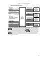
1-5
QDR® 4500 Technical Manual
LASER
ASSEMBLY
ANALOG TO
DIGITAL
CONVERTER
TO/FROM
DISTRIBUTION
INTEGRATOR
MULTIPLEXOR
SILICON
DETECTORS
APERTURE
MOTOR AND
SENSOR
C-ARM
INTERFACE
DRUM
MOTOR AND
ENCODER PICKUP
FROM POWER MODULE
X_RAY
CONTROLLER
X_RAY
SOURCE
UNIT
Figure 1-5. QDR 4500 Block Diagram (C-Arm Subsystem)
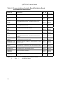
Block
Description
Computer
Controls and commands all QDR 4500 hardware modules.
Communications
Controller
Controls the flow of commands to and from the Scanner modules via the
communications bus.
Distribution Board
Provides the interconnections between the QDR 4500 Operator's Console
and the Scanner.
Control Panel
Controller
Interfaces the Scanner’s Control Panel to the Operator's Console
computer software.
Control Panel
Provides switches (with visual indicators) for moving the Scanner’s CArm and Patient Table. Also provides an Emergency Stop switch.
TZ Drive Motor
Controller
Controls the motion of the Patient’s Table left and right pedestal motors
based on commands from the computer software.
1-6
Section 1 - Introduction
Table Up/Down
Motor and Position
Encoder
Raises or lowers the Patient Table and provides position monitoring.
TX Stepper Motor
Driver
Controls the motion of the Patient’s Table in and out motor based on
commands from the computer software.
Table In/Out Motor
and Position
Encoder
Moves the Patient Table in and out and provides position monitoring.
TY Stepper Motor
Driver
Controls the motion of the Patient’s Table left and right motor based on
commands from the computer software.
Table Left/Right
Motor and Position
Encoder
Moves the Patient Table left and right and provides position monitoring.
AR Stepper Motor
Driver
Controls the motion of the C-Arm rotation motor based on commands
from the computer software.
C-Arm Rotation
Motor and Position
Encoder
Rotates the C-Arm and provides position monitoring.
AY Stepper Motor
Driver
Controls the motion of the C-Arm left and right motor based on
commands from the computer software.
C-Arm AY Motor
and Position
Encoder
Moves the C-Arm left and right and provides position monitoring.
C-Arm Interface
Controls the Aperture and Filter Drum motors, generates timing signals
for the X-Ray Controller and the Data Acquisition System, and provides
power to the Positioning Laser.
X-Ray Controller
Controls the operation of the X-ray source.
X-Ray Source Unit
Generates the X-ray beam.
Solid State Detectors Converts the X-rays into electrical signals.
Integrator/
Multiplexor
Integrates the signals from the Solid State Detectors and applies them to
the Analog to Digital Converter.
Analog to Digital
Converter
Converts the analog signals from the Integrator/Multiplexor to a digital
format.
Positioning Laser
Provides a laser beam to assist in positioning the patient on the Patient
Table.
1-7
QDR® 4500 Technical Manual
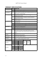
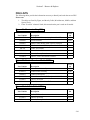
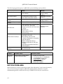
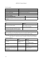
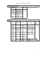
PRODUCT SPECIFICATIONS
SPECIFICATION
Scanning Method:
X-ray System:
Detector System:
MODEL DEFINITION
A,SL
W,C
All
A
SL
C,W
Scanning Sites:
A
SL
W
C
Scan Region:
A,W
SL
C
Scatter Radiation:
All
Multidetector array, Indexing table, and motorized C-arm
Multidetector array, Indexing table, and Arm
Switched Pulse Dual-Energy X-ray tube, operating at 100 and
140kV, 5mA avg. at 50% duty cycle, 2.5mA avg. at 25% duty cycle,
30s maximum, Tungsten target
216 multichannel detector consisting of CdWO4 scintillators
coupled to Silicon diodes
128 multichannel detector consisting of CdWO4 scintillators
coupled to Silicon diodes
64 multichannel detector consisting of CdWO4 scintillators coupled
to Silicon diodes
Lumbar spine (in AP and lateral projections), proximal femur (hip),
and whole body
Lumbar spine (in AP and lateral projections), proximal femur (hip)
Lumbar spine, proximal femur (hip), and whole body
Lumbar spine, proximal femur (hip)
195cm (76.77") x 65cm (25.59")
96cm (38") x 65cm (25.59")
96cm (38") x 51cm (20")
Less than 10µGy/h (1mrad/h) at 2m (79 in.) from the center of the
X-ray beam for all scans except images, which is less than
10µGy/h (1mrad/h) at 3.5m (138 in.) from the center of the X-ray
beam.
The QDR-4500 meets the requirements of 21 CFR 1020.30(k) for
leakage from the X-ray source
Leakage
Radiation:
All
External Shielding
Requirement:
All
Contact state regulatory agency.
Calibration:
All
Self Calibrating using HOLOGIC Automatic Internal Reference
System. Operator calibration NOT required.
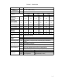
System Weight:
(installed)
(shipping)
1-8
A
SL
W
C
Scanner
365kg
800lb
365kg
800lb
310kg
680lb
295kg
650lb
System
A
660kg
1450lb
SL
660kg
1450lb
W
622kg
1370lb
C
610kg
1340lb
Console
68kg
150lb
Section 1 - Introduction
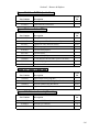
SPECIFICATION
Operating
Temperature:
Humidity:
MODEL DEFINITION
o
o
o
o
All
15 - 32 C (60 - 90 F)
All
20 - 80% relative Humidity, non-condensing
Footprint:
Length
Width
Height
m
inches
m
inches
m
inches
C-arm not
rotated, table not
extended
A
2.02
79.5
1.40
55
1.42
56
C-arm rotated,
table extended
A
3.02
119
1.50
59
1.42
56
C-arm not rotated
SL
2.02
79.5
1.40
55
1.42
56
C-arm rotated
SL
2.02
79.5
1.50
59
1.42
56
table extended
W
3.02
119
1.50
59
1.42
56
table not
extended
W
2.02
79.5
1.22
48
1.42
56
C
2.02
79.5
1.40
55
1.42
56
Average Heat
Load:
ALL
1000w (3400 BTU/hr)
Patient Table
Height:
A,SL
W,C
Adjustable, 71cm (28") from floor when scanning in AP mode
71cm (28”)
Positioning Laser:
All
Laser Diode (<1mW) cross hair, with emergency mechanical
shutter
X-ray Collimation:
A,SL
W,C
Lateral Tracking:
A,SL
C,W
Leakage Current:
Resolution:
All
A/SL
C/W
Selectable by scan type
1.0mm slit
Exam table is capable of moving +/-2.54cm (1.0") in the x-axis
from center location with scan arm in lateral position.
N/A
Normal
<75µA
1 line pair/mm
0.5 line pair/mm
Single Fault <400µA
(approximately 0.5mm)
(approximately 1.0mm)
1-9
QDR® 4500 Technical Manual
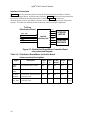
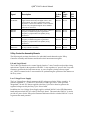
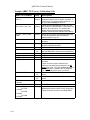
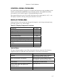
BMD Precision:
EXAM
AP Spine Array
AP Spine Fast
AP Spine High Definition
AP Spine Turbo
Forearm
Hip Array
Hip Fast
Hip High Definition
Hip Turbo
Lateral Spine Array
Lateral Spine Fast
Lateral Spine High Def.
Whole Body
MODEL
All
All
A,SL
A,SL
W,C
A,SL
W,C
All
All
A,SL
A,SL
W,C
A,SL
A,SL
A,SL
A
W
SCAN TIME
(seconds)
60
30
120
10
15
30
30
60
30
120
10
15
240
120
240
180
407
in vivo PRECISION
1.0%
1.0%
1.0%
1.5%
1.5%
1.0%
1.0%
1.0%
1.0%
1.0%
1.5%
1.5%
1.0%
1.0%
1.0%
1.0%
1.0%
DOSE
mGy
mrad
0.20
20.0
0.10
10.0
0.20
20.0
0.07
7.0
0.05
5.0
0.05
5.0
0.10
10.0
0.20
20.0
0.10
10.0
0.20
20.0
0.07
7.0
0.05
5.0
0.70
70.0
0.35
35.0
0.70
70.0
0.01
1.0
0.015
1.5
Duty Cycle:
A
SL,W,C
50% for all scan modes except Whole Body
100% for Whole Body scans
50% for all Scan Modes
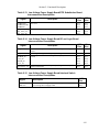
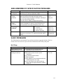
Leakage Technique Factors
The leakage technique factors for all models of QDR 4500’s are the same. It is the maximum
continuous current at the maximum peak potential. This is X-ray mode #3. Peak potential
140/100kVp. (dual energy), current 10mA peak 25% duty cycle or 2.5mA average.
Minimum Beam Filtration
The minimum filtration permanently in the beam is 3.7mm Al equivalent @80kV.
1-10
Section 1 - Introduction
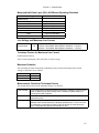
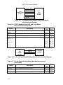
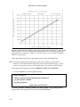
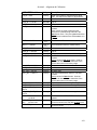
Measured Half Value Layer (HVL) At Different Operating Potentials
Measured operating potential
Measured Half Value Layer
QDR4500A/SL
80kV
100kV
140kV
3.7mm Al equivalent
4.7mm Al equivalent
7.2mm Al equivalent
QDR4500C/W
80kV
100kV
140kV
3.7mm Al equivalent
5.0mm Al equivalent
6.5mm Al equivalent
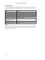
Line Voltage and Maximum Line Current
Power
Requirements:
All
100VAC 16A 50/60Hz, Max apparent resistance = 0.32 ohm
120VAC 14A 50/60Hz, Max apparent resistance = 0.32 ohm
230VAC 8A 50/60Hz, Max apparent resistance = 1.28 ohm
Technique Factors for Maximum Line Current
Peak Potential 140kVp
Tube Current 10mA peak, 50% duty factor or 5mA average.
Maximum Deviation
The maximum deviation from the pre-indication given by labeled technique factor control
settings or indicators are as follows:
Peak Potential:
Current:
Time :
+/- 15%
+/- 40%
+/- 10%
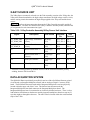
Measurement Criteria for Technique Factors
The measurement criteria of the technique factors is as follows:
Peak Potential:
Current:
Time:
The voltage peak is measured with an oscilloscope. Voltage is a square pulse.
Peak is defined as the peak voltage of the 4 millisecond pulse shape, not
counting any initial overshoot.
Current is measured with an oscilloscope on the last millisecond of the 4
millisecond pulse.
Time of each pulse is measured with an oscilloscope and defined as the time
between 50% rise and fall times of the peak potential pulse. Time of the scan
is measured by counting the number of AC line pulses from the start to the
end. X-ray pulses are synchronous with the AC line.
1-11
SECTION 2
FUNCTIONAL DESCRIPTION
This section provides a detailed functional description along with interconnection diagrams and
descriptions of the Hologic QDR 4500. Refer to Section 1 for a block diagram and a brief
functional description of each block.
COMPUTER
The QDR 4500 Scanner interfaces to an ISA Bus computer to control table and C-arm movement
and X-ray generation, perform all necessary calculations, and manage patient and QC database
information.
The computer is a Pentium-based (or higher) PC compatible that comes equipped with 3.5-inch
floppy disk and hard disk drives, keyboard, color monitor, and an optional Iomega 1GB JAZ
drive. For details pertaining to the computer and its associated components, please refer to the
documentation shipped with each unit.
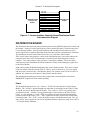
COMMUNICATIONS CONTROLLER BOARD
The Communications Controller board handles all the communications between the Computer
and the Scanner’s C-Arm and Table assemblies. The board resides in one of the computer
internal slots and interfaces with the computer via the computer's I/O bus. It connects to the
Scanner’s Distribution board through a 50-conductor ribbon cable. This cable contains two
independent communications links (one asynchronous and one synchronous) and additional
system control signals. Each signal requires a pair of conductors for differential (RS422) noise
immunity.
The asynchronous communications link communicates with the Motor Controller boards (TX,
TY, AY and AR), the TZ Drive board, the C-Arm Interface board, and the Control Panel
Controller board. The synchronous communications link communicates with the Data
Acquisition System (DAS).
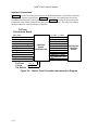
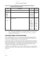
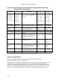
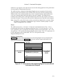
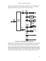
Interface Connections
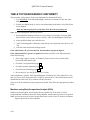
Table 2-1 describes the interconnections between the Communications Controller board and the
Distribution board. The table also identifies the interconnection connector and pin assignments.
Figure 2-1 shows the interconnections between the Communications Controller board and the
Distribution board.
2-1
QDR® 4500 Technical Manual
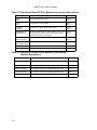
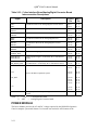
Table 2-1. Communications Controller Board/Distribution Board
Interconnection Descriptions
Signal Pair
Description
1
2
CC Pin
Dist Pin
ATD+
ATD-
Asynchronous data to the Scanner.
JP1-2
JP1-27
JP10-3
JP10-4
STD+
STD-
Synchronous data to the Scanner.
JP1-28
JP1-4
JP10-6
JP10-7
STCLK+
STCLK-
Synchronous data clock from Communications Controller
board to Distribution board. Synchronizes data to the
Scanner.
JP1-5
JP1-30
JP10-9
JP10-10
STFRM+
STFRM-
Synchronous data frame from Communications Controller
board to Distribution board.
JP1-31
JP1-7
JP10-12
JP10-13
ARD+
ARD-
Asynchronous Data from the Scanner.
JP1-8
JJP1-33
JP10-15
JP10-16
SRD+
SRD-
Synchronous Data from the Scanner.
JP1-34
JP1-10
JP10-18
JP10-19
SRCLK+
SRCLK-
Synchronous data clock from Communications Controller
board to Distribution board. Synchronizes data from the
Scanner.
JP1-11
JP1-36
JP10-21
JP10-22
SRFRM+
SRFRM-
Synchronous data frame from Distribution board to
Communications Controller board.
JP1-37
JP1-13
JP10-24
JP10-25
EMERGENCY_IN+
EMERGENCY_IN-
Signals an emergency condition. Generated by the C-Arm
Interface board.
JP1-14
JP1-39
JP10-27
JP10-28
ZEROX+
ZEROX-
AC line zero-crossing signal used for system wide
synchronization. Generated by the C-Arm Interface board.
JP1-40
JP1-16
JP10-30
JP10-31
INTEGRATE+
INTERGATE-
Synchronous signal for Detector Integrate period.
Generated by the C-Arm Interface board.
JP1-17
JP1-42
JP10-33
JP10-34
SYSRESET+
SYSRESET-
Resets the Scanner controllers.
JP1-20
JP1-45
JP10-39
JP10-40
EMERGENCY+
EMERGENCY-
Removes power from the Scanner’s motor drivers and the
X-ray system
JP1-49
JP1-25
JP10-48
JP10-49
Note:
2-2
1.
2.
CC
Dist
=
=
Communications Controller board.
Distribution board.
Section 2 - Functional Description
ATD+, ATDSTD+, STDSTCLK+, STCLKSTFRM+, STFRMARD+, ARD-
COMMUNICATIONS
CONTROLLER
BOARD
SRD+, SRDSRCLK+, SRCLK-
DISTRIBUTION
BOARD
SRFRM+, SRFRMEMERGENCY_IN+, EMERGENCY_INZEROX+, ZEROXINTEGRATE+, INTEGRATESYSRESET+, SYSRESETEMERGENCY+, EMERGENCY-
Figure 2-1. Communications Controller Board/Distribution Board
Interconnection Diagram
DISTRIBUTION BOARD
The Distribution board provides interconnections between the QDR 4500 Operator's Console and
the Scanner. It passes several signal and power lines from the Operator's Console directly to the
C-Arm Interface module. It also provides buffering and individual drivers and receivers for
various signal lines to and from individual Scanner modules and the Communications Controller.
The Distribution board is located in the Electronics Tray in the base of the Scanner.
Three cables connect the Operator's Console to the Distribution board. One cable connects the
communications buss to the Communications Controller located in the Operator's Console
computer. Two cables connect to the Operator's Console Power Module. These two cables
connect power to the Distribution board and connect the X-Ray On and Emergency signal lines
to the Power Module.
Eight cables connect the Distribution board to the various Scanner boards. Four cables connect
to the four Motor Controller boards (Table X, Table Y, Arm R, and Arm Y). Two (one signal
and one power) connect to the C-Arm Interface board. One connects to the TZ Drive board. In
addition, one connects to the Scanner's Control Panel Controller board.
The Distribution board has provision for three jumpers that can be installed to override the
EMERGENCY signal lines when trouble-shooting.
Power
The Distribution board receives +28, +24 and +/-15VDC from the Operator's Console Power
Module. The +28VDC is applied through four individual circuit breakers to the Table X, Table
Y, Arm R, and Arm Y Motor Controller boards. The +24 and +/-15VDC are passed to the CArm Interface board. +24VDC is also applied through a circuit breaker to the Table Z Drive
board. It is also reduced to +7 and + 5VDC by regulators to power op-amplifiers and analog
switches located on this board. The + 7VDC is passed to the Table Z Drive and Control Panel
Controller boards. The + 5VDC powers the digital section of the Distribution board. The +28
and +24VDC power supplies are not closely regulated and their outputs may range from +24V to
+ 35V under normal conditions.
2-3
QDR® 4500 Technical Manual
Note: +7VDC may measure anywhere from +6.25VDC to +7.25VDC. This is true everywhere
+7VDC is shown in this manual.
Six green LEDs indicate the status of the +28, +24, +15, -15, +7 and +5VDC (ON indicates the
respective voltage is present). Five red LEDs indicate the status of the five circuit breakers
applying voltage to the motor drivers/controller. ON indicates the circuit breaker has detected an
over-current condition.
Interface Connections
Figure 2-2 shows boards that connect to the Distribution board.
OPERATOR’S
CONSOLE
COMPUTER
INSTRUMENT
C-ARM
INTERFACE
BOARD
COMMUNICATIONS
CONTROLLER
BOARD
CONTROL PANEL
CONTROLLER
BOARD
TZ
DRIVE
BOARD
OPERATOR’S
CONSOLE
POWER MODULE
+24 VDC, +/-15VDC,
EMERGENCY
SIGNAL LINES
DISTRIBUTION
BOARD
TX MOTOR
CONTROLLER
BOARD
TY MOTOR
CONTROLLER
BOARD
+28 VDC
AR MOTOR
CONTROLLER
BOARD
AY MOTOR
CONTROLLER
BOARD
Figure 2-2. Distribution Board High Level Interconnection Diagram
2-4
Section 2 - Functional Description
MOTOR CONTROLLER BOARD
The Motor Controller board is a microprocessor controlled power driver circuit for use with a
two-coil bipolar stepper motor. It receives high level commands through the Distribution Board
from the host computer, and applies 28-volt pulses to the stepper motor windings. The QDR
4500 uses four identical Motor Controller boards to control and drive the Table X (Table In/Out),
Table Y (Table Left/Right), C-Arm Rotate, and C-Arm Y (C-Arm Left/Right) stepper motors.
The motor windings are driven by two integrated H-bridges. These integrated circuits provide
internal level conversion and power limiting. Their logic level control inputs are driven from a
stepper motor control microcircuit that receives commands from the microprocessor. The control
circuit senses the current in the motor windings and adjusts the duty cycle of the applied voltage
in such a way as to limit the maximum motor current. The maximum value is determined by an
8-bit control word at a Digital to Analog Converter.
Each Motor Controller board monitors the position of its respective mechanism using a signal
received from an associated Position Encoder connected to the mechanism. The Position Encoder
is a precision potentiometer that divides a +/-3V reference source into a sense amplifier in
proportion to the position of the mechanism driven by the motor. The sense amplifier output is
converted to digital code that provides position feedback to the microprocessor.
The Motor Controller boards receive movement commands from the QDR 4500 computer via the
communications bus. Each Motor Controller board contains an ID switch and four status
indicators (LEDs). The ID switch is a 16-position rotary encoded switch (SW1) that is read
during system initialization to determine the Motor Controller board's address for communicating
with the QDR 4500 computer. ID switch settings for the four Motor Controller boards are as
follows:
Table X drive
4
Table Y drives
5
C-Arm Rotate drive 6
C-Arm Y drive
7
The four red status LEDs provide visual indications of motor drive power on, Stepper CPU
active, motor drive direction, and motor step pulses.
The Motor Controller board also has provision (JP2) for connecting limit switches to inhibit
motor operation when the mechanism goes beyond established mechanical limits. This feature is
not used in the QDR 4500 and therefore no cable is connected to JP2.
Power
Power input to the Motor Controller board is +28VDC. This voltage provides the motor drive
power and is converted down to +5VDC for use by logic circuits on the board. The +5VDC is
also converted to -5VDC. Two green LEDs provide visual indication of the power present on the
Motor Controller board.
2-5
QDR® 4500 Technical Manual
Interface Connections
Figure 2-3 shows the interconnections between the Distribution board, the Motor Controller
boards, the Stepper Motors, and the Position Encoders. Table 2-1 describes the interconnections
between the Distribution board and the Motor Controller. Table 2-3 describes the
interconnections between each Motor Controller and its respective stepper motor and position
encoder. The tables also identify the interconnection connector and pin assignments.
To/From
Distribution Board
(
)
(
)
ATD+, ATDSYSRESET+, SYSRESET+28V
STEPPER
MOTOR
(
)
ARD+, ARD-
MOTOR
CONTROLLER
(
)
+REF
POSITION
ENCODER
(
)
28V_RET
-REF
Figure 2-3. Distribution Board/Motor Controller Board
Interconnection Diagram
Table 2-2. Distribution Board/Motor Controller Board
Interconnection Descriptions
Signal
2-6
Description
Table
X
Table
Y
C-Arm
Rotate
C-Arm
Y
Pin(s)
ARD+
ARD-
Asynchronous Receive Data.
JP7
JP5
JP8
JP11
11
12
ATD+
ATD-
Asynchronous Transmit Data.
JP7
JP5
JP8
JP11
14
15
SYSRST+
SYSRST-
System Reset. Resets the Motor
Controller board.
JP7
JP5
JP8
JP11
17
18
28V
28V_RET
DC power for the Motor
Controller board.
JP7
JP5
JP8
JP11
2,3,4,5
1,6,7,8
Section 2 - Functional Description
Table 2-3. Motor Controller Board/Stepper Motor and Position Encoder
Interconnection Descriptions
Signal
Description
Pin
(No label)
Motor drive signals (4).
JP5-1 - JP5-4
+REF
Precision positive voltage to position potentiometer.
JP3-1
(No label)
Position encoder wiper return voltage.
JP3-3
-REF
Precision negative voltage to position potentiometer.
JP3-5
TZ DRIVE BOARD
The TZ Drive Board is a microprocessor controlled power driver circuit for the two pedestal
motors, which raise and lower the patient table in the QDR 4500A and SL. This board is located
in the electronics tray in the bottom of the Scanner base assembly.
The TZ Drive board communicates with the communications controller, via the Distribution
board, to drive the pedestal motors under computer control. Manual raising of the pedestal may
be required in case of an emergency. In this case, manual control is provided through the Table
switch of the Scanner’s Operator Control Panel.
The TZ Drive board monitors the position of each pedestal using signals received from an
associated Position Encoder connected to the respective pedestal.
Service Switches
The TZ Drive board contains four service switches used during replacement of a defective
pedestal or Position Encoder. Table 2-4 describes these switches and their respective functions.
CAUTION: The TZ drive motors are designed to run at a 5% duty cycle. If the motors overheat,
the built-in thermal cutouts may trip and cause the motors to stop functioning. If
this happens, you must wait about 20 minutes before functionality is restored.
Table 2-4. TZ Drive Service Switches
Switch
Function
Mode
(Normal/Service)
Determines whether the TZ Drive is in Normal or Service operation.
Direction (Up/Down)
When the TZ drive is in Service mode, determines the direction of pedestal
movement (not active in normal mode).
Left
When the TZ drive is in Service mode, moves the left pedestal in the
direction specified by the Direction switch (not active in normal mode).
2-7
QDR® 4500 Technical Manual
Right
When the TZ drive is in Service mode, moves the right pedestal in the
direction specified by the Direction switch (not active in normal mode).
Reset
Resets the board after manual operation. The TZ Drive board must be
reset after any manual operation.
Power
Power input to the TZ Drive board is +24VDC from the Distribution board and 240VAC from
the Operator's Console Power Module. +24VDC powers circuitry located on this board and is
reduced to +5VDC. +5VDC is converted to -5VDC and +/-3VDC. The +5and -5VDC powers
logic circuitry on this board, while the +/- 3VDC provides the reference voltage for the position
sensors. Two green LEDs provide visual indication of the +24 and +5VDC status (ON indicates
the respective voltage is present).
The 240VAC power is connected through control relays to the pedestal motors.
Interface Connections
Figure 2-4 shows the interconnections between the Distribution board, the TZ Drive Board, the
Pedestal Motors, and the Pedestal Position Encoders. Table 2-5 describes the interconnections
between the Distribution board and the TZ Drive Board. Table 2-6 describes the line voltage
(240VAC, line to line) between the Operator's Console Power Module and the TZ Drive Board.
Table 2-7 describes the interconnections between the TZ Drive Board and the two pedestal
motors and their respective position encoders. The tables also identify the interconnection
connector and pin assignments.
2-8
Section 2 - Functional Description
To/From Distribution Board
120V(A)_UP_LEFT
120V(A)_DWN_LEFT
120V(B)_LEFT
GND_PED
ARD+, ARDATD+, ATDSYSRESET+,
EMERGENCY+,
MAN_UP*, MAN_UP_RET
MAN_DOWN*, MAN_DOWN_RET
+3.0VREF
(Position Signal)
-3.0VREF
+24V
To/From
Operator’s Console
Power Module
120V(A)_RIGHT
120V(B)_RIGHT
GND_PED
120V(A)_LEFT
120V(B)_LEFT
GND_PED
TZ
DRIVE
BOARD
120V(A)_UP_RIGHT
120V(A)_DWN_RIGHT
120V(B)_RIGHT
GND_PED
+3.0VREF
(Position Signal)
-3.0VREF
LEFT
PEDESTAL
MOTOR
LEFT
PEDESTAL
POSITION
ENCODER
RIGHT
PEDESTAL
MOTOR
RIGHT
PEDESTAL
POSITION
ENCODER
Figure 2-4. Distribution Board/TZ Drive Board Interconnection Diagram
Figure 2-4 shows the interconnections between the Distribution board, the TZ Drive Board, the
Pedestal Motors, and the Pedestal Position Encoders. Table 2-5 describes the interconnections
between the Distribution board and the TZ Drive Board. Table 2-6 describes the line voltage
(240VAC line to line) between the Operator's Console Power Module and the TZ Drive Board.
Table 2-7 describes the interconnections between the TZ Drive Board and the two pedestal
motors and their respective position encoders. The tables also identify the interconnection
connector and pin assignments.
2-9
QDR® 4500 Technical Manual
Table 2-5. Distribution Board/TZ Drive Board Interconnection Descriptions
Signal
ARD+
ARDATD+
ATDSYSRST+
SYSRSTEMERGENCY+
EMERGENCYMAN_UP*
MAN_UP_RET
MAN_DWN*
MAN_DWN_RET
+24V
+6.5V
Description
Asynchronous Receive Data.
Asynchronous Transmit Data.
System Reset. Resets the TZ Drive board.
Enables manual operation of the pedestals in the case
of an emergency (under control of the Control Panel
Table switch on the Patient Table).
Raises the Patient Table in the case of an emergency.
Lowers the Patient Table in the case of an emergency.
DC power for the Motor Controller board.
Not used.
Pin(s)
JP1-11
JP1-12
JP1-14
JP1-15
JP1-17
JP1-18
JP1-20
JP1-21
JP1-23
JP1-24
JP1-26
JP1-27
JP1-5, JP1-6
JP1-2, JP1-3
Table 2-6. Operator's Console Power Module/TZ Drive Board
Interface Descriptions
Signal
2-10
Description
Pin
120V(A)_LEFT
AC voltage (120) to drive the Left Pedestal motor.
JP6-4
120V(B)_LEFT
AC voltage (120) to drive the Left Pedestal motor.
JP6-5
120V(A)_RIGHT
AC voltage (120) to drive the Right Pedestal motor.
JP6-1
120V(B)_RIGHT
AC voltage (120) to drive the Right Pedestal motor.
JP6-2
GND_PED
Ground line to the Left/Right Pedestal motor.
JP6-3/JP6-6
Section 2 - Functional Description
Table 2-7. TZ Drive Board/Pedestal Motors and Position Encoders
Interconnection Descriptions
Signal
Description
Pin
120V(A)_UP_LEFT
AC voltage to the Left Pedestal motor to move the left
end of the Patient Table up.
JP5-1
120V(A)_DWN_LEFT
AC voltage to the Left Pedestal motor to move the left
end of the Patient Table down.
JP5-2
120V(B)_LEFT
AC line to the Left Pedestal motor.
JP5-3
GND_PED
Ground line to the Left Pedestal motor.
JP5-4
120V(A)_UP_RIGHT
AC voltage to the Right Pedestal motor to move the
right end of the Patient Table up.
JP4-1
120V(A)_DWN_RIGHT
AC voltage to the Right Pedestal motor to move the
right end of the Patient Table down.
JP4-2
120V(B)_RIGHT
AC line to the Right Pedestal motor.
JP4-3
GND_PED
Ground line to the Right Pedestal motor.
JP4-4
+3.0VREF
Precision positive voltage to Left/Right Pedestal
position encoder potentiometer.
JP3-1/JP2-1
(Position Signal)
Left/Right pedestal position encoder wiper return
voltage.
JP3-3/JP2-3
-3.0VREF
Precision negative voltage to Left/Right Pedestal
position encoder potentiometer.
JP3-4/JP2-4
CONTROL PANEL CONTROLLER BOARD
The Control Panel Controller board interfaces the Scanner’s Operator Control Panel to the
computer software allowing the software to determine the state of the Operator Control Panel
switches and to define the state of the various Operator Control Panel LEDs. The board is
located under the right side of the Patient Table assembly near the Operator Control Panel.
The Control Panel Controller communicates with the Operator's Console computer using the
asynchronous communications signals, ARD and ATD, of the communications bus, and the
system control signals SYSRESET, XRAY_LIGHT, and EMERGENCY. It also communicates
the state of the manual Table Up switch to the TZ board and it monitors the state of the C-Arm’s
Tilt switch.
Power
The Control Panel Controller board receives +7VDC from the Distribution board. The +7 is
reduced to +5VDC to power the circuitry on this board and is applied to the Operator Control
Panel to power its LEDs. A green LED, on this board, provides visual indication of the +5VDC
power (ON indicates the voltage is present).
2-11
QDR® 4500 Technical Manual
Interface Connections
Figure 2-5 shows the interconnections between the Distribution board, Control Panel Controller
board and the Operator Control Panel. Table 2-8 describes the interconnections between the
Distribution board and the Control Panel Controller. Table 2-9 describes the interconnections
between the Control Panel Controller and the Operator Control Panel. The tables also identify
the interconnection connector and pin assignments.
To/From
Distribution Board
ARD+, ARD-
L0_PWR* - L7_PWR*
ATD+, ATD-
TZ_PWR*
SYSRESET+, SYSRESET-
XRAY_LIGHT_PWR*
EMERGENCY+, EMERGENCY-
SW0 - SW2
XRAY_LIGHT+, XRAY_LIGHTMAN_TZ_UP
MAN_TZ_UP_RET
CONTROL
PANEL
CONTROLLER
SR0 - SR2
MAN_TZ_UP
MAN_TZ_UP_RET
MAN_TZ_DOWN
MAN_TZ_DOWN
MAN_TZ_DOWN_RET
MAN_TZ_DOWN_RET
EMERBENCY_PANEL
EMERGENCY_PANEL
HW_EMERGENCY_RET
HW_EMERGENCY_RET
+7V
+5V
To/From
C-Arm
Tilt Switch
OPERATOR
CONTROL
PANEL
TILT_A
TILT_B
Figure 2-5. Control Panel Controller Interconnection Diagram
2-12
Section 2 - Functional Description
Table 2-8. Distribution Board/Control Panel Controller Interconnection
Descriptions
Signal
Description
Pin
ARD+
ARD-
Asynchronous Receive Data from
Controller via the Distribution board.
the
Communications
JP2-4
JP2-5
ATD+
ATD-
Asynchronous Transmit Data to the Communications Controller
via the Distribution board
JP2-7
JP2-8
SYSRESET+
SYSRESET-
System Reset from the Communications Controller via the
Distribution board. Resets the Control Panel Controller.
JP2-10
JP2-11
EMERGENCY+
EMERGENCY-
Emergency TZ drive indicator from the Communications
Controller via the Distribution board.
JP2-13
JP2-14
XRAY_LIGHT+
XRAY_LIGHT-
X-Ray Light from the X-Ray Controller via the C-Arm Interface
and Distribution boards.
JP2-16
JP2-17
EMERGENCY_CPANEL
HW_EMERGENCY_RET
State of the STOP switch and of the collision sensor. (Part of
the safety daisy chain.)
JP2-19
JP2-20
MAN_TZ_UP
MAN_TZ_UP_RET
State of the TABLE switch UP position.
JP2-21
JP2-22
MAN_TZ_DOWN
MAN_TZ_DOWN_RET
State of the TABLE switch DOWN position.
JP2-23
JP2-24
TILT_A
TILT_B
State of the C-Arm Tilt switch (C-Arm tilted or level) from the
C-Arm Interface via the Distribution board.
JP2-26
JP2-25
+7V
DC power for the Control Panel Controller board.
JP2-2
2-13
QDR® 4500 Technical Manual
Table 2-9. Control Panel Controller/Control Panel Interconnection
Descriptions
Signal
Description
1
2
CPC
Pin
CP
Pin
L0_PWR*
Turns on the ENABLE switch LED.
JP6-11
JP1-11
L1_PWR*
Turns on the HOME switch LED.
JP6-12
JP1-12
L2_PWR*
Turns on the LOAD switch LED.
JP6-13
JP1-13
L3_PWR*
Turns on the TABLE switch IN/OUT LED.
JP6-14
JP1-14
L4_PWR*
Not used.
JP6-15
JP1-15
L5_PWR*
Turns on the C-ARM switch RIGHT/LEFT LED.
JP6-16
JP1-16
L6_PWR*
Not used.
JP6-17
JP1-17
L7_PWR*
Turns on the Laser LED.
JP6-18
JP1-18
TZ_PWR*
Turns on the TABLE UP LED.
JP6-20
JP1-20
XRAY_LIGHT_PWR*
Turns on the X_RAY LED
JP6-19
JP1-19
SW0
Control signal to determine the state of the C-ARM and
LASER switches.
JP6-4
JP1-4
SW1
Control signal to determine the state of the TABLE
IN/OUT switches.
JP6-5
JP1-5
SW2
Control signal to determine the state of the LOAD, HOME
and ENABLE switches.
JP6-6
JP1-6
SR0
Returns the state of the C-ARM switch LEFT position
when SW0 is active. Signals the state of the TABLE
switch IN position when SW1 is active. Signals the state
of the LOAD switch when SW2 is active.
JP6-1
JP1-1
SR1
Returns the state of the C-ARM switch RIGHT position
when SW0 is active. Signals the state of the TABLE
switch OUT position when SW1 is active. Signals the
state of the HOME switch when SW2 is active.
JP6-2
JP1-2
SR2
Returns the state of the LASER and ENABLE switches
when SW2 is active.
JP6-3
JP1-3
MAN_TZ_UP
MAN_TZ_UP_RET
Returns the state of the TABLE switch UP position.
JP6-7
JP6-8
JP1-7
JP1-8
MAN_TZ_DOWN
MAN_TZ_DOWN_RET
Not Used.
JP6-9
JP6-10
JP1-9
JP1-10
EMERGENCY_CPANEL
HW_EMERGENCY_RET
Returns the state of the STOP switch. (Part of the safety
daisy chain.)
JP6-23
JP6-24
JP1-23
JP1-24
+5V
Provides power for the Control Panel LEDs.
JP6-21
JP6-22
JP1-21
JP1-22
Notes:
2-14
1.
2.
CPC
CP
=
=
Control Panel Controller
Control Panel
Section 2 - Functional Description
C-ARM INTERFACE BOARD
The C-Arm Interface board distributes DC power and signals to the Data Acquisition System
(DAS) and provides control electronics for the devices located in the C-Arm assembly. It passes
several signal and power lines from the Distribution board directly to the DAS. It also provides
buffering for various signal lines. The C-Arm Interface board is located near the rear of the CArm’s horizontal shelf.
Note: The Data Acquisition System (DAS) consists of the Analog to Digital Converter,
Integrator/Multiplexor, and Solid State Detector boards.
The C-Arm Interface provides circuitry to:
Control and monitor operation of the X-ray Controller board. Four LEDs (two red, one
green, and one yellow), on this board, provide visual indication of the status of the X-Ray
Controller and the X-ray control circuitry of this board.
Generate timing references to the DAS and Communications Controller.
Control power to the Positioning laser.
Actuate the Aperture stepper motor and monitor its mechanically linked position sensing
device.
Actuate the stepper motor of the Reference Drum device and monitor the encoded signals
returned from each drum of the device. Two green LEDs, on this board, provide visual
indication of the Reference Drum operation.
Generate +7VDC for the DAS system.
Continuity Daisy Chain
The C-Arm Interface board is part of two linked chains of boards. Removing any of these boards
conveys an alarm message to the host computer indicating that the electrical integrity of the
system is compromised. The message can be decoded by the host computer to detect the extent of
the damage.
Power
The C-Arm Interface board receives +28, +24 and +/- 15VDC from the Distribution board. The
+ 28VDC powers the Aperture and Reference Drum stepper motor driver circuitry. The +/-15V
is passed through this board to the DAS. The +24VDC is reduced to +5 and +7VDC. The
+5VDC powers the digital section of this board and the laser while the +7VDC is applied to the
DAS.
Three green LEDs, on this board, provide visual indication of the +28, +24 and +5VDC power
(ON indicates the respective voltage is present).
2-15
QDR® 4500 Technical Manual
Interface Connections
Figure 2-6 shows the interconnections between the Distribution board and the C-Arm Interface
board. Table 2-10 describes the interface signals and identifies the interconnection connector
and pin assignments.
CONTINUITY 1
ATD_CARM+, ATD_CARMSTD+, STDSTCLK+, STCLKSTFRM+, STFRMARD_CARM+, ARD_CARMSRD+, SRDSRCLK+, SRCLKSRFRM+, SRFRMEMERGENCY_CARM, EMERGENCY_CPANEL
LINESYNC+, LINESYNCINTEGRATE+, INTEGRATE-
DISTRIBUTION
BOARD
SYSRST_CARM+, SYSRST_CARMEMERGENCY+, EMERGENCY-
C-ARM
INTERFACE
BOARD
XRAY_LIGHT+, XRAY_LIGHT+15V
15V_RET
-15V
24V
24V_RET
28V
28V_RET
CONTINUITY 2
Figure 2-6. Distribution Board/C-Arm Interface Board
Interconnection Diagram
Table 2-10. Distribution Board/C-Arm Interface Board Interconnection
Descriptions
1
Signal
Description
Dist
Pin
ARD_CARM+
ARD_CARM-
Asynchronous data to the C-Arm Interface board.
JP1-3
JP1-4
JP1-3
JP1-4
STD+
STD-
Synchronous data through the C-Arm Interface board to
the DAS.
JP1-6
JP1-7
JP1-6
JP1-7
2-16
C-ARM
Pin
2
Section 2 - Functional Description
1
Signal
Description
Dist
Pin
STCLK+
STCLK-
Synchronizes data through the C-Arm Interface board to
the DAS.
JP1-9
JP1-10
JP1-9
JP1-10
STFRM+
STFRM-
Synchronous channel data frame from Communications
Controller through the Distribution board to the DAS.
JP1-12
JP1-13
JP1-12
JP1-13
ATD_CARM+
ATD_CARM-
Asynchronous Data from the from the C-Arm Interface
board.
JP1-15
JP1-16
JP1-15
JP1-16
SRD+
SRD-
Synchronous Data through the C-Arm Interface board
from the DAS.
JP1-18
JP1-19
JP1-18
JP1-19
SRCLK+
SRCLK-
Synchronizes data through the C-Arm Interface board
from the DAS.
JP1-21
JP1-22
JP1-21
JP1-22
SRFRM+
SRFRM-
Synchronous channel data frame through Distribution
board to Communications Controller from the DAS.
JP1-24
JP1-25
JP1-24
JP1-25
XR_ZEROX_CC+
XR_ZEROX_CC-
AC line zero-crossing signal used for system wide
synchronization. Generated by the C-Arm Interface
board.
JP1-30
JP1-31
JP1-30
JP1-31
INTEGR_CC+
INTERG_CC-
Synchronous signal for Detector Integrate period.
Generated by the C-Arm Interface board.
JP1-33
JP1-34
JP1-33
JP1-34
SYSRST_CARM+
SYSRST_CARM-
Resets the C-Arm Interface board.
JP1-39
JP1-40
JP1-39
JP1-40
EMERGENCY_CARM+
HW_EMGNCY_RET-
Removes power from the Scanner’s motor drivers and
the X-ray system
JP1-42
JP1-43
JP1-42
JP1-43
XRAY_LIGHT+
XRAR_LIGHT-
Applies power to the AUX X-RAY light outlet on the
Power Console.
JP1-48
JP1-49
JP1-48
JP1-49
CONTINUITY 1
CONTINUITY 2
Emergency shutdown daisy chain.
JP1-1
JP1-5
JP1-1
JP1-5
+15V
-15V
15V_RET
Powers the Data Acquisition System.
JP4-1
JP4-3
JP4-2
JP9-1
JP9-3
JP9-2
24V
24V_RET
Generates +5VDC to power the digital section of the CArm Interface board, and +7VDC for power to the Data
Acquisition System.
JP4-4
JP4-5
JP9-4
JP9-5
28V
28V_RET
Powers the stepper motors and fan.
JP4-6
JP4-7
JP9-6
JP9-7
C-ARM
Pin
Notes:
1.
Dist
= Distribution board.
2.
C-Arm
= C-Arm Interface board
Figure 2-7 shows the boards and assemblies that connect to the C-Arm Interface board.
2-17
2
QDR® 4500 Technical Manual
LASER
ASSEMBLY
Data Acquisition System
ANALOG TO
DIGITAL
CONVERTER
TO/FROM
DISTRIBUTION
INTEGRATOR
MULTIPLEXOR
SILICON
DETECTORS
APERTURE
MOTOR AND
SENSOR
C-ARM
INTERFACE
DRUM
MOTOR AND
ENCODER PICKUP
X-RAY
CONTROLLER
X_RAY
SOURCE
UNIT
Figure 2-7. C-Arm Interface Board High Level Interconnection
Diagram
X-RAY CONTROLLER ASSEMBLY
The X-Ray Controller (XRC) assembly provides pulsed power to the primary winding of the high
voltage transformer in the X-Ray Source Unit and AC power to the primary winding of the
filament transformer. It consists of five printed circuit boards and several large components
contained in a chassis mounted at the front of the lower C-arm just in front of the Tank
Assembly. The five boards are the I/O and Logic, Low Voltage Power Supply, H-Bridge, Power
Factor Regulator (PFR) Substitution, and Duty Cycle Driver.
The XRC receives split 240VAC power from the Operator's Console Power Distribution Module.
It also receives command and timing data from the C-Arm Controller board and it provides a line
frequency timing signal and housekeeping and diagnostic data to the C-Arm Interface board.
Interface
Figure 2-8 shows the interface connections between the C-Arm Interface board and the X-Ray
Controller Assembly. Table 2-11 describes the interface signals and identifies the
2-18
Section 2 - Functional Description
interconnection connector and pin assignments. Note that the AC input power comes directly
from the Operator's Console Power module and connects to the Low Voltage Power Supply
board of the X-Ray Controller Assembly. All others connect to the I/O and Logic board of the
assembly.
XR_RLY_ON+, XR_RLY_ONXR_FREQ+, XR_FREQ-
HIGH VOLTAGE
TRANSFORMER
PRIMARY
XR_BEAMON+, XR_BEAMONXR_ISET+, XR_ISET-
C-ARM
INTERFACE
BOARD
XR_KV1+, XR_KV1XR_KV0+, XR_KV0ACLINE+, ACLINELIGHTON+, LIGHTONIBEAM+, IBEAM-
X-RAY
SOURCE
UNIT
X-RAY
CONTROLLER
ASSEMBLY
KVP+, KVPXRFAULT+, XRFAULT-
From Operator’s
Console Power Module
240 VAC
X_RAY TUBE
FILAMENT
TRANSFORMER
PRIMARY
Figure 2-8.
C-Arm Interface Board/X-Ray Controller Assembly Interconnection Diagram
Table 2-11. C-Arm Interface Board/X-Ray Controller Assembly
Interconnection Description
Signal
Description
C-Arm
Pins
I/O
Logic
Pins
XRC
Pins
XR_RLY_ON+
XR_RLY_ON-
Allows the energy storage capacitor to be “trickle
charged” before applying full power to avoid large
turn-on current surges that could cause the circuit
breaker to trip.
JP12-1
JP12-2
JP7-1
JP7-2
JP3-1
JP3-20
XR_FREQ+
XR_FREQ-
States whether the line frequency is 50 or 60Hz.
JP12-3
JP12-4
JP7-3
JP7-4
JP3-2
JP3-21
XR_BEAMON+
XR_BEAMON-
Controls the ON/OFF status of the X-Ray beam.
JP12-5
JP12-6
JP7-5
JP7-6
JP3-3
JP3-22
XR_ISET+
XR_ISET-
Selects the X-Ray beam current (3 or 10mA).
JP12-7
JP12-8
JP7-7
JP7-8
JP3-4
JP3-23
XR_kV1+
XR_kV1-
Selects the X-Ray beam energy (80, 100, 120 or
140kVp).
JP12-9
JP12-10
JP7-9
JP7-10
JP12-11
JP12-12
JP7-11
JP7-12
JP3-5
JP3-24
JP3-6
JP3-25
JP12-19
JP12-20
JP7-19
JP7-20
JP3-10
JP3-29
XR_kV0+
XR_kV0ACLINE+
ACLINE-
States the phase of the power frequency.
2-19
QDR® 4500 Technical Manual
Signal
Description
C-Arm
Pins
I/O
Logic
Pins
XRC
Pins
LIGHTON+
LIGHTON-
States whether the X-Ray beam is ON/OFF. This
signal controls the X-Ray ON lights of the C-Arm
Control Panel, the table Control Panel, and the
Operator's Console Power Module. It also controls a
remote X-ray ON light through the Power Module
when one is connected.
JP12-21
JP12-22
JP7-21
JP7-22
JP3-11
JP3-30
IBEAM+
IBEAM-
Value of current pulses at the X-ray source. This is a
frequency modulated diagnostic signal whose
frequency is proportional to the quantity being
monitored.
JP12-23
JP12-24
JP7-23
JP7-24
JP3-12
JP3-31
kVp+
kVp-
Value of voltage pulses at the X-ray source. This is a
frequency modulated diagnostic signal whose
frequency is proportional to the quantity being
monitored.
JP12-25
JP12-26
JP7-25
JP7-26
JP3-13
JP3-32
XRFAULT+
XRFAULT-
States whether or not any fault condition exists in the
X-Ray Controller Assembly.
JP12-27
JP12-28
JP7-27
JP7-28
JP3-14
JP3-33
X-Ray Controller Assembly Boards
The following sub-sections describe the five individual boards that make up the X-Ray
Controller Assembly and illustrates and describes their interconnection signals.
I/O and Logic Board
The I/O & Logic Board receives control signals from the C-Arm Controller and provides timing
and reference signals for the operation of the XRC. It also regulates AC power to the X-ray tube
filament to generate the desired beam current. A power frequency timing reference signal
(AC_LINE) is returned to the C-arm controller for synchronizing the operation of the detectors to
the X-ray source.
Low Voltage Power Supply
The Low Voltage Power Supply generates the DC voltages used in the X-Ray Assembly. It
generates regulated +5, +15 and -15V used on the I/O and Logic board. It also generates
unregulated +20 and -20V that are applied to the Duty Cycle Driver board to generate the
regulated voltages used by the Duty Cycle Driver board.
In addition, the Low Voltage Power Supply applies switched 240VAC to the PFR Substitution
board and unswitched 120VAC to the I/O and Logic board. The unswitched 120VAC is used to
provide AC power for the X-Ray tube filament transformer while the switched 240VAC is used
to generate the anode potential.
2-20
Section 2 - Functional Description
Power Factor Regulator (PFR) Substitution Board
The PFR Substitution Board is an interface adapter that rectifies the 240VAC power voltage
from the Low Voltage Power Supply and applies it to an energy storage capacitor. This board
may be replaced in future XRC designs by an active filter (Power Factor Regulator) designed to
control the crest factor and wave shape of the current drawn by the XRC from the power source.
Duty Cycle Regulator
The Duty Cycle Regulator generates power pulses of controlled amplitude for application,
through the H-Bridge, to the high voltage transformer in the X-ray source unit. These power
pulses are generated by a switching regulator transferring charge from the energy storage
capacitor to the load through a transfer inductor. The pulse amplitude determines the peak
energy of the X-rays generated by the X-ray Source Unit.
H-Bridge Board
The H-Bridge alternately connects the output pulses from the Duty Cycle Regulator to the high
voltage transformer in the X-Ray source unit with forward and reverse polarity.
Interface Connections
Figure 2-9 shows the high-level interconnections of the five X-Ray Controller Assembly boards.
Figure 2-10 through Figure 2-14 show the interface connections between the five boards. Table
2-11 through Table 2-19 describe the interface signals and identify the interconnection
connector and pin assignments among the five boards.
Filament Drive
To/From
C-Arm
Interface
Beam Current Sense
Relay Control
Power
I/O
and
LOGIC
BOARD
X_RAY
SOURCE
Bridge Control
H-BRIDGE
BOARD
Timing
AC Power
LOW
VOLTAGE
POWER
SUPPLY
Reference
Isolated Power
From
Power
Module
240 VAC
DUTY
CYCLE
DRIVER
BOARD
Sense
PFR
SUBSTITUTION 340 VDC
BOARD
Figure 2-9. X-Ray Controller Assembly High-Level Interconnection Diagram
2-21
QDR® 4500 Technical Manual
UNREG20V+
UNREG20COM
UNREG20-
DUTY CYCLE
DRIVER
BOARD
UNREG20V+
UNREG20COM
From
Operator’s
Console
Power Module
120VAC_(A)
120VAC_(N)
120VAC_(B)
UNREG20SW_120V_(A)
XR_120V_(N)
PFR
SUBSTITUTION
BOARD
ENERGY
STORAGE
CAP
SW_120V_(B)
LOW
VOLTAGE
POWER
SUPPLY
BOARD
SW_ON*
AGND_(P)
AC_TICK
+5V_(P)
DGND_(P)
+15V_(P)
AGND_(P)
-15V_(P)
I/O
and
LOGIC
BOARD
FIL120VAC_(N)
FIL120VAC_(A)
RELAY_PWR
RELAY+
INTERLOCK
SWITCH
Figure 2-10. Low Voltage Power Supply Board Interconnections
The interlock switch, shown in the above figure, has two sets of contacts, one for relay power
(shown), and one for discharging the Energy Storage Capacitor (not shown).
Table 2-12. Low Voltage Power Supply Board/Duty Cycle Driver Board
Interconnection Description
Signal
UNREG20V+
UNREG20COM
UNREG20-
2-22
Description
Generates the regulated voltages used on the Duty Cycle Driver
board.
LVPS
Pins
JP2-1
JP2-2
JP2-3
DCD
Pins
JP3-1
JP3-2
JP3-3
Section 2 - Functional Description
Table 2-13. Low Voltage Power Supply Board/PFR Substitution Board
Interconnection Descriptions
Signal
UNREG20V+
UNREG20COM
UNREG20SW_120V_(A)
SW_120V_(N)
SW_120V_(B)
Description
Not Used.
Generates energy storage capacitor voltage.
LVPS
Pins
PFR
Pins
JP1-1
JP1-2
JP1-3
JP4-1
JP4-2
JP4-3
JP3-1
JP3-2
JP3-3
JP1-1
JP1-2
JP1-3
Table 2-14. Low Voltage Power Supply Board/I/O and Logic Board
Interconnection Descriptions
Signal
SW_ON*
AC_TICK
+5V_(P)
DGRND_(P)
-15V_(P)
AGND_(P)
+15V_(P)
FIL120VAC_(N)
FIL120VAC_(A)
Description
Turns on the main power relay on the Low Voltage Power Supply
board
Used for generating the line frequency clock signal.
Provides power for the I/O and Logic and Duty Cycle Driver
boards.
Provides the AC power for the primary winding of the X-Ray tube
filament transformer.
LVPS
Pins
IOL
Pins
JP7-6
JP2-1
JP7-1
JP5-8
JP5-7
JP5-6
JP5-5
JP5-4
JP5-2
JP5-1
JP2-6
JP1-8
JP1-7
JP1-6
JP1-5
JP1-4
JP1-2
JP1-1
Table 2-15. Low Voltage Power Supply Board/Interlock Switch
Interconnection Descriptions
Signal
Description
LVPS
Pins
RELAY_PWR
RELAY+
Provides the DC voltage to operate the main power relay on the
Low Voltage Power Supply board
JP6-2
JP6-1
2-23
QDR® 4500 Technical Manual
PFCREF+, PFCREFVES+, VES-
PFR
SUBSTITUTION
BOARD
CURFAULT
+5V (P)
DGND (P)
+15V (P)
I/O
and
LOGIC
BOARD
AGND (P)
-15V (P)
Figure 2-11. PFR Substitution Board/I/O and Logic Board
Interconnection Diagram
Table 2-16. PFR Substitution Board/I/O and Logic Board
Interconnection Descriptions
Signal
PFRREF+
PFRREFVES+
VESCURFAULT
+5V_(P)
DGRND_(P)
+15V_(P)
PFR
Pins
IOL
Pins
JP5-2
JP5-3
JP5-5
JP5-6
JP5-8
JP5-7
JP5-9
JP5-10,
JP5-11
JP5-12,
JP5-13
JP5-14,
JP5-15
JP3-2
JP3-3
JP3-5
JP3-6
JP3-8
JP3-7
JP3-9
JP3-10,
JP3-11
JP3-12,
JP3-13
JP3-14,
JP3-15
Description
Not used.
Energy storage sense signal.
Fault indicator (not used)
Provides power for the PFR Substitution board (not used).
AGND_(P)
-15V_(P)
I/O
and
LOGIC
BOARD
HDRIVEA
DGND (P)
HDRIVEB
H-BRIDGE
BOARD
Figure 2-12. I/O and Logic Board/H-Bridge Board Interconnection Diagram
Table 2-17. I/O and Logic Board/H-Bridge Board Interconnection
Descriptions
Signal
Description
HDRIVEA
DGND (P)
Drive for H-Bridge transistors Q1 and Q2.
Ground
HDRIVEB
Drive for H-Bridge transistors Q3 and Q4.
2-24
IOL
Pins
JP5-1
JP5-2
JP5-4
JP5-5
H-B
Pins
JP2-1
JP2-2
JP2-4
JP2-5
Section 2 - Functional Description
KVREF+, KVREFKV_CHK
78.125KHz+, 78.125khz-
I/O
and
LOGIC
BOARD
XREN+, XREN+15V_(P)
AGND_(P)
DUTY CYCLE
DRIVER
BOARD
-15V_(P)
Figure 2-13. I/O and Logic Board/Duty Cycle Driver Board
Interconnection Diagram
Table 2-18. I/O and Logic Board/Duty Cycle Driver Board
Interconnection Descriptions
Signal
kVREF+
kVREFkVCHK
78.125KHZ+
78.125KHzXREN+
XREN+15V_(P)
Description
Pulse Amplitude reference
IOL
Pins
DCD
Pins
JP4-2
JP4-3
JP4-4
JP4-5
JP4-6
JP4-7
JP4-8
JP4-10, JP4-11
JP1-2
JP1-3
JP1-4
JP1-5
JP1-6
JP1-7
JP1-8
JP1-10, JP1-11
AGND_(P)
JP4-12, JP4-13
JP1-12, JP1-13
-15V_(P)
JP4-14, JP4-15
JP1-14, JP1-15
Sense amplifier output signal.
Duty cycle Driver clock.
X-Ray enabling gate.
Provides power for the Duty Cycle Driver board.
VAF
H-BRIDGE
BOARD
VBF
PRIM+
PRIM-
DUTY CYCLE
DRIVER
BOARD
Figure 2-14. H-Bridge Board/Duty Cycle Driver Board Interconnection
Diagram
Table 2-19. H-Bridge Board/Duty Cycle Driver Board Interconnection
Descriptions
Signal
VAF
VBF
PRIM+
PRIM-
Description
Pulse amplitude feedback pulse.
High Voltage Transformer drive pulse.
H-B
Pins
DCD
Pins
JP3-1
JP3-3
WP1, WP2
WP3, WP4
JP2-1
JP2-3
JP4-1, JP4-2
JP4-3, JP4-4
2-25
QDR® 4500 Technical Manual
X-RAY SOURCE UNIT
The X-Ray Source (commonly referred to as the Tank assembly) consists of the X-Ray tube, the
X-Ray tube filament transformer, the high voltage transformer, the high voltage rectifier circuit,
and the sensing circuits that monitor the high voltage applied to the X-ray tube and the beam
current.
Table 2-20 describes the interconnections between the X-Ray Controller Assembly and the XRay Source unit. The table also identifies the X-Ray Controller Assembly board, connector and
pin assignments for each interconnection signal.
Table 2-20. X-Ray Controller Assembly/X-Ray Source Unit Interface
Signal
Description
XRC Board
Controller
Pin
Tank
Terminal
HV_XFMR_PRI+
HV_XFMR_PRI-
High Voltage Transformer
Primary
H-Bridge
(JP1)
JP1-1, JP1-2
JP1-3, JP1-4
TB1-3
TB1-4
FIL_XFMR_A
FIL_XFMR_B
Filament Transformer
Primary
I/O & Logic
(JP6)
JP2-7
JP2-8
TB1-6*
TB1-9
IF+
Beam Current Sense "+"
I/O & Logic
(JP6)
JP2-4
TB1-10
IF-
Beam Current Sense "-"
(Chassis)
I/O & Logic
(JP6)
JP2-5
TB1-7
TP1
Anode pulse monitor
I/O & Logic
(JP6)
JP2-2
TB1-12
TP2
Cathode pulse monitor
I/O & Logic
(JP6)
JP2-1
TB1-11
* A thermal overload protector is installed in series with the filament transformer primary
winding, between TB1-6 and TB1-8.
DATA ACQUISITION SYSTEM
The QDR 4500 Data Acquisition System (DAS) consists of three Solid State Detector printed
circuit boards, an Integrator/Multiplexor board, and an Analog to Digital Converter (ADC)
board. The Solid State Detector boards and the Integrator/Multiplexor board are physically
located within the upper end of the C-arm. The detector boards mount under the
Integrator/Multiplexor board and connect to the Integrator/Multiplexor board. The
Integrator/Multiplexor board is contained in an electrically shielded enclosure. There is also a
lead radiation shield between the detector and the integrator/multiplexor boards to stop any Xrays that might get through the detectors. The ADC board is located within the rear downward
slope of the C-arm.
2-26
Section 2 - Functional Description
Solid State Detector
The Solid State Detector boards convert X-rays into signals that are applied to the
Integrator/Multiplexor board. X-rays striking detector crystals are converted into visible light.
Solid State photo diodes sense this light and convert the light into current, which is amplified in a
current to voltage converter. Output from the amplifier is applied to the Integrator through analog
switches. The analog switches all operate in parallel and are turned on during the X-ray pulse.
These switches are turned off during the integrator hold time to prevent integrating noise into the
data. The turning on and off of these switches is controlled by the INTEGRATE signal supplied
from the Integrator/Multiplexor board. Each solid state detector board has a capacity of either 36
low resolution detectors, or 72 high resolution detectors. Depending on the model, detector
boards may be either fully or partially populated by low resolution or high resolution detectors,
and amplifiers.
The detector assembly is available in two resolutions and two lengths. Detectors may be 2mm or
4mm at the detector. This is equal to slightly less than 1mm or 2mm resolution in an AP spine.
Detector arrays may contain 64 4mm detectors, or 128 (or 216) 2mm detectors. Most scans can
be done with the shorter arrays. The longer arrays are only necessary for three pass whole body
scans.
Power
The Solid State Detector board receives +/-15V from the Integrator/Multiplexor board. Voltage
regulators, located on this board, convert this voltage to +/-12V to power the amplifiers and
switches.
Interface Connections
Figure 2-15 shows the interconnections between the Integrator/Multiplexor board and the Solid
State Detector boards. Table 2-21 describes the interface signals and identifies the
interconnection connector and pin assignments.
CHANNEL0 - CHANNEL215
INTEGRATOR/MULTIPLEXOR
BOARD
INTEGA - INTEGF
+15V
SILICON
DETECTOR
BOARDS
15V_RET
-15V
Figure 2-15. Integrator/Multiplexor Board/Solid State Detector Boards
Interconnection Diagram
2-27
QDR® 4500 Technical Manual
Table 2-21. Integrator/Multiplexor Board/Solid State Detector Boards
Interconnection Descriptions
Signal
CHANNEL0 CHANNEL215
INTEGA
INTEGB
INTEGC
INTEGD
INTEGE
INTEGF
+15V
Description
I/M
Pins
SD
PINS
See Note 1
See Note 2
JP2-6, JP2-44
JP1-6, JP1-44
JP4-6, JP4-44
JP3-6, JP3-44
JP6-6, JP6-44
JP5-6, JP5-44
JP1-JP6-47,
JP1-JP6-48
JP1-44, 6
JP2-44, 6
JP1/2-47,
JP1/2-48
15V_RET
JP1-JP6-3,
JP1-JP6-4,
JP1-JP6-5,
JP1-JP6-43,
JP1-JP6-45,
JP1-JP6-46,
JP1-JP6-49,
JP1-JP6-50
JP1/2-3,
JP1/2-4,
JP1/2-5,
JP1/2-43,
JP1/2-45,
P1/2-46,
JP1/2-49,
JP1/2-50
-15V
JP1-JP6-1,
JP1-JP6-2
JP1/2-1,
JP1/2-2
Notes: 1.
2.
3.
Powers the amplifiers and switches of the Solid State
Detector boards.
Refer to schematic drawing 140-0048-SD for connector and pin assignments (cannot scope these signals).
Refer to schematic drawing 140-0050-SD for connector and pin assignments (cannot scope these signals).
Note that the CHANNEL hardware numbers are reversed from the software numbers. e.g. Hardware
CHANNEL0 = software CHANNEL215.
INTEGRATOR/MULTIPLEXOR BOARD
The Integrator/Multiplexor receives up to 216 signals in parallel from the Solid State Detector
boards. The board integrates and stores those signals, and then applies the stored signals in four
groups of up to 64 signals in parallel to the Analog to Digital board.
Switched signals from the Solid State Detector board charge integrating capacitors on this board
during a given charging time. After the charging time, the switched signals are turned off and the
charges are held on the capacitors. Each integrator will be sampled by the multiplexor and sent
to the Analog to Digital board.. At the end of sampling, all the integrating capacitors will be
discharged in parallel by shorting them out with analog switches.
Each integrator has an additional input into which a test signal (TESTLVL) can be applied when
there are no X-rays present. This test signal is used to verify the operation of the integrators and
multiplexors.
2-28
Section 2 - Functional Description
Power
The Integrator/Multiplexor board receives +/-15V and +5V from the Analog to Digital board.
The +/-15V is passed through this board to the Solid State Detector boards. Voltage regulators,
located on this board, convert this voltage to +/-12V to power circuitry contained on this board.
Analog and digital returns are kept separate.
Interface Connections
Figure 2-16 shows the interconnections between the Analog/Digital Converter board and the
Integrator/Multiplexor board. Table 2-22 describes the interface signals and identifies the
interconnection connector and pin assignments.
MA1, MA2
MB1, MB2
MC1, MC2
MD1, MD2
MUX0 - MUX3
MGN1, MGN2
GPL1, GPL2
LTCH1, LTCH2
INTEG
ANALOG/DIGITAL
CONVERTOR
BOARD
DISC
TSTEN
INTEGRATOR/MULTIPLEXOR
BOARD
BB0
BB1
BB2
BB3
+15V
15V_RTN
-15V
+5V
GND
Figure 2-16. Analog Digital Converter Board/Integrator Multiplexor
Board Interconnection Diagram
2-29
QDR® 4500 Technical Manual
Table 2-22. Analog Digital Converter Board/Integrator Multiplexor Board
Interconnection Descriptions
Signal
MA1, MA2
MB1, MB2
MC1, MC2
MD1, MD2
Signal
(see Note 1)
IN0, IN1
IN6, IN7
IN2, IN3
IN4, IN5
MUX0- MUX3
IN8 IN9
IN10, IN11
GPL1, GPL2
MGN1, MGN2
IN14, IN15
IN12, IN13
LTCH1,
LTCH2
INTEG
DISC
IN16
IN18
IN19
TSTEN
IN20
BB0
BB1
BB2
BB3
+15V
15V_RET
-15V
+5V
GND
ADC
Pins
Description
Selects integrator channels to be
returned to the Analog/Digital
Converter.
Controls integrator/multiplexor
gains.
Latches control signals on
Integrator/ Multiplexor.
Controls signal integration.
Discharges the integrating
capacitors.
Test signal used to verify the
operation of the integrators and
multiplexor when no X-rays are
present.
Integrator signals to the
Analog/Digital Converter.
Powers the amplifiers and switches
of the Integrator/Multiplexor
board and powers the Solid State
Detector boards.
Powers the digital circuitry of the
Integrator/Multiplexor board.
I/M
PINS
JP4-1, JP4-3
JP4-13, JP4-15
JP4-5, JP4-7
JP4-9, JP4-11
JP7-1, JP7-3
JP7-13, JP7-15
JP7-5, JP7-7
JP7-9, JP7-11
JP4-17, JP4-19,
JP4-21, JP4-23
JP7-17, JP7-19,
JP7-21, JP7-23
JP4-29, JP4-31
JP4-25, JP4-27
JP7-29, JP7-31
JP7-25, JP7-27
JP4-33
JP4-37
JP4-35
JP4-39
JP7-33
JP7-37
JP7-35
JP7-39
JP4-41
JP7-41
JP2-2
JP2-6
JP2-10
JP2-14
JP1-5
JP1-4
JP1-3
JP11-2
JP11-6
JP11-10
JP11-14
JP10-5
JP10-4
JP10-3
JP1-2
JP10-2
JP1-1
JP10-1
Note 1. Some signal names are labeled differently on different schematic drawings.
Analog To Digital Board
The Analog to Digital (ADC) board converts analog signals received from the
Integrator/Multiplexor board to a digital format.
Analog signals from the Integrator/Multiplexor board are applied to differential amplifiers on the
ADC board in four groups of up to 64 channels. Outputs from the differential amplifiers are
combined in a final multiplexor consisting of four analog switches. The multiplexed signals pass
through a programmable gain amplifier and summing amplifier before being applied to an A/D
converter. A one volt fixed DC offset is inserted at the summing amplifier to insure that no
2-30
Section 2 - Functional Description
channels ever go negative. The A/D converter converts the analog signal into 16 bit parallel data
for processing by a Digital Signal Processor.
The ADC board uses a Motorola 56000 Digital Signal processor to generate all the control
signals necessary for the detector array assembly. This processor is used to generate pseudo
channels when a low resolution (4mm) array is used. A pseudo channel is generated between
every low resolution channel before the data is sent to the computer. This makes the low
resolution array data the same as the high resolution array data. The same software can now be
used with all systems. This processor also provides a high speed serial data link to the computer.
Note: Jumper JP5, on the ADC board, is used to select between high and low resolution. When
the jumper is in the board is configured for high resolution, when the jumper is out the
board is configured for low resolution.
Power
The ADC board receives +/-15V and + 7V from the C-arm Interface board. The +/-15V is
passed through this board to the Integrator/multiplexor board. It is also reduced to +/-12V by
series regulators to power op-amplifiers and analog switches located on this board. The +/-15V
also generates +/-5V to power the analog-to-digital converter circuit. The +7V is reduced to +5V
to power the digital section of this board. The +5V is also passed on to the
Integrator/Multiplexor board.
Interface Connections
Figure 2-17 shows the interconnections between the Analog/Digital Converter board and the
Integrator/Multiplexor board. Table 2-23 describes the interface signals and identifies the
interconnection connector and pin assignments.
STD+, STDSTCLK+, STCLKSTFRM+, STFRMSRD+, SRDSRCLK+, SRCLKSRFRM+, SRFRMSYSRST_DAS+, SYSRST_DAS-
C-ARM INTERFACE
BOARD
INTEGRATE+, INTEGRATEXR_ZEROX_DAS+, XR_ZEROX_DAS-
ANALOG/DIGITAL
CONVERTOR
BOARD
+15V
15V_RET
-15V
+7V
Figure 2-17. C-Arm Interface Board/Analog/Digital Converter Board
Interconnection Diagram
2-31
QDR® 4500 Technical Manual
Table 2-23. C-Arm Interface Board/Analog/Digital Converter Board
Interconnection Descriptions
Signal
Description
C-Arm1
Pin
ADC2
Pin
STD+
STD-
Synchronous data to the Analog/Digital Converter board.
JP10-3
JP10-4
P1-12
P1-13
STCLK+
STCLK-
Synchronizes data to the Analog/Digital Converter board.
JP10-6
JP10-7
P1-15
P1-16
STFRM+
STFRM-
Synchronizes DSP Communications.
JP10-9
JP10-10
P1-18
P1-19
SRD+
SRD-
Synchronous Data from the Analog/Digital board.
JP10-12
JP10-13
P1-3
P1-4
SRCLK+
SRCLK-
Synchronizes data from the Analog/Digital Converter
board.
JP10-15
JP10-16
P1-6
P1-7
SRFRM+
SRFRM-
Synchronizes DSP Communications.
JP10-18
JP10-19
P1-9
P1-10
SYSRST_DAS+
SYSRST_DAS-
Resets the Analog/Digital Converter board.
JP10-21
JP10-22
P1-21
P1-22
INTEGRATE+
INTEGRATE-
Data integration signal. Generated by the C-Arm Interface
board.
JP10-24
JP10-25
P1-24
P1-25
XR_ZEROX_DAS+
XR_ZEROX_DAS-
AC line zero-crossing signal used for system wide
synchronization. Generated by the C-Arm Interface board.
JP10-27
JP10-28
P1-27
P1-28
JP10-32
JP10-33
P1-32
P1-33
JP10-36
JP10-37
P1-36
P1-37
JP10-30
JP10-31
JP10-34
JP10-35
P1-30
P1-31
P1-34
P1-35
JP10-38
JP10-39
P1-38
P1-39
JP10-1
P1-1
+15V
-15V
Powers the Data Acquisition System.
15V_RET
+7V
CONTINUITY
Notes:
1.
2.
Emergency shutdown daisy chain (grounded on ADC
board)
C-Arm =
ADC
=
C-Arm Interface board
Analog/Digital Converter board.
POWER MODULE
The Power Module provides the AC and DC voltages required by the QDR 4500 Operator's
Console computer system and Scanner. It is located in an enclosure in the bottom of the
2-32
Section 2 - Functional Description
Operator's Console and consists of a Main Power circuit breaker, a Power On indicator, an AC
line input isolation transformer, a Power Control Panel, a Power board, a +/-15VDC power
supply board, a 24VDC power supply board, and a computer power outlet.
COMPUTER
SWITCH
COMPUTER
CIRCUIT
BREAKER
SW
CB
+/-15V
SUPPLY
CIRCUIT
BREAKER
CB
MAIN
CIRCUIT
BREAKER
CB
24V
SUPPLY
CIRCUIT
BREAKER
ISOLATION
TRANSFORMER
and
VOLTAGE
SELECTION
CB
100/120/220 VAC
50/60 Hz
X-RAY
CONTROLLER
CIRCUIT
BREAKER
CB
INSTRUMEN
T
SW
2 PHASE
120 VAC
120
COMPUTER
OUTLET
+/-15 VDC
+/-15V
POWER
SUPPLY
24 VDC
DC
POWER
SUPPLY
28 VDC
X-RAY, MOTOR
ENABLE
KEY LOCK
SWITCH
120 VAC
X_RAY
RELAY
AUX X-RAY
OUTLET
CIRCUIT
BREAKER
CB
EMG24IN
SW
X_RAY_ON
INDICATOR
RELAY
120 VAC
LEFT
PEDESTAL
CIRCUIT
BREAKER
CB
240 VAC
RIGHT
PEDESTAL
CIRCUIT
BREAKER
CB
240 VAC
Figure 2-18. Power Module Block Diagram
The Main Power circuit breaker, Power On indicator, and computer power outlet are located on
the back of the Power Module near the bottom. The isolation transformer, Power Board, and +/15VDC and 24VDC power supply boards are located within the Power Module enclosure.
The Power Control Panel is the Power Module’s right side panel and it contains several circuit
breakers, switches, and indicators. It also contains a power outlet for connecting an external XRay On light. Separate power switches are provided for the computer and the Scanner allowing
the computer to be operated separately. A key lock switch is used to switch power on/off to the
Scanner’s X-Ray unit, and to the stepper motors. The Power Module provides over current
2-33
QDR® 4500 Technical Manual
protection for each power line using resettable circuit breakers with visual fault indication
located on the Power Control Panel.
The Power Board contains the connectors to all power supplies, circuit breakers, and key lock
switch. It also contains two relays that switch power to the Scanner’s X-Ray unit and to an
external X-Ray On light. Indicators on the Power board, provide visual indication of the status
of the +15, -15, and 24VDC voltages and of the X-Ray enable signal.
Figure 2-18 provides a block diagram of the Power Module. Table 2-24 identifies the Power
Module connectors.
Table 2-24. Power Control Board Connectors
Connection
AC power in from transformer
AC power to Computer circuit breaker
AC power to Power Strip (Computer, Monitor, Printer power)
AC power to 15V power supply circuit breaker
AC power to 15V power supply
+/-15VDC from 15V power supply
AC power to DC power supply circuit breaker
AC power to DC power supply
Enable signal to DC power supply and +24VDC from DC power supply
X-Ray Enable Key switch
AC power to X-Ray Controller circuit breaker
AC power to X-Ray Controller
AC power to Aux X-Ray Lamp Outlet circuit breaker
AC power to Aux X-Ray lamp outlet
AC power to Left Pedestal circuit breaker
AC power to Right Pedestal circuit breaker
AC power to TZ Drive Controller (Left/Right Pedestal)
DC voltages to Scanner and Emergency signal from Scanner
2-34
Connector
P17
P15
P16
P5
P4
S2
P7
P6
S1
S4
P11
P12
P13
P14
P8
P10
P9
S3
SECTION 3
INSTALLATION
REQUIRED TOOLS
When installing the QDR 4500, a tool kit that includes the following items is required:
•
•
•
•
•
•
•
•
•
•
•
Assortment of both flat-blade and Phillips screwdrivers
Assortment of needle-nose and diagonal cutting pliers
Socket drivers (full set including 1/4", 3/8", 7/16", 1/2" and 3/4")
Open-end wrenches (full set including 3/8", 7/16", 1/2", 9/16", 5/8" and 3/4") and an
adjustable wrench
Hex driver (Allen wrench) set including sizes 1/16", 5/64", 3/32", 7/64", 1/8", 9/64",
5/32" 3/16", 7/32" and 1/4"
Digital level, precise to ± 0.1 degree
Oscilloscope and digital multimeter
Survey meter (Victoreen model 450P or equivalent)
X-ray leakage test tool, #099-0566
Measuring tape, approx. 3.7 meters (12 feet)
Beam alignment tool (010-0923)
REQUIRED DOCUMENTATION
The following documents are required:
•
QDR 4500 Elite Windows Version User’s Guide
•
Computer manual
•
Printer manual
•
Introducing Microsoft Windows 98
•
Optical Disk Drive manual (when installed)
•
The Radiation Measurement Report (CSD-0026-01)
3-1
QDR® 4500 Technical Manual
ROOM AND DOORWAY SIZE
Use the following table to prepare for the move. Also, see Figure 3-1 through Figure 3-4 for more
details.
Model
Minimum Room Size
Minimum Doorway Width
SL, C
2.44m (8.0ft) x 2.44m(8.0ft)
0.77m (30.0in)
A, W
2.44m (8.0ft) x 3.05m (10.0ft)
0.77m (30.0in)
79.6" (201.9cm)
19.8" (50.2cm)
19.8" (50.2cm)
CHAIR
23.5" (59.7cm)
35.0" (88.9cm)
Figure 3-1. Room Layout (4500A)
3-2
61.8" (157.0)
57.6" (146.3cm)
51.3" (130.2cm)
7.8" (19.8cm)
7.8" (19.8cm)
2.0 " (5.1cm)
51.0" (129.6cm)
Section 3 - Installation
79.5“ (201.9cm)
61.9" (157.2cm)
57.7" (146.6cm)
51.3" (130.2cm)
7.8" (19.8cm)
7.8" (19.8cm)
2.0" (5.1cm)
51.0" (129.6cm)
Figure 3-2. System Dimensions (4500SL)
120.0" (304.8cm)
79.5“ (201.9cm)
Wall
19.8" (50.3cm)
65.1" (165.4cm)
61.0" (154.9cm)
50.0" (127.0cm)
8.7" (22.1cm)
8.7" (22.1cm)
2.0 " (5.1cm)
49.1" (126.2)
19.8" (50.3cm)
Figure 3-3. System Dimensions (4500W)
3-3
QDR® 4500 Technical Manual
96.0" (243.8cm)
76.0" (193.0cm
55.6" (141.2cm)
51.4“ (130.6cm)
45.5" (115.6cm)
2.0" (5.1cm)
2.0" (5.1cm)
Wall
Figure 3-4. System Dimensions (4500C)
The Operator's Console may be up to 50ft (15.24m) away from the Scanner, but since leakage
and scatter radiation levels are extremely low, it can be safely located in the same room with the
QDR 4500 itself.
ARRANGE FOR HELP
Moving the unit to its final location requires at least two able-bodied people to direct the
machine, hold doors and lift heavy parts. The following table gives some representative weights.
QDR 4500 Model
A
SL
W C
Weight
Computer,
Printer,
Monitor
Power
Console
800
700
700
660
100
100
(kg) 365
320
320
300
45
45
(lb)
INSPECT FOR VISIBLE SHIPPING DAMAGE
Inspect the exteriors of all crates and boxes for shipping damage, and bring any damage
discovered to the attention of the customer's Shipping/Receiving department before proceeding.
3-4
Section 3 - Installation
Figure 3-5. Crated Unit (QDR 4500A and QDR 4500SL)
UNCRATE UNIT
Remove the unit from the crate as described below:
1. Cut the strapping that holds the packaging together.
2. Remove the cardboard cap by lifting it up and off.
3. Remove the cardboard sleeve by lifting it straight up and off. Be careful not to scratch
the unit.
4. Remove the wooden table shelf and the boxes packed with the unit.
Note: There is a metal cross brace attached to the wooden table shelf. Remove and save this
cross brace as it is used later in the installation.
5. Verify that the serial numbers on the crate, computer pallet, scanner and console all
match.
3-5
QDR® 4500 Technical Manual
INSPECT FOR HIDDEN SHIPPING DAMAGE
Open all crates and boxes, and check for signs of hidden damage. Bring any damage discovered
to the attention of the customer's Shipping/Receiving department.
TAKE INVENTORY
Using the following checklist, take inventory of the contents of all crates and boxes, and confirm
that all of the expected items have been received. Report any discrepancies to Hologic.
Installation Inventory Check List
(Quantities are one (1) each unless otherwise specified)
[
[
[
[
[
[
[
[
[
]
]
]
]
]
]
]
]
]
Main QDR 4500 Assembly
Computer and Keyboard
Black & White or Color Printer
QDR Spine Phantom
Table top Pad
Printer Manual
3.5" Floppy Disks (2 boxes)
Key (for enabling X-rays)
Miscellaneous Cables Box
[
[
[
[
[
[
[
[
]
]
]
]
]
]
]
]
Upper C-Arm Assembly
VGA Monitor
Knee (Block) Elevation Pad
Foot Restraint
QDR 4500 User's Guide
Printer Paper (B & W or Color)
System Power Cable
Miscellaneous Hardware Box
MEASURE PATH TO FINAL DESTINATION
Contact the department receiving the unit, and request that a representative show you the room
where the unit is to be installed. As you make your way from the loading dock to the room,
measure all doorways and openings including any elevator on which you must travel. Look for
other obstacles (thresholds, steps, sharp corners, etc.) which could cause a problem during
transport.
A QDR 4500A, or QDR 4500SL, fits through any doorway at least 30 inches (76.2cm) wide and
81inches (206cm) high, and hallways 45 inches (114cm) wide. All measurements are inside
dimensions.
A QDR 4500W, or QDR 4500C, fits through any doorway or hallway at least 30" (76.2cm) wide,
and 81" (206cm) high. All measurements are inside dimensions.
Short Doorway
If a QDR 4500 (any model) must be moved through a doorway that is not at least 81" (206cm)
high, the table top can be removed. This allows the unit to fit through a doorway 79" (201cm)
high (inside dimension). See the instructions for removing the table top below.
3-6
Section 3 - Installation
Narrow Hallway
If a QDR 4500A, or QDR 4500SL, unit must be moved through a hallway that is not at least 45"
(114cm) wide, the C-arm can be removed. This allows the unit to fit through a hallway 29"
(74cm) wide (inside dimension). See the instructions for removing the C-arm below.
Tilt Arm
Small End
Pallet
Figure 3-6. Uncrated Unit (QDR 4500A and QDR 4500 SL)
REMOVE TABLE TOP (IF NECESSARY)
Note: It is not necessary to remove the table top if the doorway(s) the unit must go through is at
least 81" (206cm) high (top to bottom inside dimension). Removing the table top allows
the unit to fit through a doorway 79" (201cm) high.
The table top can be removed before taking the unit off the pallet. Follow the procedure below to
remove the table top:
1. Remove the table pad, and remove the right table rail end cover (2 Phillips screws
located on the right end). This cover slides straight out the end.
2. Remove the two screws (Phillips) that secure the table top in place (located on top of the
table near the rear center), and slide the table to the left far enough to access the Table
X bearing blocks.
3. Referring to Figure 3-7, remove the right side front endcap (3 Phillips screws).
4. Remove the back Phillips screw from the right side cover (of the table X drive
assembly) and slide the cover out from the front.
5. Unplug the cable to the Motor Controller board.
6. Refer to Figure 3-7. Disconnect the stainless steel cable guard (2 screws), and remove
the Table X drive attachment bracket (4 bolts and 2 nuts).
7. Remove the left rail stop (1 counter sunk screw, located next to the left side front
endcap) to allow the table top to be rolled off from the front.
8. Remove the 8 Allen screws (6mm) holding the table X drive bearing blocks.
3-7
QDR® 4500 Technical Manual
9. Remove the table top by carefully sliding it off the front (requires two people). Be
careful not to slide the bearing blocks off the rail.
10. Refer to Figure 3-7. Install the right angle bracket (found in the miscellaneous hardware
kit) to hold the bearing blocks and X drive bracket, in place while the scanner is moved.
If this bracket is not available, tape the bearing blocks, and X drive bracket, in place.
X Drive Attachment Bracket
Bearing Bloc
Stainless Stee
Cable Guard
Bearing Bloc
Right Angle Bracket
Front Endcap
Figure 3-7. Table X Drive
REMOVE QDR 4500A, OR SL, C-ARM (IF NECESSARY)
Note: It is not necessary to remove the C-arm if the hallway(s) that the unit must go through is at
least 45" (114cm) wide (side to side inside dimension). Removing the C-arm allows the
unit to fit through a hallway 29" (74cm) wide.
The C-arm Carriage Assembly can be removed before taking the unit off the pallet. Follow the
procedure below to remove the C-arm:
1. Remove the 2 carriage-to-base shipping brackets (see Figure 3-12).
2. Remove the table locking "L" bracket located on the left side of the scanner (see Figure
3-12).
3. Move the table forward, remove the C-Arm Interface board cover, and remove the tank
cover. Then move the table back.
4. Remove the X-Ray Controller Assembly (4 Phillips screws). See the Remove and
Replace Procedures section, of this manual, for detailed removal information.
3-8
Section 3 - Installation
5. Remove the Tank Assembly (leave Filter Drum Assembly attached). See the Remove
and Replace Procedures section, of this manual, for detailed removal information.
6. Disconnect the cables and Nylatrac mounting hardware, and tape Nylatrac and cables in
the bottom of the scanner so that they are secure.
7. Disconnect the ribbon cable from the Arm R Motor Controller board.
8. Remove the Arm Y bearing blocks at the rear of the arm.
9. Remove the bracket that connects the C-arm to the Arm Y belt.
Figure 3-8. Tipping Unit
10. Lift the C-arm carriage up and out of the scanner unit.
11. Tape, or tie wrap, the bearing blocks to prevent them from sliding off the end of the rail.
3-9
QDR® 4500 Technical Manual
PREPARING THE TABLE TOP FOR MOVING (SL only)
WARNING: Do not tilt the unit to the vertical position until the Table End Bracket is properly
installed (step 4 below).
Before the SL model can be tilted to vertical, you must slide the table to the left and clamp it so it
clears the floor when the unit is tilted to vertical. Do the following:
1. Remove the table top pad.
2. Remove the three Phillips screws holding the table top. There are two at the left corners
and one at the right back corner, looking down from the top.
3. Slide the table top to the left until it clears the control panel.
4. Referring to Figure 3-12, adjust the Table End Stop as pictured.
MOVE UNIT TO DESTINATION (VERTICAL POSITION)
Follow the procedure below to move the unit:
1. Remove the small end pallet.
2. Loosen the end brackets (this is necessary in order to mount the tilt arms).
3. Locate the tilt arms packed with the unit (see Figure 3-6), and mount the arms on the end
of the unit using the jam nuts on the leveling feet and end bolts. Tighten the end
brackets.
4. Install the cross brace (shipped screwed to the wooden table shelf) being careful not to
scratch the paint.
5. Remove the four hold-down brackets (see Figure 3-12).
6. Remove the remaining corner brace.
7. Lock the casters.
8. Tip the unit on end as shown in Figure 3-9 (a 1 x 6 board, or equivalent, can be used to
protect the floor).
9. Move the unit, and everything that shipped with it, to the destination room.
3-10
Section 3 - Installation
Dolly Wheels
Figure 3-9. Moving and Tilting the Unit Down
MOVE UNIT TO DESTINATION (HORIZONTAL POSITION)
You may have to lower the unit to a horizontal position to move it to its destination if the ground
clearance is not sufficient. To do this, use the auxiliary caster assemblies and mounting hardware
shipped with the unit and follow these steps:
1. Follow the procedure in the previous section for moving the unit in the vertical position
(steps 1-8).
2. Using the hardware shipped with the unit, reference Figure 3-10 to install the auxiliary
casters to the bottom of the unit.
3. Carefully tilt the unit down.
WARNING: You should not do this alone. This requires two people.
4. Move the unit to its destination.
3-11
QDR® 4500 Technical Manual
Note: Temporarily remove the tilt arm assembly if the unit is too wide.
5. Carefully tilt the unit back to its vertical position (two people required). If the room is
small, the dolly wheels may have to be installed (see Figure 3-9) to tilt the unit down
and move sideways simultaneously.
6. Remove the auxiliary casters from the bottom of the unit and set aside.
7. Reinstall the hex bolts and flat washers into the rivet nuts.
Note: Ship all tilt arm assemblies and caster bar assemblies back to Hologic in the box provided.
Discard the tilt arm cross brace.
Caster Bar Assy.
Rivet Nuts (2x)
Flat Washers (2x)
Hex Bolts (2x)
Caster Bar Assy.
(installed)
Tilt Arm
Cross Brace
Tilt Arm Assy.
Figure 3-10. Auxiliary Horizontal Caster Installation
3-12
Section 3 - Installation
SET UP UNIT
Follow the procedure below to set up the unit:
1. Carefully tilt the unit down (if the room is tight, install the dolly wheels supplied to tilt
the unit down and move sideways simultaneously).
WARNING: The unit will feel heavier when putting it down than it felt when tipping it up. This
is because the pivot point is different.
2. Remove the tilt arms and position the unit in its final location in the room.
3. Level the unit.
4. Remove the 2 carriage-to-base shipping brackets. Refer to Figure 3-13.
5. Remove the table end stop. Refer to Figure 3-12.
Note: This step applies only to QDR 4500A and QDR 4500W.
6. Remove the table locking "L" bracket located on the left side of the scanner (see Figure
3-11).
Carriage to Base
Bracket
Table Locking
“L” Bracket
Carriage to Base
Bracket
Hold Down Brackets (4x)
Figure 3-11. Shipping Bracket Locations (QDR 4500A and SL)
3-13
QDR® 4500 Technical Manual
Table End Stop
C-Arm Shipping Brackets (4)
Figure 3-12. Shipping Bracket Locations (QDR 4500A and SL)
Figure 3-13. Shipping Bracket Locations (QDR 4500W and C)
3-14
Section 3 - Installation
Shipping Bracket
Figure 3-14. Shipping Bracket Location (QDR 4500W and C)
INSTALL QDR 4500A, OR QDR 4500SL, UPPER C-ARM
Follow the procedure below to install a QDR 4500A, or QDR 4500SL, upper C-arm assembly:
WARNING: Do not remove C-arm shipping brackets (Figure 3-12) until done.
1. Refer to Figure 3-15. Reposition the belt tensioning mechanism. The belt tensioning
mechanism is turned around to facilitate shipping and moving the assembly (the
shipping bracket is not used after the mechanism is repositioned).
2. Remove the back C-arm cover (2 Phillips screws).
3. Remove the two 1/2" bolts that lock the upper C-arm in place (left in place during
shipment).
4. Remove the screws for the C-arm shoulder cover (left in place during shipment).
5. Remove the two C-arm retaining brackets (to allow upper C-arm to be set in place).
6. Remove the cover from the upper C-arm.
7. Install the upper C-arm onto the lower C-arm (tilt the front of the upper C-arm up to
slide it in place).
8. Install the retaining brackets.
3-15
QDR® 4500 Technical Manual
Shipping
Bracket
Shipping Location
Installed Location
Figure 3-15. Repositioning the Belt Tensioning Mechanism
9. Install the two 1/2" bolts.
10. Remove the C-arm top cover.
11. Install the counter-weights.
12. Connect the two cables from the upper C-arm to the lower C-arm.
13. Install the 1/2" x 13" trim plate that mounts (on the front) between the upper and lower
C-arm (make sure trim plate is aligned to front of C-Arm).
14. Replace the back C-arm cover.
15. Remove the four C-arm shipping brackets (see Figure 3-12). Save these brackets, they
are needed if the tank is ever removed.
16. Measure from the bottom of the C-arm to the top of the tank cover in all four corners.
All measurements should be within 1/8". If not, perform the C-Arm Parallelism
Adjustment on page 4-3.
17. Ensure that the scanner is level.
INSTALL QDR 4500W, OR QDR 4500C, C-ARM
Follow the procedure below to install a QDR 4500W, or QDR 4500C, C-arm assembly:
1. Carefully place the C-arm on the bottom bolts. Tilt the arm back slightly and slip the
two cables through the openings, then tilt the arm forward until the front bolts are in
place.
2. Put 7/16" nuts and washers on all 4 bolts and tighten.
3. Install both cables.
3-16
Section 3 - Installation
4. Install the Control Panel and T-beam end caps (QDR 4500W only).
5. Insure that the scanner is level.
INSTALL COMPUTER
Follow the procedure below to install the computer:
1. Set up the computer cart and place the computer, keyboard, monitor and printer in place.
2. Install computer system cables.
INSTALL CABLES
Follow the procedure below to cable the system:
1. Locate the box of cables shipped with the system.
2. Remove two covers on the electronics tray (on the left side facing the machine).
3. Install the cables from the Scanner to the power console and computer.
100 VAC SERVICE
120 VAC SERVICE
230 VAC SERVICE
Figure 3-16. Isolation Transformer Taps
3-17
QDR® 4500 Technical Manual
SAFETY PRECAUTIONS
There are a number of safety precautions that MUST be observed when servicing the QDR 4500
systems.
HIGH VOLTAGE: Voltage levels that can be injurious or fatal are present through the QDR
4500 systems. The line voltage (100, 120, 230 volts) is supplied to the power console. The X-ray
source unit contains 140kV as well as other AC and DC voltages. The pedestal motors use 230
volts regardless of the line voltage. Use caution when checking, calibrating and troubleshooting.
Always trip the main breaker when replacing components.
X-RADIATION: Service personnel are required to wear a dosimeter. Do not leave the system
unattended in X-RAY SURVEY (SURVEY mode).
ESD PRECAUTIONS: To prevent damage due to ESD (Electrostatic Discharge), you must take
precautions when handling components. Remove any charge from your body by wearing an
approved and properly grounded wrist strap. Keep PCBs in their ESD protective bag until you
are ready to install them. Treat defective PCBs as new to prevent any additional damage.
CHECK POWER LINE VOLTAGE
Hologic strongly recommends that the QDR 4500 be powered from a dedicated power line. See
the product specifications in Section 1 for power requirements.
Measure Line Voltage
With an AC voltmeter, before plugging in the QDR 4500, measure the voltage at the outlet the
unit will be plugged into. The measured voltage must be within ± 10% of the voltage shown on
the power label (located where the power cord attaches to the unit). The QDR 4500 has a built-in
step up/down isolation transformer, which can be re-strapped to accommodate other voltages if
necessary. See Figure 3-16 for the most common configurations of the isolation transformer.
There are two standards for conductor color-coding. The North American standard specifies the
BLACK conductor as LINE and the WHITE as NEUTRAL, while the International standard
defines the BROWN conductor as LINE and the BLUE as NEUTRAL. On newer units, the
primary side of the isolation transformer is on the left and the secondary is on the right.
Note: Be sure to change the label if you re-strap the transformer.
Note: Enter this information into The Radiation Measurement Report (see page 3-30).
Measure Isolation Transformer Secondary Voltage
After plugging in the instrument and switching on the main breaker, measure the voltage at the
accessory outlet located at the bottom rear corner of the power console with an AC voltmeter.
Note: Do not try to measure the voltage at the "AUXILIARY X-RAY ON" outlet, as this outlet
is only energized when X-rays are on. The voltage should be between 110 VAC and 130
3-18
Section 3 - Installation
VAC. If the voltage is out of this range, recheck the voltage at the wall outlet, and the
strapping of the isolation transformer as shown Figure 3-16.
STARTING QDR SOFTWARE IN SERVICE MODE
1. Exit the QDR software and select “Exit QDR without shutdown.”
2. On the Windows 98 desktop, select Start, Programs, Windows explorer.
3. Execute Service.pif in the QDR/Utilities directory.
3-19
QDR® 4500 Technical Manual
CHECK TUBE KV PEAK POTENTIAL
Proper operation of the QDR 4500 requires that the X-ray tube generate X-ray pulses of 80kVp,
100kVp and 140kVp, all ±10%. The peak potential check must be performed at installation time
and whenever the X-ray source or X-ray controller is repaired or replaced. Because it would be
very dangerous to directly monitor the kVp potentials, a 10,000 to 1 voltage divider circuit is
utilized inside the High Voltage Power Supply/Source (HVPS/S). By monitoring this divided
voltage, one can determine the peak potentials being impressed on the X-ray tube. The
monitoring can be done on the barrier strip on top of the X-ray source.
WARNING: Although the test voltage is low, there are elevated voltages near and around the
test points.
1. Remove the tank cover (2 Phillips screws). For QDR 4500A and QDR 4500SL systems,
raise the table to its upper limit for better access to the tank.
Set up the scope as follows:
Channel 1:
2V/div (0.2V/div if using x10 probes)
Channel 2:
2V/div (0.2V/div if using x10 probes)
Time base:
5.0ms/div
Trigger on line (positive slope)
Set vertical mode to add and invert channel 2.
Connect Channel 1 to TB1-PIN 12 (on the tank)
Connect Channel 2 to TB1-PIN 11 (on the tank)
2. Ground both channels and move the trace to the bottom of the screen. Remove the
grounds and go to DC coupling.
3. Instrument power, computer power and the X-ray enable key should all be on.
4. From the QDR main window, select Utilities, Service, X-ray survey.
5. Change the X-ray Mode to 4 and Aperture to 3.
6. Press <F1> to turn on the X-rays.
7. Observe the oscilloscope. You should see a trace similar to Figure 3-17, approximately
4ms pulses with a peak amplitude of 8V (ignore the overshoot, measure after it settles
out). This corresponds to 80kVp inside the tank.
8. Press <F2> to turn off X-rays.
9. Change the X-ray Mode to 3.
3-20
Section 3 - Installation
Figure 3-17. Peak Potential Mode 4
10. Press <F1> to turn on the X-rays.
11. Observe the oscilloscope. You should see a trace similar to Figure 3-18, alternating
pulses, approximately 4ms in duration, with a peak amplitude of 14v and 10v
respectively (corresponding to 140kVp and 100kVp inside the tank).
Figure 3-18. Peak Potential Mode 3
If the scope trace seen in either Figure 3-17 or Figure 3-18 is not as shown, the system may have
a faulty X-ray Controller or tank.
Note: Enter this information into The Radiation Measurement Report (see page 3-30).
3-21
QDR® 4500 Technical Manual
CHECK TUBE CURRENT
Follow the procedure below to check X-ray tube current. Monitoring tube current is done on the
barrier strip on top of the X-ray source.
WARNING: Although the test voltage is low, there are elevated voltages near and around the
test points.
1. If the tank cover is not off, remove it (2 Phillips screws). For QDR 4500A and QDR
4500SL systems, raise the table to its upper limit for better access to the tank.
2. Set up the scope as follows:
Channel 1:
2V/div (0.2V/div if using x10 probes)
Channel 2:
2V/div (0.2V/div if using x10 probes)
Time base:
5.0ms/div
Trigger on line (positive slope)
Set vertical mode to add and invert channel 2.
Connect Channel 1 to TB1-PIN 10 (on the tank)
Connect Channel 2 to TB1-PIN 7 (on the tank)
3. Ground both channels and move the trace to the bottom of the screen. Remove the
grounds and go to DC coupling.
4. Instrument power, computer power and the X-ray enable key should all be on.
5. From the QDR main window, select Utilities, Service, X-ray survey.
6. Change the X-ray Mode to 1 and Aperture to 3.
7. Press <F1> to turn on the X-rays.
8. Observe the oscilloscope. You should see a trace similar to Figure 3-19, approximately
4ms pulses with a peak amplitude of 3v (ignore the overshoot and measure current on
the back, after it settles out). This corresponds to 3ma ±35% tube current.
9. Press <F2> to turn off X-rays.
Note: Enter this information into The Radiation Measurement Report (see page 3-30).
10. Change the X-ray Mode to 3.
3-22
Section 3 - Installation
Figure 3-19. Tube Current Mode 1
11. Press <F1> to turn on the X-rays.
12. Observe the oscilloscope. You should see a trace similar to Figure 3-20, approximately
4ms pulses with a peak amplitude of 10v (ignore the overshoot and measure current on
the back, after it settles out). This corresponds to 10mA ±35% tube current.
If the scope trace seen in either Figure 3-19 or Figure 3-20 is not as shown, the system may have
a faulty X-ray Controller or tank.
Figure 3-20. Tube Current Mode 3
Note: Enter this information into The Radiation Measurement Report (see page 3-30).
3-23
QDR® 4500 Technical Manual
CHECK BELT TENSION
Check for proper tension on each of the motor drive belts. If any belt is loose, perform the
tension adjustment for that belt in Section 5, Remove and Replace Procedure of this manual.
ADJUST C-ARM Y BELT
The C-Arm Y belt should always be adjusted during installation. To do this, perform the
following:
1. Move the C-Arm to the center of the table.
CAUTION: Do not move the C-arm or the table more than 1"/second with the power off.
2. Turn off the QDR 4500 instrument power, computer power, and main circuit
breaker.
3. Loosen the two mounting bolts holding the tension block.
4. Adjust the tension nut so that the spring is compressed to 7/8 inch.
5. Tighten the two mounting bolts holding the tension block.
CALIBRATE MOTORS
The SQDRIVER program provides a CALIBRATE command for each of the motors (TZ, AY,
TY, TX and AR) to calibrate the encoder read back and determine the limits of motion.
Perform the Motor Calibration procedure in the ALIGNMENT AND CALIBRATION section of
this manual.
Note: During Installation, the MOTOR$AY, MOTOR$TY, MOTOR$TX and MOTOR$AR
procedures may be performed without unclasping the drive shaft tubing (this allows the
procedure to be completed quicker). This applies only during installation.
CHECK X-RAY BEAM ALIGNMENT
It is crucial that the X-ray beam be precisely aligned with the detector, as improper alignment
directly affects the repeatability (coefficient of variability, or CV) of the QDR 4500.
To check beam alignment, perform the X-Ray Beam Alignment procedure in the ALIGNMENT
AND CALIBRATION section of this manual.
CALIBRATE APERTURE (QDR 4500A AND SL)
Note: If the table cannot be moved from the Control Panel, it may be necessary to go to the
Service menu and select AP reposition.
This procedure identifies the exact positions of each aperture (slit) in the encoder unit.
1. Center and lower the table.
3-24
Section 3 - Installation
2. Run SQDRIVER.
3. At the CARM$$$$> prompt type CALIBRATE (be patient, this procedure takes several
minutes).
CHECK LASER POSITIONING OFFSET
Center the table and arm using Center Table, or utility A/P position feature. Turn on the laser
and set it on the point of a sharp object. At the QDR for Windows main screen, Select Perform
Exam, select Spine Phantom, AP Lumbar. Start the scan. After scan starts, click reposition scan.
Let arm reposition and cancel scan. Turn on the laser.
1. Locate the 3 laser adjustment screws (small Phillips) under the C-arm. Adjust these
screws until the laser cross-hair is on the pointed object.
2. Run another scan to check your adjustments.
ADJUST A/D GAIN CONTROL
In order that all QDR 4500 machines have the same input to the A/D converter, regardless of
slight variation in X-ray flux detected, a potentiometer has been installed on the unit’s A/D
converter board. Perform the A/D Gain Control Adjustment procedure in the ALIGNMENT AND
CALIBRATION section of this manual.
PERFORM DETECTOR FLATTENING
This procedure flattens the X-ray beam for each scan mode. Perform the Detector Flattening
procedure in the ALIGNMENT AND CALIBRATION section of this manual.
Note: All covers, table mat, etc., in the X-ray path, must be on the Scanner before running
detector flattening.
PERFORM LATERAL ALIGNMENT TEST
This procedure verifies lateral alignment. Perform the Lateral Alignment Test procedure in the
ALIGNMENT AND CALIBRATION section of this manual.
MEASURE X-RAY DOSE TO PATIENT
A radiation dose measurement must be performed at installation time, and should be done
routinely whenever the machine is worked on. This test requires the use of a Victoreen Model
450P or equivalent.
Note: The dose measurements must be done with the machine fully assembled and the table mat
in place. The typical dose measurements are as follows for listed scan modes:
3-25
QDR® 4500 Technical Manual
1. Place the meter in the center of the table and position the laser about 1/4 inch to the left
of the meter.
2. Select Array spine scan and set scan length for 9.5 inches.
3. Scan the meter.
4. Observe the scan to verify that the entire chamber of the meter is included in the scan.
5. Record the result.
Note: Array spine scan dose should be less than 200µGy (20mrad).
6. Record the highest reading in the service report.
Note: Enter this information into The Radiation Measurement Report (see page 3-30).
CHECK HVPS/S (TANK) FOR RADIATION LEAKAGE
For regulatory and safety reasons, the High Voltage Power Supply/Source (HVPS/S) must be
checked for radiation leakage at installation time or whenever the HVPS/S is replaced.
Theory
Radiation leakage from the HVPS/S results from a defect in the lead liner of the tank or its cover.
If there is a hole in the lead liner, the resulting leakage produce will produce a pencil beam. If
there is a crack in the lead liner, the resulting leakage will produce a fan beam.
In either case, the initial survey must be taken close to and almost touching the tank with the
survey meter probe. If a leak is found, the meter indicates a spike in the reading. If this occurs,
you must then move the probe one-meter (approx. 40”) along the beam from that spot to
determine if the leakage is within acceptable levels.
The Victoreen 450P has a response time of:
Range
0-4mR/h
0-40mR/h
Time
3.3 seconds
4.5 seconds
Performing The Procedure
1. Remove the tank cover and set the X-ray leakage test shield (099-0566) over the
aperture slot.
3-26
Section 3 - Installation
Figure 3-21. Leakage Test Shield (099-0566)
2. Be sure to start QDR for Windows software in service mode. From the QDR main
window, select Utilities, Service, X-ray survey. Set X-ray mode to 3, and aperture to 7.
Initial Leakage Survey
3. Turn on X-rays by pressing the F1 key.
4. Slowly move the meter probe (Victoreen Model 450P or equivalent) about all accessible
surfaces. (See table above for meter response times) to detect any leaks.
5. If a leak is detected (a spike in the reading) measure the that point at a one meter
(approx. 40”) distance from the leak and assure that the reading is 10µGy/h (1.0mrad/h)
or less.
Final Leakage Survey
6. Position the survey meter one meter (approx. 40”) from the tank and move it all around
the outside.
7. The reading must be 10µGy/h (1.0mrad/h) or less. Record the highest reading in the
service report.
8. Turn off X-rays, remove the tool and replace the tank cover.
Note: Enter this information into The Radiation Measurement Report (see page 3-30).
CALIBRATE FOR AREA, BMD AND BMC
The final calibration procedure is to calibrate for Area, BMD and BMC. Perform the Area, BMD
and BMC Calibration procedure in the ALIGNMENT AND CALIBRATION section of this
manual.
TEST SCAN MODES
Perform at least one scan in each of the scan modes to verify that machine is fully functional in
all modes of operation. Verify that there are no electrical or mechanical problems during each
scan mode.
1. Perform a fast AP, turbo AP and a high definition AP scan.
2. Perform an array left hip, and an array right hip scan.
3-27
QDR® 4500 Technical Manual
3. Perform a high definition lateral spine scan.
4. Perform a whole body scan.
7.
Perform an array forearm scan (if option loaded).
8.
Configure and test any Dicom or networking options.
FINISH ASSEMBLING UNIT
Dress all cables at the rear of the console with nylon tie wraps. At this point, take the time to
replace any covers or enclosures that may not have been reassembled previously. Check that all
of the machine's safety features (ground wires, limit switches, emergency stop, etc.) are in place
and working properly. Finally, clean up the machine and remove any unwanted packing materials
from the room.
MEASURE X-RAY SCATTER FROM PHANTOM
A radiation scatter measurement must be performed at installation time. You must use a survey
type radiation meter (Victoreen 450P or equivalent).
Do the following:
1.
Center the table and C-arm.
2.
Place the spine phantom in the center of the table and align using the laser.
3.
Start a normal AP scan.
4.
Stop the scan (<Esc>) when it is between the two middle vertebrae.
5.
Restart QDR for Windows software in service mode. From the QDR Main window,
select Utilities, Service Utilities, X-RAY survey. Turn on the X-rays by typing F1.
6.
Using the survey meter, measure the scatter radiation at a distance of 2 meters from the
phantom on a horizontal plane all around the unit. Move the meter slowly (refer to the
Victoreen response table on page 3-26).
Note: If you can not measure the scatter radiation at a distance of 2 meters because of space
restrictions, you can measure at 1 meter and divide the result by 4.
This reading must be less than 10µGy/h (1.0mrad/h) at 2 meters (approx. 80 in.) in
array AP scan mode.
9.
Record the highest reading in the service report.
Note: Enter this information into The Radiation Measurement Report (see page 3-30).
PERFORM QC
Once the machine has been fully assembled and calibrated, at least one QC scan should be
performed.
•
3-28
Perform the daily QC procedure and enter the scan into the QC database.
Section 3 - Installation
RUN REPRODUCIBILITY TEST
Reproducibility is the ability of the scanner unit to perform consecutive scans while keeping the
amount of radiation for each scan consistent. Reproducibility is checked by scanning the spine
phantom shipped with the unit 10 consecutive times. You must then plot the results of the High
Air and Low Air measurements for these scans and assure that coefficient of variation for
absolute radiation is less than 4%.
The plot screen does not readily display the coefficient of variation for absolute radiation. You
must use the formula:
coefficient of variation for absolute radiation = standard deviation (SD) x .0028.
So:
If…
the Standard Deviation (SD) for both High Air
(HiA) and Low Air (LoA) is less than or equal to
14,
Then…
the coefficient of variation for absolute radiation
is less than 4%.
To do this:
1. Perform 10 spine scans (using Auto Scan if not already done so).
2. Analyze the 10 scans (using Auto Analyze in the Service Utilities menu).
3. Put the results in the QC database (if you have not already done so).
4. Restart in service mode, (if not already there) Go to QDR Main Window, select QC, QC
Data Management, Plot. Use a start and end date that will only select the scans that you
have just completed.
5. Select QC Parameter to Plot, HiA, and Plot.
6. Plot the data for the 10 scans in step 1.
7. Assure that the SD is 14 or less.
8. Repeat for “LoA” by repeating steps 4-7. This result must also be 14 or less.
Note: Enter this information into The Radiation Measurement Report (see page 3-30).
3-29
QDR® 4500 Technical Manual
THE RADIATION MEASUREMENT REPORT
After installation, the field engineer must fill out the Radiation Measurement Report and keep
this information on file. A sample of this report follows:
L
I
QDR 4500 Radiation Measurement Report
Customer Name
Customer Address
Customer Contact
Hologic Model Number
Serial Number
Date Measurement Taken
Voltage and Current Tests
Line Voltage: (choose one)
Tube Peak Potential:
(100V)
("90V, !110V)
(80 kVp)
("72 kVp , !88kVp)
(120V)
("108V, !132V)
(100 kVp)
("90kVp, !110kVp)
(230V)
("207V, !253V)
(140 kVp)
("126kVp, !154kVp)
Reproducibility Test:
Tube Current:
SD Hi Air
(!14)
Mode 1 (3 mA)
("2.0mA, !4.0mA)
SD LoAir
(!14)
Mode 3 (10 mA)
("6.5mA, !13.5mA)
Radiation Tests
Leakage Test using Victoreen Model #450P (or equivalent)
S/N
Array Beam
Dosage Test
mR/h
using Victoreen Model #450P (or equivalent) S/N
Array Beam
Scatter Test
mR
using Victoreen Model #450P (or equivalent) S/N
Array Beam
F/E Signature
3-30
Date
mR/h
CSD-0026-01 Rev B
SECTION 4
ALIGNMENT AND CALIBRATION
TABLE ALIGNMENT
Checking Table Alignment
To check the table alignment, perform the following procedure:
1. Using a measuring tape, and referring to Figure 4-1, check the following:
•
Distance from the edge of the table to the back of both T-rails (measurement “A”).
•
Distance between the T-rails (front and rear).
•
Gap from the edge of the table bracket (left side) to the rail.
2. Record all the measurements.
3. Facing the front of the QDR 4500, gently push the foot end (left side) of the table. The
table should move away from, then back to its original position.
4. Check measurement “A” and the bracket to guide rail gap again, and compare them to
their original values.
5. If all the measurements are within specs, the table is properly aligned. If the
measurements are not within specs, go to the Aligning Table section.
Aligning Table
After you have taken the measurements in the Checking Table Alignment section, use the
procedures below to align the table. Note that if both measurement “A” and the bracket to guide
rail gap are out of specification, you should recheck the measurements after performing the first
adjustment.
Table Edge to T-Rail (“A” Dimension) Adjustment
To change the “A” dimension, do the following:
1. Remove the upper and lower covers from the right pedestal.
2. Loosen the four bolts fastening the top of the pedestal and the four bolts fastening the
bottom of the pedestal (see Figure 4-2).
3. Adjust the table so the “A” measurements are within specifications.
4. Tighten the bolts and check the table alignment again.
If the alignment is within specifications, replace the pedestal covers. If you still note a change in
the “A” measurement, continue with the following steps.
4-1
QDR 4500 Technical Manual
.25 +/- .09
Measurements are in inches.
Figure 4-1. Table Alignment
5.
Make sure the upper and lower brackets are securely fastened to the upper and lower
frames.
Note: Even if the brackets are secured to the frames, they may not be securely fastened to the
pedestal. If not, remove the table to access the screws that secure the brackets to the
pedestal. Refer to Section 3, Installation, for table removal procedures.
If the screws are loose, apply a small amount of Loctite and tighten them.
4-2
Section 4 - Alignment & Calibration
Adjustment Bolts
T-Rail
Pedestal
Upper Bracket
Lower Bracket
(Not drawn to scale)
Base
Figure 4-2. Pedestal (covers removed)
The upper and lower brackets are attached to the pedestal with four 6mm flat-head
Allen screws. While the table is off, it is a good idea to remove the pedestal and make
sure these screws are tight.
6. Mount the pedestal to the lower frame. Do not tighten the bolts until the alignment is
done.
7. Install the table and check its alignment. Make the necessary adjustments, then tighten
the upper and lower bolts.
8. Install the pedestal covers that were removed in Step 1.
Front to Back T-Rail and Table Edge/Rail Gap Adjustment
To adjust the front-to-back T-Rail dimensions and table edge/rail gap, do the following:
1. Remove the upper and lower covers from the left pedestal.
2. Loosen the four bolts fastening the top of the pedestal and the four bolts fastening the
bottom of the pedestal.
Note: Before adjusting the distance between the rails, make sure the upper and lower brackets
are securely fastened to the pedestal. Refer to Steps 3 -5 of the previous (Aligning Table)
section and then go to the next step.
3. Adjust the distance between the T-rails and the table edge/rail gap and tighten the bolts.
4. Install the pedestal covers that were removed in Step 1.
C-ARM PARALLELISM ADJUSTMENT (A and SL only)
1. Measure from the bottom of the C-arm to the top of the tank cover in all four corners. If
the measurements vary more than 1/8", do the following.
2. Remove the C-arm shoulder cover.
3. Loosen eight 1/4" bolts (4 on each side).
4. Move the C-arm until it is parallel to the tank cover.
4-3
QDR 4500 Technical Manual
5. Tighten the bolts and repeat step 1.
6. Replace the cover.
X-RAY BEAM ALIGNMENT (A and SL only)
It is crucial that the X-ray beam be precisely aligned with the detector, because improper
alignment will directly affect the repeatability (coefficient of variability, or CV) of the QDR
4500. Therefore, this alignment must be verified at the time of installation or whenever any
work is performed that may affect it.
To check beam alignment:
WARNING: X-rays are being generated during this procedure. Keep hands, head and other
body parts out of beam.
Insert the alignment fixture (see the following three figures) into the detector opening.
Alignment Pins
Holding Clamps
Figure 4-3. X-Ray Alignment Fixture (010-0923)
1. Go to aperture #10 (use gain of “2” for high and “1” for low; use X-ray mode “3”).
2. Restart QDR for Windows software in service mode (if not already). From the QDR
Main window, select Utilities, Service Utilities, X-RAY survey. Turn on the X-rays by
typing F1.
3. Look at the monitor screen.
The correct display should be flat and have an amplitude of about six (6) volts. If the X-Ray
beam alignment is not correct, perform the following procedure.
1. Remove the C-arm cover.
2. Ensure that the upper C-Arm is parallel to the table (see C-Arm Parallelism Adjustment
in this section).
3. Restart QDR for Windows software in service mode (if not already). From the QDR
Main window, select Utilities, Service Utilities, SQDRIVER. The SQDRIVER prompt
is CARM$$$$>.
4-4
Section 4 - Alignment & Calibration
4. At the SQDRIVER prompt, CARM$$$$>, type MOVE_APER_REL. Place the pin
through the alignment hole in the aperture. Move the aperture approximately 100 steps
at a time (If the tank cover is on, remove it.
5. Move the aperture approximately 100 steps at a time (+100 moves right, -100 moves
left) until the pin drops easily into place through the alignment hole in the base plate.
Move the aperture until the pin is visually perpendicular to the base plate
(Place the block on the base plate next to the pin, and compare the pin to the vertical
surface of the block to better visualize whether the pin is perpendicular).
6. Raise the pin from the base plate, but not out of the aperture plate. Insert the alignment
block and insert the pin through the block and back into the base plate alignment hole.
Move the aperture until the base of the block sits flat on the base plate.
Detector Opening
C-Arm
C
A
Alignment Pin
Holding Clamp
Fixture
B, D
View from Front
Step A. Insert the left side of the Alignment Fixture into the left side of the
Detector Opening so that the vertical edges of the four Alignment
Pins are secure.
Step B. Compress the Holding Clamps.
Step C. Raise the right side of the Alignment Fixture into the Detector
Opening.
Step D. Release the Holding Clamps.
Note: If the Alignment Fixture is inserted with the Alignment Pins on the
right, the procedure works equally well.
Figure 4-4. Inserting The X-Ray Alignment Fixture
4-5
QDR 4500 Technical Manual
Figure 4-5. The Alignment Fixture Properly Installed
7. Exit SQDRIVER.
8. Set the machine in the Center Table position, then raise the table all the way up.
Adjusting
Screws and
Jam Nuts
Filter Drum Base
Assembly (filter drum
assembly removed)
FRONT
Figure 4-6. Filter Drum Adjustments - Top View
9. At the Filter Drum assembly, loosen the jam nuts, and insert Allen wrenches (3/32"), in
both Filter Drum Allen alignment screws. (Figure 4-6 above shows location of
alignment screws and jam nuts.) Ensure that the Filter Drum is running.
10. Restart QDR for Windows software in service mode (if not already). From the QDR
Main window, select Utilities, Service Utilities,X-ray Survey. Set high gain = 2, low
gain = 1. Set X-ray mode to 3.
11. Press <Ctrl> <Pg Dn> to get the bar graph.
12. Verify that the screen shows Pulse 1 (high air). If it doesn't, press <Alt><P> until it
does.
13. Set X-ray mode to 3, press <Ctrl><PageDown> and make sure the screen still shows
pulse 1.
4-6
Section 4 - Alignment & Calibration
14. Press F1 to turn on X-rays. View the X-ray plot.
The next 5 steps adjust the beam side to side.
WARNING: The X-rays are on. Keep body parts out of the beam.
1. Move the front Filter Drum Allen alignment screw until the X-ray signal peaks.
Note: The last direction turned should be clockwise to eliminate backlash when the jam nuts are
tightened. The plot should show peak amplitude.
2. Move the back Filter Drum Allen alignment screw until the X-ray signal peaks.
Note: The last direction turned should be clockwise to eliminate backlash when the jam nuts are
tightened. The plot should show peak amplitude.
3. Tighten the jam nuts on both Filter Drum Allen alignment screws.
Note: The X-rays should still show peak amplitude.
4. Turn off the X-rays.
5. Remove the alignment test fixture.
X-Alignment Nut (4x)
Alignment Screw
Figure 4-7. Array Assembly - Top View, Partial
The next six steps adjust the beam front to back.
1. At the Array assembly, loosen the four X-alignment nuts (see Figure 4-7 above).
2. Turn on the X-rays. Adjust the array X-alignment screw in one direction until the trace
drops off (the signal on the end detectors of the array will drop off). Then, count the
turns while moving it in the other direction until the trace falls off on the detector on the
other end of the array. Set the adjustment in the middle by turning the screw back half
the number of turns counted.
4-7
QDR 4500 Technical Manual
3. Tighten the four array X-alignment nuts.
4. Turn off X-rays.
5. Remove the block and pin.
6. Press ESC to exit Survey and return to QDR for Windows.
X-RAY BEAM ALIGNMENT (C and W only)
It is crucial that the X-ray beam be precisely aligned with the detector, because improper
alignment will directly affect the repeatability (coefficient of variation, or CV) of the QDR 4500.
Therefore, this alignment must be verified at the time of installation or whenever any work is
performed that may affect it.
To check the beam alignment:
1. Insert the alignment test fixture into the detector opening.
2. Restart QDR for Windows software in service mode (if not already). From the QDR
Main window, select Utilities, Service Utilities, X-Ray Survey.
WARNING: X-rays are being generated during this procedure. Keep hands, head and other
body parts out of beam.
a) use gain of “2” for high and “1” for low
b) use X-ray mode “3”
3. Look at the monitor screen. The display should be flat and have an amplitude of about
six (6) volts.
4. If the X-ray beam alignment is not correct, continue this procedure.
5. If the tank cover is on, remove it.
6. Remove the C-arm cover.
7. Set the machine in the Center Table position.
8. At the Filter Drum assembly, loosen the jam nuts, and insert Allen wrenches (3/32"), in
both Filter Drum Allen alignment screws (Figure 4-7 shows location of front alignment
screw and jam nuts). Ensure that the Filter Drum is running.
9. If not running, return to X-Ray Survey, <Enter>, set high gain = 2, low gain = 1. Set Xray mode to 3.
10. Press <Ctrl> <Page Down> to get the bar graph.
11. Verify that the screen shows Pulse 1 (high air). If it doesn't, press <Alt><P> until it
does.
12. Set X-ray mode to 3, and make sure the screen still shows pulse 1. Press <Ctrl><Page
Down>.
13. Press F1 to turn on X-rays.
4-8
Section 4 - Alignment & Calibration
The next three steps adjust the beam side to side.
1. Move the front Filter Drum Allen alignment screw until the X-ray signal peaks.
Note: The last direction turned should be clockwise to eliminate backlash when the jam nuts are
tightened.
2. Move the back Filter Drum Allen alignment screw until the X-ray signal peaks.
Note: The last direction turned should be clockwise to eliminate backlash when the jam nuts are
tightened.
3. Tighten the jam nuts on both Filter Drum Allen alignment screws. (The X-rays should
still show peak amplitude.)
The next seven steps adjust the beam front to back.
1. Turn off X-rays and remove the alignment test fixture.
2. At the Array assembly, loosen the four X-alignment nuts (see Figure 4-7).
3. Turn on X-rays.
4. Adjust the array X-alignment screw in one direction until the trace drops off (the signal
on the end detectors of the array will drop off). Then, count the turns while moving it in
the other direction until the trace falls off on the detector on the other end of the array.
Set the adjustment in the middle by turning the screw back half the number of turns
counted.
5. Tighten the four array X-alignment nuts.
6. Turn off X-rays.
7. Press the Esc key to exit from X-Ray Survey.
APERTURE CALIBRATION (A and SL only)
This procedure identifies the exact positions of each aperture (slit) in the encoder unit.
1. Center and lower the table.
2. From the QDR Main window, select Utilities, Service Utilities, SQDRIVER.
3. At the CARM$$$$> prompt type CALIBRATE (be patient, this procedure takes several
minutes).
MOTOR CALIBRATION
The SQDRIVER program provides a CALIBRATE command for each of the motors (TZ, AY,
TY, TX and AR) to calibrate the encoder read back and determine the limits of motion.
Use the following table to determine which calibration procedures you need to perform on a
given QDR 4500 model.
4-9
QDR 4500 Technical Manual
Perform the calibration procedures
if indicated (*) from left to right
order.
Model
TZ
AY
TY
TX
AR
A
SL
W
C
*
*
-
*
*
*
*
*
*
-
*
*
*
*
*
*
-
Except for the TZ motor, each motor requires the corresponding protocol calibration file in the
PROTOCOL sub-directory (e.g., for MOTOR$AY, the calibration protocol is
MOTOR_AY.PRO).
To begin the calibration procedure.
1.
From the QDR Main window, select Utilities, Service Utilities, SQDRIVER (must be in
service mode).
2.
At the CARM$$$$> prompt, type MOTOR$XX<Enter>, where XX equals TZ, AY,
TY, TX, or AR, depending on which motor you are calibrating.
MOTOR$TZ (QDR 4500A and SL)
1. Select the TZ motor device driver by typing:
MOTOR$TZ<Enter>
2. At the MOTOR$TZ> prompt, type:
CALIBRATE<Enter>
The program sends the calibration command to the TZ microprocessor and waits twenty seconds
for table motion to complete. During this time, the TZ microprocessor moves the table pedestals
to the top mechanical limit and then back down to the bottom mechanical limit. You are then
asked the following:
Mark the current height of the table and press the
<Enter> key to move the table to the topmost position.
Then measure the distance that the table moved in
centimeters.
3.
Measure the distance moved using the bottom edge of the top pedestal cover and the
floor. The system displays:
Total Distance Moved By Pedestal [20.0 cm] ?
4.
Type xx.x<Enter> where xx.x = the distance you measured. It should be around
20.0 cm.
5.
Press <Enter>. The system then displays the following:
Are Sure Total Distance Moved By Pedestal Is xx.x cm. [Y/N] ?
4-10
Section 4 - Alignment & Calibration
The xx.x equals the measurement you typed in above. If you type N, the system redisplays the
second message and you should retype the distance you measured. If you type Y, the system
displays the following:
Update Driver INI-File [Y/N] ?
6.
Type Y<Enter>.
The SQDRIVER program then reads the calibration parameters from the TZ microprocessor and
prompts
set_table_calibration=499,3490,500,3494
calibrate_position=10,1000,1000,819,50000,500,500,3494
pos_limit_position=182784
neg_limit_position=0
Update Driver INI-File [Y/N] ?
The four values for set_table_calibration are, respectively, the left pedestal lower and upper
encoder limits and the right pedestal lower and upper encoder limits. The two lower limits should
be close to each other, as should the two upper limits. The eight calibrate_position fields are:
1)
10 (Tolerance). The ± position tolerance, in encoder ticks, for absolute moves.
Although the TZ microprocessor does its own absolute moves, not the AT device
driver, this field is used by state machine programs to determine whether the TZ
position is within tolerance and should be ten (10).
2,3) 1000,1000 (NumberOfSteps,StepDistance). The number of motors steps
corresponding to the step distance in microns. These two fields are only used for
stepping motors, not for the DC table motors, and should always be 1000,1000.
4,5) 819,50000 (NumberOfTicks,TickDistance). The number of encoder ticks
corresponding to the tick distance in microns. The table encoder calibration is fixed
and should always be 819 encoder counts per 50,000 microns.
6)
500 (EncoderOffset). The value subtracted from the encoder readback to set the origin
of motion. The origin of TZ motion is the lower right pedestal, so this field should be
the same as the third field in the set_table_calibration line (above).
7,8) 500,3494 (NegLimit,PosLimit). The encoder readings for the negative (downward) and
positive (upward) mechanical stops. In normal operation, the TZ microprocessor uses
the right pedestal readings for closed loop control so these two fields should be the
same as the last two fields in the set_table_calibration line (above).
The pos_limit_position and the neg_limit_position are the limits of motion, in microns, in
the positive and negative direction
Note: The PosLimitOffset and NegLimitOffset entries in the [TzMotor] section of the
hardware.ini file determine the motion limits relative to the mechanical stops. If these
entries are not present, or are zero, the motion limits are set to the mechanical limits, as in
the above example.
4-11
QDR 4500 Technical Manual
7.
Type Y<Enter> to accept the calibration values.
MOTOR$AY (all QDR 4500 models)
Before beginning this procedure, make sure that the AY motor encoder is not clamped to the
drive shaft tubing.
1. Select the AY motor device driver by typing:
MOTOR$AY<Enter>
2. At the MOTOR$AY> prompt in SQDRIVER, type:
CALIBRATE<Enter>
The program prompts:
Press <Enter> when the AY motor reaches the LEFT mechanical limit.
Press <ESC> to stop calibration.
The program moves the TZ motor to its topmost position and then starts AY moving to the
left. When AY hits the left mechanical stop the first time:
3. Press <ESC>.
The program returns to the MOTOR$AY menu page (below).
In the right hand column of the display, eight lines from the bottom (and highlighted in the
figure below), is the raw a/d readback of the motor encoder (in the example below, it is
2048). Manually rotate the encoder until the readback is 3750±50 (i.e., in the range 37003800) and then clamp the encoder to the drive shaft, making sure not to over stress the clamp.
4. Repeat the calibration procedure above but now, when AY hits the left mechanical stop,
press <Enter>.
The program then starts AY moving to the right and prompts:
Press <Enter> when the AY motor reaches the RIGHT mechanical limit.
Press <ESC> to stop calibration.
5. When AY hits the right mechanical stop, press <Enter>.
The program then switches to graphics mode and draws the Encoder Vs Distance calibration
grid. It steps the AY motor to the left in one inch increments until the motor hits the left
mechanical stop, and then steps the AY motor to the right in one inch increments until the
motor hits the right mechanical stop. The program plots the encoder data during the scan (in
raw encoder units, 0-4095).
4-12
Section 4 - Alignment & Calibration
6. Press <ESC> anytime during the scan to terminate the calibration procedure.
MotionState
DeviceState
MotionError
PosMotionSwitch
NegMotionSwitch
PosLimitSwitch
NegLimitSwitch
Position
MoveState
FirstRate
FinalRate
HoldPower
StepPower
AccelDistance
AccelType
MinMotion
MotionDetect
PosLimitPosition
NegLimitPosition
PositionAverage
DriverVersion
DeviceVersion
G-11110
MOTOR$AY>
NONE
E_OK
E_OK
0
0
NONE
NONE
363812
DONE
4000
30000
LOW
MEDIUM
3006
1
0
0
936949
25355
1
3.41
2.03
OnLine
EmergencyStop
InterlockInhibit
CollisionImminent
LocalMotionEnable
C/C Version
# C/C Interrupts
# DOS Interrupts
StepStatus
AccelType
Direction
HoldPower
StepPower
InputSwitches
Position
NegLimitPosition
PosLimitPosition
FirstRate
FinalRate
AccelSteps
NumberOfSteps
RateScaleFactor
G
1
0
0
0
0
0.00
5678(18)
878
0
1
1
1
2
3
2048
900
3992
222
1667
167
50000
1
When the calibration scan completes, the program computes the linear fits to the positive and
negative motion. The linear fit parameters are displayed at the top left and top right of the
plot in the form Y = Intercept + Slope * X. The two slopes (e.g., 86.6 and 86.5) should be
within 0.3 of each other.
4-13
QDR 4500 Technical Manual
The program displays the positive and negative limits as horizontal dashed lines.
Note: The PosLimitOffset and NegLimitOffset entries in the [AyMotor] section of the
hardware.ini file determine the motion limits relative to the mechanical stops. If these
entries are not present, or are zero, the motion limits are set to the mechanical limits).
The program then changes the plot title to PRESS ANY KEY TO CONTINUE. Press the
<Enter> key and the program prompts
motor_direction=1
calibrate_position=1,2288,41187,209,61339,363,363,3719
pos_limit_position=984946
neg_limit_position=0
Update Driver INI-File [Y/N] ?
The motor_direction field determines whether the positive step direction is the reverse of
the direction of increasing encoder values ('0' if the direction is not reversed, '1' if it is). This
value is set from the corresponding parameter in the MOTOR_AY.PRO file and is a constant
for each motor (i.e., the direction of increasing encoder values must agree with the system
coordinates and the positive step direction is set by the wiring harness for the stepper motor).
The eight calibrate_position fields are:
4-14
Section 4 - Alignment & Calibration
1)
1 (Tolerance). The ± position tolerance, in encoder ticks, for absolute moves. The
calibration program sets this field to the value found in the corresponding
calibrate_position field in the MOTOR_AY.PRO file.
2,3) 2288,41187 (NumberOfSteps,StepDistance). The number of motors steps
corresponding to the step distance in microns. The ratio of these two numbers
determines the step size (41187/2288 ≅ 18 microns). The calibration program sets
these fields to the values found in the corresponding calibrate_position fields in the
MOTOR_AY.PRO file. Since these values are a property of the mechanical design of
the system, they should never change.
4,5) 209,61339 (NumberOfTicks,TickDistance). The number of encoder ticks
corresponding to the tick distance in microns. Again, it is the ratio of these two
numbers (61339/209 ≅ 293 microns) that determines the encoder calibration. These
numbers will generally change from calibration to calibration (although the ratio
should remain approximately the same).
6)
363 (EncoderOffset). The value subtracted from the encoder readback to set the origin
of motion. The origin of AY motion is the extreme right mechanical stop, so this value
should be the same as the first field below.
7,8) 363,3719 (NegLimit,PosLimit). The encoder readings for the negative (right) and
positive (left) mechanical stops.
The pos_limit_position and the neg_limit_position are the limits of motion, in microns, in
the positive and negative direction.
Note: The PosLimitOffset and NegLimitOffset entries in the [AyMotor] section of the
hardware.ini file determine the motion limits relative to the mechanical stops. If these
entries are not present, or are zero, the motion limits are set to the mechanical limits, as in
the above example).
Type Y<Enter> to accept the calibration values or N<Enter> to reject them.
Note: The last calibration scan data is saved in the file MOTOR_AY.DAT. You can reanalyze
the data–e.g., after editing hardware.ini–by typing the command CALIBRATE
@MOTOR_AY.DAT at the MOTOR$AY> prompt in SQDRIVER.
4-15
QDR 4500 Technical Manual
MOTOR$TY (QDR 4500A and W)
Before beginning this procedure, make sure that the TY motor encoder is not clamped to the
drive shaft tubing.
1. Select the TY motor device driver by typing
MOTOR$TY<Enter>
2. At the MOTOR$TY> prompt in SQDRIVER, type
CALIBRATE<Enter>
The program starts TY moving to the left and prompts
Press <Enter> when the TY motor reaches the LEFT mechanical limit.
Press <ESC> to stop calibration.
The program moves the TZ motor to its topmost position and then starts TY moving to the
left.
3. When TY hits the left mechanical stop the first time, press <ESC>.
The program returns to the MOTOR$TY menu page (below).
In the right hand column of the display, eight lines from the bottom (and highlighted in the
figure below), is the raw a/d readback of the motor encoder (in the example below, it is
2048). Manually rotate the encoder until the readback is 3750±50 (i.e., in the range 37003800) and then clamp the encoder to the drive shaft, making sure not to over stress the clamp.
4-16
Section 4 - Alignment & Calibration
MotionState
DeviceState
MotionError
PosMotionSwitch
NegMotionSwitch
PosLimitSwitch
NegLimitSwitch
Position
MoveState
FirstRate
FinalRate
HoldPower
StepPower
AccelDistance
AccelType
MinMotion
MotionDetect
PosLimitPosition
NegLimitPosition
PositionAverage
DriverVersion
DeviceVersion
T1
MOTOR$TY>
NONE
E_OK
E_OK
0
0
NONE
NONE
462579
DONE
4000
40000
LOW
MEDIUM
3996
1
0
0
871071
25400
1
3.41
2.03
T
OnLine
EmergencyStop
InterlockInhibit
CollisionImminent
LocalMotionEnable
C/C Version
# C/C Interrupts
# DOS Interrupts
StepStatus
AccelType
Direction
HoldPower
StepPower
InputSwitches
Position
NegLimitPosition
PosLimitPosition
FirstRate
FinalRate
AccelSteps
NumberOfSteps
RateScaleFactor
1
0
0
0
0
0.00
2088(1)
336
0
1
1
1
2
3
2048
585
3415
333
3333
333
50000
1
4. Repeat the calibration procedure above but now, when TY hits the left mechanical stop,
press <Enter>.
The program then starts TY moving to the right and prompts
Press <Enter> when the TY motor reaches the RIGHT mechanical limit.
Press <ESC> to stop calibration.
When TY hits the right mechanical stop, press <Enter>. The program then switches to
graphics mode and draws the Encoder Vs Distance calibration grid. It steps the TY motor to
the left in one inch increments until the motor hits the left mechanical stop, and then steps
the TY motor to the right in one inch increments until the motor hits the right mechanical
stop. The program plots the encoder data during the scan (in raw encoder units, 0-4095).
5. Press <ESC> anytime during the scan to terminate the calibration procedure.
4-17
QDR 4500 Technical Manual
When the calibration scan completes, the program computes the linear fits to the positive and
negative motion. The linear fit parameters are displayed at the top left and top right of the
plot in the form Y = Intercept + Slope * X. The two slopes (e.g., 86.5 and 86.5) should be
within 0.3 of each other.
The program displays the positive and negative limits as horizontal dashed lines
Note: The PosLimitOffset and NegLimitOffset entries in the [TyMotor] section of the
hardware.ini file determine the motion limits relative to the mechanical stops. If these
entries are not present, or are zero, the motion limits are set to the mechanical limits.
The program then changes the plot title to PRESS ANY KEY TO CONTINUE.
6. Press the <Enter> key and the program prompts
motor_direction=0
calibrate_position=1,2287,27446,154,45219,238,238,3742
pos_limit_position=1028879
neg_limit_position=0
Update Driver INI-File [Y/N] ?
The motor_direction, calibrate_position, pos_limit_position and neg_limit_position
fields have the same interpretation as discussed under MOTOR$AY.
4-18
Section 4 - Alignment & Calibration
7. Type Y<Enter> to accept the calibration values or N<Enter> to reject them.
Note: The last calibration scan data is saved in the file MOTOR_TY.DAT. You can reanalyze
the data–e.g., after editing hardware.ini–by typing the command CALIBRATE
@MOTOR_TY.DAT at the MOTOR$TY> prompt in SQDRIVER.
MOTOR$TX (all QDR 4500 models)
Before beginning this procedure, make sure that the TX motor encoder is not secured to the
drive shaft and that the tank assembly is not under the operator console.
1. Select the TX motor device driver by typing
MOTOR$TX<Enter>
2. Then, at the MOTOR$TX> prompt in SQDRIVER type:
CALIBRATE<Enter>
The program prompts
Press <ESC> to stop calibration.
The program moves the TY and AY motors to their center positions, then moves the TZ
motor to its topmost position and prompts:
Use the Table IN / OUT switch to move the C-Arm to 0 degrees.
Press <Enter> when the C-Arm is positioned.
Press <ESC> to stop calibration.
The above message is always displayed when calibrating MOTOR$TX. This is normal. For
QDR 4500W and QDR 4500C systems, press <Enter> to continue.
For QDR 4500A and QDR 4500SL systems, place the digital level on top of the C-arm and
use the Table IN/OUT switch on the operator panel to move the C-arm until it is level
(±0.1º). It is not necessary for this procedure that the C-arm be exactly level, only that it is
sufficiently close that subsequent relative rotations do not hit the table).
3. Remove the level and then press <Enter>. The program prompts:
Press <Enter> when the TX motor reaches the OUTER mechanical limit.
Press <ESC> to stop calibration.
When TX hits the outer mechanical stop the first time,
4. Press <ESC>.
The program returns to the MOTOR$TX menu page (below). In the right hand column of
the display, eight lines from the bottom (and highlighted in the figure below), is the raw a/d
4-19
QDR 4500 Technical Manual
readback of the motor encoder (in the example below, it is 2048). Manually rotate the
encoder until the readback is 1000±100 (i.e., in the range 900-1100) and then secure the
encoder to the drive shaft.
Repeat the calibration procedure above but now, when TX hits the outer mechanical stop,
5. Press <Enter>.
The program switches to graphics mode and draws the Encoder Vs Distance calibration grid.
It moves the TZ motor to its topmost position and then steps the TX motor in by 1"
increments until the inner mechanical stop is hit (while simultaneously rotating the C-arm to
keep the table and C-arm from hitting). The program plots the encoder data during the scan
(in raw encoder units, 0-4095).
6. Press <ESC> at anytime during the scan to terminate the calibration procedure.
MotionState
DeviceState
MotionError
PosMotionSwitch
NegMotionSwitch
PosLimitSwitch
NegLimitSwitch
Position
MoveState
FirstRate
FinalRate
HoldPower
StepPower
AccelDistance
AccelType
MinMotion
MotionDetect
PosLimitPosition
NegLimitPosition
PositionAverage
DriverVersion
DeviceVersion
T1
MOTOR$TX>
4-20
NONE
E_OK
E_OK
0
0
NONE
NONE
298545
DONE
3600
36003
LOW
MEDIUM
2004
1
0
0
604684
0
1
3.41
2.03
T
OnLine
EmergencyStop
InterlockInhibit
CollisionImminent
LocalMotionEnable
C/C Version
# C/C Interrupts
# DOS Interrupts
StepStatus
AccelType
Direction
HoldPower
StepPower
InputSwitches
Position
NegLimitPosition
PosLimitPosition
FirstRate
FinalRate
AccelSteps
NumberOfSteps
RateScaleFactor
1
0
0
0
0
0.00
1133(0)
191
0
1
1
1
2
3
2048
1026
3096
300
3000
167
50000
1
Section 4 - Alignment & Calibration
When the calibration scan completes, the program computes the linear fits to the positive and
negative motion. The linear fit parameters are displayed at the top left and top right of the
plot in the form Y = Intercept + Slope * X. The two slopes (87.0 and 86.9 in the example
below) should be within 0.3 of each other.
The program displays the positive and negative limits as horizontal dashed lines (
Note: The PosLimitOffset and NegLimitOffset entries in the [TxMotor] section of the
hardware.ini file determine the motion limits relative to the mechanical stops. If these
entries are not present, or are zero, the motion limits are set to the mechanical limits.
The program then changes the plot title to PRESS ANY KEY TO CONTINUE. Press the
<Enter> key and the program prompts
motor_direction=1
calibrate_position=1,2287,27446,43,12563,1026,1026,3096
pos_limit_position=604777
neg_limit_position=0
Update Driver INI-File [Y/N] ?
The motor_direction, calibrate_position, pos_limit_position and neg_limit_position
fields have the same interpretation as discussed under MOTOR$AY.
4-21
QDR 4500 Technical Manual
Type Y<Enter> to accept the calibration values or N<Enter> to reject them.
Note: The last calibration scan data is saved in the file MOTOR_TX.DAT. You can reanalyze
the data–e.g., after editing hardware.ini–by typing the command CALIBRATE
@MOTOR_TX.DAT at the MOTOR$TX> prompt in SQDRIVER.
MOTOR$AR (QDR 4500A and SL)
Before beginning this procedure, make sure that the AR motor encoder is not clamped to the
drive shaft tubing.
1. Select the AR motor device driver by typing MOTOR$AR<Enter>
2. Then, at the MOTOR$AR> prompt in SQDRIVER, type CALIBRATE<Enter>
The program prompts:
Press <ESC> to stop calibration.
The program moves the TY and AY motors to their center positions, then moves the TZ
motor to its topmost position and prompts:
Use the Table IN / OUT switch to move the C-Arm to 0 degrees.
Press <Enter> when the C-Arm is positioned.
Press <ESC> to stop calibration.
3. Remove the bottom C-arm cover.
4. Place the digital level on the bottom of the C-arm tank assembly (not on the top of the
C-arm) and use the Table IN/OUT switch on the operator panel to move the C-arm until
it is level ±0.1º.
5. Remove the level
6. Press <Enter>.
The program prompts
Press <ESC> to stop calibration.
The program moves the TZ table to its top most position and moves the TX table inwards
until it almost touches the C-arm. It rotates the C-arm by 2 degrees to obtain an initial
estimate of the encoder calibration and then prompts
Press <Enter> when the AR motor reaches the AP mechanical limit.
Press <ESC> to stop calibration.
4-22
Section 4 - Alignment & Calibration
The program rotates the C-arm counter clockwise (i.e., the tank assembly moves away from
the front of the machine). When the C-arm hits the AP mechanical limit the first time,
7. Press <ESC>.
In the right hand column of the display, eight lines from the bottom (and highlighted in the
figure below), is the raw a/d readback of the motor encoder (in the example below, it is
2048). Manually rotate the encoder until the readback is 250±50 (i.e., in the range 200-300)
and then clamp the encoder to the drive shaft, making sure not to over stress the clamp.
Before repeating the calibration procedure, rotate the C-arm back to approximately 0º by
8. Typing the command MOVE_REL 1470
MotionState
DeviceState
MotionError
PosMotionSwitch
NegMotionSwitch
PosLimitSwitch
NegLimitSwitch
Position
MoveState
FirstRate
FinalRate
HoldPower
StepPower
AccelDistance
AccelType
MinMotion
MotionDetect
PosLimitPosition
NegLimitPosition
PositionAverage
DriverVersion
DeviceVersion
MOTOR$AR>
NONE
E_OK
E_OK
0
0
NONE
NONE
1836
DONE
33
331
OFF
MEDIUM
0
0
0
0
5063
-1420
1
3.41
2.03
OnLine
EmergencyStop
InterlockInhibit
CollisionImminent
LocalMotionEnable
C/C Version
# C/C Interrupts
# DOS Interrupts
StepStatus
AccelType
Direction
HoldPower
StepPower
InputSwitches
Position
NegLimitPosition
PosLimitPosition
FirstRate
FinalRate
AccelSteps
NumberOfSteps
RateScaleFactor
1
0
0
0
0
0.00
1619(0)
265
0
0
1
0
2
3
2048
250
3831
300
3000
0
50000
1
E_OK
Wait until the rotation completes and then repeat the calibration procedure above but now,
when the C-arm hits the AP mechanical stop,
9. Press <Enter>.
The program prompts
4-23
QDR 4500 Technical Manual
Press <ESC> to stop calibration.
and moves the C-arm back to the approximate 0° position. The program then prompts
Use the Table IN / OUT switch to move the C-Arm to 0 degrees.
Press <Enter> when the C-Arm is positioned.
Press <ESC> to stop calibration.
Place a level on top of the X-ray tank assembly (not the top of the C-arm) and use the Table
IN/OUT switch on the operator panel to move the C-arm until it is level ±0.1º. Remove the
level and then
10. Press <Enter>.
The program prompts:
Press <ESC> to stop calibration.
and moves the C-arm and the X-table together until the C-arm is at approximately
83°. It then changes the prompt to:
Press <Enter> when the AR motor reaches the LATERAL mechanical limit.
Press <ESC> to stop calibration.
and begins rotating the C-arm clockwise (i.e., the tank assembly moves toward the front of
the machine). When the C-arm hits the LATERAL mechanical limit,
11. Press <Enter>.
The program prompts
Press <ESC> to stop calibration.
and moves the C-arm back to the approximate 83° position. The program then prompts:
Use the Table IN / OUT switch to move the C-Arm to 83 degrees.
Press <Enter> when the C-Arm is positioned.
Press <ESC> to stop calibration.
12. Place the digital level on top of the X-ray tank assembly and use the Table IN/OUT
switch on the operator panel to move the C-arm until it is at 83°±0.1º (do not make this
measurement with the cosmetic covering on the tank assembly).
13. Remove the level and then press <Enter>.
The program prompts:
4-24
Section 4 - Alignment & Calibration
Press <ESC> to stop calibration.
and moves the C-arm and the X-table back to their initial 0° positions.
The program then switches to graphics mode and draws the Encoder Vs Angle calibration
grid. It steps the AR motor clockwise in 1° increments until the motor reaches the 83°
position and then steps the AR motor counter clockwise in 1° increments until the motor
return to approximately 0°. The program plots the encoder data during the scan (in raw
encoder units, 0-4095).
Note: Press <ESC> anytime during the scan to terminate the calibration procedure.
When the calibration scan completes, the program computes the linear fits to the positive and
negative rotation. The linear fit parameters are displayed at the top left and top right of the
plot in the form Y = Intercept + Slope * X. The two slopes should be within 1% of each
other.
The program displays the positive and negative limits as horizontal dashed lines
Note: The PosLimitOffset and NegLimitOffset entries in the [ArMotor] section of the
hardware.ini file determine the motion limits relative to the mechanical stops. If these
entries are not present, or are zero, the motion limits are set to the mechanical limits.
The program then changes the plot title to
4-25
QDR 4500 Technical Manual
PRESS ANY KEY TO CONTINUE
14. Press the <Enter> key and the program prompts:
motor_direction=0
calibrate_position=1,50771,5601,2747,4980,1035,265,3831
pos_limit_position=5069
neg_limit_position=-1395
Update Driver INI-File [Y/N] ?
The motor_direction field determines whether the positive step direction is the reverse of
the direction of increasing encoder values ('0' if the direction is not reversed, '1' if it is). This
value is set from the corresponding parameter in the MOTOR_AR.PRO file and is a constant
for each motor (i.e., the direction of increasing encoder values must agree with the system
coordinates and the positive step direction is set by the wiring harness for the stepper motor).
The eight calibrate_position fields are:
1)
1 (Tolerance). The ± position tolerance, in encoder ticks, for absolute moves. The
calibration program sets this field to the value found in the corresponding
calibrate_position field in the MOTOR_AR.PRO file.
2,3) 50771,5601 (NumberOfSteps,StepDistance). The number of motors steps
corresponding to the step distance in minutes of rotation. The ratio of these two
numbers determines the step size. The calibration program calculates these fields
based on the measurements of the 0° and 83° positions.
4,5) 2747,4980 (NumberOfTicks,TickDistance). The number of encoder ticks
corresponding to the tick distance in minutes of rotation. Again, it is the ratio of these
two numbers that determines the encoder calibration. These numbers will generally
change from calibration to calibration (although the ratio should remain approximately
the same).
6)
1035 (EncoderOffset). The value subtracted from the encoder readback to set the
origin of motion. The origin of AR motion is the 0° position, so this value is the
encoder reading at 0°.
7,8) 265,3831 (NegLimit,PosLimit). The encoder readings for the negative (counter
clockwise, or AP) and positive (clockwise, or LATERAL) mechanical stops.
The pos_limit_position and the neg_limit_position are the limits of motion, in minutes of
rotation, in the clockwise and the counter clockwise direction
Note: The PosLimitOffset and NegLimitOffset entries in the [ArMotor] section of the
hardware.ini file determine the motion limits relative to the mechanical stops. If these
4-26
Section 4 - Alignment & Calibration
entries are not present, or are zero, the motion limits are set to the mechanical limits, as in
the above example.
Type Y<Enter> to accept the calibration values or N<Enter> to reject them.
Exit SQDRIVER by typing exit and hitting return.
Note: The last calibration scan data is saved in the file MOTOR_AR.DAT. You can re analyze
the data–e.g., after editing hardware.ini–by typing the command CALIBRATE
@MOTOR_AR.DAT at the MOTOR$AR> prompt in SQDRIVER.
LASER POSITIONING OFFSET ADJUSTMENT
Center the table and arm using Center Table, or utility A/P position feature. Turn on the laser and
set it on the point of a sharp object. At the QDR for Windows main screen, Select Perform
Exam, select Spine Phantom, AP Lumbar. Start the scan. After scan starts, click reposition scan.
Let arm reposition and cancel scan. Turn on the laser.
1. Locate the 3 laser adjustment screws (small Phillips) under the C-arm. Adjust these
screws until the laser cross-hair is on the pointed object.
2. Run another scan to check your adjustments.
A/D GAIN CONTROL ADJUSTMENT
Before performing the A/D Gain Control Adjustment, check the Hi/Lo Resolution jumper in the
upper left corner of the ADC board (the jumper is in for high resolution).
In order that all QDR 4500 machines have the same input to the A/D converter, regardless of
slight variation in X-ray flux detected, a potentiometer has been installed on the unit’s ADC
board. All covers, that are normally in the X-ray beam, must be on. This potentiometer is set
as follows:
1. With the table all the way down, Restart QDR for Windows software in service mode (if
not already). From the QDR Main window, select Utilities, Service Utilities, X-Ray
Survey.
2. Set Pulse to 1. ALT-P.
3. Set High gains to 1 for QDR 4500A and SL. Set High gains to 2 for QDR 4500W and C.
4. Set Low gains to 0 for QDR 4500A and SL. Set Low gains to 1 for QDR 4500W and C.
5. Set X-ray Mode to 3.
6. Set Aperture to 11 (this step for QDR 4500A and SL only).
7. Bring up graphic display. CTRL PGDN
8. Set to observe Hi Air. (Alt-S)
9. Turn on X-rays and observe the screen. Check that the X-ray level on the display is
between 4.5V and 8.5V. The graph should be approximately even from front to back. If
4-27
QDR 4500 Technical Manual
it is not, it indicates that the source and detector may require alignment. If any part of
the graph is below 4.5V or above 8.5V, it may indicate either bad detector(s), or an
adjustment is required. Note that a “spike” or “absence” may indicate a bad detector.
DO NOT ADJUST THE A/D GAIN UNLESS ABSOLUTELY NECESSARY. Any
adjustment of this potentiometer affects the QC highs and lows.
If an adjustment is required, proceed as follows:
The object is to have all the detectors fall within the 4.5V and 8.5V range, so first adjust the
average signal level to approximately 6.25V, then check to see if all the detectors are now
within the 4.5V and 8.5V range. If they are, the adjustment is complete. If they are not,
adjust the gain (in the required direction) until all the detectors are within the 4.5V and 8.5V
range.
DETECTOR FLATTENING
WARNING: X-rays are being generated during this procedure. Keep hands, head and other
body parts out of beam.
This procedure flattens the X-ray beam for each scan mode.
Note: All covers, table mat, etc., normally in the X-ray path, must be on the Scanner before
running beam flattening.
1. Restart QDR for Windows software in service mode (if not already). Press center table
button and turn on the laser.
2. Place the phantom on end (vertical) with the laser 1.5” in from the left end and centered.
(some phantoms will have a target hole, if not, use a ruler).
3. Select Utilities, Service Utilities, X-Ray Survey.
4. Set Pulse 1.
5. Set Gains 2, 1.
6. Set Mode 3.
7. Set Aperture to 7 (this step for QDR 4500A and SL only).
8. Bring up graphic display. CTRL PGDN
9. Turn on X-rays and observe the screen.
10. Check that phantom covers the whole beam. This is critical. If phantom does not cover
the whole beam, move it until it does. Keep the phantom as straight as possible.
11. Turn off X-rays. Press ESC to return to QDR Main Screen.
12. Select Utilities, Service Utilities, Detector Flattening. Select Continue. This procedure
can takes about 30 minutes, depending on system model.
13. When flattening is complete, run a QC scan and cancel adding it to the QC plot.
4-28
Section 4 - Alignment & Calibration
14. Select Perform Exam, selct the phantom, and run an AP/Lateral pair. Use a scan lenght
of six inches.
15. Select each analyzed scan, and check each for flattness using the image display tools.
4-29
QDR 4500 Technical Manual
TABLE TOP RADIOGRAPHIC UNIFORMITY
This procedure verifies proper X-ray beam alignment (for 4500A and W only):
1. Type WBAIRQC in the Patient Biography. Enter the serial number of the unit in the
Patient ID field.
2. Perform one Whole Body air scan (a scan with nothing on the table). Select Exit Exam
when complete.
Make sure that only the pad is on the table. Clear the table of anything else.
Note: Do NOT interrupt the scan for any reason.
3. Restart QDR for Windows software in service mode (if not already). From the QDR
Main window, select Utilities, Service Utilities, Table Top Radiographic Uniformity.
4. Select the Whole Body scan, and click next.
5. Table Top Radiographic Uniformity results tabs are now displayed. Select the Low Air
Tab.
6. Print the results and include with paperwork.
If the Global Stats S.D. (2) is less than 2.0, the instrument is properly aligned.
If the Global StatsS.D. is greater or equal to 2.0, then the machine is not aligned properly.
Check the following:
•
If the image appears "streaky" or "banded", check for loose wires or other debris
between the table and the tank.
•
Check the C-arm parallelism (page 4-3).
•
Check the aperture alignment (page 4-9).
•
Check Detector Flattening (page4-28).
•
Re-run daily QC (see the QDR 4500 User's Guide).
After realignment, repeat the Table Top Radiographic Uniformity test. If the global S.D. is less
than 2.0, you are done. If the global S.D. if equal or greater than 2.0, the non-uniformity may be
attributed to the table itself. If so, continue with this procedure.
Check to see if the machine has body composition loaded. Then follow the appropriate procedure
below.
Machines using Body Composition Analysis (BCA)
Machines performing BCA must be held to having a global S.D. of less than 2.0. If the
realignment and recalibration above has been performed, then the table top needs to be replaced.
Note: Archive the airscans you have acquired and either e-mail or Fed. Ex. them to a Hardware
Support Specialist for final evaluation.
4-30
Section 4 - Alignment & Calibration
Machines using BMD Whole Body Analysis
Machines using only BMD Whole Body measurements can tolerate a larger S.D. If the global
S.D. is less than 3.0, then you are done. In the S.D. is equal or greater then 3.0, then the table top
needs to be replaced.
Note: Archive the airscans you have acquired and either e-mail or Fed. Ex. them to a Hardware
Support Specialist for final evaluation.
If the customer upgrades to the Body Composition Analysis option, you must re-evaluate
the table global S.D. to less than 2.0.
LATERAL ALIGNMENT TEST (QDR 4500A AND SL)
This procedure verifies lateral alignment.
1. Press Center Table on the control panel to move the table and C-Arm to the center
position.
2. Press Laser on the control panel to turn the laser light on.
3. Place the spine phantom on the table top so the laser is on the laser target and the
vertebrae are to the right of the laser (use the same target used for normal QC scans).
4. Select Perform Exam.
5. Select Spine Phantom.
6. Select OK at patient Confirmation Screen..
7. Select AP/Lateral Pair. Uncheck Use Default Scan Mode.
8. Select Array and click next.
9. Select Array at the Select Lateral Scan Mode for AP/Lateral Exam screen
10. Continuously press The Enable Swicth to move the system into position.
11. Verify Laser alignment and click continue.
12. Change Scan Length to six inches and click start scan.
13. When scan has finished, select Lumbar spine with centerline as the analyis method, and
click next.
14. Analyze the scan, and click start position. Check at bottom of screen that the centerline
angle is + or – 2 Degrees.
15. Click close, and then hold the enable button to lateral position.
16. Click Start Scan to perform exam.
17. Press and hold the Enable switch to return to AP position.
18. Analyze scan (refer to user guide for Lateral analysis) and close the screen.
•
At the Exit Analysis screen, select Report. Print a report of the Lateral scan just
performed.
4-31
QDR 4500 Technical Manual
CHECK PHANTOM VALUES
1. Start Field Service Calibration in the service utilities menu.
2. Select Number.
3.
Compare values displayed with actual values printed on the phantom. If there is a
discrepancy, check to make sure you have the proper phantom that shipped with the
unit.
AREA, BMD AND BMC CALIBRATION
Calibration for Area, BMD and BMC is accomplished in 3 stages:
a) Array Scan Thickness Measurement & Calibration
b) Calibration of Area and BMC, for Array Scan Modes
c) Adding Array AP and Fast lateral scans to the QC database
4-32
Section 4 - Alignment & Calibration
Follow the procedure, in order, and exactly as shown, for each stage of the calibration.
Note: If the QDR 4500 being installed is to replace an existing QDR (model 2000plus, 2000,
1500, 1000plus, 1000 or 1000/W) then a cross-calibration must first be performed to
ensure that any longitudinal studies begun on the QDR being removed can safely be
continued on the new QDR 4500. Perform the cross-calibration before de-installing the
existing QDR.
Note: To ensure stability, the machine must be completely powered up for a minimum of 30
minutes prior to running any of the following tests. Also, because the table top pad will
have a slight affect on the test results, all scans must be performed with it in place.
WARNING: X-rays are produced during most of these tests. Keep hands, head and other body
parts out of the X-ray beam path. The tester should also be wearing an approved
radiation dosimetry badge.
Scan Thickness Measurement & Calibration
(QDR 4500A and SL)
1. From the QDR For Windows perform exam button, select the spine phantom to be used
for checking the array scan modes. This should be the one shipped with the machine.
Note: Be sure the spine phantom has been entered in the patient database in the form of "Spine
Phantom #nnn" (where nnn is the number of the phantom) so that the QC plot program
can identify it properly.
2. Center the table, place the phantom on the table and set up a exam using the AP/Lateral
setup, uncheck the use default scanmode box,click next, select Array scan mode for the
AP component and Fast Array for the Lateral component. The sides of the phantom
should be aligned parallel to the table, using a ruler if necessary.
3. Press and hold Enable until the arm and table move into position. Recheck phantom
alignment with laser, and click continue.
Note: Do not move the arm or table, otherwise the test will have to be started over.
4. Change the scan lenght to 6 inches, and click start scan to begin the AP component.
5. When scan has finished, select Lumbar spine with centerline as the analyis method, and
click next.
6. Analyze the scan, and click start position. Check at bottom of screen that the centerline
angle is + or - 2 Degrees.
7. Click close, and then hold the enable button to lateral position..
8. Click Start Scan to perform Lateral component.
9. Press and hold the Enable switch to return to AP position.
10. Analyze scan (refer to user guide for Lateral analysis) and close the screen..
11. Click exit to close the Exit Analysis screen.
4-33
QDR 4500 Technical Manual
12. Restart QDR for Windows software in service mode (if not already). From the QDR
Main window, select Utilities, Service Utilities, Field Service Calibration.
13. Select Highs/Lows for Array Spine Phantom
14. Select the AP scan just performed and click next
15. Click continue on the Caculated highs and lows page.
16. Select Highs/Lows for Array Lateral Phantom.
17. Click continue on the Caculated highs and lows page.
18. Click Temp Write to write temporary results and click continue to exit the write dialog
box.
Scan Thickness Measurement & Calibration (QDR 4500W and C)
1. Press Center Table.
2. Turn on the laser.
3. With the laser on, place the phantom so that the laser dot is on the centerline of the
phantom, 1/2" from the left end, shining on the phantom target. The sides of the
phantom should be aligned parallel to the table, using a ruler if necessary.
Note: Be sure the spine phantom has been entered in the patient database in the form of "Spine
Phantom #nnn" (where nnn is the number of the phantom) so that the QC plot program
can identify it properly.
4. From the QDR for Widows main menu select Perform Exam, Select the Spine Phantom,
click OK at patient information dialog box, .
5. Select AP Lumbar Spine, Uncheck default scan and click next.
6. Select Array and click next, set scan lenght to 6 inches and start the scan.
7. Analyze the scan. Exit Analysis.
8. Start the Field Service Calibration program by selecting Utilities, service utilities, Field
service calibration.
9. Select Spine Highs/Lows for Array Spine phantom option and to calculate the new
thickness indicators for array spine mode.
12. Select the Spine Phantom scanned in step 6 from the list of Analyzed Scans and click
Next. Click Continue on the Successfully Calculated message box.
13. Click on Temp Write and click Continue on the Successfully Wrote message box. Exit
FSCAL.
4-34
Section 4 - Alignment & Calibration
Calibration of Area and BMC, for Array Scan Modes
After the machine has been calibrated for thickness measurement in the array mode, it must be
calibrated for the array AREA and BMC measurements.
1. Restart Eagle software in service mode (if not already). Center table. From the QDR
Main window, select Utilities, Service Utilities, AP reposition. Return to the service
utilities menu and selct Auto Scan.
2. Select Spine Phantom.
3. Click OK at Patient Confirmation dialog box.
4. Select AP Lumbar Scan Type, input 20 for number of scans, uncheck Use Default, and
click next.
5. Select Array and click next.
6. Analyze the first scan. Note the scan #. Click close then exit analysis.
7. From the QDR Main window, select Utilities, Service Utilities, Auto Analyze.
8. Click on unanalyzed Scans and select the 19 scans, click on compare and then next.
9. Now select the analyzed scan from step 6, then click next.
10. The 19 scans will now be compared with the analyzed scan.
11. From the QDR Main window, select Utilities, Service Utilities, Field Service
Calibration.
12. Select ACF/BCF. Select the 20 scans and click next, and then continue at the
Successfully calculated dialog box.
13. At the FSCAL dialog box, click “Write” to write the values to Arrc.txt. Click contine to
return to the QDR main screen.
14. Print Arrc.txt by using these steps:
•
Press CTRL and ESC.
•
Select Find
•
Select Files or Folders
•
Type Arcc.txt in Named
•
Click Find Now or Hit enter
•
Right Click on the first Arrc.txt and select print. (QDR\DATA dir NOT
QDR\DATA\LRTEMP)
15. Verify ACF=ACFL=ACFT and BCF=BCFL=BCFT in ARRC.TXT.
4-35
QDR 4500 Technical Manual
RECALYZE and Add Array AP Scans to the QC Database
Once the unit has been calibrated, AP scans must be re-analyzed and added to the QC database.
1. From the QDR Main window, select Utilities, Service Utilities, Auto Analyze.
2. Select Analzyed scans, click RECALYZE and select the 20 scans just acquired and click
next.
3. The scans will now be recalibrated.
4. From the QDR main screen, select QC, QC Data Management, Select Scans.
5. Highlight the scans from the Excluded list and click Include Scans, and then Finish.
(Selection is easier if you click Scan Date to order the scans by date and time).
6. Select the PLOT option (also under the QC, QC Dtat Management menu) to plot a
AREA, BMC and BMD plot for each array mode.
7. Ensure that all scans fall between the two dotted white limit lines.
8. Print the BMD, BMC and Area QC plots. Include them with the other paperwork being
returned to Hologic.
Note: For more details on performing the QC setup and producing QC plots, refer to the QDR
4500 Elite Windows Version User's Guide.
4-36
Section 4 - Alignment & Calibration
Sample ENVIRON.BAT (Environment/Calibration) File
ENVIRON.BAT Variables
Set by…
SET MODEL=QDR 4500 S/N
45006
SET INSTITUTION=Hologic
SET ACF=1.021550
Factory
Fact. or F.S.
Fact. or F.S.
SET BCF=1.005450
Fact. or F.S.
SET Q1=0.618,0.617
SET Q2=1.029,0.980
SET Q3=1.623,1.445
Factory
Factory
Factory
QDRPARM
-
\FLANGENG\SETQPRM
-
COMMAND /C PATINIT
/E:512
-
COMMAND /C QCINIT /E:512
-
MAINMENU
-
Descriptions
QDR model and serial number.
Name of institution where unit is to be installed.
Area Correction Factor for Whole Body and
Forearm scans
Bone Correction Factor for Whole Body and
Forearm scans
Thin,
Medium, and
Thick pencil beam calibration constants used
to compensate for non-linear X-ray hardening
effects of bone.
The first set of numbers are the true densities
of three (thin, medium, and thick) bone
equivalent blocks, while the second set of
numbers are the measured densities.
Allocates 1K of memory to be used as a
holding place for information which all Hologic
programs can share.
Initializes the memory set aside by QDRPARM
with the appropriate language values specified
by the directory name \FLANG???\. The
current options are "ENG" for English, "FRN"
for French, and "DEU" for German.
Checks for the presence of a patient database
and asks if one should be initialized if none is
found.
Checks for the presence of a QC database and
asks if one should be initialized if none is
found.
Executes the QDR main software menu
program.
4-37
QDR 4500 Technical Manual
Sample ARRC.TXT (Array Calibration) File
ARRC.TXT Variables
USE = 0
Factory
Q4 = 0.651 1.013 1.461
Factory
Q4_HAT = 0.617 0.980
1.445
Factory
T4 = 2.628
Factory
T4_HAT = 7.00
Factory
DELTA0 = 0.493
T0_N = 6.85
Factory
Fact. or
F.S.
Automatic
Automatic
Automatic
Automatic
HIA_N = 1305.39
LOA_N = 1622.56
HIT_N = 1389.09
LOT_N = 1718.52
ACF = 1.021550
BCF = 1.005450
SFF = 1.083600
1.095000
LFF = 0.943000 0.954000
HFF = 1.077300 1.120000
1.077300
1.120000
1.077300
1.120000
1.077300
1.120000
4-38
Set by… Descriptions
Fact. or
F.S.
Fact. or
F.S.
Factory
Factory
Factory
A variable used by the software to determine
what parameters to use for scatter correction. It
can be set to one of four possible values (0, 1, 2,
or 3) but should always be set to 0.
These numbers are similar to the Q1, Q2, and
Q3 numbers in ENVIRON.BAT, except these are
used for all array modes. The numbers are
determined by measuring a three-step (thin,
medium, and thick) block phantom at the factory.
Similar to Q4, only the measurements are taken
on the block phantom with extra absorber
material placed on top of it.
Thickness (height in inches) of the block
phantom.
Thickness (height in inches) of the block
phantom with extra absorber.
Thickness of tissue segment in the filter wheel.
Overall height of the phantom (in inches) shipped
with the QDR 4500. (Varies with each phantom.)
Hi Air,
Low Air,
Hi Tissue, and
Low Tissue attenuations values in "raw A/D"
numbers.
These values are used to determine the
thickness of a patient being scanned in an AP
array scan mode. They are updated whenever a
spine array scan is added to the QC database
(i.e. the daily array QC scan) or in FSCAL.
Area Correction Factor for AP Spine and Hip
scans
Bone Correction Factor for AP Spine and Hip
scans
Spine Fan Factors
Lateral Fan Factors
Hip Fan Factors
Multiplication factors for BCF & ACF array scans.
These values are the same on all QDR 4500s.
Section 4 - Alignment & Calibration
ARRC.TXT Variables
T0_NL = 6.00
HIA_NL = 1149.08
LOA_NL = 1187.00
HIT_NL = 1231.63
LOT_NL = 1282.07
ACFL = 1.021550
Set by… Descriptions
Factory
Automatic
Automatic
Automatic
Automatic
Width of the phantom shipped with the QDR
4500. This value is the same for all phantoms.
Hi Air,
Low Air,
Hi Tissue, and
Low Tissue attenuations values in "raw A/D"
numbers.
These values are used to determine the
thickness of a patient being scanned in the
lateral scan mode. They are updated whenever
a lateral scan is added to the QC database or in
FSCAL.
Area Correction Factor for Lateral scans.
HIA_NF = 1319.16
LOA_NF = 1634.86
HIT_NF = 1402.73
LOT_NF = 1730.71
Fact. or
F.S.
Fact. or
F.S.
Factory
Factory
Factory
Factory
HIA_NLF = 1149.08
LOA_NLF = 1187.00
HIT_NLF = 1231.63
LOT_NLF = 1282.07
Factory
Factory
Factory
Factory
QC_HILO_MIN = 50.0
QC_HILO_MAX = 100.0
QC_HILO_FACT_MAX =
200.0
QC_HILO_FACT_MIN =
100.0
UPDATED = 06/20/94
12:00:00
UPDATED_N = 11/09/94
QC
Version 8.03
UPDATED_NL =
Factory
Factory
Factory
Hi Air,
Low Air,
Hi Tissue, and
Low Tissue attenuations values in "raw A/D"
numbers.
Factory values for AP array scans. Used as
reference for the software to determine if the
Hi/Low values are out of factory range.
Hi Air,
Low Air,
Hi Tissue, and
Low Tissue attenuations values in "raw A/D"
numbers.
Factory values for lateral scans. Used as
reference for the software to determine if the
Hi/Low values are out of factory range.
Day-to-day drift check warning message limit.
Day-to-day drift check error message limit.
Long-term drift check warning message limit.
Factory
Long-term drift check error message limit.
BCFL = 1.005450
Bone Correction Factor for Lateral scans.
Automatic Date and time the ARRC.TXT file was last
updated.
Automatic Date and version of QC program which updated
the Hi/Low values for a daily QC AP array scan.
Automatic Date and version of QC program which updated
the Hi/Low values
4-39
QDR 4500 Technical Manual
ARRC.TXT Variables
QDR_SERIAL_NB =
4506
ARRAY_PHANTOM_NM
= 1922
ARRC_SEQUENCE_NB
= 000
ACFT = 1.021550
BCFT = 1.005450
SFFT = 1.083600
1.095000
HFFT = 1.077300
1.120000
1.077300
1.120000
1.077300
1.120000
1.077300
1.120000
VERSION_NB = 003
6/20/94
WBINTACF = 1.000
WBINTBCF = 1.131
AWBAREA = 0.975
AWBBMC = 1.020
AWBLEAN = 0.962
AWBWT = 1.01
FOREAREA = 1.0
FOREBMC = 1.0
HWVERSION = 8
4-40
Set by… Descriptions
Factory
Serial number of the QDR 4500.
Fact. or Serial number of the array (or shipped) phantom.
F.S.
Automatic Sequential number of the last ARRC.TXT file.
Fact. or
F.S.
Fact. or
F.S.
Factory
Factory
Area Correction Factor for Turbo scans.
Bone Correction Factor for Turbo scans.
Spine Fan Factors Turbo mode.
Hip Fan Factors Turbo mode.
Multiplication factors for BCF & ACF in turbo
scan modes. These values are the same on all
QDR 4500s.
Fan Factor Version # (same for all)
Whole Body Fan Factor Area
Whole Body Fan Factor BMC
Whole Body Fan Factor Area
Whole Body Fan Factor BMC
Body Composition Fan Factor lean
Body Composition Total Mass
Forearm Fan Factor Area
Forearm Fan Factor BMC
System Hardware Descriptor
SECTION 5
REMOVE AND REPLACE PROCEDURES
This section describes how to remove and replace the Field Replaceable Units (FRUs) in the
QDR 4500. To safely perform a FRU removal or replacement, take care to follow the procedure
precisely as written.
Note: Whenever a component is replaced, you must rerun QC and recalibrate.
RECOMMENDED TOOLS
Tool
Size/Type
Hex driver
Hex driver or wrench
Nut driver
Nut driver
Nut driver
Nut driver
Screwdriver
Screwdriver
Screwdriver
Wrench
3/32"
5/32"
1/4"
3/8"
5/16"
7/16"
Narrow slotted
Phillips head
Slotted
3/8"
ELECTRONICS TRAY FRUS
This section describes how to remove and replace the FRUs in the Electronics Tray/Carriage
Drive area of the QDR 4500 (see Figure 5-1).
To remove any of the FRUs in the Electronics Tray assembly remove the 5 Phillips screws that
hold the tray cover and remove the cover.
Electronics Tray Printed Circuit Boards
To remove and replace the Distribution Board, Motor Controller Board, or TZ Drive Board refer
to Figure 5-1 and follow the procedure below:
1. Move the C-arm all the way to the right.
2. Turn off the QDR 4500 instrument power, computer power, and main circuit breaker.
3. Remove the cable covers and unplug the cables on the board to be replaced.
4. To remove the board, unscrew the Phillips screws holding the board
Note: Some boards have standoffs and/or plastic hold-down snaps.
5. To replace the board reverse the steps.
5-1
QDR 4500 Technical Manual
6. Restore the motor cable shield.
Note: When replacing the AY Motor Controller board make sure that you set the ID switch to 7.
When replacing the TZ Drive board, make sure that you set the Normal/Service switch to
Normal.
C-Arm Y Belt
To remove and replace the C-arm Y Belt refer to Figure 5-1 and follow the procedure below:
1. Move the C-arm to the center of the table.
2. Turn off the QDR 4500 instrument power, computer power, and main circuit breaker.
3. At the encoder end of the belt, loosen the 2 bolts holding the tension block, remove the
tensioning nut, and remove and replace the belt.
4. Install the tension spring and tensioning nut.
5. Tighten the tension nut so that the spring compresses to 7/8 inch. The bracket cutout can
be used as a measuring guide (the inside of the washer should be flush with the bracket
cut).
6. Tighten the two mounting bolts holding the tension block.
7. Perform the MOTOR$AY calibration procedure.
5-2
Section 5 - Remove & Replace
Electronics Tray/Carriage
Drive Assembly
Serial Numb
Plate
Distribution Bo
C-Arm Y Motor
Motor Controller Bo
TZ Drive Board
C-Arm Y Belt
Encoder Assembly
Figure 5-1. Electronics Tray FRUs
C-Arm Y Motor or Gearcase
To remove and replace the C-arm Y Motor or Gearcase refer to Figure 5-1, and follow the
procedure below:
1. Move the C-arm to the center of the table.
2. Turn off the QDR 4500 instrument power, computer power, and main circuit breaker.
3. At the encoder end of the belt, loosen the 2 bolts holding the tension block, remove the
tensioning nut and remove the belt.
4. At the motor end of the belt, remove the cable cover and unplug the motor cable from
the Motor Controller Board.
5. Remove the four Allen bolts, and nuts, holding the motor and gearcase
Note: The two bottom nuts are accessible with a ratchet wrench and extension.
6. Remove the motor first, then the gearcase.
7. If replacing the gearcase, install the pulley from the old gearcase on the new gearcase.
8. Replace the motor and gear case assembly making sure to align the gasket correctly.
Snug the Allen bolts but do not over tighten.
5-3
QDR 4500 Technical Manual
9. Install the belt on both pulleys.
10. At the encoder end of the belt, install the tension spring and tensioning nut.
11. Tighten the tension nut so that the spring compresses to 7/8 inch. The bracket cutout can
be used as a measuring guide (the inside of the washer should be flush with the bracket
cut).
12. Tighten the two mounting bolts holding the tension block.
13. Restore the cable shield and ground strap terminations.
14. Perform the MOTOR$AY calibration procedure.
C-Arm Y Encoder
To remove and replace the Encoder refer to Figure 5-1 and follow the procedure below:
1. Before removing power from the QDR 4500, remove both cable covers, unhook the
center cable hold-down clip and free the encoder cable as much as possible without
unplugging it.
2. Move the C-arm towards the center of the Scanner (so the encoder is accessible).
3. Turn off the QDR 4500 instrument power, computer power, and main circuit breaker.
4. Unplug the encoder from the Motor Controller Board and pull out the cable.
5. Remove the hose clamp fastener holding the encoder to the belt drive.
6. Remove the encoder from the bracket assembly.
7. Replace the encoder on the bracket, install the tubing but do not attach the clamp.
8. Perform the MOTOR$AY calibration procedure.
Note: When starting this procedure, make sure the encoder is not clamped to the drive shaft
tubing.
CONTROL PANEL AND TABLE Y FRUS
Note: Table Y operations apply to models A and W only.
This section describes how to remove and replace the FRUs associated with the Control Panel
and Table Y motion of the QDR 4500 (see Figure 5-1 and Figure 5-3).
1. Before removing power from the QDR 4500, move the table to the far left using the
Motor Control Pad. The Motor Control Pad can be accessed from the QDR for
Windows main screen by choosing Utility, followed by emergency Motion.
2. Turn off the QDR 4500.
3. Remove 2 screws from the right table rail end cover, and slide the cover off from the
end.
5-4
Section 5 - Remove & Replace
Table Y Belt
Motor Controller Bd
Table Y Motor
Control Panel PCB
Control Panel
Figure 5-2. Control Panel and Table Y FRUs
Control Panel
To remove and replace the Control Panel refer to Figure 5-2 and follow the procedure below:
1. Turn off the QDR 4500 instrument power, computer power, and main circuit breaker.
2. Remove 3 screws located under the Control Panel box.
3. Unplug the cable (from the Control Panel to the Control Panel board) on the Control
Panel board and remove the panel.
4. To replace the Control Panel reverse the steps.
PCBs Under Right-Side of the Table
To remove and replace the boards under the table (Motor Controller Board or Control Panel
Board) refer to Figure 5-2 and follow the procedure below:
1. Unplug the cables on the board to be replaced.
2. To remove the board, unscrew the Phillips screws holding the board
Note: Some boards have standoffs and/or plastic hold-down snaps.
3. To replace the board reverse the steps.
5-5
QDR 4500 Technical Manual
Note: When replacing the TY Motor Controller board ensure that the ID switch is set to 5.
Table Y Belt
To remove and replace the Table Y Belt refer to Figure 5-2, and Figure 5-3, and follow the
procedure below:
1. Center the table and remove the two screws that secure the table top in place.
2. Turn off the QDR 4500 instrument power, computer power, and main circuit breaker.
3. Pull the table top to the left far enough to remove the right table rail end cover, and
remove the cover. Mark this as the right cover so that it is not confused later with the
left cover (they are not interchangeable).
4. Pull the table top to the right far enough to remove the left table rail end cover, and
remove the cover. Mark this as the left cover so that it is not confused later with the
right cover (they are not interchangeable).
5. At the encoder end of the belt, loosen the 2 bolts holding the tension block, remove the
tensioning nut, and remove and replace the belt.
6. Install the tension spring and tensioning nut.
7. Tighten the tension nut so that the spring is compressed to 7/8”. The bracket cutout can
be used as a measuring guide (the inside of the washer should be flush with the bracket
cut).
8. Tighten the two mounting bolts holding the tension block.
9. Perform the MOTOR$TY calibration procedure.
Note: When starting this procedure, make sure the encoder is not clamped to the drive shaft
tubing.
Table Y Motor or Gearcase
To remove and replace the Table Y Motor or Gearcase refer to Figure 5-2, and Figure 5-3,
perform the steps for removing the belt described above, and continue with this procedure.
perform the following:
1. Remove the Table Y Belt as described above.
2. Unplug the motor cable from the Motor Controller Board.
3. Remove the four Allen bolts, and nuts, holding the motor and gearcase.
4. Remove the motor and the gearcase.
5. If replacing the gearcase, install the pulley from the old gearcase on the new gearcase.
6. Replace the motor and gear case assembly making sure to align the gasket correctly.
Snug the Allen bolts but don’t over tighten.
7. Install the belt on both pulleys.
5-6
Section 5 - Remove & Replace
8. At the encoder end of the belt, install the tension spring and tensioning nut.
9. Tighten the tension nut so that the spring is compressed to 7/8”. The bracket cutout can
be used as a measuring guide (the inside of the washer should be flush with the bracket
cut).
10. Tighten the two mounting bolts holding the tension block.
11. Perform the MOTOR$TY calibration procedure.
Note: When starting this procedure, make sure the encoder is not clamped to the drive shaft
tubing.
Table Y Encoder
Table Y Belt
Figure 5-3. Left Side Table Y FRUs
Table Y Encoder
To remove and replace the Table Y Encoder refer to Figure 5-2, and Figure 5-3, and follow the
procedure below:
1. Center the table and remove the two screws that secure the table top in place.
2. Turn off the QDR 4500 instrument power, computer power, and main circuit breaker.
3. Pull the table top to the left far enough to remove the right table rail end cover, and
remove the cover. Mark this as the right cover so that it is not confused later with the
left cover (they are not interchangeable).
4. Pull the table top to the right far enough to remove the left table rail end cover, and
remove the cover. Mark this as the left cover so that it is not confused later with the
right cover (they are not interchangeable).
5-7
QDR 4500 Technical Manual
5. Unplug the encoder from the Motor Controller Board and pull out the cable.
6. Remove the hose clamp fastener holding the encoder to the belt drive.
7. Remove the encoder from the bracket assembly.
8. Replace the encoder on the bracket, install the tubing but do not attach the clamp.
9. Perform the MOTOR$TY calibration procedure.
Note: When starting this procedure, make sure the encoder is not clamped to the drive shaft
tubing.
TABLE X FRUS
This section describes how to remove and replace the FRUs associated with Table X motion of
the QDR 4500 (see Figure 5-4).
Table X Motor Controller PCB
To remove and replace the TX Motor Controller board refer to Figure 5-4 and follow the
procedure below:
1. Before removing power from the QDR 4500, move the table up as far as it will go.
2. Remove 6 flat head Phillips screws from the upper pedestal cover and remove the cover.
3. Turn off the QDR 4500 instrument power, computer power, and main circuit breaker.
4. Unplug the cables on the TX Motor Controller board.
5. To remove the board, unscrew the Phillips screws holding the board.
6. To replace the board reverse the steps.
7. Restore the motor cable shield.
Note: When replacing the TX Motor Controller board ensure that the ID switch is set to 4.
5-8
Section 5 - Remove & Replace
Table X Encoder
Table X Belt
Motor Controller Bd
Front Endcap
Table X Motor
Figure 5-4. Table X FRUs
Table X Belt
To remove and replace the Table X Belt located within the X Table Drive Assembly, refer to
Figure 5-4 and follow the procedure below:
1. Before removing power from the QDR 4500, move the table to the far left using the
Motor Control Pad. The Motor Control Pad can be accessed from the QDR for
Windows main screen by choosing Utility, followed by emergency Motion.
2. Turn off the QDR 4500 instrument power, computer power, and main circuit breaker.
3. Remove 2 screws from the right table rail end cover, and slide the cover off from the
end.
4. Remove the front endcap from the table X drive assembly (3 Phillips screws).
5. Remove the back Phillips screw from the right side cover (of the table X drive
assembly) and slide the cover out from the front. This provides access to the belt.
6. At the encoder end of the belt, loosen the 2 bolts holding the tension block, remove the
tensioning nut, and remove and replace the belt.
7. Install the tension spring and tensioning nut.
8. Tighten the tension nut so that the spring is compressed to 7/8”. The bracket cutout can
be used as a measuring guide (the inside of the washer should be flush with the bracket
cut).
9. Tighten the two mounting bolts holding the tension block.
5-9
QDR 4500 Technical Manual
10. Perform the MOTOR$TX calibration procedure.
Note: When starting the MOTOR$TX calibration procedure, make sure the encoder is not
clamped to the drive shaft tubing.
Table X Motor or Gearcase
To remove and replace the Table X Motor or Gearcase refer to Figure 5-4 and follow the
procedure below:
1. Remove the Table X Belt as described above.
2. Remove 5 flat head Phillips screws from the upper pedestal cover and remove the cover.
3. Unplug the motor cable from the Motor Controller Board.
4. Remove the four Allen bolts, and nuts, holding the motor and gearcase.
5. Remove the motor and the gearcase.
6. If replacing the gearcase, install the pulley from the old gearcase on the new gearcase.
7. Replace the motor and gear case assembly making sure to align the gasket correctly.
Snug the Allen bolts but don’t over tighten.
8. Install the belt on both pulleys.
9. At the encoder end of the belt, install the tension spring and tensioning nut.
10. Tighten the tension nut so that the spring is compressed to 7/8”. The bracket cutout can
be used as a measuring guide (the inside of the washer should be flush with the bracket
cut).
11. Tighten the two mounting bolts holding the tension block.
12. Restore the cable shield and ground strap terminations.
13. Perform the MOTOR$TX calibration procedure.
Note: When starting the MOTOR$TX calibration procedure, make sure the encoder is not
clamped to the drive shaft tubing
Table X Encoder
To remove and replace the Table X Encoder located within the X Table Drive Assembly, refer to
Figure 5-4 and follow the procedure below:
1. Before removing power from the QDR 4500, move the table to the far left using the
Motor Control Pad. The Motor Control Pad can be accessed from the QDR for
Windows main screen by choosing Utility, followed by emergency Motion.
2. Turn off the QDR 4500 instrument power, computer power, and main circuit breaker.
3. Remove 2 screws from the right table rail end cover, and slide the cover off from the
end.
5-10
Section 5 - Remove & Replace
4. Remove the front endcap from the X table drive assembly. The cover is held on with 2
hex screws.
5. Remove 6 Phillips screws from the right side cover (of the X table drive assembly) and
slide the cover out from the front. This provides access to the encoder and belt.
6. Remove 5 flat head Phillips screws from the upper pedestal cover and remove the cover.
This provides access to the Motor Controller Board.
7. Unplug the encoder from the Motor Controller Board and pull out the cable.
8. Remove the hose clamp fastener holding the encoder to the belt drive.
9. Remove the encoder from the bracket assembly.
10. Replace the encoder on the bracket, install the tubing but do not attach the clamp.
11. Perform the MOTOR$TX calibration procedure.
Note: When starting the MOTOR$TX calibration procedure, make sure the encoder is not
clamped to the drive shaft tubing
TABLE Z FRUS (A and SL only)
This section describes how to remove and replace the FRUs associated with Table Z (up and
down) motion of the QDR 4500 (see Figure 5-5).
Pedestal
To remove and replace either pedestal, refer to Figure 5-6 and follow the procedure below. The
procedure requires two pieces of 2 x 4 lumber, approximately 2.5 to 3 foot long, and two pieces
of foam padding.
1. Remove the electronics tray covers.
2. Remove 6 flat head Phillips screws from the upper pedestal cover and remove the cover.
3. Remove 5 flat head Phillips screws from the lower pedestal cover and remove the cover.
4. Move the C-arm towards the pedestal to be replaced, but ensure that the service
switches on the TZ Motor Controller board are accessible.
5. Place two 2 x 4s on end, on top of the tank. The 2 x 4s should be oriented front to back,
on the tank, to support the table. Place foam padding between the 2 x 4s and the table to
protect the tape safety switch.
5-11
QDR 4500 Technical Manual
TZ Motor (not visible)
Pedestal (covers removed)
Linear Encoder
(old style)
Pedestal Power Plug
String Encoder
(new style, right side,
left side not shown)
Figure 5-5. Table Z FRUs
6. Push in the Emergency Stop switch.
7. On the TZ Motor Controller board, set the Normal/Service switch to Service, and set
the Direction switch to Down.
8. Press the left and right switches together, until the table just rests on the 2 x 4s.
9. Remove the top bolts on the pedestal (9/16”). The cosmetic bracket will come off.
Note: If removing the left pedestal, the left T-rail will become loose. Be careful not to drop this
T-rail.
10. Press the appropriate pedestal switch, on the TZ Motor Controller board, to lower the
pedestal completely.
11. Remove the pedestal power plug, the lower four pedestal bolts, and remove the pedestal.
12. Remove the end plates from the old pedestal and install on the new pedestal being
careful to maintain their orientation (6mm Allen screws). Apply a small amount of
Loctite when installing the screws.
13. Replace the pedestal and install the pedestal lower bolts but leave them loose for now.
14. Replace the power plug.
15. On the TZ Motor Controller board, set the Direction switch to Up.
5-12
Section 5 - Remove & Replace
16. Press the appropriate pedestal switch, on the TZ Motor Controller board, to raise the
pedestal carefully, until it just touches the T-rail.
17. Install the cosmetic bracket and upper pedestal bolts, leaving the bolts loose for now.
18. Using the switches on the TZ Motor Controller board, raise both pedestals and remove
the 2 x 4s and foam.
19. Measure from the inside of one T-rail to the inside of the other. It must be 65 inches at
both the front and back. If it is not, move the pedestal until the measurements are
correct.
20. Tighten the lower and upper pedestal bolts.
21. On the TZ Motor Controller board, set the Direction switch to Down.
22. Using the switches on the TZ Motor Controller board, lower both pedestals all the way
down.
23. On the TZ Motor Controller board, set the Service switch to Normal, and press Reset
(large black button).
24. From the Service Utilities menu, select SQDRIVER, type MOTOR$TZ <Enter>, then
type CALIBRATE.
25. Replace all covers.
Linear Potentiometer (Encoder- Obsolete)
To remove the linear encoder and replace with a rotary string encoder, refer to Figure 5-5 and
Figure 5-6 and follow the procedure below:
The Linear Rotary String (Encoder)
Installation
When replacing one of these encoders, make certain you have the correct part. The linear string
encoder kit is made up of two parts.
CAUTION: When one encoder fails (either linear or string) you must replace both using the kit
listed below:
Description
Linear Encoder Kit
Part Number
010-1020
Contains
Right Encoder
Left Encoder
Part Number
030-2417
030-2418
Refer to Figure 5-5 and Figure 5-6 and follow the procedure below:
1. Remove the electronics tray covers.
2. Move the table all the way up.
WARNING: Turn off the QDR 4500 instrument power using the switch on the right side of the
power console.
5-13
QDR 4500 Technical Manual
3. Remove 6 flat head Phillips screws from the upper pedestal cover and remove the cover.
4. Remove 5 flat head Phillips screws from the lower pedestal cover and remove the cover.
5. Remove the linear encoder top screw (Phillips).
6. Remove the linear encoder bottom screw (access to the bottom Phillips screw is through
the frame hole).
7. Unplug the linear encoder cable from the TZ Drive board and snake the cable out.
Note: Older versions have a tubular type encoder. The new encoders are mounted on a mounting
bracket and have left and right versions.
CAUTION: Do not allow the string to snap back into the encoder after being extended. This can
permanently damage the unit.
8. Route the new encoder cable through the path of the old encoder, and plug it into the TZ
Drive board.
9. Install the rotary encoder at the bottom using the screw and two washers provided.
The bracket must sit on the top surface of the base frame before tightening.
10. Replace the linear encoder top screw by extending the string and fastening to the top
using screw and washers provided.
11. Turn the instrument power on.
Figure 5-6. Installing the Rotary String Encoder
12.
5-14
Run QC and recalibrate.
Section 5 - Remove & Replace
ARM R FRUS
This section describes how to remove and replace the Arm R (Rotate) FRUs located on the right
side of the lower C-arm (see Figure 5-7 and Figure 5-8).
Before removing power from the QDR 4500, move the C-arm towards the middle-left side of the
table to allow working room. Use the Motor Control Pad. The Motor Control Pad can be
accessed from the QDR for Windows main screen by choosing Utility, followed by emergency
Motion.
Gas Spring
C-Arm R Encoder
Motor Controller
Board
C-Arm R Motor
Figure 5-7 C-Arm R FRUs (Outside View)
Motor Controller Board
To remove and replace the Motor Controller Board refer to Figure 5-7 and follow the procedure
below:
1. Remove the motor cover plate by removing 2 (Phillips) screws.
2. Turn off the QDR 4500 instrument power, computer power, and main circuit breaker.
3. Unplug the cables and unscrew the Phillips screws holding the board.
4. To replace the board reverse the steps.
Note: When replacing the AR Motor Controller board ensure that the ID switch is set to 6.
5-15
QDR 4500 Technical Manual
Arm R Belt
To remove and replace the Arm R Belt refer to Figure 5-7 and Figure 5-8 , and follow the
procedure below:
1. Remove the tank covers.
2. Remove the X-ray controller assembly (to gain access to the front belt clamp).
3. Remove the rear C-arm shoulder cover.
Note: Take care not to move the C-arm during the remainder of this procedure.
4. Remove the belt tension nut, and remove the rear belt clamp (four 5/16" bolts).
5. Remove the belt from the motor pulleys. Access the pulleys from the left side of the
Scanner looking under the C-arm (see Figure 5-8).
6. Remove the belt from the front belt clamp (four Phillips screws).
7. Install the new belt in reverse order, front belt clamp first, then over the pulleys, then
rear belt clamp.
8. Tighten both belt clamps.
9. Loosen the belt tension block (two 1/4" bolts).
10. Install the tension nut and adjust to 7/8" from the inside of one washer to the inside of
the other washer.
11. Tighten the tension block bolts.
12. Perform the MOTOR$AR calibration procedure.
Arm R Motor, Gearcase, Encoder or Encoder Belt
To remove and replace the Arm R Motor refer to Figure 5-7 and Figure 5-8, and follow the
procedure below:
1. Remove the rear C-arm shoulder cover and the arm R motor cover plate.
2. At the rear of the C-arm, remove the belt bracket (2 bolts) while leaving the belt
attached. This provides enough slack to remove the belt from the motor pulleys.
5-16
Section 5 - Remove & Replace
C-Arm R Belt
C-Arm R
Encoder Belt
Figure 5-8. C-Arm R FRUs (Inside View)
3. Remove the belt from the motor pulleys. Access the pulleys from the left side of the
Scanner looking under the C-arm (see Figure 5-8).
4. Remove the arm R encoder cable.
5. Remove the Motor Controller board ribbon cable and snake the cable through the access
hole.
6. Remove the entire arm R motor assembly bracket with motor, board and encoder (four
7/16" bolts).
7. Remove the encoder and pulley assembly (2 Phillips screws), and the encoder belt.
8. If replacing the motor or gearcase, remove the four Allen bolts, and nuts, holding them.
If replacing the gearcase, install the pulley from the old gearcase on the new gearcase.
Then, replace the motor and gear case assembly making sure to align the gasket
correctly. Snug the Allen bolts but don’t over tighten.
9. If replacing the encoder, remove the hose clamp fastener holding the encoder to the belt
drive and remove the encoder from the bracket assembly. Then, replace the encoder on
the bracket, install the tubing but do not attach the clamp.
10. Replace the arm R motor assembly bracket with motor, board and encoder (four 7/16"
bolts).
11. Replace the cables, and replace the belt on the motor pulleys. Be sure to restore the
cable shield and ground strap terminations.
12. Replace the belt bracket, and loosen the belt tension block (two 1/4" bolts).
13. Adjust the tension nut so that the spring is compressed to 7/8" from the inside of one
washer to the inside of the other washer.
14. Tighten the tension block bolts.
15. Perform the MOTOR$AR calibration procedure.
5-17
QDR 4500 Technical Manual
Note: When starting the MOTOR$AR calibration procedure, make sure the encoder is not
clamped to the drive shaft tubing.
Gas Spring
It is not necessary to remove any covers to remove and replace either Gas Spring. Refer to Figure
5-7 (right Gas Spring), or Figure 5-9 (left Gas Spring), and follow the procedure below:
From DOS type TOLAT, then press the Enable Motion switch, on the Control Panel, to get to the
lateral position.
1. Remove the retaining clip from the top of the gas spring, and remove the spring from the
stud.
2. Remove the nut that holds the lower stud in place and take the stud and spring out
together.
3. Prior to installing the new spring, lubricate the ball studs at both ends with white lithium
grease.
4. Put the lower stud on the new spring and attach.
5. Install the top of the spring to the top stud, and replace the retaining clip.
LOWER C-ARM FRUS
This section describes how to remove and replace the C-arm Interface Board, X-Ray Controller
(XRC), Tank and Filter Drum Assemblies located on the lower C-arm (see Figure 5-9).
C-Arm Interface Board
To remove and replace the C-Arm Interface Board refer to Figure 5-9 and follow the procedure
below:
1. With the C-arm in the AP position, use the Motor Control Pad to move the table out as
far as it will go, for easier access.
2. Turn off the QDR 4500 computer and instrument power switches, and main power
circuit breaker.
3. Remove the rear tank cover (covers the C-arm Interface board).
4. Unplug all cables to the C-Arm Interface Board.
5. Remove 4 Phillips screws and remove the board.
6. To replace the C-Arm Interface Board reverse the steps.
7. Perform the Test Scan Modes procedure in the Installation section of this manual.
X-Ray Controller Assembly
To remove and replace the X-Ray Controller (XRC) refer to Figure 5-9 and follow the procedure
below:
5-18
Section 5 - Remove & Replace
1. Using the Motor Control Pad, move the table in, for easier access to the XRC.
2. Turn off the QDR 4500 computer and instrument power switches, and main power
circuit breaker.
3. Remove the lower C-arm cover by removing 2 Phillips screws and sliding it out from
the front. Also remove the bottom cover.
4. Remove the 4 Phillips screws holding the XRC (see Figure 5-9).
5. Pull the XRC forward far enough to access the cables.
6. Unplug the cables and remove the XRC.
7. To replace the XRC reverse the steps.
8. Perform the Area, BMD and BMC Calibration procedure in the Alignment and
Calibration section of this manual.
9. Perform the Test Scan Modes procedure in the Installation section of this manual.
5-19
QDR 4500 Technical Manual
C-Arm Interface Bd
Filter Drum Assembly
Tank Assembly
Gas Spring
L-Brackets
Shipping Brackets
(2 each side)
X-Ray Controller Assembly
Figure 5-9. Lower C-Arm FRUs
Filter Drum Assembly
To remove and replace the Filter Drum (FD) Assembly refer to Figure 5-9 and follow the
procedure below:
1. Using the Motor Control Pad, move the table up and in as far as it will go, and center
the C-arm, for easier access to the FD.
2. Using X-Ray Survey, move the FD aperture to 7.
3. Turn off the QDR 4500 computer and instrument power switches, and main power
circuit breaker.
4. Remove the lower C-arm cover by removing 2 Phillips screws and sliding it out from
the front. Also remove the bottom cover.
5. Remove the 4 Phillips screws holding the XRC (see Figure 5-9).
5-20
Section 5 - Remove & Replace
6. Pull the XRC forward far enough for access to the FD (it is not necessary to remove the
XRC cables.
7. Remove the rear tank cover (covers the C-arm Interface board).
8. Unplug the 2 FD cables from the C-arm Interface board.
9. Remove 3 hex head screws (3/32" Allen screws).
10. Remove the FD by lifting it up (while tilting it slightly forward) and out.
Note: Early QDR 4500s have spacers on the standoffs that support the FD. If present, ensure
these are in place when re-installing the FD.
11. Replace the 3 hex head screws. Ensure that the curved spring washers are placed
(curved downward) so that the washer compresses when the screw is tightened.
12. Replace the cables.
13. Replace the screws in the XRC assembly.
14. Perform the X-Ray Beam Alignment procedure in the Alignment and Calibration
section of this manual.
15. Perform the Aperture Calibration procedure in the Alignment and Calibration section of
this manual.
16. Perform the A/D Gain Control Adjustment in the Alignment and Calibration section of
this manual.
17. Perform Detector Flattening in the Alignment and Calibration section of this manual.
Tank Assembly
To remove and replace the Tank Assembly refer to Figure 5-9, and Figure 5-10, and follow the
procedure below:
WARNING: Because of the weight of the tank (about 200lb), it requires 2 people to safely
remove and replace it.
1. Using the Motor Control Pad, move the table up and in as far as it will go, for easier
access.
2. Using X-Ray Survey, move the Filter Drum (FD) aperture to 7.
3. Turn off the QDR 4500 computer and instrument power switches, and main power
circuit breaker.
4. Remove the lower C-arm cover by removing 2 Phillips screws and sliding it out from
the front. Also remove the bottom cover.
5. Remove the XRC (see procedure above).
6. Remove the FD (see procedure above).
WARNING: Before proceeding with this procedure, the C-arm must be locked in place (see
next step) or it will rotate when the L-brackets are removed.
5-21
QDR 4500 Technical Manual
7. Lock the C-arm in place be securing the shipping brackets on each side of the arm.
8. Remove two L-brackets from the front of the tank that holds the tank to the C-arm
(7/16").
9. Carefully slide the tank out of the C-arm onto a pallet (requires 2 people).
10. Remove the old tank from the tank tray, and install the new tank on the tray.
Cable
Assembly
Filter Dr
Support
Brackets
Figure 5-10. Top View of Tank
11. Remove the cable assembly from the old tank, and install it on the new tank (see
Figure 5-10).
12. Remove the Filter Drum support brackets from the old tank, and install on the new tank
(see Figure 5-10).
13. Slide the tank tray, with tank installed, back in place in the C-arm, and replace the Lbrackets.
14. Remove the 2 shipping brackets on each side of the C-arm.
15. Replace the Filter Drum assembly.
16. Replace the X-ray Controller assembly.
17. Be sure to restore the cable shield and ground strap terminations.
18. Before turning on the Scanner, check the tank cable connections to ensure that they are
correct.
5-22
Section 5 - Remove & Replace
19. Starting with the Check Tube kV Peak Potential procedure in the Installation section of
this manual, perform all the procedure in that section in order, with the exception of the
Calibrate Motors and Check Laser Positioning Offset procedures.
UPPER C-ARM FRUS
This section describes how to remove and replace the Integrator/Multiplexor Board, Detector
Boards and Laser Assembly located on the upper C-arm (Figure 5-11).
Integrator/Multiplexor Board
To remove and replace the Integrator/Multiplexor (Mux) Board refer to Figure 5-11 and follow
the procedure below:
1. Turn off the QDR 4500 computer and instrument power switches, and main power
circuit breaker.
2. Remove the top C-arm cover.
3. Remove the three cables at the Mux board.
4. Remove the two screws holding down the back of the detector assembly, and also
remove the ground wire.
5. Remove the detector assembly cover.
6. Remove the 6 Phillips screws holding the detector assembly to the box, and remove the
entire detector assembly from the box.
Note: Place the assembly on something soft (such as the table pad) so as not to damage the
detectors.
7. With the Mux board facing up, remove the 12 Phillips screws holding the Mux board to
the center metal plate.
8. Gently remove the Mux board from the center metal plate (can be done by prying gently
and evenly around all sides with a large flat blade screwdriver).
9. To replace the Integrator/Multiplexor Board reverse the steps.
10. Perform the A/D Gain Control Adjustment in the Alignment and Calibration section of
this manual.
11. Perform Detector Flattening in the Alignment and Calibration section of this manual.
5-23
QDR 4500 Technical Manual
SQLW Mux Bd Assy
Center Metal Plate
Back Detector Bd
Middle Detector Bd
Front Detector Bd
Figure 5-11. Upper C-Arm FRUs
Detector Boards
To remove and replace the Detector Boards refer to Figure 5-11 and follow the procedure below:
1. Turn off the QDR 4500 computer and instrument power switches, and main power
circuit breaker.
2. Remove the Integrator/Multiplexor Board (see procedure above).
CAUTION: Do not attempt to remove detectors without first removing the Mux board, as the
detectors may be damaged.
3. After the Mux board has been removed, loosen (do not remove) the screws on all three
detector boards (4 on each board).
4. Remove the screws on the detector board being replaced, and remove the detector
board.
5. Replace the detector board (reverse the steps) and the Mux board (see above procedure).
6. Perform the A/D Gain Control Adjustment in the Alignment and Calibration section of
this manual.
7. Perform Detector Flattening in the Alignment and Calibration section of this manual.
5-24
Section 5 - Remove & Replace
Figure 5-12. Detector Assembly Mounting
Laser Assembly
To remove and replace the Laser, or Laser Assembly, refer to Figure 5-12 and Figure 5-13 and
follow the procedure below:
1. Turn off the QDR 4500 computer and instrument power switches, and main power
circuit breaker.
2. Remove the top C-arm cover.
3. Remove the three cables at the Mux board.
4. Remove the 4 bolts holding the detector assembly (on rubber grommets) to the C-arm
(see Figure 5-12).
5. Remove the detector assembly.
5-25
QDR 4500 Technical Manual
Laser Clamping
Screw
Laser Assembly
Laser
Figure 5-13. Laser Assembly
6. To replace the laser only, loosen the laser clamping screw. To replace the laser
assembly remove the three mounting screws.
7. To adjust the laser, loosen the laser clamping screw, turn the laser on and rotate it until
the correct alignment is seen.
REAR C-ARM FRUS
This section describes how to remove and replace the Analog to Digital Converter (ADC) Board
located on the rear C-arm (see Figure 5-14).
Analog to Digital Converter Board
To remove and replace the Analog to Digital Converter (ADC) Board refer to Figure 5-14 and
follow the procedure below:
1. The C-arm should be in the AP position.
2. Turn off the QDR 4500 computer and instrument power switches, and main power
circuit breaker.
3. Remove the rear C-arm shoulder cover by removing 4 Phillips screws.
4. Unplug the cables on the ADC board.
5. Remove 4 Phillips screws, and remove the ADC board.
5-26
Section 5 - Remove & Replace
Counterweights
Analog to Digital
Convertor Bd
Figure 5-14. Rear C-Arm FRUs
6. To replace the ADC board reverse the steps.
7. Perform the A/D Gain Control Adjustment in the Alignment and Calibration section of
this manual.
8. Perform Detector Flattening in the Alignment and Calibration section of this manual.
POWER MODULE FRUS
This section describes how to remove and replace the FRUs in the power module. The power
module is located at the bottom of the computer stand. Figure 5-15 shows a rear view of the
power module with the side panel removed.
28 Volt Power Supply
To remove and replace the 28V Power Supply refer to Figure 5-15 and follow the procedure
below:
5-27
QDR 4500 Technical Manual
1. Turn off the QDR 4500 computer and instrument power switches, and main power
circuit breaker. Unplug the power cord.
2. Remove the power module rear cover (4 Phillips screws).
3. Locate the 28V Power Supply and unplug all cables (3 connectors).
4. Remove the 4 nuts holding the 28V Power Supply and remove the supply.
5. Reverse the steps to install the new 28V Power Supply.
28V Power Supply
15V Power Supply
Power
Controller
Board
Power On
Lamp
Main Breaker
Isolation
Transformer
Figure 5-15. Power Module FRUs
Note: On newer units there are two line filters.
±15 Volt Power Supply
To remove and replace the 15V Power Supply refer to Figure 5-15 and follow the procedure
below:
1. Turn off the QDR 4500 computer and instrument power switches, and main power
circuit breaker. Unplug the power cord.
2. Remove the power module rear cover (4 Phillips screws).
3. Locate the 15V Power Supply and unplug all cables (2 connectors).
4. Remove the 4 nuts holding the 15V Power Supply and remove the supply.
5. Reverse the steps to install the new 15V Power Supply.
5-28
Section 5 - Remove & Replace
Line Filter
To remove and replace either Line Filter, refer to Figure 5-15 and follow the procedure below:
1. Turn off the QDR 4500 computer and instrument power switches, and main power
circuit breaker. Unplug the power cord.
2. Remove the power module rear cover (4 Phillips screws).
3. Locate the Line Filter and remove 5 push-on spade connectors.
4. Remove the 4 nuts holding the Line Filter and remove it.
5. Reverse the steps to install the new Line Filter.
Isolation Transformer
To remove and replace the Isolation Transformer refer to Figure 5-15 and follow the procedure
below:
1. Turn off the QDR 4500 computer and instrument power switches, and main power
circuit breaker. Unplug the power cord.
2. Remove the power module rear cover (4 Phillips screws).
3. Locate the Isolation Transformer and unplug all cables.
4. Remove the 4 nuts holding the Isolation Transformer and remove the transformer.
5. Reverse the steps to install the new Isolation Transformer.
Power Controller Board
To remove and replace the Power Controller Board refer to Figure 5-16 and follow the procedure
below:
1. Turn off the QDR 4500 computer and instrument power switches, and main power
circuit breaker. Unplug the power cord.
2. Remove the power module rear cover (4 Phillips screws).
3. Remove the side control panel (8 Phillips screws).
4. Remove all connectors from the Power Controller Board.
5-29
QDR 4500 Technical Manual
Instrument
Power Switch
Computer Power
Switch
Key
Computer CB
X-Ray On
LED
Power
Controller
Board
Remote X-Ray
Indicator CB
Receptacle
28V P/S CB
15V P/S CB
24V CB
28V CB
X-Ray
Supply CB
Pedestal CB
Figure 5-16. Power Control Panel FRUs
5. Remove 4 Phillips screws and slide the board out.
6. Reverse the steps to install the new Power Controller Board.
OPERATOR'S CONSOLE FRUS
The Operator's Console FRUs, computer, keyboard, monitor and printer, are located on the
computer stand (see Figure 5-17). If replacement is necessary, the keyboard, monitor or printer
are replaced as an entire unit. Refer to the computer service manual for computer servicing
information.
5-30
Section 5 - Remove & Replace
Printer
Monitor
Computer
Keyboard
Power
Console
Figure 5-17. Operator's Console Assemblies
5-31
QDR 4500 Technical Manual
Back View
To Scanner Unit
Power
Supply
Optical Drive Controller
Comm Controller Bd.
Optional
Optical
Drive
I/O Slots
Memory Slots
5.25” Floppy
Drive
3.5” Floppy
Drive
JAZ Drive
Top View
Front View
Optical Drive Option
Figure 5-18. Computer Assemblies
APERTURE ASSEMBLY FRUS
This section describes how to remove and replace the FRUs on the Aperture Assembly.
Aperture Stepper Motor
To remove and replace the Aperture Stepper Motor (320-0041) refer to Figure 5-19 and follow
the procedure below:
1. Unplug the motor cable.
2. Remove the 2 Phillips screws from the motor shaft bracket.
3. Remove the motor mount (2 Phillips screws) and remove the motor assembly.
4. Remove the motor from the motor mount, and remove the end lock nut and flat washer.
Transfer the dampening pad to the new motor.
5. Reverse the steps above to install the new motor.
5-32
Section 5 - Remove & Replace
Motor Shaft Bracket
Aperture Stepper Motor
Motor Mount
Aperture
Position Belt
Tension Nuts
PCB Bracket
Clamping Nut
Rotary Potentiometer
Aperture Motor PCB
Figure 5-19. Aperture Assembly FRUs (QDR 4500A and SL)
Aperture Motor PCB
To remove and replace the Aperture Motor PCB (140-0068) refer to Figure 5-19 and follow the
procedure below:
1. Remove the 2 Phillips screws from the motor shaft bracket.
2. Move the aperture back far enough to expose the screws that hold the PCB bracket.
3. Remove the 2 PCB bracket screws.
4. Unplug the cables and install the new PCB on the bracket.
5. Reverse the steps above to complete the installation of the new Aperture Motor PCB
assembly.
Aperture Position Belt
To remove and replace the Aperture Position Belt (255-0032) refer to Figure 5-19 below:
1. Loosen the 2 belt tension nuts and the belt clamping nut.
2. Remove and replace the belt (ensure the belt is under the pem stud).
3. Tension the belt moderately tight (remove slack), and tighten the belt tension nuts.
4. Remove the 2 Phillips screws from the motor shaft bracket.
5. Rotate the belt pulley fully clockwise, then turn the pulley back 3/4 turn counter
clockwise (3/4 turn of the potentiometer pulley, not the idler pulley).
5-33
QDR 4500 Technical Manual
6. Move the aperture towards the potentiometer until it stops.
7. Tighten the belt clamping nut (do not over tighten).
8. Move the aperture back until the motor shaft bracket screw holes line up.
9. Install the 2 Phillips screws holding the motor shaft bracket.
Rotary Potentiometer
To remove and replace the Rotary Potentiometer (180-0267) refer to Figure 5-19 and follow the
procedure below:
1. Remove the Aperture Position Belt (refer to the procedure above).
2. Remove the potentiometer pulley.
3. Remove and replace the potentiometer (face wires towards the Aperture Motor PCB).
4. Replace the potentiometer pulley (pulley goes all the way down on the shaft).
5. Refer to the Aperture Position Belt procedure and replace the belt.
DRUM ASSEMBLY FRUS
This section describes how to remove and replace the FRUs on the Drum Assembly.
Drum Encoder PCB
To remove and replace the Drum Encoder PCB (140-0065/0089) refer to Figure 5-19, and Figure
5-21, and follow the procedure below:
1. Remove the Aperture Assembly by removing 4 Phillips screws that secure the assembly,
and 2 Phillips screws that secure the aperture motor mount, to the drum end plates.
2. Unplug the PCB cable.
3. Remove and replace the PCB (ensure that the encoder wheels are not touching the
sensors.
4. Replace the Aperture Assembly.
5-34
Section 5 - Remove & Replace
Motor Mount
Figure 5-20. Aperture Assembly Removal (QDR 4500A and SL)
Drum Belts
To remove and replace either Drum Belt (130 teeth or 150 teeth) refer to Figure 5-21 and follow
the procedure below:
1. Remove the Aperture Assembly by removing 4 Phillips screws that secure the assembly,
and 2 Phillips screws that secure the aperture motor mount, to the drum end plates (refer
to Figure 5-19).
2. Loosen the 2 drum motor mount screws, the idler screw and the outer pulley set screw.
Remove the belts.
5-35
QDR 4500 Technical Manual
Drum Encoder PCB
140-0065
Encoder Wheel, Inner
Encoder Wheel, Outer
Figure 5-21. Rear Drum Assembly FRUs
3. Install the Filter Drum Alignment Pin (099-0110), small end first, through the slotted
holes and into the small hole at the base plate. If the pin is installed properly, the drum
will not rotate.
4. Install the 150 tooth belt on the back pulley (ensure the belt is positioned under the
idler).
5. Install the 130 tooth belt on the front pulley.
6. Tighten the 2 drum motor mount screws (the motor mount is spring loaded to seek
proper tension).
7. Tighten the idler screw (the idler is spring loaded to seek proper tension).
8. Tighten the outer pulley set screw.
9. Remove the Filter Drum Alignment Pin.
Stepper Motor Assembly
To remove and replace the Stepper Motor Assembly refer to Figure 5-21 and follow the
procedure below:
1. Remove the Aperture Assembly.
2. Remove the drum belts (see procedure above).
3. Remove the stepper motor pulley.
4. Remove and replace the motor (4 flathead Phillips screws).
5. Replace the pulley, use Loctite 222 (540-0100) on the set screw.
5-36
Section 5 - Remove & Replace
6. Refer to the Drum Belts procedure above and replace the belts.
Stepper Motor Assembly
010-0627
Idler Arm
Belt, 150 Teeth
255-0030
Belt, 130 Teet
255-0031
Drum Motor Mount
Figure 5-22. Front Drum Assembly FRUs
Drum Bearings
To remove and replace the drum bearings refer to Figure 5-22, and Figure 5-23, and follow the
procedure below:
1. Remove the aperture assembly and drum belts (see procedures above).
2. Remove the 2 drum motor mount screws (see Figure 5-21).
3. Remove 6 screws from underneath the drum assembly base plate (4 screws hold the end
plates and 2 screws hold the motor mount spring tensioner block).
4. Remove the side plates and lead shields (3 Phillips screws on each side).
5. Remove the drum encoder PCB and both encoder wheels.
6. Remove both drum belt pulleys.
7. Remove the drum. from the endplates.
8. Remove one drum endcap (4 Phillips screws) and remove the inner drum.
9. Replace the bearings.
10. Reassemble the drum and replace (and tighten) the screws in the endcap.
5-37
QDR 4500 Technical Manual
Note: When replacing the end cap ensure that the flats on each side of the drum shaft are facing
the same way (this happens where the two side-by-side holes line up).
11. Replace the 2 endplates. The endplate with the cutout (for the PCB) goes on the drum
end away from the alignment hole (see Figure 5-22).
12. Replace the lead shields and side plates (6 screws).
Bearing
250-0046
Endplate
Alignment Hole
Side Plate
Lead Shield
Endplate
Lead Shield
Bearing
250-0046
Side Plate
Figure 5-23. Drum Outer Bearings
13. Align the 2 endplates onto the holes on the recessed area on the base plate. Orient the
front endplate towards the 2 slotted holes. Orient the rear endplate on the opposite set of
holes and position so that the endplate side with cutout (for PCB) is facing the "C"
cutout of the base plate. Replace the 4 flat washers, split locks, and 4-40 x 3/8 screws
that secure the endplates.
14. Insert the Drum Spacing Fixture (099-0296) between the endcap and the front endplate.
Push the filter drum against the fixture to center it between the two blocks. Do not
remove the fixture at this time.
5-38
Section 5 - Remove & Replace
15. Install the spacers and pulleys at the front endplate (see Figure 5-21). Ensure that the
pulley set screws line up with the flat, and use Loctite 222 on set screws. Press the filter
drum against the fixture, and the pulley against the endplate, while tightening the set
screw.
Note: Leave the outer pulley set screw loose until belts are installed.
16. Remove the Drum Spacing Fixture.
17. Replace the inner encoder wheel (see Figure 5-20). Press (squeeze together) the drum
and encoder wheel against the endplate and tighten the set screw (use Loctite 222).
18. Replace the outer encoder wheel.
19. Replace the drum encoder PCB. Ensure that the encoder wheels do not contact the
sensors.
20. Replace the stepper motor assembly (2 screws on the motor mount, and 2 screws on the
base plate). Leave the motor mount screws loose for now.
21. Replace the drum belts (see the Drum Belts procedure).
22. Tighten outer pulley set screw after belts are installed.
23. Refer to the Aperture Assembly procedure and install the aperture assembly.
Bearing
250-0045
Endcap
Bearing
250-0045
Bearing
250-0045
Bearing
250-0045
Endcap
Figure 5-24. Drum Inner Bearings
REPLACING EMI CABLES
EMI cables are ribbon cables modified with braided shielding and ground lugs. When replacing,
be sure each ground lug is fastened to a ground connection, usually to the ground plane of the
PCB at that end. Use a star washer between the ground lug and the ground plane. Be sure the
ground lug does not short out any component on the PCB.
5-39
QDR 4500 Technical Manual
When dressing the cables, be sure the braided shield does not come in contact with any electrical
component or voltage source.
Cable Connector
Ribbon Cable
Stripe
Copper Shield
Ground Lug
Braided Shield
Figure 5-25. The EMI Compliance Cable
5-40
Section 5 - Remove & Replace
FRU LISTS
The following tables provide the information necessary to identify and order the correct FRU.
Please note:
1.
The tables are listed by Figure, and then by Cable, Miscellaneous, Mobile, and then
Special Tools.
2.
If the "Used On" column is blank, this means that the part is used on all models.
Figure 5-1. Electronics Tray FRUs
Description
Used
On
010-0792
X, Y, R Drive Motor (new, replaces 010-0617)
C,W
140-0049
TZ Drive Board
A,SL
140-0085
Motor Control Board (EMI, replaces 140-0055)
140-0086
Distribution Board (EMI, replaces 140-0047)
180-239
Cable, AY Encoder
255-0026
C-Arm Y drive belt
285-0004
Encoder, Rotary Potentiometer
325-0004
Table Y, Arm Y and Arm R Gearcase
Part Number
Figure 5-2. Control Panel and Table Y FRUs
Description
Used
On
010-0675
Control Panel Assembly
C,W
010-0676
Control Panel Assembly
A,SL
140-0053
Control Panel Board
140-0085
Motor Control Board (EMI, replaces 140-0055)
255-0033
Table Y drive belt
325-0004
Table Y, Arm Y and Arm R Gearcase
Part Number
A,SL
Figure 5-3. Left Side Table Y FRUs
Part Number
Description
180-0241
Cable, TY Encoder
255-0033
Table Y drive belt
285-0004
Encoder, Rotary Potentiometer
Used
On
A,SL
5-41
QDR 4500 Technical Manual
Figure 5-4. Table X FRUs
Description
Used
On
010-0792
X, Y, R Drive Motor (new, replaces 010-0617)
C,W
140-0085
Motor Control Board (EMI, replaces 140-0055)
180-0240
Cable, TX Encoder
255-0021
Table X-drive belt
285-0004
Encoder, Rotary Potentiometer
325-0005
Table X Gearcase
Part Number
Figure 5-5. Table Z FRUs
Description
Used
On
010-1020
Rotary Linear Part FRU Kit
A,SL
010-1023
Pedestal Assy. (replaces 321-0034)
A,SL
320-0042
Pedestal
A,SL
Part Number
Figure 5-6. Installing the Rotary String Encoder
Part Number
010-1020
Description
Used
On
Rotary Linear Part FRU Kit
A,SL
Figure 5-7 C-Arm R FRUs (Outside View)
Description
Used
On
010-0792
X, Y, R Drive Motor (new, replaces 010-0617)
C,W
010-0802
Gas Spring Repair Kit
A,SL
140-0085
Motor Control Board (EMI, replaces 140-0055)
180-0238
Cable, AR Encoder
285-0004
Encoder, Rotary Potentiometer
295-0308
Arm Gas Spring
325-0004
Table Y, Arm Y and Arm R Gearcase
Part Number
5-42
Section 5 - Remove & Replace
Figure 5-8. C-Arm R FRUs (Inside View)
Part Number
Description
255-0022
Arm Rotation belt
255-0023
Arm Rotation Encoder belt
Used
On
Figure 5-9. Lower C-Arm FRUs
Used
On
Part Number
Description
010-0575
X-ray Tank
010-0651
Fixed Aperture Filter Drum Assembly
C,W
010-0667
Aperture & Filter Drum Assembly
A,SL
010-0987
XRC Assy. (replaces 010-0606)
030-1665
Tension Pulley Spacer
030-1666
Tension Pulley
229-0021
Tension Pulley Clip
140-0090
C-arm Interface Board (EMI, replaces 140-0051)
295-0308
Arm Gas Spring
330-0010
Fan (back of C-arm)
A,SL
Figure 5-11. Upper C-Arm FRUs
Part Number
Description
140-0048
SQLW Mux Board, High Res
140-0063
Detector Front and Back High Res Board
140-0064
Detector Middle High Res Board
140-0067
SQ Mux Board, Low Res
Used
On
SL
A,SL
Figure 5-12. Detector Assembly Mounting
Part Number
Description
Used
On
010-0578
Detector 128 Channel
SL
010-0604
Detector 216 Channel
A
010-0771
Low Res Detector Assy
C,W
5-43
QDR 4500 Technical Manual
Figure 5-13. Laser Assembly
Part Number
010-0682
Description
Used
On
Laser Assembly
Figure 5-14. Rear C-Arm FRUs
Part Number
140-0087
Description
Used
On
Analog to Digtl Convrtr Board
(ADC, EMI, replaces 140-0054)
Figure 5-15. Power Module FRUs
Part Number
Description
101-0032
15V Power Supply (VDE version)
101-0033
28V Power Supply (VDE version)
140-0056
Power Controller Board
160-0001
Line Filter, 20A
310-0018
Circuit Breaker, 20 Amp 2 Pol
370-0047
Isolation Transformer (VDE version)
485-0011
Power On Lamp, Neon Green
Used
On
Figure 5-16. Power Control Panel FRUs
Part Number
5-44
Description
140-0056
Power Controller Board
310-0029
Ckt Breaker, 2 Pole, 220v 6amp
310-0030
Ckt Breaker, 2 Pole, 240v 3amp
310-0032
Circuit Breaker, 120vac, 1amp
310-0033
Circuit Breaker, 120vac, 3amp
310-0035
Circuit Breaker, 120vac, 10amp
310-0039
Circuit Breaker, 120 Vac 4 Amp
465-0031
Switch, SPDT Power, Rocker
485-0043
X-Ray On LED, Green, 24V
Used
On
Section 5 - Remove & Replace
Figure 5-17. Operator's Console Assemblies
Part Number
Description
010-0576
Power Console Assy.
120-0049
Monitor, 17" SVGA
120-0055
Mouse
120-0072
Monitor, 14" SVGA
120-0104
Printer, Color
120-0122
Monitor, 15 in.
120-0124
PRINTER,HP,LASERJET,6P
120-0125
PENTIUM 133MHZ W/WINDOWS 95
120-0127
MONITOR,14" COLOR,HI-RES.
120-0131
PENTIUM, 200MHZ MMX
120-0132
PENTIUM 200MHZ ELITE
120-0139
Computer Keyboard
120-0142
PENTIUM,300 MHZ
120-0153
PENTIUM, 400MHZ
120-0156
HP DJ 660C
120-0157
HP DJ 870C
180-0179
Keyboard Adapter
180-0182
Keyboard Adapter
Used
On
COMPUTER-400
Computer Assy.
C
COMPUTER-410
Computer Assy.
W
COMPUTER-420
Computer Assy.
SL
COMPUTER-430
Computer Assy.
A
KEYBOARD-400
Kit,Keyboard Replacement, 4500
5-45
QDR 4500 Technical Manual
Figure 5-18. Computer Assemblies
Part Number
Description
120-0017
Floppy Drive, 1.44MB 3.5"
120-0081
Optical Disk Drive, Internal Half Height
120-0083
SCSI Interface Board
120-0116
Hard Drive, 1GB minimum
120-0120
JAZ Drive, 1GB
120-0145
CD-ROM,12X MINIMUM
120-0148
VIDEO ACCELERATOR, 4 MB PCI
120-0154
Network Card
120-0160
HARD DRIVE 2 GB JAZ REMOVABLE
130-0009
Floppy Drive, 1.2MB 5.25"
140-0042
Communications Controller PCB
180-0136
Optical Disk Cable, Internal
JAZ-ISA-DOSV9110
Kit Jaz Drive Isa Dosv9 Option
JAZ-PCI-WIN-110
Kit Jaz Drive Pci Win Option
Used
On
Figure 5-19. Aperture Assembly FRUs (QDR 4500A and SL)
Part Number
Description
140-0068
Aperture Motor PCB
180-0267
Cable, Aperture Motor Signal
255-0032
Aperture Position Belt
320-0041
Aperture Stepper Motor
Used
On
Figure 5-22. Front Drum Assembly FRUs
Part Number
5-46
Description
010-0627
Filter Drum Stepper Motor Assembly
255-0030
Drum Wheel Belt 150 Teeth
255-0031
Drum Wheel Belt 130 Teeth
Used
On
Section 5 - Remove & Replace
Figure 5-23. Drum Outer Bearings
Part Number
250-0046
Description
Used
On
Drum Outer Bearing
Figure 5-24. Drum Inner Bearings
Part Number
250-0045
Description
Used
On
Drum Inner Bearing
Cables
Part Number
Description
180-0185
Cable, A/D Analog Data
180-0189
Cable, A/D Digital Data
180-0190
Cable, Power Multiplex
180-0191
Cable, DAS Communication
180-0194
Cable, Arm Faceplate
180-0195
Cable, Safety Switch
180-0213
Cable, Fan, X-Ray Controller
180-0328
Cable, X-Ray Signal (EMI, replaces 180-0193)
180-0332
Cable, C-Arm Signal (EMI, replaces 180-0186)
180-0334
Cable, AR Drive (EMI)
180-0335
Cable, C-Arm Power (EMI)
180-0336
Cable, TX Drive (EMI)
180-0337
Cable, TY Drive (EMI)
Used
On
Miscellaneous
Part Number
Description
010-0926
Cable Kit
010-1026
A/SL Enhancement Kit
UPS-100-0033
UPS, 60Hz
UPS-100-0034
UPS, 50Hz
Used
On
A,SL
5-47
QDR 4500 Technical Manual
Mobile
Description
Used
On
010-0980
ASSY, L'KG PIN Y CARR, MOBILE
A,SL
010-0981
ASSY, L'KG PIN C-ARM MOBILE
A,SL
010-0993
ASSY,CARR L'KG PIN,MOBILE
C,W
Description
Used
On
010-0923
X-Ray Beam Alignment Fixture (2 needed)
A,SL
099-0110
Filter Drum Alignment Pin
A,SL
099-0111
Aperture Alignment Pin
C,W
099-0145
Filter Drum Alignment Block
099-0258
Field Service Tools Disk
099-0264
Comm Controller Board Loopback Plug
099-0269
Digital Level
099-0283
24" Case, Digital Level
099-0296
Drum Spacing Fixture
Part Number
Special Tools
Part Number
5-48
SECTION 6
FAULT ISOLATION
This section provides information to help identify the source of a problem in the QDR 4500
system. The four general categories are:
Problem...
Refer to the section titled...
Dead system, or power problem
Scanner motion problem
Computer display problem
Power Problems
Motion Problems
Display Problems
On page...
6-1
6-2
6-5
BEFORE STARTING
Before starting, make sure the software configuration is compatible with the scanner.
SOFTWARE CONFIGURATION
Check the release number at the top of the Hologic main menu to be sure that it is valid for the
scanner model.
HARDWARE CONFIGURATION
When troubleshooting, it is sometimes helpful to observe all the indicators available on the PCBs
and other FRUs. Many components of the system have LEDs indicating the presence of
necessary voltages and the state of some signals. Section 8 is helpful in locating these LEDs and
observing the state of the system.
POWER PROBLEMS
Table 6-1. Power Component Locations
Component...
Figure...
Main circuit breaker
Power switches
Circuit breaker on power module
LEDs for DC voltages
5-14
5-15
5-15
5-1, 5-16 (power console), most
driver and control PCBs
Tape switches and connectors
Emergency stop switches and circuits
Computer power and operation
5-16
6-1
QDR 4500 Technical Manual
The following suggestions apply to a QDR 4500 system exhibiting a power problem:
If...
System "dead”
Check...
Main breaker
Power switches
Main power suspect
Circuit breakers on power module
Power cables to the power module
Suspected Power Module
problem
Suspected DC power supply
problem
28V LED not lit
System does not start up
Power console does not
power up
Refer to...
Check Power Line
Voltage heading,
Section 3
Power Module heading,
Section 2
Power Module FRU s
heading, Section 5
LEDs for all DC voltages (lit if present)
All tape switches and connectors (tape
sw. reads 120• when open)
Emergency stop switch and associated
circuitry
Computer is on
Hologic software running
(check error log)
System properly configured (see
BEFORE STARTING
Before starting, make sure the
software configuration is compatible
with the scanner.
Software Configuration above)
Emergency stop switch in “Off” (Up)
position
X-ray enable key switch locked in the
horizontal position
Incoming A/C line voltage
Main circuit breaker
Distribution board,
Figure 5-1
Figure 5-14
Also...
Problem...
Laser does
not turn on
Possible cause...
Safety feature if system thinks
C-arm is at head of table
Corrective action...
1. Restart in Service mode
2. From Service utils, run SQDRIVER
3. At CARM$$$$> prompt, type
LASER_SAFTY 0 <Enter>
4. Exit from SQDRIVER
5. Reboot the computer
MOTION PROBLEMS
Motion problems are failures related to movement of the table and/or C-arm. In most (but not all)
cases, an error message accompanies QDR 4500 motion problems. Therefore, it is good
troubleshooting practice to check the error log (C:\ERRLOG.DAT file) for occurrences of
6-2
Section 6 – Fault Isolation
motion related problems. The following suggestions apply to a QDR 4500 system that exhibits a
motion problem.
Start by identifying the bad axis (if it is not obvious). Ask the operator for symptoms and check
the error log. See Figure 6-1 for possible motion directions.
AY
TX
AR
TZ
TY
e
Scanner Unit
Figure 6-1. Scanner Motion Directions
Refer to the Figure Below
ARM-Y
ARM-R
TX
TY
Drive Belt
Drive Motor
Driver Board
Encoder
Encoder Belt
Motor Controller Board
Distribution Board
Oper Cntrl Panel
Control Panel PCB
Computer
Communications
Controller
5-1
5-1
5-1
5-1
5-1
TZ
5-7
5-6
5-4
5-4
5-2,5-3
5-2
5-5
5-6
5-7
5-6
5-4
5-3
5-5
5-4
5-1
5-2
5-2
5-16
5-17
5-2
Table 6-2. Motion Component Locations
6-3
QDR 4500 Technical Manual
TX, TY, AR, AY
Check...
Refer to...
Motor Controller Board heading,
Belt
Encoder coupling hose
Section 2
Encoder coupling clamp
Figure 5-1, 5-2, 5-3, 5-4, 5-6, 5-7
Motor controller board
Section 8
Motor/gear case for the motor
subsystem in question
TY (on A and W models only)
Left and right end panels on table for proper installation.
This may cause problems if reversed. (Left 030-1376, right
030-1838).
TZ
To...
Refer to...
Operate pedestal motors by service switches
located on the TZ Drive board
TZ Drive Board heading, Section 2
Block diagram and interconnection chart for
the TZ motor subsystem
Section 8
Troubleshoot TZ drive problems Note: The
pedestal drive test cable (180-0320) is used to
isolate pedestal problems from driver problems.
Do not run the TZ motors for more than 30 seconds continuously. These pedestal motors are
rated at a 10% duty cycle. Exceeding the rating causes an overheat condition and shuts down the
motor. After shut down, the motors must cool for at least 5 minutes before running.
CAUTION: Running any motor subsystem to its limit (in either direction) does not damage the
motor. However, if the motor encoder is not properly calibrated it may be damaged.
TX, TY, TZ, AR, AY
To...
Perform simple table and C-arm
movements
Run...
Motor Control Pad
(computer motion
control)
Perform precise table and C-arm
movements
SQDRIVER
Monitor all motion parameters
Troubleshoot problems encountered
initiating motion from the Operator's
Control Panel
Run the hardware checker
6-4
Refer to...
The QDR Main Window, select:
1. Utility
2. Emergency motion
Motor Calibration heading, and
Motor$XX (for the specific motor),
Section 4
Control Panel Controller Board
heading, Section 2
Hardware checker
SQVERIFY
Section 6 – Fault Isolation
CONTROL PANEL PROBLEMS
If a Control Panel problem is suspected, or if control panel functions are not responding, use the
PANEL command under SQDRIVER to help isolate the problem. From QDR main window,
select utilities, service utilities, sqdriver. Type panel$$$ and press enter.
The program displays the state of all switches and lamps on the control panel (0 = off, 1 = on).
The display is dynamic, allowing control panel functions to be tested.
DISPLAY PROBLEMS
Display problems can be grouped into four general categories: vertical stripe, horizontal stripe,
noise (dots, speckles, etc.), and no display.
Table 6-3. Display Component Locations
Component
Detector Boards
Integrator/Multiplexor Board
A/D Converter Boards
Aperture Assembly
C-Arm Interface Board
Filter Drum Assembly
Filter Drum Assembly (X-Ray Beam Alignment)
Array Assembly (X-Ray Beam Alignment)
Printer (if quality is bad on printout and not
display).
X-ray tank
Collimator
See Figure...
5-10
5-10
5-13
5-18,5-19
5-8
5-8
4-1
4-2
5-16
5-8, 5-19
5-8, 5-19
Vertical Stripe
This type of display problem is most likely related to the detector subsystem. The following
suggestions apply to a QDR 4500 system that exhibits a vertical stripe in the display:
Check...
Refer to...
Detectors
X-Ray Survey in graphic mode to check for
signal strength and noise (Section 9)
Data Acquisition System heading, Section 2, for
block diagrams and interconnection charts
for the Detector, Integrator/Multiplexor and
Analog/Digital Converter boards
Narrow vertical stripe - bad detector
Wide vertical stripe - bad Integrator/ Multiplexor
or ADC board
Foreign matter (especially metallic) anywhere in
the X-ray beam path in the aperture slit,
collimator cup, etc.
Also...
Run the hardware checker
Figure 5-8, 5-19
SQVERIFY
6-5
QDR 4500 Technical Manual
Horizontal Stripe
This type of display problem is most likely related to the line voltage or X-ray subsystem. The
following suggestions apply to a QDR 4500 system that exhibits a horizontal stripe in the
display:
Check...
Refer to...
Line voltage
Tube kV Peak Potential
Tube Current
Filter drum turning
Filter drum belt
Green LEDs on C-Arm Interface
Banding–variations in horizontal
stripe intensity, usually spread
across display.
Also...
Run the hardware checker
Check Power Line Voltage heading, Section 3
Check Tube kV Peak Potential heading, Section 3
Tube Current heading, Section 3
Figures 5-8, 5-18 through 5-23
Figures 5-18, 5-21
Figure 5-8, Appendix A
X-ray controller, figure 5-8
SQVERIFY
Noise
The term "noise" is used here to describe any flaw, or irregularity in the display (dots, specks,
uneven lines, etc.) or similar problem. The following suggestions apply to a QDR 4500 system
that exhibits noise in the display:
6-6
Section 6 – Fault Isolation
Check...
Refer to...
Tube kV peak potential
Tube current
X-ray beam alignment
Signal strength and noise
Aperture position and aperture belt
Filter Drum is turning
Filter Drum belt
Green LEDs on C-Arm Interface board
Aperture plate assembly, first
precollimator, second precollimator and
collimator for specs of lead and other
deformities.
Also...
Run the hardware checker
Check Tube kV Peak Potential heading, Section 3
Tube Current heading, Section 3
X-Ray Beam Alignment (A/SL, C/W) heading, Section 4
X-Ray Survey in graphic mode
Aperture Calibration heading, Section 4
Figures 5-8, 5-18 through 5-23
Figures 5-18, 5-21
Figure 5-8, Section 8
Figures 5-9, 5-19, 5-20
SQVERIFY
No Display
The term "no display" is used here to describe:
•
no scan display
•
completely white screen
•
completely dark screen
• other similar problems
This type of display problem may be related to the detector subsystem, or the X-ray subsystem.
6-7
QDR 4500 Technical Manual
The following suggestions apply to a QDR 4500 system that exhibits no display:
Check...
Refer to...
Tube kV peak potential
Tube current
X-ray production
Check Tube kV Peak Potential heading, Section 3
Check Tube Current heading, Section 3
Field Service Preventive Maintenance heading,
Section 7
X-Ray Survey in graphic mode,
Figures 5-8, 5-18 through 5-23
Figures 5-18, 5-21
Figure 5-8, Section 8
Refer to the Data Acquisition System heading, in
Section 2 of this manual, for block diagrams and
interconnection charts for the Integrator/Multiplexor
and Analog/Digital Converter boards
Aperture Calibration heading, Section 4
Signal strength and noise
Filter Drum is turning
Filter Drum belt
Green LEDs on C-Arm Interface board
No display may indicate a bad
Integrator/Multiplexor or Analog to Digital
Converter board
Check aperture position and aperture belt
Also...
Run the hardware checker
SQVERIFY
TARGETING/LASER PROBLEMS
If...
Object being
scanned appears
to the left or right
of the scan
window
Check...
Refer to...
Detector array. It may be too far forward
or back inside the upper arm assembly.
Laser alignment
Run... detector flattening
Figure 5-12
Page 4-27
Page 4-28
DATA COMMUNICATIONS PROBLEMS
Data communications problems occur between the computer and the scanner. Refer to the
following table:
Error messages
usually include the
keywords:
Message
Packet
Sent
• Received
6-8
Check the:
Digital Signal Processor PCB. If IC is not seated properly, replace the
board.
Data, power, and ribbon cables for proper seating.
• Device states in the SQDRIVER for errors. If a device is stated as
“E_TIMEOUT”, it is suspect.
Section 6 – Fault Isolation
AREA /BMD/BMC/CV SPECIFICATION PROBLEMS
If...
Possible cause
Refer to...
X-ray beam
misaligned
X-ray beam
quality
problems
X-ray beam alignment on aperture 11. Signal output level
should not rise or fall by a significant margin.
Measure X-ray peak potential and tube current waveforms.
Make sure they are both stable and within specs.
Check X-Ray Survey bar graph for shifting or “dancing” Xrays. If so, test X-Ray Controller.
Check A/C line for stability (voltage and frequency).
Check motor drive belts for excessive play.
Ensure all hardware on the arm, frame, and drives are
secure and clear of moving assemblies (C-arm, etc.)
Check for loose assemblies:
Detector array
X-ray tank
X-ray controller
Aperture assembly
The bone and/or tissue segments in the filter drum may be
defective or out of spec. If so, replace and restart system
testing.
Page 4-1
Mechanical
frame
problems
Mechanical
motor drive
problems
Page 3-17,
3-19
Page 4-4
Page 7-1
Figure 5-10
Figure 5-8
Figure 5-18
Figure 5-18
Figure 5-18
through 5-23
X-RAY PROBLEMS
The following lists some common X-ray problems and some suggested solutions. Refer to
Section Two Functional Description for more information on the X-Ray subsystem.
No X-Rays
If...
Check...
X-Ray (28VDC LED) on
distribution board is not lit
“NO A/C Line Interrupts”
message at start-up
X-ray enable LED on console and Signal
Distribution board should be out
Interlock inhibit
28VDC cable to power console, power
distribution
X-ray controller interlock switch
Computer problems
Jumper (240VAC) on the isolation transformer
secondary (brown: 0 to 120)
Fast-on connections to the XRC power line
filters under the signal distribution PCB for
secure fit
Refer to...
Figure 5-1, 5-2,
5-14, 5-16
6-9
QDR 4500 Technical Manual
X-Ray Alignment Problems
X-Ray beam does not align properly
If the X-ray beam does not align properly per the procedure, follow these suggestions.
1. Try to align the X-ray beam to the drop-off points per the alignment procedure.
Recheck the position of aperture 10 with the alignment block and pin. If the block
and pin line up, the alignment brackets need to be repositioned. (Check captive
screws and jam nuts.)
2. If you align the X-ray beam to both drop-off points but the range is narrow, (on
aperture 10 you should have 3-8 turns of the hex driver), the collimator cup and/or
the pre-collimator disk on the X-ray tank may be misaligned.
Using glow paper, assure that the X-ray beam is hitting the front and back on the detector
array equally. If not, this may indicate that the X-ray tube has shifted within the
letharge. Perform further verification before replacing the X-ray tank.
x1
x2
QDR 4500
Figure 6-2. Checking C-Arm Parallelism
3. If the aperture and detector array window are aligned, remove the aperture assembly
and inspect the cup and disk. Look for any debris or lead fragments, When replacing
the cup and disk, align the apertures as closely as possible to the detector array
window.
4. Inspect the upper and lower arm assemblies and make sure they are not misaligned.
This is done by aligning the #10 aperture. If the alignment process involves moving
the aperture so far over that aperture 10 moves out of alignment with the X-ray beam
origination from the collimator cup and pre-collimator disk, then there is an
alignment problem. You may need to reposition the tank or the upper arm assembly.
6-10
Section 6 – Fault Isolation
Verify upper arm parallelism with respect to lower arm assembly. Referring to Figure
6-2, assure dimension x1 is equal to x2.
System Fails X-Ray Beam Alignment Verification
Align the X-ray beam and recalibrate the aperture. If this fails, inspect the aperture assembly for
any loose hardware or excessive play in the aperture plate. Check the aperture assembly
encoder’s belt tension. If the belt is too tight, it may cause encoder readback errors and cause the
calibration program to fail.
Detector Flattening Problems
System Consistently Fails the Detector Flattening Procedure
1. Check for loose, misaligned, or defective aperture assembly, collimator cup, or precollimator disk. (Refer to X-ray Alignment Problems, above.)
2. If the X-rays are unstable or “dancing”, monitor the X-rays on the X-RAY SURVEY
bar graph screen for any amplitude shifting of the defective signal display.
3. If shifting is taking place, check/replace the X-ray controller assembly and X-ray
tank connections. Check the X-ray peak potential and tube current waveforms and
monitor for waveform distortion. This may indicate a defective interconnection
cable, X-ray tank, or power supply.
4. Check output signal level. You may have to reset the ADC gain level.
5. Check for bad detectors in the detector array assembly. Run SQVERIFY.
6. Check the filter drum to see that it is installed correctly. Check the segment readback
values in X-Ray Survey with X-rays ON.
7. Check for lead fragments in the X-ray beam. Inspect the collimator cup, disk, and
aperture assembly.
8. If a failure occurs during a whole body or lateral flattening, recheck the AR and TX
motor cal files. The X-rays may be hitting the table edge. Make sure the drives are
operating normally. Examine the Detector Flattening scans for any unusual
indications. If an error message is displayed, go to the Detector Flattening heading
on page 4-28.
6-11
QDR 4500 Technical Manual
LASER PROBLEMS
WARNING: The laser beam can cause serious retina damage if focused directly into the eye. Be
sure to turn the laser OFF when visually inspecting the shutter and aperture.
When troubleshooting the laser, refer to the following:
Make sure...
Refer to...
Shutter is open and not obstructing the beam
Motor drives have been calibrated
Page 4-21, Figure 5-12
Pages 4-6 to 4-17
If...
Laser
does not
turn on
Laser
crosshair
beam is
defective
Laser
does not
turn off
6-12
Suggestions
(Software is inhibiting laser when table head is near the laser)
Move the C-arm to the center of the table and retry.
Do the following:
1. Check black and yellow wires from the C-arm interface PCB to the
underside of the Detector Array Assembly
2. Shut off instrument power (switch on console).
3. Disconnect Molex laser power connector.
4. Connect a DVM to the plug coming from the C-arm PCB.
5. Turn laser power on.
6. Check connector for +5VDC.
Check C-arm Interface PCB, Signal Distribution PCB, all cables.
Check computer.
At installation only, type “laser safey=0” in SQDRIVER and reboot.
Check AY motor calibration file. If data is corrupt or uncalibrated, laser may not turn
on, despite position of C-arm.
Check laser block assembly mirrors for breaks, cracks, or misalignment
Check shutter is open
Check aperture is unobstructed
Loosen the laser securing screw to adjust the laser to perpendicularity (see Figure
5-12)
Check laser button on control panel
Check control panel laser switch at PANEL$$$> prompt in SQDRIVER
Check for bad:
C-arm assembly
Signal Distribution PCB
Interconnect cable
Computer assembly
Section 6 – Fault Isolation
OIL LEAKAGE
If the tank assembly is leaking oil, you may have to tighten the screws on the tank cover. It is
important that you tighten the screws using the proper torque specifications and the proper
sequence.
The Torque Specifications
The torque settings are listed in the following table:
Location
Torque Specifications
Set wrench to…
Lexan Cup
10-12 in-lb
11 in-lb
Bladder Gasket
10-12 in-lb
11 in-lb
Transformer Seal
70 in-lb
70 in-lb
Tank Cover Gasket
36-40 in-lb
38 in-lb
Tank Top Cover Components and Screw Location
The following figure shows the Tank Top Cover and the locations of the seals:
Lexan Cup
Bladder Gasket
Tank Cover
Gasket
Xformer (hidden)
Seal
Front
TANK ASSEMBLY (Top View)
Figure 6-3 Tank Assembly Top view
6-13
QDR 4500 Technical Manual
Tightening the Lexan Cup Screws
Tighten the Lexan Cup seals in the following order using the torque settings in the above table:
7
4
1
6
5
2
3
8
Figure 6-4 Lexan Cup Screw Tightening Order
Tightening the Bladder Gasket Screws
Using the torque settings in the table above and referring to the figure below, tighten the Bladder
Gasket screws as follows:
1. Tighten screw #1, then #2, then #3, and then #4.
2. After screw #4, continue around the edge of the gasket in a clockwise direction, tightening
alternate screws, until returning to #4.
3. Continue around the edge of the gasket in a clockwise direction, tightening all the remaining
screws.
1
4
3
2
BLADDER GASKET SCREWS
Figure 6-5. Bladder Gasket Screws
Tightening the Transformer Seal Screws
Tighten the Transformer Seal screws using the torque settings in the table above and the
sequence in the figure below.
6-14
Section 6 – Fault Isolation
2
4
1
3
The Transformer Screws
Figure 6-6. Transformer Screws
Tightening the Tank Cover Gasket Screws
Refer to the figure below and the torque settings in the table above and tighten the Tank Cover
Gasket screws as follows:
1. Tighten screws #1 through #6 in the sequence as indicated.
2. Starting at the screw next to screw #6, move in a clockwise direction and tighten alternate
screws.
3. Repeat this pattern in a clockwise direction and tighten all remaining screws.
Note: The three Tank Cover Gasket screws at the rear of the tank and shown below are the
most critical locations for oil leaks. Always check these screws if a leak is suspected.
4. Important: Do not remove screws located on the tank. There are no field replaceable
units or required adjustments inside the tank, so there is no reason to loosen or remove any
screws on the tank.
6-15
QDR 4500 Technical Manual
1
3
FRONT
6
MOST CRITICAL
5
4
2
The Tank Cover Gasket
Figure 6-7. Tank Cover Gasket
MISCELLANEOUS PROBLEMS
Problem...
Symptom...
Solution...
Detector
Analog/Digital Converter PCB
X-ray lamp
System
X-Ray Survey bar graph is
ramped, or it appears as 3 or 4
separate ramped sections.
Turns on with X-rays off
Fails HI-Pot test
Hi voltage
transformer
System
Buzzing sound from X-ray tank
assembly
No power
6-16
Replace the Signal Distribution PCB
Check all ground connections
Make sure ground wire terminals are secure
Check crimped terminals
Check torque on transformer bolts
Check main circuit breaker
Check main power cord
Check power module circuits breakers
SECTION 7
PREVENTIVE MAINTENANCE
This section lists the procedures that should be performed by trained service personnel at least
once per year, and preferably at six-month intervals.
NOTICE
The QDR system meets applicable FDA radiation performance standards through its
useful and expected life provided no components or parts are removed from the system
and no unauthorized adjustment or unauthorized replacement of certified components is
performed.
CUSTOMER PREVENTIVE MAINTENANCE
Hologic requires that the customer run a daily QC scan of the spine phantom supplied with the
QDR 4500, and add that scan to the QC database. If the CV of the database exceeds 0.8% the
customer is asked to apprise Hologic Field Service.
The customer is further advised to perform a weekly backup of the patient database (dbArchive)
and a monthly backup of the QC database (QC archive).
No other regular maintenance activity is recommended or required of the customer.
FIELD SERVICE PREVENTIVE MAINTENANCE
Hologic recommends that the following procedures be performed by trained service personnel at
least once per year, and preferably at six-month intervals:
[ ] Perform System Backup.
[ ] Check the QC database for any problems (e.g. drift, etc.).
[ ] Check Errorlog.
[ ] Check X-ray tube voltage and current, as described in the INSTALLATION section of this
manual.
[ ] Measure scatter, leakage, and patient dose, as described in the INSTALLATION section
of this manual.
[ ] Check X-ray beam alignment, as described in the ALIGNMENT AND CALIBRATION
section of this manual.
[ ] Run the Table top Radiographic Uniformity Test (Page 4-30) for whole body units (A
and W).
[ ] Run 10 spine scans and check calibration.
7-1
QDR 4500 Technical Manual
[ ] Print copies of the baseline phantom scan, recent phantom scan, and the results of scan
averaging for the 10 spine scans in the previous step. Compare these printouts with those
from the last PM for possible problems, and keep the printouts with the service records
for this system.
[ ] During a scan, verify that pressing the red emergency STOP switch, or turning the XRAY ENABLE key-switch to OFF, immediately stops all carriage motion and X-ray
production. X-ray production should be monitored by a Victoreen 450P or equivalent.
[ ] Test all tape switches. The tape switches are located along the length of the front and
back of the table, and mounted on the frame under the table. Verify that pressing a tape
switch immediately stops all carriage motion and X-ray production. X-ray production
should be monitored by a Victoreen 450P or equivalent.
Note: The front (table) tape switch is disabled when the C-arm is at 0°, so this switch should be
checked with the C-arm at a position other than 0°.
[ ] Adjust the motor drive belts as follows:
Note: Detailed instructions for all drive belt adjustments can be found in the REMOVE AND
REPLACE section of this manual.
1. For each drive belt (C-Arm Y, Table Y, Table X, and C-Arm R), loosen the 2
mounting bolts holding the tension block.
2. Tighten the tension nut so that the spring is compressed to 7/8″. For AY, TY and
TX tension springs, the bracket cutout can be used as a measuring guide (the
inside of the washer should be flush with the bracket cut). For the AR tension
spring, adjust to 7/8" from the inside of one washer to the inside of the other.
3. Tighten the two mounting bolts holding each drive belt’s tension block.
4. It is not necessary to perform the MOTOR calibration procedures after
tensioning the motor drive belts.
[ ] Ensure that all cable connections are tight.
[ ] Run SCANDISK. This is located in the start, program files, accessories, system tools,
menu.
[ ] If necessary, run Disk defragmenter to unfragment and condense the files on the
computer's hard disk. This is located in the start, program files, accessories, system tools,
menu.
[ ] Run a computer virus checker (any major brand that is current for latest virus types).
[ ] Clean the fan filters, paying special attention to the computer fan filter.
[ ] Clean all exterior metal surfaces, and wipe off the rails.
[ ] Clean the monitor screen, keyboard and printer.
7-2
Section 7 – Preventive Maintenance
Guide Rail and Bearing Maintenance
On all 4500 models, a guide rail and two guide bearings (AY) are located at the lower back of the
C-arm. Another guide rail and two guide bearings (TX) are located on the right side running front
to back just below the table. (See Figure 7-1).
1. Clean the AY and the TX guide rails using a dry, clean cloth.
Note: DO NOT use a solvent such as alcohol or WD-40. If a solvent is needed to remove dirt
and/or gum buildup on the rail, be sure to thoroughly dry the rail before moving the
bearings. The solvent may harm the bearing grease.
Motion
Guide Bearing
Grease Fitting
Seal
Guide Rail
Figure 7-1. Guide Bearing and Rail
2. Grease the guide bearings.
Note: The bearings must be greased every 100km (62mi) of travel, depending on usage. This
may range between one and two years. The following table lists more information about
the grease to be used.
Generic
EP-2 Lithium
soap-based grease
Brand Names
Beacon 325
Alvania Grease RA
Mobilux Grease No. 2
Isoflex Super LDS 18
Manufacturer
ESSO
Shell
Mobil
Kluber
Consult Field Service Headquarters for more information on obtaining the proper
tools, material, and procedure.
7-3
SECTION 8
PCB SUMMARY INFORMATION
Power Distribution
LEDs
Signal
Voltage Source
Jacks
Refer to...
D1
On
+24VDC
Ext
Power
Console
A/SL
All used
Figure
D2
On
XRAY
ENABLE
-
-
W/C
JP9 not
used
5-14, 5-15
D3
On
+15VDC
Ext
Power
Console
D4
On
-15VDC
Ext
Power
Console
-
-
+28VDC
Ext
Power
Console
ADC
LEDs
Voltage
Voltage Source
Jumpers
Refer to...
D1
On
VCC
Int.
Voltage Reg.
JP3 (GROUND)
Out
D2
On
+5VDC
Int.
Voltage Reg.
JP5 (HI/LO RES)
D3
On
+12VDC
Int.
Voltage Reg.
A/SL
In
D4
On
-12VDC
Int.
Voltage Reg.
C/W
Out
D5
On
-5VDC
Int.
Voltage Reg.
-
-
+7VDC
Ext C-Arm Int. Bd.
-
-
Figure
5-13
+/-15VDC Ext C-Arm Int. Bd.
U14 (LED display) Flickers “1” on bootup, then lock on “2”.
Potentiometer
P3 (A/D GAIN CNTRL) See procedure in
Section 4.
Page 4-24
8-1
QDR 4500 Technical Manual
Signal Distribution
LEDs1
D1
Signal
Voltage Source
On
+7VDC
Int.
Voltage Reg.
D3
Off
TZ drive
-
-
D5
On
+5VDC
Int.
Voltage Reg.
D7
On
+28VDC
Ext
Console
Power
2
Jumpers
Refer
to...
JP1 (panel)
Out
JP2 (dist)
Out
JP3 (C-arm)
Out
Circuit Breakers
D9
On
+15VDC
Ext
Console
Power
D10
On
-15VDC
Ext
Console
Power
1
TZ
In
-
-
+24VDC
Ext
Console
Power
2
TY
In
D112
Off
TY
DRIVE
3
TX
In
D122
Off
TX
DRIVE
4
AR
In
D132
Off
AR
DRIVE
5
AY
In
D142
Off
AY
DRIVE
Figure
5-1
CB Drive Normally
Notes: 1. Voltage indicators = green; motor drive status = red
2. If red led is on, there is a failure in the PCB. The CB should be tripped.
Communications Controller
Jumpers
JP1 (IRQ) at 10
8-2
Refer to...
In
JP2 (IRQ)
Out
JP3 (IREQA)
Out
JP4 (IREQB)
In
JP5 (E-OUT) at C
In
Figure 5-17
Section 8 - PCB Summary Information
Detector Array Assembly
Voltage
/Signal
Refer To...
Source
+15VDC
Ext.
ADC PCB
-15VDC
Ext.
ADC PCB
+5VDC
Ext.
ADC PCB
+12VDC
Int.
Voltage
Reg.
-12VDC
Int.
Voltage
Reg.
Figure 5-10
TZ Drive
LEDs
Voltage
/Signal
Source
Jumpers
D1
On
+5VDC
Int.
Voltage
Reg.
D2
On
+24VDC
Ext.
Signal Dist. JP8 (TEST)
D8
Flash
STATUS
(4 LED
group)
-
-
-
-5VDC
Int.
Voltage
Reg.
-
-
+3VDC
Int.
Voltage
Reg.
-
-
-3VDC
Int.
Voltage
Reg.
-
-
240VAC
Ext.
Power
Cons.
-
JP7
(NORMAL)
Refer
To...
In
Out
NORMAL/
SERVICE
NORM
UP/DOWN
SERVICE
N/A
Figure 5-1
JP6 Left Ped. (pin 4 to 5)
Right Ped. (pin 1 to 2)
8-3
QDR 4500 Technical Manual
Stepper Motor Controller
LEDs
Signal
Source
Jumpers and
Switches
D3
On
+28VDC
Ext
Signal Dist. W1
(SYSRESET)
D6
On
+5VDC
Int.
Voltage
Reg.
-
-
-5VDC
Int.
Voltage
Reg.
Refer to...
In
D7 (4 LED pack)
MEN
On
CPU
Flash
solid when the selected
DIR
Off
motor drive is engaged.
STEP
Off
Note: All 4 LEDs are On
Set to...
Stepper motor (AR)
SW1
6
Figure 5-6
Stepper motor (AY)
SW1
7
Figure 5-1
Stepper motor (TX)
SW1
4
Figure 5-4
Stepper motor (TY)
SW1
5
Figure 5-2
Control Panel Controller
LEDs
Signal/Voltage
Jumpers
Refer
to...
D1
On
NLEVEL
-
-
JP3
(OPER)
In
D2
On
TAPE
SWITCH
-
-
JP4
(TEST)
Out
Figure
5-2
D3
On
+5VDC
Int.
Voltage
Reg.
JP1- JP5
(A/SL)
JP1- JP5
(W/C)
-
-
+7VDC
Ext
.
Signal
Dist.
Connected
to tape
switches.
Tape
switch
eliminator.
Control
Panel
Emergency
SW.
Located on
Operator’s
Console.
Must be
UP.
Note: D2 goes off when
tape switch is depressed.
8-4
Voltage
Source
Section 8 - PCB Summary Information
C-Arm Interface
LEDs
Signal
Voltage Source
Jumpers
Refer
to...
D1
On
+28VDC
Ext
Signal Dist.
JP7
DRUM
Out
D3
On
+24VDC
Ext
Signal Dist.
JP8
MAIN
Out
D6
On
+5VDC
Int.
Voltage
Reg.
W1, NORMAL(1-2) In
W2 TEST (2-3)
-
-
+7VDC
Int.
Voltage
Reg.
W3
SYSRESET
In
-
-
+15VDC
Ext
Signal Dist.
W4
TESTMODE
Out
-
-
-15VDC
Ext
Signal Dist.
W5
Safety
In
switches
JP15
Drum
D7
D8
On
Flash
-ing
LOCKE
D
Redundant for
W5 may be Out if
W5 is In
Figure
5-8
DRUM
AT TOP
X-Ray
D9
Off
X-RAY
CPU
ERROR
D10
Off
X-RAY
ENABLE
D11
On
X-RAY
CPU OK
D12
Off
X-RAY
FAULT
8-5
SECTION 9
SOFTWARE TOOLS
The QDR for Windows system software includes software tools to troubleshoot the system. They
are:
•
X-Ray Survey
•
SQKEYPAD
X-Ray Survey
For a more detailed description of the X-RAY SURVEY utility, refer to the X-RAY SURVEY
Diagnostic Program reference guide.
Starting X-Ray Survey
At the QDR for Windows Main screen, select Utilities, Service utilities, X-Ray Survey:
The X-Ray Survey Service Screens
Screen
Main
Screen
Description
Appears when
entering the XRay Survey
program
Notes
Note: If the filter drum stops rotating
after 30 minutes (sleep mode), press
<F5> to restart it and <Home> to
reset sampling.
Channel
Data
Contains Detector <PageUp> <PageDown> to view all
Array channel
data channels
data only
Bar
Visual indication
Graph
of Xray/detector
activity
The Main Screen Control Keys
Key(s)
<F1>
Description
X-Rays on
Key(s)
<Home>
<F2>
X-Rays off
<Alt>T
<F5>
<F6>
<F10>
Filter drum on
Filter drum off
Toggles between VOLTS,
RAW DATA, LOG DATA
<Alt>P
<Alt>D
<Alt>H
<Ctrl><PageUp>,
<Ctrl><PageDown>
to toggle from screen
to screen
Description
Resets sampling data (under N
column on upper left of main screen.
Sends test signal to Detector Array
assembly (visible on Bar Graph).
(Set to 0 for normal operation, 1 for
test)
Pulse (normally reads 1)
Dark current setting
Drum half (normally reads 0)
9-1
QDR 4500 Technical Manual
Hi
Lo
Hi
Lo
Hi
Lo
VOLTS
V a lu e
0 .9 7 9 9
0 .9 7 9 3
0 .9 7 8 4
0 .9 7 8 7
0 .9 7 8 6
0 .9 7 9 5
Bone
B one
T is s u e
T issu e
A ir
A ir
H iV o lta g e
F re q u e n c y
F ite r E rr o r s
H i-L o E r ro rs
A p e rtu re
A tte n u a to r
D a rk C u rre n t
N
7
7
6
7
7
7
S e ttin g
S e ttin g
R eadback
R eadback
S e ttin g
X -R a y C o n t r o lle r S t a tu s
0001100100010011
M ean
S td D e v
CV%
0 .9 7 9 0
0 .0 0 0 6
0 .0 6 6 5
0 .9 7 9 1
0 .0 0 0 4
0 .0 4 0 1
0 .9 7 8 7
0 .0 0 0 3
0 .0 3 1 2
0 .9 7 9 0
0 .0 0 0 4
0 .0 3 9 7
0 .9 7 9 1
0 .0 0 0 5
0 .0 5 4 5
0 .9 7 8 8
0 .0 0 0 7
0 .0 6 9 0
1
60
0
0
11
-1
65535
Hz
0
0
1160
0
65535
65535
T e s t S ig n a l < A lt> t
P u lse < A lt> p
D ru m H a lf < A lt> h
D e te c to r
H ig h G a in s
L o w G a in s
X ra y M o d e
A p e rtu re S e ttin g
A tte n u a to r S e ttin g
65535
65535
0
1
0
0
1
1
3
11
-1
65535
Figure 9-1. X-RAY SURVEY Screen−
−X-Rays OFF
Hi
Lo
Hi
Lo
Hi
Lo
Bone
B one
T iss u e
T issu e
A ir
A ir
H iV o lta g e
F re q u e n c y
F ite r E rr o rs
H i-L o E rro rs
A p e rtu re
A tte n u a to r
D a rk C u rre n t
VOLTS
V a lu e
4 .5 2 1 7
4 .6 6 5 1
5 .1 0 1 2
6 .3 7 1 1
6 .1 6 2 7
8 .0 9 2 5
N
80
80
80
81
80
80
S e ttin g
S e ttin g
R eadback
R eadback
S e ttin g
X - R a y C o n t r o lle r S t a t u s
1100111100101010
M ean
S td D e v
CV%
1 .4 6 3 3
1 .2 3 3 4
8 4 .2 8 7
1 .4 8 9 7
1 .2 7 6 8
8 5 .7 1 2
1 .5 4 1 2
1 .4 2 9 8
9 2 .7 7 1
1 .7 8 2 0
1 .9 2 7 8
1 0 8 .1 8
1 .6 8 8 5
1 .8 0 1 0
1 0 6 .6 6
1 .9 6 1 3
2 .4 6 5 0
1 2 5 .6 8
1
60
0
0
11
-1
65535
Hz
0
0
1158
0
65535
65535
T e st S ig n a l
< A lt> t
0
P u ls e
< A lt> p
1
D r u m H a lf
< A lt> h
0
D e te c to r
140
H ig h G a in s
1
L o w G a in s
1
X ray M o d e
3
A p e rtu re S e ttin g
11
A tte n u a to r S e ttin g
-1
65535
65535
65535
Figure 9-2. X-RAY SURVEY Screen−
−X-Rays ON
Note: <Home> resets status bits to RED (no change)–GREEN (changed at least once).
9-2
Section 9 – Software Tools
Testing the QDR 4500 System in SURVEY (X-RAY SURVEY)
1
2
Hi Bone
Lo Bone
Hi Tissue
Lo Tissue
Hi Air
Lo Air
HiVoltage
Frequency
Fiter Errors
Hi-Lo Errors
Aperture
Attenuator
Dark Current
VOLTS
Value
0.9799
0.9793
0.9784
0.9787
0.9786
0.9795
N
7
7
6
7
7
7
Setting
Setting
Readback
Readback
Setting
X-Ray Controller Status
0001100100010011
Mean StdDev CV%
0.9790 0.0006 0.0665
0.9791 0.0004 0.0401
0.9787 0.0003 0.0312
0.9790 0.0004 0.0397
0
0.9791 0.0005 0.0545 Test Signal <Alt>t
1
0.9788 0.0007 0.0690 Pulse <Alt>p
Drum Half <Alt>h
0
1
Detector
0
60 Hz
High Gains
1
0 0
Low Gains
1
3
0 0
Xray Mode
11 1160
Aperture Setting
11
-1
-1 0
Attenuator Setting
65535 65535
65535
65535
65535 65535
3
6
7
4
8
5
9
10
Figure 9-3. X-RAY SURVEY Screen Settings
Use the UP/DOWN arrows to change settings (see Figure 9-3).
1. Toggle <F10> to change this entry to VOLTS.
a) When X-rays are OFF, all voltages should be approximately 1V.
b) When X-rays are turned ON, Hi Bone should be the lowest reading and Lo Air
should be the highest at approximately 8V (see Figure 9-2).
2. Should read “1”.
3. Should read “60Hz”.
4. Should read “0”.
5. Indicates the channel being monitored.
6. Set to 1.
7. Set to 3.
8. Set the Aperture to a 11. The Aperture Readback should then read 11.
9. Not used.
9-3