1
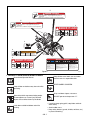
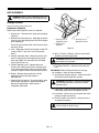
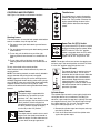
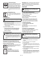
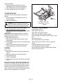
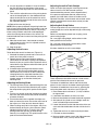
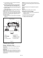
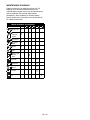
Promaster 250Z & 260Z
Owner/Operator Manual
Models
992018 - PM 260Z
992020 - PM 260Z
992021 - PM 260Z
992022 - PM 260Z
992023 - PM 250Z
992024 - PM 260Z
992027 - PM 260Z
ENGLISH
FRANÇAIS
ESPAÑOL
08486600A 10/00
Supersedes 08486600
Printed in USA
CONTROLS AND FEATURES
18
8
9
10 11 12
13
7
14
19
15
16
6
2
5
17
4
WARNING
3
The engine exhaust from this product
contains chemicals known to the State
of California to cause cancer, birth
21
defects or other reproductive harm.
20
1
22
OF1722
Figure 1
ENGLISH
1. Mower Deck with Chute Deflector
2. Fuel Shut Off Valve
3. Parking Brake
4. Battery
5. Hour Meter
6. Oil Pressure Indicator
7. Engine Frame and Hood (260Z)
8. Fuel Tanks and Caps
9. Choke Control
10. Throttle Lever
11. Ignition Switch
12. Power Take Off (PTO) Switch
13. Steering Levers
14. Mower Lift Lever
15. Seat Adjustment Lever
16. Seat Suspension Adjustment Knob
(260Z)
17. Height of Cut Indicator
18. Hydraulic Oil Reservoir
19. Engine Hood Latch (260Z)
20. Foot Board Latch
21. Cylinder Stop Storage Post
22. Cylinder Stops
WARNING
The engine exhaust from this product
contains chemicals known to the State
of California to cause cancer, birth
defects or other reproductive harm.
3
FRANÇAIS
ESPAÑOL
1. Carter de coupe avec déflecteur
2. Robinet de carburant
3. Frein de stationnement
4. Batterie
5. Compteur horaire
6. Indicateur de pression d'huile
7. Châssis du moteur et capot (260Z)
8. Réservoirs de carburant et bouchons
9. Starter
10. Manette des gaz
11. Contacteur de démarrage
12. Contacteur de régime de la PdF
13. Leviers de direction
14. Levier de relevage de la tondeuse
15. Levier de réglage du siège
16. Levier de réglage de la suspension
(260Z)
17. Indicateur de hauteur de coupe
18. Réservoir d’huile hydraulique
19. Verrou du capot du moteur (260Z)
20. Attache du repose-pied
21. Montant de remisage de butées de
vérin
22. Butées de vérin
1. Plataforma de corte
2. Válvula de cierre de combustible
3. Freno de estacionamiento
4. Batería
5. Horómetro
6. Indicador de la presión del aceite
7. Motor y cubierta del motor (260Z)
8. Tapas y depósitos de combustible
9. Control de aire
10. Palanca de ralentí
11. Interruptor de encendido
12. Interruptor de la toma de fuerza
(TDF)
13. Palancas de dirección
14. Palanca de elevación del
cortacésped
15. Palanca de ajuste del asiento
16. Palanca de ajuste de la suspensión
(260Z)
17. Altura del indicador de corte
18. Depósito de aceite hidráulico
19. Traba del capó del motor (260Z)
20. Traba de la plataforma de pie
21. Poste de almacenamiento del tope
del cilindro
22. Topes de cilindro
23. ZylinderanschlagAufbewahrungspfosten
24. Zylinderanschläge
4
TABLE OF CONTENTS
Controls and Features . . . . . . . . . . . . . . . . . . . . . .3
Maintenance . . . . . . . . . . . . . . . . . . . . . . . . . . . . . 15
Introduction. . . . . . . . . . . . . . . . . . . . . . . . . . . . . . .5
Attachments and Accessories . . . . . . . . . . . . . . 25
Safety. . . . . . . . . . . . . . . . . . . . . . . . . . . . . . . . . . . .6
Maintenance Schedule . . . . . . . . . . . . . . . . . . . . 23
Assembly. . . . . . . . . . . . . . . . . . . . . . . . . . . . . . . .11
Specifications. . . . . . . . . . . . . . . . . . . . . . . . . . . . 24
Operation. . . . . . . . . . . . . . . . . . . . . . . . . . . . . . . .12
Warranty . . . . . . . . . . . . . . . . . . Inside Back Cover
INTRODUCTION
THE MANUAL
PRODUCT REGISTRATION
Before operation of unit, carefully and completely read
your manuals. The contents will provide you with an
understanding of safety instructions and controls during
normal operation and maintenance.
All reference to left, right, front, or rear are given from
operator sitting in the operation position and facing the
direction of forward travel.
A warranty card must be filled out, signed, and returned
at time of purchase. This card activates the warranty.
Claims meeting requirements during limited warranty
period will be honored. Return your registration card to
assure warranty service.
Use only Gravely replacement parts. The replacement of
any part on this equipment with anything other than a
Gravely authorized replacement part may adversely
affect the performance, durability, and safety of this unit
and may void the warranty. Gravely disclaims liability for
any claims or damages, whether regarding warranty,
property damage, personal injury or death arising out of
the use of unauthorized replacement parts.
SERVICE AND
REPLACEMENT PARTS
Transfer
model & serial
number
label from
product
registration
here.
When ordering publications,
replacement parts, or making service
inquiries, know the Model and Serial
numbers of your unit and engine.
Numbers are located on the product
registration form in the unit literature
package. They are printed on a serial
number label, located on the frame of
your unit (Figure 2).
DISCLAIMER
Gravely reserves the right to discontinue, change, and
improve its products at any time without public notice or
obligation to the purchaser. The descriptions and
specifications contained in this manual were in effect at
printing. Equipment described within this manual may
be optional. Some illustrations may not be applicable to
your unit.
• Record Unit Model and Serial numbers here.
DEALER DELIVERY
• Record Engine Model and Serial numbers here.
Dealer should:
1. Test brakes (See Operation Section) after tractor is
assembled to be sure adjustment has not been
disturbed in shipment (See Adjustment Section).
Wheel brakes are properly adjusted at factory.
2. Check the safety interlock system to make sure that
it is functioning properly. With operator on seat, unit
must not start unless Speed Selector is in neutral
(N) and Implement Power disengaged (Off). Engine
must stop if operator leaves seat when Speed
Selector is in any drive position or with Implement
Power engaged (On). Refer to Adjustment Section.
3. Fill out Original Purchaser Registration Card and
return the card to Gravely.
4. Explain Gravely Limited Warranty Policy.
Serial Number Label
Figure 2
UNAUTHORIZED REPLACEMENT PARTS
OC0191
GB - 5
Copyright 2000
5. Explain recommended lubrication and maintenance.
Advise customer on adjustments.Instruct customer
on controls and operation of unit. Discuss and
emphasize the Safety Precautions.
Give customer Owner/Operator, Parts, and Engine
Manuals. Advise customer to thoroughly read and
understand them.
Customer Note: Your Dealer has been provided
complete setup and preparation instructions which must
be completed prior to you taking delivery of this unit. The
dealer is required to review important information in this
manual with you before or upon delivery of the unit or
attachment.
SAFETY
SAFETY ALERT SYMBOL
REQUIRED OPERATOR TRAINING
These are safety alert symbols. They
mean:
Original purchaser of this unit was instructed by the seller
on safe and proper operation. If unit is to be used by
someone other than original purchaser (loaned, rented or
sold), ALWAYS provide this manual and any needed
safety training before operation.
• ATTENTION!
OL1253
• YOUR SAFETY IS INVOLVED!
When you see this symbol:
SAFETY DECALS AND LOCATIONS
• BECOME ALERT!
ALWAYS replace missing or damaged Safety Decals.
Refer to Figure 3 for Safety Decal locations.
• OBEY THE MESSAGE!
OL3900
SIGNAL WORDS
The safety alert symbols above and signal words below
are used on decals and in this manual.
Read and understand all safety messages.
DANGER: IMMINENTLY HAZARDOUS
SITUATION! If not avoided, WILL RESULT in
death or serious injury.
WARNING: POTENTIALLY HAZARDOUS
SITUATION! If not avoided, COULD RESULT in
death or serious injury.
CAUTION: POTENTIALLY HAZARDOUS
SITUATION! If not avoided, MAY RESULT in
minor or moderate injury. It may also be used to
alert against unsafe practices.
NOTATIONS
NOTE: General reference information for proper operation and maintenance practices.
IMPORTANT: Specific procedures or information
required to prevent damage to unit or attachment.
PRACTICES AND LAWS
Practice usual and customary safe working precautions,
for the benefit of yourself and others. Understand and
follow all safety messages. Be alert to unsafe conditions
and the possibility of minor, moderate, or serious injury or
death. Learn applicable rules and laws in your area.
GB - 6
5
07735200C
DANGER / PELIGRO
• Avoid injury - Stay clear of rotating parts.
• Risque de blessures - ne pas s’approcher des pièces en
mouvement.
• Evitar lesiones - Mantenerse alejado de las piezas giratorias.
5
07735200C
DANGER / PELIGRO
• Avoid injury - Stay clear of rotating parts.
• Risque de blessures - ne pas s’approcher des pièces en
mouvement.
• Evitar lesiones - Mantenerse alejado de las piezas giratorias.
2
DANGER/PELIGRO
07731400D
4
3
WARNING/AVERTISSEMENT/ADVERTENCIA
Do not operate mower
unless guards are in
operating position or
bagger is attached.
07742300B
Ne jamais utiliser
la tondeuse sans
protecteur sur le
canal d'ejection ou
sans le bac monte.
No operar segadora a
menos que las defensas
esten en posicion de
operacion o el
recogedor este fijo.
1
2
DANGER / PELIGRO
DANGER/PELIGRO
17
TO AVOID SERIOUS INJURY OR DEATH
• Read the operator's manual.
• Keep children and others away from unit while
operating.
• Never direct discharge toward other people.
Thrown objects can cause injury.
• Look down and behind before and while backing.
• Never carry children.
• Go up and down slopes, not across.
• If machine stops going uphill, stop blade and
back down slowly.
• Avoid sudden turns.
• Keep safety devices (guards, shields, switches,
etc.) in place and working.
• Check interlock system per manual before use.
• Understand location and function of all controls.
• Never allow operation by untrained persons.
07731400D
POUR EVITER LES BLESSURES GRAVES OU LA MORT
• Lire le manuel d'utilisation.
• Éloigner les engants et tout autre personne pendant le fonctionnement de la
machine.
• Ne jamais décharger directement en direction de quelqu’un. Des particules
projetées peuvent provoquer des blessures.
• Regardez derriere et sur les cotes lorsque vous reculez.
• Ne transportez jamais dénfant.
• Tondez toujours de haut en bas et inversement jamais le long des pentes.
• Si la machine sárrete en montee. Debrayez la lame et redescendez
doucement.
• Evitez les virages brusques.
• Maintenez toujours en place tous les elements de securite (protecteurs,
interrupteurs, etc.).
• Controlez le bon fonctionnement des interrupteurs de securité avant
utilisation tel q'uindiqué dans le manuel d'utilisation.
• Comprenez bien la fonction et la situation de chacun des leviers et boutons
de commande.
• Never allow operation by untrained persons.
MAX
PARA EVITAR DAÑOS SERIOS O LA MUERTE
• Leer el manual del operador.
• Mantenga la unidad alejada de los niños u otras personas
cuando esté en funcionamiento.
• Nunca dirija la descarga hacia otras personas, ya que los
objetos lanzados pueden provocar lesiones.
• Antes y durante retroceso mirar hacia abajo y detras.
• Nunca monten niños.
• Suba y baje pendientes, no transversalmente.
• Si la maquina se detiene subiendo cuesta, desactive la
cuchilla y baje lentamente.
• Evite viradas subitas.
• Mantenga artefactos de seguridad (defensas, protectores,
interruptores, etc.) en su lugar y trabajando.
• Verifique en el manual el sistema de engranar antes de usar.
• Tenga conocimiento de funciones y localizaciones de todos
los controles.
• Never allow operation by untrained persons.
07734700D
Figure 3
OF1624
1. DANGER! TO AVOID SERIOUS INJURY OR DEATH
Keep children out of work area and under
watchful care of a responsible adult.
Read Owner/Operator Manual.
OL4470
OL1801
NEVER CARRY CHILDREN.
Keep children and others away from unit while
operating.
OL4480
OL4370
Go up and down slopes, not across.
DO NOT operate on slopes over 17˚.
Never direct discharge toward other people.
Thrown objects can cause injury. Remove
objects that could be thrown by the blade.
MAX
17°
OL4450
OL0910
• If machine stops going uphill, stop blade and back
down slowly.
• Avoid sudden turns.
• Keep safety devices (guards, shields, switches, etc.)
in place and working.
Look down and behind before and while
backing.
OL4460
GB - 7
UNIT SAFETY
• Check interlock system per manual before use.
• Understand location and function of all controls.
• Never allow operation by untrained persons.
Rules of Operation
KNOW your Unit – before starting engine. Understand:
• How to operate all controls
• The functions of all controls
• How to STOP in an Emergency
• Speed ranges
2. DANGER! ROTATING PARTS
Always keep feet and hands away from
rotating parts.
Walk Around Inspection
Complete a walk around inspection of unit and work area
to understand:
• Work area
• Your unit
• All safety decals
OL3030
Always stand clear of discharge area. Do not
direct discharge toward other people.
OL0910
Safety Interlock System
Keep people away from unit while operating.
Check Safety Interlock System for proper operation daily
(see Operation section).
Clearances
OL3292
Shut off engine, remove key, read manual
before you adjust or repair unit.
ALWAYS check overhead and side clearances carefully
before operation.
ALWAYS be aware of traffic when operating along streets
or curbs. Set up safety signs and/or flags.
NO STEP! Always keep feet away from
rotating parts.
PERSONAL SAFETY
OL4010
Responsible Operators
OL4420
3. WARNING! Do not operate mower unless guards are
in operating position or bagger is attached.
Always stand clear of discharge area.
•
•
•
•
Only trained adults may operate unit.
Training includes actual operation.
Clearly understand instructions.
Be alert! Conditions can change.
Pre-Start
Before starting engine: disengage PTO and set parking
brake.
OL4430
Do not operate mower unless bagger is
attached or guards are in operating position.
Hot Surfaces
DO NOT touch parts which are hot. Allow parts to cool.
Safety Covers
OL3320
4. HOT SURFACES!
DO NOT touch parts which are hot from
operation. ALWAYS allow parts to cool.
OS0731
5. DANGER!
AVOID INJURY. Stay clear of rotating parts.
ALWAYS keep discharge cover or complete grass bagger
in place.
Replacement Parts
ALWAYS maintain unit in safe operating condition.
Damaged or worn out muffler can cause fire or explosion.
Clear Area
ALWAYS clear area before operation. Thrown objects can
cause injury.
Speed Ranges
DO NOT mow at too fast a rate. DO NOT change engine
governor settings or over speed the engine.
OL4730
Avoid loss of control
Avoid uneven work areas and any rough terrain.
GB - 8
Thrown Objects
Hazardous Slopes
Disengage PTO when crossing hard surfaces and gravel
drives. Be aware of mower discharge direction and do not
point it at anyone.
Keep all safety covers:
• In place
• In proper working condition
Operate up and down slopes, not across slopes.
DO NOT operate on slopes of more than 17°. Keep all
movement on slopes slow and gradual. DO NOT make
sudden changes in speed or direction. Use a slow speed
to avoid stops or shifts on slopes. Avoid starting or
stopping on a slope. Use of a Roll Over Protection
System (ROPS) is recommended for slope operation.
See Attachments and Accessories.
Safety Gear
Wear adequate safety gear, protective gloves and
footwear. NEVER wear loose clothing, jewelry or long
hair that may get caught in rotating parts.
Protect eyes, face and head from objects that may be
thrown from unit.
Operation
OPERATIONAL SAFETY
Only trained adults may operate unit. Training includes
actual operation
Safe Distances
Visibility
Keep children and people away from unit during
operation. Use care when approaching blind corners,
shrubs, trees or other objects that may obscure vision.
ALWAYS keep feet and hands away from all rotating
blades. Rotating parts can cut off body parts.
ALWAYS operate unit when there is good visibility and
light.
Roll-Away
DO NOT leave unit unattended on a slope. ALWAYS set
park brake when leaving unit.
NO Drugs
NEVER operate unit after or during the consumption of
medication, drugs or alcohol. Safe operation requires
your complete and unimpaired attention at all times.
Starting
Start and operate unit only when seated in operator’s
position. Steering control levers must be in neutral, PTO
disengaged and parking brake set when starting engine.
Tip over
Stay away from moving parts. Keep safety devices or
guards in place and functioning properly. NEVER modify
or remove safety devices.
Enclosed areas
Reverse
ALWAYS backup slowly. ALWAYS look down and behind
before and while backing. Do not operate in reverse
unless absolutely necessary.
Load Capacity
Use care when pulling loads. Use only approved drawbar
hitch points. Limit loads to those you can safely control.
If tires lose traction, turn off PTO and proceed slowly
straight down slope. If you cannot back up the slope or
feel uneasy, do not mow it. Avoid mowing wet grass.
Parking Brake
Check brake operation frequently. Adjust and service as
required.
NEVER allow anyone to operate this unit when their
alertness or coordination is impaired.
Avoid Entanglement
Avoid uneven, unstable and rough terrain. DO NOT
operate near drop offs, ditches, or embankments. Unit
can suddenly turn over if a wheel is over the edge of a
cliff or ditch, or if an edge caves in.
Traction
NO Alcohol
DO NOT run engine in an enclosed area. Always provide
good ventilation.
Explosive Fuel
Fuel is highly flammable and its vapors can explode. Use
ONLY approved RED fuel containers.
NO Smoking!
NO Sparks!
NO Flames!
Allow engine to cool before servicing.
NEVER fill fuel tank when engine is running, hot or unit is
indoors.
Avoid Sharp Edges
No Riders
Moving parts can cut or amputate fingers or a hand.
Wrap blade(s) or wear gloves to service. Rotating one
blade will cause other blades to rotate.
Never carry passengers.
Avoid Pinch Points
ALWAYS keep hands away from all pinch points.
GB - 9
Abnormal Vibrations
Disengage PTO, stop engine, remove key and wait for all
moving parts to stop before servicing or unclogging
mower.
ALWAYS shut off engine, remove key and lower the
mower to prevent unauthorized use before leaving unit.
Parking
NEVER leave a running unit unattended. ALWAYS turn
off PTO, lower throttle setting, set parking brake, and stop
engine.
PTO Operation
Turn off power to attachment when crossing drives, etc.
ALWAYS turn off PTO, shut off engine, remove key and
wait for moving parts to stop before leaving operators
position.
MAINTENANCE, SERVICE AND STORAGE
SAFETY
When opening engine cover, use care to properly engage
cover prop into its retaining slot. Be sure footing is secure
to accomodate weight shift of hood when rotating to full
service position.
Hardware
Keep nuts and bolts, especially blade attachment bolts,
tight and keep equipment in safe operating condition.
Inspect blades before use for excess wear or damage.
Keep hardware, especially blade attachment bolts, tight.
Stop Engine
Before maintenance, adjustments or service (except
where specifically recommended) shut off engine and
remove ignition key.
Cool Engine
Allow hot parts to cool.
Cleaning
Storage
DO NOT store unit with fuel in the fuel tank inside a
building where any ignition sources are present. Allow
unit to cool completely. Shut off fuel valve.
ALWAYS clean unit before extended storage. See engine
manual for proper storage.
Battery
Battery posts, terminals and related accessories contain
lead and lead compounds, chemicals known to the State
of California to cause cancer and reproductive harm.
Wash hands after handling.
Avoid Electric Shock. DO NOT reverse battery
connections.
Explosive Gases! Poisonous battery fluid contains
sulfuric acid and its contact with skin, eyes, or clothing
can cause severe burns.
No flames, No sparks, No smoking near battery. ALWAYS
wear safety glasses and protective gear near battery.
DO NOT TIP battery beyond a 45° angle in any direction.
ALWAYS KEEP BATTERIES OUT OF REACH of
children.
Keep unit free of grass, leaves or other debris. Clean up
oil or fuel spills.
Lower cutting deck when unit is parked or stored unless a
positive mechanical lock is used.
Replacement Parts
Keep all parts in good working condition. Replace worn
or damaged parts only with Gravely recommended
service parts.
Attachment and Accessory Safety
Use only attachments or accessories designed for your
unit.
Spark Arrester
This product is equipped with an internal combustion
engine. DO NOT use on or near any unimproved, forest
covered or brush covered land unless the exhaust
system is equipped with a spark arrester meeting
applicable local, state or federal laws. A spark arrester, if
used, must be maintained in effective working order by
the operator.
Transport
Use extra care when loading or unloading unit onto trailer
or truck. Secure unit chassis to transport vehicle. NEVER
secure from rods or linkages that could be damaged.
DO NOT transport with attachment in raised position.
Shut off fuel valve during transport.
Service Position
ALWAYS block wheels and know all jack stands are
strong and secure and will hold weight of unit during
maintenance.
GB - 10
ASSEMBLY
UNIT ASSEMBLY
WARNING: Make all seat adjustments with unit
stationary, parking brake on and engine shut off.
2
Package Contents:
2
Unit, Mower Deck and Literature Pack
1
3
Preparation Checklist
Refer to the Owner/Operator manual as required.
1. Unpack Unit - Remove shrink wrap and packaging
materials.
2. Remove Unit From Container - Open Bypass Valves
(dump valves) (See Moving the Unit with the Engine
Off in Operation).
Push unit from container onto a level surface. Close
the dump valves.
3. Tires - Adjust tire pressure for front tires; 20-25 PSI
(138-172 kN/m2), rear tires; 12-15 PSI (83-103
kN/m2).
4. Position and Attach Seat - Remove nuts from seat
studs in hood frame. Peel off paper backing from
foam tape (260Z). Lift and rotate seat onto hood
frame. Secure with nuts.
5. Position Steering Levers - Remove bolts and
spacers from steering rod. Flip the steering levers
up into operating position. Reinstall spacers, bolts
and nuts. Tighten hardware securely. See Figure 4.
6. Battery - Remove battery from unit, fill with
electrolyte and charge (See Battery in
Maintenance).
7. Check Engine Crankcase - To access engine, open
hood. Check and add oil if needed. See Engine
Manual for specifications. After service is
completed, close hood.
OF3140
1. Steering Lever in
Shipping Position
2. Spacers and
Hardware
3. Steering Lever in
Operation Position
Figure 4
8. 60" & 72" Decks - Remove, reverse, and reinstall
deflector and mounting bracket.
WARNING: Deflector must pivot freely. DO NOT
over tighten the pivot bolts.
9. Fill Engine Fuel Tank - Add clean fuel to the fuel
tank.
IMPORTANT: Refer to Engine Manual for fuel type.
10. Hardware - Check for loose hardware.
11. Check Safety Interlock System - Check to see that
the interlock system operates correctly.
WARNING: FAILURE OF INTERLOCK together
with improper operation can result in severe
personal injury.
12. Lubrication - Lubricate all fittings per maintenance
label under hood and check hydrostat oil level.
13. Level Deck - Check unit to assure deck level set at
factory has been maintained.
14. Check Function of all Controls - Ensure unit runs
and performs properly.
WARNING: FAILURE OF CONTROLS could
result in death or serious injury.
GB - 11
OPERATION
CONTROLS AND FEATURES
FAST
See Figure 1 for Controls and Features locations.
A
B
C
D
Throttle Lever
The throttle lever is used to change the
speed of the engine. Moving the throttle
lever to the “Fast” position increases the
engine speed. Moving the lever to the
“Slow” position decreases the engine
speed.
077348A
Steering Levers
SLOW
The control levers are used for both speed and direction
control. In addition, they will stop the unit.
A. For reverse travel, pull both steering control levers
backward.
B. For straight forward travel, push both steering control
levers forward.
C. To turn left, pull the left back or push the right
Steering Control Lever forward or a combination of
both.
D. To turn right, pull the right back or push the left
Steering Control Lever forward or a combination of
both.
To stop, return both to the neutral position.
When released, levers should automatically return to
neutral position.
NOTE: The steering controls are mechanically locked in
neutral whenever the parking brake is engaged.
NOTE: Aggressive turning can scuff or damage lawns.
ALWAYS keep both wheels rotating when making sharp
turns. DO NOT make turns with inside wheel completely
stopped. To obtain minimum turning radius, slowly
reverse inside wheel while moving outside wheel slowly
forward.
OFF
RUN
START
OF1750
Ignition Switch
The ignition switch is operated with a
removable key. The switch has three
positions: “Off”, “Run” and “Start”.
To start the engine, the key must be in the
“Start” position. Once the engine has
started release the key and it will return to
the “Run” position. To stop the engine,
turn the key to the “Off” position.
Choke Control
OF1680
The choke control is used to start a cold
engine. Push the choke lever forward to
choke the engine. Pull the choke lever to
the rear when the engine gets warm.
OF1700
Power Take Off (PTO) Switch
ON
OFF
OE0261
The power take off (PTO) switch is used to
engage and disengage the mower. When
the PTO switch is in the “On” position,
mower is engaged; when the PTO switch
is in the “Off” position, mower is disengaged. Pull for “On” and push for “Off”.
NOTE: The engine will not start unless the steering control levers are in the neutral position and the PTO switch
is in the “Off” position and parking brake is set.
Mower Lift Lever
The mower lift lever is used to raise and
lower the mower deck. The lift lever is
located on the left side of tractor. Move the
lever rearward to raise, and forward to
lower the deck. Release lever to hold in
selected position. The approximate
mowing height in inches is shown on the
indicator located on the lift cylinder near
operator’s right foot.
OF1700
Cylinder Stops
The cylinder stops ensure the same cutting height after
raising the deck to clear an obstacle. The stops are
stored on a post under the operator’s right leg. The stops
are supplied in two (2) sizes. The thinner stops change
the cutting height by 1/4" (.64 cm). The thicker stops
change the cutting height by 1/2" (1.27 cm).
1. Remove the cylinder stops from the post and snap
onto the lift cylinder rod.
2. Push the lift lever forward until the cylinder rests
against the cylinder stops.
GB - 12
Fuel Shut-Off Valve
OF1880
This valve is used to control the flow of
fuel leaving the fuel tanks. The valve
must be open for the engine to operate.
It should be turned to "OFF" if the unit
is to be stored for extended periods. It
is also used to select which fuel tank
the engine will draw fuel from, right or
left.
IMPORTANT: Keep a record of Hour Meter readings for
recommended Lubrication and Maintenance intervals.
NOTE: For accurate readings be sure Ignition Switch is
OFF when tractor is not in operation.
PRE-START
CAUTION: Make sure all hardware is tight, all
safety devices in place and all adjustments
made correctly.
Parking Brake Lever
1. Check Safety Interlock System
1. Pull lever up to engage parking brake.
2.Push lever down to disengage parking
brake.
If this system does not function as described do not
operate until repairs are made.
OF1740
2. Check Air Cleaner
Check air filter for dirt. Clean as required. See
Maintenance Section.
Seat Adjustments
WARNING: Make all seat adjustments with unit
stationary, parking brake on and engine shut off.
3. Check Engine Fuel and Crankcase Oil
Check and add fuel if required. Check that engine
crankcase oil is full. Refer to Maintenance Section.
To adjust seat forward or backward:
1. While seated, pull seat adjustment lever outward and
slide seat into desired position.
2. Release lever and slide seat forward or back to lock
seat into position.
To adjust seat suspension (260Z):
• To make seat more firm turn knob clockwise. To
make seat less firm turn knob counter clockwise.
Turn knob several turns at a time until desired
position is achieved.
Be sure all controls can be reached safely from
operator’s position.
Safety Interlock System
STARTING AND SHUT OFF
WARNING: Safety interlock system failure and
improper operation of unit can result in death or
serious injury. Test this system each time the
unit is operated. If this system does not function
as described, do not operate until repairs are
made.
Engine must shut off if the operator attempts to leave the
seat with the transmission engaged, parking brake
disengaged or PTO engaged. Engine must not start
unless PTO is disengaged and parking brake is engaged.
Engine Oil Pressure Indicator
This will light up “Red” if the oil pressure is
low. Check oil level and add if necessary.
Refer to engine manual.
OG0601
Hour Meter
Hour Meter operates when Ignition
Switch is in the “Run” position and
records actual time engine operates.
4. Check Tire Pressure
5. Check Hydraulic Fluid Level
6. Adjust Seat
STOPPING IN AN EMERGENCY
The unit can be stopped immediately at any time by
turning the ignition key to the "Off" position.
CAUTION: Read entire Owner/Operator
Manual, Clutch Manual, and Engine Manual
first.
DO NOT attempt to start engine at this time.
To start the engine:
1. Make sure the control levers are in the neutral
position.
2. Put the PTO switch in the “Off” position.
3. Set Parking Brake.
4. If the engine is cold, move the choke control to the
“On” position. If the engine is warm or hot, do not use
choke.
5. Move the throttle to 3/4 “Fast” position. See Engine
Manual for detailed instructions.
6. Put the ignition key in the switch and turn it to the
“Start” position.
7. As soon as the engine starts, release the key and
move the choke control to the “Off” position from the
“Choke” position. Wait until the engine is running
smoothly before operation.
GB - 13
To stop the engine:
1. Bring the steering control levers to neutral.
Disengage the PTO and set the parking brake.
2. Move the throttle lever to the “Slow” position.
3. Turn the ignition key to the “Off” position.
2
1
TO MOW WITH UNIT
Operate the unit only when seated in the operator’s
position.
1. Start the engine. Let the engine warm until it is
running smoothly.
2. Release parking brake.
Front of unit
1. Left Bypass Valve Lever
2. Right Bypass Valve Lever
WARNING: Move the steering control levers
slowly and keep the throttle control lever at slow
speed until you learn how to operate the unit.
3. Move the control levers to the neutral position.
4. Slow the engine down to about 3/4 speed.
5. Move the PTO switch to the “On” position to engage
the mower.
IMPORTANT: Never engage the PTO if the mower is
plugged with grass or other material. This may cause
damage to the electric clutch.
6. Move throttle control to fast.
7. Move the control levers forward to obtain a slow
ground speed.
8. To disengage the mower, move the PTO switch to the
“Off” position.
9. When you know how to operate the unit, select a
speed appropriate to your mowing conditions.
PARKING
Figure 5
OF1730
FOR BEST PERFORMANCE
Cut grass when it is dry.
Keep mower blades sharp.
Keep mower deck properly leveled.
Adjust anti-scalp rollers to prevent scalping.
Do not set height of cut too low. For very tall grass, mow
twice.
Do not travel too fast.
Mow with the engine set at full throttle.
When mulching, only remove 1/3 of grass length per
cutting.
Discharge clippings into areas already cut.
Vary cutting pattern with each mowing.
Do not allow grass or debris to collect inside of mower
deck. Clean after each use.
To park the unit:
1. Move the control levers to the neutral position. Turn
off PTO.
2. Move the throttle lever to the “Slow” position.
3. Set the parking brake.
4. Lower the attachment.
5. Turn the ignition key to the “Off” position and remove
the key.
MOVING THE UNIT WITH THE ENGINE OFF
To move the unit without the engine running, rotate the
bypass valve (dump valve) levers located on the pumps
toward the center of the tractor approximately 1/2 turn
using a wrench. Levers must be returned to their original
position in order to operate the unit. (Figure 5)
GB - 14
MAINTENANCE
Gravely Dealers will provide any service which may be
required to keep your unit operating at peak efficiency.
Should engine service be required, it can be obtained
from a Gravely Dealer or the engine manufacturer’s
authorized service center.
7
WARNING: MOVING PARTS can result in
serious injury or death.
ALWAYS stop unit, remove key, and wait for
moving parts to stop before attempting any
maintenance procedures.
ELECTRIC SHOCK can result in serious injury
or death and/or damage to equipment.
DO NOT remove wire from spark plug while
engine is running.
8
4
1
5
2
9
3
10
CAUTION: HOT SURFACES may result in
injury. DO NOT touch engine or drive parts
which are hot from operation. Allow parts to cool
before servicing.
SERVICE POSITIONS
6
Service position for 260Z:
1. Place unit on a flat level surface. ALWAYS stop
engine. Assure unit is secure and will not tip over.
Strap and clamp onto lift if used.
2. Place steering levers in neutral position and set
parking brake.
3. Unhook hood latches.
4. Firmly grasp engine frame and cover. Lift to desired
service position. (Figure 6)
1.
2.
3.
4.
5.
6.
7. Daily Service Position
8. Full Service Position
9. Engine
10. No Step Decal
11. Battery
OF1811
FILLING FUEL TANK
WARNING: EXPLOSIVE VAPORS and
FLAMMABLE FUEL can result in serious injury
or death. Handle fuel with care. ALWAYS use an
approved (RED) fuel container.
No Smoking!
No Lighted Materials!
No Open Flame!
Allow engine to cool.
Use caution with fuel. Fuel is very flammable.
Keep fuel in a clean and tight container. Keep
fuel away from fire or heat. Never put fuel in the
fuel tank while the engine is running or hot.
Clean up any spilled fuel before starting the
engine.
Daily Service Position: Place engine hood prop rod into
service slot. Assure rod is engaged in slot properly.
Full Service Position: Slowly release frame after seat
contacts foot board. Use care and be sure of your footing.
Do not step on mower deck.
5. When service is complete, lower hood and secure
with latches.
Remove pin holding seat down on left rear corner. Firmly
grasp seat frame handle and lift past vertical. Lay
inverted seat on foot rest. When service is complete,
return seat to upright position and reinstall pin.
Steering Levers
Parking Brake
Footboard
Engine Hood & Frame
Engine Hood Prop Rod
Service Slot
Figure 6
CAUTION: WHEN OPENING ENGINE COVER,
USE CARE TO PROPERLY ENGAGE PROP
INTO SLOT. Be sure footing is secure to
accomodate weight shift of hood when rotating
to full service position.
Service Position for 250Z
11
Add fuel to Fuel Tank as needed. See your Engine
Manual for correct type and grade of fuel.
To add fuel to the fuel tank:
1. Refuel the unit only in a well ventilated open area.
2. Stop the engine.
GB - 15
3. Clean the fuel cap and the area around the fuel cap
to prevent dirt from entering the fuel tank. Remove
the cap from the fuel tank.
4. Fill the fuel tank. Be careful not to spill the fuel. Do
not overfill, allow for fuel expansion. Stop filling when
fuel is about 1" below the bottom of the neck.
5. Install the cap on the fuel tanks and tighten.
6. Clean up any spilled fuel before starting the engine.
1
5
2
ENGINE
Correct maintenance can increase the life of the engine.
See your engine manual for information on the operation
and maintenance of your engine.
1. Before each use, check the level of the oil in the
engine. Never operate the engine when the oil level is
below the add mark.
2. Each day before operating, check the air cleaner
element. Dirt can decrease the flow of air to the
engine.
3. Each day before operating, check the air cooling
system on the engine. Debris can decrease the flow
of air cooling the engine.
4. Follow the maintenance instructions in your engine
manual concerning oil changes and engine coolant
changes.
BELTS
WARNING: MOVING PARTS can cut or
amputate body parts. ALWAYS wait for moving
parts to stop before performing maintenance or
service.
CAUTION: DAMAGED OR WORN BELTS may
result in injury and/or damage to unit. Check
belts for excessive wear or cracks often.
Belt Access
1. Properly stop and park unit (refer to Operation
Section).
2. Lower the mower.
3. Place seat in most reward position.
4. Remove belt covers.
5. Place foot board in open position (Figure 7).
6. Secure raised footboard with latch.
4
3
1. Footboard in open
position
2. Footboard in closed
position
3. Support Frame
4. Pivot
5. Latch
Figure 7
OF1802
Replacing Mower Belts
NOTE: Long belt must be removed to remove short belt.
1. Roll long belt off left blade spindle and remove from
deck.
2. Roll short belt off right blade spindle and remove
from deck. Idler pivot bolt must be loosened slightly
to gain clearance to remove belt from under idler
pulley (Figure 8).
CAUTION: Use care when releasing idler spring
tension. Keep body parts well away from idlers
when performing this operation.
3. Arrange new mower belt(s) on deck (short belt first).
Retighten short belt idler pivot bolt. Install belts on
sheaves. Roll belts onto blade sheave last.
4. Replace belt covers and return foot board to closed
position.
Replacing the Hydro Pump Belt
1. Properly stop and park unit (refer to Operation
Section).
2. Remove the mower belt from the mower clutch
sheave. See “Replacing Mower Belts”.
3. Remove old hydro pump belt by rolling belt off right
hand hydrostat sheave first (Figure 9).
4. Install new pump belt by positioning belt on sheaves.
Roll belt onto right hand hydrostat sheave last.
5. Put the mower belt back on mower clutch sheave.
See “Replacing Mower Belts”.
GB - 16
TIRES
Before each use make a visual check of tires. The correct
6
5
2
air pressure is 12-15 psi (83-103 kN/m ) for the rear tires
1
2
and 20-25 psi (138-172 kN/m ) for the front tires.
2
LUBRICATION
3
4
1.
2.
3.
4.
5. Right Hand Hydrostat
6. Left Hand Hydrostat
Hydro Belt
Spring
Idler
Engine Sheave
Figure 8
OF1631
3
2
IMPORTANT: Wipe each fitting clean before and after
lubrication.
Steering system and Speed Selector components should
be lubricated every 50 hours of operation or every
3 months whichever comes first. (Figure 10)
Lube fitting locations are:
– each deck push arm (2)
– Hydro Idler (1)
– front axle pivot (1)
Apply Stens Mix Hi-Temp Grease or equivalent to the
lube fittings. Order P/N: 00036700 - ten pack of 14 oz.
cartridges.
When using Stens Mix Grease for the first time, all
components should be thoroughly cleaned prior to
lubricating.
Apply oil at all pivot points and pin connections.
4
1
2
4
3
1
5
2
4
OF1791
50" and 60" Belt Layout
1.
2.
3.
4.
5.
REF
Long Mower Belt
Short Mower Belt
Springs
Idlers
Mower Clutch Sheave
Figure 9
LUBRICATION
QTY DESCRIPTION-LOCAT
ION
INTERVAL
REF
1
GREASE
1
HYDRO IDLER
50 Hrs.
1
2
REPACK
2
CASTER PIVOT
400 Hrs
2
3
GREASE
1
AXLE PIVOT
50 Hrs
3
4
GREASE
2
PUSH ARM PIVOT
50 Hrs
4
ALL PIVOT POINTS,
PIN CONNECTIONS
50 Hrs
OIL
OF1641
Figure 10
FASTENERS
Before each use, check mower blade mounting hardware
and all other fasteners. Replace fasteners that are
missing or damaged. Tighten all nuts and bolts to their
correct torque value.
GB - 17
HYDRAULICS AND TRANSAXLES
MOWER BLADES
WARNING: HYDRAULIC FLUID can result in
severe burns. Fluid in hydraulic system can
penetrate skin and result in serious injury or
death.
Be sure to stop the engine before doing any
work on hydraulic parts.
Keep body and hands away from pin holes or
nozzles which expel hydraulic fluid when under
pressure. Use paper or cardboard, not hands, to
search for leaks.
Insure all hydraulic fluid connections are tight
and all hydraulic hoses and lines are in good
condition before applying pressure to system.
FOREIGN FLUID INJECTED INTO BODY can
result in gangrene. Fluid must be surgically
removed within a few hours by a doctor familiar
with this form of injury.
NOTE: If mower is used under sandy soil conditions,
replace blades when air lifts become eroded through at
ends (Figure 11).
1
2
3
4
1. Cutting Blade
2. Square Corner
Checking the Hydraulic Fluid Level
3. Air Lift Erosion
4. Air Lift
Figure 11
A check of the hydraulic fluid level should be made daily.
NOTE: The oil level can be checked with dipstick check.
To Check: first remove any dirt that may be around the
cap on the tank.
The oil level should be between two marks on dipstick.
Centered between the marks is best.
Add oil through the dipstick tube as needed. Do not
overfill.
Changing Hydraulic Fluid
The hydraulic oil filter and hydraulic oil should be
changed after the first 500 hours. Use Mobil 15W50
synthetic oil for best component life.
1. Clean around dipstick cap and dipstick. Remove
dipstick.
2. Place container under oil filter to catch oil.
3. Remove oil filter.
4. Allow tank to drain.
5. Install new oil filter.
6. Add new oil to the oil tank. It will take about 5 quarts.
Use Mobil 15W50 synthetic oil for best pump and
wheel motor life.
7. Properly dispose of waste oil.
OT0791
Sharpen the Mower Blades
CAUTION: Use sturdy gloves or padding to
protect hands when working with mower blades.
1. Turn the engine off. Remove the ignition key. Remove
the ignition wire from the spark plugs.
2. Remove the bolts, lock washer, the flat washers, and
the blades from the spindle shafts.
3. Sharpen the beveled edges of the blades in a straight
line. Do not change the angle of the beveled edge. If
more than 0.5 inches (12.7mm) are removed from
the width of a blade, discard the blade. Make sure the
sharpened blades are balanced. Balance must be
held within 1.3 inch ounces.
4. Put the blades, the flat washers, lock washers, and
the bolts back on the spindle shafts.
5. Tighten the bolts to a torque of 70 ft. lbs.
6. Put the ignition wires back on the spark plugs.
BATTERY
When charging battery remove it from unit first. Keep
batteries out of reach of children. ALWAYS follow
information provided on battery by the battery
manufacturer. Lead acid batteries generate explosive
gases. Severe chemical burns can result from improper
handling of battery electrolyte. Wear safety glasses and
proper protective gear when handling batteries to prevent
electrolyte from coming in contact with eyes, skin or
clothing.
GB - 18
After cleaning, apply a thin coat of grease or petroleum
jelly to terminals and cable ends to retard corrosion.
Reinstall battery.
WARNING: ELECTRIC SHOCK may result in
injury and/or damage to unit.
DO NOT allow tools or other objects to come
into contact with both terminals at same time.
ALWAYS remove Negative (–) Cable first to
reduce risk of sparks when removing Battery.
ALWAYS connect Positive (+) Cable first, then
connect Negative (–) Cable when installing
battery.
Electrolyte Level
WARNING: EXPLOSIVE GASES can result in
serious injury or death. ALWAYS keep open
flames, sparks, or smoking materials away from
Battery.
POISONOUS BATTERY FLUID contains
sulfuric acid and its contact with skin, eyes or
clothing can cause severe chemical burns.
ALWAYS wear safety glasses and protective
gear near battery.
DO NOT TIP any battery beyond 45º angle in
any direction.
ALWAYS KEEP BATTERIES OUT OF REACH
of children.
Every 25 hours of operation check electrolyte level of
each cell by removing caps one at a time. The electrolyte
level should be at level indicated. Use distilled water to fill
each cell if needed. Install and tighten each cap after
checking.
IMPORTANT: When distilled water is added to battery
during freezing weather, battery must be charged to mix
water with electrolyte, or water will remain at top and
freeze.
Battery Charger
Under normal conditions the engine alternator will have
no problem keeping battery charged. When unit has set
for an extended period of time without operation and the
battery has been completely discharged, a battery
charger will be required for recharging.
Before using a charger, an attempt can be made to
recharge the battery using the engine alternator by jump
starting the unit and allowing the engine to run.
Charging
WARNING: FROZEN BATTERIES CAN
EXPLODE and result in death or serious injury.
DO NOT charge a frozen battery. Let the battery
thaw out before putting on a charger.
WARNING: REVERSE CONNECTIONS may
result in sparks which may result in injury.
ALWAYS connect/disconnect cables in proper
order.
WARNING: Battery posts, terminals and related
accessories contain lead and lead compounds,
chemicals known to the State of California to
cause cancer and reproductive harm. Wash
hands after handling.
Battery Electrolyte First Aid
• External Contact: Flush with water.
• Eyes: Flush with water for at least 15 minutes and get
medical attention immediately!
• Internal Contact: Drink large quantities of water.
Follow with Milk of Magnesia, beaten egg or vegetable
oil. Get medical attention immediately!
IMPORTANT: In case of internal contact, DO NOT
induce vomiting!
Terminals
Keep battery and its terminals clean. Inspect monthly to
maintain best performance. To clean terminals, remove
battery from unit by removing cables.
Remove tie down rod nuts and lift battery out. Clean or
service battery away from unit. Remove corrosion from
battery terminals and cable connections with wire brush,
then wash with a weak baking soda solution.
IMPORTANT: DO NOT fast charge. Charging at a higher
rate will damage or destroy battery.
ALWAYS follow information provided on battery by
battery manufacturer. Contact battery manufacturer for
extensive instructions to charge battery.
1. Put unit into service position to gain access to
battery.
2. Disconnect negative (–) cable first, then positive (+)
cable (Figure 12).
3. Remove hold down and remove battery.
4. Place Battery on bench or other well ventilated place
where electrolyte spill will not create damage.
5. Initial Battery Setup - Remove caps and fill each
cell to level indicated with electrolyte at 1.230±
specific gravity and 80°F (27°C).
• Let battery stand for one half hour.
• Check electrolyte level and add more if necessary.
6. Connect positive (+) lead of charger to positive (+)
terminal, and negative (–) lead to negative (–)
terminal.
7. Charge the battery at two and a half amps for ten
hours or until all cells are gassing freely and the
specific gravity is constant over three 30 minute
intervals.
GB - 19
8. Immediately after charging, check electrolyte level. If
low, add distilled water to bring cell up to required
level.
9. Replace caps finger tight, wash off and dry battery.
10. Reinstall battery into unit and connect positive (+)
cable first, then negative (–) cable.
ADJUSTMENTS
Steering Control Neutral Adjustment
If the unit has excessive creep when the control levers
are in neutral, adjust as follows. (Figure 13)
2
1
2
1
3
2
4
3
1. Positive terminal
2. Negative terminal
Figure 12
3. Battery
5
4
OF1670
6
3
7
1.
2.
3.
4.
Jump Starting
The unit used for jump starting should have a 12 volt
battery with at least 500 cold cranking amperes, and a
negatively grounded system.
1. Ensure battery is not frozen. If the fluid is frozen,
remove battery from unit and allow it to thaw before
charging.
2. Connect the positive (+) jumper cable to the positive
terminal of the discharged battery.
3. Connect the other end of the same jumper cable to
the positive (+) terminal of the booster battery.
4. Connect one end of the second jumper cable to the
negative (–) terminal of the booster battery.
5. Make the final jumper cable connection to the engine
block or the furthest ground point away from the
discharged battery.
WARNING: Make sure cables are clear of any
moving engine parts before starting engine.
6. Start engine (refer to Operation Section). If engine
will not start after several tries, unit or battery may
need service.
7. After engine starts, leave cables connected for one to
two minutes.
8. Disconnect cables in reverse order.
9. Operate unit as normal to charge battery.
Stop Bolts
Pump Levers
Front Ball Joints
Control Levers
5. Adjustable Arms
6. Clamping Bolt and Slot
7. Mounting Bolt
Figure 13
OF1820
WARNING: This adjustment requires operation
of the engine and opening of hood. Use extreme
care to avoid contact with moving parts and hot
surfaces. Be sure rear of unit is well supported
and secure before starting engine.
1. If hydraulic system is cold, run unit for a minimum of
five minutes, then shut off unit.
2. Make sure both control levers are in neutral. Raise
hood.
3. With the unit up to and facing a wall, jack the unit up
so that both drive wheels are off the ground.
4. Have someone depress center of seat to actuate
seat switch.
5. Start the engine and run at about half throttle or
faster. Release parking brake.
6. Move the control levers from Forward to Reverse
several times to make sure controls are free and
check Neutral adjustment. If binding is found,
correct it.
7. Minor adjustments may be made by simply adjusting
the stop screw which contacts the lever on the pump.
The screw may be turned in or out to bring the unit
into neutral.
GB - 20
8. If major adjustment is needed, it is best to remove
the front ball joint from the bottom of the control
levers and turn the stop screw in or out until neutral is
found.
9. Then, with the adjustable arms of the parking brake
set so the clamping bolt is in the middle of the slot,
adjust the ball joint on or off the control link rod so
that their mounting bolts fit into the slot at the end of
the adjustable interlock.
10. Reinstall the front ball joint(s).
NOTE: When properly adjusted, the parking brake interlock will move upward when the parking brake is set and
hold the steering control levers in neutral. The parking
brake starting interlock switch will not be depressed
unless the steering control levers are in neutral. The
interlock holds the levers in neutral until the parking brake
is released.
11. Move the control levers, from forward to reverse
several times to make sure it is adjusted to neutral.
Readjust if necessary.
12. Stop the engine.
Adjusting the unit to Track Straight
Check and adjust tire pressure. Increase pressure on
side unit tracks to. DO NOT exceed maximum
recommended tire pressure (refer to Specifications).
If tire pressure adjustment does not solve tracking
problem, the limiter bolts at base of handles can be
adjusted. Front bolts are for forward and rear bolts are for
reverse. Lengthen bolts (move closer to lever) on side
which is too fast.
Adjusting Anti-Scalp Rollers
The anti-scalp rollers are set at the factory for typical
mowing height, but can be adjusted for high or low cutting
conditions.
Rollers are intended to prevent lawn scalping, not to
control cutting height.
For a very high cutting height, set the rollers in their
lowest position on the bracket.
For a very low cutting height, set the rollers in their
highest position on the bracket.
All rollers should be set at the same height.
Adjusting Control Levers
To be done after neutral has been set. (Figure 13)
1. If desired the steering control levers can be set to
match (be in line) when in neutral.
2. Remove front ball joint from bottom of steering
control lever on side which is going to be adjusted.
Screw ball joint on or off link rod to hydrostat so that
control levers align. Replace rod end on lower part of
steering control lever.
3. If needed adjust parking brake interlock so that
interlock is able to move up when both steering
control levers are in neutral. To do this loosen the
clamping bolt on the adjustable member of the
interlock and slide it in either direction until the
interlock moves up and latches the ball joint
mounting bolts.
Adjusting the Parking Brake
1. The Parking Brake may be adjusted through the use
of the jam nuts on the brake rod which push against
the compression spring which pushes on the caliper
arm.
2. Turn the nuts further on the rod (clockwise) to tighten
the brake and further off the rod (counter clockwise)
to loosen the brake.
3. Ensure when the brake is applied, the caliper arm
does not contact the return nuts on the rod in front of
the caliper arm. If they do, back them off slightly.
4. When installing new pads in the calipers, they must
be burnished by driving for a short distance (about
200 feet) with the brake on. To do this, bring the
parking brake lever part-way up while driving
normally (in a straight line). This quickly breaks-in the
pads for maximum effectiveness.
60" & 72" Deck
50" Deck
Lowest
Mowing
Position
Highest
Mowing
Position
OF3160
OF3170
Figure 14
Leveling the Mower Deck
These adjustments should be made on a level surface
with the tires inflated to the correct air pressure.
The mower is leveled from side to side with the slots
where 4 chains fasten to the mower mounting brackets.
The mower is leveled from front to rear by adjusting the
rod running down each side of the frame (Figure 15).
1. Raise mower deck and insert 3" (7.6 cm) tall blocks
to support deck.
2. Lower deck onto blocks so chains are slack.
3. Measure from bottom of mower blade end to ground.
4. Set hydraulic lift cylinder so cut of height reads the
same as blade height measurement.
5. Loosen the locknuts on the side where the chains are
slack and slide the bolt down the slot until the chain is
tight.
6. Tighten bolt and nuts in mower mounting brackets.
7. Lift mower and remove blocks.
8. Measure height of deck at each side. Measurements
must be within 1/16" (1.5 mm) of each other.
GB - 21
9. If measurements are out of range, fix by adjusting
chains on low side of deck.
10. Once deck is level side to side, measure height of
deck at middle of front and on both sides of rear.
Front of deck should be 1/8" (3 mm) lower than rear.
11. To adjust, loosen rear hex nut of the front mower lift
pivot on each rod.
12. Turn the front hex nut on each rod until mower is 1/8"
(3 mm) lower in front.
NOTE: If mower cannot be leveled it may be necessary
to loosen the rear nut of the rear mower lift pivot to get
more threads at the front of rod for adjustment. After loosening rear nut and adjusting level, tighten front nut on
rear mower lift pivot.
13. Tighten rear hex nut on each rod that was loosened
in step 11.
NOTE: Do not use harsh or abrasive cleaners on any
painted surface. Do not allow gasoline or oil to remain on
any surface.
Engine
Refer to the engine manual to prepare the engine for
storage.
Battery
Remove battery and store in cool, dry place.
To Take the unit Out of Storage
1. Refer to the engine service manual to prepare the
engine for service.
2. Put fresh, clean fuel in the fuel tank.
3. Begin the maintenance schedule.
4. Charge and install the battery.
Right Side View
9
2
1
3
7
8
5
4
4
6
5
6
Front of Unit
1.
2.
3.
4.
5.
Rod
Rear Hex Nut
Front Hex Nut
Chains
Lock Nuts and Slots
6. Mower Mounting
Brackets
7. Front Mower Lift Pivot
8. Rear Mower Lift Pivot
9. Hydraulic Cylinder
Figure 15
OF1920
CLEANING AND STORAGE
Storage - Two Months Or More
Do the each use and 25-hour maintenance, but do not
add gasoline.
Clean the tractor. Paint or oil bare metal surfaces to
prevent rust.
IMPORTANT: Never spray unit with water or store unit
outdoors. Water can seep into sealed bearings, which are
sealed against dirt and debris only, causing reduced
component life.
GB - 22
MAINTENANCE SCHEDULE
Proper maintenance can prolong the life of unit. The
following charts show the recommended service
schedule. More frequent service may be required due to
working conditions (heavy loads, high ambient
temperatures, dusty conditions, or airborne debris).
See the maintenance instructions in the Engine Manual
for additional information.
MAINTENANCE SCHEDULE
Service Performed
Daily 10
Engine Oil
•
Safety
Interlock
System
•
Air Cleaner
Hydraulic
Fluid
Blades
Tires
Battery and
Battery
Fluid
25
50
100
500
•
•
•
•
•
Engine Oil
Fasteners
All Belts
Fuel Filter
Hydraulic filter
&oil
*
•
•
•
•
•
* 50 hours or every season for 250Z.
GB - 23
SPECIFICATIONS
Model Number
Model
992020 & 022
992018
PM260Z 25 HP
Kohler
with 60" deck
PM260Z 25 HP
Kohler
with 50" deck
Length – cm (in)
992021
992023
PM260Z 22 HP PM250Z 20 HP PM260Z 22 HP
Robin
Briggs & Stratton
Robin
with 50" deck
with 50" deck
with 60" deck
221 (87) *
Height – cm (in)
Width – cm (in)
Weight Actual – kg (lbs)
185 (73)
160 (63)
510 (1125)
499 (1100)
500 (1103)
490 (1080)
Brakes
Hydro/Dynamic Disk– Parking
Turning Radius
15 x 6 - 6
23 x 10.5 - 12
Kohler
Kohler
CV25S
Model Number
15 x 6 - 6
23 x 8.5 - 12
216 (85)
572 (1259)
15 x 6 - 6
23 x 10.5 - 12
Robin
Briggs & Stratton
Robin
Kohler
EH65V
351777
EH65V
CV25S
20 H.P.
-1
(14.7 KW/min )
22 H.P.
-1
(16.2 KW/min )
25 H.P.
-1
(18.4 KW/min )
152 (60)
183 (72)
4
Cycle
25 H.P.
(18.4 KW/min-1)
22 H.P.
-1
(16.2 KW/min )
Starting System
Electric
Fuel Tank Capacity
9 gals. US (34 liters)
Fuel
See Engine Manual
Idle RPM
1800
Governed RPM
3600
Air Cleaner
Large Capacity Dual Element
Cooling Capacity
Air cooled
Engine oil type
See Engine Manual
Spark Plug Gap
See Engine Manual
Transmission
Hydrostatic Drive
Speed – Forward Max.
Reverse Max.
9 MPH
4.5 MPH
Transmission Lube
Mobil 1 15W-50 Synthetic
Drive Clutch
Hydrostatic
Tire Pressure Front
Rear
20-25 psi
12-15 psi
Lift System
Hydraulic
Power Take Off
Electric PTO Clutch/Brake
Mower Deck
Cutting Width – cm (in)
185 (73)
511 (1128)
0
Front
Rear
Engine Power –
H.P. (KW/min-1)
PM260Z 25 HP
Kohler
with 72" deck
127 (50)
12 volt
Engine – manufacturer
992027
229 (90)
Battery
Tire Size
992024
High Performance
152 (60)
127 (50)
Cutting Height – cm (in)
2.5 - 12.7 (1 - 5)
Cut Increments – cm (in)
Infinite between 2.5 - 12.7 (1 - 5)
* Serial numbers 000101 - 009999 are 229 (90).
GB - 24
ATTACHMENTS & ACCESSORIES
See your Dealer to add these attachments to your unit.
892001 - ROPS
892002 - Grass Bagger-60”
892003 - Grass Bagger-50”
Enhance your unit with these accessories.
79200300 - 60” Side Discharge Deck-Mulch Kit
79200400 - 60” Side Discharge Deck-Discharge Cover
79200500 - 50” Side Discharge Deck-Mulch Kit
79200600 - 50” Side Discharge Deck-Discharge Cover
Publication and Service Part List
Order the following parts through your Gravely Dealer:
Part No.
09251700
03621100
21416800
21527200
21530000
Qty.
1
1
1
1
1
21410800
08811700
21530400
21397200
21526900
21530700
09246900
21525900
21526900
21531100
07237800
07235100
07234600
07237700
07235000
07234900
07235500
21416700
21527200
09246700
08899200
09246600
08899100
09097100
1
1
1
1
1
1
1
2
2
2
1
1
1
1
1
1
1
1
1
1
1
1
1
1
Mail Requests to:
Description
Parts Manual
Battery
Air Filter - Kohler
Air Filter - Robin
Air Filter, Dual Element - Briggs &
Stratton
Fuel Filter - Kohler
Fuel Filter - Robin
Fuel Filter - Briggs & Stratton
Engine Oil Filter - Kohler
Engine Oil Filter - Robin
Engine Oil Filter - Briggs & Stratton
Hydraulic Filter
Spark Plug - Kohler
Spark Plug - Robin
Spark Plug - Briggs & Stratton
PTO (Engine to Deck) Belt (72")
PTO (Engine to Deck) Belt (60")
PTO (Engine to Deck) Belt (50")
Mower Drive Belt (72")
Mower Drive Belt (60")
Mower Drive Belt (50")
Traction (Transmission) Belt
Element Precleaner - Kohler
Element Precleaner - Robin
Blade 50”
Blade Mulching 50”
Blade 60”
Blade Mulching 60”
Blade 72"
Gravely
655 West Ryan St.
P.O. Box 157
Brillion, WI 54110-0157
GB - 25
2 Year Limited Warranty
Gravely Division of Ariens Company
655 West Ryan Street
P.O. Box 157
Brillion, WI 54110-0157
920-756-2141
Fax 920-756-2407
Ariens Company hereby warrants to the original consumer purchaser
that all Gravely Two-Wheel, Professional G, Pro, and ProMaster products
will be free from defects in material and workmanship for a period of
two (2) years from the date of purchase or 1000 hours, whichever
comes first.
Protection Plan
Ariens Company will repair or replace any part found upon examination
by the Ariens Company to be defective. Such repair or replacement
will be free of charge to the purchaser (labor and parts), except as
noted below.
This warranty is subject to the following exceptions, conditions, and limitations:
Usage Requirement
The duration of this warranty shall be ninety days or 1000 hours, whichever comes first, if the product is rented or leased.
Purchaser’s Responsibilities
• The purchaser must perform maintenance & minor adjustments
per the operator’s manual.
• The purchaser must notify Ariens Company or an authorized
Gravely service representative of the need for warranty service.
• The purchaser must transport the product to and from the place
of warranty repair.
Product Registration
• The Gravely dealer must fill out and return the warranty
registration card to validate the warranty.
Service Parts and Accessories
• Service parts and accessories not purchased with the product
covered by this warranty are warranted to be free of defects
for a period of ninety (90) days following the date of purchase,
and will be replaced free of charge (except for labor).
Service
• Warranty service must be done by an authorized Gravely dealer.
To find a Gravely dealer near you, contact Ariens Company.
Exclusions (No Warranty)
• Normal maintenance, services, and normal replacement items,
such as spark plugs, oil, oil filters, air filters, mufflers, belts,
tires, shoes, runners, scraper blades, shear bolts, mower blades,
mower vanes, headlights, light bulbs, knives, etc. are not covered
by this warranty.
• Any equipment which has been altered, misused, misassembled,
improperly adjusted, neglected, or damaged by accident is not
covered by this warranty.
• Service completed by someone other than an authorized
Gravely dealer is not covered by this warranty.
• Any attachment not approved by Gravely nor any parts that
are not genuine Gravely service parts are not covered by this
warranty.
• Engines and engine accessories are covered only by the
warranty made by the engine manufacturer, and are not covered
by this warranty.
• This warranty applies only to products purchased in the United
States (including Puerto Rico) and Canada. In all other countries,
contact place of purchase.
Battery Warranty Prorated
• One to three months - Free replacement
• Four to twelve months - Prorated over 12 months
Ariens Company may from time to time change the design of its products. Nothing contained in this warranty shall be construed as
obligating Ariens Company to incorporate such design changes into previously manufactured products, nor shall such changes be
construed as an admission that previous designs were defective.
LIMITATION OF REMEDY AND DAMAGES
Ariens Company’s liability under this express warranty, and under
any implied warranty that may exist, is limited to repair or replacement
of any defective part. In no event shall Ariens Company be liable
for incidental, special, or consequential damages (including lost
profits). This warranty gives you specific legal rights. You may also
have other rights which vary from state to state. Some states do
not allow the exclusion of incidental or consequential damages, or
limitations on how long an implied warranty lasts, so the above
limitations and exclusions may not apply to you.
DISCLAIMER OF FURTHER WARRANTY
Ariens Company makes no warranty other than
what is expressly made in this warranty. If the law
of your state provides that an implied warranty of
merchantability, or an implied warranty of fitness
for a particular purpose, applies to Ariens Company,
any such implied warranty is limited to the duration
of this express warranty.
Form: GLW2-062399
GB - 26
GRAVELY
A Division of Ariens Company
655 West Ryan Street
P.O. Box 157
Brillion, WI 54110-0157
920-756-2141
Fax 920-756-2407
www.gravely.com