1
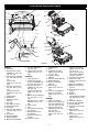
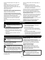
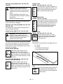
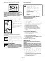
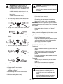
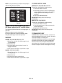
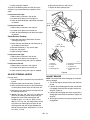
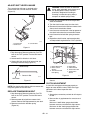
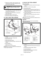
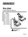
Pro Unit
Owner/Operator Manual
Models
988100 - GR1336FX
988101 - GR1536FX
988102 - GR1548FX
988103 - GR1548FL
988104 - GE1748FL
988110 - GR1332FX
988112 - GR1544FX
988114 - GR1336FXP
988115 - GR1548FXP
988118 - GR1332FXP
988119 - GR1544FXP
988313 - GR1332FXPCE
ENGLISH
FRANÇAIS
ESPAÑOL
04941300 7/03
Printed in USA
MODEL DECLARATION OF CONFORMITY ISSUED BY THE
MANUFACTURER
CERTIFICAT DE CONFORMITÉ DU MODÈLE DÉLIVRÉ PAR LE FABRICANT
VOM HERSTELLER AUSGESTELLTE
MODELL-ÜBEREINSTIMMUNGSERKLÄRUNG
MODELCERTIFICAAT VAN OVEREENSTEMMING AFGEGEVEN DOOR DE
FABRIKANT
DICHIARAZIONE DI CONFORMITÀ DEL PRODOTTO REALIZZATA DAL
PRODUTTORE
MODELO DE DECLARACIÓN DE CONFORMIDAD EMITIDA POR EL FABRICANTE
MODEL KONFORMITETSERKLÆRING UDSTEDT AF FABRIKANTEN
MODELLENS SAMSVARSERKLÆRING UTFERDIGET AV PRODUSENTEN
FÖRSÄKRAN OM MODELLÖVERENSSTÄMMELSE, UTFÄRDAT AV TILLVERKAREN
Ariens Company
655 West Ryan Street
P.O. Box 157
Brillion, Wisconsin 54110-0157
USA
Telephone (920) 756-2141
Facsimile (920) 756-2407
We the undersigned, - Je soussigné, - Mit meiner Unterschrift - Wij de ondergetekenden, - Il sottoscritto, - El abajo
firmante - Undertegnede, - Undertecknaren av detta dokument, - Me, allekirjoittaneet,
ARIENS COMPANY, declare that the Lawn Mower- certifie que la tondeuse à gazon - erklärt, dass der
Rasenmäher - verklaart dat de maaitrekker - dichiara che il tosaerba - certifica que el cortacésped - erklærer, at
græsslåmaskinen - erklærer at plenklipperen - intygar att gräsklipparen:
Category: WALK BEHIND LAWN MOWER
Make and Trade Name: GRAVELY
Model:
Serial #Range:
Cutting Width (cm):
988313
00101 & up
80.6
conform to the specifications of directive 2000/14/EC, 98/37/EC, 89/336/EEC and their current amendments.
est conforme aux spécifications des directives 2000/14/EC, 98/37/EC et 89/336/EEC et à leurs modifications
actuelles.
den Spezifikationen der Richtlinie 2000/14/EC, 98/37/EC, 89/336/EEC und deren aktuellen Zusätzen entspricht.
voldoet aan de specificaties van richtlijn 2000/14/EG, 98/37/EG, 89/336/EEG en recente aanvullingen hierop.
è conforme alle specifiche contenute nelle direttive 2000/14/EC, 98/37/EC, 89/336/EEC e nei loro relativi
amendamenti.
cumple las especificaciones de la normativa 2000/14/EC, 98/37/EC, 89/336/EEC y sus enmiendas en curso.
opfylder specifikationerne i Direktiv 2000/14/EF, 98/37/EF, 89/336/EØF og gældende ændringer.
er i overensstemmelse med spesifikasjonene i direktiv 2000/14/EF, 98/37/EF, 89/336/EØF og de gjeldende
endringer.
överensstämmer med specifikationerna i direktiven 2000/14/EC, 98/37/EC, 89/336/EEC och deras nuvarande
tillägg.
99 dBA
Representative Measured Sound Power
Level Niveau de puissance acoustique
représentatif
Repräsentativer gemessener Geräuschpegel
Typisch gemeten geluidssterkteniveau
Livello di potenza sonora rappresentativo
rilevato
Nivel de potencia acústica representativo
medido
Repræsentativt målt lydstyrkeniveau
Representativt målt lydeffektnivå
Representativ uppmätt ljudnivå
Guaranteed Sound Power Level Niveau garanti de puissance acoustique
Garantierter Geräuschpegel
Gegarandeerd geluidssterkteniveau
Livello di potenza sonora garantito
Nivel de potencia acústica garantizado
Garanteret lydstyrkeniveau
Garantert lydeffektnivå
Garanterad ljudnivå
2
100 dBA
Stated Sound Power Levels are established following Annex VIII “Full Quality Assurance” of directive 2000/14/EC.
Les déclarations de niveau de puissance acoustique sont établies conformément à l’Article VIII « Assurance
qualité totale » de la directive 2000/14/EC.
Die angegebenen Geräuschpegel wurden gemäß Anhang VIII „Totales Qualitäts-Management“ der EU-Richtlinie
2000/14/EC.
Gespecificeerde geluidssterkteniveaus zijn vastgesteld aan de hand van Annex VIII “Full Quality Assurance”
(Volledige kwaliteitsborging) van richtlijn 2000/14/EG.
I livelli di potenza sonora dichiarati sono rilevati in base all’Appendice VIII del “Controllo qualità totale” della direttiva
CE/2000/14.
Los niveles de potencia acústica se establecen siguiendo el Anexo VIII “Garantía de calidad total” de la directiva
2000/14/EC.
De anførte lydstyrkeniveauer er fastlagte efter tillæg VIII “Fuld kvalitets sikring” i direktiv 2000/14/EF.
Lydeffektnivåene er fastsatt etter tillegg VIII ”Full kvalitetssikring” i direktivet 2000/14/EF.
Fastställda ljudnivåer har etablerats enligt bilaga VIII “Full kvalitetssäkring” i direktiv 2000/14/EC.
SNCH/TUV Rheinland
11, Route de Luxembourg
L-5230 Sandweiler
Notified Body –
Entité notifiée – Benachrichtigte Körperschaft –
Certificeringsinstantie –Organismo notificato –
Cuerpo notificado – Bekendtgjort til – Kunngjøring til –
Underrättad myndighet –
Keeper of Technical File- Philip J. Smucker
Dépositaire du fichier technique - Verwalter der
technischen Dokumente - Houder technische
gegevens - Depositario del file tecnico Depositario del archivo técnico - Ansvarlig for
teknisk data - Ansvarlig for teknisk
dokumentasjon - Innehavare of teknisk fil Signature/Unterschrift/
Handtekening/Firma/
Underskrift/Underskrift
Handlekening/Underskrift/Allekirjoitus Philip J. Smucker
Manager of Product Conformance
Position/Qualité/Functie/Qualifica/Puesto/Stilling/Titel/Arvo
Ariens Company
6/11/03
Date/Datum/Dat
a/Fecha/Dato/P
äiväys
WARNING
The engine exhaust from this product
contains chemicals known to the State
of California to cause cancer, birth
defects or other reproductive harm.
3
CONTROLS AND FEATURES
13
8
7
3
3
7
9
18
17
12
18
11
4
10
5
1
OG1765
14
12
2
6
7
13
OG1730
8
7
9
3
16
11
5
15
3
14
10
4
1
OG0742
Figure 1
ENGLISH
1. Shift Lever
2. Steering Lever Latches
(988100, 101, 102, 103,
104, 110, 112)
3. Steering Levers (988100,
101, 102, 103, 104, 110,
112)
Control Levers
(988114,115, 118, 119,
313)
4. Throttle Lever (988101,
102, 103, 104, 112, 115,
119)
Throttle-Choke Lever
(988100, 114, 110, 118,
313)
5. Ignition Switch
6. PTO Switch
7. Operator Presence
Controls
8. Fuel Cap
9. Recoil Starter Handle
10. Traction Belt Guard
11. Handlebar
12. Choke Control (988101,
102, 103, 104, 112, 115,
119)
13. Hour Meter
14. Oil Light (988104)
15. Battery (988104)
16. Muffler Guard (988313)
17. Pivot Bar (988114,115,
118, 119, 313)
18. Control Stop Lock Lever
(988114,115, 118, 119,
313)
FRANÇAIS
1. Levier de vitesses
2. Verrous de la poignée
de direction (988100, 101,
102, 103, 104, 110, 112)
3. Poignées de direction
(988100, 101, 102, 103,
104, 110, 112)
Leviers de commande
(988114,115, 118, 119,
313)
4. Manette des gaz (988101,
102, 103, 104, 112, 115,
119)
Manette des gaz – Starter
(988100, 114, 110, 118,
313)
5. Clé de contact
6. PdF
7. Commandes de présence
de l’opérateur
8. Bouchon du réservoir
de carburant
9. Poignée du démarreur
à cordon
10. Garant de courroie
OG1720
de transmission
11. Guidon
12. Commande du starter
(988101, 102, 103, 104,
112, 115, 119)
13. Compteur horaire
(988104)
14. Voyant de l’huile (988104)
15. Batterie (988104)
16. Garant du silencieux
(988313)
17. Barre de pivot
(988114,115, 118, 119,
313)
18. Levier de verrouillage de
butée de commande
(988114,115, 118, 119,
313)
ESPAÑOL
1. Palanca de cambios
2. Trabas de las palancas de
la dirección (988100, 101,
102, 103, 104, 110, 112)
3. Palancas de dirección
(988100, 101, 102, 103,
104, 110, 112)
Palancas de control
(988114,115, 118, 119,
313)
4
4. Palanca del acelerador
(988101, 102, 103, 104,
112, 115, 119)
Palanca del aceleradorestrangulador (988100,
110, 114, 118, 313)
5. Interruptor de encendido
6. Palanca de la TDF
7. Controles de presencia del
operador
8. Tapón del combustible
9. Manilla de arranque de
retroceso
10. Protección de la correa de
tracción
11. Manillar
12. Control de
estrangulamiento (988101,
102, 103, 104, 112, 115,
119)
13. Horómetro (988104)
14. Luz del aceite (988104)
15. Batería (988104)
16. Protector del silenciador
(988313)
17. Barra de pivote
(988114,115, 118, 119,
313)
18. Palanca de control de
traba por tope
(988114,115, 118, 119,
313)
TABLE OF CONTENTS
Controls and Features . . . . . . . . . . . . . . . . . . . . . 4
Storage. . . . . . . . . . . . . . . . . . . . . . . . . . . . . . . . . 25
Safety . . . . . . . . . . . . . . . . . . . . . . . . . . . . . . . . . . . 6
Troubleshooting . . . . . . . . . . . . . . . . . . . . . . . . . 25
Assembly . . . . . . . . . . . . . . . . . . . . . . . . . . . . . . . 10
Accessories . . . . . . . . . . . . . . . . . . . . . . . . . . . . . 26
Operation . . . . . . . . . . . . . . . . . . . . . . . . . . . . . . . 10
Service Parts . . . . . . . . . . . . . . . . . . . . . . . . . . . . 26
Maintenance . . . . . . . . . . . . . . . . . . . . . . . . . . . . . 17
Specifications . . . . . . . . . . . . . . . . . . . . . . . . . . . 27
Service and Adjustments . . . . . . . . . . . . . . . . . . 18
Warranty. . . . . . . . . . . . . . . . . . . . . . . . . . . . . . . . 29
INTRODUCTION
THE MANUAL
PRODUCT REGISTRATION
Before operation of unit, carefully and completely read
your manuals. The contents will provide you with an
understanding of safety instructions and controls during
normal operation and maintenance.
All reference to left, right, front, or rear are given from
operator standing in operation position and facing the
direction of forward travel.
The Gravely dealer must register the product at the time
of purchase. Registering the product will help the
company process warranty claims or contact you with
the latest service information. All claims meeting
requirements during the limited warranty period will be
honored, whether or not the product registration card is
returned. Keep a proof of purchase if you do not register
your unit.
Customer Note: If Dealer does not register your
product, please fill out, sign and return the product
registration card to Gravely.
MODEL AND SERIAL NUMBERS
Transfer
model & serial
number label
from product
registration
here.
When ordering replacement parts or
making service inquiries, know the
Model and Serial numbers of your
unit and engine.
Numbers are located on the product
registration form in the unit literature
package. They are printed on a
serial number label, located on the
frame of your unit.
Serial
Number
Label
UNAUTHORIZED REPLACEMENT PARTS
Use only Gravely replacement parts. The replacement
of any part on this vehicle with anything other than a
Gravely authorized replacement part may adversely
affect the performance, durability, or safety of this unit
and may void the warranty. Gravely disclaims liability for
any claims or damages, whether warranty, property
damage, personal injury or death arising out of the use
of unauthorized replacement parts. To locate your
nearest Gravely Dealer, call 1-800-472-8359 or go to
www.gravely.com on the internet.
DISCLAIMER
Figure 2
•
OG1400
Record Engine Model and Serial numbers here.
Gravely reserves the right to discontinue, make
changes to, and add improvements upon its products at
any time without public notice or obligation.The
descriptions and specifications contained in this manual
were in effect at printing. Equipment described within
this manual may be optional. Some illustrations may not
be applicable to your unit.
DEALER DELIVERY
Dealer should:
1. Check all controls for proper function.
2. Check the safety interlock system to make sure
that it is functioning properly. (See Check Safety
Interlock System on page 17.)
3. Fill out Original Purchaser Registration Card and
return the card to Gravely.
4. Explain Limited Warranty Policy.
GB - 5
© Copyright 2003 Ariens Company
5. Explain recommended lubrication and
maintenance. Advise customer on adjustments.
6. Instruct customer on controls and operation of
unit. Discuss and emphasize the Safety
Precautions. Give customer Owner/Operator,
Parts, and Engine Manuals. Advise customer to
thoroughly read and understand them.
SAFETY
NOTATIONS
WARNING: This cutting machine is capable
of amputating hands and feet and throwing
objects. Failure to observe the safety
instructions in the manuals and on decals
could result in serious injury or death.
Slopes are a major factor related to
loss-of-control and tip-over accidents.
Operation on all slopes requires extra
caution.
Tragic accidents can occur if the operator is
not alert to the presence of children. Never
assume that children will remain where you
last saw them.
Gasoline is extremely flammable and the
vapors are explosive, handle with care.
Disengage attachment, stop unit and engine,
remove key, engage parking brake, and allow
moving parts to stop before leaving operator’s
position.
NOTE: General reference information for proper
operation and maintenance practices.
IMPORTANT: Specific procedures or information
required to prevent damage to unit or attachment.
PRACTICES AND LAWS
Practice usual and customary safe working
precautions, for the benefit of yourself and others.
Understand and follow all safety messages. Be alert to
unsafe conditions and the possibility of minor,
moderate, or serious injury or death. Learn applicable
rules and laws in your area, including those that may
restrict the age of the operator.
REQUIRED OPERATOR TRAINING
Original purchaser of this unit was instructed by the
seller on safe and proper operation. If unit is to be used
by someone other than original purchaser; loaned,
rented or sold, ALWAYS provide this manual and any
needed safety training before operation.
SAFETY ALERTS
Look for these symbols to point out
important safety precautions. They mean:
Attention!
SAFETY DECALS AND LOCATIONS
ALWAYS replace missing or damaged Safety Decals.
Refer to figures below for Safety Decal locations.
Personal Safety Is Involved!
DANGER / PELIGRO
Become Alert!
Obey The Message!
TO AVOID SERIOUS INJURY OR DEATH: • Read the operator's
manual. • Keep children and others away from unit while
operating. • Never direct discharge toward other people.
Thrown objects can cause injury. • Keep safety devices
(guards, switches, etc.) in place and working. • Check
interlock system per manual before use. • Never allow
operation by untrained persons.
• When parking on a slope always
engage parking brake. • Disengage
PTO, stop unit and engine, set
parking brake and remove key
before making any inspections,
repairs, etc.
• Mantenga artefactos de seguridad (guardas, interruptores, etc.) en su lugar y trabajando. • Verifique en el manual el sistema
• Maintenez toujours en place tous les
de engranar antes de usar. • Mo permitir que personal sin la necesaria formación use la máquina. • Cuando se estacione en una
elements de sécurité (garants, interupteurs,
pendiente, activar siempre el freno de estacionamiento. • Desactivar la TDF, detener la unidad, apagar el motor, accionar el
etc.). • Controler le bon fonctionnement du
freno de estacionamiento y quitar la llave antes de realizar cualquier inspección, reparación, etc.
système de sécurité avant utilisation tel
qu'indiqué dans le manuel d'utilisation. • Ne
jamais permettre l'utilisation par des personnes
n'ayant pas reçu la formation nécessaire. • En
cas de stationnement en pente, toujours serrer
le frein de stationnement. • Désenclencher la
PdF, arrêter la machine et le moteur, serrer le
frein de stationnement et enlever la clé de
contact avant de commencer toute vérification,
réparation, etc.
1
05356500C
The safety alert symbols above and signal words below
are used on decals and in this manual.
Read and understand all safety messages.
2
DANGER/ PELIGRO
4
DANGER/PELIGRO
Stay clear of rotating parts.
07731400D
Rester à l’écart des pièces
en rotation.
Mantenerse alejado de las
piezas giratorias.
05236900A
DANGER: IMMINENTLY HAZARDOUS
SITUATION! If not avoided, WILL RESULT in
death or serious injury.
2
DANGER/ PELIGRO
07731400D
WARNING: POTENTIALLY HAZARDOUS
SITUATION! If not avoided, COULD
RESULT in death or serious injury.
3
WARNING/AVERTISSEMENT/ADVERTENCIA
07742300B
Do not operate mower Ne jamais utiliser No operar segadora a
menos que las defensas
la tondeuse sans
unless guards are in
esten en posicion de
operating position or protecteur sur le
canal d'ejection ou operacion o el
bagger is attached.
sans le bac monte. recogedor este fijo.
Figure 3
CAUTION: POTENTIALLY HAZARDOUS
SITUATION! If not avoided, MAY RESULT in
minor or moderate injury. It may also be
used to alert against unsafe practices.
GB - 6
OG1490
1
2. Danger! Rotating Blades
TO AVOID SERIOUS INJURY OR DEATH: • Read the
operator's manual. • Keep children and others away from unit
while operating. • Never direct discharge toward other people.
Thrown objects can cause injury. • Keep safety devices (guards,
shields, switches, etc.) in place and working. • Check interlock
system per manual before use. • Never allow operation by
untrained persons. • When parking on a slope always engage
parking brake. • Disengage PTO, stop unit and engine, set
parking brake and remove key before making any inspections,
repairs, etc.
DANGER / PELIGRO
ROTATING BLADE! Keep hands and
feet away.
.80
x
1.36
DANGER
PELIGRO
• Maintenez toujours en place tous les elements de sécurité (garants, interupteurs, etc.). • Controler le bon
fonctionnement du système de sécurité avant utilisation tel qu'indiqué dans le manuel d'utilisation. • Ne
jamais permettre l'utilisation par des personnes n'ayant pas reçu la formation nécessaire. • En cas de
stationnement en pente, toujours serrer le frein de stationnement. • Désenclencher la PdF, arrêter la machine
et le moteur, serrer le frein de stationnement et enlever la clé de contact avant de commencer toute
vérification, réparation, etc.
• Mantenga artefactos de seguridad (guardas, interruptores, etc.) en su lugar y trabajando. • Verifique en el
manual el sistema de engranar antes de usar. • Mo permitir que personal sin la necesaria formación use la
máquina. • Cuando se estacione en una pendiente, activar siempre el freno de estacionamiento. • Desactivar
la TDF, detener la unidad, apagar el motor, accionar el freno de estacionamiento y quitar la llave antes de
realizar cualquier inspección, reparación, etc.
05357800A
OL3030
2
DANGER/ PELIGRO
4
Always stand clear of discharge area.
DO NOT direct discharge toward other
people. Remove objects that could be
thrown by the blade. DO NOT operate
mower over gravel and hard surfaces.
07731400D
DANGER/PELIGRO
Stay clear of rotating parts.
Rester à l’écart des pièces
en rotation.
Mantenerse alejado de las
piezas giratorias.
05236900A
OL0910
2
Keep people and pets away when
operating unit. Keep children out of the
work area and under the watchful care
of a responsible adult.
DANGER/PELIGRO
07731400D
OL4370
3
Shut off engine, remove key, read
manual before you unplug, adjust or
repair unit.
WARNING/AVERTISSEMENT/ADVERTENCIA
07742300B
Do not operate mower Ne jamais utiliser No operar segadora a
unless guards are in
la tondeuse sans
menos que las defensas
operating position or protecteur sur le
esten en posicion de
bagger is attached.
canal d'ejection ou operacion o el
sans le bac monte. recogedor este fijo.
Figure 4
OL4010
OG1497
NO STEP! Always keep feet away from
rotating parts.
1. Danger! To avoid serious injury or death
Read the operator’s manual.
OL4420
3. Warning!
OL1801
Always stand clear of discharge.
Keep children and others away from unit
while operating.
OL0910
OL4370
DO NOT operate mower unless guards
are in operating position or bagger is
attached.
Never direct discharge toward other
people. Thrown objects can cause injury.
OL3320
OL0910
•
•
•
•
•
Keep safety devices (guards, shields,
switches, etc.) in place and working.
Check interlock system per manual before
use.
Never allow operation by untrained persons.
When parking on a slope always chock or
block the wheels.
Disengage PTO, stop unit and engine, set
parking brake and remove key before making
any inspections, repairs, etc.
4. Danger!
Stay clear of rotating parts.
OL5100
SAFETY RULES
Read, understand and follow all safety practices in
Owner/Operator Manual before beginning assembly.
Failure to follow instructions could result in personal
injury and/or damage to unit.
ALWAYS remove key (if equipped) and disconnect wire
from spark plug before assembly. Unintentional engine
start up can cause death or serious injury.
GB - 7
Complete a walk around inspection of unit and work
area to understand:
• Work area
• Your unit
• All safety decals
ALWAYS check overhead and side clearances carefully
before operation.
ALWAYS be aware of traffic when operating along
streets or curbs.
Keep children and people away.
Keep children out of work area and under watchful care
of a responsible adult.
Keep area of operation clear of all toys, pets, and
debris. Thrown objects can cause injury.
Check for weak spots on docks, ramps or floors. Avoid
uneven work areas and rough terrain.
ALWAYS be sure of your footing. Keep a firm hold on
handlebar. Walk, NEVER run.
DO NOT operate on wet grass.
Dust, smoke, fog, etc. can reduce vision and cause an
accident. Operate unit only when there is good visibility
and light.
Read the entire Owner/Operator manual and other
training material. If the operator or the mechanic
cannot read the manual, it is the owner’s responsibility
to explain it to them. Only the user can prevent and is
responsible for accidents or injuries occurring to
themselves, other people or property.
• Only trained adults may operate or service unit
• Training includes actual operation
NEVER allow children to operate or play on or near
unit.
Be alert and shut off unit if children enter area.
Never carry passengers.
NEVER operate unit after or during the use of
medication, drugs or alcohol. Safe operation requires
your complete and unimpaired attention at all times.
NEVER allow anyone to operate this unit when their
alertness or coordination is impaired.
Wear adequate safety gear, protective gloves and
footwear.
NEVER wear open sandals or canvas shoes during
operation.
Protect eyes, face and head from objects that may be
thrown from unit. Wear appropriate hearing protection.
Sharp edges can cut. Moving parts can cut off fingers
or a hand. Wrap blade(s), wear sturdy gloves and use
extreme caution when servicing. On multi-blade
mowers, rotation of one blade will cause all blades to
rotate.
ALWAYS keep hands and feet away from all rotating
parts during operation. Rotating parts can cut off body
parts.
ALWAYS keep hands away from all pinch points.
DO NOT touch unit parts which might be hot from
operation. Allow parts to cool before attempting to
maintain, adjust or service.
NEVER place your hands or any part of your body or
clothing inside or near any moving part while unit is
running.
DO NOT wear loose clothing or jewelry. Tie back hair
that may get caught in rotating parts.
Keep children and people away from unit during
operation.
Fumes from engine exhaust can cause injury or death.
DO NOT run engine in an enclosed area. Always
provide good ventilation.
Thrown objects can cause injury and property damage.
DO NOT point discharge at anyone or discharge
directly onto paved or gravel surfaces.
Always stand clear of the discharge area when
operating this unit.
Read, understand, and follow all instructions in the
manual and on the machine before starting.
Understand:
• How to operate all controls
• The functions of all controls
• How to STOP in an Emergency
• Braking and steering characteristics
• Turning radius and clearance
ALWAYS keep protective structures, guards, and
panels in good repair, in place and securely fastened.
NEVER modify or remove safety devices.
ALWAYS keep discharge cover or complete grass
catcher in place and in proper working condition.
Check steering control operation frequently. Adjust and
service as required.
Safety Interlock System must function properly. DO
NOT operate unit if operator presence control is
damaged or disabled.
If you strike an object, or if equipment vibrates
abnormally, stop engine at once, disengage PTO, wait
for all moving parts to stop, and remove key. Check for
any damage or loose parts. Repair before restart.
Before starting engine: disengage PTO and place unit
in neutral.
DO NOT operate at too fast a rate. DO NOT change
engine governor settings or over-speed engine. Slow
down and turn corners slowly.
GB - 8
Disengage PTO when attachment is not in use. DO
NOT raise deck with blades running. ALWAYS turn off
power to attachment when travelling, crossing
driveways, etc.
Avoid uneven and rough terrain. DO NOT operate near
drop offs, ditches, or embankments. Unit can suddenly
turn over if a wheel is over the edge of a cliff or ditch, or
if an edge caves in.
DO NOT try to stabilize unit by putting foot on ground
when operating with applicable riding attachments.
When engine is running and speed control lever is
forward, holding only one steering lever will cause unit
to circle around one drive wheel.
Use care when approaching blind corners, shrubs,
trees or other objects that may obscure view.
ALWAYS disengage PTO, stop unit and engine,
remove key and allow moving parts to stop before
clearing clogs or cleaning unit.
Never leave a running unit unattended. ALWAYS shut
off engine before leaving unit.
ALWAYS remove key to prevent unauthorized use.
DO NOT operate in reverse unless absolutely
necessary. ALWAYS backup slowly. ALWAYS look
down and behind, before and while backing.
DO NOT operate on steep slopes. DO NOT operate on
slopes of more than 10°. Operate across the face of
slopes, not up and down.
Turf conditions can affect the unit’s stability.
Keep all movement on slopes slow and gradual. DO
NOT make sudden changes in speed or direction. Use
a slow speed to avoid stopping or shifting on slopes.
Avoid starting or stopping on a slope.
DO NOT park unit on a slope unless absolutely
necessary. When parking on a slope always chock or
block wheels.
Use extra care when loading or unloading unit onto
trailer or truck.
Secure unit chassis to transport vehicle. NEVER
secure from rods or linkages that could be damaged.
DO NOT transport machine while engine is running.
Keep unit free of grass, leaves, or other debris. Clean
up oil or fuel spills.
This product is equipped with an internal combustion
engine. DO NOT use on or near any unimproved, forest
covered or brush covered land unless the exhaust
system is equipped with a spark arrester meeting
applicable local, state or federal laws. A spark arrester,
if used, must be maintained in effective working order
by the operator.
Fuel is highly flammable and its vapors are explosive.
Handle with care. Use an approved fuel container.
No smoking, No sparks, No flames. ALWAYS allow
engine to cool before servicing.
NEVER fill fuel tank when engine is running or hot from
operation.
NEVER fill or drain fuel tank indoors.
Replace fuel cap securely and clean up spilled fuel.
Never fill containers inside a vehicle or on a truck or
trailer bed with a plastic liner. Always place containers
on the ground away from your vehicle before filling.
When practical, remove gas-powered equipment from
the truck or trailer and refuel it on the ground. If this is
not possible, then refuel such equipment on a trailer
with a portable container, rather than from a gasoline
dispenser nozzle.
Keep the nozzle in contact with the rim of the fuel tank
or container opening at all times until fueling is
complete. Do not use a nozzle lock-open device.
If fuel is spilled on clothing, change clothing
immediately.
NEVER store fuel inside where there is an open flame,
such as a water heater.
Avoid Electric Shock. Objects contacting both battery
terminals at the same time may result in injury and unit
damage. DO NOT reverse battery connections.
Reverse connections may result in sparks which can
cause serious injury. Always connect positive (+) lead
of charger to positive (+) terminal, and negative (-) lead
to negative (-) terminal.
ALWAYS disconnect negative (-) cable FIRST and
positive (+) cable SECOND. ALWAYS connect positive
(+) cable FIRST, and negative (-) cable SECOND.
Explosive Gases from battery can cause death or
serious injury. Poisonous battery fluid contains sulfuric
acid and its contact with skin, eyes or clothing can
cause severe chemical burns.
No flames, No sparks, No smoking near battery.
ALWAYS wear safety glasses and protective gear near
battery. Use insulated tools.
DO NOT TIP battery beyond a 45˚ angle in any
direction.
ALWAYS keep batteries out of reach of children.
Battery posts, terminals and related accessories
contain lead and lead compounds, chemicals known to
the State of California to cause cancer and
reproductive harm. Wash hands after handling.
Reverse connections may cause sparks which may
result in injury. ALWAYS connect/disconnect cables in
proper order.
Poisonous battery fluid contains sulfuric acid and its
contact with skin, eyes, or clothing can cause severe
burns.
Explosive Gases! No flames, No sparks, No smoking
near battery.
ALWAYS wear safety glasses and protective gear near
battery.
GB - 9
DO NOT TIP battery beyond a 45° angle in any
direction.
ALWAYS keep batteries out of reach of children.
Before making any inspections, repairs, etc.:
disengage PTO, stop unit and engine, remove key,
allow moving parts to stop.
Allow hot parts to cool.
ALWAYS block wheels, engage parking brake and
know all jack stands are strong, secure and will hold
weight of unit during maintenance.
An extension spring, when extended, stores energy
and can be dangerous. Always use tools specifically
designed for installing or removing an extension spring.
Always compress or extend springs slowly.
ALWAYS maintain unit in safe operating condition.
Damaged or worn out muffler can cause fire or
explosion.
Keep hardware, especially blade attachment bolts,
tight.
Maintain or replace safety and instruction labels, as
necessary.
For unit storage or extended storage:
• NEVER store with fuel in fuel tank, inside a
building where any ignition sources are present.
• Allow engine to cool completely.
Use only attachments or accessories designed for your
unit and that can be used safely on your terrain.
Check attachment components frequently for wear,
damage or deterioration. Replace with manufacturer’s
recommended parts for safety.
To reduce fire hazard and overheating, keep equipment
free of grass, leaves, debris or excessive lubricants.
Use extra care with grass catchers and other
attachments. These can change the stability of the unit.
Use only approved hitch points.
ALWAYS be aware of attachments when turning.
ALWAYS allow adequate clearance between
attachments, personnel, and other objects.
ASSEMBLY
5. Check engine oil level. See engine manual.
6. Add clean fuel to the fuel tank. See engine
manual for type and grade.
7. Check for loose hardware.
8. Be sure that safety interlock system operates
correctly. See Check Safety Interlock System on
page 17.
9. Be sure that unit tracks straight.
Unit must not pull sharply to the left or right when
the steering levers are released. See Adjusting
the Unit to Track Straight on page 18.
WARNING: AVOID INJURY. Read and
understand the entire Safety section before
proceeding.
1. Remove the unit from shipping container.
2. Adjust tire pressure to 8 to 16 psi (55 to 110 kPa).
3. Service and connect battery. See Charge Battery
on page 22.
4. Check the adjustments outlined in Service &
Adjustments.
OPERATION
WARNING: AVOID INJURY. Read and
understand the entire Safety section before
proceeding.
CONTROLS AND FEATURES
Safety Interlock System
DANGER: SAFETY INTERLOCK SYSTEM
FAILURE and improper operation of unit can
result in death or serious injury. ALWAYS
know the safety interlock system is operating
properly. See Check Safety Interlock System
on page 17 for testing instructions.
Operator Presence Control (988100, 101, 102,
103, 104, 110, 112)
The operator presence control lever must be
depressed to operate the PTO or traction drive. When
the shift lever or PTO is engaged, releasing the
operator presence control lever stops the engine.
Operator Presence Control
(988114, 115, 118, 119, 313)
The operator presence control levers must be
depressed to operate the PTO. When the PTO is
engaged, releasing the operator presence control
levers stops the mower blades.
CAUTION: AVOID INJURY. Operate only
when operator presence control is
functioning correctly. See Check Safety
Interlock System on page 17 for testing
instructions.
The engine will only start with the PTO disengaged.
Pistol grip models must have the shift lever in neutral
for engine to start.
GB - 10
Steering Levers (988100, 101, 102, 103, 104,
110, 112)
Throttle Lever
(988101, 102, 103, 104, 112, 115, 119)
The throttle lever changes the speed of the
engine. Move the throttle lever to Fast (1) to
increase engine speed. Move the lever to
Slow (2) to decrease engine speed.
1
WARNING: AVOID INJURY. When the
engine is running and the shift lever is
engaged, releasing only one steering latch
causes the unit to circle around one drive
wheel.
ALWAYS hold both steering levers in the
neutral position when releasing the steering
lever latches.
ALWAYS release levers slowly.
2
OG1180
Throttle/Choke Lever
(988100, 110, 114, 118, 313)
The steering levers are used to steer, operate in
forward and reverse, and stop the unit. When held in
neutral, the brakes are engaged.
The Throttle/Choke lever changes the speed
of the engine and chokes the engine for cold
starts. Place the lever in Choke (1) to start a
cold engine. Move the lever to Fast (2) to
increase engine speed. Move the lever to
Slow (3) to decrease engine speed.
1
2
Steering Lever Latches (988100, 101, 102, 103,
104, 110, 112)
The steering lever latches hold the steering levers in
neutral and apply the brakes.
3
OG1061
Control Levers (988114, 115, 118, 119, 313)
Choke Control
(988101, 102, 103, 104, 112, 115, 119)
WARNING: AVOID INJURY. When the
engine is running and the shift lever is
engaged, moving only one lever causes the
unit to circle around one drive wheel.
ALWAYS move levers slowly.
OG1190
The control levers are used to steer, operate in forward
and reverse, and stop the unit. Push forward to move
forward. Shift into reverse and pull up on the lower
control levers to move in reverse. When held in neutral,
the brakes are engaged.
Ignition Switch (988104)
1
2
The shift lever sets the direction and speed of the unit.
R = reverse
N = neutral
1 = the slowest forward speed
5 = the fastest forward speed.
N
1
2
OF1210
3
4
Operate the ignition switch with the
removable key. The switch has three
positions: Off (1), On (2) and Start (3). To
start the engine, turn the key to Start, then
release to On. To stop the engine, turn the
key to Off.
Shift Lever
R
3
Use the choke control to start a cold
engine. Pull the control out to choke the
engine. Push the control in when the
engine gets warm.
5
Ignition Switch (988100, 101, 102, 103, 110,
112, 114, 115, 118, 119, 313)
1
2
OF1212
Operate the ignition switch with the
removable key. The switch uses two
positions: Off (1) and On (2). To start the
engine, turn the key to On (2) and pull the
recoil handle. To stop the engine, turn the
key to Off (1).
OG1040
PTO Clutch (988100, 101, 102, 103, 104, 110,
112)
1
2
OE0260
GB - 11
Pull the PTO (power take off) switch On
(1) to engage the mower blades. Push
the PTO switch Off (2) to disengage the
mower blades.
FILL FUEL TANK
PTO Clutch (988114, 115, 118, 119, 313)
WARNING: Fuel is highly flammable and its
vapors are explosive. Handle with care. Use
an approved fuel container.
NO smoking, NO sparks, NO flames.
ALWAYS allow engine to cool before
servicing.
NEVER fill fuel tank when engine is running
or hot from operation.
NEVER fill or drain fuel tank indoors.
Replace fuel cap securely and clean up
spilled fuel.
1
2
3
OE0261
Pull the PTO (power take off) switch past On (1) to
Reset (2) to engage the mower blades. Push the PTO
switch Off (3) to disengage the mower blades.
NOTE: Pull PTO switch to Reset (2) to engage mower
blades after operator presence control has been
released.
Parking Brake (988114, 115, 118, 119, 313)
1
2
The pivot bar can hold the
tractor in position when not in
use.
To engage brake, loosen pivot
bar (1).
Pull pivot bar back against the
steering levers and lock in
position (2).
Add fuel to the fuel tank as needed. See engine
manual for type and grade of fuel.
To add fuel to the fuel tank:
1. Put the unit in an open area.
2. Stop the engine.
3. Allow engine to cool.
4. Clean the fuel cap and the area around the fuel
cap to prevent dirt from entering the fuel tank.
5. Remove the cap from the fuel tank.
6. Fill the fuel tank. Be careful not to spill.
7. Install the cap on the fuel tank and tighten.
8. Clean up any spilled fuel before starting the
engine.
TO STOP IN AN EMERGENCY
1.
2.
3.
4.
Recoil Starter Handle
Pull the recoil starter handle to start the engine.
Hour Meter
Electric Start: The hour meter measures
the number of hours that the key is in the
run position and operator presence control
OG0620
is engaged.
Recoil Start: The hour meter measures the number of
hours the engine is running.
Release operator presence control(s).
Turn the ignition key Off.
Allow engine to stop completely.
Lock steering levers in neutral (988100, 101, 102,
103, 104, 110, 112).
0 0 0 0 0 0
HOURS
1/10
Oil Pressure Light (988104)
OG0600
The red light near this symbol comes on
when the engine is running and engine oil
pressure is low. Check oil level and add if
necessary. See Engine Manual.
STARTING AND SHUT OFF
Before Each Use
Check each item in Each Use in the Maintenance
Schedule.
NOTE: On 988100, 101, 102, 103, 104, 110, 112 the
engine will not start unless the shift lever is in neutral
and the Power Take Off (PTO) is Off. On 988114, 115,
118, 119, 313 the engine will not start unless the Power
Take Off (PTO) is off.
Recoil Start (988100, 101, 102, 103, 110, 112)
1.
2.
3.
4.
Lock the steering lever latches in neutral.
Put the shift lever in neutral.
Move PTO switch to Off.
Set throttle to the proper starting position. If the
engine is cold, choke the engine.
5. Turn ignition switch to On.
GB - 12
6. Grasp recoil starter handle and pull rope out
slowly until it pulls harder. This is the compression
stroke.
7. Let the rope rewind slowly.
8. Pull rope with rapid continuous full arm stroke to
start engine. Allow rope to rewind slowly.
IMPORTANT: DO NOT let starter handle snap against
engine.
9. Repeat until engine starts. (If engine does not
start, refer to Engine Manual.)
10. After engine starts, adjust choke as needed.
Allow engine to warm and run smoothly before
operating unit.
Recoil Start (988114, 115, 118, 119, 313)
1.
2.
3.
4.
5.
8. After engine starts, adjust choke as needed.
Allow engine to warm and run smoothly before
operating unit.
Shut Off
1. Lock steering levers in neutral (988100, 101, 102,
103, 104, 110, 112) .
Bring control levers to neutral (988114, 115, 118,
119, 313).
2. Move the throttle lever to Slow.
3. Put the shift lever in neutral.
4. Turn the ignition key Off.
5. Allow engine to stop completely.
TO OPERATE UNIT
Engage the parking brake.
Bring control levers to neutral.
Put the shift lever in neutral.
Move PTO switch to Off.
Set throttle to the proper starting position. If the
engine is cold, choke the engine.
6. Turn ignition switch to On.
7. Grasp recoil starter handle and pull rope out
slowly until it pulls harder. This is the compression
stroke.
8. Let the rope rewind slowly.
9. Pull rope with rapid continuous full arm stroke to
start engine. Allow rope to rewind slowly.
IMPORTANT: DO NOT let starter handle snap against
engine.
10. Repeat until engine starts. (If engine does not
start, refer to Engine Manual.)
11. After engine starts, adjust choke as needed.
Allow engine to warm and run smoothly before
operating unit.
Operate the unit only in the operator’s position directly
behind the handlebars.
Electric Start (988104)
To operate:
WARNING: AVOID INJURY. When the
engine is running and the speed control
lever is engaged, holding only one steering
lever in neutral causes the unit to circle
sharply around one drive wheel.
988100, 101, 102, 103, 104, 110, 112
To shift unit:
1. Stop unit movement by pulling both steering
levers all the way up.
2. You can move the shift lever one of two ways:
• Continue to hold up both steering levers and use
your knee to move the shift lever to the desired
position.
• Lock both steering levers. Move the shift lever to
the desired position. Hold the steering levers up
as you unlock them.
3. Release both steering levers slowly.
To start the engine:
1. Lock the steering lever latches in neutral.
2. Put the shift lever in neutral.
3. Move PTO switch to Off.
4. If the engine is cold, choke the engine.
5. Move the throttle to Fast.
6. Put the ignition key in the switch and turn it to
Start.
IMPORTANT: DO NOT operate starter motor more
than 15 seconds per minute, as overheating and
damage can occur. If engine will not start, refer to
Troubleshooting or Engine Manual.
7. When the engine starts, release the key to Run
position.
1. Start the engine (See Starting and Shut Off on
page 12).
2. Move the throttle lever to the Fast position.
3. Engage the operator presence control and move
shift lever to desired direction and speed.
4. Hold steering levers in neutral and release
steering latch levers.
GB - 13
WARNING: AVOID INJURY. When the
engine is running and the shift lever is
engaged, releasing only one steering latch
causes the unit to circle around one drive
wheel.
ALWAYS hold both steering levers in the
neutral position when releasing the steering
lever latches.
ALWAYS release levers slowly.
•
WARNING: Uncontrolled reverse travel can
result in serious injury.
Do not put shift lever into the reverse
position unless you are prepared to operate
in reverse.
To move straight forward; slowly release both
steering levers to the full outward position.
OG1410
•
To stop unit in neutral, hold levers in the neutral
position.
OG1420
•
To lock unit in neutral, engage both steering
latches.
To mow:
1. Lock steering levers in neutral.
2. Put the shift lever in neutral.
3. Move the throttle lever to the fast position.
4. Engage the operator presence control lever.
5. Move the PTO switch to On to engage mower.
IMPORTANT: NEVER engage the PTO if the mower is
plugged with grass or other material. This will damage
the PTO belt.
6. Move the shift lever to set a slow ground speed.
7. Hold steering levers in neutral and release
latches.
8. Release steering levers slowly.
When you know how to operate the unit, select a speed
appropriate to your mowing conditions.
To stop mowing:
1. Lock the steering levers in neutral.
2. Keep one hand on the operator presence control
and move the shift lever to the neutral position.
3. Move the throttle lever to 1/2 speed.
4. Turn off PTO switch.
OG1430
•
To turn to the left, pull the left hand lever up.
•
To turn to the right, pull the right hand lever up.
988114, 115, 118, 119, 313
OG1440
OG1450
To move in reverse:
1. Place steering levers in neutral.
2. Engage steering lever latches.
3. Engage the operator presence control and move
shift lever to Reverse.
4. Hold steering levers in neutral and release
latches.
5. Release steering levers slowly.
To shift unit:
1. Stop unit movement by bringing control levers to
neutral.
2. With control levers in neutral, use your knee or
hand to move the shift lever to the desired
position.
3. Push both control levers forward slowly to move
in selected direction.
To operate:
1. Start the engine (See Starting and Shut Off on
page 12).
2. Move the throttle lever to the Fast position.
3. Move shift lever to desired direction and speed.
4. Engage operator presence control.
GB - 14
WARNING: AVOID INJURY. When the
engine is running and the shift lever is
engaged, using one steering control lever
causes the unit to circle around one drive
wheel.
ALWAYS hold both steering levers when
operating unit and move levers slowly.
•
To move straight forward, slowly push control
levers forward.
OG1600
•
To stop unit motion, allow control levers to return
to neutral.
OG1610
•
To turn to the left, push the right hand control
lever forward.
OG1630
•
To turn to the right, push the left hand control
lever forward.
NOTE: Operator presence control must remain
engaged.
4. Move the PTO switch to On to engage mower.
IMPORTANT: NEVER engage the PTO if the mower is
plugged with grass or other material. This will damage
the PTO belt.
5. Push control levers forward slowly.
When you know how to operate the unit, select a speed
appropriate to your mowing conditions.
To stop mowing:
1. Allow control levers to return to neutral.
2. Move the throttle lever to 1/2 speed.
3. Turn off PTO switch.
4. Move shift lever to the neutral position.
CUTTING HEIGHT ADJUSTMENT
Fixed Decks (988100, 101, 102, 110, 112, 114,
115, 118, 119, 313)
1. Shut off the unit. See Shut Off on page 13 and
"To stop mowing."
2. Lift deck by handle until mower lock pins can be
pulled out of holes.
3. Turn latches slightly so they can’t snap back into
place.
4. Set deck to desired cutting height (Figure 5).
5. Place mower lock pins into desired hole.
IMPORTANT: Make sure lock pins are fully engaged.
6. Repeat adjustment for other side of deck.
OG1640
Fixed Deck Cutting Heights
To move in reverse:
1. Allow control levers to return to neutral.
2. Move shift lever to Reverse.
3. Pull up slowly on the lower control levers.
Inches (mm)
1 (25)
(38) 1.5
2 (51)
(64) 2.5
3 (76)
(90) 3.5
OG1660
WARNING: Uncontrolled reverse travel can
result in serious injury.
Do not put shift lever into the reverse
position unless you are prepared to operate
in reverse.
4 (102)
Figure 5
OG1380
Floating Decks (988103, 104)
1. Shut off the unit. See Shut Off on page 13 and
"To stop mowing."
2. Lift deck by handle until hair pins can be removed
from height adjustment rods.
3. Set deck to desired cutting height (Figure 6).
4. Insert hair pins into appropriate holes on height
adjusting rods.
5. Repeat adjustment for other side of deck.
To mow:
1. Move the shift lever to set a slow ground speed.
2. Move the throttle lever to the fast position.
3. Engage operator presence control(s).
GB - 15
NOTE: It may be necessary to adjust cutting height in
steps to keep deck from binding.
1 (25)
1.5 (38)
2 (51)
2.5 (64)
3 (76)
3.5 (90)
4 (102)
Figure 6
988100, 101, 102, 103, 104, 110, 112
To move the unit without the engine running:
1. Put the shift lever in neutral.
2. Hold steering levers in neutral and disengage
latches. Release steering levers. The brake is
disengaged when the steering levers are
released.
3. Push unit to desired location.
IMPORTANT: Towing the unit will damage
transmission.
Floating Deck Cutting Heights
Inches
(mm)
TO PUSH UNIT BY HAND
988114, 115, 118, 119, 313
OG1385
LAWN STRIPER ADJUSTMENT (44" and
48" decks; optional on 32" and 36" decks)
The striper drags behind the deck and shapes grass as
you mow.
Adjust the striper to match cutting height.
Short grass (deck low): mount from bottom holes.
Tall grass (deck high): mount from top holes.
PARKING
988100, 101, 102, 103, 104, 110, 112
1. Shut off the unit. See Shut Off on page 13 and
"To stop mowing."
2. Remove the key.
3. Lock both steering lever latches in neutral to
engage the brakes.
4. Chock or block the wheels if parked on a slope.
To move the unit without the engine running:
1. Put the shift lever in neutral.
2. Push the control levers all the way forward to
release the brakes.
3. Push unit to desired location.
IMPORTANT: Towing the unit will damage the
transmission.
TO TRANSPORT UNIT
ALWAYS shut off engine, remove key and drain fuel
when transporting unit on a truck or trailer. Use extra
care when loading or unloading unit.
Lock both steering lever latches in neutral to engage
the brakes, or lock pivot bar against control levers.
Secure unit chassis to transport vehicle. NEVER
secure from rods or linkages that could be damaged.
DO NOT transport machine while engine is running.
988114, 115, 118, 119, 313
1. Shut off the unit. See Shut Off on page 13 and
"To stop mowing."
2. Remove the key.
3. Lock pivot bar against control levers.
4. Chock or block the wheels if parked on a slope.
GB - 16
MAINTENANCE
3. Disengage PTO.
The engine MUST stop whenever the operator
removes both hands from controls while the PTO or
transmission is engaged. To test:
1. Start engine and engage PTO.
2. Release operator presence control lever(s).
Engine must stop.
3. Disengage PTO.
4. Restart engine.
5. Place shift lever in Forward.
6. Release operator presence control lever. Engine
must stop.
WARNING: AVOID INJURY. Read and
understand the entire Safety section before
proceeding.
MAINTENANCE SCHEDULE
Each
Use
Check Safety Interlock
System
•
Check Air Cleaner
•
Check Engine Oil
•
Check Engine Cooling
•
Check Fasteners
•
Check Tire Pressure
•
25
50
100
988114, 115, 118, 119, 313
Check Battery and Battery
Fluid
•
Check All Belts
•
Mower Blades
•
Clean Air Cleaner Foam
Element
•
General Lubrication
Blades must not rotate unless the operator presence
control levers and PTO are engaged. To Test:
1. With engine on, release operator presence
controls and engage PTO.
2. Blades must not rotate.
3. Disengage PTO.
The blades MUST stop whenever the operator
removes both hands from controls while the PTO is
engaged. To test:
1. Start engine and engage PTO.
2. Release operator presence control lever(s).
Blades must stop.
NOTE: All motion must stop whenever operator
releases control levers.
•
Change Engine Oil
*•
Check Fuel Filter
•
Check Spark Plug
•
Check Muffler
•
Clean Air Cleaner Paper
Element
•
CHECK AIR CLEANER
Check the air cleaner element before each use. See
engine manual for detailed instructions.
CHECK ENGINE OIL
100 hours thereafter.
Check the engine oil level before each use. Never
operate the engine when the oil level is low. See engine
manual for detailed instructions.
CHECK SAFETY INTERLOCK SYSTEM
CHECK ENGINE COOLING
Test the safety interlock system at each operation. If
the system does not function properly, do not operate
the unit until repairs are made.
Check the engine air cooling system before each use.
See engine manual for detailed instructions.
* Change oil after first 8 hours of operation and every
CHECK FASTENERS
988100, 101, 102, 103, 104, 110, 112
Engine must not start unless PTO is disengaged and
the shift lever is in neutral. To test:
1. With engine off, engage PTO.
2. Turn electric start model ignition switch to Start.
Engine must not crank.
Turn recoil start model ignition switch to On. Pull
recoil start handle. Engine must not start.
Check all nuts, bolts, and other fasteners before each
use. Replace missing or damaged fasteners.
CHECK TIRE PRESSURE
Check tires for proper inflation, excessive wear or
damage before each use. The correct air pressure is
8 to 16 psi (55 to 110 kPa).
GB - 17
CHECK BATTERY (988104)
GENERAL LUBRICATION
Apply a small amount of oil to the pivot points as
required for smooth operation (Figure 7).
Apply high quality lithium based grease to all lube
fittings every 50 hours of operation.
NOTE: The mower spindle assembly is maintenance
free.
WARNING: AVOID INJURY. Read and
understand the entire Safety section before
proceeding.
WARNING: Battery posts, terminals and
related accessories contain lead and lead
compounds, chemicals known to the State of
California to cause cancer and reproductive
harm. Wash hands after handling.
2
Terminals
Inspect battery and terminals every 25 hours.
To clean terminals:
1. Remove battery cover.
2. Remove battery cables from terminals.
3. Clean or service battery away from unit. Remove
corrosion from battery terminals and cable
connections with wire brush, then wash with a
weak baking soda solution.
4. Apply a thin coat of dielectric grease or petroleum
jelly to terminals and cable ends to retard
corrosion.
5. Replace battery and secure with battery cover.
CHECK ALL BELTS
Check all belts for wear or damage every 25 hours. If
belts slip, check for damaged belts or tensioner.
1
OG1485
2
1. Half Shafts
2. Wheel Bearings
Figure 7
CHANGE ENGINE OIL
Open the petcock to drain oil through oil drain hole on
left side of engine. See engine manual for additional
instructions.
CHECK FUEL FILTER
MOWER BLADES
See engine manual for detailed instructions.
Check mower blades for wear every 25 hours of
operation. Ensure blade hardware is tightened to
115-125 lbf-ft (156-169.5 N•m) of torque.
CHECK SPARK PLUG
CLEAN AIR CLEANER FOAM ELEMENT
CHECK MUFFLER
See engine manual for detailed instructions.
Check muffler for damage or wear. Replace if
necessary.
See engine manual for detailed instructions.
CLEAN AIR CLEANER PAPER ELEMENT
See engine manual for detailed instructions.
SERVICE AND ADJUSTMENTS
2. Shift into a forward gear and slowly release both
steering levers to the full outward position
(988100, 101, 102, 103, 104, 110, 112).
Shift into a forward gear and slowly push both
control levers against the pivot bar (988114, 115,
118, 119, 313).
3. Note which direction, if any, the unit pulls.
4. Stop unit and engine.
WARNING: AVOID INJURY. Read and
understand the entire Safety section before
proceeding.
ADJUSTING THE UNIT TO TRACK
STRAIGHT
Check Forward Tracking
1. Start engine and run unit at full throttle.
GB - 18
6. Reinstall the clevis pin and hair pin.
7. Repeat for other steering lever.
5. Adjust tracking if needed.
Try each of the following steps until the unit tracks
straight. It may not be necessary to perform all the
steps.
If unit turns to the right:
1. Reduce the air pressure in the left tire.
2. Increase the air pressure in the right tire.
3. Check for brake binding on right wheel and adjust
as needed.
If unit turns to the left:
1. Reduce the air pressure in the right tire.
2. Increase the air pressure in the left tire.
3. Check for brake binding on left wheel and adjust
as needed.
5
2-1/2 - 3"
(6.35 - 7.6 cm) 4
1
3
2
Check Reverse Tracking
1. Adjust forward tracking (See Check Forward
Tracking on page 18).
2. Move shift lever into Reverse and slowly pull up
on the lower control levers.
3. Note which direction, if any, the unit pulls.
4. Stop unit and engine.
5. Adjust tracking if needed.
If unit turns to the right:
1. Reduce the air pressure in the left tire.
2. Increase the air pressure in the right tire.
3. Check reverse tracking and adjust as needed.
If unit turns to the left:
1. Reduce the air pressure in the right tire.
2. Increase the air pressure in the left tire.
3. Check reverse tracking and adjust as needed.
2-1/2 - 3"
(6.35 - 7.6 cm)
7
6
8
OG0752
1.
2.
3.
4.
Hair Pin
Clevis Pin
Clevis
Steering Lever
5.
6.
7.
8.
Steering Control Rod
Pivot Bar
Control Lever
Control Stop Lock
Lever
Figure 8
ADJUST STEERING LEVERS
For each lever:
1. Turn off the engine, remove the key and allow unit
to cool.
2. Release steering or control levers (Figure 8).
3. Shift transmission into neutral. Operate steering
or control lever several times. Do not move unit.
4. Remove hair pin and clevis pin from the clevis on
the steering control rod.
5. 988100, 101, 102, 103, 104, 110, 112: Adjust the
clevis on the steering control rod until the gap
between the ends of the steering lever and
handlebar grip is 2-1/2 to 3 in. (6.35-7.6 cm).
988114, 115, 118, 119, 313: Set pivot bar all the
way forward, and then adjust the clevis on the
steering control rod until the gap between the
ends of the control lever and pivot bar is 2-1/2 to
3 in. (6.35 - 7.6 cm).
ADJUST BRAKES
NOTE: The traction belt must disengage as the brake
starts to engage.
1. Turn off the engine, remove the key and allow unit
to cool.
2. If brakes do not disengage fully when traction belt
is engaged, the brakes are too tight. Loosen the
wing nut (Figure 9).
3. If brakes do not engage fully when traction belt is
disengaged, the brakes are too loose. Tighten the
wing nut.
4. Start engine and test in low gear for proper brake
engagement.
GB - 19
Note: 988100 Shown.
988114, 115, 118, 119, 313
Similar.
1
Wing Nut
2
Brake Rod
3
4
5
Brake Band
7
6
Note: Some components removed
for clarity.
Figure 9
8
9
OG0751
1.
2.
3.
4.
Handlebar
Steering Lever
Steering Control Rod
Wheel Clutch Arm
Weldment
5. Brake Rod
OG1350
REPLACE TRACTION BELTS
1. Turn off the engine, remove the key and allow unit
to cool.
2. Release the steering levers (988100, 101, 102,
103, 104, 110, 112).
3. Raise the rear of the unit so that the drive wheels
are off the ground.
4. Remove traction belt guard.
5. Remove clutch idler pulley spring (Figure 10).
WARNING: AVOID INJURY. An extension
spring, when extended, stores energy and
can be dangerous. Always use tools
specifically designed for installing or
removing an extension spring. Always
compress or extend springs slowly.
6. Transmission Shaft
Pulley
7. Clutch Idler Pulley
Spring
8. Traction Belt
9. Drive Wheel
Figure 10
7. While slowly turning the drive wheel, work the
traction belt off the transmission shaft pulley and
drive wheel.
8. Install new traction belt.
9. Connect steering control rod to wheel clutch arm
weldment with clevis pin and hair pin.
10. Replace clutch idler pulley spring.
11. Replace traction belt guard.
12. Lower the unit.
13. Check steering lever adjustment. See Adjust
Steering Levers on page 19.
6. Remove hair pin and clevis pin holding steering
control rod to wheel clutch arm weldment.
GB - 20
ADJUST SHIFT LEVER LINKAGE
WARNING: AVOID INJURY. An extension
spring, when extended, stores energy and
can be dangerous. Always use tools
specifically designed for installing or
removing an extension spring. Always
compress or extend springs slowly.
The transmission shift lever is attached to the
transmission shift arm with two 5/16-18 bolts
(Figure 11).
2
1
4. Loosen one and remove one front engine bolt.
Save the hardware.
5. Turn the clutch bracket away from the clutch.
6. Remove old transmission belt from mower clutch
sheave and transmission sheave.
7. Install new transmission belt in the top groove of
the clutch hub and on the transmission sheave.
8. Install transmission belt idler spring to tension
belt.
9. Reposition clutch bracket, replace engine bolt,
and torque both engine bolts to 17 lbf-ft (23 N•m).
3
OG1230
1. Transmission
2. Shift Lever
3. 5/16-18 Bolts
5
Figure 11
To adjust:
1. Stop the engine. Remove ignition key. Put PTO
lever in the "OFF" position. Put the shift lever in
neutral.
7
2
2. Loosen two 5/16-18 bolts in shift lever.
3. Center shift lever vertically in forward slot, just
touching the reverse stop (Figure 12).
4
3
1. Mower Drive Belt
2. Mower Clutch
Sheave
3. Transmission Belt
Idler Spring
Reverse Stop
Center in Slot
1
6
4.
5.
6.
7.
Engine Bolt
Clutch Bracket
Transmission Belt
Transmission
Sheave
Figure 13
OG1240
OG0792
10. Reinstall mower drive belt on mower clutch
sheave.
Shift Lever
Figure 12
4. Tighten bolts securely.
NOTE: You should not be able to shift into reverse without pushing down on the shift lever.
REPLACE TRANSMISSION BELT
1. Stop the engine. Remove ignition key. Put PTO
lever in the "OFF" position. Put the shift lever in
neutral.
2. Remove mower drive belt from mower clutch
sheave. Refer to Belt Replacement for your deck.
3. Remove transmission belt idler spring
(Figure 13).
CLUTCH ADJUSTMENT
If clutch fails to engage or disengage properly or
begins to make abnormal noise, check the air gap
adjustment at the three inspection slots.
To check:
1. Stop engine, remove key and wait for all hot parts
to cool.
2. Measure the air gap between the armature and
the rotor.
Minimum: A .005" feeler gauge should slide
between armature and rotor with slight contact.
Maximum: A .023" feeler gauge should slide
between armature and rotor with slight contact.
GB - 21
3. Repeat for each inspection slot.
To adjust:
1. If necessary, loosen gap adjustment nuts until a
.005" feeler gauge fits between armature and
rotor.
2. Slide a .012" feeler gauge between armature and
rotor.
3. Tighten gap adjustment nut until there is slight
contact on feeler gauge.
4. Repeat steps 1 – 3 at each inspection slot.
NOTE: Adjust air gap as evenly as possible.
5. Start unit, engage and disengage PTO.
6. Shut off unit.
7. Recheck air gap and adjust if needed.
4
3
2
IMPORTANT: DO NOT fast charge. Charging at a
higher rate will damage or destroy battery.
IMPORTANT: ONLY use an automatic charger
designed for use with your battery. ALWAYS follow
information provided on battery and battery charger.
Contact battery and charger manufacturers for detailed
instructions.
1. Remove battery cover.
2. Disconnect negative (–) cable first, then positive
(+) cable (Figure 15).
3. Remove battery.
4. Place battery on bench or other well-ventilated
area.
5. Connect positive (+) lead of charger to
positive (+) terminal, and negative (–) lead to
negative (–) terminal.
6. Charge battery according to charger and battery
manufacturers’ instructions.
7. Reinstall battery on unit and connect positive (+)
cable first, then negative (–) cable.
1
4
1. Armature
2. Rotor
2
3. Inspection Slot
4. Gap Adjustment
Nut
1
3
Figure 14
OG1500
BATTERY (988104)
Unit comes equipped with a maintenance-free battery
that requires no regular maintenance except cleaning
the terminals. See Check Battery (988104) on page 18.
OF1670
1. Positive terminal
2. Negative terminal
WARNING: AVOID INJURY. Read and
understand the entire Safety section before
proceeding.
3. Battery
Figure 15
It may be possible to recharge the battery by jump
starting the unit and allowing the engine to run.
Charge Battery
Jump Start
WARNING: FROZEN BATTERIES CAN
EXPLODE and result in death or serious
injury.
DO NOT charge a frozen battery. Let the
battery thaw before charging.
Battery Electrolyte First Aid
•
•
•
External Contact: Flush with water.
Eyes: Flush with water for at least 15 minutes
and get medical attention immediately!
Internal Contact: Drink large quantities of water.
Follow with Milk of Magnesia, beaten egg or
vegetable oil. Get medical attention immediately!
DO NOT induce vomiting!
The unit used for jump starting should have a 12-volt
battery with at least 500 cold cranking amperes, and a
negatively grounded system.
1. Ensure battery is not frozen. If the fluid is frozen,
remove battery from unit and allow it to thaw
before charging.
2. Connect the positive (+) jumper cable to the
positive terminal of the discharged battery.
3. Connect the other end of the same jumper cable
to the positive (+) terminal of the booster battery.
4. Connect one end of the second jumper cable to
the negative (–) terminal of the booster battery.
GB - 22
44"AND 48" BELT REPLACEMENT
5. Make the final jumper cable connection to the
engine block or the furthest ground point away
from the discharged battery.
Mower Drive Belt
WARNING: Make sure cables are clear of
any moving engine parts before starting
engine.
6. Start engine (See Starting and Shut Off on page
12). If engine will not start after several tries, unit
or battery may need service.
7. After engine starts, leave cables connected for
one to two minutes.
8. Disconnect cables in reverse order.
9. Operate unit normally to charge battery.
32" AND 36" BELT REPLACEMENT
1. Stop engine, remove key and wait for all hot parts
to cool.
2. Set deck to the fourth cutting height.
3. Remove deck cover.
4. Remove mower drive belt idler spring (Figure 17).
5. Remove mower drive belt from deck sheaves and
mower clutch sheave.
6. Install new mower drive belt on deck sheaves and
mower clutch sheave.
7. Replace mower drive belt idler spring to tension
belt.
8. Replace deck cover and secure.
NOTE: Make sure wing knobs do not interfere with cutting height adjustments.
Deck Belt
NOTE: Mower drive belt must be removed before
removing the deck belt.
3
6
4
3
2
2
5
2
5
1
OG1390
1. Idler Spring
2. Deck Pulley
4
3. Mower Clutch
Sheave
4. Belt
1
5
Figure 16
7
1. Stop engine, remove key and wait for all hot parts
to cool.
2. Set deck to the fourth cutting height.
3. Remove deck cover.
4. Remove deck idler spring.
5. Remove belt from deck pulleys and mower clutch
sheave.
6. Install new belt.
7. Replace idler spring.
8. Replace deck cover and secure.
NOTE: Make sure the wing knobs do not interfere with
cutting height adjustments.
GB - 23
OG1395
8
1. Mower Drive Belt
Idler Spring
2. Mower Drive Belt
Idler
3. Mower Drive Belt
4. Deck Belt
5. Deck Sheave
6. Mower Clutch
Sheave
7. Deck Belt Idler
Spring
8. Deck Belt Idler
Figure 17
1. Stop engine, remove key and wait for all hot parts
to cool.
2. Remove the deck belt idler spring from the spring
anchor.
3. Remove deck belt from deck sheaves.
4. Install new deck belt.
5. Replace deck idler spring to tension belt.
6. Replace mower drive belt.
7. Replace deck cover.
MOWER BLADES
Replace
1. Put the blades, flat washers, lock washers, and
the bolts back on the spindle shafts.
2. Tighten the bolts to a torque of 115-125 lbf-ft
(156-169.5 N•m).
3. Replace ignition wire on spark plugs.
NOTE: If mower is used under sandy soil conditions,
replace blades when air lifts become eroded through at
ends (Figure 18).
DO NOT sharpen to this pattern
Sharpen the Mower Blades
Figure 18.
CAUTION: DO NOT sharpen mower blades
while on unit. An unbalanced mower blade
will cause excessive vibration and eventual
damage to unit. Check mower blade balance
before reinstalling blades.
NEVER weld or straighten bent blades.
Sharpen to this pattern
DISCARD if more
than 1/2 in. (1.27 cm)
1
2
1. Remove mower blade from unit.
Discard mower blade if:
• More than 1/2 in. (1.27 cm) of metal is removed.
• Air lifts become eroded.
• Blade is bent or broken.
2. Sharpen mower blade by removing an equal
amount of material from each end of mower
blade. DO NOT change angle of cutting edge or
round the corner of the mower blade.
3. Check mower blade balance.
Slide mower blade on an unthreaded bolt. A
balanced blade should remain in a horizontal
position. If either end of mower blade moves
downward, sharpen the heavy end until blade is
balanced.
4. Install mower blade(s) on unit (See Mower Blades
on page 24).
OT0792
1. Cutting Edge
2. Air Lift Erosion
Figure 18
Remove
CAUTION: Use sturdy gloves or padding to
protect hands when working with mower
blades.
1. Turn the engine off. Remove the ignition key.
Remove the ignition wire from the spark plugs.
2. Remove the bolts, lock washer, flat washers, and
blades from the spindle shafts.
GB - 24
STORAGE
NOTE: Clean unit thoroughly with mild soap and low
pressure water and lubricate (see Maintenance). Touch
up all scratched painted surfaces. Do not allow gasoline or oil to remain on any decals.
WARNING: AVOID INJURY. Read and
understand the entire Safety section before
proceeding.
Engine
Storage – Two Months or More
Check each item in the Maintenance Schedule on page
17, but do not add gasoline.
Clean the unit. Touch up all scratched painted surfaces.
IMPORTANT: Never spray unit with high-pressure
water or store unit outdoors. Store unit in a cool, dry,
protected location.
Refer to the engine manual to prepare the engine for
storage.
Battery
Remove battery and store in a cool, dry place.
TROUBLESHOOTING
PROBLEM
Engine will not
start
PROBABLE CAUSE
CORRECTION
1. Safety Interlock System is
preventing start.
2. Fuel tank is empty or fuel is
contaminated.
3. Air cleaner is clogged or
damaged.
4. Safety Interlock System out of
adjustment or defective.
5. Dirty or damaged spark plug.
1. The engine will not start unless the shift lever
is in neutral, the key is in the On position and
the Power Take Off (PTO) is Off (988100, 101,
102, 103, 104, 110, 112).
The engine will not start unless the key is in
the On position , and the Power Take Off
(PTO) is Off (988114, 115, 118, 119, 313) .
2. Add fuel. If necessary, replace the fuel with
clean, fresh fuel.
3. Clean or replace the filter element. See engine
manual.
4. See your Dealer for repairs.
5. See Engine Manual.
Unit will not
move or mow
when the engine
is running
1. Transmission belt or mower
belt is broken, worn, or off the
pulleys.
1. Check belts for wear, damage and correct
position on pulleys. Replace belts if worn or
damaged. See Replace Transmission Belt on
page 21.
Changes in the
sound or
vibrations of the
unit
1. Loose or missing fasteners.
2. Mower blade problem.
1. Check all the fasteners. Replace if necessary.
2. Check blades for wear or damage. See Mower
Blades on page 24.
3. See your Dealer for repairs.
3. Worn or damaged clutch.
GB - 25
PROBLEM
PROBABLE CAUSE
CORRECTION
Unit pulls
sharply to the
left or right when
the speed
control levers
are quickly
moved all the
way forward
Unit does not
straighten
immediately
when the
steering levers
are released
1. Steering levers out of
adjustment.
1. See Adjust Steering Levers on page 19.
Unit loses power
1. Binding in the steering or brake
linkage.
1. Check linkage for debris or damage. Repair if
necessary. See Adjust Brakes on page 19 or
your Dealer for repairs.
2. Steering levers out of
adjustment.
3. Worn or damaged traction
belts.
2. See Adjust Steering Levers on page 19.
3. Check belts for wear or damage. Replace if
necessary. See Replace Traction Belts on
page 20.
4. If pulley shows excessive wear, replace it. See
your Dealer for repairs.
4. Transmission shaft pulley
worn.
ACCESSORIES
SERVICE PARTS
Part No.
Description
Part No.
78804700
32" Mulching Kit
21538000
1
Paper Element (13 HP, 15 HP)
78803300
36" Mulching Kit
21538100
1
Foam Precleaner (13 HP, 15 HP)
78805300
44" Mulching Kit
21538200
1
Paper Element (17 HP)
78803400
48" Mulching Kit
21538300
1
Foam Precleaner (17 HP)
78803700
36" Bahia/Tall Grass Baffle Kit
21538400
1
Fuel Filter
78805400
44" Bahia/Tall Grass Baffle Kit
21535800
1
Oil Filter
78803800
48" Bahia/Tall Grass Baffle Kit
21533600
2
Spark Plug
78804500
32" Lawn Striping Kit
04919100
1
78803600
36" Lawn Striping Kit
Mower Blade - 16.25" (988102, 103,
104, 110, 112, 113, 115, 118, 119)
78804800
32" Double Blade Kit
04916400
1
78804000
36" Double Blade Kit
Mower Blade - 18.00" (988100,
101,114 )
78804100
44" and 48" Double Blade Kit
04936000
1
Mower Blade - 16.25" (988313)
78804200
Hour Meter Kit (988100, 101, 102, 103, 110)
07240000
1
Mower Drive Belt - 32" Deck
78804300
Grass Catcher
07240100
1
Mower Drive Belt - 36" Deck
78804400
Leaf Collector**
07240300
1
Mower Drive Belt - 44" Deck
78805000
Single Wheel Sulky**
07240200
1
Mower Drive Belt - 48" Deck
78805100
Two Wheel Sulky**
07202900
1
Mower Deck Belt - 44" and 48" Deck
07243100
1
Transmission Belt
07239600
2
Traction Drive Belt
** NOT approved for 52-inch models. DO NOT use on
52-inch models due to hillside parking limits.
GB - 26
Qty
Description
SPECIFICATIONS
Model Number
Description
Length – in (cm)
988100
988101
988102
988103
988104
988110
GR1336FX
GR1536FX
GR1548FX
GR1548FL
GE1748FL
GR1332FX
79.75 (202.5)
73.5 (186.7)
Height – in (cm)
77 (195.6)
79.75 (202.5)
42 (106.7)
Width – in (cm)
38.12 (96.8)
Actual Weight – lbs (kg)
511 (232.3)
Battery
50.58 (128.47)
560 (254.5)
N/A
Brakes
35.3 (89.7)
627 (285)
500 (226.8)
12V 255 CCA
N/A
Kawasaki
FH500V-BS35
Kawasaki
FH381V-BS04
17 (12.7)
13 (9.7)
Electric
Recoil
6" Band
Turning Radius – in. (cm)
0
Tire Size
16x6.5, 4-ply Rating
Engine – Manufacturer
Kawasaki
FH381V-BS04
Kawasaki
FH430V-BS06
Cycle
4
Horsepower – HP (Kw) @
3600 RPM
13 (9.7)
Starting System
15 (11.2)
Recoil
Fuel Tank Capacity Gal. (L)
6.6 (25)
Fuel
See Engine Manual
Governed R.P.M. (max.)
3500 ± 50
Crank Case Cap.
See Engine Manual
Air Cleaner
Paper Element, Foam Precleaner
Transmission
Peerless 5 Speed + Reverse
Speed–
Forward Max. – mph
(km/hr)
2.6 – 6.7 (4.3 – 11.2)
Reverse Max. – mph
(km/hr)
Reverse Assist
Tire Pressure – psi (kPa)
8-16 (55-110)
Deck
Cutting Width in. (cm)
35.25 (89.5)
47.25 (120)
Cutting Height in. (cm)
Deck Construction
1–4 (2.54–10)
7-gauge steel with 7-gauge spindle reinforcement
Discharge
Right Side
CE Sound and Vibration
Oper. Ear Sound Pressure
(Lpa) in dBA
N/A
Vibration Measure (m/s2)
@ Operator Hands X
N/A
Y
N/A
Z
N/A
GB - 27
31.75 (80.6)
SPECIFICATIONS
Model Number
988112
988114
988115
988118
988119
988313
Description
GR1544FX
GR1336FXP
GR1548FXP
GR1332FXP
GR1544FXP
GR1332FXPCE
Length – in (cm)
75.5 (191.8)
80.25 (203.8)
77.5 (196.9)
80.25 (203.8)
76.0 (193.0)
80.25 (203.8)
Height – in (cm)
42 (106.7)
Width – in (cm)
47.0 (119.38)
38.2 (97.0)
50.58
(128.47)
35.3 (89.7)
47.0 (119.38)
35.3 (89.7)
560 (254.5)
530 (240.9)
579 (263.2)
519 (235.4)
579 (263.2)
519 (235.4)
Kawasaki
FH381V-BS04
Kawasaki
FH430V-BS06
Kawasaki
FH381V-BS04
13 (9.7)
15 (11.2)
13 (9.7)
Actual Weight – lbs (kg)
43.5 (110.5)
Battery
N/A
Brakes
6" Band
Turning Radius – in. (cm)
0
Tire Size
16x6.5, 4-ply Rating
Engine – Manufacturer
Kawasaki
FH430V-BS06
Kawasaki
FH381V-BS04
Kawasaki
FH430V-BS06
Cycle
4
Horsepower – HP (Kw) @
3600 RPM
15 (11.2)
13 (9.7)
15 (11.2)
Starting System
Recoil
Fuel Tank Capacity - gal (L)
6.6 (25)
Fuel
See Engine Manual
Governed R.P.M. (max.)
3500 ± 50
Crank Case Cap.
2900 ± 50
See Engine Manual
Air Cleaner
Paper Element, Foam Precleaner
Transmission
Peerless 5 Speed + Reverse
Speed–
Forward Max. – mph
(km/hr)
2.1 – 6.3
(3.5 – 10.5)
2.6 – 6.7 (4.3 – 11.2)
Reverse Max. – mph
(km/hr)
Reverse Assist
Tire Pressure - psi (kPa)
8-16 (55-110)
Deck
Cutting Width in. (cm)
44.0 (111.8)
35.25 (89.5)
47.25 (120)
Cutting Height in. (cm)
Deck Construction
31.75 (80.6)
44.0 (111.8)
31.75 (80.6)
1–4 (2.54–10)
7-gauge steel with 7-gauge spindle reinforcement
Discharge
Right Side
CE Sound and Vibration
Oper. Ear Sound Pressure
(Lpa) in dBA
N/A
87
Vibration Measure (m/s2)
@ Operator Hands X
N/A
<2.5
Y
N/A
<2.5
Z
N/A
<2.5
GB - 28
2-Year Limited Warranty
Gravely Division of Ariens Company
655 West Ryan Street
P.O. Box 157
Brillion, WI 54110-0157
920-756-2141
Fax 920-756-2407
www.gravely.com
Gravely Division of Ariens Company (Gravely) hereby warrants to the
original consumer purchaser that all Gravely Two-Wheel,
Professional G, Pro, and ProMaster products will be free from defects
in material and workmanship for a period of two (2) years from the date
of purchase or 1000 hours, whichever comes first.
Protection Plan
Gravely will repair or replace any part found upon examination by
Gravely to be defective. Such repair or replacement will be free of
charge to the purchaser (labor and parts), except as noted below.
This warranty is subject to the following exceptions, conditions, and limitations:
Usage Requirement
The duration of this warranty shall be ninety days or 1000 hours, whichever comes first, if the product is rented or leased.
Purchaser’s Responsibilities
• The purchaser must perform maintenance and minor
adjustments per the operator’s manual.
• The purchaser must notify Gravely or an authorized Gravely
service representative of the need for warranty service.
• The purchaser must transport the product to and from the place
of warranty repair.
Product Registration
• Returning the product registration card to Gravely will enable
the company to contact the registrant with repair or replacement
part information.
Service Parts and Accessories
• Service parts and accessories not purchased with the product
covered by this warranty are warranted to be free of defects
for a period of ninety (90) days following the date of purchase,
and will be replaced free of charge (except for labor).
Service
• Warranty service must be done by an authorized Gravely dealer.
To find an authorized Gravely service representative, contact
Gravely at the website, number or address above.
Battery Warranty Prorated
• One to three months - Free replacement
• Four to twelve months - Prorated over 12 months
Exclusions (No Warranty)
• Normal maintenance, services, and normal replacement items,
such as spark plugs, oil, oil filters, air filters, mufflers, belts,
tires, shoes, runners, scraper blades, shear bolts, mower blades,
mower vanes, headlights, light bulbs, knives, etc. are not covered
by this warranty.
• Any equipment which has been altered, misused, misassembled,
improperly adjusted, neglected, or damaged by accident is not
covered by this warranty.
• Service completed by someone other than an authorized
Gravely dealer is not covered by this warranty.
• Any attachment not approved by Gravely nor any parts that
are not genuine Gravely service parts are not covered by this
warranty.
• Engines and engine accessories are covered only by the
warranty made by the engine manufacturer, and are not covered
by this warranty.
• If the product is equipped with a Hydro-Gear transmission
and/or Hydro-Gear drive components, the Hydro-Gear
transmission and/or drive components are covered only by the
warranty made by Hydro-Gear, and are not covered by this
warranty.
• This warranty applies only to products purchased in the United
States (including Puerto Rico) and Canada. In all other
countries, contact place of purchase.
Gravely may from time to time change the design of its products. Nothing contained in this warranty shall be construed as obligating
Gravely to incorporate such design changes into previously manufactured products, nor shall such changes be construed as an admission
that previous designs were defective.
LIMITATION OF REMEDY AND DAMAGES
Gravely’s liability under this express warranty, and under any implied
warranty that may exist, is limited to repair or replacement of any
defective part. In no event shall Gravely be liable for incidental,
special, or consequential damages (including lost profits). This
warranty gives you specific legal rights. You may also have other
rights which vary from state to state. Some states do not allow the
exclusion of incidental or consequential damages, or limitations on
how long an implied warranty lasts, so the above limitations and
exclusions may not apply to you.
DISCLAIMER OF FURTHER WARRANTY
Gravely makes no warranty other than what is
expressly made in this warranty. If the law of your
state provides that an implied warranty of
merchantability, or an implied warranty of fitness
for a particular purpose, applies to Gravely, any
such implied warranty is limited to the duration of
this express warranty.
Form: GLW2-122002
GB - 29
GRAVELY
A Division of Ariens Company
655 West Ryan Street
P.O. Box 157
Brillion, WI 54110-0157
920-756-2141
Fax 920-756-2407
www.gravely.com