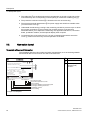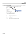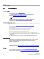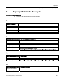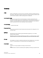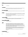
1
SITRANS Pressure transmitter SITRANS P500 Service Manual Edition 04/2013 Answers for industry. SITRANS P500 1 ___________________ Introduction 2 ___________________ Safety information SITRANS Pressure transmitter SITRANS P500 3 ___________________ Description 4 ___________________ Service and maintenance ___________________ 5 Dimension drawings Ordering data for spare ___________________ 6 parts/accessories Service Manual 7MF5**3 04/2013 A5E02344534-03 ___________________ A Appendix Legal information Warning notice system This manual contains notices you have to observe in order to ensure your personal safety, as well as to prevent damage to property. The notices referring to your personal safety are highlighted in the manual by a safety alert symbol, notices referring only to property damage have no safety alert symbol. These notices shown below are graded according to the degree of danger. DANGER indicates that death or severe personal injury will result if proper precautions are not taken. WARNING indicates that death or severe personal injury may result if proper precautions are not taken. CAUTION indicates that minor personal injury can result if proper precautions are not taken. NOTICE indicates that property damage can result if proper precautions are not taken. If more than one degree of danger is present, the warning notice representing the highest degree of danger will be used. A notice warning of injury to persons with a safety alert symbol may also include a warning relating to property damage. Qualified Personnel The product/system described in this documentation may be operated only by personnel qualified for the specific task in accordance with the relevant documentation, in particular its warning notices and safety instructions. Qualified personnel are those who, based on their training and experience, are capable of identifying risks and avoiding potential hazards when working with these products/systems. Proper use of Siemens products Note the following: WARNING Siemens products may only be used for the applications described in the catalog and in the relevant technical documentation. If products and components from other manufacturers are used, these must be recommended or approved by Siemens. Proper transport, storage, installation, assembly, commissioning, operation and maintenance are required to ensure that the products operate safely and without any problems. The permissible ambient conditions must be complied with. The information in the relevant documentation must be observed. Trademarks All names identified by ® are registered trademarks of Siemens AG. The remaining trademarks in this publication may be trademarks whose use by third parties for their own purposes could violate the rights of the owner. Disclaimer of Liability We have reviewed the contents of this publication to ensure consistency with the hardware and software described. Since variance cannot be precluded entirely, we cannot guarantee full consistency. However, the information in this publication is reviewed regularly and any necessary corrections are included in subsequent editions. Siemens AG Industry Sector Postfach 48 48 90026 NÜRNBERG GERMANY Order number: A5E02344534 Ⓟ 03/2013 Technical data subject to change Copyright © Siemens AG 2013. All rights reserved Table of contents 1 2 3 4 Introduction................................................................................................................................................ 5 1.1 Purpose of this documentation ......................................................................................................5 1.2 Product information........................................................................................................................5 1.3 History ............................................................................................................................................6 1.4 Purpose..........................................................................................................................................6 1.5 Checking the consignment.............................................................................................................7 1.6 Notes on warranty..........................................................................................................................7 Safety information...................................................................................................................................... 9 2.1 2.1.1 2.1.2 Precondition for use .......................................................................................................................9 Laws and directives .......................................................................................................................9 Conformity with European directives ...........................................................................................10 2.2 Improper device modifications .....................................................................................................10 2.3 Requirements for special applications .........................................................................................11 2.4 Use in hazardous areas ...............................................................................................................11 Description............................................................................................................................................... 15 3.1 Structure.......................................................................................................................................15 3.2 Nameplate layout .........................................................................................................................16 Service and maintenance ........................................................................................................................ 19 4.1 Basic safety instructions ..............................................................................................................19 4.2 4.2.1 4.2.2 4.2.3 4.2.4 4.2.4.1 4.2.4.2 4.2.4.3 4.2.4.4 4.2.4.5 4.2.4.6 Maintenance and repair work.......................................................................................................22 Defining the maintenance interval ...............................................................................................22 Checking the gaskets...................................................................................................................22 Changing the measuring cell and application electronics............................................................23 Replacing parts ............................................................................................................................24 Exploded view of the device ........................................................................................................24 Replacing the connection board ..................................................................................................25 Replacing the pushbutton module ...............................................................................................27 Replacing the display...................................................................................................................28 Replacing the application electronics ..........................................................................................30 Replacing the measuring cell.......................................................................................................32 4.3 4.3.1 Cleaning .......................................................................................................................................34 Servicing the remote seal measuring system ..............................................................................35 4.4 Return procedure .........................................................................................................................35 4.5 Disposal .......................................................................................................................................35 SITRANS P500 Service Manual, 04/2013, A5E02344534-03 3 Table of contents 5 Dimension drawings ................................................................................................................................ 37 5.1 SITRANS P500 for differential pressure, flow rate and absolute pressure from the differential pressure series .......................................................................................................... 37 5.2 SITRANS P500 for level.............................................................................................................. 38 6 Ordering data for spare parts/accessories ............................................................................................... 41 A Appendix.................................................................................................................................................. 43 A.1 Certificate .................................................................................................................................... 43 A.2 Literature and catalogs................................................................................................................ 43 A.3 Technical support........................................................................................................................ 44 A.4 Repair report for installation of spare parts................................................................................. 45 Glossary .................................................................................................................................................. 49 Index........................................................................................................................................................ 53 SITRANS P500 4 Service Manual, 04/2013, A5E02344534-03 Introduction 1.1 1 Purpose of this documentation These instructions contains all information that you will require to replace the connection board, pushbutton module, display, application electronics, and measuring cell of the device. For information about the safe usage of the device, refer to the detailed version of these instructions and corresponding safety instructions on the electronic data medium. Read these instructions carefully before you start any service and maintenance work. In order to use the device correctly, first make yourself acquainted with its principle of operation. Readership of these instructions are service and maintenance technicians. 1.2 Product information The programming manual is an integral part of the CD, which is either supplied or can be ordered. The programming manual is also available on the Siemens homepage. On the CD, you will also find the catalog extract with the ordering data, the Software Device Install for SIMATIC PDM for additional installation, and the required software. See also Product information on SITRANS P in the Internet (http://www.siemens.com/sitransp) Process instrumentation catalog (http://www.siemens.com/processinstrumentation/catalogs) SITRANS P500 Service Manual, 04/2013, A5E02344534-03 5 Introduction 1.3 History 1.3 History This history establishes the correlation between the current documentation and the valid firmware of the device. The documentation for this revision is applicable for the following firmware: Version Firmware and hardware identity nameplate System integration Installation path for PDM 02 09/201 0 FW: 35.01.00 PDM 6.01); Dev. R.3 DD; 01.00.00 Rev.1 SITRANSP500 03 04/201 3 FW: 35.02.00 PDM 6.01); Dev. R.3 DD; 01.00.00 Rev.1 SITRANSP500 1) 1.4 HW: 11.01.01 HW: 11.01.01 Note to SP05 Purpose Overview Depending on the variant, the pressure transmitter measures corrosive, non-corrosive and hazardous gases, vapors and liquids. With appropriate configuration, you can also use the differential pressure transmitter for the following measurement types: ● Level ● Volume ● Mass ● Volume flow ● Mass flow rate The output signal is always a load-independent direct current between 4 and 20 mA upon which a HART protocol is superimposed. You can install the "Intrinsically safe" or "Flameproof enclosure" version of the transmitter in hazardous areas. The devices have an EC type-examination certificate and meet the regulations applicable to them, for example, the harmonized CENELEC standards in Europe. Transmitters with remote seals of different shapes can be delivered for special applications. For example, measuring high-viscosity substances is a special application. Operate the device in accordance with the specifications in section Auto-Hotspot. For additional information, please refer to the operating instructions for the device. SITRANS P500 6 Service Manual, 04/2013, A5E02344534-03 Introduction 1.5 Checking the consignment 1.5 Checking the consignment 1. Check the packaging and the device for visible damage caused by inappropriate handling during shipping. 2. Report any claims for damages immediately to the shipping company. 3. Retain damaged parts for clarification. 4. Check the scope of delivery by comparing your order to the shipping documents for correctness and completeness. WARNING Using a damaged or incomplete device Danger of explosion in hazardous areas. Do not use damaged or incomplete devices. 1.6 Notes on warranty The contents of this manual shall not become part of or modify any prior or existing agreement, commitment or legal relationship. The sales contract contains all obligations on the part of Siemens AG as well as the complete and solely applicable warranty conditions. Any statements regarding device versions described in the manual do not create new warranties or modify the existing warranty. The content reflects the technical status at the time of publishing. Siemens reserves the right to make technical changes in the course of further development. SITRANS P500 Service Manual, 04/2013, A5E02344534-03 7 Introduction 1.6 Notes on warranty SITRANS P500 8 Service Manual, 04/2013, A5E02344534-03 Safety information 2.1 2 Precondition for use This device left the factory in good working condition. In order to maintain this status and to ensure safe operation of the device, observe these instructions and all the specifications relevant to safety. Observe the information and symbols on the device. Do not remove any information or symbols from the device. Always keep the information and symbols in a completely legible state. Symbol Explanation Consult operating instructions 2.1.1 Laws and directives Observe the test certification, provisions and laws applicable in your country during connection, assembly and operation. These include, for example: ● National Electrical Code (NEC - NFPA 70) (USA) ● Canadian Electrical Code (CEC) (Canada) Further provisions for hazardous area applications are for example: ● IEC 60079-14 (international) ● EN 60079-14 (EC) SITRANS P500 Service Manual, 04/2013, A5E02344534-03 9 Safety information 2.2 Improper device modifications 2.1.2 Conformity with European directives The CE mark on the device is a sign of conformity with the following European directives: Electromagnetic Compatibility EMC 2004/108/EC Directive of the European Parliament and of the Council on the approximation of the laws of the Member States relating to electromagnetic compatibility and repealing Directive 89/336/EEC. Atmosphère explosible ATEX 94/9/EC Directive of the European Parliament and the Council on the approximation of the laws of the Member States concerning equipment and protective systems intended for use in potentially explosive atmospheres. Pressure Equipment Directive PED 97/23/EC Directive of the European Parliament and of the Council on the approximation of the laws of the Member States concerning pressure equipment. The standards applied can be found in the EC declaration of conformity for the device. 2.2 Improper device modifications WARNING Improper device modifications Danger to personnel, system and environment can result from modifications to the device, particularly in hazardous areas. Only carry out modifications that are described in the instructions for the device. Failure to observe this requirement cancels the manufacturer's warranty and the product approvals. SITRANS P500 10 Service Manual, 04/2013, A5E02344534-03 Safety information 2.3 Requirements for special applications 2.3 Requirements for special applications Due to the large number of possible applications, each detail of the described device versions for each possible scenario during commissioning, operation, maintenance or operation in systems cannot be considered in the instructions. If you need additional information not covered by these instructions, contact your local Siemens office or company representative. Note Operation under special ambient conditions We highly recommend that you contact your Siemens representative or our application department before you operate the device under special ambient conditions as can be encountered in nuclear power plants or when the device is used for research and development purposes. 2.4 Use in hazardous areas Qualified personnel for hazardous area applications Persons who install, assemble, commission, operate and service the device in a hazardous area must have the following specific qualifications: ● They are authorized, trained or instructed in operating and maintaining devices and systems according to the safety regulations for electrical circuits, high pressures, aggressive and hazardous media. ● They are authorized, trained, or instructed in carrying out work on electrical circuits for hazardous systems. ● They are trained or instructed in maintenance and use of appropriate safety equipment according to the pertinent safety regulations. WARNING Unsuitable device for the hazardous area Danger of explosion. Only use equipment that is approved for use in the intended hazardous area and labelled accordingly. SITRANS P500 Service Manual, 04/2013, A5E02344534-03 11 Safety information 2.4 Use in hazardous areas WARNING Loss of the safety of the device with type of protection "Intrinsic safety Ex i" If the device has already been operated in non-intrinsically safe circuits or the information on the electrical specifications have been ignored, the safety of the device is no longer ensured for use in hazardous areas. There is a danger of explosion. Connect the device in Intrinsic Safety type of protection solely to an intrinsically safe circuit. Observe the information on the electrical specifications in the certificate and in the technical data. WARNING Use of incorrect device parts in potentially explosive environments Devices and their associated device parts are either approved for different types of protection or they do not have explosion protection. There is a danger of explosion if device parts (such as covers) are used for devices with explosion protection that are not expressly suited for this type of protection. If you do not adhere to these guidelines, the test certificates and the manufacturer warranty will become null and void. Use only device parts that have been approved for the respective type of protection in the potentially explosive environment. Covers that are not suited for the "explosionproof" type of protection are identified as such by a notice label attached to the inside of the cover with "Not Ex d Not SIL". Do not swap device parts unless the manufacturer specifically ensures compatibility of these parts. WARNING Risk of explosion due to electrostatic charge To prevent the build-up of an electrostatic charge in a hazardous area, the key cover must be closed during operation and the screws tightened. The key cover may be opened temporarily at any time for the purposes of operating the transmitter, even during plant operation; the screws should then be tightened again. SITRANS P500 12 Service Manual, 04/2013, A5E02344534-03 Safety information 2.4 Use in hazardous areas NOTICE Electrostatic-sensitive devices The device contains electrostatic-sensitive devices (ESD). ESD can be destroyed by voltages far too low to be detected by humans. These voltages can occur if you simply touch a component part or the electrical connections of a module without being electrostatically discharged. The damage to a module caused by overvoltage cannot normally be detected immediately; it only becomes apparent after a longer period of operating time has elapsed. Protective measures against the discharge of static electricity: Make sure that no power is applied. Before working with modules, make sure that you discharge static from your body, for example by touching a grounded object. Devices and tools used must be free of static charge. Hold modules only by their edges. Do not touch connector pins or conductor tracks on a module with the ESD notice. SITRANS P500 Service Manual, 04/2013, A5E02344534-03 13 Safety information 2.4 Use in hazardous areas SITRANS P500 14 Service Manual, 04/2013, A5E02344534-03 3 Description 3.1 Structure Depending on a customer-specific order, the device comprises different parts. ① ② ③ ④ ⑤ ⑥ ⑦ Approval plate Safety latch Blanking plug Keys cover Cover (front), optionally with an inspection window Display (optional) Measuring point label Figure 3-1 ⑧ ⑨ ⑩ ⑪ ⑫ ⑬ ⑭ Measuring cell with process flanges Cable inlet, optional with cable gland Electrical terminal compartment Cover (rear) for electrical terminal compartment Protective conductor connection Nameplate Retaining screws (both sides), twist proofing of the measuring cell in relation to the electronics enclosure Device view of the transmitter ● The electronic enclosure is made of aluminum die casting. ● The enclosure has a removable circular cover at the front and the back. ● Depending on the device version, the cover ⑤ is provided with an inspection window. Through the inspection window, the measured values can be read from the display (optional) ⑥. ● The user must not use the service connector located behind the display ⑥. The service plug is for the exclusive use of the manufacturer. SITRANS P500 Service Manual, 04/2013, A5E02344534-03 15 Description 3.2 Nameplate layout ● The cable inlet ⑨ to the electrical terminal compartment on the left or right side can be used selectively. The corresponding unused opening is closed with a blanking plug ③. ● The protective conductor terminal ⑫ is located on the rear of the housing. ● The electrical terminal compartment ⑩ for power supply and shield is accessible when you unscrew the cover ⑪. ● Underneath the electronics housing is the measuring cell with its pressure caps on which the process connections ⑧ are located. The modular structure of the pressure transmitter allows you to replace the measuring cell, application electronics, connection board, pushbutton module, and the optional display when required. ● On the upper face of the enclosure you can see crosshead screws which secure the cover ④, under which the 3 keys for local operation are located. 3.2 Nameplate layout Nameplate with general information The nameplate with the order number and other important data, such as the design details and technical data can be found on the side of the enclosure. SITRANS P500 PED/SEP 0045 Transmitter for differential pressure 7MF5603-1DA00-0AD1-Z +E00 F.-Nr. B1-F908-9000001 HW: 01.01.00 / FW: 35.00.1 0 ① Order number ② Serial number ③ Firmware (FW) and hardware (HW) numbers V H : DC 10.6-44 V (non IS) 4- 20 mA HART Mat.: Connec. Diaphr. O-ring Filling 1. 4404 1. 4404 FKM (FPM) Silicone oil Measuring span : 31.25 - 6250 mbar Rated pressure : PN 160 Schutzart IP 66/68 twistlock screw made in France SIEMENS AG D-76181 Karlsruhe +:DDEEFF ):DDEEFF ):FKDQJHFRXQWHU ):IXQFWLRQH[SDQVLRQFRXQWHU 'HYLFHPDUNLQJ +:FKDQJHVDIIHFWLQJPHFKDQLFDOV\VWHP +:FKDQJHVDIIHFWLQJHOHFWURQLFV &RPSDWLELOLW\FRXQWHU 'HYLFHPDUNLQJ Example of a nameplate SITRANS P500 16 Service Manual, 04/2013, A5E02344534-03 Description 3.2 Nameplate layout Nameplate with approval information The nameplate with approval information is on the opposite side. For the Ex-version of the transmitter, the information on the respective certificate is also listed. SITRANS P500 II 1/2 G Ex d ia IIC T4/T6 Ta : -40...+85°C (-40...+185°F) Temperature class T4 Ta : -40...+60°C (-40...+140°F) Temperature class T6 U = 45V ,,*([GLD,,&77 BVS 09 ATEX E 027 Observe EC-Type Examination Certificate ! D SIEMENS AG D-76181 Karlsruhe Figure 3-2 ① ①a ①b ①c ①d E F G twistlock screw Example of a nameplate Characteristics of the hazardous area Category of the operating range Type of protection Group (gas, dust) Maximum surface temperature (temperature class) SITRANS P500 Service Manual, 04/2013, A5E02344534-03 17 Service and maintenance 4.1 4 Basic safety instructions WARNING Impermissible repair of explosion protected devices Danger of explosion in areas subject to explosion hazard. Repair must be carried out by Siemens authorized personnel only. WARNING Impermissible accessories and spare parts Danger of explosion in areas subject to explosion hazard. Only use original accessories or original spare parts. Observe all relevant installation and safety instructions described in the instructions for the device or enclosed with the accessory or spare part. WARNING Use of incorrect device parts in potentially explosive environments Devices and their associated device parts are either approved for different types of protection or they do not have explosion protection. There is a danger of explosion if device parts (such as covers) are used for devices with explosion protection that are not expressly suited for this type of protection. If you do not adhere to these guidelines, the test certificates and the manufacturer warranty will become null and void. Use only device parts that have been approved for the respective type of protection in the potentially explosive environment. Covers that are not suited for the "explosionproof" type of protection are identified as such by a notice label attached to the inside of the cover with "Not Ex d Not SIL". Do not swap device parts unless the manufacturer specifically ensures compatibility of these parts. SITRANS P500 Service Manual, 04/2013, A5E02344534-03 19 Service and maintenance 4.1 Basic safety instructions WARNING Maintenance during continued operation in a hazardous area There is a danger of explosion when carrying out repairs and maintenance on the device in a hazardous area. Isolate the device from power. - or Ensure that the atmosphere is explosion-free (hot work permit). WARNING Commissioning and operation with pending error If an error message appears, correct operation in the process is no longer guaranteed. Check the gravity of the error Correct the error If the error still exists: – Take the device out of operation. – Prevent renewed commissioning. WARNING Hot, toxic or corrosive process media Danger of injury during maintenance work. When working on the process connection, hot, toxic or corrosive process media could be released. As long as the device is under pressure, do not loosen process connections and do not remove any parts that are pressurized. Before opening or removing the device ensure that process media cannot be released. WARNING Improper connection after maintenance Danger of explosion in areas subject to explosion hazard or device damage. Connect the device correctly after maintenance. Close the device after maintenance work. See Operating Instructions. SITRANS P500 20 Service Manual, 04/2013, A5E02344534-03 Service and maintenance 4.1 Basic safety instructions WARNING Use of a computer in a hazardous area If the interface to the computer is used in the hazardous area, there is a danger of explosion. Ensure that the atmosphere is explosion-free (hot work permit). CAUTION Releasing key lock Improper modification of parameters could influence process safety. Make sure that only authorized personnel may cancel the key locking of devices for safety-related applications. CAUTION Hot surfaces Danger of burns during maintenance work on parts having surface temperatures exceeding 70 °C (158 °F). Take corresponding protective measures, for example by wearing protective gloves. After carrying out maintenance, remount touch protection measures. NOTICE Electrostatic-sensitive devices The device contains electrostatic-sensitive devices (ESD). ESD can be destroyed by voltages far too low to be detected by humans. These voltages can occur if you simply touch a component part or the electrical connections of a module without being electrostatically discharged. The damage to a module caused by overvoltage cannot normally be detected immediately; it only becomes apparent after a longer period of operating time has elapsed. Protective measures against the discharge of static electricity: Make sure that no power is applied. Before working with modules, make sure that you discharge static from your body, for example by touching a grounded object. Devices and tools used must be free of static charge. Hold modules only by their edges. Do not touch connector pins or conductor tracks on a module with the ESD notice. SITRANS P500 Service Manual, 04/2013, A5E02344534-03 21 Service and maintenance 4.2 Maintenance and repair work 4.2 Maintenance and repair work 4.2.1 Defining the maintenance interval WARNING No maintenance interval has been defined Device failure, device damage, and risk of injury. Define a maintenance interval for regular tests in line with device use and empirical values. The maintenance interval will vary from site to site depending on corrosion resistance. 4.2.2 Checking the gaskets Note Checking the gaskets At regular intervals, check that the enclosure seals of the pressure transmitter satisfy IP66 / IP68. Grease or replace the gaskets if required. SITRANS P500 22 Service Manual, 04/2013, A5E02344534-03 Service and maintenance 4.2 Maintenance and repair work 4.2.3 Changing the measuring cell and application electronics Related Each of the individual components "Measuring cell" and "Electronics" has a non-volatile memory (EEPROM). Measuring cell data (e.g.: measuring range, measuring cell material, oil filling) and application-specific electronics data (e.g.: downscaling, additional electrical damping) are located in the measuring cell EEPROM. Application-specific data are lost when the measuring cell is changed. Application-specific data are not lost when the application electronics are changed. You can backup application-specific data before changing the measuring cell and reload them afterwards. Use an input device which supports the HART protocol. (e.g. HART communicator, PC with HART modem and HART software or PC with HART modem and PDM software). Factory settings will be used if application-specific data are not backed up before the measuring cell is changed. Technical developments enable advanced functions to be implemented in the firmware of the measuring cell or application electronics. Further technical developments are indicated by modified firmware statuses (FW). The firmware status does not affect whether the modules can be replaced. However, the scope of functions is limited to the function of existing components. If a combination of certain firmware versions of measuring cell and application electronics is not possible for technical reasons, the device will identify this problem and go into "Fault current" mode. This information is provided via the HART interface. SITRANS P500 Service Manual, 04/2013, A5E02344534-03 23 Service and maintenance 4.2 Maintenance and repair work 4.2.4 Replacing parts 4.2.4.1 Exploded view of the device The device consists of different components, depending on the customer's order. The next chapters show you how to replace the components. ① ② ③ ④ ⑤ Measuring cell with process flanges Sealing ring between the measuring cell and housing Cover (rear) for electronic terminal compartment Sealing ring between the cover and housing Connection board Figure 4-1 ⑥ ⑦ Pushbutton module ⑧ ⑨ ⑩ Application electronics Housing Display (optional) Cover (front), optionally with inspection window Exploded view of the transmitter SITRANS P500 24 Service Manual, 04/2013, A5E02344534-03 Service and maintenance 4.2 Maintenance and repair work 4.2.4.2 Replacing the connection board Procedure for replacing the connection board 1. Isolate the device from power. 2. Open the cover of the electronic connection compartment. 3. Disconnect the cables from the connection board. SITRANS P500 Service Manual, 04/2013, A5E02344534-03 25 Service and maintenance 4.2 Maintenance and repair work 4. On the left and right side, remove the recessed-head screws that hold the connection board to the enclosure. 5. Remove the connection board. To install the connection board, proceed as follows 1. Insert the new connection board so that its contact pins on rear side mate the contacts in the housing. SITRANS P500 26 Service Manual, 04/2013, A5E02344534-03 Service and maintenance 4.2 Maintenance and repair work 2. Work in the reverse order as described in "Procedure for replacing the connection board". See also Structure (Page 15) Exploded view of the device (Page 24) 4.2.4.3 Replacing the pushbutton module Procedure 1. Isolate the device from power. 2. To open the pushbutton cover, remove both recessed-head screws from the outside of the cover. SITRANS P500 Service Manual, 04/2013, A5E02344534-03 27 Service and maintenance 4.2 Maintenance and repair work 3. Using a TX9 torx screwdriver, remove the three screws you can now see. 4. Remove the pushbutton module from the housing. 5. To install the new pushbutton module, carry out the same steps in the reverse order. 6. When inserting the new pushbutton module, make sure that the seals are sitting properly. See also Structure (Page 15) Exploded view of the device (Page 24) 4.2.4.4 Replacing the display Procedure for replacing the display 1. Open the front cover (optional with inspection window). SITRANS P500 28 Service Manual, 04/2013, A5E02344534-03 Service and maintenance 4.2 Maintenance and repair work 2. Remove the recessed-head screws on the left and right side. 3. Pull the display out of the housing. SITRANS P500 Service Manual, 04/2013, A5E02344534-03 29 Service and maintenance 4.2 Maintenance and repair work Procedure for installing the display 1. Insert the new display so that the the contact pins on its rear side mate the socket strip. 2. You can also turn the mounting position of the display by 90 °, 180 °, or 270 °. 3. Work in the reverse order as described in "Procedure for replacing the display". See also Structure (Page 15) Exploded view of the device (Page 24) 4.2.4.5 Replacing the application electronics Procedure for replacing the application electronics 1. Isolate the device from power. 2. Open the front cover of the display (optional with inspection window). 3. Remove the display. See Section Replacing the display (Page 28). 4. Using an 8 mm socket wrench, remove the hexagon nuts from the left and right side. SITRANS P500 30 Service Manual, 04/2013, A5E02344534-03 Service and maintenance 4.2 Maintenance and repair work 5. Remove the application electronics. 6. Disconnect the ribbon cable from the application electronics. Procedure for installing the application electronics 1. Connect the ribbon cable to the application electronics so that the coding notch of the connector faces upward. Compare the corresponding marking on the application electronics with the photo image. 2. Do not kink, pinch, or twist the ribbon cable when plugging it onto the application electronics. 3. Work in the reverse order as described in "Procedure for replacing the application electronics". SITRANS P500 Service Manual, 04/2013, A5E02344534-03 31 Service and maintenance 4.2 Maintenance and repair work See also Structure (Page 15) Exploded view of the device (Page 24) 4.2.4.6 Replacing the measuring cell Procedure 1. Isolate the device from power. 2. Open the display cover (optional with inspection window). 3. Remove the display. See Section Replacing the display (Page 28). 4. Remove the application electronics. See Section Replacing the application electronics (Page 30). 5. Using a hexagonal socket wrench size 2.5 mm, remove the lock screws from both sides of the housing. 6. Turn the measuring cell clockwise by a small distance so that you can access the screws underneath the housing. SITRANS P500 32 Service Manual, 04/2013, A5E02344534-03 Service and maintenance 4.2 Maintenance and repair work 7. Using a TX20 torx screwdriver, remove both screws from the bottom of the housing. NOTICE Damage to the ribbon cable To avoid damage to the ribbon cable when installing or removing the measuring cell, do not kink, pinch, or twist it. Do not kink, pinch, or twist the ribbon cable. 8. Turn the measuring cell counter-clockwise to remove it from the housing. 1. To install the new measuring cell, carry out the same steps in the reverse order. See also Structure (Page 15) Exploded view of the device (Page 24) SITRANS P500 Service Manual, 04/2013, A5E02344534-03 33 Service and maintenance 4.3 Cleaning 4.3 Cleaning WARNING Dust layers above 5 mm Danger of explosion in hazardous areas. Device may overheat du to dust build up. Remove any dust layers in excess of 5 mm. NOTICE Penetration of moisture into the device Device damage. Make sure when carrying out cleaning and maintenance work that no moisture penetrates the inside of the device. Cleaning the enclosure ● Clean the outside of the enclosure and the display window using a cloth moistened with water or a mild detergent. ● Do not use aggressive cleaning agents or solvents. Plastic components or painted surfaces could be damaged. WARNING Electrostatic charge Danger of explosion in hazardous areas if electrostatic charges develop, for example, when cleaning plastic enclosures with a dry cloth. Prevent electrostatic charging in hazardous areas. SITRANS P500 34 Service Manual, 04/2013, A5E02344534-03 Service and maintenance 4.4 Return procedure 4.3.1 Servicing the remote seal measuring system The remote seal measuring system usually does not need servicing. If the mediums are contaminated, viscous or crystallized, it could be necessary to clean the diaphragm from time to time. Use only a soft brush and a suitable solvent to remove the deposits from the diaphragm. Do not use corrosive cleaning agents. Prevent the diaphragm from getting damaged due to sharp-edged tools. NOTICE Improper cleaning of diaphragm Device damage. The diaphragm can be damaged. Do not use sharp or hard objects to clean the diaphragm. 4.4 Return procedure Enclose the bill of lading, return document and decontamination certificate in a clear plastic pouch and attach it firmly to the outside of the packaging. Any devices/replacement parts which are returned without a decontamination declaration will be cleaned at your expense before further processing. For further details refer to the operating instructions. 4.5 Disposal Devices identified by this symbol may not be disposed of in the municipal waste disposal services under observance of the Directive 2002/96/EC on waste electronic and electrical equipment (WEEE). They can be returned to the supplier within the EC or to a locally approved disposal service. Observe the specific regulations valid in your country. Note Special disposal required The device includes components that require special disposal. Dispose of the device properly and environmentally through a local waste disposal contractor. SITRANS P500 Service Manual, 04/2013, A5E02344534-03 35 Service and maintenance 4.5 Disposal SITRANS P500 36 Service Manual, 04/2013, A5E02344534-03 5 Dimension drawings 5.1 SITRANS P500 for differential pressure, flow rate and absolute pressure from the differential pressure series FD FD FD FD FD FD ① ② ③ ④ ⑤ ⑥ ⑦ ⑧ ⑨ ⑩ Electronics side, display Connection side Keys cover Electrical connection: Screw gland M20 x 1.5 or 1/2-14 NPT Han 7D/Han 8U plug2)3) or M123) Han 7D/Han 8D plug2) 3) Mounting bracket (optional) Electrical connection: Process connection, with valve (optional) or screwed joint (optional) Screw lid - safety bracket Screw-type blank cap Process connection: 1/4-18 NPT (IEC 61518) 1) In addition, allow approx. 20 mm (0.79 inch) for the thread length 2) Not with "Explosion-proof" type of protection 3) Not for "FM + CSA [is + XP]" type of protection Figure 5-1 SITRANS P500 pressure transmitter for differential pressure and flow rate, measurements in mm (inch): Order No.: 7MF54** SITRANS P500 Service Manual, 04/2013, A5E02344534-03 37 Dimension drawings 5.2 SITRANS P500 for level 5.2 SITRANS P500 for level FD FD / G G N ' QG I E ① ② ③ ④ ⑤ ⑥ ⑦ Electrical connection: Screw gland M20 x 1.53) or 1/2-14 NPT Han 7D/Han 8D plug2)3) or M12 Keys cover Screw-type blank cap Connection side Electronics side, display Process connection, negative side with valve (optional) or screw gland (optional) Screw lid - safety bracket SITRANS P500 38 Service Manual, 04/2013, A5E02344534-03 Dimension drawings 5.2 SITRANS P500 for level ⑧ ⑨ ⑩ ⑪ 1) Process connection: Negative side 1/4-18 NPT (IEC 61518) Electrical connection: Han 7D/Han 8D plug2) 3) Mounting flange as per EN1092-1 or ASME B16.5 Free space for turning housing In addition, allow approx. 20 mm (0.79 inch) for the thread length 2) Not with "Explosion-proof" type of protection 3) Not for "FM + CSA [is + XP]" type of protection Figure 5-2 SITRANS P500 pressure transmitter for level, including mounting flange, measurements in mm (inch): Order No.: 7MF56** SITRANS P500 Service Manual, 04/2013, A5E02344534-03 39 Ordering data for spare parts/accessories Selection and ordering data Order No. Replacement measuring cells for differential pressure SITRANS P pressure transmitters for differential pressure and flow, P500 HART PN 160 series (MAWP 2320 psi) 7MF 5 9 9 4 - Measuring cell filling Silicone oil Measuring cell cleaning normal 6 1 1 Measuring span (min. ... max.) 1,25 ... 250 mbar (0.5 ... 100.4 inH2O) 6,25 ... 1250 mbar (2.5 ... 502 inH2O) 31,25 ... 6250 mbar (12.54 ... 2509 inH2O) 0,16 ... 32 bar (2.33 ... 465 psi) D E F G Wetted parts materials (stainless steel process flanges) Seal diaphragm Parts of measuring cell Stainless steel 1.4404/316L Stainless steel 1.4404/316L A Hastelloy C276 Stainless steel1.4404/316L B Monel 400 Stainless steel1.4404/316L C Process connection Female thread ¼-18 NPT • Sealing screw opposite process connection - Mounting thread 7/16-20 UNF to IEC 61518 - Mounting thread M10 to DIN 19213 • Vent on side of process flange - Mounting thread 7/16-20 UNF to IEC 61518 - Mounting thread M10 to DIN 19213 Further designs 0 1 4 5 Order code Add "-Z" to Order No. and specify Order Code. Acceptance test certificate Acc. to EN 10204-3.1 C12 Without process flanges K00 Vent on side for gas measurements1) L32 Process flanges, O-ring, special material Standard: Viton (FKM (FPM)) Process connection sealing rings made of PTFE (Teflon), virginal L60 Process connection sealing rings made of PTFE (Teflon), glass fiber-reinforced L61 Process connection sealing rings made of FFPM (Kalrez) L62 Process flanges, O-rings made of NBR L63 Process flanges, O-rings made of graphite L64 1) Only in conjunction with process connection code 4 or 5. SITRANS P500 Service Manual, 04/2013, A5E02344534-03 41 Ordering data for spare parts/accessories Selection and Ordering data Selection and Ordering data Order No. Mounting brackets For differential pressure transmitters with flange thread M10 (7MF54..-…10 and 7MF54..-…50) • Made of steel • Made of stainless steel Mounting brackets for differential pressure transmitter with flange thread 7/16-20 UNF (7MF54..-…00 and 7MF54..-…40) • Made of steel • Made of stainless steel 7MF5987-1AA 7MF5987-1AD Digital indicator Including mounting material German A5E02344527 English A5E02344528 French A5E02344529 Italian A5E02344530 Spanish A5E02344531 Compact operating instructions1) 7MF5987-1AC 7MF5987-1AF Cover Made of die-cast aluminum, including O-ring • Without window • With window Order No. Operating Instructions1) 7MF5987-1BE 7MF5987-1BF 7MF5987-1BR TAG plate (incl. fastening material) English, German, Spanish, French, Italian, Dutch A5E02344532 English, Estonian, Latviaan, Lithuanian, Polish, Romanian A5E02307339 English, Bulgarian, Czech, Finnish, Slovakian, Slovenian A5E02307340 English, Danish, Greek, Portuguese, Swedish, Hungarian A5E02307341 Russian A5E02307338 Brief instructions (Leporello) Without inscription (5 pcs.) 7MF5987-1CA German, English A5E02344536 Printed (1 pc.) Data according to Y01 or Y02, Y15 and Y16 (see "SITRANS P transmitters") 7MF5987-1CB-Z Y..: ...................... French, English A5E02344537 Italian, English A5E02344538 Spanish, English A5E02344539 Chinese, English A5E02344540 Russian, English A5E02556625 Mounting screws For TAG plate, grounding and connection terminals and securing and locking screws (30 units) Sealing plugs for process flange (1 set = 2 units) • Made of stainless steel • Made of Hastelloy Vent valve Complete (1 set = 2 units) • Made of stainless steel • Made of Hastelloy 7MF5987-1CC DVD withSITRANS Pdocumentation 7MF4997-1CG 7MF4997-1CH 7MF4997-1CP 7MF4997-1CQ Electronics module HART, intrinsically safe Ex ia for installation in transmitter casing (observe warranty conditions) 7MF5987-1DC Connection board (incl. fastening material) HART, intrinsically safe Ex ia for installation in transmitter casing (observe warranty conditions) O-rings for process flanges made of: • Viton (FKM (FPM)) (10 pcs.) • NBR (Buna N) (10 pcs.) Push buttons assembly (incl. fastening material) 7MF5987-1DM • NBR sealing ring for screw cover (10 pcs.) • NBR sealing ring for interface measuring cell/housing (10 pcs.) Service Instructions1) for replacement of electronics, measuring cell and terminal board • German • English A5E02344535 A5E02822443 A5E02344534 HART modem • With RS232 interface 7MF4997-1DA • With USB interface 7MF4997-1DB Operating instruction1) Supplementary electronics for 4-wire connection German, English A5E00322799 Certificates (order only via SAP) additional to internet download 7MF5987-2DA 7MF5987-2DE • Hard copy (to order) A5E03252406 7MF5987-2AF • On CD (to order) A5E03252407 1) For replacement of operating keys for onsite operation of the transmitter Sealing ring for • Process connection German, English, French, Spanish, Italian Compact operating instructions in 21 EU languages You can download these operating instructions free-of-charge from our Internet site at www.siemens.com/sitransp. Available ex stock. See catalog FI01, "Fittings" 7MF4997-2EA 7MF5987-2EB For power supply units, see catalog FI01 "Supplementary Compontents". SITRANS P500 42 Service Manual, 04/2013, A5E02344534-03 A Appendix A.1 Certificate The certificates can be found on the enclosed CD and on the Internet under: Certificates (http://www.siemens.com/processinstrumentation/certificates) A.2 Literature and catalogs No. Title Publisher Order no. /1/ Catalog ST 70 SIMATIC Products for Totally Integrated Automation Siemens AG E86060-K4670-A111-B1 /2/ Catalog ST 70 N SIMATIC News Products for Totally Integrated Automation Siemens AG E86060-K4670-A151-A3 /3/ Catalog ST 80 SIMATIC HMI operation and observation products Siemens AG E86060-K4680-A101-B4 /4/ Catalog IK PI Industrial Communication Siemens AG Internet address: IK PI catalog (http://www.automation.siemens.com/net/ html_76/support/printkatalog.htm) E86060-K6710-A101-B5 /5/ Catalog FI 01 Field devices for process automation Siemens AG E86060-K6201-A101-B1 /6/ Catalog CA 01 The interactive catalog of Industry Automation and Drive Technologies Siemens AG E86060-D4001-A500-C7 (DVD) SITRANS P500 Service Manual, 04/2013, A5E02344534-03 43 Appendix A.3 Technical support A.3 Technical support Technical Support You can contact Technical Support for all IA and DT products: ● Via the Internet using the Support Request: Support request (http://www.siemens.com/automation/support-request) ● E-mail (mailto:[email protected]) ● Phone: +49 (0) 911 895 7 222 ● Fax: +49 (0) 911 895 7 223 Further information about our technical support is available on the Internet at Technical Support (http://www.siemens.com/automation/csi/service) Service & Support on the Internet In addition to our documentation, we offer a comprehensive knowledge base on the Internet at: Services & Support (http://www.siemens.com/automation/service&support) There you will find: ● The latest product information, FAQs, downloads, tips and tricks. ● Our newsletter with the latest information about our products. ● A Knowledge Manager to find the right documents for you. ● Our bulletin board, where users and specialists share their knowledge worldwide. ● Your local contact partner for Industry Automation and Drives Technologies in our partner database. ● Information about field service, repairs, spare parts and lots more under "Services." Additional Support Please contact your local Siemens representative and offices if you have any questions about the products described in this manual and do not find the right answers. Find your contact partner at: Partner (http://www.automation.siemens.com/partner) Documentation for various products and systems is available at: Instructions and manuals (http://www.siemens.com/processinstrumentation/documentation) See also Product information on SITRANS P in the Internet (http://www.siemens.com/sitransp) Process instrumentation catalog (http://www.siemens.com/processinstrumentation/catalogs) SITRANS P500 44 Service Manual, 04/2013, A5E02344534-03 Appendix A.4 Repair report for installation of spare parts A.4 Repair report for installation of spare parts For your local documentation ● Check mark the relevant items and fill out the fields 1. Customer information: Company: Address: Department: Tel / Fax: E-mail: System part: 2. Information on the original device: first replacement of a component ⃞ Electronic serial number: Sensor serial number: F-no.: (rating plate) HW: Approval plate) FW: (approval plate) Device order no.: 7MF5 _ _ _ _ - _ _ _ _ _ - _ _ _ _ - Z _ _ _ Additional components -Z___-Z___-Z___-Z___-Z___-Z___-Z___-Z___-Z___-Z___ 3a. Device information Spare Part(1): Measuring cell Sensor serial number: Spare part order no.: 7MF599 _ - _ _ _ _ _ _ - Z _ _ _ Additional components -Z___-Z___-Z___-Z___-Z___-Z___-Z___-Z___-Z___-Z___ 3b. Device information Spare Part(2): Application electronics Electronic serial number: ES: (electronic cup) SITRANS P500 Service Manual, 04/2013, A5E02344534-03 45 Appendix A.4 Repair report for installation of spare parts Device information Spare Part(2): Application electronics FW: (electronic cup) Spare part order no.: 7MF5999 - _ _ _ _ _ - _ _ _ _ 3c. Device information Spare Part(3): Connection board HW: (connection board) Spare part order no.: 7MF5999 - _ _ _ _ _ - _ _ _ _ 3d. Device information Spare Part(4): Pushbutton module HW: (connection board) Spare part order no.: 7MF5999 - _ _ _ _ _ - _ _ _ _ 3e. Device information Spare Part(5): Display HW: (connection board) Spare part order no.: 7MF5999 - _ _ _ _ _ - _ _ _ _ 3f. Device information Spare Part(6): Additional spare parts HW: (connection board) Spare part order no.: 7MF5999 - _ _ _ _ _ - _ _ _ _ 4. Additional information Installation location (precise definition) SITRANS P500 46 Service Manual, 04/2013, A5E02344534-03 Appendix A.4 Repair report for installation of spare parts Additional information Repair period: From: To Safety measures: Work completed: 5. Acceptance: Check mark the relevant items and fill out the fields Replacement documentation was read and observed: ⃞ ESD guidelines were observed: ⃞ Inspected by Ex expert: ⃞ Function test completed: ⃞ Name of Ex expert: Date: Signature of Ex expert: Author name: Date: Author signature: SITRANS P500 Service Manual, 04/2013, A5E02344534-03 47 Appendix A.4 Repair report for installation of spare parts SITRANS P500 48 Service Manual, 04/2013, A5E02344534-03 Glossary ATEX ATEX is an abbreviation of the French term "Atmosphère explosible" (potentially explosive atmosphere). ATEX stands for both EC directives in the area of explosion protection: ATEX product directive 94/9/EC and ATEX operating directive 1999/92/EC. Auxiliary power supply Auxiliary power supply refers to an electrical supply or reference voltage which some electrical circuits require apart from the standard supply. The auxiliary power supply can, for example, be specially stabilized, have a particular level or polarity and/or other properties which are important for the correct functioning of switch components. Auxiliary voltage → Auxiliary power supply Dangerous failure Failure with the potential to bring the safety-instrumented system into a dangerous or nonfunctional status. EEPROM EEPROM (Electrically Erasable Programmable Read-Only Memory): a non-volatile, electronic memory module. EEPROMs are often used where individual bytes of data (e.g. configuration data or runtime meters) change over time and must be stored safely in the event of a mains power failure. Fail-safe The capability of a control to maintain the safe state of the controlled device, e.g. machine, process, or to bring the device to a safe state even when faults/failures occur. Failure/Fault Failure: A resource is no longer capable of executing a required function. Fault: Undesired state of a resource indicated by the incapability of executing a required function. SITRANS P500 Service Manual, 04/2013, A5E02344534-03 49 Glossary Fault → Failure/Fault Fault tolerance Fault tolerance N means that a device can execute the intended task even when N faults exist. The device fails to execute the intended function in case of N+1 faults. Final controlling element Converter that converts electrical signals into mechanical or other non-electrical variables. Firmware Firmware (FW) is software that is embedded on a chip in electronic devices – in contrast to software which is saved on hard disks, CD-ROMs or other media. These days, firmware is mostly stored in a flash memory or EEPROM. Firmware usually contains the elementary functions for controlling the device, as well as input and output routines. Frequency shift keying Frequency shift keying is a simple form of modulation, where the digital values 0 and 1 modulate the actual current signal by means of two different frequencies. Frequency Shift Keying (FSK) → Frequency shift keying HART HART (Highway Addressable Remote Transducer) is a standardized, widely used communications system used to structure industrial fieldbusses. The communications system provides digital communications for multiple participants (field devices) via a common databus. HART is based especially on the equally widely used 4/20 mA standard for the transfer of analog sensor signals. The cabling from existing older systems can be used directly and both systems operated in parallel. HART specifies several protocol levels in the OSI model. It facilitates the transfer of process and diagnostics data and control signals between field devices and high-level control systems. Standardized parameter sets can be used for the manufacture-independent operation of all HART devices. Typical applications include transmitters for measuring mechanical and electrical dimensions. Non-volatile memory → EEPROM SITRANS P500 50 Service Manual, 04/2013, A5E02344534-03 Glossary Risk The combination of probability of a damage occurring and its magnitude. Safety function Defined function executed by a safety-instrumented system with the objective of achieving or maintaining a safe system status taking into account a defined dangerous occurrence. Example: Limit pressure monitoring Safety Instrumented Function → SIF Safety Integrity Level → SIL Safety-instrumented system A safety-instrumented system executes the safety functions that are required to achieve or maintain a safe status in a system. It consists of a sensor, logic unit/control system and final controlling element. Example: A safety-instrumented system is made up of a pressure transmitter, a limit signal sensor and a control valve. Sensor Converter that converts mechanical or other non-electrical variables into electrical signals. SIF A part/function of a safety-instrumented system that reduces the risk of a dangerous failure occurring. SITRANS P500 Service Manual, 04/2013, A5E02344534-03 51 Glossary SIL The international standard IEC 61508 defines four discrete Safety Integrity Levels (SIL) from SIL 1 to SIL 4. Each level corresponds to the probability range for the failure of a safety function. The higher the SIL of the safety-instrumented system, the higher probability that the required safety function will work. The achievable SIL is determined by the following safety characteristics: ● Average probability of dangerous failure of a safety function in case of demand (PFDAVG) ● Hardware fault tolerance (HFT) ● Safe failure fractions (SFF) Total error Total Error is sum of Total Performance and the long-term stability. Total Error(s) → Total error Total Performance Total Performance is the square root of the sum of the squares of the three deviations resulting from the influence of the static pressure, the temperature and the characteristic deviation. TP → Total Performance SITRANS P500 52 Service Manual, 04/2013, A5E02344534-03 Index A Q Qualified personnel, 11 Additional Support, 44 C Certificate, 43 Certificates, 9 Certification, 43 Correct usage, 10 Customer Support Hotline, 44 D Device Electrostatic-sensitive, 21 E R Remote seal Maintenance, 35 S Scope of delivery, 7 Service, 44 Structure, 15 Support, 44 T Test certificates, 9 Electrostatic-sensitive device (ESD), 21 F Firmware, 6 H Hazardous area Laws and directives, 9 History, 6 Hotline, 44 I Improper device modifications, 10 Internet, 44 P Process connection, 16 SITRANS P500 Service Manual, 04/2013, A5E02344534-03 53 Get more information www.siemens.com/processautomation www.siemens.com/sitransp Siemens AG Industry Sector Postfach 48 48 90026 NÜRNBERG GERMANY Subject to change without prior notice A5E02344534-03 © Siemens AG 2013 A5E02344534 A5E02344534 www.siemens.com/automation