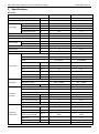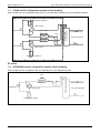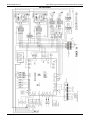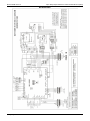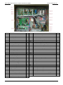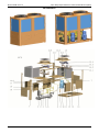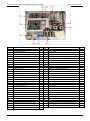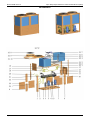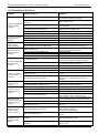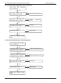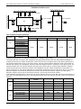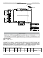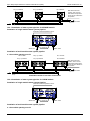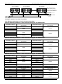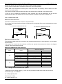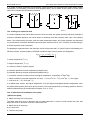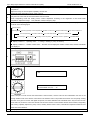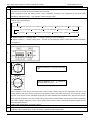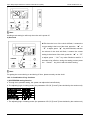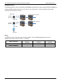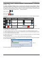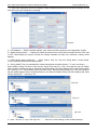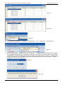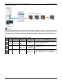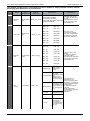
1
Midea Commercial Air Conditioner R410A Air-cooled Scroll Chiller Technical Service Manual (380-415V ~3Ph ~50Hz) MCAC-ATSM-2014-10 Aqua Tempo Super Series air cooled scroll chiller unit (50Hz) Content 1.Nomenclature ..............................................................................................................................2 2.Product Lineup .............................................................................................................................2 3. External Appearance ...................................................................................................................3 4.Features .......................................................................................................................................4 5.Specifications ...............................................................................................................................9 6.Dimensions ................................................................................................................................ 17 7.Refrigeration System Sketch Drawing ......................................................................................... 20 8.Wiring Diagrams.........................................................................................................................22 9.Electric Characteristics ................................................................................................................36 10.Capacity Tables ......................................................................................................................... 37 11.Exploded View ......................................................................................................................... 55 12.Trouble Shooting ......................................................................................................................77 13.Installation ...............................................................................................................................89 13.1 Unit Installation ................................................................................................................................. 89 13.2 Water System Installation .................................................................................................................. 92 13.3 Wiring Installation ........................................................................................................................... 102 14.Commissioning ....................................................................................................................... 106 15.Maintenance .......................................................................................................................... 107 16.Control System ....................................................................................................................... 109 16.1 PCB Outline and Description ............................................................................................................ 109 16.2 Wired Controller KJRM-120D/BMK-E(Standard) ............................................................................... 121 16.3 Wired controller KJR-120A/MBTE(Optional) ..................................................................................... 131 16.4 Control software .............................................................................................................................. 140 16.5 Lonworks gateway (Optional) ........................................................................................................... 160 17. Optional Accessories ................................................................................................................ 168 Appendix ....................................................................................................................................... 168 Manufacture reserves the right to discontinue, or change at any time, specifications or designs without notices and without incurring obligations. Content i Aqua Tempo Super Series air cooled scroll chiller unit (50Hz) MCAC-ATSM-2014-10 1.Nomenclature M C-S P 35 M-R N1 L Working condition: Omit for T1 condition T: Tropical condition L: Low ambient temp. cooling Refrigerant type N1:R410A Omit for R22 Power Supply S: 380V, 50Hz, 3Ph R: 380~415V, 50Hz, 3Ph M: Built-in hydraulic module Rated cooling capacity (kW) Special function code S: Standard, double pipe or shell-tube heat exchanger and fixed compressor P: Plate heat exchanger, fixed compressor Series code S: Super P: Power M: Maker Chiller Midea 2.Product Lineup SS series Net dimension Net weight W×H×D (mm) (kg) R410A 1020×1770×980 320 380-415/3/50 R410A 2000×1770×960 530 380-415/3/50 R410A 2000×1770×960 645 380-415/3/50 R410A 2200×2060×1120 935 380-415/3/50 R410A 2200×2060×1120 965 380-415/3/50 Net dimension Net weight W×H×D (mm) (kg) No Model Refrigerant 1 MC-SS35/RN1L MC-SS65/RN1L MC-SS80/RN1L MC-SS130/RN1 MC-SS130/RN1L 2 3 4 5 Power supply SP series No Model Refrigerant 1 MC-SP25-RN1L MC-SP25M-RN1L MC-SP35-RN1L MC-SP35M-RN1L MC-SP65-RN1L R410A 1020×1770×980 276 380-415/3/50 R410A 1020×1770×980 313 380-415/3/50 R410A 1020×1770×980 304 380-415/3/50 R410A 1020×1770×980 343 380-415/3/50 R410A 2000×1770×960 470 380-415/3/50 2 3 4 5 2 Power supply Nomenclature&Product Lineup Aqua Tempo Super Series air cooled scroll chiller unit (50Hz) 3. MCAC-ATSM-2014-10 External Appearance 25/35kW module 65/80kW module 130kW module External appearance 3 Aqua Tempo Super Series air cooled scroll chiller unit (50Hz) MCAC-ATSM-2014-10 4.Features 4.1 New structure design The module adopts new structure design, H shape condenser, 360O air suction, increased the heat exchanging area, efficiently enhanced the heat exchange efficiency. 4.2 Modular design, flexible combination The unit adopts modular design, which can make more units to connect together. The maximum combination of the system consists of 1 main unit and 15 slave units. Cooling (heating) capacity range is from 35kW to 2080kW,meanwhile every separate module can operate as main unit, also each module can be a slave unit with modules combination, more convenient for design and installation. Max. 16 modules 130kW 130kW 2080kW 4.3 Backup functions When unit is failed If master unit fails, all the units will stop. If one slave unit fails, this unit will stop but the others will keep running. When the master unit fails, any of the slave one can be set as the master unit by manual setting. Master Features Slave 4 MCAC-ATSM-2014-10 Aqua Tempo Super Series air cooled scroll chiller unit (50Hz) When unit is under protection If master unit’s protection happens, this unit will stop but the others will keep running. If slave unit’s protection happens, this unit will stop but the others will keep running. ( Except PE, P9 protection happens) PE:Low temperature protection of evaporator. P9:Outlet and inlet water temperature difference protection. Slave Master 4.4 Alternative cycle duty operation In one combination, all slave units operate as alternative in cycle duty to keep equal running time, realize higher stability, better reliability and longer lifespan. (For example, five modules combination, no.1 is master unit, others are slave units.) 1 2 3 1 4 3 5 1 2 4 5 3 4 2 5 4.5 Intelligent defrosting technology Traditional defrosting Heating capacity Midea Fast Defrosting T min Time saving Time 7 minutes less Model alternate defrosting, small fluctuation for water temperature Manual defrosting program for service purpose (10S Pressing the check button) 4.6 High efficiency heat exchange technology The chiller adopts inner grooved copper tube and hydrophilic aluminum foil,greatly improve the heat exchange efficiency. Features 5 Aqua Tempo Super Series air cooled scroll chiller unit (50Hz) Inner grooved copper tube MCAC-ATSM-2014-10 Hydrophilic aluminum foil 4.7 EXV more precisely flow control Patented liquid distribution components to maximize performance and minimize defrost impact. 500 steps EXV plus capillary for stable and accurate gas flow control. Fast respond resulting in higher efficiency and improved reliability. 100% 95% 90% 85% 80% 75% 70% 65% 60% 55% 50% 45% 40% 35% 30% 25% 20% 15% 10% 4.8 Reliable protections Many kinds of protection are adopted to make sure the safe running for chiller. High/low pressure protection of compressor Over-current protection of compresor Power phases sequence protection Evaporator low temperature protection in cooling Air discharge temperature protection of compressor System high temperature protection System anti-freezing protection in winter Water flow protection Frequently ON/OFF protection of compressor Sensor malfunction protection 4.9 Easy transportation and installation Air cooled scroll chiller structure is compact, light weight, easy transportation and installation, no need cooling water tower, significant cost-savings. Easy to transport 6 No need water cooling tower Features MCAC-ATSM-2014-10 Aqua Tempo Super Series air cooled scroll chiller unit (50Hz) 4.10 Applicable temperature range Mode Ambient temperature range Water outlet temperature range 0˚C ~17˚C (7˚C is default, less than 5 ˚C must add the antifreeze, SS Cooling series.) -10˚C ~46˚C 5˚C ~17˚C(SP series) Heating -15˚C ~24˚C 25˚C ~50˚C (45˚C is default) Ambient temp. range -10 ˚C -15 ˚C Cooling range Heating range -15 ˚C -10 ˚C -5 ˚C 0 ˚C 5 ˚C 46˚C 24 ˚C 10 ˚C 15 ˚C 20 ˚C 25 ˚C 30˚C 35 ˚C 40 ˚C 45 ˚C 50 ˚C Chilled outlet water temperature can be adjusted by wired controller according to customer’s demand. Water outlet temp. range 0 ˚C 17 ˚C 5 ˚C 0 ˚C Cooling range 17 ˚C 50 ˚C 25 ˚C 25 ˚C Heating range 50 ˚C SS series 4.11 Double pipe&shell and tube heat exchanger Chilled water inlet Refrigerant inlet Water dead zone Flat baffle plate Chilled water outlet Refrigerant outlet Helical baffle For shell-tube heat exchanger, the module adopts the new helical baffle design to avoid the rectangular place of water dead zone, greatly improve the heat exchange efficiency. SP series 4.12 Plate heat exchanger By adopting high efficiency plate heat exchanger, the energy consumption can be reduced. Features 7 Aqua Tempo Super Series air cooled scroll chiller unit (50Hz) MCAC-ATSM-2014-10 Built-in with voltage protection, current protection, anti-freezing protection, water flow protection and etc., effectively guarantee the system to work safety. Metallic protective cabinet with rustproof plyester paint. 4.13 Built-in hydraulic module The modules are fully integrated and built-in hydraulic module, such as expansion tank, plate heat exchanger, water circulating pump, etc. It saves installation space and cost. (Available for MC-SP25M-RN1L &MC-SP35M-RN1L) Terminal Two-way valve Water charge valve Three-way valve 0.15MPa< Water replenishing pres<0.6MPa Differential pressure by-pass valve Plate heat exchanger Drain valve Drain valve Auxiliary electric heater Stop valve Pressure gauge Water flow switch Gate valve Differential pressure by-pass valve Y-shaped filter Thermometer Circulating pump Check valve Automatic discharge valve Safety valve Flexible joint Expansion vessel 8 Features Aqua Tempo Super Series air cooled scroll chiller unit (50Hz) MCAC-ATSM-2014-10 5.Specifications SS series Model MC-SS35/RN1L MC-SS65/RN1L Cooling Capacity kW 35 65 Heating Capacity kW 37 69 Cooling kW 11.5 20.4 Cooling rated current A 19.0 36.5 Heating kW 11.3 21.5 Heating rated current A 20.0 37.2 EER kW / kW 3.04 3.19 COP kW / kW 3.27 3.21 Power supply V/Ph/Hz 380-415/3/50 380-415/3/50 Power input Manual switch A 50 125 Fuse A 36 100 Max. Input consumption kW 14 29 Rated current A 27 54.5 Max. starting current A 177 260 Type Scroll (fixed speed) Scroll (fixed speed) Brand Danfoss Danfoss Model SH140A4ALC CH290A4BBA 1 1 Power supply Compressor Quantity Piece Capacity kW 36.8 65.1 Input kW 11.3 20.4 Rate load Amps.(RLA) A 21.4 44.3 Locked rotor Amp(LRA) A 147 260 Refrigerant oil ml 3300 6700 R410A R410A EXV+ capillary EXV+ capillary 5.4 11.5 Fin-coil Fin-coil Number of rows 2 2 Fan motor model YDK550-6E YDK550-6E 1 2 Type Refrigerant Refrigerant control Weight kg Type Condenser (Air side) Quantity of fan motor Pieces 3 Air flow ×10 m /h 13.5 27 Fan motor rated current A 3.7 3.7×2 Fan motor input kW 0.8 0.8×2 Double-pipe Shell-tube Type Water pressure drop kPa 55 30 Volume L 10 35 Evaporator Water inlet/outlet pipeline (Water side) inside normal diameter mm DN40 DN65 Water flow 3 m /h 6 11.2 Max. design pressure MPa 1 1 Flexible joint(Flange) Flexible joint(Flange) Water pipe connection type Specifications 3 9 Aqua Tempo Super Series air cooled scroll chiller unit (50Hz) Dimension Weight Connection wiring MCAC-ATSM-2014-10 Net(D×H×W) mm 1020×1770×980 2000×1770×960 Packing size(D×H×W) mm 1070×1900×1030 2090×1890×1030 Net weight kg 320 530 Operation weight kg Power wire Signal wire 330 590 mm 2 10×4+16×1 16×4+10×1 mm 2 0.75×3-core with shielding 0.75×3-core with shielding Wired controller Wired controller Control type 1) Protection for over-high discharge pressure. 2) Protection for over-low suction pressure. 3) Power supply phase sequence protection. 4) Anti-freezing protection in cooling mode. 5) Anti-freezing protection in Winter. 6) Protection for compressor over current. 7) Protection for compressor overload. Safety protection device 8) Outlet and inlet water temperature difference protection. 9) Compressor discharge temperature protection. 10) Water flow cut-off protection. 11) Sensor malfunction protection. 12) Low ambient temperature drive-up protection 13) Low temperature protection of shell and tube heat exchanger. Noise level dB(A) Operation water temp ℃ Ambient temp ℃ 65 67 Cooling:0~17(Less than 5℃ must add antifreeze) Heating:25~50 Cooling:-10~46 Heating:-15~24 Note: Specifications are based on the following conditions: Cooling : chilled water inlet/outlet: 12˚C / 7˚C, and outdoor ambient temp. of 35°C DB. Heating : heat water inlet/outlet: 40˚C / 45˚C, and outdoor ambient temp. 7˚C DB/6°C WB. Water side fouling factor: 0.086m2˚C /kW. 10 Specifications MCAC-ATSM-2014-10 Aqua Tempo Super Series air cooled scroll chiller unit (50Hz) Model MC-SS80/RN1L MC-SS130/RN1 MC-SS130/RN1L Cooling Capacity kW 80 130 130 Heating Capacity kW 85 138 138 Cooling kW 25.8 42.3 42.3 Cooling rated current A 43.8 73 73 Heating kW 26.5 43 43 Heating rated current A 40.0 74.4 74.4 EER kW / kW 3.1 3.07 3.07 COP kW / kW 3.21 3.21 3.21 Power supply V/Ph/Hz 380-415/3/50 380-415/3/50 380-415/3/50 Power input Power Manual switch A 150 200 200 supply Fuse A 100 150 150 Max. Input consumption kW 34.6 59 59 Rated current A 65 109 109 Max. starting current A 197 308 308 Type Scroll (fixed speed) Scroll (fixed speed) Scroll (fixed speed) Brand Danfoss Danfoss Danfoss Model SH184A4ALC CH290A4BBA CH290A4BBA 2 2 2 Compressor Quantity Pieces Capacity kW 44.7 65.1 65.1 Input kW 13.7 20.5 20.5 Rate load Amps.(RLA) A 27.6 44.3 44.3 Locked rotor Amp(LRA) A 197 260 260 Refrigerant oil ml 3600 6700 6700 R410A R410A R410A EXV+ capillary EXV+ capillary EXV+ capillary 6.5×2 10.5×2 10.5×2 Fin-coil Fin-coil Fin-coil Number of rows 2 3 3 Fan motor model YDK550-6E YS2000-6A YS2000-6/8A 2 2 2 27 50 50 Type Refrigerant Refrigerant control Weight kg Type Condenser (Air side) Quantity of fan motor Pieces 3 Air flow ×10 m /h Fan motor rated current A 3.7×2 4.8×2 4.5×2 Fan motor input kW 0.8×2 2.59×2 2.35×2 Shell-tube Shell-tube Shell-tube 30 40 40 Type Evaporator (Water side) Water pressure drop kPa Volume L 47.5 60 60 mm DN65 DN65 DN65 Water flow m3/h 13.8 22.4 22.4 Max. design pressure MPa 1 1 1 Flexible joint(Flange) Flexible joint(Flange) Flexible joint(Flange) 2000×1770×960 2200×2060×1120 2200×2060×1120 Water inlet/outlet pipeline inside normal diameter Water pipe connection type Dimension Specifications 3 Net(D×H×W) mm 11 Aqua Tempo Super Series air cooled scroll chiller unit (50Hz) Weight Connection wiring Packing size(D×H×W) mm Net weight kg Operation weight kg 2 Power wire mm Signal wire mm2 Control type MCAC-ATSM-2014-10 2090×1890×1030 645 2250×2200×1180 2250×2200×1180 935 965 710 1005 1035 25×4+16×1 35×4+16×1 35×4+16×1 0.75×3-core with 0.75×3-core with 0.75×3-core with shielding shielding shielding Wired controller Wired controller Wired controller 1) Protection for over-high discharge pressure. 2) Protection for over-low suction pressure. 3) Power supply phase sequence protection. 4) Anti-freezing protection in cooling mode. 5) Anti-freezing protection in Winter. 6) Protection for compressor over current. 7) Protection for compressor overload. Safety protection device 8) Outlet and inlet water temperature difference protection. 9) Compressor discharge temperature protection. 10) Water flow cut-off protection. 11) Sensor malfunction protection. 12) Low ambient temperature drive-up protection 13) Low temperature protection of shell and tube heat exchanger. Noise level dB(A) Operation water temp ℃ Ambient temp ℃ 67 68 68 Cooling:0~17(Less than 5℃ must add antifreeze) Heating:25~50 Cooling: -10 ~ 46 Heating:-15~24 Cooling : 15 ~ 46 Cooling : -10 ~ 46 Heating:-15~24 Heating:-15~24 Note: Specifications are based on the following conditions: Cooling : chilled water inlet/outlet: 12˚C / 7˚C, and outdoor ambient temp. of 35°C DB. Heating : heat water inlet/outlet: 40˚C / 45˚C, and outdoor ambient temp. 7˚C DB/6°C WB. Water side fouling factor: 0.086m2˚C /kW. 12 Specifications MCAC-ATSM-2014-10 Aqua Tempo Super Series air cooled scroll chiller unit (50Hz) SP series Model MC-SP25/RN1L MC-SP35-RN1L MC-SP65-RN1L Cooling Capacity kW 25 35 65 Heating Capacity kW 26 37 69 Cooling kW 8 11.5 20.4 Cooling rated current A 14.8 20.4 36.5 Heating kW 7.95 11.3 21.5 Heating rated current A 15 20.6 37.2 Power input EER kW / kW 3.13 3.04 3.19 COP kW / kW 3.27 3.27 3.21 Power supply V/Ph/Hz 380-415/3/50 380-415/3/50 380-415/3/50 Power Manual switch A 50 50 125 supply Fuse A 36 36 100 Max. input consumption kW 11.0 14.0 29.0 Rated current A 20.7 28.8 54.5 Max. starting current A 121.2 177 260.0 Type Scroll (fixed speed) Scroll (fixed speed) Scroll (fixed speed) Brand Danfoss Danfoss Danfoss Model HCJ106 SH140A4ALC CH290A4BBA 1 1 1 Compressor Quantity Pieces Capacity kW 26.1 36.8 65.1 Input kW 8.08 11.3 20.4 Rated load Amps(RLA) A 14.3 21.4 44.3 Locked rotor Amp(LRA) A 121.2 147 260 Refrigerant oil ml 2460 3300 6700 R410A R410A R410A EXV+ capillary EXV+ capillary EXV+ capillary 3.1 5.4 10 Fin-coil Fin-coil Fin-coil Number of rows 1 2 2 Fan motor model YDK550-6E YDK550-6E YDK550-6E 1 1 2 Type Refrigerant Refrigerant control Weight kg Type Condenser (Air side) Quantity of fan motor Pieces 3 Air flow ×10 m /h 13.5 13.5 27 Fan motor rated current A 3.7 3.7 3.7×2 Fan motor power input kW 0.8 0.8 0.8×2 Plate Plate Plate 77 63 55 1.89 2.77 4.44 mm DN40 DN40 DN50 m3/h 4.3 6 11.2 1 1 1 Flexible joint Flexible joint Flexible joint Type Water pressure drop kPa Volume L Evaporator Water inlet/outlet pipeline (Water side) inside normal diameter Water flow Max. design pressure MPa Water pipe connection type Dimension Specifications 3 Net(D×H×W) mm 1020×1770×980 1020×1770×980 2000×1770×960 Packing size(D×H×W) mm 1070×1900×1030 1070×1900×1030 2090×1890×1030 13 Aqua Tempo Super Series air cooled scroll chiller unit (50Hz) Weight Connection wiring Net weight kg Operation weight kg 2 Power wire mm Signal wire mm2 Control type Noise level dB(A) MCAC-ATSM-2014-10 276 304 470 286 314 490 10×4+16×1 10×4+16×1 25×4+16×1 0.75×3-core with 0.75×3-core with 0.75×3-core with shielding shielding shielding Wired controller Wired controller Wired controller 65 65 1) Protection for over-high discharge pressure. 67 2) Protection for over-low suction pressure. 3) Power supply phase sequence protection. 4) Anti-freezing protection in cooling mode. 5) Anti-freezing protection in Winter. 6) Protection for compressor over current. 7) Protection for compressor overload. Safety protection device 8) Outlet and inlet water temperature difference protection. 9) Compressor discharge temperature protection. 10) Water flow cut-off protection. 11) Sensor malfunction protection. 12) Low ambient temperature drive-up protection 13) Low temperature protection of shell and tube heat exchanger. Operation water temp ℃ Ambient temp ℃ Cooling:5~17 Heating:25~50 Cooling:-10~46 Heating:-15~24 Note: Specifications are based on the following conditions: Cooling : chilled water inlet/outlet: 12˚C / 7˚C, and outdoor ambient temp. of 35°C DB. Heating : heat water inlet/outlet: 40˚C / 45˚C, and outdoor ambient temp. 7˚C DB/6°C WB. Water side fouling factor: 0.086m2˚C /kW. 14 Specifications MCAC-ATSM-2014-10 Aqua Tempo Super Series air cooled scroll chiller unit (50Hz) Model MC-SP25M-RN1L MC-SP35M/RN1L Cooling Capacity kW 25 35 Heating Capacity kW 26 38 Cooling kW 9.2 12.7 Cooling rated current A 14.8 20.4 Heating kW 9.15 12.5 Heating rated current A 15.2 20 EER kW / kW 2.72 2.76 COP kW / kW 2.84 3.04 Power supply V/Ph/Hz 380-415/3/50 380-415/3/50 Power input Power Manual switch A 50 50 supply Fuse A 36 36 Max. input consumption kW 12.2 15.2 Rated current A 24.0 32.1 Max. starting current A 121.2 177 Type Scroll (fixed speed) Scroll (fixed speed) Brand Danfoss Danfoss Model HCJ106 SH140A4ALC 1 1 Compressor Quantity Pieces Capacity kW 26.1 36.8 Input kW 8.08 11.3 Rated load Amps(RLA) A 14.3 21.4 Locked rotor Amp(LRA) A 121.2 147 Refrigerant oil ml 2460 3300 R410A R410A EXV+ capillary EXV+ capillary 3.1 5.4 Fin-coil Fin-coil Number of rows 1 2 Fan motor model YDK550-6E YDK550-6E 1 1 Type Refrigerant Refrigerant control Weight kg Type Condenser (Air side) Quantity of fan motor Pieces 3 Air flow ×10 m /h 13.5 13.5 Fan motor rated current A 3.7 3.7 Fan motor power input kW 0.8 0.8 Plate Plate Type Evaporator (Water side) Water pump power input kW 1.2 1.2 Pump head m 19 16 Volume L 1.89 2.77 mm DN40 DN40 m3/h 4.3 6 1 1 Flexible joint Flexible joint Water inlet/outlet pipeline inside normal diameter Water flow Max. design pressure MPa Water pipe connection type Dimension Specifications 3 Net(D×H×W) mm 1020×1770×980 1020×1770×980 Packing size(D×H×W) mm 1070×1900×1030 1070×1900×1030 15 Aqua Tempo Super Series air cooled scroll chiller unit (50Hz) Weight Connection wiring Net weight kg Operation weight kg Power wire Signal wire 313 343 323 353 mm 2 10×4+16×1 10×4+16×1 mm 2 0.75×3-core with shielding 0.75×3-core with shielding Wired controller Wired controller 65 65 Control type Noise level MCAC-ATSM-2014-10 dB(A) 1) Protection for over-high discharge pressure. 2) Protection for over-low suction pressure. 3) Power supply phase sequence protection. 4) Anti-freezing protection in cooling mode. 5) Anti-freezing protection in Winter. 6) Protection for compressor over current. 7) Protection for compressor overload. Safety protection device 8) Outlet and inlet water temperature difference protection. 9) Compressor discharge temperature protection. 10) Water flow cut-off protection. 11) Sensor malfunction protection. 12) Low ambient temperature drive-up protection 13) Low temperature protection of shell and tube heat exchanger. Cooling:5~17 Operation water temp ℃ Ambient temp ℃ Heating:25~50 Cooling:-10~46 Heating:-15~24 Note: Specifications are based on the following conditions: Cooling : chilled water inlet/outlet: 12˚C / 7˚C, and outdoor ambient temp. of 35°C DB. Heating : heat water inlet/outlet: 40˚C / 45˚C, and outdoor ambient temp. 7˚C DB/6°C WB. Water side fouling factor: 0.086m2˚C /kW. 16 Specifications MCAC-ATSM-2014-10 Aqua Tempo Super Series air cooled scroll chiller unit (50Hz) 6.Dimensions G F C 25/35kW module D E H B A Unit: mm Dimensions Model A B C D E F G H MC-SS25/RN1L MC-SP25M-RN1L MC-SS35/RN1L MC-SP35-RN1L MC-SP35M-RN1L 1020 980 1770 237 400 250 210 570 17 Aqua Tempo Super Series air cooled scroll chiller unit (50Hz) MCAC-ATSM-2014-10 65/80kW module E F C D A B Front view Side view Unit: mm 18 Model A B C D E F G H MC-SS65/RN1L MC-SP65M-RN1L MC-SS80/RN1L 2000 960 1770 336 1420 506 1460 862 Dimensions MCAC-ATSM-2014-10 Aqua Tempo Super Series air cooled scroll chiller unit (50Hz) 130kW module A H C G D E F Hole for anchor boltΦ15 A B Front view Top view Unit: mm Dimensions Model A B C D E F G H MC-SS130/RN1 MC-SS130/RN1L 2200 1120 2060 390 1420 347 1460 1017 19 Aqua Tempo Super Series air cooled scroll chiller unit (50Hz) MCAC-ATSM-2014-10 7.Refrigeration System Sketch Drawing SS series 7.1 35kW module refrigeration system sketch drawing Each module has one compressor with one separate unit, one refrigerant system. Fan Condenser 4-way valve Compressor Water outlet Water inlet EXV Capillary Evaporator (Double-pipe heat exchanger) Low pressure cylinder 7.2 65/80kW module refrigeration system sketch drawing Each module has one compressor with one separate unit, one refrigerant system. Condenser Compressor 4-Way valve Capillary EXV Shell and tube heat exchanger Fan Water flow direction Dry type evaporator low pressure cylinder 20 Refrigeration System Sketch Drawing MCAC-ATSM-2014-10 7.3 Aqua Tempo Super Series air cooled scroll chiller unit (50Hz) 130kW module refrigeration system sketch drawing Each module has two compressors with one unit, one shell-tube evaporator for two refrigerant systems. low pressure cylinder B Compressor B Fan A Fan B EXV Capillary Condenser Compressor A Capillary EXV Shell and tube heat exchanger 4-Way valve B Water flow direction Dry type evaporator 4-Way valve A low pressure cylinder A SP series 7.4 25/35/65kW module refrigeration system sketch drawing Each module has one compressor with one separate unit, one refrigerant system. Condenser Compressor 4-Way valve Capillary EXV Plate heat exchanger Fan Water flow direction Dry type evaporator low pressure cylinder Refrigeration System Sketch Drawing 21 Aqua Tempo Super Series air cooled scroll chiller unit (50Hz) MCAC-ATSM-2014-10 8.Wiring Diagrams 8.1 Wiring Diagrams SS series MC-SS35/RN1L 22 Wiring Diagrams MCAC-ATSM-2014-10 Aqua Tempo Super Series air cooled scroll chiller unit (50Hz) MC-SS65/RN1L Wiring Diagrams 23 Aqua Tempo Super Series air cooled scroll chiller unit (50Hz) MCAC-ATSM-2014-10 MC-SS80/RN1L 24 Wiring Diagrams MCAC-ATSM-2014-10 Aqua Tempo Super Series air cooled scroll chiller unit (50Hz) MC-SS130/RN1 Wiring Diagrams 25 Aqua Tempo Super Series air cooled scroll chiller unit (50Hz) MCAC-ATSM-2014-10 MC-SS130/RN1L 26 Wiring Diagrams MCAC-ATSM-2014-10 Aqua Tempo Super Series air cooled scroll chiller unit (50Hz) SP series MC-SP25-RN1L Wiring Diagrams 27 Aqua Tempo Super Series air cooled scroll chiller unit (50Hz) MCAC-ATSM-2014-10 MC-SP25M-RN1L 28 Wiring Diagrams MCAC-ATSM-2014-10 Aqua Tempo Super Series air cooled scroll chiller unit (50Hz) MC-SP35-RN1L Wiring Diagrams 29 Aqua Tempo Super Series air cooled scroll chiller unit (50Hz) MCAC-ATSM-2014-10 MC-SP35M-RN1L 30 Wiring Diagrams MCAC-ATSM-2014-10 Aqua Tempo Super Series air cooled scroll chiller unit (50Hz) MC-SP65-RN1L Wiring Diagrams 31 Aqua Tempo Super Series air cooled scroll chiller unit (50Hz) MCAC-ATSM-2014-10 8.2 Networking Communication Schematic SS series MC-SS35/RN1L/ MC-SS65/RN1L/ MC-SS80/RN1L /MC-SS130/RN1/ MC-SS130/RN1L 32 Wiring Diagrams Wiring Diagrams Power Transformer AC220-240V/AC 10 V T he l ength of wi re s ho u ld b e s h or te r t ha n 50 0 m CN16 H 2 P1 (Press for 3sec to cancel timer) AUXILIARY H1 P2 Yellow Black 10 0Ω (Press for 3sec to unlock) Gray A B C N Notes The wiring diagram o f a u xiliary h e ater and pump is just for reference ,please follow the inst r ucti o ns of corr e spond i ng auxili a ry heater products. Please choose such accessory as power wire , switch of auxiliary heater according to the actual parameter of products and na t i o nal Contactor Contactor Attached picture Networking Communication Schematic of Main Unit and Auxiliary Unit (I) 12 0Ω CN16 CN16 H1 H1 H2 P1 H2 P1 P2 P2 Model:MC-SP25-RN1L MC-SP35-RN1L MCAC-ATSM-2014-10 Aqua Tempo Super Series air cooled scroll chiller unit (50Hz) SP series MC-SP25-RN1L /MC-SP35-RN1L 33 Aqua Tempo Super Series air cooled scroll chiller unit (50Hz) MCAC-ATSM-2014-10 MC-SP25M-RN1L/MC-SP35M-RN1L 34 Wiring Diagrams MCAC-ATSM-2014-10 Aqua Tempo Super Series air cooled scroll chiller unit (50Hz) MC-SP65-RN1L Wiring Diagrams 35 Aqua Tempo Super Series air cooled scroll chiller unit (50Hz) MCAC-ATSM-2014-10 9.Electric Characteristics SS series Model Outdoor Unit Power Supply Compressor OFM Hz Voltage Min. Max. TOCA MFA LRA RLA kW FLA MC-SS35/RN1L 50 380-415 342 456 27 36 147 21.4 0.8 3.7 MC-SS65/RN1L 50 380-415 342 456 54.5 100 260 44.3 0.8 3.7 MC-SS80/RN1L 50 380-415 342 456 65 100 197 27.6 0.8(×2) 3.7(×2) MC-SS130/RN1 50 380-415 342 456 109 150 260 44.3 2.59(×2) 4.8(×2) MC-SS130/RN1L 50 380-415 342 456 109 150 260 44.3 2.35(×2) 4.5(×2) SP series Model Outdoor Unit Power Supply Compressor OFM Hz Voltage Min. Max. TOCA MFA LRA RLA kW FLA MC-SP25-RN1L 50 380-415 342 456 20.7 36 121.2 14.3 0.8 3.7 MC-SP25M-RN1L 50 380-415 342 456 24.0 36 121.2 14.3 0.8 3.7 MC-SP35-RN1L 50 380-415 342 456 28.8 36 147 21.4 0.8 3.7 MC-SP35M-RN1L 50 380-415 342 456 32.1 36 147 21.4 0.8 3.7 MC-SP65-RN1L 50 380-415 342 456 54.5 100 260 44.3 0.8(×2) 3.7(×2) Remark: TOCA: Total Over-current Amps. (A) MFA: Max. Fuse Amps. (A) LRA: Locked Rotor Amps. (A) RLA: Rated Locked Amps. (A) OFM: Outdoor Fan Motor. FLA: Full Load Amps. (A) kW: Rated Motor Input (kW) 36 Electric Characteristics MCAC-ATSM-2014-10 Aqua Tempo Super Series air cooled scroll chiller unit (50Hz) 10.Capacity Tables 10.1 Cooling SS series MC-SS35/RN1L Ambient temp.(℃) Chilled water outlet temp. 21.00 25.00 30.00 35.00 40.00 46.00 Capacity Power Capacity Power Capacity Power Capacity Power Capacity Power Capacity Power (℃) kW kW kW kW kW kW kW kW kW kW kW kW 5.00 39.18 10.13 36.90 10.44 34.81 10.76 32.90 11.10 30.83 11.65 28.36 12.23 6.00 40.51 10.29 38.11 10.60 35.92 10.93 33.92 11.27 31.81 11.83 29.30 12.43 7.00 41.92 10.50 39.40 10.82 37.10 11.16 35.00 11.50 32.87 12.08 30.30 12.68 8.00 43.22 10.81 40.58 11.14 38.17 11.49 35.98 11.85 33.82 12.44 31.22 13.06 9.00 44.44 10.92 41.68 11.25 39.18 11.60 36.89 11.96 34.71 12.56 32.08 13.19 10.00 46.12 11.08 43.22 11.42 40.59 11.78 38.18 12.14 35.97 12.75 33.27 13.38 11.00 47.41 11.19 44.39 11.53 41.64 11.89 39.14 12.26 36.90 12.87 34.17 13.52 12.00 48.49 11.35 45.36 11.70 42.51 12.07 39.92 12.44 37.68 13.06 34.93 13.71 13.00 49.36 11.44 46.13 11.80 43.19 12.16 40.52 12.54 38.29 13.16 35.53 13.82 14.00 50.58 11.52 47.23 11.88 44.18 12.25 41.41 12.62 39.17 13.26 36.39 13.92 15.00 51.23 11.58 47.79 11.94 44.67 12.31 41.82 12.69 39.61 13.32 36.83 13.99 16.00 52.51 11.70 48.94 12.06 45.69 12.43 42.74 12.81 40.52 13.46 37.72 14.13 17.00 53.18 11.75 49.52 12.12 46.19 12.49 43.17 12.88 40.97 13.52 38.18 14.20 Note: The inlet/outlet water temperature difference is 5℃. Capacity Tables 37 Aqua Tempo Super Series air cooled scroll chiller unit (50Hz) MCAC-ATSM-2014-10 MC-SS65/RN1L Ambient temp.(℃) Chilled water outlet temp. 21.00 25.00 30.00 35.00 40.00 46.00 Capacity Power Capacity Power Capacity Power Capacity Power Capacity Power Capacity Power (℃) kW kW kW kW kW kW kW kW kW kW kW kW 5.00 72.77 17.97 68.52 18.52 64.64 19.10 61.10 19.69 57.25 20.67 52.67 21.70 6.00 75.23 18.25 70.77 18.81 66.70 19.39 62.99 19.99 59.08 20.99 54.41 22.04 7.00 77.85 18.62 73.17 19.19 68.90 19.79 65.00 20.40 61.04 21.42 56.27 22.49 8.00 80.26 19.18 75.36 19.77 70.90 20.38 66.82 21.01 62.81 22.06 57.97 23.17 9.00 82.52 19.36 77.41 19.96 72.76 20.58 68.51 21.22 64.47 22.28 59.57 23.39 10.00 85.65 19.65 80.27 20.26 75.38 20.89 70.91 21.53 66.80 22.61 61.79 23.74 11.00 88.04 19.85 82.44 20.46 77.33 21.09 72.68 21.75 68.54 22.83 63.47 23.98 12.00 90.06 20.14 84.24 20.76 78.95 21.40 74.13 22.06 69.98 23.17 64.87 24.33 13.00 91.66 20.30 85.67 20.93 80.21 21.57 75.25 22.24 71.11 23.35 65.99 24.52 14.00 93.94 20.44 87.72 21.07 82.05 21.72 76.90 22.40 72.75 23.52 67.58 24.69 15.00 95.15 20.54 88.76 21.18 82.95 21.83 77.67 22.51 73.55 23.63 68.41 24.81 16.00 97.52 20.75 90.88 21.39 84.86 22.05 79.38 22.73 75.25 23.87 70.06 25.06 17.00 98.77 20.85 91.96 21.49 85.79 22.16 80.17 22.84 76.08 23.99 70.91 25.18 Note: The inlet/outlet water temperature difference is 5℃. 38 Capacity Tables MCAC-ATSM-2014-10 Aqua Tempo Super Series air cooled scroll chiller unit (50Hz) MC-SS80/RN1L Ambient temp.(℃) Chilled water outlet temp. 21.00 25.00 30.00 35.00 40.00 46.00 Capacity Power Capacity Power Capacity Power Capacity Power Capacity Power Capacity Power (℃) kW kW kW kW kW kW kW kW kW kW kW kW 5.00 89.56 22.72 84.34 23.43 79.56 24.15 75.20 24.90 70.46 26.14 64.83 27.45 6.00 92.59 23.08 87.10 23.79 82.09 24.53 77.52 25.28 72.71 26.55 66.97 27.88 7.00 95.82 23.55 90.06 24.28 84.80 25.03 80.00 25.80 75.12 27.09 69.26 28.44 8.00 98.78 24.25 92.75 25.00 87.26 25.78 82.24 26.57 77.31 27.90 71.35 29.30 9.00 101.57 24.49 95.28 25.25 89.55 26.03 84.32 26.83 79.35 28.17 73.31 29.58 10.00 105.42 24.86 98.80 25.62 92.77 26.42 87.27 27.23 82.21 28.60 76.04 30.03 11.00 108.36 25.10 101.46 25.88 95.18 26.68 89.45 27.50 84.35 28.88 78.11 30.32 12.00 110.84 25.47 103.68 26.26 97.17 27.07 91.24 27.91 86.13 29.30 79.84 30.77 13.00 112.82 25.67 105.44 26.47 98.72 27.28 92.61 28.13 87.52 29.53 81.22 31.01 14.00 115.62 25.85 107.96 26.65 100.99 27.47 94.65 28.32 89.54 29.74 83.18 31.23 15.00 117.11 25.98 109.24 26.78 102.10 27.61 95.59 28.46 90.53 29.89 84.19 31.38 16.00 120.02 26.24 111.85 27.05 104.44 27.89 97.70 28.75 92.62 30.19 86.23 31.70 17.00 121.56 26.37 113.18 27.18 105.58 28.02 98.67 28.89 93.64 30.33 87.27 31.85 Note: The inlet/outlet water temperature difference is 5℃. Capacity Tables 39 Aqua Tempo Super Series air cooled scroll chiller unit (50Hz) MCAC-ATSM-2014-10 MC-SS130/RN1, MC-SS130/RN1L Ambient temp.(℃) Chilled water outlet temp. 21.00 25.00 30.00 35.00 40.00 46.00 Capacity Power Capacity Power Capacity Power Capacity Power Capacity Power Capacity Power (℃) kW kW kW kW kW kW kW kW kW kW kW kW 5.00 145.54 37.25 137.04 38.41 129.29 39.59 122.20 40.82 114.50 42.86 105.34 45.00 6.00 150.46 37.83 141.54 39.00 133.40 40.21 125.97 41.45 118.16 43.53 108.83 45.70 7.00 155.71 38.61 146.34 39.80 137.80 41.03 130.00 42.30 122.07 44.42 112.55 46.64 8.00 160.52 39.76 150.72 40.99 141.79 42.26 133.64 43.57 125.62 45.75 115.95 48.03 9.00 165.05 40.15 154.83 41.39 145.52 42.67 137.02 43.99 128.94 46.19 119.14 48.50 10.00 171.31 40.75 160.55 42.01 150.75 43.31 141.82 44.65 133.59 46.88 123.57 49.23 11.00 176.08 41.15 164.87 42.43 154.66 43.74 145.36 45.09 137.08 47.35 126.93 49.71 12.00 180.11 41.76 168.49 43.05 157.91 44.38 148.27 45.75 139.97 48.04 129.75 50.44 13.00 183.33 42.09 171.33 43.39 160.42 44.73 150.49 46.12 142.22 48.42 131.98 50.84 14.00 187.89 42.38 175.43 43.69 164.11 45.04 153.80 46.44 145.50 48.76 135.17 51.20 15.00 190.30 42.59 177.52 43.91 165.90 45.27 155.34 46.67 147.11 49.00 136.81 51.45 16.00 195.03 43.02 181.76 44.35 169.71 45.72 158.76 47.13 150.50 49.49 140.12 51.97 17.00 197.53 43.23 183.92 44.57 171.57 45.95 160.35 47.37 152.17 49.74 141.82 52.22 Note: The inlet/outlet water temperature difference is 5℃. 40 Capacity Tables MCAC-ATSM-2014-10 Aqua Tempo Super Series air cooled scroll chiller unit (50Hz) SP series MC-SP25-RN1L Chilled water outlet temp. Ambient temp.(℃) -10.00 0 10.00 21.00 25.00 30.00 35.00 40.00 46.00 Capacit y Powe r Capacit y Powe r Capacity Power Capacit y Power Capa city Power Capacity Power Capacity Power Capacity Power Capac ity Power kW kW kW kW kW kW kW kW kW kW kW kW kW kW kW kW kW kW 5 33.90 6.43 31.75 6.63 29.78 6.83 27.99 7.05 26.35 7.26 24.86 7.49 23.50 7.72 22.02 8.11 20.26 8.51 6 35.15 6.53 32.88 6.73 30.81 6.94 28.93 7.16 27.22 7.38 25.65 7.60 24.23 7.84 22.72 8.23 20.93 8.64 7 36.48 6.66 34.09 6.87 31.92 7.08 29.94 7.30 28.14 7.53 26.50 7.76 25.00 8.00 23.48 8.40 21.64 8.82 8 37.71 6.86 35.21 7.08 32.94 7.29 30.87 7.52 28.99 7.75 27.27 7.99 25.70 8.24 24.16 8.65 22.30 9.08 9 38.88 6.93 36.27 7.14 33.90 7.37 31.74 7.59 29.77 7.83 27.98 8.07 26.35 8.32 24.80 8.74 22.91 9.17 10 40.47 7.03 37.72 7.25 35.22 7.48 32.94 7.71 30.87 7.95 28.99 8.19 27.27 8.44 25.69 8.87 23.76 9.31 11 41.72 7.10 38.84 7.32 36.23 7.55 33.86 7.78 31.71 8.02 29.74 8.27 27.95 8.53 26.36 8.95 24.41 9.40 12 42.79 7.21 39.80 7.43 37.10 7.66 34.64 7.90 32.40 8.14 30.37 8.39 28.51 8.65 26.92 9.09 24.95 9.54 13 43.68 7.27 40.59 7.49 37.79 7.72 35.26 7.96 32.95 8.21 30.85 8.46 28.94 8.72 27.35 9.16 25.38 9.62 14 44.89 7.32 41.68 7.54 38.77 7.78 36.13 8.02 33.74 8.26 31.56 8.52 29.58 8.78 27.98 9.22 25.99 9.68 15 45.59 7.35 42.29 7.58 39.30 7.81 36.60 8.06 34.14 8.30 31.90 8.56 29.87 8.83 28.29 9.27 26.31 9.73 16 46.85 7.43 43.42 7.66 40.32 7.89 37.51 8.14 34.95 8.39 32.64 8.65 30.53 8.91 28.94 9.36 26.95 9.83 17 47.59 7.46 44.06 7.69 40.87 7.93 37.99 8.18 35.37 8.43 32.99 8.69 30.84 8.96 29.26 9.41 27.27 9.88 (℃) Note: The inlet/outlet water temperature difference is 5℃. Capacity Tables 41 Aqua Tempo Super Series air cooled scroll chiller unit (50Hz) MCAC-ATSM-2014-10 MC-SP25M-RN1L Ambient temp.(℃) Chilled water outlet temp. Capacity Power Capacity Power Capacity Power Capacity Power Capacity Power Capacity Power Capacity Power Capacity Power Capacity Power (℃) kW kW kW kW kW kW kW kW kW kW kW kW kW kW kW kW kW kW 5 33.90 7.40 31.75 7.62 29.78 7.86 27.99 8.10 26.35 8.35 24.86 8.61 23.50 8.88 22.02 9.32 20.26 9.79 6 35.15 7.51 32.88 7.74 30.81 7.98 28.93 8.23 27.22 8.48 25.65 8.75 24.23 9.02 22.72 9.47 20.93 9.94 7 36.48 7.66 34.09 7.90 31.92 8.14 29.94 8.40 28.14 8.66 26.50 8.92 25.00 9.20 23.48 9.66 21.64 10.14 8 37.71 7.89 35.21 8.14 32.94 8.39 30.87 8.65 28.99 8.92 27.27 9.19 25.70 9.48 24.16 9.95 22.30 10.45 9 38.88 7.97 36.27 8.22 33.90 8.47 31.74 8.73 29.77 9.00 27.98 9.28 26.35 9.57 24.80 10.05 22.91 10.55 10 40.47 8.09 37.72 8.34 35.22 8.60 32.94 8.86 30.87 9.14 28.99 9.42 27.27 9.71 25.69 10.20 23.76 10.71 11 41.72 8.17 38.84 8.42 36.23 8.68 33.86 8.95 31.71 9.23 29.74 9.51 27.95 9.81 26.36 10.30 24.41 10.81 12 42.79 8.29 39.80 8.55 37.10 8.81 34.64 9.08 32.40 9.36 30.37 9.65 28.51 9.95 26.92 10.45 24.95 10.97 13 43.68 8.35 40.59 8.61 37.79 8.88 35.26 9.15 32.95 9.44 30.85 9.73 28.94 10.03 27.35 10.53 25.38 11.06 14 44.89 8.41 41.68 8.67 38.77 8.94 36.13 9.22 33.74 9.50 31.56 9.80 29.58 10.10 27.98 10.60 25.99 11.14 15 45.59 8.45 42.29 8.72 39.30 8.99 36.60 9.26 34.14 9.55 31.90 9.85 29.87 10.15 28.29 10.66 26.31 11.19 16 46.85 8.54 43.42 8.80 40.32 9.08 37.51 9.36 34.95 9.65 32.64 9.94 30.53 10.25 28.94 10.76 26.95 11.30 17 47.59 8.58 44.06 8.85 40.87 9.12 37.99 9.40 35.37 9.69 32.99 9.99 30.84 10.30 29.26 10.82 27.27 11.36 -10.00 0 10 21 25 30 35 46 40 Note: The inlet/outlet water temperature difference is 5℃. 42 Capacity Tables MCAC-ATSM-2014-10 Aqua Tempo Super Series air cooled scroll chiller unit (50Hz) MC-SP35-RN1L Ambient temp.(℃) Chilled water outlet temp. Capacity Power Capacity Power Capacity Power Capacity Power Capacity Power Capa city Power Capacity Power Capacity Power Capac ity Power (℃) kW kW kW kW kW kW kW kW kW kW kW kW kW kW kW kW kW kW 5.00 47.47 9.24 44.44 9.53 41.69 9.82 39.18 10.13 36.90 10.44 34.81 10.76 32.90 11.10 30.83 11.65 28.36 12.23 6.00 49.21 9.39 46.03 9.68 43.14 9.98 40.51 10.29 38.11 10.60 35.92 10.93 33.92 11.27 31.81 11.83 29.30 12.43 7.00 51.07 9.58 47.73 9.88 44.69 10.18 41.92 10.50 39.40 10.82 37.10 11.16 35.00 11.50 32.87 12.08 30.30 12.68 8.00 52.79 9.87 49.29 10.17 46.11 10.49 43.22 10.81 40.58 11.14 38.17 11.49 35.98 11.85 33.82 12.44 31.22 13.06 9.00 54.44 9.96 50.78 10.27 47.46 10.59 44.44 10.92 41.68 11.25 39.18 11.60 36.89 11.96 34.71 12.56 32.08 13.19 10.00 56.66 10.11 52.80 10.42 49.30 10.75 46.12 11.08 43.22 11.42 40.59 11.78 38.18 12.14 35.97 12.75 33.27 13.38 11.00 58.40 10.21 54.38 10.53 50.73 10.85 47.41 11.19 44.39 11.53 41.64 11.89 39.14 12.26 36.90 12.87 34.17 13.52 12.00 59.90 10.36 55.73 10.68 51.93 11.01 48.49 11.35 45.36 11.70 42.51 12.07 39.92 12.44 37.68 13.06 34.93 13.71 13.00 61.15 10.44 56.83 10.77 52.91 11.10 49.36 11.44 46.13 11.80 43.19 12.16 40.52 12.54 38.29 13.16 35.53 13.82 14.00 62.84 10.52 58.35 10.84 54.28 11.18 50.58 11.52 47.23 11.88 44.18 12.25 41.41 12.62 39.17 13.26 36.39 13.92 15.00 63.83 10.57 59.21 10.89 55.03 11.23 51.23 11.58 47.79 11.94 44.67 12.31 41.82 12.69 39.61 13.32 36.83 13.99 16.00 65.60 10.67 60.79 11.00 56.45 11.34 52.51 11.70 48.94 12.06 45.69 12.43 42.74 12.81 40.52 13.46 37.72 14.13 17.00 66.62 10.73 61.69 11.06 57.22 11.40 53.18 11.75 49.52 12.12 46.19 12.49 43.17 12.88 40.97 13.52 38.18 14.20 -10.00 0.00 10.00 21.00 25.00 30.00 35.00 40.00 46.00 Note: The inlet/outlet water temperature difference is 5℃. Capacity Tables 43 Aqua Tempo Super Series air cooled scroll chiller unit (50Hz) MCAC-ATSM-2014-10 MC-SP35M-RN1L Ambient temp.(℃) Chilled water outlet temp. Capacity Power Capacity Power Capacity Power Capacity Power Capacity Power Capacity Power Capacity Power Capacity Power Capacity Power (℃) kW kW kW kW kW kW kW kW kW kW kW kW kW kW kW kW kW kW 5.00 47.47 10.21 44.44 10.52 41.69 10.85 39.18 11.19 36.90 11.53 34.81 11.89 32.90 12.26 30.83 12.87 28.36 13.51 6.00 49.21 10.37 46.03 10.69 43.14 11.02 40.51 11.36 38.11 11.71 35.92 12.07 33.92 12.45 31.81 13.07 29.30 13.72 7.00 51.07 10.58 47.73 10.91 44.69 11.24 41.92 11.59 39.40 11.95 37.10 12.32 35.00 12.70 32.87 13.34 30.30 14.00 8.00 52.79 10.90 49.29 11.23 46.11 11.58 43.22 11.94 40.58 12.31 38.17 12.69 35.98 13.08 33.82 13.74 31.22 14.42 9.00 54.44 11.00 50.78 11.34 47.46 11.69 44.44 12.05 41.68 12.43 39.18 12.81 36.89 13.21 34.71 13.87 32.08 14.56 10.00 56.66 11.17 52.80 11.51 49.30 11.87 46.12 12.24 43.22 12.61 40.59 13.00 38.18 13.41 35.97 14.08 33.27 14.78 11.00 58.40 11.28 54.38 11.63 50.73 11.99 47.41 12.36 44.39 12.74 41.64 13.13 39.14 13.54 36.90 14.22 34.17 14.93 12.00 59.90 11.44 55.73 11.80 51.93 12.16 48.49 12.54 45.36 12.92 42.51 13.32 39.92 13.74 37.68 14.42 34.93 15.14 13.00 61.15 11.53 56.83 11.89 52.91 12.26 49.36 12.64 46.13 13.03 43.19 13.43 40.52 13.85 38.29 14.54 35.53 15.27 14.00 62.84 11.61 58.35 11.97 54.28 12.34 50.58 12.72 47.23 13.12 44.18 13.52 41.41 13.94 39.17 14.64 36.39 15.37 15.00 63.83 11.67 59.21 12.03 55.03 12.40 51.23 12.79 47.79 13.18 44.67 13.59 41.82 14.01 39.61 14.71 36.83 15.45 16.00 65.60 11.79 60.79 12.15 56.45 12.53 52.51 12.92 48.94 13.32 45.69 13.73 42.74 14.15 40.52 14.86 37.72 15.60 17.00 66.62 11.85 61.69 12.21 57.22 12.59 53.18 12.98 49.52 13.38 46.19 13.79 43.17 14.22 40.97 14.93 38.18 15.68 -10.00 0.00 10.00 21.00 25.00 30.00 35.00 40.00 46.00 Note: The inlet/outlet water temperature difference is 5℃. 44 Capacity Tables MCAC-ATSM-2014-10 Aqua Tempo Super Series air cooled scroll chiller unit (50Hz) MC-SP65-RN1L Ambient temp.(℃) Chilled water outlet temp. Capacity Power Capacity Power Capacity Power Capacity Power Capacity Power Capacity Power Capacity Power Capacity Power Capacity Power (℃) kW kW kW kW kW kW kW kW kW kW kW kW kW kW kW kW kW kW 5.00 88.15 16.40 82.54 16.91 77.43 17.43 72.77 17.97 68.52 18.52 64.64 19.10 61.10 19.69 57.25 20.67 52.67 21.70 6.00 91.38 16.65 85.49 17.17 80.12 17.70 75.23 18.25 70.77 18.81 66.70 19.39 62.99 19.99 59.08 20.99 54.41 22.04 7.00 94.84 16.99 88.64 17.52 82.99 18.06 77.85 18.62 73.17 19.19 68.90 19.79 65.00 20.40 61.04 21.42 56.27 22.49 8.00 98.05 17.50 91.55 18.04 85.64 18.60 80.26 19.18 75.36 19.77 70.90 20.38 66.82 21.01 62.81 22.06 57.97 23.17 9.00 101.09 17.67 94.30 18.22 88.14 18.78 82.52 19.36 77.41 19.96 72.76 20.58 68.51 21.22 64.47 22.28 59.57 23.39 10.00 105.22 17.94 98.06 18.49 91.56 19.06 85.65 19.65 80.27 20.26 75.38 20.89 70.91 21.53 66.80 22.61 61.79 23.74 11.00 108.46 18.11 100.99 18.67 94.20 19.25 88.04 19.85 82.44 20.46 77.33 21.09 72.68 21.75 68.54 22.83 63.47 23.98 12.00 111.25 18.38 103.49 18.95 96.45 19.53 90.06 20.14 84.24 20.76 78.95 21.40 74.13 22.06 69.98 23.17 64.87 24.33 13.00 113.56 18.53 105.53 19.10 98.26 19.69 91.66 20.30 85.67 20.93 80.21 21.57 75.25 22.24 71.11 23.35 65.99 24.52 14.00 116.71 18.65 108.36 19.23 100.80 19.83 93.94 20.44 87.72 21.07 82.05 21.72 76.90 22.40 72.75 23.52 67.58 24.69 15.00 118.53 18.75 109.96 19.33 102.19 19.92 95.15 20.54 88.76 21.18 82.95 21.83 77.67 22.51 73.55 23.63 68.41 24.81 16.00 121.82 18.93 112.90 19.52 104.83 20.12 97.52 20.75 90.88 21.39 84.86 22.05 79.38 22.73 75.25 23.87 70.06 25.06 17.00 123.73 19.03 114.56 19.62 106.27 20.22 98.77 20.85 91.96 21.49 85.79 22.16 80.17 22.84 76.08 23.99 70.91 25.18 -10.00 0.00 10.00 21.00 25.00 30.00 35.00 40.00 46.00 Note: The inlet/outlet water temperature difference is 5℃. Capacity Tables 45 Aqua Tempo Super Series air cooled scroll chiller unit (50Hz) MCAC-ATSM-2014-10 10.2 Heating SS series MC-SS35/RN1L Ambient temp.(℃) Hot water outlet temp. -10 -6 -2 2 7 10 13 Capacity Power Capacity Power Capacity Power Capacity Power Capacity Power Capacity Power Capacity Power (℃) kW kW kW kW kW kW kW kW kW kW kW kW kW kW 40.00 22.95 7.07 28.69 8.03 33.75 8.93 37.51 9.70 40.77 10.21 45.66 10.83 52.51 11.69 41.00 22.23 7.21 27.82 8.20 32.76 9.11 36.44 9.90 39.66 10.42 44.34 11.05 50.90 11.93 42.00 21.58 7.36 27.05 8.37 31.89 9.30 35.52 10.10 38.69 10.64 43.18 11.27 49.48 12.18 43.00 21.06 7.51 26.43 8.54 31.20 9.49 34.78 10.31 37.93 10.85 42.25 11.50 48.34 12.42 44.00 20.65 7.67 25.95 8.71 30.67 9.68 34.23 10.52 37.37 11.07 41.56 11.74 47.46 12.68 45.00 20.35 7.82 25.60 8.89 30.30 9.88 33.86 10.74 37.00 11.30 41.07 11.98 46.82 12.94 46.00 19.96 7.90 25.13 8.98 29.78 9.97 33.31 10.84 36.45 11.41 40.38 12.10 45.95 13.07 47.00 19.37 8.06 24.42 9.16 28.97 10.17 32.44 11.06 35.53 11.64 39.30 12.34 44.65 13.33 48.00 18.60 8.30 23.49 9.43 27.90 10.48 31.27 11.39 34.29 11.99 37.86 12.71 42.93 13.73 49.00 17.59 8.63 22.24 9.81 26.44 10.90 29.68 11.85 32.58 12.47 35.90 13.22 40.64 14.28 50.00 16.46 9.06 20.83 10.30 24.80 11.44 27.87 12.44 30.62 13.09 33.68 13.88 38.06 14.99 Note: The inlet/outlet water temperature difference is 5℃. 46 Capacity Tables MCAC-ATSM-2014-10 Aqua Tempo Super Series air cooled scroll chiller unit (50Hz) MC-SS65/RN1L Ambient temp.(℃) Hot water outlet temp. -10 -6 -2 2 7 10 13 Capacity Power Capacity Power Capacity Power Capacity Power Capacity Power Capacity Power Capacity Power (℃) kW kW kW kW kW kW kW kW kW kW kW kW kW kW 40.00 42.80 13.45 53.51 15.29 62.95 16.99 69.94 18.46 76.02 19.43 85.15 20.60 97.92 22.25 41.00 41.45 13.73 51.87 15.60 61.10 17.33 67.96 18.84 73.95 19.83 82.68 21.02 94.92 22.70 42.00 40.25 14.01 50.44 15.92 59.48 17.69 66.23 19.22 72.15 20.24 80.52 21.45 92.28 23.17 43.00 39.28 14.29 49.28 16.24 58.18 18.05 64.86 19.62 70.74 20.65 78.80 21.89 90.15 23.64 44.00 38.52 14.58 48.39 16.57 57.20 18.42 63.84 20.02 69.69 21.07 77.50 22.33 88.50 24.12 45.00 37.96 14.88 47.75 16.91 56.51 18.79 63.14 20.43 69.00 21.50 76.59 22.79 87.31 24.61 46.00 37.22 15.03 46.87 17.08 55.54 18.98 62.12 20.63 67.97 21.72 75.31 23.02 85.70 24.86 47.00 36.12 15.33 45.54 17.42 54.03 19.36 60.50 21.04 66.27 22.15 73.29 23.48 83.26 25.36 48.00 34.69 15.79 43.80 17.95 52.02 19.94 58.32 21.67 63.95 22.81 70.60 24.18 80.06 26.12 49.00 32.80 16.42 41.47 18.66 49.31 20.74 55.34 22.54 60.75 23.73 66.95 25.15 75.78 27.16 50.00 30.69 17.24 38.85 19.60 46.25 21.77 51.96 23.67 57.10 24.91 62.81 26.41 70.98 28.52 Note: The inlet/outlet water temperature difference is 5℃. Capacity Tables 47 Aqua Tempo Super Series air cooled scroll chiller unit (50Hz) MCAC-ATSM-2014-10 MC-SS80/RN1L Ambient temp.(℃) Hot water outlet temp. -10 -6 -2 2 7 10 13 Capacity Power Capacity Power Capacity Power Capacity Power Capacity Power Capacity Power Capacity Power (℃) kW kW kW kW kW kW kW kW kW kW kW kW kW kW 40.00 52.73 16.58 65.91 18.84 77.55 20.94 86.16 22.76 93.65 23.95 104.89 25.39 120.63 27.42 41.00 51.06 16.92 63.90 19.23 75.27 21.36 83.72 23.22 91.10 24.44 101.85 25.91 116.93 27.98 42.00 49.58 17.26 62.13 19.62 73.27 21.80 81.59 23.69 88.88 24.94 99.19 26.44 113.67 28.55 43.00 48.38 17.62 60.71 20.02 71.68 22.24 79.91 24.18 87.14 25.45 97.07 26.98 111.05 29.14 44.00 47.45 17.98 59.61 20.43 70.46 22.70 78.64 24.67 85.85 25.97 95.47 27.53 109.02 29.73 45.00 46.76 18.34 58.82 20.84 69.61 23.16 77.78 25.18 85.00 26.50 94.35 28.09 107.56 30.34 46.00 45.85 18.53 57.74 21.05 68.41 23.39 76.52 25.43 83.73 26.77 92.77 28.37 105.57 30.64 47.00 44.49 18.90 56.11 21.47 66.56 23.86 74.53 25.94 81.63 27.30 90.28 28.94 102.56 31.25 48.00 42.74 19.46 53.96 22.12 64.08 24.58 71.84 26.71 78.77 28.12 86.97 29.81 98.62 32.19 49.00 40.41 20.24 51.09 23.00 60.74 25.56 68.18 27.78 74.84 29.24 82.47 31.00 93.36 33.48 50.00 37.81 21.26 47.86 24.15 56.97 26.84 64.01 29.17 70.35 30.71 77.38 32.55 87.44 35.15 Note: The inlet/outlet water temperature difference is 5℃. 48 Capacity Tables MCAC-ATSM-2014-10 Aqua Tempo Super Series air cooled scroll chiller unit (50Hz) MC-SS130/RN1 Ambient temp.(℃) Hot water outlet temp. -10 -6 -2 2 7 10 13 Capacity Power Capacity Power Capacity Power Capacity Power Capacity Power Capacity Power Capacity Power (℃) kW kW kW kW kW kW kW kW kW kW kW kW kW kW 40.00 85.61 26.91 107.01 30.57 125.90 33.97 139.89 36.93 152.05 38.87 170.29 41.20 195.84 44.50 41.00 82.89 27.45 103.75 31.20 122.20 34.66 135.93 37.68 147.91 39.66 165.36 42.04 189.83 45.40 42.00 80.50 28.01 100.87 31.83 118.96 35.37 132.47 38.45 144.30 40.47 161.04 42.90 184.55 46.33 43.00 78.55 28.59 98.56 32.48 116.37 36.09 129.73 39.23 141.47 41.30 157.60 43.78 180.29 47.28 44.00 77.03 29.17 96.78 33.15 114.39 36.83 127.67 40.03 139.38 42.14 154.99 44.67 177.00 48.24 45.00 75.92 29.76 95.49 33.82 113.01 37.58 126.27 40.85 138.00 43.00 153.18 45.58 174.63 49.23 46.00 74.43 30.06 93.74 34.16 111.07 37.96 124.24 41.26 135.93 43.43 150.61 46.04 171.39 49.72 47.00 72.23 30.66 91.09 34.85 108.05 38.72 121.00 42.08 132.53 44.30 146.58 46.96 166.52 50.71 48.00 69.38 31.58 87.60 35.89 104.04 39.88 116.64 43.35 127.89 45.63 141.19 48.37 160.11 52.23 49.00 65.61 32.85 82.94 37.33 98.62 41.47 110.69 45.08 121.50 47.45 133.89 50.30 151.56 54.32 50.00 61.38 34.49 77.70 39.19 92.50 43.55 103.93 47.33 114.21 49.83 125.63 52.81 141.96 57.04 Note: The inlet/outlet water temperature difference is 5℃. Capacity Tables 49 Aqua Tempo Super Series air cooled scroll chiller unit (50Hz) MCAC-ATSM-2014-10 SP series MC-SP25-RN1L Ambient temp.(℃) Hot water outlet temp. -10 -6 -2 Power Capacity 2 Power Capacity 7 Power Capacity 10 Power Capacity 13 Capacity Power Capacity Power Capacity Power (℃) kW kW kW kW kW kW kW kW kW kW kW kW kW kW 40 16.13 4.97 20.16 5.65 23.72 6.28 26.36 6.83 28.65 7.19 32.08 7.62 36.90 8.23 41 15.62 5.08 19.55 5.77 23.02 6.41 25.61 6.97 27.87 7.33 31.15 7.77 35.77 8.39 42 15.17 5.18 19.01 5.89 22.41 6.54 24.96 7.11 27.19 7.48 30.34 7.93 34.77 8.57 43 14.80 5.29 18.57 6.01 21.92 6.67 24.44 7.25 26.65 7.64 29.69 8.09 33.97 8.74 44 14.51 5.39 18.23 6.13 21.55 6.81 24.05 7.40 26.26 7.79 29.20 8.26 33.35 8.92 45 14.30 5.50 17.99 6.25 21.29 6.95 23.79 7.55 26.00 7.95 28.86 8.43 32.90 9.10 46 14.02 5.56 17.66 6.32 20.93 7.02 23.41 7.63 25.61 8.03 28.38 8.51 32.29 9.19 47 13.61 5.67 17.16 6.44 20.36 7.16 22.80 7.78 24.97 8.19 27.62 8.68 31.37 9.38 48 13.07 5.84 16.50 6.64 19.60 7.37 21.98 8.01 24.10 8.44 26.60 8.94 30.17 9.66 49 12.36 6.07 15.63 6.90 18.58 7.67 20.85 8.33 22.89 8.77 25.23 9.30 28.56 10.04 50 11.56 6.38 14.64 7.25 17.43 8.05 19.58 8.75 21.52 9.21 23.67 9.76 26.75 10.55 Note: The inlet/outlet water temperature difference is 5℃. 50 Capacity Tables MCAC-ATSM-2014-10 Aqua Tempo Super Series air cooled scroll chiller unit (50Hz) MC-SP25M-RN1L Ambient temp.(℃) Hot water outlet temp. -10 -6 -2 2 7 10 13 Capacity Power Capacity Power Capacity Power Capacity Power Capacity Power Capacity Power Capacity Power (℃) kW kW kW kW kW kW kW kW kW kW kW kW kW kW 40 16.13 5.73 20.16 6.51 23.72 7.23 26.36 7.86 28.65 8.27 32.08 8.77 36.90 9.47 41 15.62 5.84 19.55 6.64 23.02 7.38 25.61 8.02 27.87 8.44 31.15 8.95 35.77 9.66 42 15.17 5.96 19.01 6.77 22.41 7.53 24.96 8.18 27.19 8.61 30.34 9.13 34.77 9.86 43 14.80 6.08 18.57 6.91 21.92 7.68 24.44 8.35 26.65 8.79 29.69 9.31 33.97 10.06 44 14.51 6.21 18.23 7.05 21.55 7.84 24.05 8.52 26.26 8.97 29.20 9.51 33.35 10.27 45 14.30 6.33 17.99 7.20 21.29 8.00 23.79 8.69 26.00 9.15 28.86 9.70 32.90 10.47 46 14.02 6.40 17.66 7.27 20.93 8.08 23.41 8.78 25.61 9.24 28.38 9.80 32.29 10.58 47 13.61 6.52 17.16 7.41 20.36 8.24 22.80 8.96 24.97 9.43 27.62 9.99 31.37 10.79 48 13.07 6.72 16.50 7.64 19.60 8.49 21.98 9.22 24.10 9.71 26.60 10.29 30.17 11.12 49 12.36 6.99 15.63 7.94 18.58 8.83 20.85 9.59 22.89 10.10 25.23 10.70 28.56 11.56 50 11.56 7.34 14.64 8.34 17.43 9.27 19.58 10.07 21.52 10.60 23.67 11.24 26.75 12.14 Note: The inlet/outlet water temperature difference is 5℃. Capacity Tables 51 Aqua Tempo Super Series air cooled scroll chiller unit (50Hz) MCAC-ATSM-2014-10 MC-SP35-RN1L Ambient temp.(℃) Hot water outlet temp. -10 -6 -2 2 7 10 13 Capacity Power Capacity Power Capacity Power Capacity Power Capacity Power Capacity Power Capacity Power (℃) kW kW kW kW kW kW kW kW kW kW kW kW kW kW 40.00 22.95 7.07 28.69 8.03 33.75 8.93 37.51 9.70 40.77 10.21 45.66 10.83 52.51 11.69 41.00 22.23 7.21 27.82 8.20 32.76 9.11 36.44 9.90 39.66 10.42 44.34 11.05 50.90 11.93 42.00 21.58 7.36 27.05 8.37 31.89 9.30 35.52 10.10 38.69 10.64 43.18 11.27 49.48 12.18 43.00 21.06 7.51 26.43 8.54 31.20 9.49 34.78 10.31 37.93 10.85 42.25 11.50 48.34 12.42 44.00 20.65 7.67 25.95 8.71 30.67 9.68 34.23 10.52 37.37 11.07 41.56 11.74 47.46 12.68 45.00 20.35 7.82 25.60 8.89 30.30 9.88 33.86 10.74 37.00 11.30 41.07 11.98 46.82 12.94 46.00 19.96 7.90 25.13 8.98 29.78 9.97 33.31 10.84 36.45 11.41 40.38 12.10 45.95 13.07 47.00 19.37 8.06 24.42 9.16 28.97 10.17 32.44 11.06 35.53 11.64 39.30 12.34 44.65 13.33 48.00 18.60 8.30 23.49 9.43 27.90 10.48 31.27 11.39 34.29 11.99 37.86 12.71 42.93 13.73 49.00 17.59 8.63 22.24 9.81 26.44 10.90 29.68 11.85 32.58 12.47 35.90 13.22 40.64 14.28 50.00 16.46 9.06 20.83 10.30 24.80 11.44 27.87 12.44 30.62 13.09 33.68 13.88 38.06 14.99 Note: The inlet/outlet water temperature difference is 5℃. 52 Capacity Tables MCAC-ATSM-2014-10 Aqua Tempo Super Series air cooled scroll chiller unit (50Hz) MC-SP35M-RN1L Ambient temp.(℃) Hot water outlet temp. -10 -6 -2 2 7 10 13 Capacity Power Capacity Power Capacity Power Capacity Power Capacity Power Capacity Power Capacity Power (℃) kW kW kW kW kW kW kW kW kW kW kW kW kW kW 40.00 23.57 7.82 29.47 8.89 34.67 9.88 38.52 10.73 41.87 11.30 46.89 11.98 53.93 12.94 41.00 22.83 7.98 28.57 9.07 33.65 10.08 37.43 10.95 40.73 11.53 45.53 12.22 52.27 13.20 42.00 22.17 8.14 27.78 9.25 32.76 10.28 36.48 11.18 39.73 11.76 44.34 12.47 50.82 13.47 43.00 21.63 8.31 27.14 9.44 32.04 10.49 35.72 11.40 38.96 12.01 43.40 12.73 49.65 13.74 44.00 21.21 8.48 26.65 9.64 31.50 10.71 35.16 11.64 38.38 12.25 42.68 12.99 48.74 14.02 45.00 20.91 8.65 26.30 9.83 31.12 10.93 34.77 11.88 38.00 12.50 42.18 13.25 48.09 14.31 46.00 20.50 8.74 25.81 9.93 30.58 11.03 34.21 11.99 37.43 12.63 41.47 13.38 47.20 14.45 47.00 19.89 8.91 25.08 10.13 29.75 11.25 33.32 12.23 36.49 12.88 40.36 13.65 45.85 14.74 48.00 19.11 9.18 24.12 10.43 28.65 11.59 32.12 12.60 35.22 13.26 38.88 14.06 44.09 15.18 49.00 18.07 9.55 22.84 10.85 27.16 12.06 30.48 13.10 33.46 13.79 36.87 14.62 41.74 15.79 50.00 16.90 10.03 21.40 11.39 25.47 12.66 28.62 13.76 31.45 14.48 34.59 15.35 39.09 16.58 Note: The inlet/outlet water temperature difference is 5℃. Capacity Tables 53 Aqua Tempo Super Series air cooled scroll chiller unit (50Hz) MCAC-ATSM-2014-10 MC-SP65-RN1L Ambient temp.(℃) Hot water outlet temp. -10 -6 -2 2 7 10 13 Capacity Power Capacity Power Capacity Power Capacity Power Capacity Power Capacity Power Capacity Power (℃) kW kW kW kW kW kW kW kW kW kW kW kW kW kW 40.00 42.80 14.83 53.51 16.85 62.95 18.72 69.94 20.35 76.02 21.42 85.15 22.71 97.92 24.52 41.00 41.45 15.13 51.87 17.20 61.10 19.11 67.96 20.77 73.95 21.86 82.68 23.17 94.92 25.03 42.00 40.25 15.44 50.44 17.55 59.48 19.50 66.23 21.19 72.15 22.31 80.52 23.64 92.28 25.54 43.00 39.28 15.76 49.28 17.90 58.18 19.89 64.86 21.62 70.74 22.76 78.80 24.13 90.15 26.06 44.00 38.52 16.08 48.39 18.27 57.20 20.30 63.84 22.06 69.69 23.23 77.50 24.62 88.50 26.59 45.00 37.96 16.41 47.75 18.64 56.51 20.71 63.14 22.52 69.00 23.70 76.59 25.12 87.31 27.13 46.00 37.22 16.57 46.87 18.83 55.54 20.92 62.12 22.74 67.97 23.94 75.31 25.37 85.70 27.40 47.00 36.12 16.90 45.54 19.21 54.03 21.34 60.50 23.19 66.27 24.42 73.29 25.88 83.26 27.95 48.00 34.69 17.41 43.80 19.78 52.02 21.98 58.32 23.89 63.95 25.15 70.60 26.66 80.06 28.79 49.00 32.80 18.10 41.47 20.57 49.31 22.86 55.34 24.85 60.75 26.15 66.95 27.72 75.78 29.94 50.00 30.69 19.01 38.85 21.60 46.25 24.00 51.96 26.09 57.10 27.46 62.81 29.11 70.98 31.44 Note: The inlet/outlet water temperature difference is 5℃. 54 Capacity Tables MCAC-ATSM-2014-10 Aqua Tempo Super Series air cooled scroll chiller unit (50Hz) 11.Exploded View SS series MC-SS35/RN1L Exploded View 55 Aqua Tempo Super Series air cooled scroll chiller unit (50Hz) No. 1 2 3 4 5 6 7 8 8.2 8.3 8.4 8.5 8.6 8.7 8.8 8.9 8.10 9 10 11 11.2 12 13 56 Part Name Bottom panel II ass'y Column Gas-liquid separator Suction pipe ass'y Compressor Condenser's guard plate I ass'y Condenser's guard plate III ass'y Condenser hoisting parts Upper frame welded parts Install base welding parts of water pan Seal plate Water pan Support ass'y of motor Top cover ass'y Outlet net cover Condenser parts Asynchronous motor Condenser's guard plate II ass'y Bottom panel III ass'y Input pipe ass'y of evaporator Electronic expansion valve Fixed panel board Piping support plate Qty 2 4 1 1 1 1 2 1 1 1 1 1 1 1 1 1 1 1 1 1 1 1 1 MCAC-ATSM-2014-10 No. 14 14.1 14.2 14.3 14.5 14.6 14.7 14.9 14.10 14.11 14.12 15 16 17 17.1 17.2 17.3 18 19 20 21 22 Part Name Outdoor electrical box ass'y AC contactor Terminal block Wire joint Capacitor Transformer Relay Low temp. cooling module ass'y E-heater control board ass'y Outdoor main board ass'y Welded parts of electrical box Welded parts of base Double pipe heat exchanger Four-way valve ass'y 4-way valve Meter connector Pressure switch Bottom panel I ass'y Total water temperature mouth components Indoor temp. sensor ass'y Pipe temp. sensor ass'y Pipe temp. sensor ass'y Qty 1 1 1 1 1 1 1 1 1 1 1 1 1 1 1 2 1 1 1 1 1 5 Exploded View MCAC-ATSM-2014-10 Aqua Tempo Super Series air cooled scroll chiller unit (50Hz) MC-SS65/RN1L Exploded View 57 Aqua Tempo Super Series air cooled scroll chiller unit (50Hz) No. 1 2 3 3.1 3.2 4 5 6 6.1 6.2 6.3 7 7.1 8 9 10 11 12 13 14 15 15.1 15.1.1 15.1.2 15.1.3 15.2 15.3 15.4 15.5 15.6 15.7 15.8 58 Part Name Column Gas-liquid separator Throttle part Electronic expansion valve Strainer Pipe support Shell-tube evaporator Four-way valve ass'y 4-way valve Pressure controller Pressure switch Suction pipe ass'y Pressure controller Output pipe ass'y of condenser Panel connection plate Compressor(fixed) Base of welded parts Top left panel ass'y The middle plate Front right panel ass'y Condenser hoisting parts Condenser sub-ass'y Condenser ass'y Flute tube ass'y Distributor ass'y Support ass'y of motor Motor Axial propeller Connection plate ass'y of condenser Top cover ass'y Water pan Upper frame welded parts Qty 4 1 1 1 2 1 1 1 1 1 1 1 1 1 2 1 1 1 2 1 1 2 1 1 1 2 2 2 2 2 2 1 No. 15.9 16 17 18 18.1 18.2 18.3 18.4 18.5 18.6 18.7 18.8 18.9 18.10 18.11 18.12 18.13 18.14 19 20 21 22 23 24 25 26 27 28 29 30 31 MCAC-ATSM-2014-10 Part Name Middle frame welded parts Outlet net cover Rear panel ass'y Outdoor electrical box ass'y Electrical box welded parts Outdoor current detection board ass'y Low temp. cooling module ass'y Low ambient temp. cooling kit ass'y Outdoor main board ass'y Signal board of outdoor main board ass'y Electrical installation plate parts Terminal block Terminal block, 4P AC contactor Transformer Current transformer Capacitor Auxiliary board ass'y of relay Side panel ass'y Refrigerant Electrical box door Four-way valve coil EEV solenoid coil Total water temperature mouth components Room temp sensor ass'y T41 Pipe temp. sensor ass'y Pipe temp. sensor ass'y Pipe temp. sensor ass'y temperature controller of the discharge pipe side Compressor electric heater Wired controller Qty 1 2 2 1 1 1 1 1 1 1 1 2 1 1 1 2 2 1 2 11.5 1 1 1 1 1 3 3 2 1 1 1 Exploded View MCAC-ATSM-2014-10 Aqua Tempo Super Series air cooled scroll chiller unit (50Hz) MC-SS65/RN1L Exploded View 59 Aqua Tempo Super Series air cooled scroll chiller unit (50Hz) No. 1 2 3 3.1 3.2 4 5 6 6.1 6.2 6.3 7 7.1 8 9 10 11 12 13 14 15 15.1 15.1.1 15.1.2 15.1.3 15.2 15.3 15.4 15.5 15.6 15.7 15.8 60 Part Name Column Gas-liquid separator Throttle part Electronic expansion valve Strainer Pipe support Shell-tube evaporator Four-way valve ass'y Four-way valve set Pressure switch Pressure switch Suction pipe ass'y Pressure switch Output pipe ass'y of condenser Panel connection plate Compressor(fixed) Base of welded parts Top left panel ass'y The middle plate Front right panel ass'y Condenser hoisting parts Condenser sub-ass'y Condenser ass'y Flute tube ass'y Distributor ass'y Motor bracket ass'y Asynchronous motor Axial fan Connection plate ass'y of condenser Top cover ass'y Water pan Upper frame welded parts Qty 4 1 1 1 2 1 1 1 1 1 1 1 1 1 2 1 1 1 2 1 1 2 1 1 1 2 2 2 2 2 2 1 No. 15.9 16 17 18 18.1 18.2 18.3 18.4 18.5 18.6 18.7 18.8 18.9 18.10 18.11 18.12 18.13 18.14 19 20 21 22 23 24 25 26 27 28 29 30 31 MCAC-ATSM-2014-10 Part Name Middle frame welded parts Water baffle Rear panel ass'y Outdoor electrical box ass'y Electrical box welded parts Outdoor current detection board ass'y Low temp. cooling module ass'y Low ambient temp. cooling kit ass'y Outdoor unit main board ass'y Terminal block Electrical installation plate parts Terminal block Terminal block, 4P AC contactor Transformer Current transformer Capacitor Auxiliary board ass'y of relay Side panel ass'y Refrigerant Electrical box door Rubber ring EEV solenoid coil Total water temperature mouth components Room temperature sensor ass'y T41 Pipe temp. sensor ass'y Pipe temperature sensor ass'y Pipe temp. sensor ass'y Temperature controller of discharge pipe side Compressor's electric heater Wired controller Qty 1 1 2 1 1 1 1 1 1 1 1 2 1 1 1 2 2 1 2 11.5 1 1 1 1 1 3 3 2 1 1 1 Exploded View MCAC-ATSM-2014-10 Aqua Tempo Super Series air cooled scroll chiller unit (50Hz) MC-SS80/RN1L Exploded View 61 Aqua Tempo Super Series air cooled scroll chiller unit (50Hz) No. 1 2 3 4 5 6 7 8 9 10 11 11.1 12 13 14 14.1 14.2 14.3 15 15.1 15.2 15.3 15.4 15.5 15.6 15.7 15.8 15.9 15.10 16 17 18 18.1 62 Part Name Column Suction pipe ass'y Base welded parts Gas-liquid separator Compressor Pipe support IV Front panel ass'y The middle plate Electrical maintenance board Electric control box of the door Throttle parts I Electronic expansion valve Side panel ass'y Panel connection plate 4-way valve ass'y I Four-way valve kit (RoHS) Pressure switch Pressure controller Hoisting parts of condenser Middle frame welded parts Connection plate ass'y of condenser Water pan Condenser parts Support ass'y of motor Asynchronous motor Axial fan Outlet net cover Top cover ass'y Upper frame welded parts Pipe support II Pipe support I Outdoor electric control box ass'y Outdoor main control board ass'y Qty 4 2 1 2 2 1 2 1 1 1 1 1 2 2 1 1 1 1 1 1 2 2 2 2 2 2 2 2 1 1 2 1 1 MCAC-ATSM-2014-10 No. 18.2 18.3 18.4 18.5 18.6 18.7 18.8 18.9 18.10 18.11 19 19.1 19.2 19.3 20 20.1 21 22 23 24 25 26 27 28 29 30 31 32 33 34 35 36 37 Part Name Auxiliary plate ass'y of relay Outdoor main board ass'y AC contactor Transformer current transformer Wire joint, 5p Wire joint Terminal block Terminal block Capacitor 4-way valve ass'y II Four-way valve kit (RoHS) Pressure controller Pressure controller Throttle parts II Electronic expansion valve Shell and tube evaporator Middle backplate Front-left panel ass'y Front-right panel ass'y EEV solenoid coil Electronic expansion valve coil R410A Total water temperature mouth components Wired controller Pipe fixing clamp Pipe clamp B Pipe clamp B Sealplate Cover of wire slot Compressor support ass'y Pipe support III Wire slot ass'y Qty 1 1 2 1 2 1 1 2 1 2 1 1 1 1 1 1 1 1 1 1 1 1 13 1 1 2 2 1 2 1 2 1 1 Exploded View MCAC-ATSM-2014-10 Aqua Tempo Super Series air cooled scroll chiller unit (50Hz) MC-SS130/RN1 32-35 Exploded View 63 Aqua Tempo Super Series air cooled scroll chiller unit (50Hz) No. 1 1.1 1.2 1.3 1.4 1.5 1.6 1.7 1.8 1.9 1.10 1.11 1.12 1.13 1.14 1.15 1.16 1.17 1.18 1.19 2 3 4 5 5.1 6 6.1 6.2 6.3 6.4 6.5 6.6 6.7 6.8 6.9 64 Part Name Hoisting parts of condenser Upper-frame ass'y Motor(three-phase asynchronous) Axial fan Net Axial fan Top cover ass'y Motor bracket ass'y Connection plate welded parts of condenser The middle connection beam Welded parts of sealing plate Upper-middle column Condenser parts II Condenser parts I Condenser card board Rubber pad Fixed plate of side plate Fixed parts of side plate Base welded parts of water pan Water pan Rear panel ass'y Y shape 3-way valve ass'y of distributor Y shape 3-way valve ass'y of flute pipe Four-way valve ass'y of unit A Four-way valve set Outdoor unit electrical box ass'y Electrical box welded parts Outdoor unit main board ass'y Outdoor current detection board ass'y Wire joint, 5p Terminal block AC contactor Wire joint,6p Wire joint Terminal block Qty 1 1 2 1 2 1 2 2 2 1 2 2 2 2 4 16 2 4 1 1 2 1 1 1 1 1 1 1 1 1 1 2 1 1 3 MCAC-ATSM-2014-10 No. 6.10 6.11 6.13 7 8 9 10 11 12 13 14 15 16 17 18 19 20 21 22 23 24 25 25.1 26 26.1 27 27.1 28 29 30 31 32 33 34 35 Part Name Fan relay control board AC contactor Electronic installation board ass'y Electrical box door Under rain-proof baffle Column Side panel ass'y Compressor's pressure plate Welded parts of base plate Suction pipe ass'y I Triangle reinforcing plate Shell-tube evaporator Compressor(fixed) Front-left panel ass'y Gas-liquid separator Middle column Front-right panel ass'y Suction pipe ass'y II Piping support board Clamp II, pipe Piping support I Four-way valve ass'y of unit B Four-way valve EXV ass'y of unit A Electronic expansion valve EXV ass'y of unit B Electronic expansion valve Connection pipe ass'y of unit A Pipe temp. sensor ass'y Pipe temp. sensor ass'y Pipe temp. sensor ass'y Wired controller Pipe temp. sensor ass'y Temperature controller of discharge pipe side Discharge temperature controller Qty 1 2 1 1 1 4 2 8 1 1 8 1 2 1 2 2 1 1 1 3 2 1 1 1 1 1 1 1 2 1 1 1 2 1 1 Exploded View MCAC-ATSM-2014-10 Aqua Tempo Super Series air cooled scroll chiller unit (50Hz) MC-SS130/RN1L 32~35 Exploded View 65 Aqua Tempo Super Series air cooled scroll chiller unit (50Hz) No. 1 1.1 1.2 1.3 1.4 1.5 1.6 1.7 1.8 1.9 1.10 1.11 1.12 1.13 1.14 1.15 1.16 1.17 1.18 1.19 2 3 4 5 5.1 6 6.1 6.2 6.3 6.4 6.5 6.6 6.7 6.8 6.9 66 Part Name Hoisting parts of condenser Upper-frame ass'y Motor(three-phase asynchronous) Axial fan Net Axial fan Top cover ass'y Motor bracket ass'y Connection plate welded parts of condenser The middle connection beam Welded parts of sealing plate Upper-middle column Condenser parts II Condenser parts I Condenser card board Rubber pad Fixed plate of side plate Fixed parts of side plate Base welded parts of water pan Water pan Rear panel ass'y Y shape 3-way valve ass'y of distributor Y shape 3-way valve ass'y of flute pipe Four-way valve ass'y of unit A Four-way valve set Outdoor unit electrical box ass'y Electrical box welded parts Outdoor unit main board ass'y Outdoor current detection board ass'y Wire joint, 5p Terminal block AC contactor Wire joint,6p Wire joint Terminal block Qty 1 1 2 1 2 1 2 2 2 1 2 2 2 2 4 16 2 4 1 1 2 1 1 1 1 1 1 1 1 1 1 2 1 1 3 MCAC-ATSM-2014-10 No. 6.10 6.11 6.13 7 8 9 10 11 12 13 14 15 16 17 18 19 20 21 22 23 24 25 25.1 26 26.1 27 27.1 28 29 30 31 32 33 34 35 Part Name Fan relay control board AC contactor Electronic installation board ass'y Electrical box door Under rain-proof baffle Column Side panel ass'y Compressor's pressure plate Welded parts of base plate Suction pipe ass'y I Triangle reinforcing plate Shell-tube evaporator Compressor(fixed) Front-left panel ass'y Gas-liquid separator Middle column Front-right panel ass'y Suction pipe ass'y II Piping support board Clamp II, pipe Piping support I Four-way valve ass'y of unit B Four-way valve EXV ass'y of unit A Electronic expansion valve EXV ass'y of unit B Electronic expansion valve Connection pipe ass'y of unit A Pipe temp. sensor ass'y Pipe temp. sensor ass'y Pipe temp. sensor ass'y Wired controller Pipe temp. sensor ass'y Temperature controller of discharge pipe side Discharge temperature controller Qty 1 2 1 1 1 4 2 8 1 1 8 1 2 1 2 2 1 1 1 3 2 1 1 1 1 1 1 1 2 1 1 1 2 1 1 Exploded View MCAC-ATSM-2014-10 Aqua Tempo Super Series air cooled scroll chiller unit (50Hz) SP seris MC-SP25-RN1L Exploded View 67 Aqua Tempo Super Series air cooled scroll chiller unit (50Hz) No. 1 2 3 4 5 5.1 5.2 5.3 6 7 8 9 9.1 9.2 9.3 9.4 10 11 12 13 14 15 16 16.1 17 18 19 20 20.1 20.2 20.3 20.4 68 Part Name Pressure sensor Pipe temp. sensor ass'y Column Support board of plate heat exchanger Parts of plate heat exchanger Outlet water pipe ass'y II Plate heat exchanger Electric heating strip Fixed board ass'y of plate heat exchanger Welded parts of base plate Inlet water pipe parts Four-way valve ass'y Meter connector Pressure switch Pressure switch 4-way valve ass'y Output water pipe ass'y III Compressor Gas-liquid separator Under panel ass'y I Pipe temp. sensor ass'y Indoor temp. sensor ass'y Suction pipe ass'y Pressure controller Bottom panel II ass'y Condenser's guard plate III ass'y Condenser's guard plate I ass'y Hoisting parts of condenser Axial fan Upper frame welded parts Base welded parts of water pan Seal plate MCAC-ATSM-2014-10 Qty 1 4 4 1 1 1 1 1 1 1 1 1 2 1 1 1 1 1 1 1 1 1 1 1 2 2 1 1 1 1 1 1 No. 20.5 20.6 20.7 20.8 20.9 20.10 21 22 23 23.1 23.2 23.3 23.4 23.5 23.6 23.7 23.8 23.9 23.10 23.11 23.12 24 25 26 27 27.1 28 28.1 28.2 29 30 31 Part Name Water pan Support ass'y of motor Top cover ass'y Outlet net cover Parts of condenser Asynchronous motor Condenser's guard plate II ass'y Bottom panel III ass'y Outdoor electric control box ass'y Wire joint,4p Outdoor main control board ass'y Welded parts of electrical box AC contactor Terminal block Wire joint Capacitor Transformer Relay Wire joint, 5p E-heater control board ass'y Outdoor main board ass'y The door of electrical control box Piping fixed plate Under rain-proof board ass'y Differential pressure switch parts Differential pressure switch Input pipe ass'y of evaporator Pipe joint Electronic expansion valve Fixed plate II of plate heat exchanger Fixed board of panel Support board of piping Qty 1 1 1 1 1 1 1 1 1 1 1 1 1 3 1 1 1 2 1 1 1 1 1 1 1 1 1 1 1 1 1 1 Exploded View MCAC-ATSM-2014-10 Aqua Tempo Super Series air cooled scroll chiller unit (50Hz) MC-SP25M-RN1L Exploded View 69 Aqua Tempo Super Series air cooled scroll chiller unit (50Hz) No. 1 2 2.1 2.2 3 4 5 5.1 5.2 5.3 6 6.1 6.2 7 7.1 8 9 9.1 9.2 10 11 12 13 14 15 16 17 18 19 20 21 70 Part Name Welded parts of base plate Parts of water pump Water pump Baseplate of water pump Support board of plate heat exchanger Output water pipe ass'y III Parts of plate heat exchanger Plate heat exchanger Outlet water pipe ass'y II Electric heating strip Inlet water pipe parts II Inlet water pipe ass'y Expansion vessel Inlet water pipe parts I Y shape filter Under panel ass'y I Differential pressure switch parts Differential pressure switch Valve electric heater Piping fixed plate Indoor temp. sensor ass'y Pipe temp. sensor ass'y Pipe temp. sensor ass'y Condenser's guard plate I ass'y Gas-liquid separator Suction pipe ass'y Compressor Column Bottom panel II ass'y Condenser's guard plate III ass'y Four-way valve ass'y Qty 1 1 1 1 1 1 1 1 1 1 1 1 1 1 1 1 1 1 1 1 1 4 1 1 1 1 1 4 2 2 1 MCAC-ATSM-2014-10 No. 22.3 22.4 22.5 22.6 22.7 22.8 22.9 22.10 23 24 25 26 27 27.1 27.2 27.3 27.4 27.5 27.6 27.7 27.8 27.9 27.10 27.11 27.12 27.13 27.14 28 29 29.1 29.2 Part Name Base welded parts of water pan Seal plate Water pan Support ass'y of motor Top cover ass'y Outlet net cover Parts of condenser Asynchronous motor Fixed board ass'y of plate heat exchanger Bottom panel III ass'y Condenser's guard plate II ass'y The door of electrical control box Outdoor electric control box ass'y Wire joint,4p Outdoor main control board ass'y Welded parts of electrical box Contactor Terminal block Wire joint Capacitor Transformer Relay Wire joint, 5p E-heater control board ass'y Outdoor main board ass'y AC contactor Outdoor current detection board ass'y Under rain-proof board ass'y Outlet water pipe parts I Safety valve Exhaust valve Qty 1 1 1 1 1 1 1 1 1 1 1 1 1 1 1 1 1 3 1 1 1 2 1 1 1 1 1 1 1 1 1 Exploded View MCAC-ATSM-2014-10 21.1 Meter connector 21.2 Pressure switch 21.3 Pressure switch 21.4 4-way valve ass'y 22 Hoisting parts of condenser 22.1 Axial fan 22.2 Upper frame welded parts 2 1 1 1 1 1 1 Aqua Tempo Super Series air cooled scroll chiller unit (50Hz) 30 1 Fixed plate II of plate heat exchanger 31 1 Input pipe ass'y of evaporator 31.1 1 Pipe joint 31.2 1 Electronic expansion valve 32 1 Support board of piping 33 1 Pressure sensor MC-SP35M-RN1L Exploded View 71 Aqua Tempo Super Series air cooled scroll chiller unit (50Hz) No. 1 2 3 4 5 5.1 5.2 5.3 5.4 6 7 7.1 8 9 9.1 9.2 10 11 12 12.2 12.3 12.4 13 14 15 16 17 18 18.1 18.2 19 20 21 21.1 72 Part Name Pressure sensor Pipe temp. sensor ass'y Support board of plate heat exchanger Pipe temp. sensor ass'y Plate heat exchanger parts Plate heat exchanger Electric heating strip Outlet water pipe ass'y II Connection water pipe ass'y Fixed board ass'y of plate heat exchanger Input pipe ass'y of evaporator Electronic expansion valve Support borad of piping Differential pressure switch parts Differential pressure switch Valve electric heater Output water pipe ass'y III Welded parts of base plate Four-way valve ass'y Meter connector Pressure switch Pressure switch Holder ring Inlet water pipe parts I Compressor Gas-liquid separator Under panel ass'y I Outlet water pipe parts I Safety valve Exhaust valve Bottom panel II ass'y Column Liquid accumulator ass'y Liquid accumulator Qty 1 4 1 1 1 1 1 1 1 1 1 1 1 1 1 1 1 1 1 2 1 1 5 1 1 1 1 1 1 1 2 4 1 1 MCAC-ATSM-2014-10 No. 26.1 26.2 26.3 26.4 26.5 26.6 26.7 26.8 26.9 26.10 26.11 27 28 29 30 30.1 30.2 30.3 30.4 30.5 30.6 30.7 30.8 30.9 30.10 30.11 30.12 30.13 31 32 33 33.1 33.2 34 Part Name Axial propeller Upper frame welded parts Base welded parts of water pan Seal plate Water pan Support ass'y of motor Top cover ass'y Outlet net cover Condenser parts Snap-gauge of condenser Asynchronous motor The door of electrical control box Bottom panel III ass'y Under rain-proof board ass'y Outdoor unit electrical control box ass'y Contactor Wire joint,4p Outdoor unit main control board ass'y Outdoor main control board ass'y Welded parts of electrical box AC contactor Terminal block Wire joint Capacitor Transformer Relay Wire joint, 5p E-heater control board ass'y Fixed board of liquid accumulator Fixed board II of plate heat exchanger Inlet water pipe parts II Expansion vessel Inlet water pipe ass'y Parts of water pump Qty 1 1 1 1 1 1 1 1 1 3 1 1 1 1 1 1 1 1 1 1 1 2 1 1 1 2 1 1 1 1 1 1 1 1 Exploded View MCAC-ATSM-2014-10 22 Suction pipe ass'y 22.1 Pressure controller 23 Condenser's guard plate I ass'y 24 Condenser's guard plate III ass'y 25 Condenser's guard plate II ass'y 26 Hoisting parts of condenser 1 1 1 2 1 1 Aqua Tempo Super Series air cooled scroll chiller unit (50Hz) 34.1 1 Baseplate of water pump 34.2 1 Connection water pipe 34.3 1 Water pump 34.4 1 Connection water pipe I 35 1 Indoor temp. sensor ass'y MC-SP35-RN1L Exploded View 73 Aqua Tempo Super Series air cooled scroll chiller unit (50Hz) No. 1 2 3 4 5 6 6.1 6.2 6.3 6.4 7 8 8.1 8.2 9 10 10.1 10.2 10.3 10.4 11 12 13 14 14.2 14.3 14.4 15 16 17 18 19 20 20.1 74 Part Name Pressure sensor Pipe temp. sensor ass'y Pipe temp. sensor ass'y Support board of plate heat exchanger Indoor temp. sensor ass'y Plate heat exchanger parts Outlet water pipe ass'y II Connection water pipe ass'y Plate heat exchanger Electric heating strip Fixed board ass'y of plate heat exchanger Input pipe ass'y of evaporator Electronic expansion valve Pipe joint Support borad of piping Differential pressure switch parts Connection pipe ass'y II, differential pressure valve Connection pipe ass'y I,differential pressure valve Differential pressure switch Valve electric heater Output water pipe ass'y III Welded parts of base plate Holder ring Four-way valve ass'y Meter connector Pressure switch Pressure switch Compressor Gas-liquid separator Under panel ass'y I Bottom panel II ass'y Column Liquid accumulator ass'y Liquid accumulator MCAC-ATSM-2014-10 Qty 1 4 1 1 1 1 1 1 1 1 1 1 1 1 1 1 1 1 1 1 1 1 2 1 2 1 1 1 1 1 2 4 1 1 No. 23 24 25 25.1 25.2 25.3 25.4 25.5 25.6 25.7 25.8 25.9 25.10 25.11 26 27 28 28.1 28.2 28.3 28.4 28.5 28.6 28.7 28.8 28.9 28.10 28.11 28.12 29 30 31 32 33 Part Name Condenser's guard plate III ass'y Condenser's guard plate II ass'y Hoisting parts of condenser Axial propeller Upper frame welded parts Base welded parts of water pan Seal plate Water pan Support ass'y of motor Top cover ass'y Outlet net cover Condenser parts Snap-gauge of condenser Asynchronous motor Bottom panel III ass'y The door of electrical control box Outdoor unit electrical control box ass'y Wire joint,4p Outdoor unit main control board ass'y Outdoor main control board ass'y Welded parts of electrical box AC contactor Terminal block Wire joint Capacitor Transformer Relay Wire joint, 5p E-heater control board ass'y Under rain-proof board ass'y Fixed board of liquid accumulator Fixed board II of plate heat exchanger Fixed board of panel Inlet water pipe parts Exploded View Qty 2 1 1 1 1 1 1 1 1 1 1 1 3 1 1 1 1 1 1 1 1 1 2 1 1 1 2 1 1 1 1 1 1 1 MCAC-ATSM-2014-10 21 Suction pipe ass'y 21.1 Pressure controller 22 Condenser's guard plate I ass'y Aqua Tempo Super Series air cooled scroll chiller unit (50Hz) 1 34 Total water temperature mouth components 1 1 35 1 EEV solenoid 1 MC-SP65RN1L Exploded View 75 Aqua Tempo Super Series air cooled scroll chiller unit (50Hz) No. 1 1.1 1.2 1.3 1.4 1.5 1.6 1.7 1.8 1.9 1.10 2 3 4 5 6 7 8 9 9.1 9.2 9.3 9.4 9.5 9.6 9.7 10 11 12 12.1 12.2 12.3 12.4 76 Part Name Condenser hoisting parts Outlet net cover Axial propeller Top cover ass'y Support ass'y of motor Asynchronous motor Condenser sub-ass'y Upper frame welded parts Connection plate ass'y of condenser Water pan Middle frame welded parts Rear panel ass'y Liquid accumulator Column Side panel ass'y Inlet/outlet water pipe ass'y of plate heat exchanger Holder ring Outlet water pipe ass'y of plate heat exchanger Parts of plate heat exchanger Welded part of fixed board,plate heat exchanger Plate heat exchanger Differential pressure switch Connection pipe ass'y II of differential pressure valve Connection pipe ass'y I of differential pressure valve Outer joint Connection water pipe ass'y Welded parts of base Gas-liquid separator Four-way valve ass'y Four-way valve Pressure switch Pressure switch Four-way valve coil MCAC-ATSM-2014-10 Qty 1 2 2 2 2 2 2 1 2 2 1 2 1 4 1 1 2 1 1 1 1 1 1 1 2 2 1 1 1 1 1 1 1 No. 13 14 14.1 14.2 14.3 14.4 14.5 14.6 14.7 14.8 14.9 14.10 14.11 14.12 14.13 15 16 17 18 19 20 20.1 21 21.1 22 23 24 25 26 27 28 29 30 Part Name The middle plate Outdoor electric control box ass'y Welded parts of electric control box Outdoor main control board ass'y Auxiliary plate ass'y of relay Outdoor main control board ass'y Relay AC contactor Transformer Current transformer Terminal block, 4P Wire joint, 5p Terminal block Terminal block Capacitor Water baffle Front panel ass'y Electrical box door Side panel ass'y Compressor(fixed) Suction pipe ass'y Pressure controller EXV ass'y Electronic expansion valve Sealplate Pipe temp. sensor ass'y Temperature controller of discharge pipe side R410A Indoor temp. sensor ass'y T41 Pipe temp. sensor ass'y Pipe temp. sensor ass'y Pressure sensor Pipe temp. sensor ass'y Exploded View Qty 2 1 1 1 1 1 2 1 1 1 1 1 4 1 2 1 1 1 1 1 1 1 1 1 2 1 1 10 1 2 2 1 1 MCAC-ATSM-2014-10 Aqua Tempo Super Series air cooled scroll chiller unit (50Hz) 12.Trouble Shooting 12.1 Failure &protection codes 25/35/65/80/130kW module No Code 1 E0 Error of outdoor EEPROM 2 E1 Power phase sequence error 3 E2 Communication error 4 E3 Total water outlet temperature sensor error 5 E4 Outlet water temp sensor error 6 E5 Pipe temperature sensor error in condenser A 7 E6 Pipe temperature sensor error in condenser B 8 E7 Outdoor ambient temperature sensor error 9 E8 Output of the power protector error 10 E9 Water flow detection error(manual recovery) 11 EA (Reserved failure code) 12 Eb Anti-freezing temperature sensor error in double pipe exchanger 13 EC Wired controller detected that the units on-line have decreased 14 Ed (Reserved failure code) 15 EF Inlet water temperature sensor error 16 P0 High pressure or air discharge temperature protection in system A (manual recovery) 17 P1 Low pressure protection in system A (manual recovery) 18 P2 High pressure or air discharge temperature protection in system B (manual recovery) 19 P3 Low pressure protection in system B (manual recovery) 20 P4 Current protection in system A (manual recovery) 21 P5 Current protection in system B(manual recovery) 22 P6 Condenser high temperature protection in system A 23 P7 Condenser high temperature protection in system B 24 P8 (Reserved failure code) 25 P9 Protection of outlet and inlet water temperature difference 26 PA Low ambient temperature drive-up protection 27 Pb System anti-freezing protection 28 PC Anti-freezing pressure protection in system A (manual recovery) 29 Pd Anti-freezing pressure protection in system B (manual recovery) 30 PE Low-temperature protection of evaporator (manual recovery) Trouble Shooting Trouble 77 Aqua Tempo Super Series air cooled scroll chiller unit (50Hz) MCAC-ATSM-2014-10 12.2 Troubles and Solutions Troubles Possible reasons Solutions Air or other non-condensing gas still in the system. Discharge gas from refrigerant charging inlet. Re-vacuum the system if necessary. Fins in the condenser are dirty or foreign substance Clean condenser fins. blocking fins. Over high air discharge Insufficient chilling air volume or condenser fan pressure (Cooling error. operation). Excessive high air suction pressure. Check and repair the condenser fan, recover the normal operation. Clean the heat exchanger. Replace the EXV, capillary, filter. Excessive refrigerant charging volume. Discharge the excessive refrigerant. Over high ambient temperature Check ambient temperature Over low air discharge pressure(Cooling operation). Surrounding temperature is lower. Measure the surrounding Temperature Refrigerant leak or insufficient. Leak-hunting or recharging. Low suction pressure. Refer to the “low suction pressure” Over high air suction pressure (Cooling operation) Refrigerant over-charged. Discharge the additional refrigerant. High temperature of the inlet chilled-water. Check the heat insulation of water pipeline. Insufficient water flow. Measure the temperature difference between inlet /outlet water, adjust the water flow. Low temperature of inlet chilled-water. Check installation. Refrigerant leak or insufficient. Leak-hunting or recharging. Scaling in the evaporator. Descaling. Insufficient water flow. Check temperature difference between water inlet and outlet, and adjust the water flow volume. Over low air suction pressure (Cooling operation). Over high air discharge Discharge gas from refrigerant charging inlet. Air or other non-condensing gas still in the system. pressure (Heating Re-vacuum the system if necessary. operation). Scaling in water side of heat exchanger. Descaling. Over low air discharge pressure (Heating operation). Over high air suction pressure (Heating operation) Over low air suction pressure (Heating operation). Over high temperature in chilling water inlet. Check water temperature Over low temperature of chilling water. Check chilling water temperature Refrigerant leakage or insufficient refrigerant volume. Test leakage or charge sufficient refrigerant to the system. Excessive low air suction pressure Add refrigerant. Check the EXV, capillary, filter or pressure controller. Over heat air in the side of air heat exchanger Check ambient temperature around it. Excessive refrigerant charging volume. Discharge the excessive refrigerant. Insufficient refrigerant charging volume. Charge sufficient refrigerant to the system Insufficient air flow volume. Check fan rotating direction Air loop short circuit. Reason about remove air short-circuit Insufficient frost-removal operation. Error comes out from 4-way valve or thermal resistor. Replace a new one if necessary. Insufficient chilling water flow volume. Compressor stops because of anti-freezing Gas still in water loop. protection (Cooling operation). Thermal resistor error. Compressor stops because of high pressure protection. Compressor stops because of motor overload. 78 Error comes from pump or flow-type water volume control. Check and repair or replace a new one. Discharge air. Upon error have been confirmed, please replace a new one. Over high air discharging pressure. Discharge part of refrigerant. Clean the heat exchanger. Check the EXV,capillary, filter. High pressure switch error. Upon error have been confirmed, please replace a new one. Over high air discharging pressure and air suction pressure. Clean the heat exchanger. Check the EXV,capillary, filter. High voltage or low voltage, signal phase or phase unbalance. Confirm voltage not higher or lower than the rated voltage +/-10%. Trouble Shooting MCAC-ATSM-2014-10 Aqua Tempo Super Series air cooled scroll chiller unit (50Hz) Short circuit comes out from motor or connecting interface. Confirm resistors at motor are connected corresponding to terminals. Over high or over low voltage. Confirm voltage not higher or lower than the rated voltage +/-10%. Compressor stops because of integrate Over high air discharging pressure or excessive low temperature sensor or air suction pressure. air discharge temperature protection. Component error. Filter of electronic expanding valve is blocked. Compressor stops Low voltage switch error. because of low pressure protection. Abnormal noise gives out form compressor. Compressor can’t start. Adjust refrigerant charge volume. Clean the heat exchanger. Check the EXV, capillary, filter. Check the integrated temperature sensor after motor is cool down. Replace a new filter. If the switch is defective, please replace a new one. Excessive low air suction pressure. Add the refrigerant. Clean the heat exchanger. Check the EXV, capillary, filter. Liquid refrigerant flows into compressor from evaporator result in liquid slugging. Adjust refrigerant charge volume. Aging of compressor. Replace a new compressor. Over current relay trip up, fuse burnt out. Replace damaged assembly. Control circuit without power though. Check the wring of control system. High voltage or low voltage protection. Reference to mention in above the parts of air suction and discharge pressure error. Coils inside contactor are burnt out. Replace damaged assembly. Wrong connection of phase sequence. Re-connect and adjust the any 2 wires among 3 phases. Water system error and flow volume controller short Check water system. connection. Air side heat exchanger excessive frost. With noise. Trouble Shooting Error signal delivered from wired controller. Find out the error type and carry out the corresponding measure to settle. 4-way valve or thermal resistor error. Check the running state. Replace a new one if necessary. Air loop short circuit. Settle the short circuit of air discharge. Fixing screws at panel are loosen. Fix up all assemblies. 79 Aqua Tempo Super Series air cooled scroll chiller unit (50Hz) MCAC-ATSM-2014-10 12.3 Typical malfunction solutions 1) High pressure and discharged temperature protection High pressure and discharged protection. Yes High pressure protection. No Discharge protection. temperature Yes See the analysis of discharge temp. protection malfunction. Yes Blower stops rotating or rotates in reversed direction in cooling mode, water pump is not open or the flow. Yes Inspect fan motor and capacitor (1phase) or start up the water pump. No Couldn’t start the EXV. Yes Replace EXV or coil. No Pressure controller is broken or the joint is loose. Yes Replace press controller, fixed joint. No Fin heat exchanger in cooling mode is too dirty or aged, or too heavy encrustation in shell-tube for heating. Yes Clean heat exchanger. No EXV, capillary and filter are dirty, blocking. Yes Replace EXV, capillary and filter. Yes Empty, vacuuming and append refrigerant if necessary. Yes Check if it happened frequently, if yes, please replace PCB. No There is air and filled refrigerant too much in system.(Generally occur after maintenance.) No PCB mistakes to alarm. No Inform the service center. 80 customer Trouble Shooting MCAC-ATSM-2014-10 Discharge protection. Aqua Tempo Super Series air cooled scroll chiller unit (50Hz) temperature Yes Discharge temperature switch is broken or joint is loose. Yes Replace discharge temperature switch, fixed joint. No Refrigerant is too less. Yes Detect leakage for all system, append refrigerant. Yes Replace the EXV or coil. No Couldn’t open the EXV. No The EXV, capillary No and filter are dirty, blocked and ice blocked. Yes Cause of dirty and blocked, replace the EXV, capillary and filter. Vacuuming and append refrigerant if ice blocked. No PCB mistakes to alarm. Yes Check if happened frequently, if yes, please replace PCB. Yes Inspect leakage in append refrigerant. Yes Replace the EXV and coil. No Inform the customer service center. 2) Low pressure protection Low pressure protection. Yes Refrigerant is too less. system, No Couldn’t open the EXV. No The EXV, capillary and filter are dirty, blocked and ice blocked. Yes Cause of dirty and blocked, replace the EXV, capillary and filter. Vacuuming and append refrigerant if ice blocked. No is Yes Replace the pressure controller, fixed joint. pressure Yes Inspect if the water flow is normal, refer to the water flow malfunction to analysis. The pressure controller broken or joint is loose. No Anti-freezing protection. lower No Inform the customer service center. Trouble Shooting 81 Aqua Tempo Super Series air cooled scroll chiller unit (50Hz) MCAC-ATSM-2014-10 2) Current protection Current protection Yes The fin of heat exchanger is dirty or aged in cooling mode, or the shell-tube scaled strong. Yes Clean heat exchanger. Yes Check the fan motor, capacitor (1 phase) or start up water pump. Yes Empty, vacuuming and append refrigerant if necessary. Yes Check power supply, start up the unit after normal power supply. Yes Replace PCB. No The fan motor stopped running in cooling mode, reversal and run slowly. The water pump didn’t start up or less water flow in heating. No Air is in system, filled too much refrigerant(Generally happened after maintenance.) No Abnormal power supply. No PCB mistakes to alarm. No Inform the customer service center. 3) High temperature protection of condenser High temperature protection of condenser. Yes The fin of heat exchanger is dirty or aged in cooling mode. Yes Clean heat exchanger. No The installation position of unit results in bad heat transfer of condenser. Yes Replace installation position of unit. Yes Check the fan motor, capacitor (1 phase). Yes Replace sensor. Yes Replace PCB. No In cooling mode, the fan motor stop running, reversal and run slowly. No The temperature sensor of condenser bring drifting when collect temperature. temperature No PCB mistakes to alarm. No Inform the customer service center. 82 Trouble Shooting MCAC-ATSM-2014-10 Aqua Tempo Super Series air cooled scroll chiller unit (50Hz) 4) Inlet &outlet water temperature difference protection Inlet &outlet water temperature difference protection. Yes Yes Refer to the water flow malfunction to analysis. Yes Replace sensor. Water flow is lower. No The outlet water temperature sensor or inlet water temperature sensor brought drifting when collect temperature. temperature No PCB mistakes to alarm. Yes Replace PCB. No Inform the customer service center. 5) Low ambient temperature starting up protection Low ambient temperature starting protection in cooling mode. Yes Ambient temperature sensor brought drifting when collect temperature value. Yes Replace sensor. temperature No PCB mistakes to alarm. Yes Replace PCB. No Inform the customer service center. 6) Low temperature anti-freezing protection of cooling evaporator Low temperature anti-freezing protection of cooling evaporator. Yes Water flow is slow. Yes Refer to the water flow malfunction to analysis. Yes Replace sensor. No Anti-freezing temperature sensor of cooling evaporator brought drifting when collect temperature value. temperature No PCB mistakes to alarm. Yes Replace PCB. No Inform the customer service center. Trouble Shooting 83 Aqua Tempo Super Series air cooled scroll chiller unit (50Hz) MCAC-ATSM-2014-10 7) Power supply phase sequence malfunction Power supply phase sequence malfunction. Yes Phase sequence error. Yes Adjust connecting wire. No Lack of phase. Yes Check power supply. Yes Replace phase protector. No Phase lack protector is broken. lack No PCB mistakes to alarm. Yes Replace PCB. No Inform the customer service center. 8) Communication malfunction Communication malfunction Yes No power input to unit or wired controller. Yes Inspect power supply. Yes Inspect wire. Yes Adjust address. No Communicating wire malfunction. communicating No Address repeat. No PCB mistakes to alarm. Yes Replace PCB. No Yes The attachments of unit have strong electromagnetic interference. Reduce electromagnetic interference. No Inform the customer service center. 84 Trouble Shooting MCAC-ATSM-2014-10 Aqua Tempo Super Series air cooled scroll chiller unit (50Hz) 9) Water flow detection malfunction Water flow detection malfunction Yes Water pump didn’t open or error. Yes Open the pump or change; inspect the power supply or control circuit of pump. No Didn’t open the valve in system. Yes Open the valve. Yes Replace the water flow switch, inspect the connecting wire. Yes Adjust the position. No The water flow detection switch error. No The water flow switch installed out of criterion, result in mistaking work. installation No Selected the capacity of water pump is less (flow & head). Yes Replace water pump. No Designed the water pipe inner dimension is too less. Yes Replace water pipe. No Installed the 2-way valve quantity is more than 50% of indoor unit quantity. Yes Remove superfluous valve or forced it is always on. Yes Clean filter, water pipe, shell-tube heat exchanger. No The filter or water pipe is dirty, the shell-tube heat exchanger scaled. No Yes Empty. Air is in water. No Yes PCB mistakes to alarm. Replace PCB. No Inform the center. Trouble Shooting customer service 85 Aqua Tempo Super Series air cooled scroll chiller unit (50Hz) MCAC-ATSM-2014-10 10) Total outlet water temperature sensor malfunction Total outlet water sensor malfunction temperature Yes The circuit of total outlet water temperature sensor is broken. Yes Replace temperature sensor. No The circuit of total outlet water temperature sensor is shorten. Yes Replace sensor. temperature No The joint of total outlet water temperature sensor is loose. Yes Fixed joint. No Yes PCB mistakes to alarm. Replace PCB. No Inform the center. customer service 11) The unit outlet water temp. sensor malfunction The unit outlet water temperature sensor malfunction Yes The unit’s circuit of outlet water temperature sensor is broken. Yes Replace temperature sensor. No Yes The unit’s circuit of outlet water temperature sensor is shorten. Replace temperature sensor. No The unit’s joint of outlet water temperature sensor is loose. Yes Fixed joint. No Yes PCB mistakes to alarm. Replace PCB. No Inform the center. 86 customer service Trouble Shooting MCAC-ATSM-2014-10 Aqua Tempo Super Series air cooled scroll chiller unit (50Hz) 12) The unit inlet water temperature sensor malfunction The unit inlet water temperature sensor malfunction Yes The unit’s circuit of inlet water temperature sensor is broken. Yes Replace temperature sensor. No The unit’s circuit of inlet water temperature sensor is shorten. Yes Replace temperature sensor. No The unit’s joint of inlet water temperature sensor is loose. Yes Fixed joint. No Yes PCB mistakes to alarm. Replace PCB. No Inform the center. customer service 13) Pipe temp. sensor of condenser malfunction Pipe temperature sensor condenser malfunction. of Yes The circuit of condenser’s pipe temperature sensor is broken. Yes Replace temperature sensor. No The circuit of condenser’s pipe temperature sensor is shorten. Yes Replace temperature sensor. No The joint of condenser’s pipe temperature sensor is loose. Yes Fixed joint. No Yes PCB mistakes to alarm. Replace PCB. No Inform the center. Trouble Shooting customer service 87 Aqua Tempo Super Series air cooled scroll chiller unit (50Hz) MCAC-ATSM-2014-10 14) Ambient temperature sensor malfunction Ambient temperature malfunction. sensor Yes The circuit of ambient temperature sensor is broken. Yes Replace temperature sensor. No The circuit of ambient temperature sensor is shorten. Yes Replace temperature sensor. No The joint of ambient temperature sensor is loose. Yes Fixed joint. No Yes PCB mistakes to alarm. Replace PCB. No Inform the center. 88 customer service Trouble Shooting MCAC-ATSM-2014-10 Aqua Tempo Super Series air cooled scroll chiller unit (50Hz) 13.Installation 13.1 Unit Installation 13.1.1 Transportation The angle of inclination should not be more than 15ºwhen carrying the unit, to avoid overturn of the unit. a. Rolling handling: several rolling rods of the same size are placed under the base of the unit, and the length of each rod must be more than the outer frame of the base and suitable for balancing of the unit. b. Lifting: the strength lifting rope (belt) can bear should be 4 times the weight of the unit. Check the lifting hook and ensure that it is firmly attached to the unit, and the lifting angle should be more than 60º. To avoid damages to the unit, the contact position of the unit and lifting rope should be provided with an at least 50mm thick wood block, cloth or hard paper. Any person is not allowed to stand below the unit when lifting it. 25/35/65/80/130kW module Hoisting rope Lifting equipment The position should be provided with an at least 50mm thick wood block, cloth or hard paper, to avoid damages to the unit. Lifting hole Lifting hole 13.1.2 Installation space ● Requirements of arrangement space of the unit 1) To ensure adequate airflow entering the condenser, the influence of descending airflow caused by the high-rise buildings around upon the unit should be taken into account when installing the unit. 2) If the unit is installed where the flowing speed of air is high, such as on the exposed roof, the measures including sunk fence and Persian blinds can be taken, to prevent the turbulent flow from disturbing the air entering the unit. If the unit needs to be provided with sunk fence, the height of the latter should not be more than that of the former; if Persian blinds are required, the total loss of static pressure should be less than the static pressure outside the fan. The space between the unit and sunk fence or Persian blinds should also meet the requirement of the minimum installation space of the unit. 3) If the unit needs to operate in winter, and the installation site may be covered by snow, the unit should be located higher than the snow surface, to ensure that air flows through the coils smoothly. Installation 89 Aqua Tempo Super Series air cooled scroll chiller unit (50Hz) MCAC-ATSM-2014-10 E 25/35/65/80/130kW module B Input of airflow A D Input of airflow C unit Input of airflow unit Input of airflow The recommend space parameter Series SS SP Module MC-SS35/RN1L MC-SS65/RN1L MC-SS80/RN1L MC-SS130/RN1 MC-SS130/RN1L MC-SP25-RN1L MC-SP25M-RN1L MC-SP35-RN1L MC-SP35M-RN1L MC-SP65-RN1 A B ≥1500 ≥2000 Installation space (mm) C ≥2000 D E ≥1500 ≥8000 ● Space requirements for parallel installation of multiple scroll units To avoid back flow of the air in the condenser and operational faults of the unit, the parallel installation of multiple scroll units can follow the direction A and D as shown in the figure above, the spaces between the unit and the obstacle are given in the figure above, and the space between adjacent scroll units should not be less than 300mm; the installation can also follow the direction B and C as shown in the figure above, the spaces between the unit and the obstacle are given in the figure above, and the space between adjacent scroll units should not be less than 600mm; the installation can also follow the direction combination of A and D, and B and C, the spaces between the unit and the obstacle are given in the figure above, the space between adjacent scroll units in the direction A and D should not be less than 300mm, and the space between adjacent scroll units in the direction B and C should not be less than 600mm. If the spaces mentioned above cannot be met, the air passing from the unit to the coils may be restricted, or back flow of air discharge may occur, and the performance of the unit may be affected, or the unit may fail to operate. Series SS SP 90 MC-SS35/RN1L Max unit combined quantity 16 MC-SS65/RN1L 16 MC-SS80/RN1L 16 MC-SS130/RN1 16 MC-SS130/RN1L 16 MC-SP25-RN1L 16 MC-SP25M-RN1L 16 MC-SP35-RN1L 16 MC-SP35M-RN1L 16 MC-SP65-RN1 16 Model L(mm) M(mm) N(mm) ≥600 ≥600 ≥600 ≥600 ≥600 ≥600 ≥600 ≥600 ≥600 ≥600 ≥300 ≥300 ≥300 ≥300 ≥300 ≥300 ≥300 ≥300 ≥300 ≥300 ≥300 ≥300 ≥300 ≥300 ≥300 ≥300 ≥300 ≥300 ≥300 ≥300 Installation MCAC-ATSM-2014-10 Aqua Tempo Super Series air cooled scroll chiller unit (50Hz) 13.1.3 Installation foundation The unit should be located on the horizontal foundation, the ground floor or the roof which can bear operating weight of the unit and the weight of maintenance personnel. Refer to the operating weight parameters in specification table. If the unit is located so high that it is inconvenient for maintenance personnel to conduct maintenance, the suitable scaffold can be provided around the unit. The scaffold must be able to bear the weight of maintenance personnel and maintenance facilities. The bottom frame of the unit is not allowed to be embedded into the concrete of installation foundation. Location drawing of installation foundation of the unit (unit: mm) 25/35kW module 788 Drainage channel Anchor bolt Concrete Cement mortar 80 Drainage channel 880 96 65/80kW module 1460 Concrete Cement mortar 862 Drainage channel 80 268 Drainage channel Anchor bolt 130kW module 1460 Drainage channel Anchor bolt Drainage channel Concrete Cement mortar 80 1017 370 Load distribution Unit: kg Series SS SP Installation Model MC-SS35/RN1L R1 R2 R3 R4 R5 R6 81 81 89 89 / / MC-SS65/RN1L 140 130 170 150 / / MC-SS80/RN1L 170 210 170 160 / / MC-SS130/RN1 200 320 230 370 / / MC-SS130/RN1L 200 320 230 370 / / MC-SP25-RN1L 62 70 67 75 / / MC-SP25M-RN1L 76 82 78 87 / / MC-SP35-RN1L 74 78 78 84 / / MC-SP35M-RN1L 83 90 85 95 / / MC-SP65-RN1 130 160 130 140 / / 91 Aqua Tempo Super Series air cooled scroll chiller unit (50Hz) 35kW MCAC-ATSM-2014-10 65/80kW 130kW 13.1.4 Installation of damping devices ※ Damping devices must be provided between the unit and its foundation. By means of the Φ15mm diameter installation holes on the steel frame of the unit base, the unit can be fastened on the foundation through the spring damper. See figure above (Schematic diagram of installation dimension of the unit) for details about center distance of the installation holes. The damper does not go with the unit, and the user can select the damper according to the relevant requirements. When the unit is installed on the high roof or the area sensitive to vibration, please consult the relevant persons before selecting the damper. ※ Installation steps of the damper Step Content 1 Make sure that the flatness of the concrete foundation is within ±3mm, and then place the unit on the cushion block. 2 Raise the unit to the height suitable for installation of the damping device. Remove the clamp nuts of the damper. 3 Place the unit on the damper, and align the fixing bolt holes of the damper with the fixing holes on the unit base. 4 Return the clamp nuts of the damper to the fixing holes on the unit base, and tighten them into the damper. 5 Adjust the operational height of the damper base, and screw down the leveling bolts. Tighten the bolts by one circle to ensure equal height adjustment variance of the damper. 6 The lock bolts can be tightened after the correct operational height is reached. Installation bolt M12 Nut Damping device Ferrol Fixed meatal plate 13.2 Water System Installation Notice: ● After the unit is in place, chilled water pipes can be laid. ● The relevant installation regulations should be abided with when conducting connection of water pipes. ● The pipelines should be free of any impurity, and all chilled water pipes must conform to local rules and regulations of pipeline engineering. 13.2.1 Connection requirements of chilled water pipes 92 Installation MCAC-ATSM-2014-10 Aqua Tempo Super Series air cooled scroll chiller unit (50Hz) a. All chilled water pipelines should be thoroughly flushed, to be free of any impurity, before the unit is operated. Any impurity should not be flushed to or into the heat exchanger. b. Water must enter the heat exchanger through the inlet; otherwise the performance of the unit will decline. c. The inlet pipe of the evaporator must be provided with a water flow switch, to realize flow-break protection for the unit. Both ends of the water flow switch must be supplied with horizontal straight pipe sections whose diameter is 5 times that of the inlet pipe. The water flow switch must be installed in strict accordance with “Installation & Regulation Guide for Water flow switch”. The wires of the water flow switch should be led to the electric cabinet through shielded cable. The working pressure of the water flow switch is 1.0MPa, and its interface is 1 inch in diameter. After the pipelines are installed, the water flow switch will be set properly according to the rated water flow of the unit. d. The pump installed in the water pipeline system should be equipped with starter. The pump will directly press water into the heat exchanger of the water system. e. The pipes and their ports must be independently supported but should not be supported on the unit. f. The pipes and their ports of the heat exchanger should be easy to disassemble for operation and cleaning, as well as inspection of port pipes of the evaporator. g. The evaporator should be provided with a filter with more than 40 meshes per inch at site. The filter should be installed near to the inlet port as much as possible, and be under heat preservation. h. The by-pass pipes and by-pass valves as shown in the figure of “Connection drawing of pipeline system” must be mounted for the heat exchanger, to facilitate cleaning of the outside system of water passage before the unit is adjusted. During maintenance, the water passage of the heat exchanger can be cut off without disturbing other heat exchangers. i. The flexible ports should be adopted between the interface of the heat exchanger and on-site pipeline, to reduce transfer of vibration to the building. j. To facilitate maintenance, the inlet and outlet pipes should be provided with thermometer or manometer. The unit is not equipped with pressure and temperature instruments, so they need to be purchased by the user. k. All low positions of the water system should be provided with drainage ports, to drain water in the evaporator and the system completely; and all high positions should be supplied with discharge valves, to facilitate discharging air from the pipeline. The discharge valves and drainage ports should not be under heat preservation, to facilitate maintenance. l. All possible water pipes in the system to be chilled should be under heat preservation, including inlet pipes and flanges of the heat exchanger. m. The outdoor chilled water pipelines should be wrapped with an auxiliary heating belt for heat preservation, and the material of the auxiliary heat belt should be PE, EDPM, etc., with thickness of 20mm, to prevent the pipelines from freezing and thus cracking under low temperature. The power supply of the heating belt should be equipped with an independent fuse. n. When the ambient temperature is lower than 2℃, and the unit will be not used for a long time, water inside the unit should be drained. If the unit is not drained in winter, its power supply should not be cut off, and the fan coils in the water system must be provided with three-way valves, to ensure smooth circulation of the water system when the anti-freezing pump is started up in winter. o. The common outlet pipelines of combined units should be provided with mixing water temperature sensor. Warning: ● For the water pipeline network including filters and heat exchangers, dreg or dirt may seriously damages the heat exchangers and water pipes. ● The installation persons or the users must ensure the quality of chilled water, and de-icing salt mixtures and air should be excluded from the water system, since they may oxidize and corrode steel parts inside the heat exchanger. 13.2.2 Connection drawing of pipeline system Installation 93 Aqua Tempo Super Series air cooled scroll chiller unit (50Hz) MCAC-ATSM-2014-10 25/35/65/80/130kW module Expansion tank Water replenishing Dirt discharge valve unit Differential pressure by-pass valve unit Drain valve Terminal Auxiliary electric heater Two-way valve Three-way valve 13.2.3 Water quality ※Water quality control When industrial water is used as chilled water, little furring may occur; however, well water or river water, used as chilled water, may cause much sediment, such as furring, sand, and so on. Therefore, well water or river water must be filtered and softened in softening water equipment before flowing into chilled water system. If sand and clay settle in the evaporator, circulation of chilled water may be blocked, and thus leading to freezing accidents; if hardness of chilled water is too high, furring may occur easily, and the devices may be corroded. Therefore, the quality of chilled water should be analyzed before being used, such as PH value, conductivity, concentration of chloride ion, concentration of sulfide ion, and so on. ※ Applicable standard of water quality for the unit PH value Total hardness Conductivity Sulfide ion Chloride ion Ammonia ion Sulfate ion Silicon Iron content Sodium ion Calcium ion 7~ 8.5 <50ppm <20μV/cm(25℃) No <50ppm No <50ppm <30ppm <0.3ppm No requirement <50ppm 94 Installation MCAC-ATSM-2014-10 Aqua Tempo Super Series air cooled scroll chiller unit (50Hz) 13.2.4 Performance adjustment factors The antifreeze must be required according to anyone condition as following: 1. The outlet water temperature is below 5℃; 2. The ambient temperature is below 0 ℃; 3. Don’t start up the unit for a long time. 4. The power supply was cut off and needn’t change the water in system. Ethylene and Propylene Glycol Factors A glycol solution is required when the unit with condition as mentioned. The use of glycol will reduce the performance of the unit depending on concentration. Ethylene Glycol modification coefficient Quality of glycol(%) Cooling capacity modification Power modification 0 1.000 10 20 30 Freezing point ℃ 1.000 Water resistance 1.000 Water flow modification 1.000 0.984 0.998 1.118 1.019 -4.000 0.973 0.995 1.268 1.051 -9.000 0.965 0.992 1.482 1.092 -16.000 40 0.960 0.989 1.791 1.145 -23.000 50 0.950 0.983 2.100 1.200 -37.000 0 Propylene Glycol Quality of glycol (%) Modification coefficient Freezing point ℃ 0 Cooling capacity modification 1.000 Power modification 1.000 Water resistance 1.000 Water flow modification 1.000 10 0.976 0.996 1.071 1.000 -3.000 20 0.961 0.992 1.189 1.016 -7.000 30 0.948 0.988 1.380 1.034 -13.000 40 0.938 0.984 1.728 1.078 -22.000 50 0.925 0.975 2.150 1.125 -35.000 0 Units operating with glycol solutions are not included in the ARI Certification Program. Altitude correction factors Performance tables are based at sea level. Elevations other than sea level affect the performance of the unit. The decreased air density will reduce condenser capacity and reduce the unit’s performance. For performance at elevations other than sea level refer to Table 3. Maximum allowable altitude is 1800meters. Evaporator temperature drop factors Performance tables are based on a 5oC temperature drop through the evaporator. Adjustment factors for applications with temperature ranges from 3℃ to 6℃ in follow table. Temperature drops outside this range can affect the control system’s capability to maintain acceptable control and are not recommended. Fouling factor Fouling refers to the accumulation of unwanted material on solid surfaces, most often in an aquatic environment. The fouling material can consist of either living organisms (biofouling) or a non-living substance (inorganic or organic). Fouling is usually distinguished from other surface-growth phenomena in that it occurs on a surface of a component, system or plant performing a defined and useful function, and that the fouling process impedes or interferes with this function. Other terms used in the literature to describe fouling include: deposit formation, encrustation, crudding, deposition, scaling, scale formation, slagging, and sludge formation. The last six terms have a more narrow meaning than fouling within the scope of the fouling science and technology, and they also have meanings outside of this scope; therefore, they should be used with caution. Installation 95 Aqua Tempo Super Series air cooled scroll chiller unit (50Hz) MCAC-ATSM-2014-10 Fouling phenomena are common and diverse, ranging from fouling of ship hulls, natural surfaces in the marine environment (marine fouling), fouling of heat-transfer components through ingredients contained in the cooling water or gases, and even the development of plaque or calculus on teeth, or deposits on solar panels on Mars, among other examples. Foreign matter in the chilled water system will adversely affect the heat transfer capability of the evaporator, and could increase the pressure drop and reduce the water flow. To provide optimum unit operation, proper water treatment must be maintained. Refer to the able as following. Fouling Factor Fouling Factor ALTITUDE (m) Difference of water inlet and outlet temp. (℃) 0.018 m2·℃/kW 0.044 m2·℃/kW 0.086 m2·℃/kW 0.172 m2·℃/kW C P C P C P C P 3 1.036 1.077 1.019 1.076 0.991 0.975 0.963 0.983 4 1.039 1.101 1.022 1.080 0.994 0.996 0.971 0.984 5 1.045 1.105 1.028 1.086 1.000 1.000 0.977 0.989 6 1.051 1.109 1.034 1.093 1.006 1.004 0.983 0.994 3 1.024 1.087 1.008 1.064 0.980 0.984 0.951 0.991 4 1.027 1.111 1.011 1.068 0.983 1.005 0.959 0.992 5 1.034 1.115 1.017 1.074 0.989 1.009 0.965 0.997 6 1.043 1.115 1.026 1.084 0.998 1.009 0.973 0.999 3 1.013 1.117 0.996 1.052 0.969 1.011 0.942 1.002 4 1.015 1.118 0.998 1.055 0.971 1.012 0.948 1.003 5 1.023 1.122 1.006 1.063 0.979 1.015 0.955 1.005 6 1.031 1.125 1.015 1.072 0.987 1.018 0.962 1.007 3 1.002 1.128 0.986 1.042 0.959 1.021 0.935 1.007 4 1.005 1.129 0.989 1.045 0.962 1.022 0.941 1.010 5 1.012 1.132 0.995 1.051 0.968 1.024 0.945 1.012 6 1.018 1.134 1.001 1.058 0.974 1.026 0.949 1.014 Sea level 600 1200 1800 C--Cooling capacity P--Power 13.2.5 Installation & regulation guide for water flow switch ● Please carefully check flow switches before conducting installation of the water flow switch. Packing should be in good condition, and the appearance should be free of damage and deformation. If any problem, please contact the manufacturer. ● Flow switches can be installed in the horizontal pipeline or the vertical pipeline with upward flowing direction but cannot be mounted in the pipeline with downward flowing direction. The inlet water of gravity should be taken into account when flow switches are installed in the pipeline with upward flowing direction. ● Water flow switch must be installed on a section of straight-line pipeline, and its both ends must be supplied with straight-line pipes whose length is at least 5 times diameter of the pipe. In the meanwhile, the fluid flowing direction in the pipeline must be consistent with the direction of arrow on the controller. The connection terminal should be located where wiring connection can be easily done. ● Pay attention to the following items when conducting installation and wire connection: a. Collision of the wrench with the soleplate of the flow switch is prohibited, since such collision may cause deformation and failure of the flow switch. 96 Installation MCAC-ATSM-2014-10 Aqua Tempo Super Series air cooled scroll chiller unit (50Hz) b. To avoid electric shock and damages to the devices, the power supply should be cut off, when wires are connected or adjustment is done. c. When wiring connection is conducted, adjustment of other screws except connection terminals of micro switches and ground screws is prohibited. In the meanwhile, over great force should not applied when wires of micro switches are connected, otherwise micro switches may suffer displacement, thus leading to failure of flow switches. d. Special grounding screws should be used for earth connection. Bolts should not be installed or removed at will; otherwise flow switches may suffer deformation and failure. e. Flow switches have been set at minimal flow value before leaving the factory. They should not be adjusted below the setting value at the factory, or they may suffer failure. After installing flow switches, please press the flow switch lever several times to check them. When the lever is found not to respond with “clatter”, rotate the screw in a clockwise direction, until “clatter” occurs. f. Be sure to determine the model of target slice according to the rated flow of the unit, the diameter of the outlet pipe and the adjustment range of the target slice of the flow switch. Besides, the target slice should not contact with other restrictors in the pipeline or on the inner wall of the pipeline, or the flow switch cannot be reset normally. ● Determine whether the flow switch and the system connected with it are in good operation according to the measured value by flow meter, namely, when the measured value on flow meter is less than 60% of rated water flow of the unit, the water flow switch should be cut off and observed for 3 working periods, and it should be covered with flow switch shell timely. Schematic diagram of water flow switch 13.2.6 Installation of water system pipeline for 25/35kW module Installation of single-module water system pipeline 25/35kW module Electric control box Total water outlet temperature sensor Water outlet Water inlet Installation of multi-module water system pipeline n :the module quantity, max 16 Installation 97 Aqua Tempo Super Series air cooled scroll chiller unit (50Hz) MCAC-ATSM-2014-10 No.n module No.(n-1) module No.1 module No.(n-1) address No.(n-2) address No.0 address Drill dead hole at the position, and move the total effluent temperature sensor at No.0 address to the position Water flow switch Pump 13.2.7 Installation of water system pipeline for 65/80kW module Installation of single-module water system pipeline Total water outlet temperature sensor Water inlet Electric control box Water outlet Installation of multi-module water system pipeline n : the module quantity, max 16 No.n module No.(n-1) module No.1 module No.(n-1) address No.(n-2) address No.0 address Drill dead hole at the position, and move the total effluent temperature sensor at No.0 address to the position Water flow switch Pump Installation mode A: less than 16 modules 13.2.8 Installation of water system pipeline for 130kW module Installation of single-module water system pipeline Total water outlet temperature sensor Water inlet Electric control box Water outlet Installation of multi-module water system pipeline n : the module quantity, max 16 98 Installation MCAC-ATSM-2014-10 Aqua Tempo Super Series air cooled scroll chiller unit (50Hz) No.n module No.(n-1) module No.1 module No.(n-1) address No.(n-2) address No.0 address Drill dead hole at the position, and move the total effluent temperature sensor at No.0 address to the position Water flow switch Pump Installation mode A: less than 16 modules 13.2.9 Diameter parameters of main inlet and outlet pipes Table of diameter parameters of main inlet and outlet pipes for 25kW module Unit model x quantity 25×1 25×2 25×3 25×4 25×5 25×6 25×7 25×8 Total inlet and outlet water pipe diameter DN40 DN65 DN80 DN100 Unit model x quantity Total inlet and outlet water pipe diameter 25×9 25×10 25×11 25×12 25×13 25×14 25×15 25×16 DN100 DN125 Table of diameter parameters of main inlet and outlet pipes for 35kW module Unit model x quantity 35×1 35×2 35×3 35×4 35×5 35×6 35×7 35×8 Total inlet and outlet water pipe diameter DN40 DN65 DN80 DN100 Unit model x quantity Total inlet and outlet water pipe diameter 35×9 35×10 35×11 35×12 35×13 35×14 35×15 35×16 DN100 DN125 Table of diameter parameters of main inlet and outlet pipes for 65kW module Unit model x quantity 65×1 65×2 65×3 65×4 65×5 65×6 65×7 65×8 Total inlet and outlet water pipe diameter DN65 DN80 DN100 DN125 Unit model x quantity Total inlet and outlet water pipe diameter 65×9 65×10 65×11 65×12 65×13 65×14 65×15 65×16 DN125 DN150 DN200 Table of diameter parameters of main inlet and outlet pipes for 130kW module Unit model x quantity 130×1 130×2 130×3 130×4 130×5 130×6 130×7 130×8 Installation Total inlet and outlet water pipe diameter DN65 DN80 DN100 DN125 DN150 DN200 Unit model x quantity 130×9 130×10 130×11 130×12 130×13 130×14 130×15 130×16 Total inlet and outlet water pipe diameter DN200 DN250 DN250 99 Aqua Tempo Super Series air cooled scroll chiller unit (50Hz) MCAC-ATSM-2014-10 Please pay attention to the following items when installing multiple modules: ● Each module corresponds to an address code which cannot be repeated. ● Main water outlet temperature sensing bulb, water flow switch and auxiliary electric heater are under control of the main module. ● One wired controller and one water flow switch are required and connected on the main module. ● The unit can be started up through the wired controller only after all addresses are set and the aforementioned items are determined. The wired controller is ≤500m away from the outdoor unit. 13.2.10 Chilled water flow Minimum chilled water flow The minimum chilled water flow is shown in the below table. If the system flow is less than the minimum unit flow rate, the evaporator flow can be recalculated, as shown in the diagram. For minimum chilled water flow rate For maximum chilled water flow rate Evaporator Evaporator Recirculation Recirculation Fig. 4-2 Maximum chilled water flow The maximum chilled water flow is limited by the permitted pressure drop in the evaporator. It is provided in the below table. If the system flow is more than the maximum unit flow rate, bypass the evaporator as shown in the diagram to obtain a lower evaporator flow rate. Minimum and Maximum water flow rates Series SS SP Model Water flow rate(m3/h) Minimum Maximum MC-SS35/RN1L 5.4 6.6 MC-SS65/RN1L 10.08 12.32 MC-SS80/RN1L 12.42 15.18 MC-SS130/RN1 20.16 24.64 MC-SS130/RN1L 20.16 24.64 5.4 6.6 5.4 6.6 6.08 9.3 5.4 6.6 10.08 12.32 MC-SP25-RN1L MC-SP25M-RN1L MC-SP35M-RN1L MC-SP35-RN1L MC-SP65-RN1L 13.2.11 Design of the store tank in the system a. kW is the unit for cooling capacity, L is the unit for (G) minimum water flow volume in the formula. Comfortable type air conditioner G= cooling capacity×2.6L Process type cooling G= cooling capacity×7.4L 100 Installation MCAC-ATSM-2014-10 Aqua Tempo Super Series air cooled scroll chiller unit (50Hz) b. In certain occasion (especially in manufacture cooling process), for conforming the system water content requirement, it’s necessary to mount a tank equipping with a cut-off baffle at the system to avoid water Error Recommendation short-circuit, Please see the following schemes: Error Recommendation Recommendation Error Fig.4-4 13.2.12 Design of expansion tank If a closed expansion tank with its filled volume of air is too small, the system pressure will easily exceed the maximum allowable pressure and cause water to discharge from the pressure relief valve, thus wasting water. If the closed tank is too large, when the water temperature drops, the system pressure may decrease to a level below the minimum allowable value and cause trouble in the air vent. Therefore, accurate sizing of a closed expansion tank is essential. Recommendation Error For diaphragm Fig.4-4 expansion tanks, the minimum volume of the water tank, Vt, gal(m3),can be calculated by the following formula, recommended by ASHRAE Handbook 1996, HVAC Systems and Equipment: Vt=Vs v2/v1-1-3α(T2-T1) 1-p1/p2 T1=lower temperature,oF (℃) T2=higher temperature, oF (℃) Vs=volume of water in system, gal(m3) p1=absolute pressure at lower temperature,psia(kPa abs.) p2=absolute pressure at higher temperature,paia(kPa abs.) v1,v2=specific volume of water at lower and higher temperature, respectively, ft3/lb(m3/kg) α=linear coefficient of thermal expansion; for steel, α=6.5x10⁻⁶in./in·oF(1.2x10-5per ℃); for copper, α=9.5x10⁻⁶in./in·oF(1.7x10-5per ℃) In a chilled water system, the higher temperature T2 is the highest anticipated ambient temperature when the chilled water system shuts down during summer. The lower temperature in a heating system is often the ambient temperature at fill conditions(for example, 50 oF or 10℃). 13.2.13 Selection and installation of the pump (1)Select the pump a. Select the water-flow of the pump The rated water-flow must no less than the unit rated water-flow; in terms of multi-connect the units, that water-flow must no less than total units’ rated water-flow. b. Select the left of the pump. H=h1+h2+h3+h4 H: The lift of the pump. Installation 101 Aqua Tempo Super Series air cooled scroll chiller unit (50Hz) MCAC-ATSM-2014-10 h1: Main unit water resistance. h2: Pump water resistance. h3: Water resistance of the longest water-loop distance, includes: pipe resistance, different valve’s resistance, flexible pipe resistance, pipe elbow and three-way resistance, two-way resistance or three-way resistance, as well as filter resistance. H4: the longest terminal resistance. (2) Installation the pump a. The pump should be installed at the water inlet pipe, both of which sides must mount the soft connectors for vibration-proof. b. The backup pump for the system (recommended). c. Units must with a main unit controls (Please see “fielding wiring” for the controls diagram). 13.3 Wiring Installation All wiring installation should be done by qualified person. 13.3.1 Precautions: 1. The air-conditioner should apply special power supply, whose voltage should conform to rated voltage. 2. Wiring construction must be conducted by the professional technicians according to the labeling on the circuit diagram. 3. Only use the electric components specified by our company, and require installation and technical services from the manufacturer or authorized dealer. If wiring connection fails to conform to electric installation norm, failure of the controller, electronic shock, and so on may be caused. 4. The connected fixed wires must be equipped with full switching-off devices with at least 3mm contact separation. 5. Set leakage protective devices according to the requirements of national technical standard about electric equipment. 6. After completing all wiring construction, conduct careful check before connecting the power supply. 7. Please carefully read the labels on the electric cabinet. 8. The user’s attempt to repair the controller is prohibited, since improper repair may cause electric shock, damages to the controller, and so on. If the user has any requirement of repair, please contact the maintenance center. 13.3.2 Power supply specification Series SS Model Outdoor power supply Wiring Power supply Manual switch Fuse MC-SS35/RN1L 380-415V 3Ph~50Hz 50A 36A 10mm2 (<30m) MC-SS65/RN1L 380-415V 3Ph~50Hz 125A 100A 16mm2 (<20m) MC-SS80/RN1L 380-415V 3Ph~50Hz 150A 100A 16mm2 (<20m) MC-SS130/RN1 380-415V 3Ph~50Hz 200A 150A MC-SS130/RN1L 380-415V 3Ph~50Hz 200A 150A MC-SP25-RN1L 380-415V 3Ph~50Hz 50A 36A MC-SP25M-RN1L 380-415V 3Ph~50Hz 50A 36A MC-SP35-RN1L 380-415V 3Ph~50Hz 50A 36A MC-SP35M-RN1L 380-415V 3Ph~50Hz 50A 36A SP 102 Base on the actual distance of the wire, more than 35 mm2 for each module Base on the actual distance of the wire, more than 35 mm2 for each module 10mm2 (<30m) 10mm2 (<30m) 10mm2 (<30m) 10mm2 (<30m) Installation MCAC-ATSM-2014-10 MC-SP65-RN1L Aqua Tempo Super Series air cooled scroll chiller unit (50Hz) 380-415V 3Ph~50Hz 100A 70A 25mm2 (<20m) 13.3.3 Requirements of wiring connection ● No additional control components are required in the electric cabinet (such as relay, and so on), and the power supply and control wires not connected with the electric cabinet are not allowed to go through the electric box. Otherwise, electromagnetic interference may cause failure of the unit and control components and even damages to them, which thus lead to protective failure. ● All cables led to the electric box should be supported independently but by the electric box. ● The strong current wires generally pass the electric box, and 220V alternating current may also pass the control board, so wiring connection should conform to the principle of separation of strong current and weak current, and the wires of power supply should be kept more than 100 mm away from the control wires. ● Only use 380-415V 3Ph~ 50Hz rated power supply for the unit, and the maximum allowable range of voltage is 342V-418V. ● All electric wires must conform to local wiring connection norm. The suitable cables should be connected to power supply terminal through wiring connection holes at the bottom of the electric cabinet. According to Chinese standard, the user is responsible for providing voltage and current protection for the input power supply of the unit. ● All power supplies connected to the unit must pass one manual switch, to ensure that the voltages on all nodes of electric circuit of the unit are released when the switch is cut off. ● The cables of correct specification must be used to supply power for the unit. The unit should use independent power supply, and the unit is not allowed to use the same power supply together with other electric devices, to avoid over-load danger. The fuse or manual switch of the power supply should be compatible with working voltage and current of the unit. In case of parallel connection of multiple modules, the requirements of wiring connection mode and configuration parameters for the unit are shown in the following figure. ● Some connection ports in the electric box are switch signals, for which the user needs to provide power, and the rate voltage of the power should be 220-230V AC. The user must be aware that all power supplies they provided should be obtained through power circuit breakers (provided by the user), to ensure that all voltages on the nodes of the provided power supply circuit are released when the circuit breakers are cut off. ● All inductive components provided by the user (such as coils of contactor, relay, and so on) must be suppressed with standard resistance-capacitance suppressors, to avoid electromagnetic interference, thus leading to failure of the unit and its controller and even damages to them. ● All weak current wires led to the electric box must apply shielded wires, which must be provided with grounding wires. The shield wires and power supply wires should be laid separately, to avoid electromagnetic interference. ● The unit must be provided with grounding wires, which are not allowed to be connected with the grounding wires of gas fuel pipelines, water pipelines, lightning conductors or telephones. Improper earth connection may cause electric shock, so please check whether earth connection of the unit is firm or not frequently. Note: 25/35/65/80/130kW module only 16 scroll units can be combined at most. Installation 103 Aqua Tempo Super Series air cooled scroll chiller unit (50Hz) MCAC-ATSM-2014-10 13.3.4 Wiring steps Step Content 1 Check the unit and ensure that it is connected with grounding wires correctly, to avoid leakage, and the grounding devices should be mounted in strict accordance with the requirements of electrical engineering rules. The grounding wires can prevent electric shock. 2 The control box of the main power switch must be mounted in a proper position. 3 Wiring connection holes of the main power should be provided with glue cushion. 4 The main power and neutral wires and grounding wires of power supply are led into the electric box of the unit. 5 The wires of the main power must pass the bonding clamp. 6 Wires should be connected firmly to the connection terminals A,B,C , N. 7 Phase sequences must be consistent when the wires of the main power. 8 The main power should be located out of easy reach of non-professional maintenance personnel, to avoid mal-operation and improve safety. 9 Connection of control wires of water flow switches: the wire leads (prepared by the user) of water flow switches are connected to the connection terminals W1 and W2 of the main unit. 10 Power supply (220-240V~50Hz) Connection of control wires of auxiliary electric heaters: the control wires of AC contactor of the auxiliary electric heater must pass the connection terminals H1 and H2 of the main unit, as shown. H2 H1 Overcurrent relay Control coil of AC contactor 11 Power supply (220-240V~50Hz) Fig.5-2 Connection of control wires of pump: the control wires of AC contactor of the pump must pass the connection terminals P1 and P2 of the main unit, as shown. P2 Switch (For trial run of pump) P1 Overcurrent relay Control coil of AC contactor Fig.5-3 12 104 The connection way of the wired controller connects with every signal wires from package units: signal wires P, Q, E are connected in the same way of main wires connection method and accordingly connect to the terminals P, Q, E in the wired controller. Installation MCAC-ATSM-2014-10 Aqua Tempo Super Series air cooled scroll chiller unit (50Hz) 1 .Wiring of “ON/OFF” weak electric port ○ Corresponding parallel connect the “ON/OFF”(dry contact input signal) port of the main unit’s electric control box, then, connect the “ON/OFF” signal (provide by user) to the “ON/OFF” port of main unit as follows. Power (DC 12V) Main control board is provided 0# electric control box “ON/OFF” port ON/OFF signal Red Blue 2 .Remote mode selection: Wiring of “HEAT/COOL” weak electric port ○ Power (DC 12V) Main control board is provided Corresponding parallel connect the “HEAT/COOL” (dry contact input signal) port of the main unit’s electric control box, then, connect the “ON/OFF” signal (provide by user) to the “HEAT/COOL” port of main unit as follows. 0# electric control box “HEAT/COOL” por t ON/OFF signal Brown Black 3 .Wiring of “ALARM” port ○ Connect the device provided by user to the “ALARM” (dry contact output signal) ports of the module units as follows. electric control box “ALARM” port Device provided by user Red Red If the unit is operating normally, the ALARM port is closed, otherwise, the ALARM port is not closed. Installation 105 Aqua Tempo Super Series air cooled scroll chiller unit (50Hz) MCAC-ATSM-2014-10 14.Commissioning 1. Preparation ● After the water system pipeline is flushed several times, please make sure that the purity of water meets the requirements; the system is re-filled with water and drained, and the pump is started up, then make sure that water flow and the pressure at the outlet meet the requirements. ● The unit is connected to the main power 12 hours before being started up, to supply power to the heating belt and pre-heat the compressor. Inadequate pre-heating may cause damages to the compressor. ● Setting of the wired controller. See details of the manual concerning setting contents of the controller, including such basic settings as refrigerating and heating mode, manual adjustment and automatic adjustment mode and pump mode. Under normal circumstances, the parameters are set around standard operating conditions for trial run, and extreme working conditions should be prevented as much as possible. ● Carefully adjust the water flow switch on the water system or the inlet stop valve of the unit, to make the water flow of the system accord with the water flow in specification table. 2. Test run 6.3.1 Start up the controller and check whether the unit displays a fault code. If a fault occurs, remove the fault first, and start the unit according to the operating method in the “unit control instruction”, after determining that there is no fault existing in the unit. 6.3.2 Conduct trial run for 30 min. When the influent and effluent temperature becomes stabilized, adjust the water flow to nominal value, to ensure normal operation of the unit. 6.3.3 After the unit is shut down, it should be put into operation 10 min later, to avoid frequent start-up of the unit. In the end, check whether the unit meets the requirements in specification table. Notices: ● The unit can control start-up and shut-down of the unit, so when the water system is flushed, the operation of the pump should not be controlled by the unit. ● Do not start up the unit before draining the water system completely. ● The water flow switch must be installed correctly. The wires of the water flow switch must be connected according to electric control schematic diagram, or the faults caused by water breaking while the unit is in operation should be the user’s responsibility. ● Do not re-start the unit within 10 min after the unit is shut down during trial run. ● When the unit is used frequently, do not cut off the power supply after the unit is shut down; otherwise the compressor cannot be heated, thus leading to its damages. ● If the unit is not in service for a long time, and the power supply needs to be cut off, the unit should be connected to the power supply 12 hours prior to re-starting of the unit, to pre-heat the compressor. 106 Commissioning MCAC-ATSM-2014-10 Aqua Tempo Super Series air cooled scroll chiller unit (50Hz) 15.Maintenance Maintenance for main components: ● Close attention should be paid to the discharge and suction pressure during the running process. Find out reasons and eliminate the failure if abnormality is found. ● Control and protect the equipment. See to it that no random adjustment be made on the set points on site. ● Regularly check whether the electric connection is loose, and whether there is bad contact at the contact point caused by oxidation and debris etc., and take timely measures if necessary. Frequently check the work voltage, current and phase balance. ● Check the reliability of the electric elements in time. Ineffective and unreliable elements should be replaced in time. Removing scale After long-time operation, calcium oxide or other minerals will be settled in the heat transfer surface of the water-side heat exchanger. These substances will affect the heat transfer performance when there is too much scale in the heat transfer surface and sequentially cause that electricity consumption increases and the discharge pressure is too high (or suction pressure too low). Organic acids such as formic acid, citric acid and acetic acid may be used to clean the scale. But in no way should cleaning agent containing chlorine acid or fluoride should be used as the water-side heat exchange is made from stainless steel and is easy to be eroded to cause refrigerant leakage. Pay attention to the following aspects during the cleaning and scale-removing process: ● Water-side heat exchanger should be done be professionals. ● Clean the pipe and heat exchanger with clean water after cleaning agent is used. Conduct water treatment to prevent water system from being eroded or re-absorption of scale. ● In case of using cleaning agent, adjust the density of the agent, cleaning time and temperature according to the scale settlement condition. ● After pickling is completed, neutralization treatment needs to be done on the waste liquid. Contact relevant company for treating the treated waste liquid. ● Protection equipment (such as goggles, gloves, mask and shoes) must be used during the cleaning process to avoid breathing in or contacting the agent as the cleaning agent and neutralization agent is corrosive to eyes, skins and nasal mucosa. Winter shutdown For shutdown in winter, the surface of the unit outside and inside should be cleaned and dried. Cover the unit to prevent dust. Open discharge water valve to discharge the stored water in the clean water system to prevent freezing accident (it is preferable to inject antifreeze in the pipe). Replacing parts Parts to be replaced should be the ones provided by our company. Never replace any part with different part. First startup after shutdown The following preparations should be made for re-startup of unit after long-time shutdown: 1) Thoroughly check and clean the unit. 2) Clean water pipe system. 3) Check pump, control valve and other equipment of water pipe system. 4) Fix connections of all wires. 5) It is a must to electrify the machine before startup. Refrigeration system Determine whether refrigerant is needed by checking the value of suction and discharge pressure and check whether there is a leakage. Air tight test must be made if there is a leakage or part of refrigerant system is to be replaced. Take different measures in the following two different conditions from refrigerant injection. 1) Total leakage of refrigerant. In case of such situation, leakage detection must be made on the pressurized nitrogen used for the system. If repair welding is needed, welding cannot be made until all the gas in the Maintenance 107 Aqua Tempo Super Series air cooled scroll chiller unit (50Hz) MCAC-ATSM-2014-10 system is discharged. Before injecting refrigerant, the whole refrigeration system must be completely dry and of vacuum pumping. ● Connect vacuum pumping pipe at the fluoride nozzle at low-pressure side. ● Remove air from the system pipe with vacuum pump. The vacuum pumping lasts for above 3 hours. Confirm that the indication pressure in dial gauge is within the specified scope. ● When the degree of vacuum is reached, inject refrigerant into the refrigeration system with refrigerant bottle. Appropriate amount of refrigerant for injection has been indicated on the nameplate and the table of main technical parameters. Refrigerant must be injected from the low pressure side of system. ● The injection amount of refrigerant will be affected by the ambient temperature. If the required amount has not been reached but no more injection can be done, make the chilled water circulate and start up the unit for injection. Make the low pressure switch temporarily short circuit if necessary. 2) Refrigerant supplement. Connect refrigerant injection bottle on the fluoride nozzle at low-pressure side and connect pressure gauge at low pressure side. ● Make chilled water circulate and start up unit, and make the low pressure control switch short circuit if necessary. ● Slowly inject refrigerant into the system and check suction and discharge pressure. Disassembling compressor Follow the following procedures if compressor needs to be disassembled: 1) Cut off the power supply of unit. 2) Remove power source connection wire of compressor. 3) Remove suction and discharge pipes of compressor. 4) Remove fastening screw of compressor. 5) Move the compressor. Auxiliary electric heater When the ambient temperature is lower than 2 ℃, the heating efficiency decreases with the decline of the outdoor temperature. In order to make the air-cooled heat pump stably run in a relatively cold region and supplement some heat lost due to de-frosting. When the lowest ambient temperature in the user’s region in winter is within 0℃~10℃, the user may consider to use auxiliary electric heater. Please refer to relevant professionals for the power of auxiliary electric heater. System anti-freezing In case of freezing at the water-side heat exchanger interval channel, severe damage may be caused, i.e. heat exchange may be broken and appears leakage. This damage of frost crack is not within the warranty scope, so attention must be paid to anti-freezing. 1) If the unit that is shut down for standby is placed in an environment where the outdoor temperature is lower than 0℃, the water in the water system should be drained. 2) Water pipe may be frozen when the chilled water flow switch and anti-freezing temperature senor become ineffective at running, therefore, the water flow switch must be connected in accordance with the connection diagram. 3) Frost crack may happen to water-side heat exchanger at maintenance when refrigerant is injected to the unit or is discharged for repair. Pipe freezing is likely to happen any time when the pressure of refrigerant is below 0.4Mpa. Therefore, the water in the heat exchanger must be kept flowing or be thoroughly discharged. 108 Maintenance MCAC-ATSM-2014-10 Aqua Tempo Super Series air cooled scroll chiller unit (50Hz) 16.Control System 16.1 PCB Outline and Description SS series 16.1.1 35/65/130kW module PCB, outlook view 10 9 8 7 6 5 4 3 2 1 11 12 13 33 14 15 16 32 31 17 18 19 30 29 20 28 21 22 23 24 25 26 27 16.1.2 35/65/130kW module components description No. Detail information. 1 Detection of current of the compressor A1 (Protection code P4). Detection of current of the compressor B1 (Protection code P5). 2 Current is not detected within the initial 5 seconds after the compressor is started up. When the current of the compressor is detected to exceed protective value set (33A for constant speed compressor), it will be shut down and re-started after 3 min. 3 Power port for the current board. T4: outdoor ambient temperature sensor (Fault code E7). T3B: pipe temperature sensor of the condenser B (Fault code E6 and protection code P7). T3A: pipe temperature sensor of the condenser A (Fault code E5 and protection code P6). 1) T4: if there is one system that requires starting outdoor fans, the fans are started through electric control of the unit. Start outdoor fan A only, start A and B gears, and control the unit through T4. 4 2) T3B and T3A: when the electric control of the scroll unit detects the temperature of the outdoor pipe T3A or T3B of the system exceeds the protective temperature 65℃, the corresponding system will be shut down. And it will be re-started up, after the temperature drops below the recovery temperature 60℃. Another system will be not affected. 3) T4, T3B and T3A: when the temperature sensor is detected to suffer open circuit or short circuit, fault alarm will occur. ● When the main unit suffer fault of temperature sensor: the main unit and subordinate units will be shut down. ● When the subordinate unit suffer fault of temperature sensor: the unit will be shut down, but other subordinate units will Control system 109 Aqua Tempo Super Series air cooled scroll chiller unit (50Hz) MCAC-ATSM-2014-10 not be affected. 5 Shell-tube low-temperature ant-freeze sensor (Fault code Eb). Adjustment range of constant speed capability: ON and OFF. Adjustment range of constant speed capability: ON and OFF. Unit outlet water temperature sensor (Fault code E4). 6 Under refrigeration mode and heating mode, conduct adjustment according to the magnitude of unit outlet water temperature. Adjustment range of constant speed capability: ON and OFF. 7 Inlet water temperature sensor (Fault code EF). Total outlet water temperature sensor (Fault code E3). 8 Only the main unit is valid, and the subordinate units are invalid. Under refrigerating mode and heating mode, conduct adjustment according to the magnitude of total outlet water temperature. Adjustment range: Load, stabilize, unload, Emergency Stop. Remote mode control port(ON/OFF signal, effect on NO.0 unit). 1.Dial the code S7 in the main control board to the “ON” position and enter to the remote control mode (the wired controller 9 is invalid). 2.First, the ON/OFF port is closed, second, if this port is closed, the unit enters the heating mode, else, the unit enters the cooling mode. Remote control port(ON/OFF signal, effect on NO.0 unit). 10 1) Dial the code S7 in the main control board to the “ON” position and enter to the remote control mode (The wired controller is invalid). 2) If the port is closed, the unit is turned on, else, the unit is turned off. 11 Electronic expansion valve of the system B. Numerical code tube. 12 1) In case of stand-by, the address of the module is displayed. 2) In case of normal operation, 10 is displayed (10 is followed by dot). 3) In case of fault or protection, fault code or protection code is displayed. 13 Electronic expansion valve of the system A. Electronic expansion valve is used to control refrigerant flow under different operating modes and different loads. Spot check. The operating status of outdoor system can be observed through spot check, and specific display contents are as shown in the following figure: Normal display Operating mode Operating capability of the compressor B T61 frost-proof temp 14 EXV opening A Unit outlet water temp EXV opening B Number of online units Outdoor ambient temp. Temp. of the condenser A Unit outlet-water tempe Operating current of system A Temp. of the condenser B Operating current of system B The last failure ● Display contents of “operating mode”: 1. cooling; 2. heating; 4. pump; 8. Stand-by. ● Display contents of “number of online units”: the main unit can display the number of online units, and the subordinate unit displays 0. High-pressure protection in system A and discharge temperature switch protection (Protection code P0). High-pressure protection in system B and discharge temperature switch protection (Protection code P2). 15 Low-pressure protection in system A (Protection code P1). Low-pressure protection in system B (Protection code P3). Constant speed compressor: connection of discharge temperature switch and high-pressure switch of the system in series. 16 Power phase detection(Fault code E8) 17 Water flow detection (Fault code of the main unit E9) is only valid for the main unit but invalid for subordinate units. 110 Control system MCAC-ATSM-2014-10 Aqua Tempo Super Series air cooled scroll chiller unit (50Hz) 1) Main unit: if abnormal water flow occurs for the first and second time, the main unit board will display fault code E9. 2) Subordinate unit: (Water flow detection will not be done). COM (I) 485 communication port (Fault code E2). COM (O) is interconnected with P, Q and E of COM (I), used for RS-485 communication. 1) If faults occur between the wired controller and the main unit module, all modules will be shut down. 18 2) If faults occur between the main unit and subordinate units, the subordinate unit module suffering communication fault will be shut down. Less units will be detected by the wired controller, which may display EC, and in the meanwhile, the indicator lamp of the wired controller will flash. Restart 3 minutes later after malfunction be removed. 19 20 21 COM (O) 485 communication port (Fault code E2). Anti-freezing pressure protection in system A(Protection code Pc). Anti-freezing pressure protection in system B(Protection code Pd). The alarm signal output of the unit(ON/OFF signal). Auxiliary electric heater: Attention: the control port value of auxiliary electric heater actually detected is ON/OFF but not 220V control power supply, so special attention should be paid when installing the auxiliary electric heater. 22 Attention! Under heating mode, when the main unit board detects total water outlet temperature to be lower than 45℃, the switch will be closed, and the auxiliary electric heater will begin to work; when the total water outlet temperature is higher than 50℃, the switch will be opened, and the auxiliary electric heater will stop working. PUMP. Attention: the control port value of the pump actually detected is ON/OFF but not 220V control power supply, so special attention should be paid when installing the pump. 23 1) After receiving start-up instruction, the pump will be started up instantly, and will maintain start-up state always in the process of operation. 2) In case of refrigerating or heating shutdown, the pump will be shut down 2 minutes after all modules stop operating. 3) In case of shutdown under the pump mode, the pump can be directly shut down. 24 S2 ON: Cooling only OFF:R&C S3 ON: Digital OFF:Fixed S4 ON:H-EEprom OFF:Normal S5 ON:C-EEprom OFF:Normal One compressor of the system B. 25 Four-way valve of the system B. One compressor of the system A. Four-way valve of the system A. Control system 111 Aqua Tempo Super Series air cooled scroll chiller unit (50Hz) E F 0 1 2 D 3 4 C B When the address is 0, it serves as the main unit. 5 A 6 9 E 8 7 F 0 1 2 D 26 MCAC-ATSM-2014-10 3 4 C When the address is 1,2,3……F, it serves as the subordinate unit 1,2,3……15. 5 B A 6 9 8 7 ADDRRSS Each scroll part of scroll unit has the same electric control function, and the main unit and subordinate units can be set through address code on the electric control board. The address code 0 # is provided as the main unit. The priority of being the main unit is given to the unit with digital compressor, and other addresses are subordinate units. Only the unit is chosen as the main unit, its electric control can activate such functions as direct communication with the wired controller, refrigerating and heating capability adjustment, pump control, auxiliary electric heater control, total effluent temperature detection and water flow switch detection. 27 PWM pressure released valve control(For digital compressor). 28 Outdoor fan A, controlled by T4. 29 Outdoor fan B, controlled by T4. 30 Input of transformer, 220V AC current. (Only valid for the main unit). Input of three-phase four-wire power supply (Fault code E1). Three phases A, B and C of power supply should exist simultaneously, and the difference of phase angle should be 120º 31 among them. If the conditions are not met, fault of phase sequence or phase lack may occur, and fault code will be displayed. When the power supply returns to normal condition, fault is removed. Attention: phase lace and phase dislocation of power supply are detected only in the early period after the power supply is connected, and they are not detected while the unit is in operation. 32 33 S7 ON: Remote control OFF:Wired control S8 ON: Low temp. mode OFF:Normal S9 ON: 30KW OFF:65/130/200/260KW Output of transformer CAUTION 1. Faults When the main unit suffers faults, the main unit stops operating, and all other units also stop running; When the slave unit suffers faults, only the unit stops operating, and other units are not affected. 2. Protection When the main unit is under protection, only the unit stops operating, and other units keep running; When the slave unit is under protection, only the unit stops operating, and other units are not affected. 112 Control system MCAC-ATSM-2014-10 16.1.3 Aqua Tempo Super Series air cooled scroll chiller unit (50Hz) 80kW module PCB, outlook view 34 10 11 6 13 5 14 3 22 4 37 30 29 1 35 33 2 9 12 8 7 28 24 17 18 25 38 15 16 32 16.1.4 19 20 31 21 23 36 26 27 80kW module components description No. Detail information. 1 Detection of current of the compressor A1 (Protection code P4). Detection of current of the compressor B1 (Protection code P5). 2 Current is not detected within the initial 5 seconds after the compressor is started up. When the current of the compressor is detected to exceed protective value set (33A for constant speed compressor), it will be shut down and re-started after 3 min. T4: outdoor ambient temperature sensor (Fault code E7). T3B: pipe temperature sensor of the condenser B (Fault code E6 and protection code P7). T3A: pipe temperature sensor of the condenser A (Fault code E5 and protection code P6). 1) T4: if there is one system that requires starting outdoor fans, the fans are started through electric control of the unit. Start outdoor fan A only, start A and B gears, and control the unit through T4. 2) T3B and T3A: when the electric control of the scroll unit detects the temperature of the outdoor pipe T3A or T3B of the 3 system exceeds the protective temperature 65℃, the corresponding system will be shut down. And it will be re-started up, after the temperature drops below the recovery temperature 60℃. Another system will be not affected. 3) T4, T3B and T3A: when the temperature sensor is detected to suffer open circuit or short circuit, fault alarm will occur. ● When the main unit suffer fault of temperature sensor: the main unit and subordinate units will be shut down. ● When the subordinate unit suffer fault of temperature sensor: the unit will be shut down, but other subordinate units will not be affected. 4 Detection of current of the compressor A2 (Protection code P4) 5 Unit outlet water temperature sensor (Fault code E4). Control system 113 Aqua Tempo Super Series air cooled scroll chiller unit (50Hz) MCAC-ATSM-2014-10 Under refrigeration mode and heating mode, conduct adjustment according to the magnitude of unit outlet water temperature. Adjustment range of constant speed capability: ON and OFF. Total outlet water temperature sensor (Fault code E3). 6 Only the main unit is valid, and the subordinate units are invalid. Under refrigerating mode and heating mode, conduct adjustment according to the magnitude of total outlet water temperature. Adjustment range: Load, stabilize, unload, Emergency Stop. Spot check. The operating status of outdoor system can be observed through spot check, and specific display contents are as shown in the following figure: Normal display Operating mode Operating capability of the compressor B T61 frost-proof temp 7 EXV opening A Unit outlet water temp EXV opening B Number of online units Outdoor ambient temp. Temp. of the condenser A Unit outlet-water tempe Operating current of system A Temp. of the condenser B Operating current of system B The last failure ● Display contents of “operating mode”: 1. cooling; 2. heating; 4. pump; 8. Stand-by. ● Display contents of “number of online units”: the main unit can display the number of online units, and the subordinate unit displays 0. Factory setting 8 E F 0 1 2 D 3 4 C B 5 A 6 9 E 8 7 F 0 1 2 D 9 When the address is 0, it serves as the main unit. 3 4 C When the address is 1,2,3……F, it serves as the subordinate unit 1,2,3……15. 5 B A 6 9 8 7 ADDRRSS Each scroll part of scroll unit has the same electric control function, and the main unit and subordinate units can be set through address code on the electric control board. The address code 0 # is provided as the main unit. The priority of being the main unit is given to the unit with digital compressor, and other addresses are subordinate units. Only the unit is chosen as the main unit, its electric control can activate such functions as direct communication with the wired controller, refrigerating and heating capability adjustment, pump control, auxiliary electric heater control, total effluent temperature detection and water flow switch detection. 10 114 COM (O) 485 communication port (Fault code E2) Control system MCAC-ATSM-2014-10 Aqua Tempo Super Series air cooled scroll chiller unit (50Hz) COM (I) 485 communication port (Fault code E2). COM (O) is interconnected with P, Q and E of COM (I), used for RS-485 communication. 1) If faults occur between the wired controller and the main unit module, all modules will be shut down. 11 2) If faults occur between the main unit and subordinate units, the subordinate unit module suffering communication fault will be shut down. Less units will be detected by the wired controller, which may display EC, and in the meanwhile, the indicator lamp of the wired controller will flash. Restart 3 minutes later after malfunction be removed. High-pressure protection in system A and discharge temperature switch protection (Protection code P0). High-pressure protection in system B and discharge temperature switch protection (Protection code P2). 12 Low-pressure protection in system A (Protection code P1). Low-pressure protection in system B (Protection code P3). Constant speed compressor: connection of discharge temperature switch and high-pressure switch of the system in series. 13 Inlet water temperature sensor (fault code EF) 14 Shell and tube low-temperature ant-freeze sensor (Fault code Eb). Water flow detection (fault code of the main unit E9) is only valid for the main unit but invalid for subordinate units. 15 1) Main unit: if abnormal water flow occurs , the main unit board and the wired controller will display fault code E9. 2) Subordinate unit: (water flow detection will not be done). 16 Power phase detection(Fault code E8). 17 Electronic expansion valve of the system B. 18 Electronic expansion valve of the system A. Electronic expansion valve is used to control refrigerant flow under different operating modes and different loads. Auxiliary electric heater Attention: the control port value of auxiliary electric heater actually detected is ON/OFF but not 220-230V control power supply, so special attention should be paid when installing the auxiliary electric heater. 19 Attention! Under heating mode, when the main unit board detects total water outlet temperature to be lower than 45℃, the switch will be closed, and the auxiliary electric heater will begin to work; when the total water outlet temperature is higher than 50℃, the switch will be opened, and the auxiliary electric heater will stop working. PUMP. Attention: the control port value of the pump actually detected is ON/OFF but not 220-230V control power supply, so special attention should be paid when installing the pump. 20 1) After receiving start-up instruction, the pump will be started up instantly, and will maintain start-up state always in the process of operation. 2) In case of refrigerating or heating shutdown, the pump will be shut down 2 minutes after all modules stop operating. 3) In case of shutdown under the pump mode, the pump can be directly shut down. One compressor of system B(B1); 21 Neutral wire; One compressor of system A(A1); Neutral wire. Numerical code tube. 22 1) In case of stand-by, the address of the module is displayed; 2) In case of normal operation, 10. is displayed (10 is followed by dot). 3) In case of fault or protection, fault code or protection code is displayed. 23 Four-way valve of the system B; Neutral wire. 24 Outdoor fan A, controlled by T4. 25 Outdoor fan B, controlled by T4. Control system 115 Aqua Tempo Super Series air cooled scroll chiller unit (50Hz) 26 PWM pressure released valve control(for digital compressor) 27 Input of transformer, 220-230V AC current. (only valid for the main unit) MCAC-ATSM-2014-10 Input of three-phase four-wire power supply (Fault code E1) Three phases A, B and C of power supply should exist simultaneously, and the difference of phase angle should be 120º 28 among them. If the conditions are not met, fault of phase sequence or phase lack may occur, and fault code will be displayed. When the power supply returns to normal condition, fault is removed. Attention: phase lace and phase dislocation of power supply are detected only in the early period after the power supply is connected, and they are not detected while the unit is in operation. 29 Output of transformer 30 Power port for the current board 31 32 33 One compressor of the system B(B2); Neutral wire; One compressor of the system A(A2) ; Neutral wire. The alarm signal output of the unit(ON/OFF signal) Anti-freezing pressure protection of the system A(Protection code Pc) Anti-freezing pressure protection of the system B(Protection code Pd) Remote control port(ON/OFF signal, effect on NO.0 unit) 34 1.Dial the code S7 in the main control board to the “ON” position and enter to the remote control mode (the wired controller is invalid). 2.If the port is closed, the unit is turned on, else, the unit is turned off. Remote mode control port(ON/OFF signal, effect on NO.0 unit) 1.Dial the code S7 in the main control board to the “ON” position and enter to the remote control mode (the wired controller 35 is invalid). 2.First,the ON/OFF port is closed. Second, if this port is closed, the unit enters the heating mode, else ,the unit enters the cooling mode. 36 Four-way valve of system A; Neutral wire. 37 Detection of current of compressor B2 (Protection code P5) 38 Plate heat exchanger heater/Pump heater port(DC 12V signal). CAUTION 1. Faults When the main unit suffers faults, the main unit stops operating, and all other units also stop running; When the slave unit suffers faults, only the unit stops operating, and other units are not affected. 2. Protection When the main unit is under protection, only the unit stops operating, and other units keep running; When the slave unit is under protection, only the unit stops operating, and other units are not affected. 116 Control system MCAC-ATSM-2014-10 Aqua Tempo Super Series air cooled scroll chiller unit (50Hz) SP series 16.1.5 25/35/65kW module PCB, outlook view 34 10 11 6 13 5 14 3 22 4 37 30 29 1 35 33 2 9 12 8 7 17 28 24 18 25 38 15 16 32 16.1.6 19 20 31 21 23 36 26 27 25/35/65kW module components description No. Detail information. 1 Detection of current of the compressor A1 (Protection code P4). Detection of current of the compressor B1 (Protection code P5). 2 Current is not detected within the initial 5 seconds after the compressor is started up. When the current of the compressor is detected to exceed protective value set (33A for constant speed compressor), it will be shut down and re-started after 3 min. T4: outdoor ambient temperature sensor (Fault code E7). T3B: pipe temperature sensor of the condenser B (Fault code E6 and protection code P7). T3A: pipe temperature sensor of the condenser A (Fault code E5 and protection code P6). 1) T4: if there is one system that requires starting outdoor fans, the fans are started through electric control of the unit. Start outdoor fan A only, start A and B gears, and control the unit through T4. 2) T3B and T3A: when the electric control of the scroll unit detects the temperature of the outdoor pipe T3A or T3B of the 3 system exceeds the protective temperature 65℃, the corresponding system will be shut down. And it will be re-started up, after the temperature drops below the recovery temperature 60℃. Another system will be not affected. 3) T4, T3B and T3A: when the temperature sensor is detected to suffer open circuit or short circuit, fault alarm will occur. ● When the main unit suffer fault of temperature sensor: the main unit and subordinate units will be shut down. ● When the subordinate unit suffer fault of temperature sensor: the unit will be shut down, but other subordinate units will not be affected. 4 Detection of current of the compressor A2 (Protection code P4) Unit outlet water temperature sensor (Fault code E4). 5 Under refrigeration mode and heating mode, conduct adjustment according to the magnitude of unit outlet water temperature. Control system 117 Aqua Tempo Super Series air cooled scroll chiller unit (50Hz) MCAC-ATSM-2014-10 Adjustment range of constant speed capability: ON and OFF. Total outlet water temperature sensor (Fault code E3). 6 Only the main unit is valid, and the subordinate units are invalid. Under refrigerating mode and heating mode, conduct adjustment according to the magnitude of total outlet water temperature. Adjustment range: Load, stabilize, unload, Emergency Stop. Spot check. The operating status of outdoor system can be observed through spot check, and specific display contents are as shown in the following figure: Normal display Operating mode Operating capability of the compressor B T61 frost-proof temp 7 EXV opening A Unit outlet water temp EXV opening B Number of online units Outdoor ambient temp. Temp. of the condenser A Unit outlet-water tempe Operating current of system A Temp. of the condenser B Operating current of system B The last failure ● Display contents of “operating mode”: 1. cooling; 2. heating; 4. pump; 8. Stand-by. ● Display contents of “number of online units”: the main unit can display the number of online units, and the subordinate unit displays 0. Factory setting 8 E F 0 1 2 D 3 4 C B 5 A 6 9 E 8 7 F 0 1 2 D 9 When the address is 0, it serves as the main unit. 3 4 C When the address is 1,2,3……F, it serves as the subordinate unit 1,2,3……15. 5 B A 6 9 8 7 ADDRRSS Each scroll part of scroll unit has the same electric control function, and the main unit and subordinate units can be set through address code on the electric control board. The address code 0 # is provided as the main unit. The priority of being the main unit is given to the unit with digital compressor, and other addresses are subordinate units. Only the unit is chosen as the main unit, its electric control can activate such functions as direct communication with the wired controller, refrigerating and heating capability adjustment, pump control, auxiliary electric heater control, total effluent temperature detection and water flow switch detection. 10 11 118 COM (O) 485 communication port (Fault code E2) COM (I) 485 communication port (Fault code E2). COM (O) is interconnected with P, Q and E of COM (I), used for RS-485 communication. Control system MCAC-ATSM-2014-10 Aqua Tempo Super Series air cooled scroll chiller unit (50Hz) 1) If faults occur between the wired controller and the main unit module, all modules will be shut down. 2) If faults occur between the main unit and subordinate units, the subordinate unit module suffering communication fault will be shut down. Less units will be detected by the wired controller, which may display EC, and in the meanwhile, the indicator lamp of the wired controller will flash. Restart 3 minutes later after malfunction be removed. High-pressure protection in system A and discharge temperature switch protection (Protection code P0). High-pressure protection in system B and discharge temperature switch protection (Protection code P2). 12 Low-pressure protection in system A (Protection code P1). Low-pressure protection in system B (Protection code P3). Constant speed compressor: connection of discharge temperature switch and high-pressure switch of the system in series. 13 COM (O) 485 communication port (Fault code E2). 14 Shell and tube low-temperature ant-freeze sensor (Fault code Eb). Water flow detection (fault code of the main unit E9) is only valid for the main unit but invalid for subordinate units. 15 1) Main unit: if abnormal water flow occurs , the main unit board and the wired controller will display fault code E9. 2) Subordinate unit: (water flow detection will not be done). 16 Power phase detection(Fault code E8). 17 Electronic expansion valve of the system B. 18 Electronic expansion valve of the system A. Electronic expansion valve is used to control refrigerant flow under different operating modes and different loads. Auxiliary electric heater Attention: the control port value of auxiliary electric heater actually detected is ON/OFF but not 220-230V control power supply, so special attention should be paid when installing the auxiliary electric heater. 19 Attention! Under heating mode, when the main unit board detects total water outlet temperature to be lower than 45℃, the switch will be closed, and the auxiliary electric heater will begin to work; when the total water outlet temperature is higher than 50℃, the switch will be opened, and the auxiliary electric heater will stop working. PUMP. Attention: the control port value of the pump actually detected is ON/OFF but not 220-230V control power supply, so special attention should be paid when installing the pump. 20 1) After receiving start-up instruction, the pump will be started up instantly, and will maintain start-up state always in the process of operation. 2) In case of refrigerating or heating shutdown, the pump will be shut down 2 minutes after all modules stop operating. 3) In case of shutdown under the pump mode, the pump can be directly shut down. One compressor of system B(B1); 21 Neutral wire; One compressor of system A(A1); Neutral wire. Numerical code tube. 22 1) In case of stand-by, the address of the module is displayed; 2) In case of normal operation, 10. is displayed (10 is followed by dot). 3) In case of fault or protection, fault code or protection code is displayed. 23 Four-way valve of the system B; Neutral wire. 24 Outdoor fan A, controlled by T4. 25 Outdoor fan B, controlled by T4. 26 PWM pressure released valve control(for digital compressor) 27 Input of transformer, 220-230V AC current. (only valid for the main unit) Control system 119 Aqua Tempo Super Series air cooled scroll chiller unit (50Hz) MCAC-ATSM-2014-10 Input of three-phase four-wire power supply (Fault code E1) Three phases A, B and C of power supply should exist simultaneously, and the difference of phase angle should be 120º 28 among them. If the conditions are not met, fault of phase sequence or phase lack may occur, and fault code will be displayed. When the power supply returns to normal condition, fault is removed. Attention: phase lace and phase dislocation of power supply are detected only in the early period after the power supply is connected, and they are not detected while the unit is in operation. 29 Output of transformer 30 Power port for the current board 31 32 33 One compressor of the system B(B2); Neutral wire; One compressor of the system A(A2) ; Neutral wire. The alarm signal output of the unit(ON/OFF signal) Anti-freezing pressure protection of the system A(Protection code Pc) Anti-freezing pressure protection of the system B(Protection code Pd) Remote control port(ON/OFF signal, effect on NO.0 unit) 34 1.Dial the code S7 in the main control board to the “ON” position and enter to the remote control mode (the wired controller is invalid). 2.If the port is closed, the unit is turned on, else, the unit is turned off. Remote mode control port(ON/OFF signal, effect on NO.0 unit) 1.Dial the code S7 in the main control board to the “ON” position and enter to the remote control mode (the wired controller 35 is invalid). 2.First,the ON/OFF port is closed. Second, if this port is closed, the unit enters the heating mode, else ,the unit enters the cooling mode. 36 Four-way valve of system A; Neutral wire. 37 Detection of current of compressor B2 (Protection code P5) 38 Plate heat exchanger heater/Pump heater port(DC 12V signal). CAUTION 1. Faults When the main unit suffers faults, the main unit stops operating, and all other units also stop running; When the slave unit suffers faults, only the unit stops operating, and other units are not affected. 2. Protection When the main unit is under protection, only the unit stops operating, and other units keep running; When the slave unit is under protection, only the unit stops operating, and other units are not affected. 120 Control system MCAC-ATSM-2014-10 Aqua Tempo Super Series air cooled scroll chiller unit (50Hz) 16.2 Wired Controller KJRM-120D/BMK-E(Standard) KJRM-120D/BMK-E 5 1 6 2 7 3 8 4 9 16 10 11 11 15 12 14 13 10.ON/OFF key 1. Operation icon 2. Mode area 3. Setting temperature 4. Timing On/Off 5. Function icon 6. On-line unit qt y. 7. Reserved 8. Clock 9. Water temp. 11.Right, Left key 12.OK key 13. Setting key 14. Add, reduce key 15. Cancel key 16. Reserved key 16.2.1. Operating instructions of buttons 1 .Operation icon ○ : Indicate the ON and OFF status; when it is ON, it will display; when it is OFF, it will disappear; 2 Mode area: Indicate the main unit operating mode; ○ 3 Setting temperature: 2 status can be displayed: ○ 4 Timing ON/OFF indication ○ ; : Indicate the timing information; 5 Function icon; ○ 1) Computer: Display when connects to computer; 2) Maintenance: When the icon is lighted on it means should arrange professionals to do the cleaning maintenance; long press“CONSTRAINT” for 3 seconds then this icon will be off, until the next maintenance; 3) E-heating: Display when the electric auxiliary heating water function is operated; 4) Check: Display when check function is operated; 5) Anti-freezing: Display when the main unit ambient temperature is below 2℃, to remind the main unit should be do the anti-freezing measurement; 6) Lock: When the icon is lighted on, it means the button has been locked (no keys operation minutes ), long press “OK” key for 3 seconds to unlock; 7) Error: When the main unit has error or protection, this icon will be displayed. maintained by professionals. Control system for 2 The unit need to be 121 Aqua Tempo Super Series air cooled scroll chiller unit (50Hz) MCAC-ATSM-2014-10 6 On-line unit qty. indication: Under normal status display the quantity of the units connected to the wire ○ controller; under check status display the device serial number; 7 Reserved; ○ 8 Clock: Under normal status display clock; during timing setting it displays the setting timing time; ○ 9 Water temperature: Under normal status display water temperature; during water temperature setting it ○ displays the setting numerical value; under spot check status display spot check parameter; 10 ON/OFF key: On and Off functions; ○ 11 Right, Left key: Under main page to press this key can query the setting water temperature, setting ○ timing etc; during timing setting press the right key then shift to the next step setting; during spot check they are used to turn over the unit parameter information; 12 OK key: After setting the parameter then press this key to confirm. After keys locking then long press this ○ key for 3 seconds to unlock; 13 Setting key: Setting the water temperature, timing, mode etc, long press this key for 3 seconds enter to ○ spot check; 14 Add, Reduce key: Setting water temperature, timing, water level etc; during spot check they are used to ○ read over #0~#15 units; 15 Cancel key: During setting parameters press this key to cancel setting. After timing setting and then long ○ press this key 3 seconds to cancel timing; 16 Reserved key. ○ 16.2.2. Operation instruction On and Off the main unit 1) Press the On/Off key to control On and Off status of the main unit. 2) Under Off status, press the On/Off key “ controller will display the operation icon “ ” to operate the main unit, at that time the LCD of wired ”. The main unit will be operated as the current setting of the wired controller. 3) Under On status, press the On/Off key “ ” to off the main unit, at that time the operation icon “ ” on the LCD of wire controller will disappear. 122 Control system MCAC-ATSM-2014-10 Aqua Tempo Super Series air cooled scroll chiller unit (50Hz) Turn on the unit Power up to module unit and initially deliver power to wire control. Turn off the unit Press the key again until all modes are showed (i.e. Cooling, Heating and Pump modes.) Press “mode settings” key to set the intended mode. When intend to shut the unit Press “OK” key to save the settings. Unit will run after press “ON/OFF” key 3 minutes later. Press “ON/OFF” key To select turn-off settings Setting operating modes and parameters Press “Setting” key to enter the operation mode and parameters setting. The setting contents will change as the following order each time the key is pressed: WATER TEMP. → TIMER → MODE → TEMP. DIFFERENCE 1) Setting water temperature: under main page directly press the “▲” or “▼” to adjust the water temperature, or press “Setting” key to enter and then press “▲” or “▼” to adjust. At that time the LCD will display “Setting temperature” and “Water temperature parameter”, as the following display. Query water temperature setting: ONLINE QUANTIT Y RUN W ATER TEM P. TIMER ” or “ ” key under the main page to query the set ▲ press the “ SE T water temperature numerical value. 2) Timing setting: can set 3 timing periods on the wire controller: Press one time Timer 1, Timer 2, Timer 3, and then control the main unit to ON and OFF in different periods. Setting method: press “Setting” key under main page twice to enter timing setting. At that time the LCD will display as the following: ONLINE QUANTIT Y RUN WATER TEMP. TIMER ON TIMER Press twice 1 ON Control system 123 Aqua Tempo Super Series air cooled scroll chiller unit (50Hz) MCAC-ATSM-2014-10 This time the hour of the clock will flash, it means the current setting is the hour of Timer 1“On”, press the ▲ “▲” or “▼” to adjust, press “ ” key when finished, and then the minute of the clock will flash, it means ▲ the current setting is the minute of Timer 1“On”, press the “▲” or “▼” to adjust, press“ ”key when finished, the LCD will display as the following: TIMER 1 OFF This time the hour of the clock will flash, it means the current setting is the hour of Timer 1 “Off”, press the ▲ “▲” or “▼” to adjust, press “ ” key when finished, and then the minute of the clock will flash, it means ▲ the current setting is the minute of Timing 1 “Off”, press the “▲” or “▼” to adjust, press “ ” key when finished, the LCD will display as the following: TIMER ON At this time the hour of the clock will flash, it means the current setting is the hour of the Timer 2 “On”, and the follow setting method will be the same of the Timer 1. Similarly, the setting of Timing 3 is the same with this method. After setting, press “OK” key or wait for 7 seconds then the setting to be effective, and the LCD will display the effective timing information, as the following display: TIMER Example of Timing setting 124 Control system MCAC-ATSM-2014-10 Aqua Tempo Super Series air cooled scroll chiller unit (50Hz) Main page Press “Setting” key twice to enter hour setting interface of “Timer 1 On” ▼ Through the “▲” or “▼” key, set the hour number of “Timing 1 On” to be 07 ▼ Press “ ” key to enter minute setting interface of “Timer 1 On”, adjust the minute number to be 10 Press “ ” key to enter hour setting interface of “Timer 1 Off”, adjust the hour number of “Timer 1 Off” to be 12 ▼ “Timer 1” setting failed, after 7 seconds, the page shift to Press “ ” key to enter minute setting interface of “Timer 1 Off”, adjust the minute number to be 30 Whether press “ Yes ” key ▼ No Whether press “OK” key No Yes Finish setting the On time of “Timer 1” to be 07:10 and Off time to be 12:30, then enter the setting of “Timer 2”. Successfully set the On time of “Timer 1” to be 07:10 and Off time of “Timer 1 Off ” to be 12:30, then back to the main page. The setting steps of “Timer 2” and “Timer 3” are the same as “Timer 1”, after setting all the settings then press “OK” key, and the3 timing periods will be effective, and then back to the main page. During any period of timing setting to press “OK” key , then the timing period has been set will be effective (only when the “On” and “Off” of one timing period have been set then this period setting can be finished). Press “Cancel” then cancel the setting. Query timing information: if query the timing hour which has been set, ▲ press “ ” or “ ” key under main page, the On and Off time of Timer1, Timer 2 and Timer3 will be displayed in turns. Cancel timing: long press “Cancel” key for 3 seconds, then all the effective timing periods will be cancelled. Note: To avoid the timing error, each period of timing should not be crossed. E.g.: Correct: TIMER 1 5:00 8:00 TIMER 1 Wrong: 5:00 7:00 8:00 TIMER 2 10:00 12:00 TIMER 3 18:00 22:00 TIMER 2 12:00 3) Set working mode (valid when wired controller set to 2,3,4) Press “SET” key 3 times to enter the working mode setting when the main unit is off power. press the “▲” or “▼” key to adjust , press “OK” key or wait for 7 seconds to be effective, and back to the main page; During setting process to press “Cancel” key then will exit without saving. The controller will show different working mode when it is applied to different main unit and set to 2,3,4 respectively. Control system 125 Aqua Tempo Super Series air cooled scroll chiller unit (50Hz) MCAC-ATSM-2014-10 Note: Working mode setting is valid only when the unit is power off. 4) Set clock ▲This time the hour of the clock will flash, it means the current setting is the hour of the clock, press the “▲” or ▲ “▼” to adjust, press “ ” key when finished, and then the minute of the clock will flash, it means the current setting is the minute of the clock, press the “▲” or “▼” to adjust, press “ OK ”key when finished or wait for 7 seconds to be effective; during the setting process press the “Cancel” key, then it will exit without saving. Note: For getting the correct timing on and timing off hour, please correctly set the clock! 16.2.3. Combination of key functions 1) HYSTERESIS setting function a. Through the hysteresis setting, the system can adjust the load effectively. b. The adjusting logic of cooling mode: (the parameter of δ1,δ2,Tj1 and Tj2 are decided by the outdoor unit) c. The adjusting logic of heating mode: (the parameter of δ1,δ2,Tj1 and Tj2 are decided by the outdoor unit) 126 Control system MCAC-ATSM-2014-10 Aqua Tempo Super Series air cooled scroll chiller unit (50Hz) T ≤Ts-δ 2 T < Ts+1-δ Ts-1+δ>T ≥Ts+1-δ Ts-1+δ≤T <Tj2 T ≥Tj2 (TAL: total outlet water temperature) Operation method: Turned off, press the "Constrain" "▲" 2 button for 3 seconds to enter the hysteresis setting selection. Can be adjusted Hysteresis parameter δ = (2,3,4,5 °C). Press “ ” or ▲ “ ” key to select the desired value, 7S key operation Or press the Enter key, then exit and save the settings and return to the main page. During setup, press the "Cancel" key, does not save the parameters and exit. The factory default δ = 2°C . 2) ADDRESS setting function The address of wire controller can be set by pressing this button. The address range 0~15, therefore, 16 Operation method: Press “Constraint” " " two button for 3 ▲ wire controller could be parallel at most. ▲ seconds to enter the wired remote address selection. Press “ ” or “ ” key to select the desired value. 7S key operation or press “OK” key to exit and save the settings and return Page. Not saved during set up, press the Cancel key parameters and exit. 3) The fault is cleared This feature can clear the fault and protection has been ruled out. Methods of operation: press the "Constraint" " " two button for 3 seconds to clear the fault. Page of the main page and Inspection press this key combination, you can clear the entire system fault, the fault code cleared at the same time. 16.2.4. Check 1) Check function allows the user to query all the operating parameters and error and protection information of the main unit. 2) Enter method: long press “Set” key for 3 seconds to enter check interface, as the figure display: Control system 127 Aqua Tempo Super Series air cooled scroll chiller unit (50Hz) MCAC-ATSM-2014-10 3) Press the “▲” or “▼” key to adjust the main unit serial number can query 16 sets main units status ▲ information from #0~#15. Press “ ” or “ ” to adjust the spot check sequence number of one main unit then can query all the status information of this unit. Spot check content according to the main unit model wired controller: 1 outlet water temperature Tou->2、inlet water temperature Tin-> 3 outdoor ambient temperatures T4->4、outdoor pipe temperatureT3A-> 5 outdoor pipe temperatureT3B->6、current of the compressor IA-> 7 current of the compressorIb->8、anti-frozen temperature T6-> 9 electronic expansion valv opening FA->10、electronic expansion valv opening Fb-> 11 Last one error or protection ->12、Last second error or protection-> 13 Last third error or protection ->1、outlet water temperature Tou…… 16.2.5. Error alarm handling When the unit has error or protection, “ ” icon will be flashed. Long press “Setting” for 3 seconds to enter spot check, and then press the “▲” or “▼” key to query the unit of 0-15#, if the error icon was on during query, that means the corresponding outdoor unit has error or protection at that time, and then can spot check the last 1, 2, 3 times error or protection of this outdoor unit. After clear the error or protection, the error icon will disappear. 16.2.6. Installation procedure 128 Control system MCAC-ATSM-2014-10 Aqua Tempo Super Series air cooled scroll chiller unit (50Hz) Use PQE connect with each other when several wired-controllers are parallel. The wiring procedure and principles are shown in the figure: 16.2.7. Basic conditions of operating the wired controller: 1) Applicable range of supply voltage: Input voltage is 10V AC. 2) Operating environment temperature of wired controller: -10°C~+43°C. 3) Operating RH of wired controller: RH 40%~RH90%. 16.2.8. Main functions of the wire controller as follows: 1) Touch key operation; 2) LCD displays operation parameters; 3) Multiple timer; 4) Buzzer prompt tone and alarm functions; 5) Real-time clock function. 16.2.9. Control and protection function of unit The unit has the following protection functions: 1) Current cut-off protection 2) Power supply phase sequence protection 3) Protection for over-low suction pressure 4) Protection for compressor overcurrent 5) Protection for compressor overload 6) Anti-freezing protection 7) Protection for over-high discharge pressure 8) Protection for outlet and inlet water temperature The unit also has other control functions: 1) Plug and play system 2) RS-485/TS232 Standard serial communication port Control system 129 Aqua Tempo Super Series air cooled scroll chiller unit (50Hz) MCAC-ATSM-2014-10 MODBUS gateway The Modbus gateway can be customized, the MODBUS protocol built in wired controller KJRM-120D/BMK-E, it realizes intelligent network control by X Y E ports. It can connect max. 16 wired controllers, each wired controller can control max.16 units. Max. 16 Max. 16 units Modbus gateway (P Q E) (X Y E) Modbus gateway Max. 16 units (P Q E) (X Y E) Computer Note: The gateway will be used with wired controller together(The LONWORKS gateway can be use independently without wired controller), as below: 130 Wired controller LONWORKS gateway Network control software MODBUS gateway KJR-120A/MBTE √ √ × KJRM-120D/BMK-E √ × √ Control system MCAC-ATSM-2014-10 Aqua Tempo Super Series air cooled scroll chiller unit (50Hz) 16.3 Wired controller KJR-120A/MBTE(Optional) 16.3.1 NAMES OF KEYS ON THE WIRED CONTROLLER AND THE KEYPAD OPERATION DESCRIPTION 1 R ON/OFF TEMP SET 6 8 OK TIMER SET 7 9 CANCEL MODE 2 12 PAGEUP ALARM CLEAR 3 13 PAGEDOWN QUERY 4 11 ADDRESS / - CLOCK 5 10 ADDRESS/+ 18 TIMER SWITCH 16 ADDRESS SET 14 HYSTERESIS TIMER QUERY LOCK HYSTERESIS ADDRESS SET 17 LOCK ① 15 ON/OFF button: In the power off status, press this key and the startup indicator led comes on, and the wired controller enters the startup status and keeps the current set information such as temperature value, timing. In the startup ②status, Operation mode button: press this button once, and the startup indicator led goes off and transmits the shutdown information. In the power off status, press this button ② Operation mode button: to select the operation mode. This In the power off status, thison button to select the operation mode. This function is invalid at power on function is invalid at press power status. status. Modes shifted sequence as follows: Modes shifted sequence as follows: 1). KJR-120A/MBTE air cooled 1).Mode Mode ofofKJR-120A/MBTE air cooled scroll wired controller: modular wire controller: → (Cooling)→ (Heating)→ (Pump) 2)Cooling only air cooled modular wire 2). Cooling only air cooled scroll wired controller: controller: → (Cooling)→ (Pump) ③ ALARM CLEAR button Press the button, then can clear some errors which need to operate manually for recovery. These errors represent there are problems while the unit is operating, but will not affect the system safety. If this type of error came out frequently then it needs to check and maintain the unit. ④ QUERY button Control system 131 Aqua Tempo Super Series air cooled scroll chiller unit (50Hz) MCAC-ATSM-2014-10 Press the button, inquire state information of No. 0 to No. 15 outdoor units (the default is state information of No.0 unit) and enter inquiry state. After entering inquiry state, inquire the information of the former unit or the following unit through “ADDRESS/+” and “ADDRESS/-”. After a certain outdoor unit is selected, state information of the outdoor unit can be inquired through “page up” and “page down”. There are two possible inquiry sequences. 1).Error→protection →outlet water temperature Tou→inlet water temperature Tin→outdoor ambient temperatures T4→outdoor pipe temperature T3A→outdoor pipe temperature T3b→current of the compressor IA → current of the compressor Ib→anti-freezing temperature T6→electronic expansion valve opening FA→electronic expansion valve opening Fb→Error......The wired controller only displays the last fault information and the protection information, when query is conducted on fault and protection information. 2). outdoor pipe temperature T3A→protection→Error→outlet water temperature Tou→current of the compressor Ib→current of the compressor IA →Setting temperature Ts→outdoor ambient temperatures T4 →outdoor pipe temperature T3b→outdoor pipe temperature T3A......The wired controller only displays the last fault information and the protection and protection information. ⑤ CLOCK button Press the “CLOCK” button once 【Press for the first time】, and enter to the week adjustment, 【Press for the second time】, and enter to the hour adjustment,【Press for the third time】,and enter the minute adjustment. The numerical valve of week, hour and minute can be adjusted by “ADDRESS/+” and “ADDRESS/-”, after the adjustment then press the OK button for the setting confirmation. ⑥ TEMP SET button Setup the total water outlet temperature in cooling and heating mode. The numerical valve of temperature setting can be adjusted by “ADDRESS/+” and “ADDRESS/-” ⑦TIMER SET button Press the button can enter the timer set adjustment. The numerical valve of the week, the start period, the end period, the operation mode and the setting temperature can be adjusted by “ADDRESS/+” and “ADDRESS/-”. ⑧ OK button Once finished upon, press OK key, wired controller will delivery order to main unit. ⑨ CANCEL button Press the button can return to the interface previous and not save the setting information when the timer switch is ON. If press the button for 3 seconds continuously, all the setting information of the timer will be cleared. 10 ○ 132 ADDRESS/+ button Control system MCAC-ATSM-2014-10 Aqua Tempo Super Series air cooled scroll chiller unit (50Hz) Press this button at Check mode, when select the next scroll, the operation status of the next scroll will display; if the current scroll is 15#, and the next one is 0#. Press this button for add address at wire address setting mode. If the wired controller address is 15, press this key will display the next address is 0. Press this button for add temperature at wire temperature setting mode. Press this button for add clock or time at wire clock or time setting mode. 11 ○ ADDRESS/- button Press this button at query mode, when select the previous scroll, the operation status of the previous scroll will display; if the current scroll is 0#, and the previous one is 15#. Press this button for minus address at wire address setting mode. If the wired controller address is 0, press this key will display the next address is 15. Press this button for minus temperature at wire temperature setting mode. Press this button for minus clock or time at wire clock or time setting mode. 12 ○ 13 ○ 14 ○ PAGEUP/DOWN button to spot check the operation parameters of unit in the main menu. HYSTERESIS button (Hidden) Use a small round bar with 1mm diameter to press this button, then can adjust the return parameter δ= (2,3,4,5℃). The numerical valve of hysteresis can be adjusted by “ADDRESS/+” and “ADDRESS/-”, after the adjustment then press the OK button for the setting confirmation. The factory defaults δ=2℃. 15 ○ LOCK button (Hidden) Use a 1mm-diameter round bar to lock the current setting. Press this button again to unlock. 16 ○ ADDRESS SET button (Hidden) The address of wired controller can be set by pressing this button. The address range 0~15, therefore, 16 wired controller could be parallel at most. When there is only one wired controller, it is necessary to execute this setting, the address of wired controller should be set to '0'(main wired controller). 17 ○ TIMER QUERY button Press the button can inquire the timer setting information, such as the week, the setting operation mode, the starting period, the end period and the setting temperature and so on. 18 ○ TIMER SWITCH button Control system 133 Aqua Tempo Super Series air cooled scroll chiller unit (50Hz) MCAC-ATSM-2014-10 Press the button can open the weekly timer function or close the weekly timer function. 16.3.2. OPERATION PROCEDURE OF WIRED CONTROLLER ● Operation procedure of mode setting 1. Press MODE at shutdown status, you could select appropriate mode as you want. The function is invalid at startup status. 2. The mode which you can select depends on outdoor unit. ● Operation procedure of water temperature setting 1. Press [TEMP SET] button of wired controller when background light is on. 2. Press [ADDRESS/+] or [ADDRESS/- ] button, you can select the water temperature. Temperature range is not same in different operation mode. 3. Temperature range depends on outdoor unit. ●Operation procedure of system ON/OFF Press [ON/OFF] button, running indicator of wired controller is light, unit is start to run, and display running status at wired controller. Press this button once again, unit will stop running. ●Operation procedure of system information querying 1. Press [QUERY] ,enter Check status. 2. Press [ADDRESS/+] or [ADDRESS/-] button, select the unit you want to query. 3.Press [PAGEUP] or [PAGEDOWN] button to query the unit information, which includes E-, P-, Tou, Tin, T4,T3A, T3b ,IA, Ib, T6, FA, Fb or T3A, P-, E-,Tout, Ib, IA, Ts, T4, T3B. ●Operation of remote on/off If the main unit’s is under the remote on/off control, Net-ON flashes, and communicate with upper unit is invalid. ●Operation procedure of HYSTERESIS TEMP.SET(δ) 1.Through the hysteresis setting, the system can adjust the load effectively. 2.The adjusting logic of cooling mode : (the parameter parameter of δ1,δ2,Tj1 and are by the outdoor unit) (The of δ1,δ2,Tj1 and Tj2 areTj2 decided decided by the outdoor unit) 3: The adjusting logic of heating mode: parameter of δ1,δ2,Tj1 and Tj2 are decided by the outdoor unit) 134 (the Control system MCAC-ATSM-2014-10 Aqua Tempo Super Series air cooled scroll chiller unit (50Hz) 16.3.3 The adjusting logic of heating mode: (the parameter of δ1,δ2,Tj1 and Tj2 are decided by the 3: The adjusting logic of heating mode: of δ1,δ2,Tj1 and Tj2 are decided by the outdoor unit) outdoor unit) (the parameter T ≤Ts-δ 2 T < Ts+1-δ Ts-1+δ>T ≥Ts+1-δ Ts-1+δ≤T <Tj2 T ≥Tj2 (TAL: total outlet water temperature) ● Fault alarm handling ● Fault alarm handing 1:Whenunitunit thecontroller wire controller 1.When failsfails or theor wired detects failure of communication with the outdoor units, the indicator blinks. After all errors of the system and the detects failure of communication withwired the controller are eliminated, the indicator stops blinking. The fault the operation indicator share the same LCD. the indicator outdoorand units, the indicator blinks. After allerrors faultwill ofbethe system wire are cleared, and some error must press the “ALARM 2.Some auto clearedand after the the errors controller areandeliminated, the indicator CLEAR” button then be cleared after the errors are cleared. The details can refer to the error code table. If this type of error The comes out frequently, stops blinking. fault indicator then andneed to check and maintain the unit. OVERVIEW OF WIRED CONTROLLER Basic conditions of operating the wired controller: 1. Applicable range of supply voltage: Input voltage is AC 220V±10%, powered to wired controller by attached power adapter. 2. Operating environment temperature of wired controller: -15℃~+43℃. 3. Operating RH of wired controller: RH40%~RH90%. 16.3.4 OUTLINE OF FUNCTIONS This wired controller provides the following functions: 1. Connect with the outdoor unit through the terminals P, Q and E. Connect with the upper unit through the terminals X, Y and E(reserved).Connect with other wired controllers through the terminals P, Q and E. 2. Set the action mode through the keypad operation. 3. Provide the LCD display function. 4. Provide the timing startup function. 5. Real-time clock function (the wired controller inner place 3V battery) When the wired controller is powered on, the LCD will display the current time; if it is powered off, the clock will not be displayed, then it will be auto updated when the wired controller is re-power on. Control system 135 Aqua Tempo Super Series air cooled scroll chiller unit (50Hz) MCAC-ATSM-2014-10 16.3.5 NAME AND FUNCTION DESCRIPTION OF LCD SCREEN OF WIRED CONTROLLER Display operation mode Display operation status Display time data Display query data 16.3.6 INSTALLATION PROCEDURE Installation procedure: Outdoor unit Outdoor unit #00 #01 Outdoor unit #02 Outdoor unit #15 Wired Controller #00 Use PQE connect with the outdoor units. NOTE: Please connect the attached shorted-wires to the corresponding communication port COM(I) or COM(O) in the main control board of the last parallel unit (dial code ). Directly connect to the last parallel unit if only one unit is connected. The wiring procedure and principles are shown in the figure: 136 Control system MCAC-ATSM-2014-10 Aqua Tempo Super Series air cooled scroll chiller unit (50Hz) Black Yellow Gray Outdoor electric control box Please use 3-cord with shielding wire for connection. The wire length depends on the specific situation in the installation. Communicate with upper unit(reserved). If it is under the host computer network control, displays, otherwise there is no display. X YE QP wired controller 5-bit terminal base 16.3.7 USING METHOD CLOCK SETTING CLOCK ADDRESS/+ or ADDRESS/- set week or ADDRESS/- set hour or ADDRESS/- set minute OK ADDRESS/+ OK ADDRESS/+ OK set done Control system 137 Aqua Tempo Super Series air cooled scroll chiller unit (50Hz) MCAC-ATSM-2014-10 WEEKLY TIMER SETTING TIMER SET Set Timer Period 2 ADDRESS/+ or ADDRESS/- Select week ADDRESS/+ or ADDRESS/- Set Period 2 start hour or ADDRESS/- Set Period 2 start minute or ADDRESS/- Set Period 2 end hour or ADDRESS/- Set Period 2 end minute or ADDRESS/- Set Period 2 mode or ADDRESS/- Set Period 2 temperature or ADDRESS/- Select week OK OK Y or ADDRESS/+ ADDRESS/- Set Period 1 start hour Y ADDRESS/+ OK Y OK or ADDRESS/+ ADDRESS/- Set Period 1 start minute Y ADDRESS/+ OK Y OK or ADDRESS/+ ADDRESS/- Set Period 1 end hour Y ADDRESS/+ OK Y or ADDRESS/+ OK ADDRESS/- Set Period 1 end minute Y ADDRESS/+ OK Y or ADDRESS/+ ADDRESS/- Set Period 1 mode OK Y ADDRESS/+ OK Y or ADDRESS/+ ADDRESS/- Set Period 1 temperature OK Y ADDRESS/+ OK Y Set Timer Period 2 OK NOTE: In operating, press the key "CANCEL", to turn back to the previous step or the normal display interface. WEEKLY TIMER QUERY TIMER QUERY ADDRESS/+ or ADDRESS/- Select query week or ADDRESS/- Select query Period 1 or Period 2 or ADDRESS/- OK Y ADDRESS/+ OK Y ADDRESS/+ OK 138 Y Select query start time or end time To normal display Control system MCAC-ATSM-2014-10 Aqua Tempo Super Series air cooled scroll chiller unit (50Hz) NOTE: In operating, press the key "CANCEL", to turn back to the previous step or the normal display interface. 1.Before power failure of the heating water system or wired controller, the wired controller memorizes the status of the unit automatically, and sets the water temperature value except timing on/off function. After being powered on, the wired controller will send the relevant signals to the heating water system according to memorized status before power failure, in order to ensure that the unit can run in the originally set status after restoration of the power supply. 2. In the normal status, the background light is off. Press any key can only turn on the background light . 3. In order to protect the equipment, it is not allowed to change the running mode quickly or frequently. It should operate the wired controller to start up the unit after 3 minutes later or all units are shutdown. 4. The wired controller and the outdoor unit must connect with the same power supply, powered up and powered off simultaneously. It is not allowed to cut off the power supply separately. 5. When several wired controllers are parallel connected, the timing message can’t communicating in these wired controllers, and the timing will work separately. In order not to confuse, we suggest set the timing message on one wired controller for the reason of indoor unit performance is compliance with the sequence of setting time. 6.During changing or installing the battery, pay attention to the “+”,“-” poles of the battery and install it correctly, or will damage the control panel or battery, even worse will put lives at risk. Control system 139 Aqua Tempo Super Series air cooled scroll chiller unit (50Hz) MCAC-ATSM-2014-10 16.4 Control software 16.4.1 Interface introduction 1)The LOGIN window as above picture. 2)User need to input the name and password (default name: Admin, default password: Admin); user’s name and password could be changed after login. 3)Select the computer serial port. The system default selection is COM1 (the software will checkout the available serial ports in the computer automatically, and will list them at the Optional Table). 4)When login on, you must insert the Softdog provided by manufacturer to the computer, otherwise, cannot be login the system and the window as Fig.4-1 ,and the Softdog Error would show as follows. Fig.4-1 5)Be sure the softdog has been inserted to USB port all the time while the software is running, otherwise the softdog error dialogs displays as Fig.4-2. Fig.4-2 6)When provide a wrong USERE’S NAME, the window as Fig.4-3 will be display, while PASSWORD error, the window shows as Fig.4-4. 140 Control system MCAC-ATSM-2014-10 Aqua Tempo Super Series air cooled scroll chiller unit (50Hz) Fig.4-3 Fig.4-4 7)In case the password error time exceed 6 times (i.e. the 7th times password error), the window show as Fig.4-5, and then click OK, it will exit the program. Fig.4-5 8)In case the selected serial port is unavailable, the window as Fig.4-6 will be display. Fig.4-6 16.4.2 Detail application manual Fig.4-7 Main interface of this software as Fig.4-7, detail as follows: Control system 141 Aqua Tempo Super Series air cooled scroll chiller unit (50Hz) MCAC-ATSM-2014-10 1)Menu includes:“System”、“Equipment management”、“Schedule management”、“Communication parameter”、“Help”。 2)System configuration illustration (The ① as Fig.4-7): Not more than16 wired controllers could be connected to the computer. This kind of wired controller could be connected to the module group of : 25KW、 30KW、60KW、65KW、120KW、180KW etc. Total 16 sub-modules could be jointed to a wired controller. (For the Maximum sub-module quantity could be jointed to a wired controller, the quantity conversion between module group and sub-module, please refer to “Software application”. Wired controller: Module group: Sub-module: For the meaning of the different color represent, please see below picture. AC system diagram in Software Application” No. 1 2 3 Color Status Equipment 、 OFF-LINE CONTROLLER ( )、SUB-MODULE ( ) 、 NORMAL CONTROLLER ( )、SUB-MODULE ( ) ON-LINEERROR SUB-MODULE ( ) Fig.4-8 3)”Lock KJR” (The ② in Fig.4-7): To lock or unlock the current selected wired controller to limit the wired controller setting the refrigeration system. 4)”System operate set” (The ③ in Fig.4-7): To set the operation of the selected refrigeration system. 5)”Query system parameter” (The ④ in Fig.4-7), Press this key to query the selected refrigeration system, the current operating parameter will be display. 6)”Query” (The ⑤ in Fig.4-7): Press this key to query the selected sub-module, the current operating parameter will be display. 7)”More parameters” (The ⑥ in Fig.4-7): More operating parameter will be display. If the software has been configured, then will automatic scan the configured system while open the software, the scan interface display as Fig.4-9. Fig.4-9 Provided that malfunction occur, window as Fig.4-10. 142 Control system MCAC-ATSM-2014-10 Aqua Tempo Super Series air cooled scroll chiller unit (50Hz) Fig.4-10 16.4.3 Menu application 1)“System” includes:“Password Modification”、“Re-login”、“Exit the program”。 Fig.4-11 1 Click “Password Modification” will display window as Fig.4-12 input old password as requirement, ○ and then reset a new password, click “OK” or “Modify”, window as Fig.4-13t will show that new password has been already successful set; Fig.4-13 Fig.4-12 If input an old password error, window as Fig.4-14 will show; if the new passwords be input do not match, the message box as Fig.4-15 will display. Fig.4-14 Fig.4-15 ②Click “Re-login”, window as Fig. 4-16 will display that interface ask user whether re-login the system, if yes, please click “OK Click “Re-login”, system will close the main interface and enter to the login interface again. Fig.4-16 Fig.4-17 ③Click “Exit the program” to quit the program, while click “Cancel”, system will not quit,as Fig. 4-17. 2)“Equipment management” includes:“KJR Setting”、“Module parameter setting”、“Outdoor module setting”,as Fig. 4-17. Control system 143 Aqua Tempo Super Series air cooled scroll chiller unit (50Hz) MCAC-ATSM-2014-10 Fig.4-18 1 .Click “KJR Setting”, the window as Fig. 4-20 will be display——add wired controller to the system to be ○ monitored. Fig.4-20 Detail operation procedure as follows: a、 Add a wired controller: Select the wired controller address (0-15) at the “KJR Address”, fill the wired controller name at “KJR Name” and click “Save”. b、 Modify wired controller: Select an existing wired controller (by click the drop down list of the KJR Address at the left Chart or by click the drop down list of the KJR Address at the right), and re-fill the wired controller name and click “Save” to finish the wired controller modification(see Fig. 4-21). KJR Name could not empty or pure blank character string (pure blank charter string is composed by space and tab) Fig.4-21 c、 Delete wired controller: Select an existing wired controller (as above method), and click “Delete”, if there is no outdoor module controlled by any wired controller (see Fig. 4-22), the one could be deleted; if there are outdoor modules controlled by wired controller (see Fig. 4-23), a failed delete message box would pop up (see Fig. 4-24). As long as delete all modules under connect the wired controller, the wired controller could be deleted. Fig.4-22 Fig.4-23 Fig.4-24 Note: Please select wired controller according to actual system condition. ② Click the “Module parameter setting”, a window as Fig.4-25 will pop up: add module group under connect with the wired controller 144 Control system MCAC-ATSM-2014-10 Aqua Tempo Super Series air cooled scroll chiller unit (50Hz) Fig.4-25 a、Add sub-module: Select the existing wired controller address from the “KJR Address”, and select the configured module group at the drop-down box of “Module name”, select the sub-module address in the drop-down box of the configured “Sub-module address”, and then click “Add”. The sub-module would not be configured, if the sub-module address without configured in this wired controller; if sub-module is exists, a message box would pop up as Fig. 4-26 to note you, the sub-module cannot be configured. If the sub-module quantity exceeds than the maximum module under connect with wired controller, the message box as Fig. 4-27 will pop up. Fig.4-26 Fig.4-27 b、Delete sub-module: Select the sub-module which wanted to delete (select the wanted delete sub-module at the drop-down box of “Sub-module address”), and click “Delete” to finish this operation. 3)“Schedule management” includes: “Weekly timing setting” and “Error record”。See Fig. 4-28 Fig.4-28 ①Click “Weekly timing set” a window as Fig. 4-29 would pop up——finish the weekly schedule management setting, each wired controller represents a refrigeration system; and the existing wired controller is a wired controller has already been configured in the system. Wired controller icons: (1)Gray color represents Weekly Timing without set in this wired controller. (2)Light green represents at less one Weekly Timing schedule has been set in this wired controller, without schedule in activating. Control system 145 Aqua Tempo Super Series air cooled scroll chiller unit (50Hz) MCAC-ATSM-2014-10 (3)Blue color represents at less one Weekly Timing schedule has been set in this wired controller as well as at less one of this schedule in activating. Fig.4-29 a、KJR Address——Wired controller address, each wired controller represents one refrigeration system. b、Weekly timing function―-Display the weekly set status in the current wired controller is ON or OFF (ON or OFF could display as long as at least one weekly schedule has been set, otherwise, nothing would display.) c、Detail weekly timing parameter―― Week, Period, Time On, Time Off, Timing Status, Control Mode, Turn-on quantity, Mode set and Setting temp.. d、Timing ON/OFF key for controlling the weekly timing wired controller (See the ① key in the figure ) ―― when Weekly Timing Function is ON, the key shows OFF (see Fig. 4-30), once click the key, all weekly timing function would be turned off, and then the Weekly Timing Function displays OFF, while the key shows ON (see Fig. 4-31); when Weekly Timing Function is OFF, the key shows ON (see Fig. 4-38), once click the key, all weekly timing function would be turned on, and then the Weekly Timing Function displays ON, while the key shows OFF (see Fig. 4-32) Fig.4-30 Fig.4-31 Fig.4-32 e、Save(See the ② key in the Fig.4-29)―― Save the current settings or the modified settings. 146 Control system MCAC-ATSM-2014-10 Aqua Tempo Super Series air cooled scroll chiller unit (50Hz) f、Modify(See the ③ key in the Fig.4-29) ――Press this key the parameter of selected period become changeable, and then click “ Save ” . Press the key again, all parameters in this period become unchangeable. See Fig. 4-33. Fig.4-33 Select the setting Period, click “Modify”, all parameter will become changeable status, see Fig. 4-34. Fig.4-34 g、Delete key (See the ④ key in the figure) ――select a Period and click the key, the current selected Weekly Timing setting period could be deleted. Click the key, window as Fig. 4-35 shows, click “OK” to delete Period. Successful delete the Period, message box as Fig. 4-36 will show. Fig.4-35 Fig.4-36 (1)Detail procedures of add a new Weekly Timing Schedule: a、Select a wired controller: By clicking the “System diagram for weekly timing AC” wired controller icon at the left side in the wired controller, or by selecting the wired controller at the drop-down box of “KJR Address”. b、Detail parameter for setting weekly timing schedule: Week:Day(Monday、Tuesday、Wednesday、Thursday、Friday、Saturday、Sunday) Period:Period 1、Period 2,set two Period per day. Time On:Turn on time, when Time On selecting ”--:--“ , then means do not turn on the unit , display as Fig 4-37. Control system 147 Aqua Tempo Super Series air cooled scroll chiller unit (50Hz) MCAC-ATSM-2014-10 Fig.4-37 Time Off:Turn off time, when Time Off selecting ”--:--“ , then means do not turn off the unit , display as Fig 4-38. Fig.4-38 Timing Status:Drive up the weekly timing function in the current period or not. Control Mode:Automatically drive-up mode Mode set:Operation mode: Cooling, Heating, Water Pump Setting temp.:Setting temp. Note: The ON/OFF time of the weekly timing can not be at the same time point, the following will be not allowed for example if the ON time was 8:00 of Period1 and the OFF time was 8:00; and the OFF time of Period1 was 10:00 and the ON time of Period2 was 10:00. If there is error and then will pops-up prompt dialog box display as Fig. 4-39: Fig.4-39 If no Timing Status has been set, a message box as Fig. 4-40 would pop up Fig.4-40 If no Control Mode has been set, a message box as Fig. 4-41 would pop up. Fig.4-41 If no Mode set has been set, a message box as Fig. 4-42 would pop up. Fig.4-42 If no Setting temp. has been set, a message box as Fig. 4-43 would pop up. 148 Control system MCAC-ATSM-2014-10 Aqua Tempo Super Series air cooled scroll chiller unit (50Hz) Fig.4-43 (2)Detail procedures of modify a Weekly Timing Schedule: a、Select a wired controller: By clicking the “System diagram for weekly timing AC” wired controller icon at the left side in the wired controller, or by selecting the wired controller at the drop-down box of “KJR Address”. b、Select a wired controller: By clicking the Period of the “System diagram for weekly timing AC” at the left side in the wired controller, or by selecting the wanted modified Period at the drop-down box of “Period”. c、Detail parameter for modifying weekly timing schedule: Time On:Turn on time, when Time On selecting ”--:--“ , then means do not turn on the unit , display as Fig 4-44. Fig.4-44 Time Off:Turn off time, when Time Off selecting ”--:--“ , then means do not turn off the unit , display as Fig 4-45. Fig.4-45 Timing Status:Drive up the weekly timing function in the current period or not. Control Mode:Automatically drive-up mode Mode set:Heating、Cooling、Water Pump Setting temp.:Setting temp. If other parameters have been set, click “Save” key, a message box as the same as above” (1) Detail procedures of add a new Weekly Timing Schedule” will pop up. Once the setting time is reach, system will set according to the setting parameter, window as Fig. 4-46 will display. When finish the set up, message box will close automatically. Fig.4-46 ②“Error record”――Save the system operation error record, includes: Record time, Error prevented cord, Sub-module address and KJR address (see Fig. 4-47); click the “Record time”、”Protection code”、” Sub-module address”、”KJR address”can proceed ordering(see Fig 4-48) ;“Clear all record ”in the Menu (See Fig. 4-49) could be used to delete all error records. Control system 149 Aqua Tempo Super Series air cooled scroll chiller unit (50Hz) MCAC-ATSM-2014-10 Fig.4-47 Fig.4-48 Fig.4-49 4)“Communication parameter” includes:“Serial port set” and “History set”。See Fig.4-50 Fig.4-50 ① Click “Serial port set”, window as Fig. 4-51 will pop up—— modify or select the serial port in computer. The available serial port source is captured by software, and saved at the optional list for user to select. Provided that the selected serial port has been occupied, once click “Apply” or “Enter”, a message box as Fig. 4-52 will pop up; if the serial port as is the current applying port, once click “Apply” or “Enter”, a message box as Fig. 4-53 will pop up. Fig.4-51 Fig.4-52 150 Control system MCAC-ATSM-2014-10 Aqua Tempo Super Series air cooled scroll chiller unit (50Hz) Fig.4-53 ②Click “History set”, an interface as Fig. 4-54 displays ―――to modify or select the history error saving duration. Fig.4-54 5) “Help” includes:“User guidance” and “About”. See Fig. 4-55 Fig.4-55 1 Owner’s ○ manual——Software application manual, i.e. this manual. ②About——some relevant software information Wired controller lock/unlock Provided that the selected wired controller in unlock status, the key would display “Lock KJR”(see Fig. 4-56), once successful lock the wired controller, the message box (see Fig. 4-57) would display, tells user that the setting is successful, then the key displays “Unlock KJR”(see Fig. 4-58); If the set failed, message box (Fig. 4-59) would display. If without select wired controller, message box as Fig. 4-60 will display. Fig.4-56 Fig.4-57 Control system 151 Aqua Tempo Super Series air cooled scroll chiller unit (50Hz) MCAC-ATSM-2014-10 Fig.4-58 Fig.4-59 Fig.4-60 Provided that the selected wired controller in lock status, the key would display “Unlock KJR”(see Fig. 4-61), once successful unlock the wired controller, the message box (see Fig. 4-62) would display, then the key displays “Lock KJR”(see Fig. 4-63); If the set failed, message box (Fig. 4-64) would display, tells user that set failed because of timeout. Fig.4-62 Fig.4-61 Fig.4-63 Fig.4-64 Query system parameter Click “Query system parameter”, system will query the operating status (display the sub-module of 0 address’s operation status) and display the operative interface according to the selected wired controller (refrigeration system). In the querying, a message box (see Fig. 4-65) would pop up. 152 Control system MCAC-ATSM-2014-10 Aqua Tempo Super Series air cooled scroll chiller unit (50Hz) Fig.4-65 If successful query the system, a message box (see Fig. 4-66) will pop up and note you query success, and system parameter interface will update according to the query result. (Fig. 4-67) Fig.4-66 Fig.4-67 Whereas, “Query overtime” would display (see Fig. 4-68). Provided that the wired controller hasn’t been selected, namely the wired controller address is empty, a message box as Fig 4-69 would pop up. The query performance failed. Fig.4-69 Fig.4-68 Provided that malfunction occur, the corresponding error code will show in the System Query; Provided that protection function perform, the corresponding protection code will show in the System Query; if move the mouse arrow to the these codes, a floating window as the follows Fig. 4-70 and 4-71 will appearance to giving the specific error or protection information. Control system 153 Aqua Tempo Super Series air cooled scroll chiller unit (50Hz) MCAC-ATSM-2014-10 Fig.4-70 Fig.4-71 Sub-module Query Click the “Query”, system will query the operative status and display the information in the operation interface according to the current selected sub-module. In the querying, a message box (see Fig. 4-72) would pop up: “Query success” (see Fig. 4-73) to note you the query is successful and update the parameter interface (see Fig. 4-74) base on the query result; whereas, “Query overtime” (see Fig. 4-75) would display. Provided that sub-module hasn’t been selected, namely the sub-module address and the corresponding name are empty, a message box (see Fig. 4-76) would pop up. The query performance failed. 154 Control system MCAC-ATSM-2014-10 Aqua Tempo Super Series air cooled scroll chiller unit (50Hz) Fig.4-72 Fig.4-73 Fig.4-74 Fig.4-75 Fig.4-76 Provided that malfunction occur, the corresponding error code will show in the Sub-module query; Provided that protection function perform, the corresponding protection code will show in the Sub-module query; if move the mouse arrow to the these codes, a floating window as the follows Fig. 4-77 and 4-78 will appearance to giving the specific error or protection information. Fig.4-77 Fig.4-78 More parameters Click More Parameters, you could query more data (See Fig.4-79). If the sub-module hasn’t been selected, a message box as Fig. 4-80 would show. You must click a certain sub-module firstly, and then to click the “More parameters” key, more parameter could be queried; a message box (See Fig.4-81) will display informing more parameters are empty. Control system 155 Aqua Tempo Super Series air cooled scroll chiller unit (50Hz) MCAC-ATSM-2014-10 Fig.4-80 Fig.4-79 Fig.4-81 System operate set 1)During setting, message boxes as following might display. Click the “System operate set” in the conditioner of without wired controller has been selected, a message box as Fig. 4-82 would show. Fig.4-82 Click the “System operate set” in the conditioner of although the wired controller has been set, all options in the System Set are empty (See Fig. 4-83), a message box as Fig. 4-84 would show. Fig.4-83 156 Fig.4-84 Control system MCAC-ATSM-2014-10 Aqua Tempo Super Series air cooled scroll chiller unit (50Hz) Click the “System operate set” in the conditioner of without Control Mode has been selected, a message box as Fig. 4-85 would show. Fig.4-86 Fig.4-85 Click the “System operate set” in the conditioner of without Mode set has been selected, a message box as Fig. 4-86 would show. Click the “System operate set” in the conditioner of without Setting temp. has been selected, a message box as Fig. 4-87 would show. Fig.4-87 2)Set wired controller separately: Do not tick the “Uniformly Set”. Select the wanted set wired controller (refrigeration system) from the wired controller address column and select the corresponding set parameters, which include control Mode (Auto), Mode set (cooling/heating/Water pump/turn-off), Setting temp. (Cooling: 5~17℃; Heating:45~50℃). After set up all above parameters (See Fig. 4-88), please click the “System operate set”, system begins to set up. A message box (See Fig. 4-89) will pop up. Once successful setting, a message box as Fig. 4-90 will display to inform you Successful System Set, whereas, Failed System set as Fig. 4-91 will display. Fig.4-88 Fig.4-89 Fig.4-90 Control system Fig.4-91 157 Aqua Tempo Super Series air cooled scroll chiller unit (50Hz) MCAC-ATSM-2014-10 3)Uniformly set all wired controllers: Tick Uniformly Set as Fig. 4-92, and then select the corresponding parameters, click the System Operate Set, system starts to set up. A message box as Fig. 4-93 will display during the setting. Once successful setting, a message box as Fig. 4-94 will display to inform you Successful System Set, whereas, Failed System set as Fig. 4-95 will display. After all setting done, a message box (see Fig. 4-96) will display informing “Setting Finish”. Fig.4-92 Fig.4-93 Fig.4-94 Fig.4-95 Fig.4-96 Remark : The computer can use the names of serial ports for querying: 1、Right-click the “My Computer” and select the “Properties” as Fig. 4-97. 158 Control system MCAC-ATSM-2014-10 Aqua Tempo Super Series air cooled scroll chiller unit (50Hz) Fig.4-97 Fig.4-98 2、The window “System Properties” will be popped-up after selecting the “Properties”, and then select the “Device Manager” in the “Hardware” as Fig. 4-98 3、The window “Device Manager” will be showed up after clicking the “Device Manager, as Fig. 4-99. Fig.4-99 Fig.4-100 4、Click the icon “ ” in front of the “Ports(COM&LPT)”, then can view the port names by the format as “COM”+number, these names are the usable serial port names for the computer (Note: the computer may has more serial ports or no ports), as Fig. 4-100. Control system 159 Aqua Tempo Super Series air cooled scroll chiller unit (50Hz) MCAC-ATSM-2014-10 16.5 Lonworks gateway (Optional) 16.5.1. Introduction It is applied the central A/C system and the Building Management System (BMS) (namely Automated Building System) to realize the integration of A/C system and Building Management system. To LonWorks To Air-cooled Modular system SWITC H Oswitch F PO WER Power PO WER AC 220V 16.5.2. Features Insert the central A/C system to LonWorks network. Comply with LonMark Standard, gateways is an intelligent node base on LonWorks technique. The core control module of node apply. Flash Memory, which application program could be downloaded on line. Connect to LonWorks network by twisted pair wire, and the communication mode is nonpolar. Provide with a LonWorks control interface for BMS by network variables complying with LonMark standard. LonWorks interoperability Guidelines Version 3.4 Compliance LonWorks gateway between LonMark /LonTalk protocol andMDPP (Private protocol). The gateway can convert the LonTalk protocol to the MDPP protocol. Connection to 16(MAX) Air-cooled Scroll units. Valid address for each unit: 0x00~0x0F. 16.5.3. Specifications NO. FUNCTION DESCRIPTION 1 Processor memorizer Neure chip, 10MHz, 64K Flash memorizer 2 Functions ● Hidden operation switch ● Operation LED (Red) ● Power LED(Green) 3 Transceiver 4 FTT-10A+isolating transformer ● Voltage range:177~254VAC ● MAX Current:2A 5 Operation ambient ● temperature:0~70℃ ● Relative humidity:25~90% 6 Software configuration ● LonMark standard allocative attribute ● Support Direct-Memory reading and writing by the LNS network management tool. 7 Communication port Communication port 8 Size 31.9cm X 25.1cm X 6.1cm 160 FTT-10A+isolating transformer Control system MCAC-ATSM-2014-10 Aqua Tempo Super Series air cooled scroll chiller unit (50Hz) 16.5.4. External dimension There are three installation methods as the following figure. Do not install the unit in any other orientation 15 22 61 268. 8 251 291 319 16.5.5. Connection Method Connection Method 1 LSQ-LONWORKS Air-cooled scroll chiller:Max. 16 units RS485(P Q E) LONWORKS NET WORK BMS SYSTEM Control system 161 Aqua Tempo Super Series air cooled scroll chiller unit (50Hz) MCAC-ATSM-2014-10 Connection Method 2: LSQ-LONWORKS RS485(P Q E) Air-cooled scroll chiller:Max. 16 units LONWORKS NET WORK BMS SYSTEM Caution This system adopts the manner of shared network variable to manage A/C system, which cannot access the appointed A/C within central A/C system, until the co-responding network variable is modified to the one that is intended to access. This device consists of one transceivers (the following called Main controller for short). Main controller is responsible for querying and setting of 16 sets Air-cooled Scroll units with addresses of 0~15 . 16.5.6. NetWork Variables of setting main controller NO Name Network variable name Network variable type 1 Name nciU ARTBau d SN VT_count 2:4800bps Initial value=2 Used for setting the baud rate of Rs485 port, and the gateway is used 4800 baud rate. The value is fixed to be 2. 2 Type nciType SN VT_count 0:KJR-120A/MBE 1:KJR-08B/BE Initial value=0 Gateway type, need to be set as the actual condition. The initial value is 0 NciCtrl_ Addr SN VT_count 3 162 Address Data definition 240,241...255 Initial value=240 Descriptions The gateway address of the Air-cooled Modular unit system. “Address” must be set the corresponding value, as displayed in Table A. The initial value is 240. Control system MCAC-ATSM-2014-10 Aqua Tempo Super Series air cooled scroll chiller unit (50Hz) nciCtrl_Addr Corresponding address of wired controller 255 0 254 1 253 2 252 3 251 4 250 5 249 6 248 7 247 8 246 9 245 10 244 11 243 12 242 13 241 14 240 15 Caution First power on, it needs to set the gateway property as the actual conditioner, then connect the gateway which has been set to the Air-cooled Scroll system. * In a Air-cooled Scroll system, there are wire controller and gateway, the address which the address variable of the gateway (nciCtrl_Addr) corresponds to the address of wire controller must be larger than all the wire controller addresses (As displayed in Table A). Gateway address setting example: One Air-cooled Scroll system, there are two wired controllers, the addresses are 0, 13, and as displayed in Table A, the gateway must be set to 241 or 240, for only 241 and 240 corresponding addresses of wired controller are larger than the wired controller address 13. The lonworks gateway can be used as a wired controller. If you have chosen our production, please check the wired controller in the Air-cooled Scroll unit first before using the gateway. If the wired controller in the Air-cooled Scroll is KJR-08B/BE, the nciType should be set as 1.As the same, if the wired controller in the Air-cooled Scroll unit is KJR-120A/MBE, the nciType should be set as 0.This is very important. 16.5.7. The network variables which are assigned to the Air-cooled Scroll system: The network variable of Air-cooled Scroll system: 4 input network variables, used for setting; 8 output network variables, used for query. As the following figure: nvoOutTemp nvoOnNum nviSetMode nvoRunNum nviSetTemp nviTempDiff Air-cooled Modular system nvoSystemMode nvoCoolTempHi nvoCoolTempLo nviClrErrorState nvoHeatTempHi nvoHeatTempLo Control system 163 Aqua Tempo Super Series air cooled scroll chiller unit (50Hz) MCAC-ATSM-2014-10 Input network variable of air-cooled scroll system Output network variable of air-cooled scroll chiller unit system 164 Control system MCAC-ATSM-2014-10 Name Network variable name Running state nvoSystem Mode NO 1 Aqua Tempo Super Series air cooled scroll chiller unit (50Hz) Network variable type Date definition HVAC_COOL: Cool Mode HVAC_HEAT: Heat Mode SNVT_hvac_mode HVAC_FAN_ONLY: Water pump Mode HVAC_OFF:Off Mode Descriptions Display the running mode of Air-cooled Modular system. The initial value of first power on is HVAC_AUTO Display the total water outlet temperature of Air-cooled Modular sytem. 2 Setting water nvoOutTemp outlet temperature SNVT_temp_p 3 Qty. of on-line units nvoOnNum SNVT_count 0~16 Display the qty. of on-line module unit of Air-cooled Modular units. 4 Qty. of operating unit module nvoRunNum SNVT_count 0~16 Display the qty. of operating module unit of Air-cooled Modular units. 5 Details of on-line unit module SNVT_state 0: Off-line 1: On-line Display the on-line state of unit module If No.0 unit module off-line, all bit of this network variable will change to be 0 after 1 min. 6 7 8 9 Setting the min. value of total water outlet under Cool mode Setting the max. value of total water outlet under Cool mode Setting the min. value of total water outlet under Heat mode Setting the max. value of total water outlet under Heat mode Control system nvoComState nvoCool TempLo nvoCool TempHi nvoHeat TempLo nvoHeat TempHi SNVT_count SNVT_count SNVT_count SNVT_count Detail data refers to the nviSetTemp in the input variable of Air-cooled Modular system It could have different values if the Air-cooled Modular units’ model is different. Under setting cool mode of Air-cooled Modular system, setting the min. value of the total water outlet temperature * This network variable only is effective when the nciType being set as 0. otherwise this network variable is invalid value. It could have different values if the Air-cooled Modular units’ model is different. Under setting cool mode of Air-cooled Modular system, setting the max. value of the total water outlet temperature * This network variable only is effective when the nciType being set as 0. Otherwise,this variable is invalid value. It could have different values if the Air-cooled Modular units’ model is different. Under setting heat mode of Air-cooled Modular system, setting the min. value of the total water outlet temperature * This network variable only is effective when the nciType being set as 0. otherwise this network variable is invalid value. It could have different values if the Air-cooled Modular units’ model is different. Under setting heat mode of Air-cooled Modular system, setting the max. value of the total water outlet temperature * This network variable only is effective when the nciType being set as 0. Otherwise,this variable is invalid value. 165 Aqua Tempo Super Series air cooled scroll chiller unit (50Hz) MCAC-ATSM-2014-10 The network variable which is assigned to each unit module: 6 output network variable, used for displaying detail parameters of unit modules. NO 1 2 3 Name Running mode Error code Protection code Network variable name nvoRunMode s[n] nvoErrorCod e[n] nvoProtectCo de[n] Network variable type Date definition HVAC_COOL: Cool Mode HVAC_HEAT: Heat Mode SNVT_hvac_mode HVAC_FAN_ONLY: Water pump Mode HVAC_OFF:Off Mode SNVT_lev_disc SNVT_temp_p bit0 : E0 bit8 : E8 bit1 : E1 bit9 : E9 bit2 : E2 bit10: EA bit3 : E3 bit11: EB bit4 : E4 bit12: EC bit5 : E5 bit13: ED bit6 : E6 bit14:EE bit7 : E7 bit15:EF bit0 : P0 bit8 : P8 bit1 : P1 bit9 : P9 bit2 : P2 bit10: PA bit3 : P3 bit11: PB bit4 : P4 bit12: PC bit5 : P5 bit13: PD bit6 : P6 bit14: PE bit7 : P7 bit15: PF nvoOutTempS 4 166 Unit module nvoTemp[n] UNVT_md Descriptions Operating mode of unit * n means the address of the unit, nvoRunMode S[1] means the running mode of unit which address is 1. Error code of unit * n means the address of the unit, nvoErrorCode [1] means the error code of unit which address is 1. Protection code of unit module * n means the address of the unit module, nvoProtectCode [1] means the protection code of unit which address is 1. Water outlet temperature of unit Water inlet temperature of unit. nvoTempBackS This variable is only effective when the nciType being set Each temperature parameters of unit. as 0. *There are 6 temperature paremeters in nvoTemp[n]. Anti-Freezing temperature of unit. All the temeperature type This variable is only is signed long. effective when the * n means the address nvoPreFrostTemp nciType being set of the unit, nvoTemp [1] means as 0. the temperature parameters of unit which nvoT3A Condenser temp T3A address is 1. nvoT3B Condenser temp T3B nvoT4 Outdoor temperature T4. This variable is only effective when the nciType being set as 0. Control system MCAC-ATSM-2014-10 NO 5 6 Name Current of Compressor A Current of Compressor B Aqua Tempo Super Series air cooled scroll chiller unit (50Hz) Network variable name nvoCompA Current[n] nvoCompB Current[n] Network variable type SNVT_count SNVT_count Date definition 0~250A 0~250A Descriptions Compressor A current of unit. *n means the address of the unit, nvoCompACurrent[1] means the Compressor A current of unit which address is 1. Compressor B current of unit. *n means the address of the unit, nvoCompBCurrent[1] means the Compressor B current of unit which address is 1. Operation instruction: 1. Some parameters setting range of the air-cooled scroll chiller is smaller than the LNS setting range, please refers to the setting expected value of the operation manual of the Air-cooled Scroll; 2. When use the LNS to operate the air-cooled scroll chiller, it is suggested that set the mode, the setting temperature to reach the expected effect. Control system 167 Aqua Tempo Super Series air cooled scroll chiller unit (50Hz) MCAC-ATSM-2014-10 17. Optional Accessories No. Name Specification 1 Wired controller KJR-120A/MBTE 2 Water flow switch WFS-1001-H 3 Three phase power protector HWUA 4 Three phase power protector DPB71CM48-T 5 Lonworks gateway LSQ-Lonworks 6 MODBUS gateway 7 Network control software Remark Customized Customized LSQ-NET/E[V2.1] Customized Appendix 1.Accessories Item Name of accessory Type Qty 1 Installation and owner's manual --- 1 Installation and using instruction. 2 The total outlet water temperature test kit LSQWRF65M/A-C.ZL.10 1 Inspection the temperature of total outlet water. 3 Wired controller KJRM -120D/BMK-E 1 Control the system. 168 Shape Usage Control system MCAC-ATSM-2014-10 Aqua Tempo Super Series air cooled scroll chiller unit (50Hz) 2.Temperature-Resistance characteristic sheet for pipe temperature sensor,ambient temperature sensor,inlet water temperature sensor and outlet water temperature sensor. Sensor characteristic sheet Unit:Temp:℃--K, Ratio:KΩ Temp. Ratio Temp. Ratio Temp. Ratio Temp. Ratio -20 115.266 20 12.6431 60 2.35774 100 0.62973 -19 108.146 21 12.0561 61 2.27249 101 0.61148 -18 101.517 22 11.5 62 2.19073 102 0.59386 -17 96.3423 23 10.9731 63 2.11241 103 0.57683 -16 89.5865 24 10.4736 64 2.03732 104 0.56038 -15 84.219 25 10 65 1.96532 105 0.54448 -14 79.311 26 9.55074 66 1.89627 106 0.52912 -13 74.536 27 9.12445 67 1.83003 107 0.51426 -12 70.1698 28 8.71983 68 1.76647 108 0.49989 -11 66.0898 29 8.33566 69 1.70547 109 0.486 -10 62.2756 30 7.97078 70 1.64691 110 0.47256 -9 58.7079 31 7.62411 71 1.59068 111 0.45957 -8 56.3694 32 7.29464 72 1.53668 112 0.44699 -7 52.2438 33 6.98142 73 1.48481 113 0.43482 -6 49.3161 34 6.68355 74 1.43498 114 0.42304 -5 46.5725 35 6.40021 75 1.38703 115 0.41164 -4 44 36 6.13059 76 1.34105 116 0.4006 -3 41.5878 37 5.87359 77 1.29078 117 0.38991 -2 39.8239 38 5.62961 78 1.25423 118 0.37956 -1 37.1988 39 5.39689 79 1.2133 119 0.36954 0 35.2024 40 5.17519 80 1.17393 120 0.35982 1 33.3269 41 4.96392 81 1.13604 121 0.35042 2 31.5635 42 4.76253 82 1.09958 122 0.3413 3 29.9058 43 4.5705 83 1.06448 123 0.33246 4 28.3459 44 4.38736 84 1.03069 124 0.3239 5 26.8778 45 4.21263 85 0.99815 125 0.31559 6 25.4954 46 4.04589 86 0.96681 126 0.30754 7 24.1932 47 3.88673 87 0.93662 127 0.29974 8 22.5662 48 3.73476 88 0.90753 128 0.29216 9 21.8094 49 3.58962 89 0.8795 129 0.28482 10 20.7184 50 3.45097 90 0.85248 130 0.2777 11 19.6891 51 3.31847 91 0.82643 131 0.27078 12 18.7177 52 3.19183 92 0.80132 132 0.26408 13 17.8005 53 3.07075 93 0.77709 133 0.25757 14 16.9341 54 2.95896 94 0.75373 134 0.25125 15 16.1156 55 2.84421 95 0.73119 135 0.24512 16 15.3418 56 2.73823 96 0.70944 136 0.23916 17 14.6181 57 2.63682 97 0.68844 137 0.23338 18 13.918 58 2.53973 98 0.66818 138 0.22776 19 13.2631 59 2.44677 99 0.64862 139 0.22231 Appendix 169 Aqua Tempo Super Series air cooled scroll chiller unit (50Hz) MCAC-ATSM-2014-10 3.Temperature-Resistance characteristic sheet for discharge temperature sensor of digital compressor. Sensor characteristic sheet Unit:temp:℃--K, Ratio:KΩ Tem. -40 -39 -38 -37 -36 -35 -34 -33 -32 -31 -30 -29 -28 -27 -26 -25 -24 -23 -22 -21 -20 -19 -18 -17 -16 -15 -14 -13 -12 -11 -10 -9 -8 -7 -6 -5 -4 -3 -2 -1 0 1 2 3 4 5 6 7 8 9 10 11 12 170 Ratio 2889.60000 2704.61400 2532.87200 2373.34200 2225.07800 2087.22000 1957.44600 1836.70200 1724.38600 1619.72400 1522.20000 1430.54120 1345.07440 1265.35240 1190.94520 1121.45720 1056.14020 995.10600 938.04500 884.66480 834.71600 787.65680 743.58180 702.29320 663.59320 627.28400 593.03020 560.88340 530.71460 502.36900 475.74340 450.57120 426.90400 404.64720 383.70620 363.98640 345.31580 327.73740 311.16520 295.55620 280.82440 266.85800 253.68280 241.24720 229.49960 218.40560 207.87060 197.91180 188.49480 179.59380 171.16580 163.15920 155.57400 Tem. 13 14 15 16 17 18 19 20 21 22 23 24 25 26 27 28 29 30 31 32 33 34 35 36 37 38 39 40 41 42 43 44 45 46 47 48 49 50 51 52 53 54 55 56 57 58 59 60 61 62 63 64 65 Ratio 148.39300 141.59040 135.14040 129.00000 123.17780 117.65660 112.41060 107.43980 102.70120 98.19480 93.92060 89.86140 86.00000 82.31060 78.81040 75.47360 72.30020 69.28160 66.39200 63.64860 61.02560 58.53160 56.15800 53.88760 51.72040 49.65640 47.69560 45.81220 44.00620 42.29480 40.65220 39.07840 37.58200 36.14580 34.76120 33.44540 32.18980 30.98580 29.83340 28.72400 27.66620 26.65140 25.67960 24.75080 23.85640 23.00500 22.17940 21.39680 20.64000 19.90900 19.22100 18.55020 17.91380 Temp. 66 67 68 69 70 71 72 73 74 75 76 77 78 79 80 81 82 83 84 85 86 87 88 89 90 91 92 93 94 95 96 97 98 99 100 101 102 103 104 105 106 107 108 109 110 111 112 113 114 115 116 117 118 Ratio 17.29460 16.70980 16.13360 15.59180 15.06720 14.55980 14.07820 13.60520 13.15800 12.72800 12.30660 11.91100 11.52400 11.15420 10.79300 10.44900 10.12220 9.80400 9.49440 9.20200 8.91820 8.64300 8.37640 8.11840 7.86900 7.64110 7.40460 7.18530 6.97288 6.76820 6.57126 6.38120 6.19716 6.02000 5.84800 5.68632 5.52980 5.37930 5.23310 5.09120 4.95360 4.82030 4.69216 4.56660 4.44620 4.32322 4.20454 4.08930 3.97750 3.87000 3.75992 3.65328 3.55008 Temp. 119 120 121 122 123 124 125 126 127 128 129 130 131 132 133 134 135 136 137 138 139 140 141 142 143 144 145 146 147 148 149 150 151 152 153 154 155 156 157 158 159 160 161 162 163 164 165 166 167 168 169 170 171 Ratio 3.45032 3.35400 3.26198 3.17340 3.08740 3.00484 2.92400 2.85090 2.78038 2.71158 2.64450 2.58000 2.51636 2.45444 2.39424 2.33576 2.27900 2.22396 2.17150 2.11990 2.07002 2.02100 1.97370 1.92812 1.88340 1.83954 1.79740 1.75354 1.71140 1.67012 1.62970 1.59100 1.54886 1.50844 1.46888 1.43018 1.39320 1.36224 1.33214 1.30290 1.27452 1.24700 1.21948 1.19368 1.16788 1.14208 1.11800 1.09650 1.07500 1.05436 1.03458 1.01480 0.99502 Temp. 172 173 174 175 176 177 178 179 180 181 182 183 184 185 186 187 188 189 190 Ratio 0.97524 0.95632 0.93826 0.92020 0.90214 0.88494 0.86774 0.85054 0.83420 0.81614 0.79808 0.78088 0.76454 0.74820 0.73358 0.71982 0.70606 0.69230 0.67940 Appendix MCAC-CTSM-2014-10 GD Midea Heating & Ventilating Equipment Co., Ltd. Is certified under the ISO 9001 International standard for quality assurance. NO.01 100 019209 GD Midea Heating & Ventilating Equipment Co., Ltd. Is certified under the ISO 14001 International standard for environmental management. Certificate No.15912E10020R0L GD Midea Heating & Ventilating Equipment Co., Ltd. Certificate of Occupational Health and Safety Management System Certificate No. 15912S20006R0L-1. Commercial Air Conditioner Business Units Midea Group Add: West region of Midea commercial air conditioner department, lndustry Avenue, Beijiao, Shunde, Foshan, Guangdong, P.R. China Postal code:528311 Tel: +86-757- 26338346 Fax: +86-757- 22390205 http://global.midea.com.cn http://www.midea.com Note: The data in this book may be changed without notice for further improvement on quality and performance.