1
Errata
Title & Document Type: E1426A Service Manual
Manual Part Number: E1426-97003
Revision Date: January 1999
HP References in this Manual
This manual may contain references to HP or Hewlett-Packard. Please note that HewlettPackard's former test and measurement, semiconductor products and chemical analysis
businesses are now part of Agilent Technologies. We have made no changes to this
manual copy. The HP XXXX referred to in this document is now the Agilent XXXX.
For example, model number HP8648A is now model number Agilent 8648A.
About this Manual
We’ve added this manual to the Agilent website in an effort to help you support your
product. This manual provides the best information we could find. It may be incomplete
or contain dated information, and the scan quality may not be ideal. If we find a better
copy in the future, we will add it to the Agilent website.
Support for Your Product
Agilent no longer sells or supports this product. You will find any other available
product information on the Agilent Test & Measurement website:
www.tm.agilent.com
Search for the model number of this product, and the resulting product page will guide
you to any available information. Our service centers may be able to perform calibration
if no repair parts are needed, but no other support from Agilent is available.
HEWLETT-PACKARD
H P 75000 SERIES C
500 MHz
Digitizing Oscilloscope
Service Manual
*
HP 75000 SERIES C
500 MHz
Digitizing Oscilloscope
HP E1426A
Service Manual
Enclosed is the Service Manual for the HP E1426A 500 MHz Digitizing
Oscilloscope. Insert this manual into the binder that came with the
HP E1426A User's Manual.
Ed HEWLETT
PACKARD
Copyright O Hewlett-Packard Company, 1991, 1999
Manual Part Number E1426-97003
Printed: January 1999
Printed in U.S.A.
HP 75000 SERIES C
500 MHz
DigitizingOscilloscope
HP E1426A
ServiceManual
SerialNumbers
Attached to the backplane connector of the instrument is a
serial number plate. The serial number is in the form:
0000AD0000. The first four digits and the letter are the
serial number prefur. The last five digits are the suffm.
The prefut is the same for identical instruments; it
changes only when a configuration change is made to the
instrument. The suffii, however, is assigned sequentially
and is different for each instrument.
This manual applies directly to instrumentswith serial
numbers prefured 3028A and above.
Fa
HEWLETT
PACKARD
Copyright O Hewlett-Packard Company, 1991,1999
Manual Part Number E1426-97003
Printed: January 1999
Printed in U.S.A.
CERTIFICATION
Hewlett-Packard Company certifies that this product met its published specifications at the time of shipmed from the factory.
Hewleft-Packardfurther certifies that its calibration memurements are traceable to the Unired States National Institute of Standards
and Technology (formerly National Bureau of Standards), to the erfent allowed by that orgMizationS calibration facility, and to the
calibration facilities of other International Standards Organization members.
WARRANTY
This Hewlett-Packard product is warranted against defects in materials and workmanship for a period of three years from date of
shipment. Duration and conditions of warranty for this product may be superseded when the product is integrated into (becomes a part
of) other HP products. During the warranty period. Hewlett-Packard Company will. at its option. either repair or replace products
which prove to be defective.
For warranty service or repair. this product must be returned to a service facility designated by Hewlett-Packard (HP). Buyer shall
prepay shipping charges to HP and HP shall pay shipping charges to return the product to Buyer. However. Buyer shall pay all
shipping charges. duties. and taxes for products returned to HP from another counhy.
HP warrants that its software and f i w a r e designated by HP for use with a product will execute its programming instructions when
properly installed on that product. HP does not warrant that the operation of the product. or software. or f i w a r e will be
uninterrupted or error free.
LIMITATION OF WARRANTY
The foregoing warranty shall not apply to defects resulting from improper or inadequate maintenance by Buyer. Buyer-supplied
products or interfacing, unauthorized modification or misuse, operation outside of the environmental specifications for the product.
or improper site preparation or maintenance.
The design and implementation of any circuit on this product is the sole responsibility of the Buyer. HP does not warrant the Buyer's
circuitry or malfunctions of HP products that result from the Buyer's circuitry. In addition, HP does not wmant any damage that
occurs as a result of the Buyer's circuit or any defects that result from Buyer-supplied products.
NO OTHER WARRANTY IS EXPRESSED OR IMPLIED. HP SPECIFICALLY DISCLAIMS THE IMPLIED WARRANTIES OF
MERCHANTABILlTY AND FKTESS FOR A PARTICULAR PURPOSE.
EXCLUSIVE REMEDIES
THE REMEDIES PROVIDED HEREIN ARE BUYER'S SOLE AND EXCLUSIVE REMEDIES. HP SHALL NUT BE LIABLE FOR ANY
DIRECT. INDIRECT. SPECIAL, INCIDENTAL. OR CONSEQUENTIAL DAMAGES, WHETHER BASED ON CONTRACT. TORT. OR
ANY OTHER LEGAL THEORY.
NOTICE
The information contained in this document is subject to change without notice. HEWLEIT-PACKARD (HP) MAKES NO
WARRANTY OF ANY KIND WITH REGARD TO THIS MATERIAL, INCLUDING. BUT NOT LIMITED TO, THE IMPLIED
WARRANTIES OF MERCHANTABILITY AND FITNESS FOR A PARTICULAR PURPOSE. HP shall not be liable for errors contained
herein or for incidental or consequential damages in connection with the furnishing, performance or use of this material. This
document contains proprietary information which is protected by copyright All rights are reserved. No part of this document may
be photocopied, reproduced, or translated to another language without the prior written consent of Hewlett-Packard Company. HP
assumes no responsibility for the use or reliability of its software on equipment that is not furnished by HP.
Restricted Rights Legend
Use. duplication. or disclosure by the Government is subject to restrictions as set forth in subdivision (b)(3)(ii) of the Rights in
Technical Data and Computer Software clause at 52.227-7013. Hewlett-Packard Company. 3000 Hanover Street; Palo Alto.
California 94304
Herstellerbeschelnlgung
Manufacturer's
Declaration
Hiermit wird beschei.+gt. dass dieses Gerat/System
HP E1426A in Ubereinstimmung mit den
Bestimmungen von Postverfiigung 1046184
funkentst~rtkt. Der Deutschen Bundespost wurde
das Inverkehrbringen dieses Geriites/Systems
angezeigt und die Berechtigung zur Ub-fung
der
Serie auf Einhaltung der Bestimrnungen eingeiiumt.
This is to certify that the equipment HP E1426AJE
meets the radio frequency interference requirements of
Directive FlZ 1046/&1. The German Bundespost has
been notified that this equipment was put into
circulation and has been granted the right to check
the product type for compliance with these
requirements.
Zusatzlnformatlon fiir Mess-und Testgerite:
Werden Mess- und Testgerate mit ungeschirmten
Kabeln undloder in offenen Messaufbauten
verwendet, so ist vom Betreiber sicherzustellen, dass
die
Funk-Entstorbestimmungen
unter
Betriebsbedingungen an seiner Grundsiucksgrenze
eingehalten werden.
Addltlonrl lnformatlon
f o r Test
and
Measurement Equipment:
If test and measurement equipment is operated with
unscreened cables and/or used for measurements on
open set-ups. the user has to assure that under
operating conditions the Radio Interference Limits
are still met at the border of the user's premises.
DECLARATION OF CONFORMITY
according to ISOllEC Guide 22 and EN 45014
Manufacturer's Name:
Hewlett-Packard Co.
Manufacturer's Address:
Colorado Springs Division
1900 Garden of the Gods Rd.
Colorado Springs, CO 80907 USA
declares that the product
Product Name:
Digitizing Oscilloscope Module
Model Number@):
HP E1426A
Product Option(s):
All
conforms to the following Product Specifications:
Safety: IEC 1010-1 :1990+A1 1 EN 61010-1 :I
993
UL3111
CSA-C22.2 NO. 1010.1 11993
990 1 EN 55011:I
991
EMC: ClSPR 11:I
IEC 801-2:1991 1 EN 50082-111992
992
IEC 801-3:l 984 1 EN 50082-1:I
992
IEC 8OI-4:1988 1 EN 50082-1:I
Group 1, Class A
4 kV CD, 8 kV AD
3 Vlm, { I kHz 80% AM, 27-1000 MHz}
0.5 kV Sig. Lines, 1 kV Power Lines
Supplementary Information:
The product herewith complies with the requirements of the Low Voltage Directive
73123lEEC and the EMC Directive 891336/EEC, and carries the CE-marking
accordingly.
This product was tested in a typical configuration with Hewlett-Packard test systems.
Colorado Springs, 11117198
Ken Wyatt I~rodVuctRegulations Manager
European Contact: Your local HewlettPackardSales and Service Office or Hewlett-Packard GmbH, Department ZQ IStandards
Europe, Herrenberger Strasse 130, D-71034 Boeblingen, Germany (FAX +49-7031-143143)
EMC-DOC.doc Rev. Date 10/27/98
PrintingHistory
The Printing History shown below lists all Editions and Updatea of this manual and the printin dateb). The first printin
tes, which are isme%
of the manual is Edition 1. The Edition number increments by 1 whenever the manual is r e d U
between Editions! contain re lacement pages to c o d the current Edition of the manual. P
p
d
a
t
e
s are numbered
sequentially startm with upXate 1. When a new Edition is created, it mntaina all the Update information for the previous
Edition. Each newgdition or Update ako includes a revised cop of this printing history pap. Many product update. or
corrections may be done mthout accompanying product
revisions do not require manual changes and, convereely, man
changes. Therefore, do not expect a one-to-one correspondence between product update. and manual updates.
d'
Edition 1 (PartNumber E1426-90902)
Edition 1 (PartNumber E1426-90902)
Edition 1 (PartNumber E1426-90902)
Edition 1 (PartNumber E1426-97003)
July 1990
November 1990
February 1991
January 1999
Safety Summary
The following eneral aafety precautions must be observed durin all phasee of o ration, service, and repair of
thia product. %tilure to comply with these precautions or wit%apecific war&& elsewhere in thls manual
violates d e t y stand& of design, manufacture, and intended use of the product. Eewlett-Packard Company
aeeumee no liability for the customer's failure to comply with these requirements.
Ground the equipment: For Safety Class 1equipment (equipment havinga protective earth terminal), an uninterruptible
aafety earth ground must be provided from the maim power source to the product input wiring terminals or supplied power
cable.
DO NOT operate the product in an exploeive atmotsphere or in the preeence of flammable gasea or fumes.
For continued protection a ' t fue, replace the line fuse(s) only with fuse(e) of the aame voltage and current rating and
type. DO NOT use repairs
or short-circuited fuseholdem.
Keep away from live circuite: Operatin personnel must not remove uipment avers or shields. Procedures involving
the removal of covere or shields are for use& service-trained pemnnel
Under certain conditions, d m row voltages
may exist even with the equipment switched off To avoid d a n g e m electrical shock, DO NOT perform proce%res involving
cover or shield removal unlessyou are qualified to do eo.
DO NOT operate damaged equipment: Whenever it is possible that the safety rotection features built into this roduct
have been impaired, either through physical dama ,ex-ive
moisture, or any otter reason, REMOVE POWER a n i do not
uae the roduct until safe operation can be ve&
by service-trained personnel. If necessary, return the product to a
~ewlett-FackardSales and Service Ofice for service and repair to ensure that safety features are maintained.
DO NOT service or adjust alone: Do not attempt internal service or adjustment unlesa another person, capable of rendering
fmt aid and resuecitation, is present.
DO NOT eubetitute parta or modify equipment: Becauee of the danger of introducing additional hazards, do not install
substitute parts or perform any unauthorized modification to the product. Return the product to a Hewlett-Packard Sales
and Service Office for aervice and repair to ensure that eafety features are maintained.
ay.
Safety Symbols
" UNE
5
AC line voltage input receptacle.
Instruction manual symbol
afi1xed to product. Indicates
that the user must refer to the
manual for specific Warning or
Caution information to avo~d
personal injury or damage to the
product.
@ OR &
OR
W
---
Indicate. the field wiring
terminal that must be connected
to earth ground before operating
the equi ment - protects against
electncaf shock in case of fault.
Frame or chawis ound
1terminal-typi&connectsto
the equipment's metal frame.
Alternating current (AC).
Direct current (DC).
iii
4
u
NI~IIOY
rr -U
Indicates hazardous voltages.
M ~ e to
d product containing
static sensitive device0 - use
antistatic handling procedures to
prevent electrostatic diecharge
damage to components.
NOTE
Calls attention to a procedure,
practice, or condition that
requires special attention by the
reader
WARNING
C& attention to a procedure,
practice, or condition that could
cause bodily injury or death.
CAUTION
C& attention to a procedure,
practice, or condition that could
possibly cause damage to
equipment or permanent loge of
data.
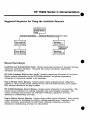
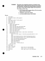
HP 75000 Series C Documentation
Suggested Sequence for Using the Available Manuals
1installation
and]
Gettixu Started
I Guide I
Instrument Applications
Using the Mainframe front panel or pacer
I
Plug-in Module
User's Manuals
Mainframe
User's Manual
Plug-in Module
Service Manuals
Mainframe
Service Manual
Manual Descriptions
Installation and Getting Started Guide. Contains step-by-step instructions for all aspects of plug-in
module and mainframe installation. This guide also contains introductory programming
information and examples.
HP El405 Command Module User's Guide. Contains programming information for the Control
Module, operation information (for the HP E1400B mainframe), and general programming
information for instruments installed in the mainframe.
Plug-In Module User's Manuals. Contains plug-in module programming and configuration
information. These manuals contain examples for the most-used module functions, and a complete
SCPI command reference for the plug-in module.
HP E1400B Mainframe Service Manual. Contains service information for the mainframe. This
manual contains information for ordering replaceable parts and exchanging assemblies. Also
contains information and procedures for performance verification, adjustment, preventive
maintenance, troubleshooting, and repair.
Plug-In Module Service Manuals. Contains plug-in module service information. These manuals
contain information for exchanging the module or ordering replaceable parts. Dependent on the
module, information and procedures for performance verification, adjustment, preventive
maintenance, troubleshooting, and repair are also provided.
0
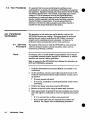
How to Use this Manual
Manual Overview
This manual shows how to service the HP E1426A 500 MHz Digitizing
Oscilloscope. Oscilloscope operation, installation, and configuration
information is not discussed in this manual. Refer to the "HP 75000
Series C HP E1426A User's Manual" for installation, configuration,
and operating information.
Manual Content
This manual has eight chapters and one appendix.
C h a p t e r 1 General Information: provides a basic description,
and lists available options and accessories. Also lists the tools
and test equipment required for service.
C h a p t e r 2 Installation: contains information and procedures
required to install the oscilloscope into the mainframe, perform
initial inspection, prepare for use, and storing and shipping
instructions.
C h a p t e r 3 Operating Instructions: contains information and
procedures required to operate the oscilloscope, perform scheduled
preventive maintenance, and perform the operator's check.
C h a p t e r 4 Verification Tests: contains information and
procedures required to test the oscilloscope. Three levels are
provided for functional verification, operation verification, and
performance verification.
C h a p t e r 5 Adjustments: contains information and procedures
required to readjust the oscilloscope to within its rated
specifications.
C h a p t e r 6 Replaceable Parts: lists the part numbers for all
user replaceable parts in the oscilloscope. Also provides
information on ordering spare parts and module/assembly
exchange.
C h a p t e r 7 Manual Changes: contains information required to
adapt this manual to instruments whose serial numbers are lower
than those listed on the title page.
C h a p t e r 8 Service: contains information and procedures to aid
in fault isolation and repair of the oscilloscope.
Appendix A References: contains a list of all reference
documentation required when servicing the oscilloscope.
Chapter 1
1-1
1-2
13
14
15
1-6
1-7
18
1-9
1-10
page
1-1
1-1
1-1
1-1
1-1
1-1
13
13
13
13
13
.....................................................................
Introduction .........................................................................................
Specifications Considerations ............................................................
Safety Considerations .........................................................................
Manual Updates ..................................................................................
Description ..........................................................................................
Instruments Covered by This Manual ...............................................
Options ................................................................................................
Accessories Supplied ...........................................................................
Equipment Available ..........................................................................
Recommended Test Equipment ..........................................................
GENERAL INFORMATION
Page
Chapter 2
INSTALLATION .........................................................................................2 1
2 1 Introduction ......................................................................................... 2 1
2 2 Initial Inspection ................................................................................ 2 1
23 Preparation for Use ............................................................................. 2 1
24 Operating Environment .................................................................... 2 2
25 Storage and Shipment .......................................................................... 2 2
2-6 Environment ....................................................................................... 2 2
2 7 Packaging .......................................................................................... 2 2
Chapter 3
page
3-1
3-1 Introduction
3-1
$2 Safety Considerations ......................................................................... 3-1
33 Preventive Maintenance .................................................................... 3-2
34 RequiredEquipment ........................................................................... 3-2
3-5 Cleaning Procedures .......................................................................... 34
3-6 Operation ............................................................................................. 34
$7 Operator's Checks ............................................................................. 34
.................................................................
.........................................................................................
OPERATING INSTRUCTIONS
Contents
.1
Chapter 4
page
VERIFICATION TESTS ............................................................................. 41
Introduction .........................................................................................
Equipment Required ...........................................................................
Test Record .........................................................................................
Calibration Cycle ................................................................................
Test Procedures ...................................................................................
Functional Verification .......................................................................
Self-Test Procedure .............................................................................
Operation Verification ........................................................................
Performance Verification ..................................................................
DC Calibrator Test Procedure .............................................................
Input Resistance Test Procedure ........................................................
Voltage Measurement Accuracy Test Procedure ...............................
Offset Accuracy Test Procedure .........................................................
Bandwidth Test Procedure ..................................................................
Time Measurement Accuracy Test Procedure ...................................
Trigger Sensitivity Test Procedure ....................................................
Oscillator Output Test Procedure ........................................................
Chapter 5
ADJUSTMENTS ....................................................................................... 51
51 Introduction ......................................................................................... 51
5 2 Equipment Required ........................................................................... 31
53 Vertical Calibration Procedure .......................................................... 5 2
54 Delay Cal Calibration Procedure ....................................................... 54
55 Time Null Calibration Procedure ...................................................... 56
56 Logic Trigger Calibration Procedure ................................................. 5-8
57 High Frequency Pulse Response Adjustment Procedure ................... 510
Chapter 6
Page
REPLACEABLE PARTS ............................................................................ 6 1
6 1 Introduction ......................................................................................... 61
6 2 Ordering Information ..................................................................... 61
K3 Exchange Assemblies ........................................................................ 61
&IAbbreviations .................................................................................... 61
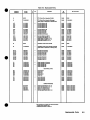
645 Replaceable Parts List ........................................................................ 61
Chapter 7
page
................................................................................ 7-1
7-1 Introduction ......................................................................................... 7-1
Chapter 8
page
SERVICE .................................................................................................... 81
81 Introduction ......................................................................................... 81
8 2 Safety Considerations .........................................................................
81
83 Equipment Required ........................................................................... 8 2
84 Troubleshooting .................................................................................. 8 2
8-5 General ............................................................................................... 8 2
86 Service Aids ....................................................................................... 83
8 7 Visual Inspection ................................................................................ 83
88 Troubleshooting Test .......................................................................... 84
8 9 Repair and Replacement .................................................................... 86
810 Disassembly and Reassembly ............................................................ 8-6
811 Repair .................................................................................................. 810
MANUAL CHANGES
Contents
.2
Appendias
References
A
....................................................................
page
A-1
LlST OF TABLES
.
No Title
.
........................................
.....................................
Verification Test Record ...................................................
Part Numbers for Exchange Assemblies .................................
Reference Designators and Abbreviations ...............................
Replaceable P a r t s
............................................................
Code List of Manufacturers ..................................................
1.1 Recommended Test Equipment
3- 1. Preventive Maintenance Equipment
4.1
.
6.1 .
6.2
6.3 .
6.4 .
.
m
1-4
3-2
4-26
6-2
6-3
6-5
6-8
LlST OF ILLUSTRATIONS
Title
p
a
s
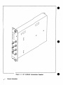
HP E1426AlE Accessories Supplied ........................................ 1-0
Oscilloscope Module Block Diagram ..................................... 1-2
DC Calibrator Test Set-up ................................................... 4 4
Input Resistance Test Set-up ......................................... 4-6
Voltage Measurement Accuracy Test Set-up ............................. 4-8
m s e t Accuracy Test Set-up ................................................ 411
Bandwidth Test Set-up ...................................................... 414
Time Measurement Accuracy Test Set-up ................................ 4-18
Trigger Sensitivity Test Set-up ............................................ 4-21
Oscillator Output Test Set-up ............................................... 4-24
Example: Vertical Calibration Setup ..................................... 5-2
Example: Delay Calibration Setup ........................................ 5-4
Example: Time Null Calibration Setup .................................. 5-6
Example: Logic Trigger Calibration Setup .............................. 5-8
High Frequency Pulse Response Adjustment Setup ..................... 5-11
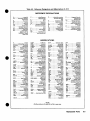
Oscilloscope Replaceable Parts ............................................
6-6
A1 CPU PCA Replaceable Parts ............................................ 6-7
A2 Acquisition PCA Replaceable Parts ................................... 6-7
Contents
.3
Figure 1-1. HP E1426AlE Accessories Supplied
1-0
General Information
General Information
1-1. Introduction
The HP E1426A Service Manual contains all the information
required to test, adjust, troubleshoot, and repair the Hewlett-Packard
Model E1426A C Size VXI 500 MHz Digitizing Oscilloscope. Figure 11 shows the HP E1426A Oscilloscope, along with all of the externally
supplied accessories. Additional copies of the HP E1426A User's
Manual and Service Manual can be ordered separately through your
nearest Hewlett-Packard ofice.
1-2. Specif ications
Considerations
Instrument specifications are listed in Appendix A of the HP
E1426A User's Manual. These specifications are the performance
standards or limits against which the instrument may be tested.
1-3. Safety
Considerations
This product is a Safety Class I instrument, that is, one provided with
a protective earth terminal when installed in the mainframe. The
mainframe, oscilloscope, and all related documentation should be
reviewed for familiarization with safety markings and instructions
before operation or service. Refer to the Safety Considerations page
found a t the beginning of this manual for a summary of the safety
information. Safety information for preventive maintenance,
testing, adjusting, or service is found in appropriate places throughout
this manual.
1-4. Manual Updates Manual
Updates provide information necessary to update the manual.
The Manual Update is identified by the manual print date and part
number, both of which appear on the manual title page.
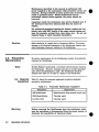
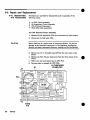
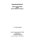
1-5. Description
The Oscilloscope module is a general purpose, four channel, 500 MHz
(repetitive bandwidth) oscilloscope, which provides all the versatility
and capability of digitizing oscilloscopes. The Oscilloscope module is
a VXIbus C-Size message-based product, and can operate in a C-Size
VXIbus mainframe using an HP El405 Command Module.
The Oscilloscope module is comprised of a CPU Printed Circuit
Assembly (PCA) (HP P/N E1426-69501) and a n Acquisition PCA (HP
P/N E1426-69502).
General Information
1-1
The Acquisition PCA attenuatedamplifies each of the four inputs.
The conditioned input signal is then routed to a track and hold
circuit. The signal is then multiplexed to an A/D Converter where i t
is changed into a digital word. This digital information is stored for
use by the CPU PCA. A replica of the conditioned input signal is also
used for triggering. Additional functions include:
Time base circuit provides the timing signals necessary for
data acquisition.
AC calibrator circuit provides signals for probe compensation,
trigger event, and calibration.
DC calibrator circuit provides a calibration signal.
The CPU PCA contains the control and interface circuits necessary to
direct oscilloscope operations. Control information (COMP or SCPI)
is received from the mainframe controller, and the necessary
instructions are sent to the Acquisition PCA to perform the specific
task. When the digital waveform information is received from the
Acquisition PCA, all the user requested parameters are measured and
routed to the mainframe. Additional functions include:
n ' L and ECL trigger signals from the mainframe are routed
to the Acquisition PCA to perform "external trigger"
functions.
'M'L and ECL trigger signals from the oscilloscope are routed
to the mainframe over the backplane trigger bus lines.
Trigger circuit provides a I T L Trigger output signal on the
front panel.
Refer to the H P E1426A User's Manual for additional information on
the HP E1426A Oscilloscope.
TOIFROM
MAINFRAME
I
I
I
I
I
I
.
-1
cALq
II
1 1
lmpuT I I
1
!
I
1
!
I
I
INTERNAL
TIIMCCLI
I
1
AC CAL
Figure 1-2.
1-2
JI
General Information
Oscilloscope Module Block Diagram
I
I
I
.-
TRIGGER
1-6. Instruments
Covered by this
Manual
Instruments covered by this manual are identified by a serial
number prefix listed on the title page. Hewlett-Packard uses a two
part serial number in the form X)(XXAYYYYY,where XMM is the
serial prefix, A is the country of origin (A=USA) and YYYYY is the
serial suffix. The serial number prefix identifies a series of
identical instruments. The serial number suffix is assigned
sequentially and is unique to each instrument. If the serial number
prefix of your instrument is greater than the one listed on the title
page, a yellow Manual Update supplement will explain how to adapt
this manual to your instrument. If the serial number prefix of your
instrument is lower than the one listed on the title page, information
contained in Chapter 7 (Manual Changes) will explain how to adapt
this manual to your instrument.
1-7. Options
There are no options currently available for the HP E1426A
Oscilloscope Module.
1-8. Accessories
Supplied
There are no accessories currently available for the HP E1426A
Oscilloscope Module.
1-9. Equipment
Available
A number of oscilloscope accessories are available for use with
the HP E1426A Oscilloscope, and include:
The HP 10400A Miniature Probe Family
The HP 10002A 50:l Voltage Divider Probe
The HP 10020A Resistive Divider Probe Kit
The HP 1124A Active Divider Probe Kit
For a complete list of oscilloscope accessories currently available,
contact your nearest Hewlett-Packard sales office.
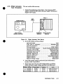
1-10. Recommended
Test Equipment
Table 1-1lists the test equipment recommended for testing, adjusting
and servicing the oscilloscope. Essential requirements for each piece
of test equipment are described in the Critical Specifications column.
Other equipment can be substituted if it meets or exceeds the critical
specifications.
General Information
1-3
Table 1-1.
Recommended Test Equipment
Crltlcal Speclf lcatlons
Instrument
Recommended
Model
Controller. HP-IB
HP-IB compalibility as defied by IEEE Standard
488-1978 and the identical ANSI Standard MCl.1:
SHl. AHl. 7'2. TEO, L2. LEO. SRO. RM. PPO. DCO.
DTO. and C1, 2, 3.4, 5.
Mainframe
Compatible with the oscilloscope
Slot 0 Command Module
VXI "C" size w/HPIB
Digital Multirneter
5 1/2 digit resolution
dc voltage accuracy 8 ppm/yr
4-wire resistance accuracy f0.25%
Fast-rise Pulse Generator
Rise Time < 175ps (faster is better)
Oscilloscope
General-purpose
Power MetaPower Sensor
1-500 MHz. -70 dBm to 0 dBm. 3% accuracy
Power Splitter
50 fl type N. outputs differ by 4 . 1 5 dB
HP 11667A
Power Supply
7 mV -35 V dc. 0.1 mV resolution
HP 6114A
Signal Generator
1-500 MHz sine wave
amplitude 3-170 mVrrns
time base accuracy f0.001%
Cables and Adapters
Adapter (2)
Adapta (3)
Adapter
Adapter
Adaprer
Adapter
Adapter
Cable (2)
Cable (4)
Cable
HP Series 200/300
PPL 1110B driver (note)
PPL 1107B head (note)
HP 54501A
HP 436A18482A
HP 8656B Opt 001
BNC to dual banana
BNC tee (mXf)(f)
BNC ( f ) ( f )
N (m) to BNC ( f )
N (m) to BNC (m)
Type N (f) to BNC (rn)
Type N (f) to SMA ( 4
BNC-3 foot
BNC-9 inch
Type N-3 foot (m) (rn)
Note PPL = Picosecond Pulse Labs
*
M = Preventative Maintenance. F = Functional Verification Check. C = Operational Verification Tests. P = Perforrnanct
Verification Tests. A = Adjustments, T = Troubleshooting
1-4
General Information
Installation
2-1.
Introduction
This chapter provides the information needed to install the HP
E1426A Oscilloscope. Included is information pertinent to initial
inspection, preparation for use, environment, storage and shipment.
2-2. Initial Inspection
Warning
To avoid hazardous electrical shock, do not perform electrical
tests when there are signs of shipping damage to any portion
of the outer enclosure (covers, panels, etch
Inspect the shipping container for damage. If the shipping container
or cushioning material is damaged, it should be kept until the
contents of the shipment have been checked for completeness and the
instrument has been checked mechanically and electrically. The
contents of the shipment should be a s shown in Figure 1-1. Procedures
for checking electrical performance are given in Chapter 4. If the
contents are incomplete, if there is mechanical damage or defect, or if
the instrument does not pass the electrical performance test, notify the
nearest Hewlett-Packard ofice. If the shipping container is damaged
or the cushioning material shows signs of stress, notify the carrier as
well a s the Hewlett-Packard ofice. Keep the shipping materials for
the carrier's inspection.
2-3. Preparation
for Use
Complete instructions for preparing the HP E1426A Oscilloscope for
use are provided in the HP E1426A User's Manual, the HP E1400B
Mainframe User's Manual, and the HP El405 Command Module
User's Manual. Procedures include:
HP E1426A User's Manual (Chapter 2)
Logical Address Switch Selection
Bus Request/Grant Level Switch Selection
Servant Area Switch Selection
Connecting User Inputs
Mainframe Installation
HP E1405A Command Module User's Manual (or applicable
command module manual)
Interface Cable Connection
Addressing the Plug-In Modules
System Configuration
Installation
2-1
HP E1400B Mainframe User's Manual (or applicable mainframe
manual)
AC Power Selection and Connection
Module Installation
2-4. Operating
Environment
The operating environment should be within the following :
limitations
........................................... 0 to +55"C
......................... 65% relative (0 to +40°C)
Temperature
Humidity
2-5. Storage and
Shipment
2-6. Environment
The instrument should be stored in a clean, dry environment. The
following environmental limitations apply to both storage and
shipment:
........................................ 4 0 to +75OC
...................... <65% relative (0 to +40°C)
Temperature
Humidity
2-7. Packaging
Preparation for Packaging. Remove any adapters or connectors
before packaging instrument for shipping.
Tagging for Service. If the instrument is being returned to HewlettPackard for service, please complete one of the blue repair tags
located a t the back of this manual and attach it to the instrument.
Original Packaging. Containers and materials identical to those
used in factory packaging are available through Hewlett-Packard
offices. Mark the container "FRAGILE to assure careful handling.
In any correspondence refer to the instrument by model number and
full serial number.
Other Packaging. The following general instructions should be used
for re-packaging with commercially available materials:
a. Wrap the instrument in heavy paper or plastic. (If shipping to
a Hewlett-Packard ofice or service center, complete one of the
blue tags mentioned above and attach it to the instrument.)
b. Use a strong shipping container. A double-wall carton made
of 2.4 MPa (350 psi) test material is adequate.
c. Use enough shock-absorbing material (75 to 100 mm layer; 3 to
4 inches) around all sides of the instrument to provide firm
cushion and prevent movement in the container. Protect the
front panel with cardboard.
d. Seal the shipping container securely.
e. Mark the shipping container
handling.
2-2
lnstallatlon
"FRAGILE to assure careful
Operating Instructions
3-1. Introduction
This chapter provides operating information for the HP E1426A
Oscilloscope. Included are detailed operator's preventive
maintenance procedures, operating instructions, and operator's
checks. Both preventive maintenance and the operator's checks
should be performed on a regular scheduled basis to keep the
oscilloscope in a n operational condition, and also prevent more
serious malfunctions from occurring.
3-2. Safet
Considera ions
This paragraph contains information, cautions, and warnings which
must be followed for your protection and to avoid damage to the
equipment when performing preventive maintenance.
Y
Before applying power, verify that the mainframe (the oscilloscope is
installed in) is set to match the available line voltage and the correct
fuse is installed. An uninterruptible safety earth ground must be
provided from the main power source to the product input wiring
terminals, power cord, or supplied power cord set.
Warning
Any interruption of the protective (grounding) conductor
(inside or outside the instrument) o r disconnecting the
protective earth terminal will cause a potential shock hazard
that could result in personal injury. (Grounding one
conductor of a two conductor outlet is not sufficient
protection.) In addition, verify that a common ground exists
between the unit under test and this instrument prior to
energizing either unit.
Whenever it is likely that the protection has been impaired,
the instrument must be made inoperative and be secured
against any unintended operation.
If this instrument is to be energized via an autotransformer
(for voltage reduction) make sure the common terminal is
connected to neutral (that is, the grounded side of the mains
supply).
Servicing instructions are for use by service-trained
personnel only. To avoid dangerous electric shock, do not
perform any servicing unless qualified to do so.
Operatlng lnstructlons
3-1
Maintenance described in the manual is performed with
power supplied to the instrument while protective covers are
removed. Energy available at many points may, if contacted,
result in personal injury. Where maintenance can be
performed without power applied, the power should be
removed.
Capacitors inside the instrument may still be charged even if
the instrument has been disconnected from its source of
supply
For continued protection against fire hazard, replace the line
fuse(s) only with 250V fuse(s1 of the same current rating and
type (for example, normal blow, time delay, etc.). Do not use
repaired fuses or short circuited fuseholders.
Caution
3-3. Preventive
Maintenance
Note
3-4. Required
Equipment
Static electricity i s a major cause of component failure. To prevent
damage to the electrical components in the Oscilloscope, observe antistatic techniques whenever working on the Oscilloscope.
Preventive maintenance for the Oscilloscope consists of periodically
cleaning the Oscilloscope.
Hewlett-Packard recommends a 12-month interval between cleaning
the Oscilloscope. However, cleaning intervals are mostly dependent
upon where the Oscilloscope is used. The Oscilloscope should be
cleaned more often if i t is used in a dusty or very humid area.
Table 3-1 shows the necessary equipment to perform scheduled
preventive maintenance.
Table 3-1.
Description
ISoft-bristle
brush
Warning
3-2
Operating instructions
Preventive Maintenance Equipment
I
Requirement
Removing dust from printed circuit card
Mild Soap Solution
Cleaning panel
Lint-free cloth
Cleaning panel
Before removing the Oscilloscope from the mainframe, make
sure the mainframe is disconnected from the power source, to
eliminate the possibility of electrical shock.
I
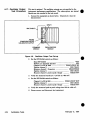
3-5. Cleaning
Procedures
Caution
The following items should be cleaned a t 12-month intervals and
more oRen if located in very dusty or humid areas:
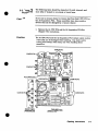
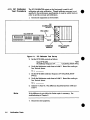
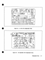
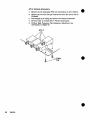
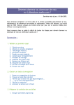
Do not use a vacuum cleaner to remove dust from the A1 CPU PCA or
the A2 Acquisition PCA These assemblies have static sensitive
devices that can be damaged by a vacuum cleaner.
1. Remove the A1 CPU PCA and the A2 Acquisition PCA See
Chapter 8 for instructions.
Caution
The A1 CPU PCA and the A2 Acquisition PCA contain static sensitive
devices that can be damaged when handling. Use static control
devices (wrist straps, static mats, etc) when handling these
assemblies.
CONTACTS
CONTAC
'ACTS
FRONT VIEW
(ASSEMBLED)
TOP VIEW
(SHIELD REMOVED)
Operating Instructions
3-3
2. Using a soft-bristle brush only, remove dust from the printed
circuit surface.
3. Clean the backplane connector contacts, the front panel BNC
connectors, and any other contacts on both assemblies. Clean all
interconnecting cable contacts.
4. Reassemble the A1 CPU PCA and the A2 Acquisition PCA See
Chapter 8 for instructions.
5. Clean the Oscilloscope panel and shield.
Operation
Complete instructions for operation of the Oscilloscope are provided in
the HP E1426A User's Manual. Information includes:
Getting Started
Configuring the Oscilloscope
Using the Oscilloscope with COMPatible or SCPI
Oscilloscope Command References in COMPatible and SCPI
Error Messages in COMPatible and SCPI
3-7. Operator's
Checks
Note
The operator's checks should be performed after preventive
maintenance (minimum), or any time to verify that the Oscilloscope
is connected properly and is responding to the simplest commands.
If necessary, refer to the HP E1405A Command Module User's
Manual (or applicable command module manual) for information on
address selection and external cabling guidelines.
Refer as required to the HP E1426A User's Manual for information
on SCPI and COMPatible commands.
1. Verify the Oscilloscope and Command Module are installed in the
mainframe.
2. On the mainframe, connect a power cable and set the power to ON.
Verify the mainframeJcommand module performs a proper powerup sequence.
If correct, proceed with step 3.
If incorrect, troubleshoot mainframe/command module before
proceeding.
3. Perform clear status, reset, then preset the Oscilloscope.
3-4
Operating Instructions
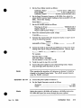
4. Execute the Oscilloscope functional test using the TEST: TALL
command.
5. Allow approximately 15 seconds for the test to complete, then read
the test event register to verify that no errors were generated
during the test.
If +O is returned, then no failure was encountered.
If any number other than 0 is returned, then a failure was
detected. See Chapter 8 for troubleshooting information.
Note
Example
Test failures can be caused by improper cabling, or improper
selection of the interface select code, primary address setting, andlor
secondary address setting. Verify proper connection and address
selection using the applicable command module and mainframe
manuals before troubleshooting.
F Othe
~ example, use:
an HP-IB select code of 7, primary address of 09, and
secondary address of 05 for the Oscilloscope
COMPatible programming language
an HP Series 2001300 Computer with HP BASIC
OUTPUT 70905; "SUMM:PRES9'
OUTPUT 70905; "TEST: TALL"
OUTPUT 70905;"SUMM:QUES:TEST?"
ENTER 70905;A
PRINT A
OUTPUT 70905; "RUN"
END
Note
Nov 15, 1990
Clear status.
Resets the Oscilloscope to its default
state.
Presets the Oscilloscope.
Perform all test routines.
Read test event register.
Enter test event register results.
Print test event register results.
Restart the instrument.
Terminate program.
After a self-test is performed, the RUN command must be executed to
restart the instrument.
Operating Instructions
3-5
Verification Tests
4-1. Introduction
Three levels of test procedures are provided in this chapter, and are used
to verify that the HP E1426A Oscilloscope is:
fully functional (Functional Verification),
meeting critical specifications after a repair (Operation
Verification), or
meeting all published specifications (Performance
Verification).
Note
To consider the tests valid, the following conditions must be met:
The HP E1426A must have a 30 minute warm-up.
The line voltage must be 115/230 Vac *lo%.
For greatest accuracy, the temperature of the test area should
be between 18°C and 28°C and should be stable to within f 1°C.
4-2. Equipment
Required
Equipment required for the verification tests is listed in Table 1-1,
Recommended Test Equipment. Any equipment that satisfies the
critical specifications given in the table may be substituted.
4-3. Test Record
Results of the verification tests may be tabulated in Table 4-1,
Verification Test Record. The Verification Test Record lists all of the
verification test specifications and the acceptable limits for each
specification. If verification test results are recorded during an
incoming inspection of the instrument, they can be used for comparison
during periodic maintenance or troubleshooting. The test results may
also prove useful in verifying operation after repairs are made.
4-4. Calibration Cycle
This instrument requires periodic verification of performance to
ensure that it is operating within specified tolerances. The performance
verification tests described in this section should be performed a t least
once every six months or 1,000 hours; under conditions of heavy usage
or severe operating environments, the tests should be more frequent.
Annual cleaning procedures are detailed in Chapter 3, Preventive
Maintenance.
Verification Tests
4-1
4-5. Test Procedures
4-6. Functional
Verification
4-7. Self-Test
Procedure
Note
I t is assumed that the person performing the verification tests
understands how to operate the mainframe, HP E l 4 2 6 4 and specified
test equipment. Equipment settings, other than those for the HP E1426A,
are stated in general terms. For example, a test might require that a
voltage of +5 Vdc be measured, however the Digital Multimeter
instructions a s to mode and range would not be specified and the
operator would be expected to set that control and other controls as
required to obtain a measurement. It is also assumed that the
technician will select the cables, adapters, and probes required to
complete the test setups illustrated in this section.
The procedures in this section are used to quickly verify that the
HP E1426A functions are working. These tests should be performed
anytime the user wants to verify that the HP E1426A is connected
properly and is responding to basic commands. All tests can be
performed without accessing the interior of the instrument.
The purpose of this test is to verify the HP E1426A is communicating
with the command module, external controller, andfor external
terminal by performing a self-test.
If necessary, refer to the HP El405 Command Module User's Manual
(or applicable command module manual) for information on address
selection and external cabling guidelines.
Refer as required to the HP E1426A User's Manual for information on
SCPI and COMPatible commands.
1. Verify the HP E1426A and Command Module are installed in the
2.
3.
4.
5.
4-2
Verlflcatlon Tests
mainframe.
On the mainframe, connect a power cable and set the power to ON.
Verify the mainframdcommand module performs a proper powerup sequence.
If correct, proceed with step 3.
If incorrect, troubleshoot mainframe/command module before
proceeding.
Perform clear status, reset, then preset the HP E1426A
Execute the test all routine using the TEST:TALL command.
Allow approximately 15 seconds for the test to complete, then read the
test event register to verify that no errors were generated during the
test.
If +O is returned, then no failure was encountered.
If any number other than 0 is returned, then a failure was
detected. See Chapter 8 for troubleshooting information.
Note
Example
Test failures can be caused by improper cabling, or improper selection
of the interface select code, primary address setting, andlor secondary
address setting. Verify proper connection and address selection using
the applicable command module and mainframe manuals before
troubleshooting.
For the example, use:
an HP-IB select code of 7, primary address of 09, and secondary
address of 05 for the HP E l426A
COMPatible programming language
an HP Series 2W300 Computer with HP BASIC
OUTPUT 70905; "*CLS8'
OUTPUT 70905; *'*RST"
OUTPUT 70905; "SUMM:PRES1*
OUTPUT 70905; "TEST: TALL"
OUTPUT 70905;"SUMM:QUES:TEST?"
ENTER 70905;A
PRINT A
OUTPUT 70905; "RUN"
END
Note
Ckar status.
Resets the HP E1426A to its default
state.
P ~ s e t the
s HP E1426A.
Perfbrm test d l routine
Read t a t event register.
Enter test ewnt register results.
Print t a t ewnt register results.
h t a t t the instrument.
Terminate program.
After a test all is performed, the RUN command must be executed to
restart the instrument.
4-8. Operation
Verification
There are no operation verification procedures for the HP E1426A
Use the Performance verification test procedures for post repair checkout.
4-9. Performance
Verification
The procedures in this section are used to test the HP E1426A
Oscilloscope modules electrical performance using the specifications
in Appendix A of the HP E1426A User's Manual as the performance
standards. These tests are suitable for incoming inspection,
troubleshooting, and preventive maintenance. All tests can be
performed without accessing the interior of the instrument.
Verlflcatlon Tests
4-3
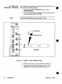
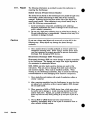
4-10. DC Calibrator
Test Procedure
The DC CALIBRATOR output on the front panel is used for selfcalibration and probe calibration. Though calibrator accuracy is not
specified in the performance specifications, i t must be within limits in
order to provide accurate self-calibration.
1. Connect the equipment a s shown below.
CALIBRAT~ON
OUTPUT
BNC CABLE
MULTIMETER
..
J
0 0
b'!
0
b$0
I
0:
COMMAND
MODULE
Figure 4-1.
MODULE
DC Callbrator Test Set-up
2. Set the HP E1426A controls a s follows:
. ...
.
.
.
Reset HP El426A .... . .......... ...... .......... .... *RST
DC Calibrator Output to 0 V ...... . CAL:SCAL:DOUT ZVOL
.
Verify the Multimeter reads close to 0.000 V. Record the reading to
four decimal places.
v1 =
Set the HP E1426A Calibrator Output to 5 V (CAL:SCAL:DOUT
FVOL).
Verify the Multimeter reads close to 5.000 V. Record the reading to
four decimal places.
v2 =
Subtract V1 from V2. The difference should be between 4.990 and
5.010 V.
Note
If the difference is not within the limits repair is necessary. See
troubleshooting in Chapter 8.
-
-
-
7. Disconnect test equipment.
4-4
Verlflcatlon Tests
Example
This program will automatically perform a DC Calibrator test. The
program will pause to allow the user to get the reading from the
multimeter.
The example is written using:
an HP-IB select code of 7, primary address of 09, and secondary
address of 05 for the HP E1426A
COMPatible programming language
an HP Series 200'300 Computer with HP BASIC
Execute:
10
OUTPUT 70905; e'*CLS"
20
OUTPUT 709OS;"* RST"
30
OUTPUT 70905;"CAL:SCAL: DOUT ZVOL"
40
PAUSE
50
OUTPUT 70905;"CAL:SCAL:DOUT FVOLv'
60
PAUSE
70
END
Verlflcatlon Tests
4-5
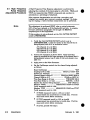
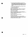
4-1 1. Input Resistance
jest Procedure
This test checks the input resistance of the vertical inputs. A fourwire measurement is used for accuracy at 50 R.
1. Connect the equipment as shown below. Use the BNC-to-banana
adapters to connect one of each BNC cable to the four-wire resistance
connections on the multimeter, and connect the free ends of the
cables to a BNC tee. Connect the male end of the BNC tee to the HP
E1426A channel 1input.
BNC TO DUAL
MULTIMETER
LO BNC CABLE COMMAND
MODULE
Flgure 4-2.
OSCILLOSCOPE
MODULE
Input Resistance Test Set-up
2. Set the HP E1426A controls as follows:
Reset HP E1426A ............................................... *RST
Channel 1DC a t 1Mn .......................... CHAN1:COUP DC
3. Verify the Multimeter reads 1MR flOkR.
4. Set the HP E1426A channel 1controls to 50R (CHAN1:COUP DCF).
5. Verify the Multimeter reads 5W *0.5R.
6. Repeat steps 1through 5 for channels 2,3, and 4.
Notes
When repeating the procedure, all references to channel 1 should be
changed to the channel being tested.
Failure of this test indicates a faulty attenuator if resistance is out of
specifications. One of the PCA's also may be a t fault if input resistance
cannot be changed. See troubleshooting in Chapter 8.
7. Disconnect test equipment.
4-6
Verification Tests
Example
This program will automatically prompt the user through the steps
required to perform an input resistance test. The program will pause
to allow the user to get the reading from the multimeter.
The example is written using:
a n HP-IB select code of 7, primary address of 09, and
secondary address of 05 for the HP E1426A
COMPatible programming language
an HP Series 2001300 Computer with HP BASIC
Execute:
OUTPUT 7 0 9 0 5 ; "*CLS"
OUTPUT 70905;"*RSTn
FOR C h a n n e l = l TO 4
PRINT " C o n n e c t t h e m u l t i r n e t e r t o s c o p e c h a n n e l " S V A L S ( C h a n n e 1 )
PRINT "1 MOhrn"
OUTPUT 70905;"CHAN"CVALS ( C h a n n e l ) 6 " :COUP DC"
PAUSE
PRINT "50 Ohm"
OUTPUT 70905;"CHANW6VALS ( C h a n n e l ) 6": COUP DCF"
PAUSE
NEXT C h a n n e l
OUTPUT 70905;"*RST"
130
END
Nov 15. 1990
Verification Tests
4-7
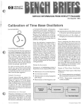
4-1 2. Voltage
Measurement Accuracy
Test Procedure
This test verifies the voltage measurement accuracy of the
instrument. A dual cursor measurement is made so offset errors are
not a factor.
1. Connect the equipment as shown below.
Use a banana-to-BNC
adapter to connect the BNC cable to the power supply. Monitor the
supply with the Multimeter. Set the power supply for 0 V output.
POWER SUPPLY
BNC TO DUAL
BNC TO DUAL BANANA
ADAPTER
Flgure 4-3.
C O M ~ N D OSC~LLOSCOPE
MODULE
MODULE
1
Voltage Measurement Accuracy Test Set-up
2. Set the HP E1426A controls as follows:
Reset HP E1426A ............................................... *RST
Time base to automatic ............................ T1M:MOD AUT
Start data acquisition .......................................... RUN
Turn on channel 1 ...................................VIEW CHANl
Turn off unused channels ..... BLAN CHANB,CHAN3,CHANI
Channel 1to DC at 1MR ........................ CHAN1:COUP DC
Acquisition type to average ..................... ACQ:TYP AVER
Acquisition count to 32 ............................. ACQ:COUN 32
Channel 1range to 40 V ........................ CHAN 1:RANG 40
Channel 1 offset to 17.5 V ...................... CHAN1:OFFS 17.5
Measure channel 1 ......................... MEAS:SOUR CHANl
Digitize channel 1 ............ ....................... DIG CHANl
Measure average voltage ............................ MEAS:VAV?
:.
3. Verify that average voltage as measured by the HP E1426A is close to
0 volts. Record the reading.
v1 =
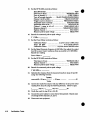
4. Set the power supply to output 35 Vdc. Repeat steps 2 and 3. Record the
reading.
5. Subtract V l from V2. The difference should be between 34.5 V and
35.5 v.
4-8
Veriflcatlon Tests
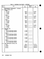
6. Repeat steps 2 throwh 5 for all the HP E1426A RANGe and OFFSet
values, and power sipply voltages specified in the table below.
Tolerance
Power Supply
Limits
OFFSet
17.50000 V
M.5 V
34.5 V to 35.5 V
35.00 V
7.00000 V
14.00 V
M.2 V
13.8 V to 14.2 V
3.50000 V
7.000 V
M.1 v
6.9 v to 7.1 V
1.75000 V
3.500 V
M.05 V
3.45 v to 4.05 v
700.000 mV
1. a 0 v
M.02 v
1.38 V to 1.42 V
350.000 mV
700.0 mV
f10 mV
690 mV to 710 mV
175.000 mV
350.0 mV
f5 mV
345 mV b 355 mV
70.000 mV
140.0 mV
S
2 mV
138 m V b 142 mV
35.000 mV
70.0 mV
f l mV
69 mV to 71 mv
17.500 mV
35.0 mV
M.7 mV
34.3 mV to 35.7 mV
14.0 mV
7.000 mV
M.7 mV
13.3to 14.7 mV
8 mV 3.500 mV I
7.0 mV
6.3 mV to 7.7 mV
IL
'For 40 mV to 8 mV ranaes. it is necessarv to disconnect thle multimeter after
rerifying the output of t<e supply to avoid kupling noise into the channel.
1
I
7. Repeat steps 2 through 6 for channels 2,3, and 4.
Notes
When repeating the procedure, all references to channel 1should be
changed to the channel being tested. Turn off all unused channels
using the BLANk command.
Voltage measurement errors can be caused by the need for self
calibration. Perform vertical calibration, (see Adjustment procedures,
Chapter 5) before troubleshooting instrument. If self-calibration fails to
correct problem, the cause may be the attenuator or A2 PCA See
troubleshooting in Chapter 8.
8. Disconnect test equipment.
Veriflcatlon Tests
4-9
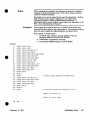
Example
This program will automatically prompt the user through the steps
required to perform a voltage accuracy test, and print out the results of
each measurement. The data at the end of the program corresponds to
the values for range, offset and supply voltage in each measurement.
The example is written using:
an HP-IB select code of 7, primary address of 09, and
secondary address of 05 for the HP E1426A
COMPatible programming language
an HP Series 20W300 Computer with HP BASIC
Execute:
OPTION BASE 1
DIM Range(l2) ,Offset (12),Power-supply (12),Zero-offset (12)
RESTORE
READ Range(*) ,Off set ( * ) ,Power-supply ( * )
OUTPUT 70905; "*CLSe*
OUTPUT 70905; "*RSTe8
FOR Channel=l TO 4
OUTPUT 70905;"TIM:MOD AUT"
OUTPUT 70905;"RUNW
OUTPUT 70905;"BLAN CHANl,CHAN2,CHAN3,CHAN4"
OUTPUT 70905;"VIEW CHANW&VAL$(Channel)
OUTPUT 70905;"CHAN"&VAL$(Channel)&n:COUP DC"
OUTPUT 70905;"ACQ:TYP AVER"
OUTPUT 70905;"ACQ:COUN 32"
PRINT "Connect the power supply to scope channel @*&VAL$(Channel)
FOR Measurement-1 TO 12
PRINT "Set the power supply to 0 voltse1
PAUSE
"&VALS(Range(Measurement))
OUTPUT 70905;"CHAN"&VAL$(Channel)6":RANG
OUTPUT 70905;*THAN"&VALS (Channel)6":OFFS "&VAL$ (Offset (Measurement))
OUTPUT 70905;wMEAS:SOUR CHANn&VAL$(Channell
OUTPUT 70905;"DIG CHAN9'&VAL$(Channel)
OUTPUT 70905; "MEAS: VAV?"
ENTER 70905;Zero-val
PRINT "Set the power supply to n6VAL$(Power-supply(Measurement))6" volts"
PAUSE
OUTPUT 70905; "DIG CHAN"&VAL$ (Channel)
OUTPUT 70905;"MEAS:VAV?"
ENTER 70905;Voltage-val
Result-Voltage-val-Zero-val
PRINT "Result = "&VAL$ (Result)
NEXT Measurement
NEXT Channel
OUTPUT 70905; "*RST9'
!Range values for each measurement
DATA 4O,l6,8,4,l. 6,800E-3,400E-3,160E-3,80E-3,40E-3,16E-3, 8E-3
!Offset values for each measurement
DATA 17.5,7,3.5,l.75,7OOE-3,3SOE-3,l75E-3,7OE-3,3SE-3,
l7.5E-3,7E-3,3.SE-3
!Power supply values for each measurement
DATA 35,14,7,3.5,1.4,700E-3,350E-3,140E-3,70E-3,35E-3,14E-3,7E-3
END
Verlflcation Tests
February 9, 1991
4-13. Offset Accuracy
Test Procedure
This test verifies offset accuracy.
1. Connect the equipment as shown below. Use a banana-to-BNC
adapter to connect the BNC cable to the power supply. Set the power
Supply for 20 V output.
INPUT 1
BNC
CABLE
POWER SUPPLY
,ElEl
BNC TO DUAL
BANANA ADAPTER
COMMAND
MODULE
-
Flgure 4-4.
OSCILLOSCOPE
MODULE
-
--
Offset Accuracy Test Set-up
2. Set the HP E1426A controls as follows:
Reset HP E1426A ............................................... *RST
Time base to automatic ............................ T1M:MOD AUT
Start data acquisition .......................................... RUN
Turn on channel 1 ................................... VIEW CHANl
Turn off unused channels ..... BLAN CHAN2,CHAN3,CHAN4
Channel 1to DC at 1MR ........................ CHAN1:COUP DC
Acquisition type to average ..................... ACQ:TYP AVER
Acquisition count to 32 ............................. ACQ:COUN 32
Channel 1range to 4 V ........................... CHAN1:RANG 4
Channel 1offset to 20 V ........................... CHAN1:OFFS 20
Measure channel 1 ......................... MEAS:SOUR CHANl
Digitize channel 1 ..................................... DIG CHANl
Measure average voltage ............................ MEASVAV?
3. Verify that average voltage a s measured by the HP E1426A is
between 19.820 V and 20.180 V.
4. Repeat steps 2 and 3 for all the HP E1426A RANGe and OFFSet
values, and power supply voltages specified in the table below.
RANG9 OFFSet
4V
20.0000 V
Power Supply
20.000 V
[
I
Tolerance
f180 mV
I
1
Limits
19.82OVto20.180V
Verlflcatlon Tests
4-11
5. Repeat steps 2 through 4 for channels 2,3,and 4.
Notes
When repeating the procedure, all references to channel 1should be
changed to the channel being tested. Turn off all unused channels
using the BLANk command.
Offset errors can be caused by the need for self calibration. Perform
vertical calibration, (see A4justment procedures, Chapter 5) before
troubleshooting instrument. If self-calibration fails to correct problem,
cause may be the attenuator or A2 PCA See troubleshooting in Chapter
8.
6.
4-12
Verification Tests
Disconnect test equipment.
Example
This program will automatically prompt the user through the steps
required to perform an offset accuracy test, and print out the results of
each measurement. The data a t the end of the program corresponds to
the values for range, offset and supply voltage in each measurement.
The example is written using:
an HP-IB select code of 7, primary address of 09, and secondary
address of 05 for the HP E1426A
COMPatible programming language
an HP Series 2W300 Computer with HP BASIC
Execute:
OPTION BASE 1
DIM Range (31,Off set (3),Power-supply (3)
RESTORE
READ Range(*),Offset(*),Power~supply(*)
OUTPUT 70905;"*CLS"
OUTPUT 70905; "*RST"
FOR Channel=l TO 4
OUTPUT 70905;"TIM:MOD AUT"
OUTPUT 70905;"RUNN
OUTPUT 70905;"BLAN CHANl,CHAN2,CHAN3,CHAN4"
OUTPUT 70905; "VIEW CHANelCVALS(Channel)
OUTPUT 70905; e'CHAN"&VAL$ (Channel)6" :COUP DC"
OUTPUT 70905;"ACQ:TYP AVER"
OUTPUT 70905; "ACQ:COUN 32"
PRINT "Connect the power supply to scope channel "hVALS(Channe1)
FOR Measurement=l TO 3
PRINT "Set the power supply to "&VAL$ (Power-supply (Measurement)) & " volts"
PAUSE
OUTPUT 70905;~THANv'&VAL$(Channel)6":RANG "&VAL$ (Range(Measurement))
OUTPUT 70905;"CHAN"&VAL$ (Channel)6":OFFS "&VAL$ (Offset (Measurement))
OUTPUT 70905;"MEAS:SOUR CHANg1&VALS(Channel)
OUTPUT 70905; "DIG CHAN"&VAL$ (Channel)
OUTPUT 70905; "MEAS:VAV?"
ENTER 70905;Voltage-val
PRINT "Result = "&VAL$ (Voltage-val)
NEXT Measurement
NEXT Channel
OUTPUT 70905;"*RSTm
DATA 4,l. 6,800E-3
!Range values for each measurement
300
DATA 20,9,5
!Offset values for each measurement
310
DATA 20,9,5
!Power supply values for each measurement
320
END
Verification Tests
4-13
4-1 4. Bandwidth
Test Procedure
This test checks the repetitive and real time bandwidths of the HP
~i426A
1. Connect the equipment as shown below. Use a type N cable to
connect the signal generator to the power splitter input. Connect
the power sensor to one output of the power splitter. Use an N-toBNC adapter to connect the other power splitter output to the HP
E1426A channel 1input.
INPUT 1
I0
POWER METER
1
1
SIGNAL GENERATOR
/
COMMAND
MODULE
\
OSCILLOSCOPE
MODULE
DIRECT CONNECTION USING POWER
TYPE N TO BNC ADAPTER
SPLllTER
Figure 4-5.
Bandwldth 180 mV
POWER
SENSER
Bandwidth Test Set-up
2. Set the Signal Generator controls as follows:
Frequency ..................................................................... 1 MHz
Output .......................................................................-2.4 dBm
Note
Setting the output to -2.4 dBm will produce a -8.4 dBm level a t the HP
1426A 5052 input (loss occurs through the power splitter).
3. Set the HP E1426A controls a s follows:
Reset HP E1426A ............................................................. *RST
Time base to 2psec ........................................ T1M:RANG 2E-6
Turn on channel 1 ..............................................VIEW CHAN1
Turn off unused channels .... BLAN CHAN2,CHAN3,CHAN4
Channel 1to DC a t 5052 ............................. CHAN1:COUP DCF
Trigger source to channel 1 .................... TR1G:SOUR CHANl
Acquisition type to average ........................... ACQ:TYP AVER
Acquisition count to 32 ...................................... ACQ:COUN 32
Channel 1range to 40 mV .................... CHAN1:RANG 3.2E-1
Measure channel 1 ................................. MEAS:SOUR CHANl
Digitize channel 1 ................................................ DIG CHANl
Measure peak-to-peak voltage .............................. MEAS:VPP?
4. Record the measured peak-to-peak voltage.
4-14
Verification Tests
Nov 15. 1990
Set the Power Meter controls a s follows:
Calibration Factor ..................... to power sensor 1 MHz value
Press dB REF ...................................... to set a 0 dB reference
Calibration Factor .................. to power sensor 500 MHz value
Set the Signal Generator frequency to 500 MHz, then adjust the
output level for a power meter reading a s close as possible to 0.0 dB
(REL). Record the reading.
Power Meter =
Set the HP E1426A controls as follows:
Time base to 5 nsec .................................... T1M:RANG 5E-9
Digitize channel 1 ................................................DIGCHANl
Measure peak-to-peak voltage .............................. MEASVPP?
Record the measured peak-to-peak voltage.
V 500 MHz =
Calculate the response from the measured results in steps 4 and 8
using the following formula:
VSOOMHZ
response(dB) = 20 log10
-
= 20 b l 0
dB
V1 MHz
Correct the result in step 9 with any difference in the power meter
reading from step 6 using the following formula. Observe signs.
(
step 9 ) - (
step 6 ) =
dB
For example:
Result from step 9 = -2.3 dB
Power meter reading = -0.2 dB(REL)
then true response (-2.3)-(-0.2) = -2.1 dB
-
Verify the result in step 10 is 13.0 dB.
Connect the power splitter to next channel being tested. Repeat
steps 2 through 12 for channels 2,3, and 4.
Note
Bandwidth ~ 8 0mV
When repeating the procedure, all references to channel 1 should be
changed to the channel being tested. Turn off all unused channels
using the BLANk command.
13. Connect the power splitter to channel 1.
14. Set the Signal Generator controls as follows:
Frequency .................................................................... 1 MHz
Output .....................................................................-20.6 dBm
Note
Nov 15, 1990
Setting the output to -20.6 dBm will produce a -26.6 dBm level a t the
HP 1426A 5052 input (loss occurs through the power splitter).
Verification Tests
4-15
15. Set the HP E1426A controls as follows:
Reset HP E1426A ............................................... *RST
Time base to 2psec ............................... T I M W G 2E-6
Turn on channel 1 ...................................VIEW CHANl
Turn off unused channels
BLAN CHAN2,CHAN3,CHAN4
Channel 1to DC at 50Q ....................... CHAN1:COUP DCF
Trigger source to channel 1 ................ TR1G:SOUR CHANl
Acquisition type to average ..................... ACQ:TYP AVER
Acquisition count to 32 ............................. ACQ:COUN 32
Channel 1 range to 40 mV ................... CHAN1:RANG 4E-2
Measure channel 1 ......................... MEAS:SOUR CHANl
Digitize channel 1 ..................................... DIG CHANl
Measure peak-to-peak voltage ....................... MEAS:VPP?
.....
16. Record the measured peak-to-peak voltage.
V 1 MHz =
17. Set the Power Meter controls as follows:
Calibration Factor
Press dB REF
Calibration Factor
.................. to power sensor 1MHz value
................................ to set a 0 dB reference
............... to power sensor 500 MHz value
18. Set the Signal Generator frequency to 500 MHz,then a 4 u s t the output
level for a power meter reading a s close as possible to 0.0 dB (REL).
Record the reading.
Power Meter =
19. Set the HP E1426A controls as follows:
Time base to 5 nsec.. ............................. T1M:RANG 5E-9
Digitize channel 1 ..................................... DIG CHANl
Measure peak-to-peak voltage ....................... MEAS:VPP?
20. Record the measured peak-to-peak voltage.
V 500 MHz =
21. Calculate the response from the measured results in steps 16 and 20
using the following formula:
-
VSOOMHZ
response(dB) 20 loglo
-
2obgl0
I
dB
V1 MHz
22. Correct the result from step 21 with any difference in the power meter
reading from step 18 using the following formula. Observe signs.
(
step21)-(
step18)-
dB
23. Verify the result in step 22 is H . 5 dB.
24. Connect the power splitter to next channel being tested. Repeat steps
14 through 24 for channels 2,3, and 4.
25. Disconnect test equipment.
4-16
Verification Tests
Notes
Example
When repeating the procedure, all references to channel 1 should be
changed to the channel being tested. Turn off all unused channels
using the BLANk command.
Bandwidth errors can be caused by the need for adjustment. Perform
high frequency pulse response a&ustment, (see Adjustment
procedures, Chapter 5) before troubleshooting instrument. If
adjustment fails to correct problem, cause may be the attenuator or A2
PCA See troubleshooting in Chapter 8.
This program is provided to show how to perform a bandwidth test,
and print out the results of each measurement. The program pauses to
allow the user to a&ust the signal generator and power meter.
The example is written using:
an HP-IB select code of 7, primary address of 09, and
secondary address of 05 for the HP E1426A
COMPatible programming language
an HP Series 200/300 Computer with HP BASIC
ecut
OUTPUT 70905; "*CLSm
OUTPUT 70905; "'RST"
OUTPUT 70905;"TIM:RANG 2E-6"
OUTPUT 70905; "VIEW CHAN1"
OUTPUT 70905;"BLAN CHAN2, CHAN3, CHAN4"
OUTPUT 70905;"CHANl:COUP DCF"
OUTPUT 70905; *'TRIG:SOUR CHANl"
OUTPUT 70905;"ACQ:TYP AVER"
OUTPUT 70905; "ACQ:COUN 32"
OUTPUT 70905;"CHANl:RANG 3.2E-1"
OUTPUT 70905;"MEAS:SOUR CHAN1"
OUTPUT 70905; "DIG CHAN1"
OUTPUT 70905; "MEAS:VPP?'*
ENTER 70905;A
PRINT A
! To adjust signal generator and power meter.
PAUSE
OUTPUT 70905;"TIM:RANG
5E-9"
OUTPUT 70905;"MEAS:SOUR
CHAN1"
OUTPUT 70905;"DIG CHAN1"
OUTPUT 70905;"MEAS:VPP?"
ENTER 70905;B
PRINT B
PAUSE
!
To calculate response and change test set up.
! Repeat
!
Repeat
for channels 2-4
.
for <80 m V range.
END
February 9, 1991
Verification Tests
4-17
4-1 5. Time
Measurement Accuracy
Test procedure
This test uses a precise frequency source to check the accuracy of time
measurement functions.
1. Connect the equipment a s shown below. Use an N-to-BNC adapter
and BNC cable to connect the signal generator output to the HP
E1426A channel 1input.
INPUT 1
1
..
D
0
0
SIGNAL GENERATOR
11
TYPE N TO BNC
ADAPTER
Figure 4-6.
COMMAND
MODULE
OSCILLOSCOPE
MODULE
Tlme Measurement Accuracy Test Set-up
2. Set the Signal Generator controls as follows:
Frequency
................................................... 500 MHz
Output ................................................... 150 mVrms
3. Set the HP E1426A controls as follows:
Reset HP E1426A ............................................... *RST
Time base to 5 nsec .............................. T1M:RANG 5E-9
Time base delay to 0 sec ................................ T1M:DEL 0
Turn on channel 1 ................................... VIEW CHANl
Turn off unused channels ..... BLAN CHAN2,CHAN3,CHAN4
Channel 1to DC a t 50R ....................... CHAN1:COUP DCF
Acquisition type to average ..................... A C Q m AVER
Acquisition count to 8 ................................. ACQ:COUN 8
Channel 1range to 400 mV ..................... CHAN1:RANG .4
Measure channel 1 ......................... MEAS:SOUR CHANl
Digitize channel 1 ..................................... DIG CHANl
Measure time of 1st positive edge at 0 V .... MEAS:TVOL? 0,+1?
4. Record the measured time that 1st positive edge occurred a t 0 V.
4-1 8
Verlflcatlon Tests
5. Set the H P E1426A controls a s follows:
Time base delay to 8 nsec ................................. T1M:DEL 8E-9
Measure channel 1 ................................. MEASSOUR CHANl
Digitize channel 1 ................................................ DIG CHANl
Measure time of 1st positive edge at 0 V .. MEAS:TVOL? 0,+1?
6. Record the measured time t h a t 1st positive edge occurred a t 0 V.
T2 =
7. Subtract T 1 from T2. The difference should be between 7.890 nsec
and 8.110 nsec.
8. Repeat steps 2 through 7 for all t h e H P E1426A DELay values
specified in the table below.
Step 5 TIM:DEL Value
8 ns (8E-9)
128 ns (128E-9)
400 ns (4E-7)
800 ns (8E-7)
Tolerance
f110ps
f116ps
f130 ps
+I 50 ps
Limits
7.890 to 8.1 10 ns
127.884 to 128.116 ns
399.870 to 400.130 ns
799.850 to 800.150 ns
9. S e t the Signal Generator controls as follows:
Frequency .....................................................................1 MHz
Output ................................................................... 150 mVrms
10. Set the HP E1426A controls as follows:
Perform a n autoscale ........................................................ AUT
Time base to 2 p e c ....................................... T1M:RANG 2E-6
Time base delay to 0 sec ........................................ T1M:DEL 0
Measure channel 1 ................................. MEAS:SOUR CHANl
Digitize channel 1 ................................................ DIG CHANl
Measure time of 1st positive edge at 0 V .. MEASTVOL? 0,+ l ?
11. Record the measured time t h a t 1st positive edge occurred a t 0 V
T3 =
12. Set the HP E1426A controls as follows:
Time base delay to 500 p e c .............................. T1M:DEL 5E-4
Digitize channel 1 ................................................ DIG CHANl
Measure time of 1st positive edge at 0 V .. MEAS:TVOL? 0,+1?
13. Record the measured time t h a t 1st positive edge occurred a t 0 V.
T4 =
14. Subtract T3 from T4. The difference should be between 499.9709
p e c and 500.0291 psec.
15. Disconnect test equipment.
Nov 15. 1990
Verification Tests
4-19
Example
This program will automatically prompt the user through the steps
required to perform a time accuracy test, and print out the results of
each measurement.
The example is written using:
an HP-IB select code of 7, primary address of 09, and
secondary address of 05 for the HP E1426A
COMPatible programming language
an HP Series 20W300 Computer with HP BASIC
Execute:
OPTION BASE 1
DIM Delay (4)
RESTORE
READ Delay ('1
OUTPUT 70905; "'CLS"
OUTPUT 70905;"*RST"
PRINT "Connect the signal generator to scope channel 1"
PRINT "Set the signal generator to 500 MHz and 150 mV rms"
PAUSE
OUTPUT 70905;"TIM:RANG 5E-9"
OUTPUT 70905;"TIM:DEL 0"
OUTPUT 70905;"VIEW CHAN1"
OUTPUT 70905; "BLAN CHAN2, CHAN3, CHAN4"
OUTPUT 70905; 'THAN1 :COUP DCF"
OUTPUT 70905;"ACQ:TYP AVER"
OUTPUT 70905; "ACQ:COUN 8"
OUTPUT 70905;"CHANl:RANG .4"
OUTPUT 70905;"MEAS:SOUR CHAN1"
OUTPUT 70905;"DIG CHANlm*
OUTPUT 70905; "MEAS: TVOL? 0, +1"
ENTER 70905;Timel
FOR Measurement=l TO 4
OUTPUT 70905;*gTIM:DEL "&VAL$ (Delay(Measurement))
OUTPUT 70905; "MEAS: SOUR CHAN1"
OUTPUT 70905;"DIG CHANln
OUTPUT 70905;"MEAS:TVOL? O,+ln
ENTER 70905;Time2
PRINT "Delta-t for "sVALS(Delay(Measurement))6" was "bVALS(Time2-Timel)
NEXT Measurement
PRINT "Set the signal generator to 1 MHz and 150 mV rms"
PAUSE
OUTPUT 70905;"AUTOSCALE"
OUTPUT 70905;"TIM:RANG 2E-6"
OUTPUT 70905;"TIM:DEL 0"
OUTPUT 70905;"MEAS:SOUR CHAN1"
OUTPUT 70905;"DIG CHAN1"
OUTPUT 70905; "MEAS: TVOL? 0, +lo'
ENTER 70905;Time3
OUTPUT 70905; "T1M:DEL 5E-4"
OUTPUT 70905; "DIG CHAN1"
OUTPUT 70905; "MEAS: TVOL? 0, +1"
ENTER 70905;Time4
OUTPUT 70905; "*RSTV'
PRINT "Delta-t for 500E-9 was '*&VAL$(Time4-Time31
DATA 8E-g,l28E-9, 4OOE-9,8OOE-9
END
Verification Tests
February 9, 1991
4-16. Trigger
Sensitivity Test
procedure
This test checks channel and external triggers for sensitivity a t rated
bandwidth.
1. Connect the equipment as shown below. Use an N-to-BNC adapter
and BNC cable to connect the signal generator output to the HP
E1426A channel 1input.
INPUT 1
n/
SIGNAL GENERATOR
TYPE N TO BNC
ADAPTER
Figure 4-7.
COMMAND
MODULE
OSCILLOSCOPE
MODULE
Trigger Sensitivity Test Set-up
2. Set the Signal Generator controls as follows:
Frequency ................................................................100 MHz
Output .......................................................................... 100 m v
3. Set the HP E1426A controls a s follows:
Reset HP E1426A ............................................................. *RST
Time base to 20 nsec ................................... T1M:RANG 20E-9
VIEW CHANl
Turn on channel 1 ..............................................
Turn off unused channels .... BLAN CHANB,CHANS,CHANI
Channel 1to DC a t 50R ............................. CHAN1:COUP DCF
Channel 1 range to 1.6 V ............................. CHAN1:RANG 1.6
Channel 1offset to 0 V .................................... CHAN1:OFFS 0
Acquisition type to average ........................... ACQ:TYP AVER
Acquisition count to 16 ...................................... ACQ:COUN 16
Trigger source to channel 1 .................... TR1G:SOUR CHANl
Trigger level to 0 V .............................................. TRIGLEV 0
Start HP E1426A running ................................................RUN
4. On the HP E1426A front panel, verify TRIGGERED LED is ON.
5. Set the Signal Generator controls as follows:
Frequency ..................................................................500 MHz
Output .................................................................. 250 mV n n s
February 9, 1991
Verification Tests
4-21
6. Set the HP E1426A controls as follows:
Time base to 100 nsec .................................... T1M:RANG 1E-7
Start HP E1426A running ................................................ RUN
On the HP E1426A front panel, verify TRIGGERED LED is ON.
Set the Signal Generator controls as follows:
Frequency .................................................................. 500 MHz
Output ................................................................... 7.5 mV m s
Set the HP E1426A controls as follows:
Channel 1range to 10 mV ....................... CHAN1:RANG 1E-2
Channel 1offset to 0 V .................................... CHAN1:OFFS 0
Start HP E1426A running ................................................ RUN
On the HP E1426A front panel, verify TRIGGERED LED is ON.
Set the Signal Generator controls a s follows:
Frequency .................................................................. 100 MHz
Output ................................................................. 3.12 mV rms
Set the HP E1426A controls as follows:
Time base to 500psec ..................................... T1M:RANG 5E-8
Start HP E1426A running ................................................ RUN
On the HP E1426A front panel, verify TRIGGERED LED is ON.
Connect the signal generator output to the next channel being
tested. Repeat steps 2 through 14 for channels 2.3, and 4.
Notes
When repeating the procedure, all references to channel 1 should be
changed to the channel being tested. Turn off all unused channels
using the BLANk command.
Trigger errors can be caused by the attenuator or A2 PCA See
troubleshooting in Chapter 8.
15. Disconnect test equipment.
4-22
Verlflcatlon Tests
February 9, 1991
Example
This program will automatically prompt the user through the steps
required to perform a trigger sensitivity test.
The example is written using:
an HP-IB select code of 7, primary address of 09, and
secondary address of 05 for the HP E1426A
COMPatible programming language
an HP Series 2001300 Computer with HP BASIC
Execute:
OUTPUT 70905;"*CLS"
OUTPUT 70905; "*RST"
FOR C h a n n e l ~ lTO 4
PRINT "Connect the signal generator to scope channel "&VAL$(Channel)
PAUSE
PRINT "Set the signal generator to 100 MHz and 100 mV rms"
PAUSE
OUTPUT 70905; "T1M:RANG 20E-9"
OUTPUT 70905;"BLAN CHANl,CHAN2,CHAN3,CHAN4"
OUTPUT 70905;"VIEW CHANW6VAL$(Channel)
OUTPUT 70905;"CHAN"6VAL$(Channel)6":COUP
DCF"
OUTPUT 70905;"CHAND'6VAL$ (Channel)&":RANG 1.6"
OUTPUT 70905;"ACQ:TYP AVER"
OUTPUT 70905;"ACQ:COUN 16"
OUTPUT 70905; "TR1G:SOUR CHAN1'6VAL$(Channel)
OUTPUT 70905;"TRIG: LEV 0"
OUTPUT 70905;"RUN"
PRINT "Triggered?"
PAUSE
PRINT "Set the signal generator to 500 MHz and 250 mV rmsn
PAUSE
OUTPUT 70905; "T1M:RANG 1E-7"
OUTPUT 70905; "RUN"
PRINT "Triggered?"
PAUSE
PRINT "Set the signal generator to 500 MHz and 7.5 mV rmsw
PAUSE
1E-2"
OUTPUT 70905;"CHAN"SVAL$(Channel)6":RANG
OUTPUT 70905;"CHAN"6VAL$ (Channel)hg':OFFS 0"
OUTPUT 70905; "RUN"
PRINT "Triggered?"
PAUSE
PRINT "Set the signal generator to 100 MHz and 3.12 mV rmsn
OUTPUT 70905;"TIM:RANG 5E-8"
OUTPUT 70905;"RUN"
PRINT "Triggered?"
PAUSE
NEXT Channel
OUTPUT 70905; "*RST1'
END
February 9, 1991
Verification Tests
4-23
4-17. O ~ ~ i l l a Output
t~r
Test Procedure
This test is optional. The oscillator outputs are not specified in the
instrument performance specifications. The values given are typical.
Results are not recorded in the test record.
1. Connect the equipment a s shown below. Channels 2-4 must be
disconnected.
INPUT 1
BNC CABLE
PROBE
COMPENSATION AC
CALIBRATOR OUTPUT
COMMAND
MODULE
Figure 4-8.
OSCILLOSCOPE
MODULE
Oscillator Output Test Set-up
2. Set the HP E1426A controls as follows:
Reset HP E1426A ............................................................. *RST
Perform an Autoscale function ........................................ AUT
Channel 1to DC a t 1MR ............................. CHAN1:COUP DC
Digitize channel 1 ................................................ DIG CHANl
Measure channel 1 frequency ........................... MEAS:FREQ?
Digitize channel 1 ................................................ DIG CHANl
Measure channel 1 peak-to-peak voltage ............ MEAS:VPP?
3. Verify the measured results are 51.5 kHz a t -800 mV.
4. Set the HP E1426A controls as follows:
Channel 1to DC at 50R ............................. CHAN1:COUP DCF
Digitize channel 1 ................................................ DIG CHANl
Measure channel 1 peak-to-peak voltage ............ MEAS:VPP?
5. Verify the measured peak-to-peak voltage into 50S2 is 400 mV.
6. Remove power and disconnect test equipment.
4-24
Verification Tests
February 9, 1991
Example
This program will automatically perform an oscillator output test,
and print the measurement results.
The example is written using:
an HP-IB select code of 7, primary address of 09, and
secondary address of 05 for the HP E1426A
COMPatible programming language
an HP Series 20W300 Computer with HP BASIC
Execute:
OUTPUT 70905;"*CLS"
OUTPUT 70905;"*RSTg'
OUTPUT 70905; "AUT"
OUTPUT 70905; 'THAN1 :COUP DC"
OUTPUT 70905; "DIG CHAN1"
OUTPUT 70905; @'MEAS:SOUR CHANlS'
OUTPUT 70905; "DIG CHAN1"
OUTPUT 70905; "MEAS: FREQ?"
ENTER 70905;FreqPRINT FreqOUTPUT 70905; "MEAS:VPP?"
ENTER 70905;Vpp-dc
PRINT Vpp-dc
OUTPUT 70905; T H A N 1 :COUP DCF"
OUTPUT 70905;"DIG CHAN1"
OUTPUT 70905; "MEAS: VPP?"
ENTER 70905;Vpp-dCf
PRINT Vpp-dcf
END
February 9, 1991
Verification Tests
4-25
Table 4-1. Verlflcatlon Test Record
Hewlett-Packard Company
Model HP E1426A
Tested by
Work Order No.
C Size VXI Oscilloscope Module
d Recommended test interval [ ] 6 months
[ ] 1000 hours
Serial Number
4-10
4-11
Date
Temperature
Para.
No.
4-7
Recommended next testing
Test
Mln.
Results
Actual
Max.
I:UNCTIONAL VERIFICATION
:Self Test
Test passes (+0 returned)
IDERFORMANCE VERIFICATION
I)C Calibrator Test
Calculated Dierence (0 and 5 V)
1nput Resistance Test
CHAN 1
4.990 Vdc
5.010 Vdc
990 WI
49.50n
1.010 MR
50.50n
990 k n
49.50n
1.010 hu-2
50.50n
1Mn
990 WI
50n
49.50n
1.010 MR
50.50Q
990 WI
49.50n
1.010 Mn
50.50n
1Mn
son
CHAN 2
1Mn
son
CHAN 3
CHAN 4
1Mn
50n
4-12
Voltage Measurement Accuracy Test
CHAN 1
40 V Range
16 V Range
8 V Range
4 V Range
1.6 V Range
800 mV Range
400 mV Range
160 mV Range
80 mV Range
40 mV Range
16 mV Range
8 mV Range
Verlflcatlon Tests
34.5 v
13.8 V
6.9 V
3.45 v
1.38 v
690 mV
345 mV
138 mV
69 mV
34.3 mV
13.3 mV
6.3 mV
35.5 v
14.2 V
7.1 V
4.05 V
1.42 V
710 mV
355 mV
142 mV
71 mv
35.7 mV
14.7 mV
7.7 mV
jaras
No.
-
Table 4-1. Verlflcatlon Test Record
Test
--
Mln.
-
'ERFORMANCE VERIFICATION
-1 2
- Continued
Results
Actual
Max.
- -
-
Continued
foltage Measurement Accuracy Test
CHAN 2
40vRange
16 V Range
8 V Range
4 V Range
1.6 V Range
800mVRange
400 mV Range
160 mV Range
80 mV Range
40 mV Range
16 mVRange
8 mV Range
- Cont
CHAN 3
40vRange
16 V Range
8 V Range
4 V Range
1.6 V Range
800mVRange
400mVRange
160 mV Range
80 mV Range
40 mV Range
16 mV Range
8 mV Range
CHAN 4
40 V Range
16 v Range
8 V Range
4 V Range
1.6 V Range
800 mV Range
400 mV Range
160 mV Range
80 mV Range
40 mV Range
16 mV Range
8 mV Range
Veriflcatlon Tests
4-27
Table 4-1. Verlflcatlon Test Record
Para.
No.
Test
-
4-1 3
'ERFORMANCE VERIFICATION
)ffset Accuracy Test
CHAN 1
20 v Offset
9 v Offset
5 v Offset
Min.
- Continued
CHAN 2
20 v Offset
9 V Offset
5 v Offset
CHAN 3
20 v Offset
9 v Offset
5 v Offset
CHAN 4
20 v Offset
9 v Offset
5 v Offset
4-14
- Contlnued
sandwidth Test
CHAN 1
280 mV Full Scale Range at 500 MHz
<80 mV FuU Scale Range at 500 MHz
CHAN 2
280 mV Full Scale Range at 500 MHz
c80 mV Full Scale Range at 500 MHz
CHAN 3
280 mV Full Scale Range at 500 MHz
<80 mV Full Scale Range at 500 MHz
CHAN 4
280 mV Full Scale Range at 500 MHz
<80 mV Full Scale Range at 500 MHz
4-15
rime Measurement Accuracy Test
8 nsec
128 nsec
400 nsec
800 nsec
4-28
Verlflcation Tests
Results
Actual
Max.
'ara-
Table 4-1. Verification Test Record
Results
Actual
No.
-1 6
-17
- Contlnued
BERFORMANCE VERIFICATION
- Continued
rrigger Sensitivity Test
CHAN 1
1.6VRangeatlWMHz
1.6 V Range at 500 MHz
10 mVRangeat500MHz
10mVRange at l00MHz
Triggered LED ON
Triggered LED ON
Triggered LED ON
Triigered LED ON
CHAN 2
1.6VRangeat 100MHz
1.6 V Range at 500 MHz
10 mV Range at 500 MHz
10mVRangeat 100 MHz
Triggered LED ON
Triggered LED ON
Triggered LED ON
Triggered LED ON
CHAN 3
1.6 V Range at 100 MHz
1.6 V Range at 500 MHz
10 mV Range at 500 MHz
10mVRangeat 100 MHz
Triggered LED ON
Triggered LED ON
Triggered LED ON
Triggered LED ON
CHAN 4
l.6V Range at 100 MHz
1.6VRangeat500MHz
10 mV Range at 500 MHz
lOmVRangeatl00MHz
Triiered LED ON
Triiered LED ON
Triggered LED ON
Triiered LED ON
Max.
lscillator Output Test
AC Calibrator Signal
Veriflcatlon Tests
4-29
Adjustments
5-1. Introduction
This chapter contains a4ustments that assure peak performance of the
HP E1426A Oscilloscope. This instrument should be a4usted after
repair to assure performance.
Some Oscilloscope a4ustments are performed electrically, meaning a
manual a4ustment on a particular component is not necessary. The
order in which the aGustments are made is critical. Perform
aGustments in the order given.
Note
To consider the tests valid, the following conditions must be met:
The Oscilloscope must have a 30 minute warm-up a t ambient
temperature installed in the mainframe.
The line voltage must be 115/230 Vac f10%.
For greatest accuracy, the temperature of the test area should
be between 18°C and 28°C and should be stable within f1°C.
5-2. Equipment
Required
Caution
Equipment required for the a4ustment procedures is listed in Table
1-1,Recommended Test Equipment. Any equipment that satisfies the
critical specifications given in the table may be substituted.
Do not remove the module with power applied to the mainframe.
The firmware calibration procedures should only be performed after the
instrument has run for one half hour a t ambient temperature installed
in the mainframe.
Notes
All firmware calibration/a&ustmentprocedums should be done in the
order given
After calibrating, you MUST perform an AUToscale or *RST (reset) to
return to normal operation.
Adjustments
5-1
-3. Vertical
Calibt
Procedure
Vertical calibration is performed on channels one through four
(simultaneously) using the following procedure:
1. Set the
CAL FACTOR PROTECT switch to UNPROTECTED.
2. Connect the Oscilloscope DC Calibrator Output connector to the
Input 1-4 connectors.
Note
Verify that the BNC cables are not longer than 1 meter and a s close in
length as possible.
I
PROTECTED
U
TOP VIEW
Figure 5-1.
Example:
Vertical Calibration Setup
3. Load the "default" calibration data.
4. Perform clear status, reset, then preset the Oscilloscope.
5. Select and start the vertical calibration routine. Calibration
will last for approximately 15 minutes. During calibration,
the access and error LED'S will be on.
5-2
Adjustments
February 9, 1991
Note
If the calibration time exceeds 15 minutes, the calibration is invalid.
Recycle power then repeat procedure. If the condition repeats, the
instrument is malfunctioning. Refer to the Service Manual for
information on correcting the malfunction before proceeding.
6. After calibration is complete (LED'S to off), read the
calibration event register to verify that no errors were
generated during the procedure.
If "0" is returned, the calibration was successful.
If "0" is not returned, the calibration attempt was
unsuccessful. See Chapter 4, CALibrate Subsystem for
more information.
7. Disconnect cables and perform Delay Calibration Procedure.
Example
The following example shows how to perform a vertical calibration.
The example is written using:
an HP-IB select code of 7, primary address of 09, and
secondary address of 05 for the Oscilloscope
COMPatible programming language
an HP Series 200f300 Computer with HP BASIC
Execute:
OUTPUT 70905;"CAL:SCAL:DCALW
OUTPUT 70905;*'CAL:SCAL:BCALm
OUTPUT 70905;"*CLS"
OUTPUT 70905;"*RSTn
OUTPUT 70905; "SUMM: PRES"
OUTPUT 70905;"CAL:SCAL:VERT"
OUTPUT 70905;"CAL:SCAL:BCALe*
OUTPUT 70905;"SUMM:QUES:CAL?"
ENTER 70905;A
PRINT A
END
Sekcts default calibration routine.
h d default calibration data.
Ckar status.
Resets the Oscilloscope to its default
state.
Presets the Oscilloscope.
Selects vertical calibration routine.
Starts vertical calibration routine.
Read calibration event register.
Enter calibmtion euent register results.
Print calibration euent register results.
Terminate program.
Adjustments
5-3
5-4. Delay Cal
Calibration Procedure
Delay calibration is performed on channels one through four (one at a
time) using the following procedure:
1. Verify the CAL FACTOR PROTECT switch is set to
UNPROTECTED.
2. Connect the Oscilloscope AC Calibrator Output connector to the
Input 1connector using a BNC cable.
Note
Verify that the BNC cable is not longer than 1 meter.
1-1
PROTECTED
UNPROTECTED
TOP VIEW
FIgure 5-2.
Example: Delay Callbratlon Setup
3. Perform clear status, reset, then preset the Oscilloscope.
4. Select and start the delay calibration routine. During
calibration, the access and error LED'S will be on.
5-4
Adjustments
February 9, 1991
Note
If the calibration time exceeds 1 minute, the calibration is invalid.
Recycle power then repeat procedure. If the condition repeats the
instrument is malfunctioning. Refer to the Service Manual for
information on correcting the malfunction before proceeding.
5. After calibration is complete (LED'S to off),read the
calibration event register to verify that no errors were
generated during the procedure.
If "0" is returned, the calibration was successful.
If "0" is not returned, the calibration attempt was
unsuccessful. See Chapter 4, CALibrate Subsystem for
more information.
6. Disconnect cable from input 1 and reconnect to input 2. Repeat
steps 4 and 5 for input 2.
7. Disconnect cable from input 2 and reconnect to input 3. Repeat
steps 4 and 5 for input 3.
8. Disconnect cable from input 3 and reconnect to input 4. Repeat
steps 4 and 5 for input 4.
9. When complete, disconnect BNC cable and perform Time
Null Calibration Procedure.
Example
The following example shows how to perform a delay calibration.
The example is written using:
a n HP-IB select code of 7, primary address of 09, and
secondary address of 05 for the Oscilloscope
COMPatible programming language
an H P Series 20W300 Computer with HP BASIC
Execute:
Ckw status.
Resets the Oscillosoope to its default
state.
Presets the Oscilloscope.
Input testing loop.
10 OUTPUT 70905;"*CLS"
20 OUTPUT 70905; "*RSTn
30 OUTPUT 70905;**SUMM:PRES"
40 FOR 1=1 TO 4
50 OUTPUT 70905;"CAL:SCAL:DEL
CHAN"bVALS(1)
60 OUTPUT 7 0905; "CAL: SCAL:BCAL'~
70 OUTPUT 70905; "SUMM:QUES:CAL?"
80
ENTER 70905;5
90 PRINT B
100 PAUSE
110 NEXT I
120 END
Sekcts input n delay calibration
routine (n=input 14).
Starts deloy calibration routine.
Read calibration event register.
Enter calibration event register results.
Print calibration event register results.
Pause to connect next input.
Repeat for inputs 2-4.
Terminate program.
Adjustments
5-5
5-5. Time Null
Calibration Procedure
Time Null calibration is performed on channels one-two, one-three,
and one-four (one a t a time) using the following procedure:
1. Verify the CAL FACTOR PROTECT switch is set to
UNPROTECTED.
2. Connect the Oscilloscope AC Calibrator Output connector to
both the Input 1and Input 2 connectors.
Note
Verify that the BNC cables are not longer than 1 meter and equal in
length.
nPROTECTED
UNPROTECTED
TEP I
TEP I
EP?
TOP VIEW
Flgure 5-3. Example: Tlme Null Callbration Setup
3. Perform clear status, reset, then preset the Oscilloscope.
4. Select and start the time null calibration routine. During
calibration, the access and error LED'S will be on.
5-6
Adjustments
February 9, 1991
e
-
Note
If the calibration time exceeds 1 minute, the calibration i s invalid.
Recycle power then repeat procedure. If the condition repeats the
instrument is malfunctioning. Refer to the Service Manual for
information on correcting the malfunction before proceeding.
5. After calibration is complete (LED'S to off), read the
calibration event register to verify that no errors were
generated during the procedure.
If "0" is returned, the calibration was successful.
If "0" is not returned, the calibration attempt was
unsuccessful. See Chapter 4, CALibrate Subsystem for
more information.
6. Disconnect cable from input 2 and reconnect to input 3. Repeat
steps 4 and 5 for input 3.
7. Disconnect cable from input 3 and reconnect to input 4. Repeat
steps 4 and 5 for input 4.
8. When complete, disconnect BNC cable and perform the Logic
Trigger Calibration Procedure (if necessary).
Example
The following example shows how to perform a time null calibration.
The example is written using:
an HP-IB select code of 7, primary address of 09, and
secondary address of 05 for the Oscilloscope
COMPatible programming language
an HP Series 20W300 Computer with HP BASIC
Execute:
10 OUTPUT 70905;"*CLS"
20 OUTPUT 70905;"*RST"
30 OUTPUT 70905; "SUMM:PRES"
40 FOR 1=2 TO 4
Ckar status.
Resets the Oscilloscope to its default
state.
Presets the O s c ~ ~ ~ ~ s c ~ p e .
Input testing loop.
50 OUTPUT 70905; "CAL:SCAL:TNUL CHlTO"6VALS (I)
60 OUTPUT 70905; TAL: SCAL: BCAL70 OUTPUT 70905; "SuMM: QUES :CAL?"
80 ENTER 70905;C
90 PRINT C
100 PAUSE
110 NEXT I
120 END
Selects channel I to n time null
calibration routine (n=input 2-4).
Starts time null calibration routine.
Read calibration event register.
Enter calibmtion event register results.
Print calibration event register results.
Pause to connect next input.
Repeat fir inputs 3-4.
Terminate program.
Adiustments
5-7
5-6. Logic Trigger
Calibration Procedure
Logic trigger calibration is performed on channel one using the
following procedure:
1. Verify the CAL FACTOR PROTECT switch is set to
UNPROTECTED.
2. Connect the Oscilloscope AC Calibrator Output connector to the
Input 1 connector using a BNC cable.
-
Note
-
-
-
-
Verify that the BNC cable is not longer than 1meter.
PROTECTED
UNPROTECTED
TOP VIEW
0
ADJUST
Figure 5-4.
Example:
Logic Trlgger Calibration Setup
3. Read the calibration register to verify that no errors are
present.
If "0"is returned, proceed with step 5.
If "0" is not returned, the Logic Trigger calibration must
be terminated, and the cause of the error corrected. See
Chapter 4, CALibrate Subsystem for more information.
4. Perform clear status, reset, then preset the Oscilloscope.
5-8
Adjustments
February 9, 1991
5. Locate the logic trigger adjustment on the right side of the
Oscilloscope module, and the error and access LED's on the
front panel.
6. Select and start the logic trigger calibration routine. Verify
that the triggered LED flashes.
Observe the access and error LED's.
If both are on, no adjustment is required.
If only one is ON, rotate the logic trigger adjustment until
both LED's remain ON.
Approximately 15 seconds after no further rotation of the
adjustment, the triggered LED will flash faster, then all
LED's will go out.
7. f i r calibration is complete (LED'S to off), read the
calibration register to verify that no errors were generated
during the procedure.
If " 0 is returned, the calibration was successful.
If " 0 is not returned, the calibration attempt was
unsuccessful. See Chapter 4, CALibrate Subsystem for
more information.
8. Disconnect BNC cable and set the CAL FACTOR PROTECT
switch to PROTECTED.
Example
The following example shows how to perform a logic trigger
calibration. The example is written using:
an HP-IB select code of 7, primary address of 09, and
secondary address of 05 for the Oscilloscope
COMPatible programming language
an HP Series 2001300 Computer with HP BASIC
Execute:
OUTPUT 7 0905; "*CLS"
OUTPUT 70905; "*RST1'
OUTPUT 10905;"SUMM:PRESn
OUTPUT 70905; "SUMM:QUES:CAL?"
ENTER 70905; D
PRINT D
IF D < > O THEN 130
OUTPUT 70905; V A L : SCAL: LTC"
OUTPUT 70905; V A L : SCAL: BCAL"
OUTPUT 70905;**SUMM:QUES:CAL?"
ENTER 70905;E
PRINT E
END
Ckar status.
Resets the Oscilloscope to its default
stater
Presets the Oscilloscope.
Read calibration event register.
Enter calibmtion event register results.
Print calibration event register results.
Terminate i f results not 0.
Selects logic trigger calibration
routine.
Starts logic trigger calibmtion routine.
Read calibration event register.
Enter calibmtion event register results.
Print calibration event register results.
Terminate program.
Adjustments
5-9
5-7. High Frequency
Pulse Response
Adjustment Procedure
A High Frequency Pulse Response adjustment is performed by
adjusting the overshoot of the input signal to +3% k0.596. VBASe and
VTOP are measured, then VMAX is measured and overshoot is
calculated as a percentage of amplitude.
Pulse response characteristics are such that a secondary peak
(ringing) can possibly give incorrect overshoot readings. By delaying the ringing, a valid overshoot measurement can be performed.
Note
This adjustment is performed ONLY when a vertical attenuator
(AT1-4) has been replaced, or if the Bandwidth test fails. A complete
firmware calibration (paragraphs 5-3 through 5-6) MUST be
completed prior to this adjustment.
If this procedure is not performed, set the CAL FACTOR PROTECT
switch to PROTECTED.
Verify the CAL FACTOR PROTECT switch is set to
UNPROTECTED. Locate the resistor on the channel that is
being adjusted, and set it to mechanical center.
AT1 (channel 1) is A2 R501.
AT2 (channel 2) is A2 R502.
AT3 (channel 3) is A2 R503.
AT4 (channel 4) is A2 R504.
Connect the equipment as shown below. Pulse Generator
output is connected to the Input connector of the channel that is
being adjusted using a type N cable (3 foot) and adapters (see
table 1-1).
3. Apply power to the Pulse Generator.
4. Set the Oscilloscope controls (on the channel being adjusted)
a s follows:
Reset Oscilloscope ........................................................... *RST
Coupling to DC at 50R ......................... CHANcn>:COUP DCF
Perform a n Autoscale ...................................................... AUT
Channel Range to 800 mV .............. CHAN<n>:RANG 800E-3
Channel W s e t to 0.1V ............................ CHAN<n>:OFFS 0.1
Time Base Range to 20 nsec ....................... T1M:RANG 20E-9
Time Base Delay to -1.9 nsec ..................... T1M:DEL -1.9E-9
Digitize the channel being adjusted ............... DIG CHANcn>
Measure VBASe ................... MEAS:SOUR CHAN<n>;VBAS?
Verify measured result is 1100
Measure VTOP ................... MEAS:SOUR CHANcn>;VTOP?
Verify measured result is 1100
If VBASe measured result is >loo, an invalid
measurement has occurred due to invalid data. Find the
cause and correct before continuing.
If VTOP measured result is >loo, an invalid
measurement has occurred due to invalid data. Find the
cause and correct before continuing.
If correct, proceed with step 5.
5-10
Adjustments
February 9, 1991
FAST-RISE
PULSE GENERATOR
I
I
DCUbm
I
PROTECTED
I
I
I
UNPROTECTED
TOP VIEW
Figure 5-5.
Hlgh Frequency Pulse Response Adjustment Setup
5. Set the Oscilloscope controls (on the channel being adjusted)
as follows:
Time Base Range to 5 nsec ........................... T1M:RANG 5E-9
Time Base Delay to -1.4 nsec ..................... T1M:DEL -1.4E-9
Digitize the channel being adjusted ............... DIG CHAN<n>
Measure VMAX ................... MEAS:SOUR CHAN<n>;VMAX?
Verify measured result is 5100
If VMAX measured result is >loo, an invalid
measurement has occurred. Find the cause and correct
before continuing.
If correct, proceed with step 6.
6. Calculate overshoot (VMAX-VTOP)/(VTOP-VBASe)* 100,
Verify calculated overshoot results are 3%f0.596.
If correct, proceed with step 7.
If incorrect, adjust the applicable resistor (A2R501 through
R504, depending on the channel being adjusted) and repeat
the procedure.
7. Disconnect test equipment and set the CAL FACTOR
PROTECT switch to PROTECTED.
February 9, 1991
Adjustments
5-11
Example
The following example shows how to perform a High Frequency Pulse Response
Adjustment procedure. The example is written using:
an HP-IB select code of 7, primary address of 09, and secondary address of 05 for Scope
COMPatible programming language
an HP Series 200J300 Computer with HP BASIC
Execute:
Address=70905
Channel-1
Retry: !
PRINT "Connect the pulse generator to channel "&VAL$(Channel)Cn on the oscilloscope"
PRINT "Press the return key when ready
INPUT A$
..."
!
Retryl: !
CLEAR Address
OUTPUT Address;"*RSTn
WAIT 2
OUTPUT Address; e':CHANNEL"6VALS(Channel) &":COUPLING DCF"
OUTPUT Address; '* :AUTOSCALE"
WAIT 10
~ ~ ~ ~ ) C " : R A .I"
NGE
OUTPUT A ~ ~ ~ ~ ~ S ; ' ~ : C H A N N E L ~ ~ ~ V A L $ ( C ~ ~ 800E-3;OFFSET
OUTPUT Address;":TIMEBASE:RANGE 20E-9;DEL 1.5E-9"
OUTPUT Address;": DIG CHAN"6VALS (Channel)
WAIT 5
!
OUTPUT Address;":MEASURE:VBASE?"
ENTER Address;Vbase
PRINT "VBASE = "&VAL$(Vbase)
IF Vbase>100 THEN GOT0 Meas-error
!
OUTPUT A ~ ~ ~ ~ ~ S ; ~ ' : M E A S U R E : V T O P ? "
ENTER Address;Vtop
PRINT "VTOP = "&VAL$(Vtop)
IF Vtop>100 THEN GOT0 Meas-error
!
OUTPUT Address;":TIMEBASE:RANGE 5E-9;DELAY -1.4E-9"
OUTPUT Address;" :DIG CHAN"&VAL$ (Channel)
WAIT 5
!
OUTPUT Address;":MEASURE:VMAX?*'
ENTER Address;Vmax
PRINT "VMAX = *'&VAL$(Vmax)
IF Vmax>100 THEN GOT0 Meas-error
!
Overshoot= (Vmax-Vtop)/ (Vtop-Vbase)t100
IF Overshoot>3.5 OR Overshoot <2.5 THEN
PRINT "Overshoot = "&VAL$ (Overshoot 6 "%"
PRINT "Overshoot out of the specified range
INPUT A$
GOT0 Retryl
END IF
..."
!
PRINT "Overshoot is within range..."
PRINT "END. "
GOT0 The-end
!
Meas-error :
!
PRINT "The measurements were out of range
GOT0 Retry
..."
!
The-e nd :
END
5-12
Adjustments
!
February 9, 1991
6
Replaceable Parts
6-1. Introduction
6-2. Ordering
Information
This chapter contains information for ordering parts. Table 6-1 lists
exchange assemblies. Table 6-2 lists abbreviations used in the parts
list and the manual. Table 6-3 lists all replaceable parts in reference
designator order. Table 6-4 contains the names and addresses that
correspond to the manufacturer's code numbers.
To order a part listed in the replaceable parts table, quote the HewlettPackard part number (with the check digit), indicate the quantity
required, and address the order to the nearest Hewlett-Packard ofice.
The check digit will ensure accurate and timely processing of your
order.
To order a part that is not listed in the replaceable parts table, include
the instrument model number, instrument serial number, description
and function of the part, and the number of parts required. Address
the order to the nearest Hewlett-Packard oflice.
6-3. Exchange
Assemblies
Table 6-1 lists assemblies within the instrument that may be replaced
on an exchange basis. Exchange, factory-repaired and tested
assemblies are available only on a trade-in basis. Defective
assemblies must be returned for credit. Assemblies required for
spare parts stock must be ordered by the new assembly part number.
6-4. Abbreviations
Table 6-2 lists reference designators and abbreviations used in the
parts list, schematics, and throughout the manual. In some cases, two
forms of the abbreviation are used, one all in capital letters, and one
with partial or no capitals. This occurs because the abbreviations in
the parts list are always all capitals. However, in the schematics and
other parts of the manual, other abbreviation forms are used with both
lower case and upper-case letters.
6-5. Replaceable
Parts List
Table 6-3 is the list of replaceable parts and is organized a s follows:
a. Electrical assemblies and their components in alpha-numerical
order by reference designation.
b. Chassis-mounted parts in alpha-numerical order by reference
designation.
c. Mechanical parts.
Information given for each part consists of the following:
a. The Hewlett-Packard part number.
b. Part number check digit (CD).
c. The total quantity (Qty) for the entire instrument except for option
assemblies.
d. The description of the part.
Re~laceableParts
6-1
e. A typical manufacturer of the part in a five-digit code.
f. The manufacturer's number for the part.
The total quantity for each part is given only once a t the first
appearance of the part number in the list for each major assembly.
Table 6-1. Part Numbers for Exchange Assemblies
Reference
Designation
Description
A1
A2
CPU PCA
Acquisition PCA
I
Part Number*
Exchange Assy
New Assy
E l m 1
E1426695M
I
Not available
Not available
I
+When ordering extra assemblies for spare parta stock, use new assembly part
Inumber only. Exchange ordere require return of the defective part.
6-2
Replaceable Parts
II
Table 6-2. Reference Designators and Abbreviations (1 of 2)
REFERENCE DESIGNATIONS
..........
.assembly
... attenuator;
isolator;
termination
B .......... fan; motor
BT ........... battery
C ...........capacitor
CP ........... coupler
CR ........ diode; diode
thyristor; varactor
DC .... directional coupler
DL ......... delay line
DS ....... annunciator;
signaling device
A
AT
(audible or visual);
lamp; LED
........miscellaneous
electrical part
F .............. fuse
FL ............ filter
H .......... hardware
HY ......... circulator
J .... electrical connector
(stationary portion);
jack
K ............. relay
L ........ coil; inductor
M ............. meter
MP .......miscellancous
E
P
.... electrical
connector
(movable portion);
Q
plug
...... transistor;
SCR;
triode thyristor
............
resistor
.........
thermistor
............
switch
.........
transformer
......
terminal board
.......
thermocouple
..........
test point
R
RT
S
T
TB
TC
TP
..... integrated
circuit;
microcircuit
V .........electron tube
VR .... voltage regulator;
breakdown diode
W .... cable; transmission
path; wire
X .............socket
Y ..... crystal unit (piezoelectric or quartz)
Z .... tuned cavity; tuned
circuit
U
mechanical part
ABBREVIATIONS
............
..........
.......
....
.....
........
.....
.........
.....
ampere
A
alternating current
ac
accessory
ACCESS
adjustment
ADJ
analog-to.digital
A/D
.audio frequency
AF
AFC
automatic
frequency control
automatic gain
AGC
control
aluminum
AL
automatic level
ALC
control
amplitude
AM..
modulation
amplifier
AMPL
APC
automatic phase
control
assembly
ASSY
auxiliary
AUX
.average
avg
American wire
AWG
gauge
BAL
.balance
binary coded
BCD
decimal
BD
board
BE CU
beryllium
copper
beat frequency
BFO
oscillator
BH
binder head
BKDN
breakdown
bnndpass
BP
BPF
bandpass filter
brass
BRS
backward.wave
BWO
oscillator
calibrate
CAL
.counterclockwise
ccw
.ceramic
CER
channel
CHAN..
cm
centimetre
.cabinet mount
CMO
only
coaxial
COAX
.......
........
....
........
.........
..........
.....
.........
......
............
.......
.....
........
.......
.........
.....
...........
.....
.........
....
.........
......
.........
.....
.........
....... coefficient
.........
common
......
composition
.......
complete
.....
connector
......
cadmium plate
....
cathode-ray tube
..... complementary
transistor logic
CW ..... continuous wave
cw ..........clockwise
D/A .... digital-to-analog
dB ........... decibel
dBm ..... decibel referred
to 1 mW
dc ........ direct current
deg ... deg-ree (temperature
interval or diffeience)
COEF
COM
COMP
COMPL
CONN..
CP
CRT
CTL
...O
OC
....... degree (plane
angle)
.......degree
Celsius
(centigrade)
....
degree Fahrenheit
.......
degree Kelvin
OF.
OK
DEPC
DET
diam
DIA
... depositeddetector
carbon
..........
.........
diameter
....diameterparts
(used in
list)
...differential
amplifier
div .......... division
DPDT ...... doublepole.
double-throw
D R . . .......... drive
DSB .....doublesideband
DTL ..... diode transistor
logic
DVM .... digital voltmeter
ECL ..... emitter cou~led
logic
EMF ... electromotive force
DIFF AMPL
..... electronic
data
processing
ELECT ......electrolytic
ENCAP .... encapsulated
EXT ......... external
F ............. farad
FET ........ field-effwt
transistor
F/F. .......... flip-flop
FH .......... flat head
FIL H ......filliiter head
FM ......... frequency
modulation
F P .........front panel
FREQ ....... frequency
FXD ........... fixed
g ............. gfam
GE ........ germanrum
GHz ........ .gigahertz
GL ............ glass
GRD ........ground(e4
H ............. henry
h ..............hour
HET ........heterodyne
HEX ........ hexagonal
HD ............ head
HDW.. ...... hardware
H F ...... high frequency
EDP
..........
mercury
.............
high
.....
Hewlett-Packard
..... highhourpass(usedfilterin
.......
HC
HI
HP
HPF
HR
parts list)
........
high voltage
............
Hertz
.....
integrated circuit
...... inside diameter
IF. ........intermediate
frequency
IMPG ..... .impregnated
in .............. inch
INCD .... inncandescent
INCL ....... includds)
INP ........... input
INS. ........ insulation
HV
Hz
IC.
ID
.........
internal
.........
kilogram
......... kilohertz
...........
kilohm
...........
kilovolt
............. pound
LC ........ inductancecapacitance
LED . . lightemitting diode
LF ....... low frequency
LG .............long
LH ..........left hand
LIM ........... .limit
LIN ....linear taper (used
in p a d list)
lin ............ linear
LK WASH ... lock washer
LO ... low; local oscillator
LOG ....logarithmic taper
(used in parta list)
log ....... logarithm(ic)
LPF ......low pass filter
LV ........ low voltage
m .......metre (distance)
mA ........ milliampere
MAX.. ...... maximum
1NT
kg..
kHz.
kft
kV
Ib
..........
megohm
..... megin (103
(used
p a m list)
MET FLM .... metal film
MET OX ... metallic oxide
Mn
MEG
....microfarad
medium frequency;
(used in
parts list)
MFR ...... manufacturer
mg ......... milligram
MF
........megahertz
.........
millihenry
............
mho
MIN ........ minimum
min ....... minute (time)
minute (plane
angle)
MINAT ...... miniature
mm ......... millimetre
MHz
mH
mho
...I........
NOTE
All abbreviations in the pa& list will be in upper-case.
Replaceable Parts
6-3
Table 6-2. Reference Designators and Abbreviations (2 of 2)
........
modulator
........momentary
MOD
MOM
MOS
........metal-oxide
semiconductor
ma ..........millisecond
MTC ......... mounting
....meter (indicating
device)
mV ...........millivolt
mVac ....... millivolt, ac
mVdc ....... millivolt, dc
mVpk ......millivolt, peak
mVp-p .... millivolt. peakMTR
to-peak
..... millivolt,
rms
.......... milliwatt
......... multiplex
............
mylar
.........
microampere
..........
microfarad
..........
microhenry
.........micromho
.........
microsecond
...........
microvolt
.......
microvolt, a c
.......microvolt, dc
..... microvolt, peak
.... .microvolt. peakto.peak
rVrm8 .... .microvolt, rms
pW ...........microwatt
mVrms
mW
MUX
MY
pA
pF
pH
pmho
ps
pV
pVac
pVdc
pVpk
pVpp
......... nanoampere
........ no connection
..... .normally closed
nA
NC
N/C
NE..
NEG
nF
N1 P L .
N/O
NOM
NORM
NPN
............
neon
.........
.negative
.......... nanofnrad
......
.nickel plate
......
.normally open
..........
nominal
.........
.normal
... negative-positivenegative
.... negative-positive
NPO.
zero (zero temperature coefficient)
not recommended
for field replacement
not separately
replaceable
nanosecond
nanowalt
order by description
...
NSR .......
NRFR
.........
...........
.....
ns
nW
OBD
..... outside diameter
OD.
OH.
O P AMPL
..........
..... oval head
PWV
operational
amplifier
OPT..
option
oscillator
OSC
OX..
oxide
oz
.ounce
n
ohm
P
.peak (used in parts
list)
PAM
pulse.amplitude
modulation
PC
printed circuit
PCM
pulsecode modulation; pulse-count
modulation
pulse.duration
PDM
modulation
picofnrad
pF
phosphor bronze
PH BRZ
Phillips
PHL..
positive-intrinsicPIN
negative
peak inverse
PIV
voltage
peak
pk
PL
phaselock
phase lock
PLO
oscillator
phase modulation
PM
PNP
positive-negativepositive
part of
P/O
polystyrene
POLY..
porcelain
PORC.
POS
positive; position(s)
(used in parts list)
position
POSN..
potentiometer
POT.
peak.to.peak
p-p
peak.10-peak(used
PP
in parte list)
pulse-position
PPM.
modulation
preamplifier
PREAMPL
pulse-repetition
PRF
frequency
pulse repetition
PRR
rate
ps
picosecond
PT
point
pulse-time
PTM
modulation
PWM
pulse-width
modulation
..........
..........
............
.............
...............
.....
.....
........
...
......
...........
..
.........
.....
........
..............
..........
.........
.....
....
............
.....
........
...
........
......
.........
.....
......
.........
......
..........
..............
..........
........
...... peak working
voltage
..........capacitance
resistanceRECT. ......... rectifier
REF .......... reference
REG. ......... regulated
REPL ........replaceable
R F .......radio frequency
RFI ...... radio frequct~cy
interference
RH ......round head; right
hand
R E . ........ resistanceinductancecnpncitance
RMO .... rack mount only
rms .....root-mcan.square
RND ........... round
HOM ... read-only memory
R&P ...... rack and panel
RWV .....reverse working
voltage
S .... scattering pnramelcr
s ......... second (time)
..." ....second (plane angle)
RC
S-B
.......slow-blow (fuse)
in parts list)
.....(used
silicon controlled
rectifier; screw
S E ........... selenium
SECT .......... sections
SEMICON ......semiconductor
SCR
..........superhigh
frequency
.............
silicon
SHF
SI
SIL
SL
SNR
SPDT
.............silver
..............
slide
...
signal-to-noiseratio
........double-throw
ainglbpole,
SPC ............s p n n g
SR ........... s p l ~nt n g
SPST ........ single-pole.
single-throw
SSB ......single sideband
SST ....... stainless steel
STL ............. steel
SQ .............square
SWR ...standing-wave ratio
SYNC. ...... synchronize
T ... timed (slow-blow fuse)
TA ........... tantalum
TC
......... temperature
compensating
NOTE
All abbreviations in the parts list will be in uppercase.
MULTIPLIERS
Prefix
ter a
sisa
mega
kilo
deka
deci
centi
milli
micro
nnno
pic0
femto
atto
6-4
Redaceable Parts
Multlpie
1012
109
$
10
10-I
lo-2
lo--3
lo-G
lo-9
]0-12
10-l5
10-1t'
........
timedelay
.........terminal
... thin-film transistor
..........
toggle
..........
thread
..........titanium
through
...........
TD..
TERM
TFT
TCL..
THD..
THRU
TI
TOL..
TRIM
TSTR
lTL
........ tolerance
..........trimmer
.........transistor
...transistor.transistor
logic
TV ........... television
TVI ..........television
interference
TWT. .. traveling wave tube
U ...... micro (lo-') (used
in patla list)
U F .... microfarad (used in
parts list)
UHF .. ultrahigh frequency
UNREC ..... unregulated
V ................ volt
VA ..........voltampere
Vac ........... volts, a c
VAR.. ......... variable
VCO .... voltagecontrolled
oscillator
Vdc ........... volts, dc
VDCW . . volts, dc, working
(used in parte list)
V(F) ....... volts, filtered
VFO ....variable-frequency
oscillator
VHF.. ........ very-high
frequency
Vpk ......... volts. peak
V p p ....volts. p e a k b p e a k
Vrms .........volts, rms
VSWR ... voltage standing
wave ratio
VTO.. ..... voltage-tuned
oscillator
......vacuum-tube
voltmcter
V(X) ...... volts, switched
W.. ............. watt
W / . ............. with
VTVM
..... working voltage
inverse
WW ......... wirewound
W/O.. ......... without
YIG ... yttriumiron-garnet
WIV
Z,
........ characteristic
impedance
Table 6-3. Replaceable Parte
A1
NONE
A1
A1Fl
AlF2
A1F3
A1F4
AlFS
AlF6
AlJl
A1J2
AlJ3
AlY
F W u b MlnLlureSA
l%lmdolPoa 2x20
Cauuzot*oa 2x20
C o n n d o t P o a 2x10
Conmda-Sub Mlnllum
Alp1
Alp2
AlSPl
AlSP2
AlSWl
A2
Acqubltbn Prlnled a w l krerrbly
NONE
A2
A21101
A21102
A21201
A21202
A21301
A21302
A21303
A21304
W1
W2
w3
w
WS
MECHANICAL PARTS
UP1
MPZ
UP3
UP4
MP5
AT1
AT2
AT3
AT4
COMMON HARDWARE
Scrsrr PamHesd M3.0X.5 T m T I 0
Scrsw Fld-Head M3.OX5 Ton T i 0
Sludd( IUXlOmn M3.0X.5
%dl
114X20mnM3.0X.5
NulHu-Slngb Chunlr 5/8-32 TWD
Odor by Daer@Ibn
Odor by DacrMbn
0ld.r by Dacrplbn
order by DrcrC*bn
Order by Dacr~bn
Re~laceableParts
6-5
0
v m o
0
VOQ'O
VRO'O
VOOI'O
V W O
0
VWZ
0
V%O
VOI'O
VWO
VWC
A 2At's-
uy
urn3
*wura
P
-A
P
=*
A
AN'
A 21A ZI*
A 9'
N
E a t
Figure 6-1.
6-6
Replaceable Parts
Oscilloscope Replaceable Parts
Flgure 6-2.
0
Figure 6-3.
A1 CPU PCA Replaceable Parts
A2 Acquisition PCA Replaceable Parts
Replaceable Parts
6-7
Table 6-4. Code List of Manufacturers
Manufacturer Name
Address
Zip Code
ANY SATISFACTORY SUPPLIER
HEWLETT-PACKARDCOMPANY CORPORATE HEAWWRTERS
6-8
Re~laceableParts
PAL0 ALTO
CA
Manual Changes
7-1. Introduction
This section normally contains information for adapting this
manual to instruments for which the content does not apply directly.
Since this manual does apply directly to instruments having serial
numbers listed on the title page, no change information is given here.
Refer to INSTRUMENTS COVERED BY THIS MANUAL in Chapter
1 for additional important information about serial number coverage.
Manual Changes
7-1
Service
8-1. Introduction
8-2. Safety
COnsiderat i0ns
Warning
This chapter contains information for servicing the HP E1426A
Oscilloscope. Included are procedures for troubleshooting, repair,
disassembly, and re-assembly.
This paragraph contains information, cautions, and warnings which
must be followed for your protection and to avoid damage to the
equipment when repairing the Oscilloscope.
Any interruption of the protective (grounding) conductor
(inside or outside the instrument) or disconnecting the
protective earth terminal will cause a potential shock hazard
that could result in personal injury. (Grounding one
conductor of a two conductor outlet is not sufficient
protection.) In addition, verify that a common ground exists
between the unit under test and this instrument prior to
energizing either unit.
Whenever it is likely that the protection has been impaired,
the instrument must be made inoperative and be secured
against any unintended operation.
If this instrument is to be energized via an autotransformer
(for voltage reduction) make sure the common terminal is
connected to neutral (that is, the grounded side of the mains
supply).
Semcing instructions are for use by service-trained
personnel only. To avoid dangerous electric shock, do not
perform any servicing unless qualified to do so.
Maintenance described in the manual is performed with
power supplied to the instrument while protective covers are
removed. Energy available a t many points may, if contacted,
result in personal injury. Where maintenance can be
performed without power applied, the power should be
removed.
Capacitors inside the instrument may still be charged even if
the instrument has been disconnected from its source of
supply.
For continued protection against fire hazard, replace the line
fuse(s) only with 250V fuse(s) of the same current rating and
type (for example, normal blow, time delay, etc.). Do not use
repaired fuses or short circuited fuseholders.
Service
8-1
Caution
8-3. Equipment
Required
Do not disconnect or remove any modules in the mainframe unless
the mainframe is unplugged. Some modules contain devices that can
be damaged if the board is removed when the power is on. Several
components, including MOS devices, can be damaged by electrostatic
discharge. Use conductive foam and grounding straps when
servicing is required on sensitive components. Use care when
unplugging ICs from high-grip sockets.
Equipment required for troubleshooting and repair of the mainframe
is listed in Table 1-1,Recommended Test Equipment. Any equipment
that satisfies the critical specifications given in the table may be
substituted.
Pozidriv Screwdrivers
Many screws in the mainframe appear to be Phillips type, but are not.
To avoid damage to the screw head slots, Pozidriv screwdrivers
should be used. HP P M 8710-0899 is the No. 1 Pozidriv and HP P/N
8710-0900 is the No. 2 Pozidriv.
Torx Screwdrivers
Some screws in the mainframe appear to be Hex type, but are not. To
avoid damage to the screw heads, Torx screwdrivers must be used.
HP 8710-1284 is size T-10.
8-4. Troubleshooting
8-5. General
Oscilloscope problems usually fall into four general categories: turnon errors, operator errors, instrument performance out of
specification, and catastrophic failures. The troubleshooting strategy
is different for each category.
Turn-on Errors: An error number (other than "0") returned
when an instrument self-test fails indicating that the built-in
diagnostic routine has detected some problem. Recycle power
and repeat the self-test. If the error repeats, troubleshooting
using the procedures in paragraph 8-8.
Operator Errors: Apparent failures often result from operator
errors. Refer to the "HP E1426A Users Manual", Appendix B
for additional information on these errors.
Instrument Performance Out of Specification: If a
parameter is out of limits, use the adjustment procedures in
Chapter 5 to correct the problem.
Catastrophic Failure : When a catastrophic failure occurs,
troubleshooting using the procedures in paragraph 8-8.
8-2
Service
8-6. Service Aids
The following information is provided to assist the technician when
performing maintenance on the Oscilloscope.
Assembly, Parte and Cable Locations
For specific assembly/component descriptions and ordering
information, refer to table 6-3, "Replaceable parts", in Chapter 6.
Chassis and frame parts, as well as mechanical parts (MP's) and
cables (W or CBL), are identified in the illustrated parts breakdown
(IPB) in Chapter 6.
Test Points and Adjustment Locations
There are no test points for the Oscilloscope. Manual adjustment
locations are provided in Chapter 5.
Service Aids on Printed Circuit Boards
Service aids on printed circuit boards include pin numbers, some
reference designations, and assembly part numbers.
Other Service Documents
Service Notes, Manual Updates, and other service literature are
available through Hewlett-Packard. For further information, contact
your nearest Hewlett-Packard office.
8-7. Visual Inspection
Visually inspect the Oscilloscope for any signs of abnormal
internally generated heat, such a s discolored printed circuit boards or
components, damaged insulation, or evidence of arcing. Determine
and remedy the cause of any such condition.
Switch Settings
Verify the logical address setting is set to the correct setting (factory
set a t 40).
Verify the bus requestlgrant level setting is set to the correct setting
(factory set at level 3).
Note
Refer to the HP E1426A User's Manual for more information.
Connections
Verify that all connector contacts are not damaged, and that all cable
connectors are making positive contact.
Panel BNC Connectors.
Backplane connector contacts.
Ribbon cable connector contacts.
Service
8-3
8-8. Troubleshooting
Test
Note
Perform the following steps to isolate a malfunction within the
Oscilloscope to a user replaceable component.
Chapter 6 contains a list of all user replaceable parts. If a part is not
listed, return the defective PCA to Hewlett-Packard for exchange.
1. Perform clear status (*CIS), reset (*RST), then preset
(SUMM:PRES) the Oscilloscope.
2. Execute the Oscilloscope self diagnostic using the TEST: TALL
command.
3. After the test is complete, read the results in the summary
questionable test event register (SUMM:QUES:TEST?).
If "0" is returned, then no error has occurred. Proceed with step 4.
If "0" is not returned, query the individual TEST event registers
to determine the malfunction. Use the information provided below
to help isolate the problem. See Chapter 4 or 6 in the E1426A User's
Manual for querying test results in the individual registers.
Probable Cause/Action
Test Failure
Display RAM
Not Applicable
System RAM
A1 CPU PCA malfunction. Return for exchange.
Non-volatileRAM
A1 CPU PCA malfunction. Return for exchange.
Acquisition RAM
Suspect A2 Acquisition PCA malfunction. Chedc A2 first.
Return malfunctioning PCA for exchange.
Logic Trigger
A2 Acquisition PCA malfunction.
A2 Acquisition PCA malfunction.
A2 Acquisition PCA malfunction.
A2 Acquisition PCA malfunction.
A2 Acquisition PCA malfunction.
Analog Trigger
Time Base
DIA Converter
AID Converter
8-4
Service
Return for exchange.
Return for exchange.
Return for exchange.
Return for exchange.
Return for exchange.
4. Disconnect power and remove Oscilloscope from the mainframe.
S e ~ a r a t ethe A1 and A2 PCA's (see information in this chapter).
~ i the
e following information to isolate the problem to a user
replaceable part,
Step
Description
Probable CausdAction
1.
Power Supplies
1. Check A1 F1 through A1 F6.
2. Check A1 PllP2.
2.
Signal Connection
1. Check all connectors.
2. Check all contacts.
3. Check all cables.
3.
Visual Inspectiontlmproper Operation
1. Inspect (see next page).
2. Verify connection.
3. Verify proper operation.
5. If malfunction cannot be isolated to a user replaceable component,
return the Oscilloscope to Hewlett-Packard for repair.
Service
8-5
8-9. Repair and Replacement
8-10. Disassembly
and Reassembly
Procedures are provided for disassembly and re-assembly of the
following items:
A1 CPU Circuit Assembly
A2 Acquisition Circuit Assembly
AT1-4 Vertical Attenuators
W3-5 BNC Cable Assemblies
A1 CPU P r i n t e d Circuit Assembly
1 Remove the A2 Acquisition PCA (see instructions in this chapter).
2. Disconnect the 50R cable (W3).
Caution
Static electricity is a major cause of component failure. To prevent
damage to the electrical components in the Digitizing Oscilloscope,
observe anti-static techniques whenever working on the Oscilloscope.
3. Remove the 1/4 in. threaded stand-off from the rear center of the
board.
4. Remove the Tom TI0 pan head screw from the front center of the
board.
5. Slide to the rear and remove the A1 CPU PCA
6. Reverse order to reinstall A1 CPU PCA.
A1
TORX
TI0
8-6
Service
114 THREADED
STAND-OFF
A2 Acquisition Printed Circuit Assembly
1. Place module on its left side and remove the four 5/8 in. nuts from
the Input 1-4 connectors.
2. Remove the single Torx T I 0 flat head screw that is directly above
connector INPUT 1.
Do not remove the other two screws on the front panel.
3. Remove the Torx T10 flat head screw from the center rear of the
right side shield.
4. Remove the two Torx T10 flat head screws from the rear of the
unit.
5. Gently lift up the front end of the shield about 3 4 in. to clear the
BNC connectors, then slide towards rear and remove shield.
TORX
T I0
TORX
TI0
TORX
T I0
518-321N.
NUTS
TORX
T I0
6. Disconnect the following cables:
Two ribbon cables W1,and W2).
Disconnect the two 50 ohm cables (W4, and W5).
Caution
Static electricity is a major cause of component failure. To prevent
damage to the electrical components in the Digitizing Oscilloscope,
observe anti-static techniques whenever working on the Oscilloscope.
7. Remove the 114 in. threaded stand-off from the rear center of the
board.
8. Slide to the rear and remove the A2 Acquisition PCA.
9. Reverse order to reinstall A2 Acquisition PCA.
Do not tighten the front panel BNC nuts until after the right
side shield has been installed.
Service
8-7
AT14 Vertical Attenuators
1. Remove the A2 Acquisition PCA (see instructions in this chapter).
2. Remove the two Torx T10 pan head screws from the circuit side of
the board.
3. Lift straight-up to unplug and remove the Vertical Attenuator.
4. Reverse order to reinstall AT14 Vertical attenuators.
5. Perform High Frequency Pulse Response A4justment (see
instructions in chapter 5).
8-8
Service
W3-5 BNC Cable Assembliee
1. Remove the A2 Acquisition PCA (see instructions in this chapter).
2.
3.
4.
5.
Unplug and mark the SMA connector.
Remove the 5/8-32 in. nut.
Slide to the rear and remove the BNC Cable Assembly.
Reverse order to reinstall the BNC Cable Assembly.
5/8-32 IN
NUT
\
\
\
\
8-11. Repair
The following information is provided to assist the technician in
repairing the Oscilloscope:
Etched Circuits (Printed Circuit Boards)
The etched circuit boards in the Oscilloscope have plated through holes
which make a solder path through to both sides of the insulating
material. Soldering can be done from either side of the board with
equally good results. When soldering to any circuit board, keep in
mind the following recommendations:
1. Avoid unnecessary component unsoldering and soldering.
Excessive replacement can result in damage to the circuit board
andlor adjacent components.
2. Do not use a high power soldering iron on etched circuit boards. A
38-watt soldering iron is recommended. Excessive heat may lift a
conductor or damage the board.
Caution
Do not use a sharp metal object such a s an awl or twist drill in the
following step. Sharp objects may damage the plated through
conductor.
3. Use a suction device or wooden toothpick to remove solder from
component mounting holes. When using a suction device make
sure that equipment is properly grounded to prevent electrostatic
discharge from damaging MOS devices.
Electrostatic Discharge (ESD)Precautions
Electrostatic discharge (ESD) can cause damage to certain assemblies
in the Oscilloscope. The damage can range from slight degradation
of a parameter to catastrophic failures.
MOS, CMOS, and other static sensitive devices a r e used in this
instrument. They are prone to damage from both static electricity
and transient signals. They must be handled carefully. When
working on the Oscilloscope assemblies, keep in mind the following
recommendations to avoid damaging these sensitive components.
1. Use a static-free work station with a pad of conductive rubber or
similar material.
2. After removing assemblies from the Oscilloscope, be sure that they
are placed on a conductive surface to guard against ESD damage.
Do not stack boards.
3. When removing a MOS or CMOS device from a high grip socket,
be careful not to damage it. Avoid removing devices from these
sockets with pliers. Instead, use a small screwdriver to pry the
device up from one end, slowly pulling it up one pair of pins a t a
time.
4. Once a MOS or CMOS device has been removed from an
assembly, immediately stick it into a pad of conductive foam or
other suitable holding medium.
8-10
Service
5. When replacing a MOS or CMOS device, ground the foam on
which it resides to the instrument before removing it. If a device
requires soldering, make sure that the assembly is lying on a pad
of conductive material, and that the pad, soldering iron tip, and
personnel, are grounded to the assembly. Apply a s little heat as
possible.
6. Before turning the instrument off, remove any large ac sources
that may be driving MOS switches.
Assembly Exchange Program
Table 6-1 lists assemblies that are available on an exchange basis.
Refer to the table, and the "Exchange Assemblies" paragraph in
Chapter 6 for further information.
L i m i t e d R e p a i r Assemblies
Repair of non-exchange assemblies is limited to replacement of
selected parts. Replaceable parts (fuses, connectors, hardware) for all
Oscilloscope assemblies are listed in table 6-2.
Post Repair Adjustments
Adjustment procedures are provided in Chapter 5.
Post R e p a i r Safety C h e c k s
Visually inspect the Oscilloscope for any signs of abnormal
internally generated heat, such a s discolored printed circuit boards or
components, damaged insulation, or evidence of arcing. Determine
and remedy the cause of any such condition.
Service
8-11
References
Referenced
Publications
Publication Title
This appendix lists all operating, installation, and service manuals
referenced in this manual.
Publication Part Number
HP E1400B User's Manual
E1400-90005
HP E1405A User's Manual
E1405-90001
HP E1426A User's Manual
E1426-97002
HP E1426A Service Manual
E1426-97003
Ordering Address
See Sales and Support Offices
listed in the back of this manual
See Sales and Support Offices
listed in the back of this manual
See Sales and Support Offices
listed in the back of this manual
See Sales and Support Offices
listed in the back of this manual
References
A-1
HEWLETTa
PACKARO
Hewlett-Packard
Printed in the USA