1
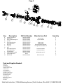
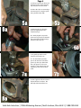
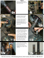
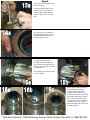
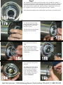
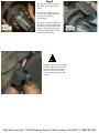
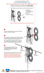
SpynTec
Solid Axle Industries
Installation Instructions for the
Dodge SpynTec Hub Conversion Kit
2000-Current
Solid Axle Industries | 12356 Mahoning Avenue | North Jackson, Ohio 44451 | 1.888.290.AXLE
Page 1
Warning - Installation should only be performed by a professional mechanic.
During the installation of the Spyntec front hub conversion kit, always ensure the
vehicle is properly supported and prevented from rolling. Do not use a jack to
support the vehicle. Always use properly rated jack stands in good working order.
Make sure all vehicle work is performed on a hard, level, and stable surface. An
unstable vehicle can fall and can kill or injure you.
Always wear proper safety gear. Debris can fall from the vehicle as well as tools
failing. Wear your safety goggles.
For all fastener torque values and disassembly proceedures, refer to the Jeep
Service Manual. These are available from your Jeep dealership. Torque values and
disassembly / assembly pictures shown are only for reference.
Before starting inspect that the length of stud supplied is long enough for the
wheels chosen. Thread engagement should be at least equivalent to the diameter
of the stud.
As always, re-torque lug nuts to manufacturers’ specifications after 50 miles. It’s
also a good preventative measure to do so after heavy off roading.
SOLID AXLE PRODUCTS
LIMITED LIFETIME MATERIAL AND WORKMANSHIP WARRANTY
Solid Axle Industries, LLC warrants to the original purchaser that the Solid Axle Products covered by this Warranty as specified below to be free
from defects in materials and workmanship under normal off road uder this Warranty shall be limited to the repair or exchange of any part or parts which
may thus prove defective under normal off road use and service by the original purchaser, and which our examination shall disclose to our satisfaction to be
thus defective. In order to claim the Warranty, you must return the parts in question, shipping charges prepaid, to Solid Axle at the address given below or a
factory authorized servicing distributor, together with your name, address, telephone number, a brief description of the defect and your proof of original
retail purchase for each product returned for warranty service. Exclusions from this Warranty are those specified below. Only products which are sold
bearing the “Solid Axle” trademark are covered by this Warranty. Products or components expressly excluded below are not covered by this Warranty. If the
product or component has been damaged by use in racing competition or by accident, abuse, collision, overloading, misuse, misapplication, improper
installation, improper service or modification of the product without written permission from Solid Axle, it is not covered by this warranty.
Except as expressly stated herein, there are no other warranties, expressed or implied, including implied warranties of merchantability
and fitness for a particular purpose. Any implied warranty of merchantability or fitness for a particular purpose which by law may not be excluded
is limited in duration to one (1) year from the date of original retail purchase of the product.
The Warranty and the remedies set forth above are exclusive and in lieu of all others, oral or written, expressed or implied. No Solid Axle
dealer, agent or employee is authorized to make any modification, extension or addition to this Warranty.
In no event is Solid Axle responsible for special, incidental or consequential damages resulting from any breach of Warranty, or under any other
legal theory, including, but not limited to, lost profits, down time, goodwill, damage to or replacement of equipment and property, loss of use of the p6oduct
of any associated equipment, or cost of substituted products.
The above exclusion or limitation may not cover you because some states do not allow the exclusion or limitation of incidental or consequential
damages or limitations on how long an implied warranty lasts. This Warranty gives you specific legal rights and you may also have other rights that vary from
state to state.
Solid Axle reserves the right to change Product design without notice or obligation to modify previously manufactured products.
Warranty Claims and Products returned for warranty service should be sent to:
SOLID AXLE INDUSTRIES, LLC
12356 Mahoning Avenue
North Jackson, Ohio 44451
(330) 538-9791
Coverage and Exclusions to this Warranty
Exclusions to this warranty:
Finish, u-joints, seals, bearings, rotors, studs
Products covered by this warranty:
SpynTec Hub Conversion Kit
Solid Axle Industries | 12356 Mahoning Avenue | North Jackson, Ohio 44451 | 1.888.290.AXLE
Page 2
M
L
A
Key
A
B
C
D
E
F
G
H
I
J
K
L
M
B
Description
35 Spline Stub Shaft
Mud Slinger
Inner Spindle Bearing Kit
Spindle
Inner Wheel Bearing
Inner Wheel Race
Hub Seal
V Lip Seal
Hub
Outer Wheel Bearing
Outer Wheel Race
Spindle Nut Kit
Lockout Hub Assembly
Factory ABS Sensor
Wheel Stud
C
D
F
E
SAI Part Number
SAI 030.20.004.03
SAI 030.20.005.01
SAI 030.20.006.01
SAI 050.20.001.05
SAI 050.20.003.10
SAI 050.20.003.11
SAI 050.20.003.14
SAI 050.20.003.15
SAI 050.20.002.09
SAI 050.20.003.12
SAI 050.20.003.13
SAI 050.20.005.01
SAI 050.20.020.01
Reuse
SAI 050.00.004.01
G
H
I
Manufacturer Part
Spicer 37308
Spicer 700014X
Timken 387A
Timken 382A
Chicago Rawhide CR29887
Chicago Rawhide CR401100
Timken LM104949
Timken LM104911
Mile Marker 459 S/S
Dorman 610-471
J
K
Quantity
2
2
2
2
2
2
2
2
2
2
2
2
1
2
16
Tools and Supplies Needed:
Floor Jack
Jack Stands
5 mm Hex Wrench
14 mm 12 Point Socket
18 mm Socket
1-11/16 Socket
Deadblow Hammer
Flat Blade Screw Drivers
Grinder or Belt Sander
Spindle Nut Socket
Snap Ring Pliers
Wheel Bearing Grease
Emery Cloth
Anti Seize
Solid Axle Industries | 12356 Mahoning Avenue | North Jackson, Ohio 44451 | 1.888.290.AXLE
1a
Page 3
1a- After the wheel is unbolted, the
brake caliper will need to be
removed. A 18 mm socket or
wrench will be needed.
1b -The factory rotor can now be
removed.
1b
Brake pads may contain asbestos. DO NOT
use compressed air. Use a readily available
brake cleaning fluid.
Asbestos has been found to be a cancer
causing agent.
2a
3a
2a -Next, a 1-11/16 socket and
ratchet will be required to remove
the axle nut, you will see four 6 or
12 point screws clamping the unit
bearing to the knuckle. Carefully
remove these (18 mm 6 point or
14 mm 12 point socket) as they
will be reused during re-assembly.
Sometimes a slight tap on the
socket will ensure proper seating
for 12 point spindle screws.
Us a 5 mm hex key to remove the
screw from the sensor, but do not
remove the sensor at this time as
it may be damaged. Carefully tap
on the unit bearing to seperate it
from the knuckle. Pay close
attention to not ruin the metal
dust shield as this will be reused.
Once the bearing is seperated
from the knuckle, remove the
sensor by pulling it straight out.
SEE NOTE ON PAGE 8
4a
2b
3b
With the sensor removed the
shaft assembly can now be
removed.
4a -Clean the knuckle bore and
surface with fine emery cloth or a
brush to remove any scale.
Solid Axle Industries | 12356 Mahoning Avenue | North Jackson, Ohio 44451 | 1.888.290.AXLE
Page 4
5a -Using a small screw driver and
hammer, tap the ujoint retaining
clips from the inner axle shaft.
5b -Once the clips are removed go
ahead and press or tap the ujoint
the u-joint from the shaft.
6a
5a
5b
6a -Remove the caps from the
ujoint and lightly grease the
needle bearings.
6b - Gently align the cap to the
ujoint cross paying close attention
not to move the needle bearings
from the wall of the cap.
6b
7a -A gentle tap with a small
hammer will seat the cap.
7b - Go ahead and repeat the
process for the other side of the
ujoint. Tap the caps down until
the c-clip groove can be seen.
Snap the c-clip onto the cap and
repeat the process for the inner
shaft.
7a
7b
8a -Put a light coat of anti-seize on
the knuckle face and bore. This
will help with removal later on.
8a
Solid Axle Industries | 12356 Mahoning Avenue | North Jackson, Ohio 44451 | 1.888.290.AXLE
Page 5
9a/9b -The assembled shafts can
be greased at the seal surface and
slid into the housings.
10a
9a
9b
10a -Slide the V lip Seal over the
mud slinger as shown. Apply a
thin film of grease on the lip.
10b -Slide the thrust washer with
the chamfer side toward the
center of the vehicle. This will sit
flat up against the shaft. If
installed incorrectly, there will be a
gap between the thrust washer
and the shaft.
10b
11a -Slide on the factory brake
dust shield and pilot the spindle in
the knuckle. Route the ABS sensor
through the metal dust shield.
11a
11b - Install the sensor BEFORE the
spindle is completely seated in the
knuckle. Ensure once again that
the routing of the cable will not
get cut on the bracket. The sensor
will be a tight fit into the spindle.
Make sure the sensor hole is
alligned with the tapped hole.
11b
12a/12b -Cut the screws back by
approximately 3/8 of an inch. The
final measurement from the
backside of the screw head to the
end of the screw should be around
1.80 inches.
12a
12b
Solid Axle Industries | 12356 Mahoning Avenue | North Jackson, Ohio 44451 | 1.888.290.AXLE
13a
14a
Page 6
13a -Anti seize the spindle screws
before installing.
Hand thread the knuckle screws
and work your way around in a
circular pattern tightening them
evenly. Tighten the screws to 85
ft-lbs.
14a -The v-lip seal is installed on
the hub from our factory. Put a
thin film of high quality grease on
the lip of the v-lip seal.
15a -Slide the hub and rotor
assembly onto the spindle. Pay
close attention that the inner hub
bearing seats against the shoulder
on the spindle.
15b -Push the outer wheel bearing
onto the spindle.
16a
15a
16b
16c
15b
Before going into the installation
of the spindle nuts onto the
spindle. Look closely at the
configurations to the left. 16a
shows the nut with the pin facing
toward the outside of the vehicle.
This is so the tab washer in 16b
can lock the nut in place keeping
in from turning. 16c is simply a
jamb nut pinching the nut washer
assembly together.
Solid Axle Industries | 12356 Mahoning Avenue | North Jackson, Ohio 44451 | 1.888.290.AXLE
Page 7
16d- Thread the inner spindle nut onto the spindle. Using a spindle nut socket and
torque wrench, tighten the spindle nut (photo 16a) to 50 ft-lbs. Do not over tighten the
nut. Rotate the hub back and forth while tightening. Back off the spindle nut 1/4 turn.
Slide on the lock washer (photo 16b). Make sure the pin is aligned with a hole on the
nut. Thread the outer nut onto the spindle and torque to 125 - 150 ft-lbs.
There should be no endplay in the assembly at this point. If there is, repeat the process.
16d
17a
17a -Slide the lockout hub body
into the wheel hub. You may have
to slightly rotate the hub to get
the splines located.
17b -Install the large snap ring into
the groove in the wheel hub.
17b
18a -Install the spacer onto the
shaft.
18b -Install the axle snap ring
using snap ring pliers. A pry bar
may have to be used from the
backside of the knuckle to shift the
shaft forward.
18a
18b
19a -Lay the large o-ring onto the
hub body.
19a
19b -Lightly grease the o-ring on
the hub dial body. Set the dial in
the free position and align the
holes in the dial to the tapped
holes in the hub body. Slide the
orings on the hex screws and
torque to 25-30 in-lbs.
19b
Solid Axle Industries | 12356 Mahoning Avenue | North Jackson, Ohio 44451 | 1.888.290.AXLE
Page 8
20a -Slide the rotor onto the face
of the hub. Make sure it is fully
seated.
20b -Slide the caliper assembly
over the rotor. Tighten the caliper
mount screws to factory
specifications.
20a
The Spyntec assembly is complete
at this time. You are ready to place
the wheel on and torque down the
lugnuts. Make sure you retorque
the lugnuts after 50 miles as well
as after heavy offroading.
20b
Warning - If your sensor has pulled
out of it’s protective plastic cover,
the sensor needs replaced with a
new one. Failure to do so will
result in a malfuction of the ABS
system.
Solid Axle Industries | 12356 Mahoning Avenue | North Jackson, Ohio 44451 | 1.888.290.AXLE