1
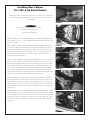
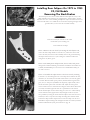
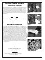
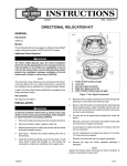
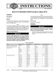
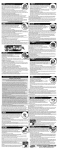
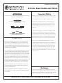
Installation Instructions
4 PISTON BRAKE CALIPERS
AND
ROTORS
Important Notice
ATTENTION
Statements in these instructions that are preceded by the following
n
words are of special significance:
Before installing a caliper or rotor kit, read through these instruc-
tions completely; this will familiarize you with the way in which the
parts fit together and the tools needed to complete the job.
Warning
This means there is the possibility of injury to
yourself or others.
n
In the course of installing these kits you will be replacing the
stock brake caliper(s) and/or rotor(s) with a high-performance
brake caliper. Please pay special attention to the section of the
Caution
instructions dealing with the centering of the caliper over the
brake rotor.
This means there is the possibility of
damage to the motorcycle.
n
Note
PM products are design to use both DOT 4 and DOT 5 brake
fluid, please use the manufactures suggested brake fluid. Never
Information of particular importance
has been placed in italics.
reuse brake fluid, Never mix DOT 4 and DOT 5 brake fluid, don’t
use brake fluid that you are not sure is new and clean. This installation should only be attempted by a mechanic with a thorough un-
WARRANTY
derstanding of and experience with motorcycle hydraulic systems.
n
Performance Machine Inc. warrants to the original purchaser
that the parts of this Brake Kit to be free of manufacturing
defects in materials and workmanship for a period of one (1)
year from the date of purchase. In the event warranty service is
required,you must call Performance Machine immediately with
a description of the problem.
If you plan on using the stock brake line/hose that runs
between the master cylinder and the caliper, then you will be just
switching the line at the caliper’s banjo fitting. We recommend
that you do not disconnect the line from the stock caliper until
you have the new caliper bolted in place and are ready to bleed
the brake system. This way the brake fluid will not run completly out of the master cylinder before you have the new caliper
If it is deemed necessary for Performance Machine to make an
evaluation to determine whether the part is defective,[a return
authorization number will be given by Performance Machine].
The parts must be packaged properly so as to not cause further
damage and returned prepaid to Performance Machine with a
copy of the original invoice of purchase and a detailed letter
outlining the nature of the problem. If after the evaluation by
Performance Machine the part was found to be defective it will
be repaired or replaced at no cost to you. If we replace it,we
may replace it with a reconditioned one of the same design.
conected up to it.
Performance Machine shall not be held liable for any consequential or incidental damages resulting from the failure of a
Performance Machine part.
Disclaimer
Performance Machine shall have no obligation if a part becomes defective as a result of improper installation, modification or abuse.
6892 Marlin Circle, La Palma, CA 90623
Rev. 4-15-08
These Performance Machine parts are designed for high performance motorcycle applications and are intended for the very experienced rider only. The installation of these Performance Machine
parts may adversely affect or void your factory warranty.
n
Phone 714-523-3000
n
FAX 714-523-3007
Harley Davidson is a registered Trademark of the Harley Davidson Motor Company
Front Caliper(s)
Performance Machine makes calipers designed to fit most 1978 and later
Harley-Davidson® front fork/wheel assemblies.
For a complete listing of brake caliper kits and brake rotor applications, see page 11
of this manual.
Caliper Finish
Caliper kits are available in a standard clear anodized, polished or chrome finish Make
sure that your caliper kit has the correct finish on it before you start to install it;
you cannot return it for incorrect finish once it has been installed.
XL & FXLR W/WIRE WHEEL ’87 UP
PN 1219-0017
Preparation
Before starting to assemble a PM caliper kit on your motorcycle, check the packing list
to make sure that the kit you re c e i ved is the correct one for yo u r model motorcycle. Have a new bottle of manufactures suggested brake fluid on hand.
Dual Disc Models
On motorcycles that have dual disc front brakes, it is recommended that you install the
calipers one at a time and bleed the air out of the brake system on the side with the
new caliper before installing and bleeding the second caliper. Installing and bleeding
the calipers in this manner will make the brake system easier to bleed.
XL-FXR-FXST-FLST- FLH ’84 UP PN
1213-0018 (DUAL DISC)
FXSTS Softail Springer
For detailed instructions for FXSTS models see page 4.
Removing The Stock Caliper
(except FXSTS)
Loosen brake line at caliper (do not remove) and retighten using minimum effort to
keep line from leaking. This makes line removal easier once the caliper is removed
from fork leg.
FXSTS ’88 UP
PN 1217-0017
Using a 5/16” hex wrench,remove the two mounting bolts from the stock caliper.
Remove the caliper from the fork legs. On ’84 and later calipers, reinstall the lower
mounting bolt into the stock caliper; this will keep the outer brake pad carrier from
falling out. Using a short piece of wire,hang the stock caliper from the handlebars, up
out of your working area.
XL-FX ‘78 THRU ’83 (10” DISC)
PN 1208-0017
Installing The Front Caliper (except FXSTS)
Note
Before installing your new PM caliper, check the brake rotor for wear and
flatness; use an appropriate straight edge. If the rotor is worn or warped,
replace it with a new one prior to installing this caliper.
CALIPER MOUNT 1984 & UP
’84 and later models: slip the PM caliper mount behind the mounting bosses
PHOTO 1
on the fork leg.Attach it using 2 ea. 3/8-16X1” socket head cap screws, with a drop of
Loctite #242 (blue) on their threads,and 2 ea.3/8” aluminum flat washers. Torque the
bolts to 20 ft.lbs, see Photo 1.
CALIPER MOUNT 1978-1983
’78 thru ’83 models: slip the PM caliper mount on the outside of the upper
PHOTO 2
mounting boss and on the inside of the lower mounting boss. Attach it to the top fork
boss using a 3/8-16 x 1 3/4” socket head cap screw, one 3/8”x.187” spacer (the spacer
fits between the mounting bracket and the boss on the fork leg) & a 3/8 lock nut. Use a
3/8-16 x 1 1/2” socket head cap screw, one 3/8” x .187” spacer (the spacer fits between
the boss on the fork leg and the mounting bracket) and a 3/8 lock nut.Torque the bolts
to 20 ft. lbs,see Photo 2.
Installing The Caliper
Slide the caliper down over the rotor and attach it to the mount with two 3/8-16 x 1
1/8” socket head cap screws,two 3/8” lock washers and two 3/8” flat washer. Tighten
these screws finger tight at this time, see Photo 3.
Centering The Caliper
PHOTO 3
PHOTO 4
After you have installed the new PM brake caliper onto your motorcycle you must align
its center to the center of the brake rotor; otherwise you will not get maximum brake
performance or brake pad wear. The center line of the caliper is where the two halves
of the caliper are joined together, see Photo 4. Look down from the top of the
caliper onto the rotor; if it is off-set to the outside then you will need to install
mounting bolt shims. The caliper shim kit that is included in the caliper kit contains 6
shims: 2ea. .016”,2ea .032” and 2ea .062”. These shims are to be inserted between the
mounting boss on the fork slider/rear caliper mount and the caliper’s mounting boss
to position the caliper so that its center line is over the rotor’s center line. To install the
shims, remove the caliper mounting bolt, slip the shim into place and replace the mounting bolt, see Photo 5. Check the caliper for centering at both ends; on most installations
the same thickness of shim will be needed behind each mounting boss.
After the caliper is centered over the rotor, install the lock washers from the kit and
torque the caliper mounting bolts to 22 ft.lbs.
W a r n i n g
PHOTO 5
Failure to center the brake caliper over the brake rotor will impede the performance of
the brakes. Rotate wheel slowly and with wheel raised, check for possible interference
between caliper, wheel and disc assembly. After brake is bled, check for free rotation
before and after master cylinder is activated.
FXSTS Softail Springer
B
To install the PM brake kit on the Springer front fork, you must remove the front wheel
assembly and raise the motorcycle on a suitable lift until the front is off the ground.
A
C
Warning
Center the motorcycle on the lift so that it will not fall
while you are working on it.
PHOTO 1
Photo 1:1) Loosen brake line and remove the 2 bolts at A, lift the caliper up
B
off the rotor and use a short length of wire to hang it from the handle-bars, up out of
your way.2) On the 3/8” bolt at B, remove the cotter pin from the rear, unscrew the locknut, unscrew the bolt from the threaded bushing in the fender mount and pull it out of
the caliper mount and reac-tion link. On ’93 and later models, use a piece of wire to hold
the fender up out of your way. 3) Unscrew the axle nut, C, slide the axle out of the fork
and lower the wheel to the ground.4) Remove the caliper mount from the wheel hub.
A
PHOTO 2
Photo 2: The Springer uses a combination axle seal and caliper mount bushing, with a wavy-washer and bronze thrust washer behind the caliper mount, A; remove
and discard the bronze thrust washer. The PM mount has this thrust washer built-in, B.
Install the PM caliper mount on the axle seal caliper mount bushing and raise the wheel
assembly up into the fork.
Slide the axle part way into the fork/wheel to hold it in place.
A
PHOTO 3
Photo 3: Install the outer caliper mount thrust washer, A, between the caliper
mount and the lower fork rocker. This is a factory part that was on the fork assembly;
the copper colored side faces the caliper. Slide the axle through the fork, install the flat
washer and axle nut; tighten the axle nut to 65 ft.lbs.
Photo 4: Remove the 2 end bolts from the caliper body, slip the caliper over the
A
rotor and install the 5/16 x 1 3/4” socket head bolts and flat washers, A, to attach it with.
Photo 5: Slide the 3/8-16 x 2 1/2” socket head bolt, A,through the caliper
mount, reaction link, flat washer, fender mount and thread it into the fender mount bushing. Install the lock-nut and cotter pin.
PHOTO 4
A
Note
Before the caliper is tightened down, it must be centered over the rotor;
see page 3 for the proper procedure.
PHOTO 5
Installing Brake Rotors
Performance Machine makes several different styles of brake rotors for
Harley-Davidson motorcycles. The rotors all install in one of two ways:
A) With counterbored bolts that attach the rotor by screwing directly into the hub
of cast wheels.
B) With counterbored bolts and lock-nuts that attach the rotor to the hub flange of
wire wheels.
Note
PHOTO 1
11.5” One Piece Rotor PN 0131-1518
Bolt Set PN 0109-0014-CH
Front and rear brake rotors are not the same. Front brake rotors use
5/16” bolts and rear brake rotors use 3/8” bolts.
Photo 1: A rear brake rotor (PN 0131-1518) and 3/8-16 Torex head bolts and
lock-nuts (PN 0109-0014-ch) needed to attach it to a stock Harley-Davidson wire wheel.
Brake rotor mounting bolts arenot included with PM brake rotors, they must be purchased
separately. See PM catalog.
Photo 2: A rear wire wheel, with the stock brake rotor removed. Make sure that
the mounting surface of the hub is clean and free of nicks or burs; smooth the hub flange
with a flat file if necessary.
PHOTO 2
Photo 3: The brake rotor should slip into place on the wheel hub with no more
than firm hand pressure. If the rotor will not go over the hub, check the hub for burs and
dress any down with a flat file. Do not force the rotor onto the hub. Make sure that the rotor is all the way down on the hub before installing or tightening any mounting bolts.
Photo 4: Insert the rotor mounting bolts through the rotor and into the hub. On
cast wheels they screw directly into the wheel, on spoke wheels lock-nuts are screwed onto
the bolts from the rear of the wheel hub flange.
PHOTO 3
1
If you are using chrome plated hardware, put a drop of Loctite #242 (blue)
on the bolt threads to keep them from galling the threads in the wheel or
lock-nuts.
4
2
3
Note
Torque the mounting bolts down in a “star”pattern,as shown in Photo 4.
Torque specs: 5/16” bolts to 16-19 ft.lbs.;3/8” bolts to 23-27 ft.lbs.
5
PHOTO 4
Rear Caliper Kits
Performance Machine 4 piston rear brake caliper kits are engineered to fit specific
Harley-Davidson models.The mounting brackets are designed for ease of installation
and maximum brake performance. Before starting the installation of this caliper kit,
make sure it is the correct one for your motorcycle and your brake rotors.
Note
PM makes separate caliper kits to fit 2 different rotor thicknesses:
SOFTAIL BRAKE SYSTEM: PN 1274-0059
11.5” X .275” ROTOR: PN 0131-1518
A) Calipers for .200”-.225” thick rotors which fit the stock Harley Davidson rotors, the PM Image 11.5” x .225” rotors and the PM 11.5”x .200 full-floating rotors with the stainless steel outer section. The part number of these calipers
are 0052-2400, 0052-2400-P, 0052-2400-CH.
B) Calipers for .275” thick rotors which fit PM 11.5” x .275” standard
one-piece cast iron rotors and the PM 11.5” x .275” full floating rotors with
the cast iron outer section. The part number of these calipers are 0052-2401,
0052-2401-P, 0052-2401-CH.
FXD (DYNA) BRAKE SYSTEM: PN 1279-0059
11.5” X .275” ROTOR: PN 0131-1518
For a complete listing of brake caliper kits and brake rotor applications,
see page 11 of this manual.
Caliper Finish
Caliper kits are available in a standard clear anodized, polished or chrome finish. Make
sure that your caliper kit has the correct finish on it before you start to install it; you
cannot return it for incorrect finish once it has been installed.
FX BRAKE SYSTEM: PN 1268-0059
11.5” X .275” ROTOR: PN 0131-1518
Special Installation Notes
To install a PM rear brake caliper and/or brake rotor, you will be removing the motorcycles rear wheel assembly. Please be aware that the reinstallation of the rear wheel
assembly will require the alignment of the wheel in the motorcycles frame and the
correct tensioning of the drive belt/chain. You will need the service manual for your
model motorcycle for the complete instructions on the correct proceedures to do these
adjustments.
1973-1984 BRAKE SYSTEM: PN 1255-0059
11.5” X .275” ROTOR: PN 0131-1518
Installing Rear Calipers On FXR, FXWG,
FXD & FL Models
Removing The Stock Brakes
The basic steps are the same to install a PM rear bra ke caliper kit on any of the late
model Harley Davidson “swingarm”style motorcycles; all require the removal of the
rear wheel. Using a suitable lift, raise the motorcycle high enough off the ground to allow you to remove the rear wheel assembly.
PHOTO 1
W a r n i n g
Center the motorcycle on the lift so that it will
not fall while you are working on it.
Photo 1: Loosen brake line at caliper. Remove the rear brake caliper assembly
PHOTO 2
by unscrewing the 2 caliper mounting bolts that go through the caliper into the caliper
mounting bracket. Lift the caliper up and off the mounting bracket and brake rotor,
fold the caliper back out of your working area. Don’t remove the brake line from the
caliper yet; you will do this just before you are ready to hook it up to the new caliper.
The brake pads are held into the caliper mounting bracket by 2 spring clips; slide the
brake pads out of the mounting bracket and remove the retaining springs. Loosen the
axle adjuster nuts and remove the rear wheel assembly.
Remove the stock caliper mounting bracket. Clean the inside of the swingarm of any
dirt or grease.
Photo 2: Slide the PM caliper mounting bracket into position on the swingarm. The brackets for the FX, FXR and FL models fit over the swingarm tube and the
bracket for the FXD Dyna fits onto a lug that is welded onto the inside surface of the
swingarm. Make sure that the brack-et slides all the way onto the swingarm; remove
any nicks or burs that keep the bracket from seating on the swingarm.
PHOTO 3
Photo 3: Raise the wheel up into position with the drive belt/chain on the
rear sprocket; slide the axle through the swingarm, the axle spacer (from the caliper kit,
if a spacer other than the stock one is needed), the caliper mount,the wheel and any
axle spacers that were used on the drive side of the wheel.
Photo 4: Adjust the wheel, per the service manual so that it is centered in
the swingarm and so that the drive belt/chain is correctly tensioned. Mount the PM
caliper onto the bracket using the 3/8-16 X 1” button head cap screws; tighten them
only hand tight. Check for any clearance problems by rotating the wheel. Center the
caliper per instructions on page 3 and install the brake line and bleed the system per
instructions on page 10.
PHOTO 4
Installing Rear Calipers
On 1987 & Up Softail Models
Installing a rear caliper requires the removal of the rear wheel. Using a suit-able lift,
raise the motorcycle high enough off the ground to allow you to remove the rear
wheel assembly.
PHOTO 1
W a r n i n g
Center the motorcycle on the lift so that it will
not fall while you are working on it.
Loosen brake line at caliper.
Photo 1: Remove the stock rear brake caliper, rear wheel and caliper mount
per instructions on page 7 — photo 1. Slide the PM caliper mounting bracket onto the
lug on the swingarm.
Photo 2: Raise the wheel up into position in the frame, slip the drive belt
PHOTO 2
onto the rear pulley, slide the axle through the swingarm, the caliper mount, the axle
spacer, the wheel and the axle spacers that were used on the drive side of the wheel.
Next, with the axle adjuster screws loosened up as far as they will go, slide the wheel
assembly as far forward as it will go. You need to do this to allow for clearance to
install the caliper mounting bolts.
Photo 3: Set the caliper onto the mounting bracket and over the rotor and
attach it with two 3/8-16 X 1”button head cap screws; tighten the screws only hand
tight at this time. Slide the wheel into its normal operating position, tighten up the axle
nut and check the centering of the caliper over the rotor. Measure the caliper’s offset
from the rotor’s centerline and setup the amount of shims needed to correct it. Next
loosen the axle nut, slide the axle forward, remove the caliper mounting bolts and
insert the shims between the caliper and the caliper mount. Reinstall the caliper mounting bolts with 3/8”star lock washers and tighten the bolts to 25 ft.lbs.
PHOTO 3
Photo 4: Adjust the wheel, per the service manual so that it is centered in
the swingarm and so that the drive belt is correctly tensioned. On the bottom of the
caliper mount is a hex head bolt and jam nut that clamps the mount to the lug on the
swingarm, tighten this bolt up to 10 ft. lbs. Next, tighten the jam nut onto the caliper
mount. This bolt and jam nut takes the place of the rubber stopper used on the stock
caliper mount.
Photo 5: Remove the end of the brake line from the stock caliper; you will
PHOTO 4
need a 3/8”12 point socket wrench or box end wrench to remove the banjo bolt from
the stock caliper. Attach the end of the brake line to the new PM caliper using the PM
supplied seal washers, one washer goes on each side of the banjo fitting; apply a dab
of grease to the washers to prevent leaks. Lastly, bleed the brake system as described
on page 10.
PHOTO 5
Installing Rear Calipers On 1973 to 1983
FX, FLH Models
Removing The Stock Brakes
The basic steps are the same to install a PM rear brake caliper kit on any of the
Harley-Davidson motorcycles that are equipped with a “banana caliper”, whether
they have 10”or 11.5” rotors. Installing the caliper kit requires the removal of the rear
wheel.You will need to use a suitable lift to raise the motorcycle high enough off the
ground to allow you to remove the rear wheel assembly.
A
PHOTO 1
W a r n i n g
Center the motorcycle on the lift so that it will
not fall while you are working on it.
Loosen brake line at caliper.
A
Photo 1: Remove the rear wheel by loosening the axle adjuster nuts,
remove the lower caliper bracket to strut bolt at A, unscrew the axle nut and
remove the axle, lower the rear wheel assembly down to the ground and swing
the caliper and its mount out of your working area. Clean the inside of the
swingarm of any dirt or grease.
B
PHOTO 2
Photo 2: The PM 4 piston caliper mount; the rear wheel axle passes
through hole A and the stabilizing strut attaches at hole B.Two size brackets are
available, PN 0024-0026CJ, for use with 10” rotors and PN 0024-1526CJ, for
use with 11.5”rotors
Photo 3: Assemble the caliper mount to the lower strut by inserting
1/2-20 X 1 1/2” bolt through the rear of the caliper mount and into the strut,
install the 1/2” flat washer, then the lock washer and the 1/2” lock-nut, tighten
to 45 ft.lbs. Raise the wheel up into position, install the axle through the swingarm, the 3/4” axle spacer (included in the caliper kit), caliper bracket, wheel
and the stock axle spacers used on the drive side. Adjust the wheel, per the
service manual so that it is centered in the swingarm and so that the drive chain
is correctly tensioned. Tighten the axle nut to specifications in the manual.
Mount the PM caliper onto the bracket using the 3/8-16 X 1” socket head cap
screws and lock washers; tighten them only hand tight. Check for any clearance problems by rotating the wheel. Check the caliper’s offset from the rotor’s
centerline; if there is any,remove the caliper mounting bolts and insert shims
between the caliper and the caliper mount to center the caliper over the rotor.
Reinstall the caliper mounting bolts and tighten the bolts to 25 ft.lbs., install the
brake line and bleed the system per instructions on page 10.
PHOTO 3
Completing The Brake Installation
Attaching The Brake Line
First tape handle bar master lever 1/2 way closed. This will prevent fluid from free flowing from hose. Remove the end of the brake line from the stock caliper; you will need
a 3/8” 12 point socket wrench or box end wrench to remove the banjo bolt from the
stock caliper. Working rapidly, so that an excessive amount of brake fluid does not run
out of the end of the brake hose, attach the end of the brake line to the new PM caliper
using the PM supplied seal washers, one washer goes on each side of the banjo fitting;
see Photo 1.
PHOTO 1
Note
Position the banjo fitting so that the brake hose does not rub on the front
fender or other part of the motorcycle.
Tighten banjo bolt to 10 ft.lbs. of torque.
Bleeding The Brake System
You will find it is easier to bleed the brake system if you have a helper. First, fill the master cylinder with manufactures suggested brake fluid and put the cover back on the master
cylinder. Attach a short length of rubber hose to the bleeder screw on the brake caliper,
see Photo 2; put the other end of the hose into a coffee can or other suitable catch can.
Have your helper pull in on the front brake lever or push down on the rear brake pedal
5 times, see Photo 3. At the end of the 5th stroke, have your helper hold the
brake lever in or pedal down. While the helper holds the lever/pedal, open the bleeder
fitting on the caliper, you will need a 1/4” end wrench for this. Air and brake fluid should
come out of the end of the hose that is connected to the bleeder fitting. After the air and
brake fluid have stopped coming out of the hose, close the bleeder fitting; your helper can
now release the brake lever/pedal. This action will force the air that is trapped in the brake
system out the bleeder screw, because the brake system can contain more air than you can
expel in one bleeding; you will need to repeat this procedure more than once. Check the
fluid level in the master cylinder after each bleeding, don’t let the master cylinder run dry
as this will push air back into the brake system which will require the bleeding procedure
to be started over again.
PHOTO 2
PHOTO 3
Note
Do not over tighten the bleeder screw.
W a r n i n g
Failing to bleed all the air out of the brake system will impede
the performance of the brakes.
COMPLETED FRONT BRAK E
CALIPER INSTALLATION