1
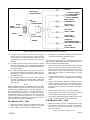
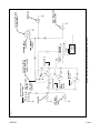
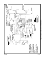
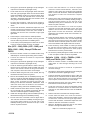
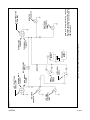
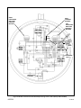
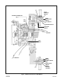
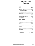
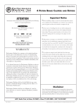
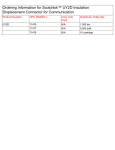
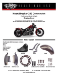
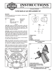
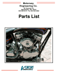
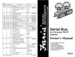
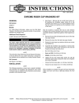
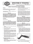
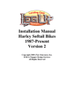
INSTRUCTIONS
®
REV. 7-1-95
-J00524
Kit Number 91860-88B
SELF-CANCELING TURN SIGNAL KIT
General
This kit is designed for use on the following motorcycles:
MODEL
FLTs
FLHs
FLHS's
Softails
FXWGs
XLs
FXEs
FXRs
FXRTs
MODEL YEARS
1980 - 1988 (Includes FLHS 1987 - 1988)
1972 - 1984
1981 - 1984
1984 - 1990
1980 - 1986
1975 - 1990
1975 - 1985
1982 - 1990
1983 1/2 - 1990
NOTE
This kit cannot be used on 1986 models that have the stock
“latching type” turn signal switches.
This kit contains the following components:
QTY
3
1
2
2
1
1
6
1
DESCRIPTION
Ring terminal
Connector, male-to-male, spade, insulated
Terminal, spade female
Cable strap
Module, turn signal
Wire harness
Connector, Scotchlok*
Vinyl conduit, 3/8 in. inside diameter x 34 in. long
Installation
General (All Models)
1WARNING
Module is designed to operate two lights and one
indicator at one time. More than two lights will create an
overload, causing the flashes to occur too fast to be
seen. Making a turn with a constantly lit turn signal
could confuse other motorists. Such confusion could
result in an accident and personal injury.
FLT Models (1980 - 1988)
1.
Remove outer fairing on FLHTs. See applicable Service
Manual for detailed instructions. FLT’s mounting location
and flasher are accessible without removing headlight
housing.
2.
Connect wire harness to module at 10 pin/socket
connector housings.
NOTE
On 1987 - 1988 FLHS models, mount the canceler module
in a suitable location using cable straps or a bolt through
mounting hole in module.
3.
Use cable straps to secure turn signal module to right
fork tube just above rubber fork stop. Ground black wire
to front fork bracket with ring ter minal or spade
connector on later models.
4.
Route wires from module up to area of four-way flasher
switch. Wires must be routed between top triple clamp
and flasher bracket, not over the top of flasher bracket.
5.
See Figure 2 (shows stock signal light circuit) and
Figure 3 (shows kit connected in signal light circuit).
Locate pink wire that connects to four-way flasher
switch. Cut wire near switch. Connect with Scotchlok*,
white/violet striped wire from module to pink wire going
to four-way flasher switch. Connect with Scotchlok*,
violet wire from module to remaining end of pink wire
leading into main wiring harness and connected to left
signal light switch.
6.
Locate tan wire leading to four-way flasher switch. Cut
wire near switch. Connect with Scotchlok*, white/brown
striped wire from module to tan wire leading to four way
flasher switch. Connect with Scotchlok*, brown wire
from module to remaining end of tan wire going to main
wiring harness and connected to right signal light
switch.
7.
Locate directional flasher unit. Disconnect wires to unit;
cut off 90 degree flag terminals and terminate wires with
female spade terminals. Obtain male/male spade
connector from kit, and connect flasher leads together
with this connector.
See Figure 1. The module connections are identical for all
models.
The installation on all models is similar; but, refer to the
specific installation procedure that covers the model on
which this kit is being installed. After the installation has
been completed, refer to “Operation Instructions.”
NOTE
The wire lengths of the harness leads and the length of the
vinyl conduit may be cut to the needed length for each
specific installation. To allow slipping the wires into the
conduit, it is recommended that all wires be cut to their
needed lengths before final connections are made.
1CAUTION
To avoid possibility of a short circuit, disconnect battery
(negative cable first) before performing any of the
following steps.
1 of 10
i00534-.tif
GROUND
FRONT VIEW
OPPOSITE WIRES
+12 VOLTS, CONNECT
TO SILVER TERMINAL
OF ACCESSORY
CIRCUIT BREAKER
REED SWITCH,
SPEEDOMETER
RED
WHITE/
BROWN STRIPE
BLACK
RIGHT TURN
SIGNAL LAMPS
WHITE/
GREEN STRIPE
LEFT TURN
SIGNAL LAMPS
GREEN
WHITE/
VIOLET STRIPE
VIOLET
RIGHT TURN
SIGNAL SWITCH
GROUND IF
SPEEDOMETER DOES
NOT HAVE REED SWITCH
BROWN
LEFT TURN
SIGNAL SWITCH
Figure 1. Required Connection For Turn Signal Canceler, All Models
8.
9.
Connect ring terminal on red wire lead from signal
module to silver (output) terminal on the accessory
circuit breaker. (On FLT/C and FLHS models, you must
remove instrument panel to locate accessory circuit
breaker.)
On 1986 and later models, locate white/green striped
wire from reed switch (under speedometer assembly)
and connect with Scotchlok* to white/green striped wire
from signal module.
10. On 1985 and earlier models, the green wire must be
grounded. Terminate green wire, from module, with ring
terminal from kit. Fasten ring terminal to vehicle at bolt in
top front fork bracket.
11. Cut off extra (unused) wire as close to rear of module
connector as possible. On 1985 and earlier, it will be the
green and white striped wire. On 1986 and later, it will be
the green wire.
NOTE
With the HAZARD switch in the “HAZARD” position, the stock
hazard flasher will provide the pulses for the 4-way lamp
operation. With HAZARD switch in the “OFF” position, the
turn signal module will control the turn signals and provide 4way or hazard light operation. To activate the modulecontrolled hazard lights, simultaneously press and hold the
right and left turn signal switches for 1 1/2 seconds. A
second simultaneous depressing of the right and left turn
signal switches will cancel the hazard lights.
2.
See Figure 2 (shows stock signal light circuit) and Figure
3 (shows kit connected in signal light circuit).
NOTE
The FLH wires have different color coding than that shown in
Figures 2 and 3. Make certain you are connecting the correct
wires as directed in the following steps:
3.
Locate violet wire from left signal light switch and brown
wire from right signal light switch at hazard flasher
switch. Cut violet and brown wires about 2-3 in. from
hazard switch. Connect with Scotchlok*, white/violet
striped wire from module to violet wire going to hazard
flasher switch.
4.
Connect with Scotchlok*, violet wire from module to
remaining end of violet wire connected to left signal light
switch.
5.
Connect with Scotchlok*, white/brown striped wire, from
module, to brown wire leading to 4-way flasher switch.
Connect with Scotchlok*, brown wire, from module, to
remaining end of brown wire connected to right signal
light switch.
6.
Perform Steps 7 and 8 of the FLT models procedure.
7.
Terminate green wire, from module, with ring terminal
from kit. Fasten ring terminal to a suitable ground.
8.
Cut off extra (unused) white/green module wire as close
to rear of 10-place module connector as possible.
FLH Models (1972 - 1984)
FLHS Models (1981 - 1984)
1.
1.
Mount the canceler module in a suitable location using
cable straps or a bolt through mounting hole in module.
Perform Steps 2 and 4 of the FLT models procedure.
Mount the canceler module in a suitable location using
cable straps or a bolt through mounting hole in module.
Connect wire harness to module at 10 pin/socket
connector housings.
Steps 2-8 continued on page 5 of 10
-J00524
2 of 10
i00535-.tif
INDICATOR
➤
LEFT REAR
TURN SIGNAL
LAMP
LEFT SIGNAL
SWITCH
Directional
flasher
CONNECTOR
HAZARD FLASHER
SWITCH SHOWN IN
“HAZARD” POSITION
Accessory
circuit
breaker
12 vdc
HAZARD
FLASHER
TURN SIGNAL
FILAMENT
RUNNING LAMP
FILAMENT
➤
➤
Figure 2. Stock Turn Signal Circuit with Hazard Switch and Flasher
➤
RIGHT
SIGNAL
SWITCH
➤
CONNECTOR
TURN SIGNAL
FILAMENT
RUNNING LAMP
FILAMENT
LEFT FRONT TURN
SIGNAL LAMP
➤
➤
➤
➤
➤
➤
➤
-J00524
INDICATOR
RIGHT FRONT TURN
SIGNAL LAMP
RIGHT REAR TURN
SIGNAL LAMP
➤
➤
➤
➤
3 of 10
INDICATOR
➤
NOTE 2. Wires shown with
double lines are part of self
canceling kit harness.
NOTE 1. On 1986 and later
models, connect W/GN on 10place connector to
speedometer reed switch and
cut off green wire close to 10place connector and ground
GN wire
LEFT REAR
TURN SIGNAL
LAMP
SPADE CONNECTOR
FROM KIT
➤
Directional
flasher
➤
10-PLACE
CONNECTOR
Accessory
circuit
breaker
12 vdc
CUT OFF
TERMINAL
HAZARD
FLASHER
CUT OFF
TERMINAL
1985 AND
EARLIER ➤
SEE NOTE 1.
CONNECTOR
CUT
WIRE
Figure 3. Turn Signal Circuit (Figure 2.) with Kit Harness Installed
➤
RIGHT
➤
SIGNAL
SWITCH
LEFT SIGNAL
SWITCH
CONNECTOR
TURN SIGNAL
FILAMENT
RUNNING LAMP
FILAMENT
➤
➤
RIGHT REAR TURN
SIGNAL LAMP
INDICATOR
RIGHT FRONT
TURN SIGNAL
LAMP
SEE NOTE 2.
➤
➤
➤
➤
➤
➤
➤
➤
LEFT FRONT TURN
SIGNAL LAMP
TO SPEEDOMETER RUNNING LAMP
FILAMENT
REED SWITCH ON
1986 AND LATER
MODELS.
TURN SIGNAL
SEE NOTE 1.
FILAMENT
HAZARD FLASHER
➤
SWITCH SHOWN IN
“HAZARD” POSITION
➤
➤
➤
➤
➤
i00536-.tif
➤
-J00524
➤
➤
4 of 10
2.
See Figure 4 (shows stock signal light circuit) and Figure
5 (shows kit connected in signal light circuit).
3.
Locate violet wire from left signal light switch and brown
wire from right signal light switch at main terminal block
inside the headlamp housing. Cut violet and brown wires
about 2-3 in. from main terminal block. Connect with
Scotchlok*, white/violet striped wire from module to violet
wire going to main terminal block.
4.
Connect with Scotchlok*, violet wire from module to
remaining end of violet wire connected to left signal light
switch.
5.
Connect with Scotchlok*, white/brown striped wire, from
module, to brown wire connected to main terminal block.
Connect with Scotchlok*, brown wire, from module, to
remaining end of brown wire connected to right signal
light switch.
6.
Perform Steps 7 and 8 of the FLT models procedure
7.
Terminate green wire, from module, with ring terminal
from kit. Fasten ring terminal to a suitable ground.
8.
Cut off extra (unused) white/green module wire as close
to rear of 10-place module connector as possible.
XLs (1975 - 1990), FXEs (1975 - 1985), and
FXRs (1982 - 1990) - Except FXLRs and
FXRTs
1.
Mount the canceler module in a suitable location using
cable straps or a bolt through mounting hole in module.
2.
Connect wire harness to module at 10 pin/socket
connector housings.
3.
See Figure 4 (shows stock signal light circuit) and Figure
5 (shows kit connected in signal light circuit).
4.
Locate an electrical ground location to which a #10 ring
terminal can be connected. Route the black and green
wires in the canceler harness to this ground location
and, if required, cut the wires to the correct length.
5.
Terminate black and green wire, from module, with ring
terminals from kit and connect to ground.
6.
Remove the headlamp from the headlamp housing. See
Figure 6. Locate the grommet (bushing) that secures the
main wire harness at back of headlamp housing. With a
pliers, gently compress the bushing and push the
bushing out to allow the white/violet, white/brown, violet
and brown wires from the module to be “threaded”
through the bushing and into the headlamp housing.
7.
Install conduit over these wires and cut to length so that
the conduit will butt up against the bushing after the
wires are installed through the headlamp housing.
8.
Install wires through bushing and into headlamp housing.
Reinstall the bushing into the headlamp housing.
9.
Find the violet wire connected to the left signal switch.
The violet wire enters the headlamp housing through a
right angle plastic bushing on the left side of the
headlamp housing and is connected to the pin or male
half of a 12-place connector.
10. Cut the violet wire about 2-3 in. from the 12-place
connector. Connect with Scotchlok*, violet wire from
module to end of violet wire connected to left signal light
switch. Connect with Scotchlok*, white/violet striped wire
from module to violet wire connected to 12-place
connector.
11. Find the brown wire connected to the right signal switch.
The brown wire enters the headlamp housing through a
right angle plastic bushing on the left side of the
headlamp housing and is connected to the pin or male
half of a 12-place connector.
12. Cut the brown wire about 2-3 in. from the 12-place
connector. Connect with Scotchlok*, brown wire from
module to end of brown wire connected to right signal
light switch. Connect with Scotchlok*, white/brown
striped wire from module to brown wire connected to 12place connector.
13. Locate directional flasher unit at bottom of headlamp
housing. Disconnect wires to unit; cut off 90 degree flag
terminals and ter minate wires with female spade
terminals. Obtain male/male spade connector from kit,
and connect flasher leads together with this connector.
14. Locate accessory circuit breaker on motorcycle. Route
the red wire from the module to the accessory circuit
breaker and connect ring terminal to silver (output)
terminal on the accessory circuit breaker.
15. Cut off extra (unused) white/green module wire as close
to rear of 10-place module connector as possible.
Softails (1984 - 1990), FXWGs (1980 1986), and FXLRs (1987 - 1990)
1.
Mount the canceler module in a suitable location using
cable straps or a bolt through mounting hole in the
module.
2.
Connect wire harness to module at 10 pin/socket
connector housings.
3.
See Figure 4 (shows stock signal light circuit) and Figure
5 (shows kit connected in signal light circuit).
4.
Locate an electrical ground location to which a #10 ring
terminal can be connected. Route the black and green
wires in the canceler harness to this ground location
and, if required, cut the wires to the correct length.
5.
Terminate black and green wire, from module, with ring
terminals from kit and connect to ground.
6.
Locate the connectors to which the handlebar switch
harnesses are connected. Route the white/violet and
violet wire on the module harness to the left handlebar
connector.
7.
Find the violet wire connected to the left signal switch.
8.
Cut the violet wire about 2-3 in. from the connector.
Connect with Scotchlok*, violet wire from module to end
of violet wire connected to left signal light switch.
Connect with Scotchlok*, white/violet striped wire from
module to violet wire connected to connector.
9.
Route the white/brown and brown wires on the module
harness to the right handlebar connector.
Steps 10-14 continued on page 9 of 10
-J00524
5 of 10
i00537-.tif
INDICATOR
SEE NOTE
LEFT REAR
TURN SIGNAL
LAMP
RIGHT
SIGNAL
SWITCH
INDICATOR
INDICATOR LAMP
(SINGLE)
Accessory
circuit
breaker
12vdc
Directional
flasher
TURN SIGNAL
FILAMENT
RUNNING LAMP
FILAMENT
Figure. 4. Stock Turn Signal Circuit (No Hazard Flasher)
LEFT SIGNAL
SWITCH
➤
TURN SIGNAL
FILAMENT
RUNNING LAMP
FILAMENT
LEFT FRONT TURN
SIGNAL LAMP
➤
➤
➤
➤
INDICATOR
SEE NOTE
RIGHT FRONT TURN
SIGNAL LAMP
RIGHT REAR
TURN SIGNAL
LAMP
NOTE. On motorcycles with only 1 indicator,
the lamp is connected across the left and
right circuit. The dotted circuit illustrates the
light connections.
➤
➤
➤
-J00524
➤
➤
➤
➤
➤
6 of 10
INDICATOR
LEFT REAR
TURN SIGNAL
LAMP
RIGHT
SIGNAL
SWITCH
➤
Accessory
circuit
breaker
12vdc
CUT OFF
TERMINAL
CUT OFF
TERMINALS
Directional
flasher
CUT
WIRE
➤
➤
INDICATOR
RIGHT FRONT TURN
SIGNAL LAMP
NOTE. On motorcycles with
only 1 indicator, the lamp
is connected across the
left and right circuits. The
dotted circuit shown on
Figure 4 illustrates the
light connections. Because
of limited space, the single
indicator circuit is not
shown in this Figure.
RIGHT REAR
TURN SIGNAL
LAMP
SPADE CONNECTOR
FROM KIT
TURN SIGNAL
FILAMENT
RUNNING LAMP
FILAMENT
10-PLACE
CONNECTOR
Figure 5. Stock Turn Signal Circuit (Figure 4.) With Kit Harness Connected
LEFT SIGNAL
SWITCH
➤
TURN SIGNAL
FILAMENT
RUNNING LAMP
FILAMENT
➤
LEFT FRONT TURN
SIGNAL LAMP
➤
i00538-.tif
➤
➤
➤
➤
➤
➤
➤
-J00524
➤
➤
➤
➤
➤
7 of 10
i00539-.tif
RIGHT
HANDLEBAR
SWITCHES
HARNESS
BUSHING
MAIN
HARNESS
BUSHING
LEFT
HANDLEBAR
SWITCHES
HARNESS
BUSHING
➤
➤
CUT
WIRE
➤
➤
➤
CUT
WIRE
➤
PIN
CONNECTOR
HALF
DIRECTIONAL
FLASHER
➤
Figure 6. Module Connections Inside Headlamp Housing On XL’s, FXE’s (Except FXLR & FXRT)
-J00524
8 of 10
10. Find the brown wire connected to the right signal switch.
11. Cut the brown wire about 2-3 in. from the connector.
Connect with Scotchlok*, brown wire from module to end
of brown wire connected to right signal light switch.
Connect with Scotchlok*, white/brown striped wire from
module to brown wire connected to connector.
11. Terminate black wire, from module, with ring terminal from
kit and connect to ground.
12. Locate directional flasher unit in fairing. Disconnect wires
to unit; cut off 90 degree flag terminals and terminate
wires with female spade terminals. Obtain male/male
spade connector from kit, and connect flasher leads
together with this connector.
12. Locate directional flasher unit. The flasher is located
under the instrument panel cover on Softail and FXWG
models and under fuel tank on FXLR. Disconnect wires to
unit; cut off 90 degree flag terminals and terminate wires
with female spade terminals. Obtain male/male spade
connector from kit, and connect flasher leads together
with this connector.
13. Locate accessory circuit breaker on motorcycle. Route the
red wire from the module to the accessory circuit breaker
and connect to silver (output) terminal on the accessory
circuit breaker.
13. Locate accessory circuit breaker on motorcycle. Route the
red wire from the module to the accessory circuit breaker
and connect ring terminal to silver (output) terminal on the
accessory circuit breaker.
14. Cut off (unused) white/green module wire as close to rear
of 10-place module connector as possible.
On motorcycles without a reed switch in the speedometer, the
tur n signal module will cancel the signal lights after
approximately 10 seconds of operation. If motorcycle has a
speedometer with reed switch: (1) the signal light “ON” time
will vary from 5 to 12 seconds, depending on vehicle speed;
(2) if vehicle is not moving, the signal lights will flash
indefinitely.
FXRT Models (1983 1/2 - 1990)
Turn Signal Operation
1.
Remove instrument panel from fairing following
instructions given in applicable Service Manual.
1.
To signal for a right turn, press and release the right turn
signal switch.
2.
Mount the canceler module in a suitable location using
cable straps or a bolt through mounting hole in module.
2.
To cancel signal, press and release the right turn signal
switch a second time.
3.
Connect wire harness to module at 10 pin/socket
connector housings.
3.
Left turn signals are activated by pressing the left turn
signal switch.
4.
See Figure 4 (shows stock signal light circuit) and Figure
5 (shows kit connected in signal light circuit).
4.
5.
See Figure 7. Locate violet wire from left signal light
switch and brown wire from right signal light switch at 12place pin connector half. The 12-place connector is
located in front of the steering head. Cut violet and brown
wires about 1-2 in. from pin connector half. Connect with
Scotchlok*, white/violet striped wire from module to violet
wire going to pin connector half.
If left turn signals are flashing and the right side turn
signal switch is pressed, the module will cancel the left
turn signals and begin flashing right turn signals. The
module will always respond to the last switch input.
6.
Connect with Scotchlok*, violet wire from module to
remaining end of violet wire connected to left signal light
switch.
7.
Connect with Scotchlok*, white/brown striped wire, from
module, to brown wire leading to pin connector half.
Connect with Scotchlok*, brown wire, from module, to
remaining end of brown wire connected to right signal
light switch.8. On 1986 and later models, locate
white/green striped wire connected to radio. (The
white/green striped wire was connected to speedometer
reed switch.) Connect with Scotchlok* to white/green
striped wire from signal module.
8.
9.
On 1986 and later models locate white/green striped wire
connected to radio. (The white/green striped wire was
connected to speedometer reed switch). Connect with
Scotchlok® to white/green striped wire from signal
module.
On 1985 and earlier models, the green wire must be
grounded. Terminate green wire, from module, with ring
terminal from kit. Fasten ring terminal to a vehicle
electrical ground.
Operation Instructions
General
NOTE
If turn signal switch is depressed and held, the turn signal will
flash indefinitely. If the rider prefers a longer time or distance
(with turn signals “ON”), the turn signal switch can be held in
longer and released closer to the intersection. For a shorter
time or distance (with turn signals “ON”), press the switch a
second time to cancel the turn signals.
Hazard Light (4-Way) Operation
1.
To activate the module-controlled hazard lights,
simultaneously press and hold the right and left turn
signal switches for 1 1/2 seconds.
2.
A second simultaneous depressing of the right and left
turn signal switches will cancel the hazard lights.
NOTES
● The turn indicator light, on models that have only one turn
indicator light, will not flash while the hazard flasher is
operating.
● Motorcycles that are equipped with stock hazard flasher
and circuitry will have the following two methods of activating
the hazard or 4-way lights:
a.
b.
Place HAZARD switch in “HAZARD” position.
See Steps 1 and 2 above.
10. Cut off extra (unused) wire as close to rear of module
connector as possible. On 1985 and earlier, it will be the
green and white striped wire. On 1986 and later, it will be
the green wire.
-J00524
9 of 10
i00540-.tif
RADIO
FUNCTION
SWITCH
ANTENNA CONNECTOR
➤
➤
CUT
WIRE
➤
➤
➤
RIGHT
DIRECTIONAL
SWITCH
KILL SWITCH
STARTER SWITCH
➤
STOPLIGHT
SWITCH
TO
MODULE
CUT
WIRE
➤
TO MODULE
HORN
SWITCH
DIMMER SWITCH
LEFT
DIRECTIONAL
SWITCH
➤
➤
➤
➤
RADIO
VOLUME
CONTROL
Figure 7. Module Connections For FXRT Models
-J00524
10 of 10