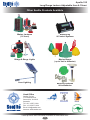
1
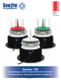
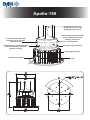
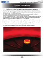
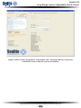
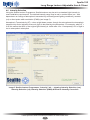
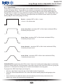
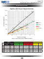
Apollo-155
Long Range Lantern Adjustable from 4-12nm+
Programming, Installation & Service Manual
Version 1.3
Apollo-155
Integrated bird deterrent
spiked cap (colour of cap
designates light colour)
16 ultra-high intensity LEDs
mounted into 16 segment
multi-focus lens
155mm diameter lens & integrated
anodised aluminium heat sink
(patents pending)
Independently controlled LEDs
can be configured to create
flashing, sectored or
rotating lantern
Automatic night activation
PC programming port
12v DC power supply
Vent
Apollo-155
Long Range Lantern Adjustable from 4-12nm+
Table of Contents
Introduction...........................................................................................Page 4
Technology............................................................................................Page 4
Apollo-155 Model..................................................................................Page 5
Product Components...........................................................................Page 7
Programming Instructions...................................................................Page 8
1. Run the Programming Software...............................................Page 8
2. Connect the Apollo-155 Lantern to a Power Source
& the Computer......................................................................Page 10
3. Establish the Programmer-to Lantern Computer
Connection (COM Port)..........................................................Page 10
4. Programming the Lantern......................................................Page 12
5. Finalising the Lantern Programming......................................Page 26
Power Requirements..........................................................................Page 27
Lantern Testing...................................................................................Page 28
Lantern Installation............................................................................Page 28
Option 1. Installation of Lantern to Mains Power.......................Page 28
Option 2. Installation of Lantern to Solar Powered System........Page 29
Flash Code Reference List................................................................Page 34
Maintenance and Servicing...............................................................Page 39
Trouble Shooting................................................................................Page 40
Sealite LED Light Warranty...............................................................Page 42
Version No.
1.0
1.1
1.2
1.3
Description
Manual launch
Warranty and Tech Image Update
Power Requirement Update
General Corrections
Date
May 2010
July 2010
August 2010
December 2010
Approved
K. Paton
K. Paton
K. Paton
A. Burns
Latest products and information available at www.sealite.com
3
Apollo-155
Long Range Lantern Adjustable from 4-12nm+
Introduction
Congratulations! By choosing to purchase the APOLLO-155 lantern, you have
become the owner of one of the most advanced LED marine lantern in the world.
Sealite Pty Ltd has been manufacturing marine lanterns for over 25 years, and every care has been
taken to ensure your lantern gives years of reliable service.
As a commitment to producing the highest quality products for our customers, Sealite has been
independently certified as complying with the requirements of ISO 9001:2000 quality management
system for the design and manufacture of marine lanterns.
Sealite lanterns comply with the requirements of the US Coast Guard in 33 CFR part 66 for Private
Aids To Navigation.
By taking a few moments to browse through this booklet, you will become familiar with the versatility of
your lantern, and be able to maximise it’s operating function.
Please remember to complete the Sealite warranty registration card accompanying your lantern.
Technology
Sealite is the world’s fastest growing manufacturer of marine aids to navigation.
We employ leading mechanical, optical, hardware & software engineers to create
innovative products to service the needs of our customers worldwide, and offer the
widest range of solar-powered LED lanterns in the marketplace.
Electronics
Sealite employs leading in-house electronic engineers in the design and development of software and
related circuitry. All individual electronic components are sourced directly by Sealite procurement staff
ensuring that only the highest quality components are used in our products.
LED Technology
All marine lanterns use the latest advancements in LED (Light Emitting Diode) technology as a
light source. The major advantage of LED’s over traditional light sources is well established in that
they typically have an operational life in excess of 100,000 hours, resulting in substantial savings to
maintenance and servicing costs.
Precision Construction
Commitment to investing in the design and construction of injection-moulded parts including optic
lenses, light bases and a range of other components ensures that all Sealite products are of a
consistent and superior quality.
Optical Performance
Sealite manufactures a range of marine LED lenses moulded from multi-cavity dies. Complex shapes
such as the SL70, BargeSafe™ and 16-segment multi-focus lenses are a testament to the company’s
superior in-house lens manufacturing capabilities and outstanding optical performance.
Award-winning, Patented Technology
Several United States and Australian patent registrations are held on Sealite’s range of innovative
designs, with other regional patents pending in Canada, United Kingdom and Europe.
Latest products and information available at www.sealite.com
4
Apollo-155
Long Range Lantern Adjustable from 4-12nm+
Apollo-155 Model
The Apollo-155 is the next generation in marine aids to navigation.
To utilise the latest technology, Sealite has designed a lantern using 16 of the world’s most
advanced LEDs. These highly efficient LEDs can be configured individually to create not just a
flashing lantern, but also a sectored lantern, rotating lantern, and even more complex sectors
with multiple flash codes in the same lantern.
The Apollo-155 has an advanced thermal management system incorporating a custom
designed extrusion, which is used as a heat sink for the 16x LEDs.
The lens of the Apollo-155 has 32 optical elements controlling the light emissions from the LED
in a two dimension way. This is unique to the industry. There are 16x LEDs in each lens with
each covering 45° horizontally and either 2.5°, 5° or 10° vertically.
The lens and LED holder can be designed for sectoring different LEDs to 1° increments.
E.g., 183 degrees red, 42 degrees white, and 15 degrees red in one tier.
Like all Sealite marine lanterns the Apollo-155 has a specifically designed circuit board that
controls automatic dusk to dawn operation, LED operation and many functions that can be
specifically requested, such as current monitoring, GSM, GPS or radio-control.
The lantern can be configured using a simple, user-friendly computer program.
Latest products and information available at www.sealite.com
5
Apollo-155
Long Range Lantern Adjustable from 4-12nm+
SPECIFICATIONS •
Light Characteristics
Light Source
Available Colours
Available Intensity at 28 watts (cd) ∆ †
Visible Range (nm)
Horizontal Output (degrees)
Vertical Divergence (degrees)
Available Flash Characteristics
Intensity Adjustments
LED Life Expectancy (hours)
16 ultra bright 3watt CREE® LEDs
Red, Green, White, Yellow, Blue
Red - 880 Green - 1380 White - 2100 Yellow - 630
4-12+
0° - 360°
5° (as standard)
> 256 IALA recommended (PC programmed)
32 levels (PC programmed)
>100,000
Current Draw (mA)
Circuit Protection
Nominal Voltage (v)
Temperature Range
Refer to Sealite Power Calculator
Polarity protected
12v DC
-40 to 80ºC
Body Material
Lens Material
Lens Diameter (mm/inches)
Lens Design
Mounting
Height (mm/inches)
Width (mm/inches)
Mass (kg/lbs)
Product Life Expectancy
Anodised 6060 Series Aluminium
LEXAN® Polycarbonate - UV-stabilised
155 / 61/8
Sealite 16 segment multi-focus LED lens (patent pending)
3 & 4 hole bolt pattern on 200mm OD base
255 / 10
235 / 91/3
3.8 / 83/8
Up to 12 years
CE
Quality Assurance
Waterproof
M091133
ISO9001:2000
IP68
Patents
Trademarks
Australian Provisional Patent 1004289015
SEALITE® is a registered trademark of Sealite Pty Ltd
Full 3 years
Electrical Characteristics
Physical Characteristics
Certifications
Intellectual Property
Warranty *
Options Available
• Rotating beacon
• Sectored light
• Wreck marking light
• 2.5 or 10 degree lens
• Specifications subject to change or variation without notice
† Higher outputs at increased current draw
* Subject to standard terms and conditions
∆ Intensity setting subject to solar availability
Latest products and information available at www.sealite.com
6
Apollo-155
Long Range Lantern Adjustable from 4-12nm+
Product Components
The following components come standard with each lantern:•
Apollo-155 lantern
•
USB drive (loaded with lantern programming software & other important information)
•
Programming cable (to connect the lantern to your computer via serial port/comm port)
•
Installation & service manual
•
Warranty registration card
These components are securely packaged within foam in a carton, and shipped to you.
PLEASE NOTE: The programming cable provided is suitable for use with PC’s. If you require
connection to your notebook/laptop, a Serial Port to USB cable may need to be purchased.
Please check that ALL of these components are included with your order, and
contact your Sealite representative as soon as possible if anything is missing.
Latest products and information available at www.sealite.com
7
Apollo-155
Long Range Lantern Adjustable from 4-12nm+
Programming Instructions
The Apollo-155 lantern is available in a variety of LED colours (single or multiple colours) and sectors
to meet a range of installation and regulatory requirements. The LED colour(s) are set within each
lantern when manufactured, and then the lantern is pre-programmed to the customer’s specific
requirements for convenience (eg. flash & intensity setting, sectors etc).
The Apollo-155 is an extremely intelligent lantern with a number of features which can be programmed
directly via a user-friendly computer program (as supplied on USB drive with every lantern).
The specific setup of your lantern will determine which features are programmable.
To change/update the settings of your lantern, please read the following instructions.
1. Run the Programming Software
The programming software (Sealite Lantern Programmer) may be run directly from the USB drive
provided, or you may copy the software to your computer hard-drive for future use.
Running the Programming Software from the USB Drive
•
Connect the USB drive to your computer
•
Navigate to the USB drive folder & double-click the file called “Sealite Lantern Programmer”. A
new window will appear displaying the Sealite Lantern Programmer
Saving the Programming Software to Computer Hard-Drive
•
Connect the USB drive to your computer
•
Navigate to the USB drive folder
•
Right-mouse-click the file called “Sealite Lantern Programmer” and select “copy”
•
Navigate to the hard-drive location where you would like to save this program, and then rightmouse-click and select “paste”. A copy of the programming software will now be saved to your
computer hard-drive (to add the programmer to your computer desktop for ease of future access,
right-mouse-click and select “Send to desktop”)
•
Double-click the file called “Sealite Lantern Programmer”. A new window will appear displaying the
Sealite Lantern Programmer
PLEASE NOTE: other documents have been saved on the USB drive for your information &
convenience including the latest product specifications sheet, power calculator, and an electronic
version of the installation and service manual. You may wish to view these documents to read more
about the innovative features and benefits of the Apollo-155.
IMPORTANT: the Sealite Lantern Programmer is designed for Windows Platforms only.
Latest products and information available at www.sealite.com
8
Apollo-155
Long Range Lantern Adjustable from 4-12nm+
Image 1. Sealite Lantern Programmer
Latest products and information available at www.sealite.com
9
Apollo-155
Long Range Lantern Adjustable from 4-12nm+
2. Connect the Apollo-155 Lantern to a Power Source & the Computer
Now that the programming software has been run, you will need to connect the Apollo-155 lantern to
your computer & power supply so that it can receive programming commands.
Connecting the Lantern to a Power Source
Option 1: Battery
•
Connect the blue negative wire of the lantern to the battery negative terminal
•
Connect the brown positive wire of the lantern to the battery positive terminal
Option 2: 12v Power Supply
•
Connect the blue negative wire of the lantern to the power supply negative termainal
•
Connect the brown positive wire of the lantern to the power supply positive terminal
CAUTION: to avoid personal injury do not position the Apollo-155 lantern at eye level.
Connecting the Lantern to the Computer
•
Plug the Bulgin connector end of the the programming cable into the lantern PC Programming
Port, and the serial port end of the cable into your computer serial/communication port (RS232-E)
PLEASE NOTE: The programming cable provided is suitable for use with desktop PC’s. If you require
connection to your notebook/laptop, a Serial Port to USB cable may need to be purchased.
3. Establish the Programmer-to-Lantern Computer Connection (COM Port)
Now that the lantern is connected to the computer and the Sealite Lantern Programmer software has
been run, the user must create the programmer-to-lantern connection.
The COM Port is the hardware port which the computer accesses when communicating with the
lantern.
•
From the Sealite Lantern Programmer select the appropriate COM Port from the drop down field at
the top left of the menu page
•
Click the “Open COM Port” button to initiate the connection
The Sealite Lantern Programmer will then attempt to connect/interrogate the lantern.
Correct Connection Established
If the connection is established data about the lantern configuration will appear under the headings
“Lantern Information” & “Existing Configuration” (eg. Lantern Colour, Peak Intensity, Operating Mode
etc).
Connection NOT Established
If the connection is not available, the Sealite Lantern Programmer will not display any lantern specific
information under the headings “Lantern Information” & “Existing Configuration” (eg. Lantern Colour =
?). If this error occurs, please check the following:
•
Reconnect the lantern to the computer
•
Check that the lantern power supply has sufficient charge (eg. battery is charged), and then
reconnect it to the lantern
•
Re-run the Sealite Lantern Programmer. The connection should now become established.
The Sealite lantern is now ready to be programmed to your specific requirements.
Latest products and information available at www.sealite.com
10
Apollo-155
Long Range Lantern Adjustable from 4-12nm+
Image 2. Sealite Lantern Programmer “Information” tab – showing COM Port connection
established, Lantern Name & Lantern Information
Latest products and information available at www.sealite.com
11
Apollo-155
Long Range Lantern Adjustable from 4-12nm+
4. Programming the Lantern
Now that the Sealite Lantern Programmer is running and connected to a specific lantern, the user may
configure individual settings of the lantern to suit their particular requirements.
Programming Options Available Include:
•
Naming the Lantern (up to 44 characters)
•
Operation Setting
oStandby
o Always On
o Dusk to Dawn
•
Advanced Operation Settings (configure individual banks of LEDs eg. sectored, rotating & wreckmarking lights)
•
Standard Flash Codes (up to 304 pre-defined codes available)
•
o IALA Flash Characteristic Selection
o Sealite Flash Characteristic Selection
Custom Flash Codes (set the lantern to your exact flash requirements)
•
Intensity Selection
•
o Range (nm)
o Candela (cd)
o Pulse Width Modulation (PWM)/Talbot-Plateau Intensity
Effective Intensity Correction
•
Lantern Sensor Thresholds
•
o
Ambient Light Threshold/Lux Level (select the ambient light levels for lanterns set to Dusk
to Dawn mode)
o Low Battery Sensor (select the battery voltage thresholds)
o Temperature Threshold (select the internal lantern temperature levels in which the lantern
will automatically reduce it’s intensity)
Pulse Shape (select the way the light displays eg. soft glow of incandescent)
•
oSchmidt-Clausen
oAllard
oBlondel-Rey-Douglas
oAllard-Ohno-Couzin
o Leading Edge
o Trailing Edge
LED Specific Programming (for advanced users, configure each individual LED to suit your
specific requirements)
o Flash Code
oIntensity
o Sync Offset
The following information describes in detail how to customise/control each of the
above lantern programming options.
Latest products and information available at www.sealite.com
12
Apollo-155
Long Range Lantern Adjustable from 4-12nm+
IMPORTANT: the programmer will only send/update certain lantern features when the user clicks
the relevant “SET” button. Eg. When navigating between different tab sections of the Sealite Lantern
Programmer, ensure that you click the SET button of the feature before moving to the next tab.
The programmer will automatically gather/request information form the lantern on occasion. Please be
aware that slight page update delays may occur when the programmer is refreshing the information on
the screen.
4.1 Naming the Lantern
The user can allocate a specific name for each lantern for ease of recognition when programming. Eg.
Sealite Lantern 01, North Cardinal #1 etc (see Image 2). This name may be up to 44 characters in
length.
To program the lantern name (see Image 2):
•
Click the “Information” tab at the top of the Sealite Lantern Programmer
•
From the “Lantern Name” box, type in the name you wish to allocate to the lantern
•
Click the “Set Name” button
•
The lantern name will appear above where you typed the new name
4.2 Operation Setting
The user may select the operation setting in which they would like the lantern to be set (see Image 3).
Options include:
Standby
The lantern is still with power but will not flash the selected flash code (this mode is NOT suitable for
long term storage).
Always On
The lantern is active and will always flash the selected flash code day and night. The lantern will only
turn off when the battery is flat.
Dusk to Dawn
The lantern will be active and flash the selected flash code only at night. During daylight hours the
lantern will be in standby mode.
To program the lantern operation setting (see Image 3):
•
Click the “Operation” tab at the top of the Sealite Lantern Programmer
•
From the “Operation Setting” box, select the desired lantern operation setting from the drop down
field
•
Once selected from the drop down field, the lantern will automatically send the setup instruction to
the lantern (eg. lantern will automatically change setup)
PLEASE NOTE: to test lantern setting for “Dusk to Dawn” mode, cover the lantern with a dark cloth/
jacket for approximately 1min. The lantern will then begin flashing to the selected flash code.
IMPORTANT: when programming the lantern it may be necessary to use the “Always On” Operation
Setting so there is no delay when sending a message to the lantern and viewing/testing the new
setting. To maximise the lantern operational life, Sealite recommends setting the lantern
operation setting to dusk to dawn.
Latest products and information available at www.sealite.com
13
Apollo-155
Long Range Lantern Adjustable from 4-12nm+
Image 3. Sealite Lantern Programmer “Operation” tab – showing Operation Setting
& Advanced Operation Setting
4.3 Advanced Operation Settings
The Apollo-155 comes standard with 16 ultra bright 3watt CREE® LEDs and are available in a range
of IALA recommended colours & configurations (eg. sectored lights or rotating beacons).
CREE® LEDs are leading the LED lighting revolution with their unprecedented lighting-class
brightness, efficacy, lifetime and quality of light. These features provide a viable alternative to
traditional lighting products, and save money with energy-efficiency and long service life.
Each individual LED within the Apollo-155 has a number of pre-defined “Advanced Operation Settings”
(as determined by the positioning of the LEDs during manufacture and the programming set). Users
may activate/deactivate particular advanced operation settings using the Sealite Lantern Programmer
including:
All LEDs – the lantern will flash the selected flash code using all the LEDs. All LEDs will flash with
the same flash characteristic, with the same sync offset, at the same intensity. This is the default
configuration for the lantern.
Bank 1 Only – the lantern will flash the LEDs of Bank 1 only. All LEDs found in banks 2, 3 & 4 will be
turned off. All LEDs in bank 1 will flash with the same flash characteristic, with the same sync offset, at
the same intensity. This is used on a lantern that contains two or more coloured LEDs.
Latest products and information available at www.sealite.com
14
Apollo-155
Long Range Lantern Adjustable from 4-12nm+
Bank 2 Only – the lantern will flash the LEDs of Bank 2 only. All LEDs found in banks 1, 3 & 4 will be
turned off. All LEDs in bank 2 will flash with the same flash characteristic, with the same sync offset, at
the same intensity. This is used on a lantern that contains two or more coloured LEDs.
Shipwreck 1,2 – alternating bank 1 & bank 2. The lantern will flash one complete flash characteristic
using the LEDs of bank 1. It will then flash a complete flash characteristic using the LEDs of bank 2. It
will then flash using the LEDs of bank 1 again. All LEDs positioned in banks 3 & 4 will be turned off. All
LEDs in banks 1 & 2 will flash with the same flash characteristic, at the same intensity. This is used on
a shipwreck lantern.
Cycle 1,2,3,4 – cycle bank 1 to 4. The lantern will flash one complete flash characteristic using the
LEDs of bank 1. It will then flash a complete flash characteristic using the LEDs of bank 2. Then bank
3, and then bank 4. This was used to make a rudimentary rotating lantern; it has been included for
legacy support only.
Sector – the lantern can flash a different flash characteristic on each sector. Each LED can be run at a
different intensity.
Complex Sector – the lantern can flash a different flash characteristic, at a different sync delay, at a
different intensity for each LED. This provides complete independent control over each LED on the
lantern.
Rotating, Full Speed (CCW) – the lantern will rotate anti-clockwise at full speed on the selected flash
character.
Rotating, Half Speed (CCW) – the lantern will rotate anti-clockwise at half speed on the selected
flash character.
Rotating, Bank 1 (CCW) – using bank 1 LEDs only, the lantern will rotate anti-clockwise at full speed
on the selected flash characteristic.
Rotating, Bank 2 (CCW) – using bank 2 LEDs only, the lantern will rotate anti-clockwise at full speed
on the selected flash characteristic.
Rotating, Full Speed (CW) – the lantern will rotate clockwise at full speed on the selected flash
character.
Rotating, Half Speed (CW) – the lantern will rotate clockwise at half speed on the selected flash
character.
Rotating, Bank 1 (CW) – using bank 1 LEDs only, the lantern will rotate clockwise at full speed on the
selected flash characteristic.
Rotating, Bank 2 (CW) – using bank 2 LEDs only, the lantern will rotate clockwise at full speed on the
selected flash characteristic.
Rotating, VOR (CW) – the lantern will rotate clockwise as a VOR lantern on the selected flash
characteristic. Bank 1 will rotating clockwise, bank 2 will flash in sync at time, t = zero.
Latest products and information available at www.sealite.com
15
Apollo-155
Long Range Lantern Adjustable from 4-12nm+
To activate/deactivate a particular Advanced Operation Setting (see Image 3):
•
Click the “Operation” tab at the top of the Sealite Lantern Programmer
•
From the “Advanced Operation Setting” box, select the desired advanced operation setting required from the drop down field
•
Once selected from the drop down field, the lantern will automatically send the setup instruction to the lantern (eg. lantern will automatically change setup)
PLEASE NOTE: advanced operation settings not supported will NOT display in the selection list
available.
4.4 Standard Flash Codes
Using the Sealite Lantern Programmer, Sealite lanterns may be set to any of up to 304 pre-defined
standard flash codes including a complete range of IALA recommended flash codes. The flash code
may be programmed by selecting from the IALA Flash Characteristic range, or by typing in the specific
Sealite Flash Characteristic setting (see Image 4).
Image 4. Sealite Lantern Programmer “Flash Code” tab – showing IALA Flash Characteristic
Selection, Sealite Flash Characteristic Selection & Custom Flash Codes
Latest products and information available at www.sealite.com
16
Apollo-155
Long Range Lantern Adjustable from 4-12nm+
Option 1: IALA Flash Characteristic Selection
•
Click the “Flash Code” tab at the top of the Sealite Lantern Programmer
•
From the “IALA Flash Characteristic Selection” box, select the desired IALA flash characteristic
class from the drop down field. Eg. FL
•
Next select the desired flash timing interval from the subclass drop down field. Eg. FL 2 S will set
the lantern to flash ON & then OFF once within a 2sec interval
•
Next select the specific ON & OFF flash timing setting from the drop down field. Eg. 20: 0.2, 1.8
will set the lantern to flash for 0.2sec ON & 1.8sec OFF
•
Click the “Set Flash Code” button at the bottom of the page to send the new setup instruction to
the lantern
PLEASE NOTE: when selecting the IALA Flash Characteristic, fields in the “Sealite Flash
Characteristic” & “Custom Flash Code” fields below will populate with the particular information. Once
set, information about the selected flash code will also be updated in the “Existing Configuration” box.
IALA Flash Code Symbols
FL Flash followed by number Eg. FL 1 S represents one flash every second
FFixed
Q Quick flash
VQ Very quick flash
OC Occulting; greater period ON than OFF
ISO Isophase; equal period ON and OFF
LFL Long flash long
MO Morse code ( ) contains letter
For example, VQ (6) + LFL 10 S represents 6 very quick flashes followed by a long flash, during a 10
second interval.
Recommended Rhythm for Flashing Light - IALA Regions A and B
MARK DESCRIPTION
RHYTHM
Port Hand & Starboard Marks:
Any, other than Composite Group Flashing (2+1)
Preferred Channel Starboard:
Composite Group Flashing (2+1)
Preferred Channel Port:
Composite Group Flashing (2+1)
North Cardinal Mark:
Very quick or quick
East Cardinal Mark:
Very quick (3) every 5 seconds or quick (3) every 10 seconds
South Cardinal Mark:
Very quick (6) + long flash every 10 seconds or quick (6) + long flash every 15 seconds
West Cardinal Mark:
Very quick (9) every 10 seconds or quick (9) every 15 seconds
Isolated Danger Mark:
Group flashing (2)
Safe Water Mark:
Isophase, occulting, one long flash every 10 seconds or Morse Code “A”
Special Marks:
Any, other than those described for Cardinal, Isolated Danger or Safe Water Marks
Latest products and information available at www.sealite.com
17
Apollo-155
Long Range Lantern Adjustable from 4-12nm+
Option 2: Sealite Flash Characteristic Selection
•
Click the “Flash Code” tab at the top of the Sealite Lantern Programmer
•
From the “Sealite Flash Characteristic Selection” box, type in the desired Sealite flash code
reference. Eg. 51 (this code may be up to 3 hexadecimal characters eg. 0 to 9 and A to F)
•
Click the “Set Flash Code” button at the bottom of the page to send the new setup instruction to
the lantern
PLEASE NOTE: when selecting the Sealite Flash Characteristic, fields in the “Custom Flash Code”
fields below will populate with the particular information. Once set, information about the selected flash
code will also be updated in the “Existing Configuration” box.
IMPORTANT: the amount of power your lantern draws through the night depends on the duty cycle,
i.e. the amount of time ON as a proportion to the timing cycle. For example, 0.5 seconds ON and 4.5
seconds OFF equals a 10% duty-cycle. Sealite recommends lantern flash setting to be set to the
lowest duty-cycle appropriate to the actual needs of the application.
For a complete list of Sealite Flash Codes available, please refer to the “Flash Code Reference
List” at the end of this manual.
4.5 Custom Flash Codes
If you cannot find the appropriate flash code from the Standard Flash Codes available, the user
may custom set the lantern to flash in any sequence required. Any flash code characteristic up to 10
flashes with a total characteristic no longer than 10 minutes may be set.
To set a Custom Flash Code (see Image 4):
•
Click the “Flash Code” tab at the top of the Sealite Lantern Programmer
•
From the “Custom Flash Code, Type A” box, type in “ON time” and “OFF time” timing information
required (in seconds – listing available in up to 10 milliseconds (0.01))
•
Click the “Set Flash Code” button at the bottom of the page to send the new setup instruction to
the lantern
PLEASE NOTE: when a custom flash code is programmed into the lantern, the code will display as
“FFF”.
Latest products and information available at www.sealite.com
18
Apollo-155
Long Range Lantern Adjustable from 4-12nm+
4.6 Intensity Selection
Using the Sealite Lantern Programmer, Sealite lanterns may be set to a standard light intensity to
meet installation requirements. The desired intensity range may be set in nautical miles (nm - with
dependence on listings of atmospheric transmissivity and background lighting conditions), candela
(cd) or direct pulse width modulation (PWM) (see image 5).
Atmospheric Transmissivity (AT) – when a light beam passes through the atmosphere the atmospheric
transmissivity factor indicates how much light is absorbed by the atmosphere. For example, when AT =
0.85 this means that 85% of the original light intensity is visible after 1nm. Consequently 15% of light is
lost to atmospheric absorption.
Image 5. Sealite Lantern Programmer “Intensity” tab – showing Intensity Selection (nm),
Intensity Selection (cd), Intensity Selection (PWM) & Effective Intensity Correction
Latest products and information available at www.sealite.com
19
Apollo-155
Long Range Lantern Adjustable from 4-12nm+
Option 1: Desired Lantern Range (Nautical Miles)
•
Click the “Intensity” tab at the top of the Sealite Lantern Programmer
•
From the “Intensity Selection” box, type in the desired lantern range (nautical miles)
•
Next select the “Atmospheric Transmissivity” level from the drop down field
•
Next select the “Background Lighting Conditions” level from the drop down field (for standard
marine applications select “Night, No Background Lighting”)
• Once selections entered/made, the lantern will automatically send the setup instruction to the
lantern (eg. lantern will automatically change setup)
Option 2: Desired Lantern Intensity (Candela)
•
Click the “Intensity” tab at the top of the Sealite Lantern Programmer
•
From the “Intensity Selection” box, type in the desired lantern intensity (candela)
• Once selections entered, the lantern will automatically send the setup instruction to the lantern
(eg. lantern will automatically change setup)
Option 3: Direct Pulse Width Modulation (PWM) Value
•
Click the “Intensity” tab at the top of the Sealite Lantern Programmer
•
From the “Intensity Selection” box, either type in the desired pulse width modulation value (%) into
the field OR/ move the horizontal scroll bar to the desired PWM
• Once selections entered/made, the lantern will automatically send the setup instruction to the
lantern (eg. lantern will automatically change setup)
For more information about intensity settings please review IALA Recommendation E-200 Part
2. Contact Sealite today for an electronic version.
4.7 Effective Intensity Correction
Depending on the flash code selected, the effective intensity may be adjusted.
As per IALA Recommendation E-200 Part 4, effective intensity is defined as: “The luminous intensity
of a fixed (continuous) light, of the same relative spectral distribution as a flashing light, which would
have the same luminous range as a flashing light under identical conditions of observation”.
Sealite has provided you with the most common methods for effective intensity adjustment as follows:
•
Schmidt-Clausen
•
Allard
•
Blondel-Rey-Douglas
•
Allard-Ohno-Couzin
PLEASE NOTE: the lantern Effective Intensity Correction is set to “None” as default. No effective
intensity correction will therefore be applied to the lantern setting.
To program the lantern Effective Intensity Correction (see Image 5):
•
Click the “Intensity” tab at the top of the Sealite Lantern Programmer
•
From the “Effective Intensity Correction” box, select the desired lantern effective intensity
correction mode from the list available
•
Click the “Set Intensity” button to send the new setup instruction to the lantern
For more information about intensity settings and effective intensity correction methods please
review IALA Recommendation E-200 Part 4. Contact Sealite today for an electronic version.
Latest products and information available at www.sealite.com
20
Apollo-155
Long Range Lantern Adjustable from 4-12nm+
4.8 Light Sensor
For lanterns set to the “Dusk to Dawn” operation setting, the user may program specific ambient light
levels/Lux levels to suit their installation.
The ambient light threshold determines when the lantern will turn ON in the evening and OFF in the
morning.
To program the lantern Ambient Light Thresholds (see Image 6):
•
Click the “Sensor” tab at the top of the Sealite Lantern Programmer
•
From the “Light Sensor” box, type in the desired dusk & dawn thresholds
•
Click the “Set Light Sensor” button to send the new setup instruction to the lantern
4.9 Battery Sensor
This feature enables the user to adjust the battery voltage thresholds of the lantern including:
Flat Battery
The lantern will automatically shut off when the battery voltage reaches the set threshold (lanterns are
factory set to 10v).
Low Battery
The lantern will automatically drop in intensity when the battery voltage reaches the set threshold (the
factory setting is disabled).
Recovery Threshold
The recovery threshold determines the voltage the battery must be re-charged to before the lantern
recovers from a “Low Battery” or “Flat Battery” condition (lanterns are factory set to 12v).
To program the lantern Battery Voltage Thresholds (see Image 6):
•
Click the “Sensor” tab at the top of the Sealite Lantern Programmer
•
From the “Battery Sensor” box, type in the desired flat, low & recovery battery thresholds (in volts)
•
Click the “Set Battery Sensor” button to send the new setup instruction to the lantern
4.10 Temperature Sensor
The user may program the lantern to automatically reduce it’s intensity level when the internal lantern
temperature reaches a certain level.
To program the lantern Temperature Thresholds (see Image 6):
•
Click the “Sensor” tab at the top of the Sealite Lantern Programmer
•
From the “Temperature Sensor” box, type in the desired hot & recovery thresholds (in degrees
Celsius)
•
Click the “Set Temperature Sensor” button to send the new setup instruction to the lantern
Latest products and information available at www.sealite.com
21
Apollo-155
Long Range Lantern Adjustable from 4-12nm+
Image 6. Sealite Lantern Programmer “Sensor” tab – showing Light Sensor,
Battery Sensor & Temperature Sensor
Latest products and information available at www.sealite.com
22
Apollo-155
Long Range Lantern Adjustable from 4-12nm+
4.11 Pulse Shape
Pulse Shape is an advanced user option which enables the lantern to be programmed to achive
a variety of lighting effects. These effects are created by changing the rise (leading edge) and fall
(trailing edge) timing of each LED. Eg. a slow linear leading edge and slow linear trailing edge give
the light more of a “glow” the way incandescent lighting technology displays. The “Leading Edge” and
a “Trailing Edge” of the lantern LEDs may be programmed with a different pulse shape (eg. square
leading edge & linear trailing edge) including:
Square – standard OFF to ON in 1 count
1 count = 9.6 milliseconds
Linear, Very Fast - smoothes OFF to ON of each individual LED by
8 intensity level per count
Linear, Fast - smoothes OFF to ON of each individual LED by
4 intensity level per count
Linear, Normal - smoothes OFF to ON of each individual LED by
2 intensity level per count
Linear, Slow – smoothes OFF to ON of each individual LED by
1 intensity level per count
PLEASE NOTE: programming the LEDs to have “linear slow” leading and trailing edges is particularly
useful for rotating beacons as this emulates a smoother transition from one LED to the next, giving the
impression of a mechanical rotating beacon without the drawback of moving parts.
To program the LED Pulse Shape (see Image 7):
•
Click the “Sync/Pulse” tab at the top of the Sealite Lantern Programmer
•
From the “Pulse Shape Selection” box, select the desired leading edge & trailing edge pulse shapes
•
Once selections are made the lantern will automatically send the setup instruction to the lantern (eg. lantern will automatically change setup)
Latest products and information available at www.sealite.com
23
Apollo-155
Long Range Lantern Adjustable from 4-12nm+
Image 7. Sealite Lantern Programmer “Sync/Pulse” tab – showing Sync Delay
& Pulse Shape Selection
4.12 LED Specific – Programming for Advanced Users
The Sealite Lantern Programmer also enables users to individually set up specific configurations of
each of the 16 LEDs in the Apollo-155. This feature is recommended for advanced users only, and
those who require a unique configuration to suit their particular installation requirements.
The user may program each individual LED to a specific flash code, intensity & flash synchronisation
offset (each LED may be set to an entirely different setting).
IMPORTANT: to enable LED specific setup, the “Advanced Operation Setting” must to set to either
“Sector” (to program individual Flash Code & Intensity settings) or “Complex Sector” (to program
individual Sync Offset settings). See Advanced Operation Setting section of this manual for details
(under “Operation” tab of programmer – Image 3).
To program individual LED Specific characteristics (see Image 8):
•
Click the “LED Specific” tab at the top of the Sealite Lantern Programmer. From this page/tab you
will see a complete list of the 16 individual LEDs as well as their current flash code and intensity
settings
•
Program LED Specific characteristics – Flash Codes, Intensities & Sync Offsets, as per
instructions listed below
Latest products and information available at www.sealite.com
24
Apollo-155
Long Range Lantern Adjustable from 4-12nm+
1. Programming Individual LED Flash Codes
• In the “Flash Code” box, type in the desired flash codes for each LED (flash codes must be
selected from the Sealite range available – see Flash Code Reference List of this manual. Fields
that have not been specified will be set to 0 (steady-on))
• Click the “Set LED Flash Code” button to send the new setup instruction to the lantern
IMPORTANT: to enable LED specific setup of Flash Codes, the “Advanced Operation Setting” must be
set to “Sector” or “Complex Sector” only. See Advanced Operating Setting section of this manual for
details (Image 3).
2. Programming Individual LED Intensities
• In the “Intensity” column, type in the desired intensity for each LED (intensities must be listed with
a value of 0 to 100, indicating the pulse width modulation percentage – see Intensity section of this
manual for details. Fields that have not been specified will be set to 0 (0% intensity/OFF))
• Click the “Set LED Intensity” button to send the new setup instruction to the lantern
IMPORTANT: to enable LED specific setup of Intensities, the “Advanced Operation Setting” must be
set to “Sector” or “Complex Sector” only. See Advanced Operating Setting section of this manual for
details (Image 3).
3. Programming Individual LED Sync Offsets
• In the “Sync Offset” column, type in the desired synchronisation offset values for each LED (sync
offset values must be listed in seconds. Fields that have not been specified will be set to 0 (0
second offset))
• Click the “Set LED Sync Offset” button to send the new setup instruction to the lantern
IMPORTANT: to enable LED specific setup with Sync Offset, the “Advanced Operation Settings” must
be set to “Complex Sector” only. See Advanced Operating Settings section of this manual for details.
Image 8. Sealite Lantern Programmer “LED Specific” tab – showing Flash Code,
Intensity & Sync Offset
Latest products and information available at www.sealite.com
25
Apollo-155
Long Range Lantern Adjustable from 4-12nm+
5. Finalising the Lantern Programming
Now that you have programmed your Apollo-155 lantern it is important that you change the Operation
Setting back to the desired setting required (at the start of this manual, Sealite recommended that all
programming of the lantern be performed with the Operation Setting of “Always On”, for ease of testing
of each selected setting).
To program the lantern operation setting:
•
Click the “Operation” tab at the top of the Sealite Lantern Programmer
•
From the “Operation Setting” box, select the desired lantern operation setting from the drop down
field
•
Once selected from the drop down field, the lantern will automatically send the setup instruction to
the lantern (eg. lantern will automatically change setup)
PLEASE NOTE: to test lantern setting for “Dusk to Dawn” mode, cover the lantern with a dark cloth/
jacket for approximately 1min. The lantern will then begin flashing to the selected flash code.
IMPORTANT: to maximise the lantern operational life, Sealite recommends setting the lantern
operation setting to “Dusk to Dawn”.
To close the Sealite Lantern Programmer:
•
Click the red cross at the top right of the window
Now that you have exited the Sealite Lantern Programmer software, you may disconnect the lantern
from your computer and the power source.
The Apollo-155 is now ready for final testing and then installation.
Latest products and information available at www.sealite.com
26
Apollo-155
Long Range Lantern Adjustable from 4-12nm+
Power Requirements
Apollo-155 Power Requirements
2500
100%
Intensity in Candela (cd)
2000
75%
1500
100%
50%
WHITE
75%
1000
GREEN
100%
RED
50%
500
25%
100%
75%
25%
YELLOW
75%
50%
50%
25%
25%
0
0
0.5
1
1.5
2
2.5
3
Current Draw in Amps
Graph 1. Power requirements of Apollo-155 lantern
WHITE
%
GREEN
RED
YELLOW
Current Draw Intensity Current Draw Intensity Current Draw Intensity Current Draw Intensity
(Amps)
(cd)
(Amps)
(cd)
(Amps)
(cd)
(Amps)
(cd)
0
0
25
50
0
0
0
0
0
0
0
0.691
601
0.708
345
0.507
222
0.55
156
1.391
1201
1.425
690
1.011
445
1.05
312
75
2.138
1802
2.187
1036
1.543
667
1.55
468
100
2.886
2402
2.95
1381
2.075
890
2.1
625
Latest products and information available at www.sealite.com
27
Apollo-155
Long Range Lantern Adjustable from 4-12nm+
Lantern Testing
Now that the Apollo-155 has been programmed to suit the project requirements, it’s important that the
lantern is tested prior to installation, including flash code and intensity settings.
To test the Apollo-155:
•
Connect the Apollo-155 to a 12v power supply or battery
•
For lanterns programmed to “Dusk to Dawn” operation setting, cover lantern with a dark cloth or
jack in darkness for more than 1 minute. After this time the lantern will activate
•
Next, check that the lantern is flashing to the required flash code and intensity
•
If the settings are correct, disconnect from the 12v power supply or battery
•
If the settings are incorrect, following the Programming Instructions of this manual to re-configure
lantern characteristics, and then re-test prior to installation
IMPORTANT: when lantern is being programmed using the Sealite Lantern Programmer software, it is
recommended that the operation setting is set to “Always On” for ease of testing/viewing new settings.
Once the programming is complete, remember to change the operation mode back to your specific
installation requirement (Sealite recommend “Dusk to Dawn” mode).
Lantern Installation
The Sealite Apollo-155 may be installed with connection to mains power, or as a complete solar
powered system (available from Sealite).
IMPORTANT: the Apollo-155 must be installed appropriately where the lantern is not blocked by
buildings, trees or other shadows that may affect the visibility of the lantern or the ambient light.
Option 1: Installation of Lantern to Mains Power
To connect the Apollo-155 to a 12v DC power supply:
•
Connect the blue negavite wire of the lantern to the power supply negative termainal
•
Connect the brown positive wire of the lantern to the power supply positive terminal
IMPORTANT: it is important that a 15Amp AC-DC power supply is connected between the mains
power and the lantern to maximise the life of your product. The AC-DC power supply should be no
more that 20m from the lantern.
Latest products and information available at www.sealite.com
28
Apollo-155
Long Range Lantern Adjustable from 4-12nm+
Option 2: Installation of Lantern to Solar Powered System
Sealite has an optional complete solar powered system available to purchase with the standard
Apollo-155 lantern. Detailed instructions for installation of the solar system are listed as follows.
1. Unpacking Instructions
Unpack all hardware and verify container contents in accordance with Figure 2. Please contact your
Sealite representative if there is any hardware missing.
2. Initial Inspection
Inspect all hardware for damage. If there is any damage, please contact your Sealite representative.
3. Installation
Refer to Figure 1 “Panel & Cage Footprint” and Figure 2 “Installation of Solar Panel & Battery Box
Cage” during installation of the panel and cage.
3.1 Installing the Post
A suitable mounting point for the Solar Panel and Battery Box Cage is to be provided by the client. It is
usual to use a purpose installed post.
The following should be observed:•
The post should be of a durable timber, or other durable material
•
Recommended minimum post size is 150mm x 150mm, or larger if the battery box cage needs to
be installed immediately beneath the solar panel
•
The length of post required is the sum of exposed length (normally 1.25m) plus the required depth
into the ground which is dependent on local soil conditions (recommended depth 850 minimum)
•
The faces of the post must be aligned with the cardinal points of the compass. This will allow the
Solar panel to be aligned with the equator and sun
•
The post should not be more than 20m from the lantern, and should not be located so as to place
the solar panel in shade for a significant time
•
The solar panel is tempered glass, so the post should be located away from any objects which
might fall on the installation
•
The post and equipment footprint should be at least 300mm clear of any shading under all
conditions
Figure 1. Panel & Cage Footprint
Latest products and information available at www.sealite.com
29
Apollo-155
Long Range Lantern Adjustable from 4-12nm+
Ref No.
Description
No. Required
2.1
140W Solar Panel & Frame
2.2
Battery Box Cage
1
2.3
Post, 150x150 minimum
2.4
Steel Support
2.5
Steel Brace
1
2.6
Screw, 12mm x 75
12
2.7
Washer, 12mm
12
2.8
Bolt, 10mm x 25
4
2.9
Washer, 10mm
4
2.10
Self Locking Nut, 10mm
4
1
Client Supplied
1
Alternative setup, using 2 x 85W
panels.
Lantern duty cycle and intensity will
determine the size and quantity of
solar panels and batteries.
Figure 2. Installation of Solar Panel & Battery Box Cage
Latest products and information available at www.sealite.com
30
Apollo-155
Long Range Lantern Adjustable from 4-12nm+
3.2 Installing the Solar Panel & Battery Box Cage
The battery box cage (Ref 2.2) and the steel support bracket (Ref 2.4) are attached to the post (Ref
2.3) using coach screws and washers (Ref 2.6, 2.7).
a. Drill the post for the steel support bracket (6 places) and install using supplied screws
IMPORTANT: the Solar Panel must face the equator. Locate the solar panel support bracket
accordingly.
b. Drill the post for the battery box cage (6 places) on the opposite side to the solar panel and install
using supplied screws
c. Install the solar panel and frame (Ref 2.1) and the brace (Ref 2.5) to the steel support bracket
using bolts (Ref 2.8), washers (Ref 2.9) and nuts (Ref 2.10)
3.3 Installing the Battery Box
Refer to Figure 3 “Battery and Battery Box” during installation of the battery and battery box.
a. Open the battery box cage door and place the battery case (Ref 3.1) into the cage with the hinge
of the case adjacent to the hinge of the cage
b. Open the battery case and lower the battery into the case ensuring the battery terminals are
upright
c. Insert one bolt (Ref 3.3) with a washer (Ref 3.4) under the head through each of the battery
terminals
d. Place the red eye connector over the tail of the bolt protruding through the red battery terminal
e. Fit a washer (Ref 3.4), spring washer (Ref 3.5) and nut (Ref 3.6) on the terminal bolt. Tighten
f. Place the blue eye connector over the tail of the bolt protruding through the black battery terminal.
Fit a washer (Ref 3.4), spring washer (Ref 3.5) and nut (Ref 3.6) on the terminal bolt. Tighten
g. Insert the end of the cable from the solar panel through one of the cable glands in the back of the
battery case. Join bullet connectors, red to red and blue to blue
•
Test the lantern. Cover the lantern completely to resemble night time. Allow 60 seconds for the
lantern to activate
•
Uncover the lantern and it will turn off after 60 seconds
Latest products and information available at www.sealite.com
31
Apollo-155
Long Range Lantern Adjustable from 4-12nm+
Ref No.
Description
No. Required
3.1
Battery Case, SPC353534
1
3.2
Battery, 12V 70AH or equivalent
1
3.3
Bolt, battery
2
3.4
Washer, battery
4
3.5
Spring Washer, battery
2
3.6
Nut, battery
2
Figure 3. Battery and Battery Box
Latest products and information available at www.sealite.com
32
Apollo-155
Long Range Lantern Adjustable from 4-12nm+
3.4 Connecting the Lantern
To connect the Apollo-155 to the solar powered system:
•
Connect the blue negative wire of the lantern to the battery negative termainal
•
Connect the brown positive wire of the lantern to the battery positive terminal
The lantern must to be connected to a 12v DC power supply.
Please ensure the solar panel array has been installed appropriately. To maximise solar collection,
the solar panel array should be installed facing the equator and in a location that ensures it will not be
shaded by buildings, trees or other structures. Solar panels will significantly reduce in efficiency if
a small shadow is positioned over the solar panel.
IMPORTANT: it is important to work with the team at Sealite when determining the quantity and size
of both batteries and solar panels for this lantern. Duty cycle, intensity and local solar conditions are
important factors to take into consideration when building a solar powered battery supply.
Sealite solar marine lanterns will give years of trouble free service if installed correctly initially.
•
Please ensure all connections are tight
•
Please ensure that solar panels are always clean and free from bird droppings and shade and that
the solar array it pointed toward the sun to maximise solar collection
•
Please ensure that battery box covers are latched properly and that cages are secured
appropriately, to prevent theft and vandalism
Please contact your Sealite representative if you have any questions regarding the installation
and service of the lantern.
Latest products and information available at www.sealite.com
33
Apollo-155
Long Range Lantern Adjustable from 4-12nm+
Flash Code Reference List
SEALITE® code reference is listed by number of flashes
For the latest version of this document check:
http://www.sealite.com
Email [email protected]
Symbols
FL
Flash followed by number Eg. FL 1 S, one flash every second
FFixed
Q
Quick flash
VQ
Very quick flash
OC
Occulting; greater period on than off
ISO
Isophase; equal period on and off
LFL Long flash long
MO
Morse code ( ) contains letter
For example, VQ (6) + LFL 10 S means 6 very quick flashes followed by a long flash, during a
10-second interval.
The amount of power your lantern draws through the night depends on the duty cycle, i.e. the amount of
time on as a proportion to the timing cycle. For example, 0.5 seconds on and 4.5 seconds off equals a
10% duty cycle.
It is best to operate at the lowest duty cycle appropriate to the actual needs of the application.
Please note, Sealite models will retain full autonomy in normal operating conditions with duty-cycles up to
approximately 30%. In applications whereby duty cycles exceed this limit, a reduction in lantern intensity
is recommended. Please contact a Sealite consultant if assistance is required.
Recommended Rhythm for Flashing Light - IALA Regions A and B
MARK DESCRIPTION
RHYTHM
Port Hand & Starboard Marks:
Any, other than Composite Group Flashing (2+1)
Preferred Channel Starboard:
Composite Group Flashing (2+1)
Preferred Channel Port:
Composite Group Flashing (2+1)
North Cardinal Mark:
Very quick or quick
East Cardinal Mark:
Very quick (3) every 5 seconds or quick (3) every 10 seconds
South Cardinal Mark:
Very quick (6) + long flash every 10 seconds or quick (6) + long flash every 15 seconds
West Cardinal Mark:
Very quick (9) every 10 seconds or quick (9) every 15 seconds
Isolated Danger Mark:
Group flashing (2)
Safe Water Mark:
Isophase, occulting, one long flash every 10 seconds or Morse Code “A”
Special Marks:
Any, other than those described for Cardinal, Isolated Danger or Safe Water Marks
Latest products and information available at www.sealite.com
34
SWITCH
A
B
0
D
E
F
7
8
9
A
8
B
9
C
F
1
0
0
2
3
4
5
6
7
1
8
9
D
1
A
2
B
3
C
D
2
5
E
4
4
5
E
F
6
0
1
2
3
3
F
3
8
4
5
9
6
0
3
3
3
3
3
3
3
4
3
4
3
4
0
5
4
0
0
0
0
0
0
2
0
0
6
5
0
5
0
5
0
0
2
4
2
6
5
5
0
0
5
1
1
1
2
6
2
1
5
1
1
5
1
FLASH CODE
ON
OFF
F (Steady light)
VQ 0.5 S
VQ 0.6 S
VQ 0.6 S
Q1S
Q1S
Q1S
Q1S
Q1S
Q 1.2 S
Q 1.2 S
Q 1.2 S
FL 1.5 S
FL 1.5 S
FL 1.5 S
FL 1.5 S
FL 2 S
FL 2 S
FL 2 S
FL 2 S
FL 2 S
FL 2 S
ISO 2 S
FL 2.5 S
FL 2.5 S
FL 2.5 S
FL 3 S
FL 3 S
FL 3 S
FL 3 S
FL 3 S
FL 3 S
FL 3 S
ISO 3 S
OC 3 S
OC 3 S
OC 3.5 S
FL 4 S
FL 4 S
FL 4 S
FL 4 S
FL 4 S
FL 4 S
FL 4 S
FL 4 S
ISO 4 S
OC 4 S
OC 4 S
FL 4.3 S
FL 5 S
FL 5 S
FL 5 S
FL 5 S
FL 5 S
0.2
0.2
0.3
0.2
0.3
0.4
0.5
0.8
0.3
0.5
0.6
0.2
0.3
0.4
0.5
0.2
0.3
0.4
0.5
0.7
0.8
1.0
0.3
0.5
1.0
0.2
0.3
0.4
0.5
0.6
0.7
1.0
1.5
2.0
2.5
2.5
0.2
0.3
0.4
0.5
0.6
0.8
1.0
1.5
2.0
2.5
3.0
1.3
0.2
0.3
0.5
0.9
1.0
0.3
0.4
0.3
0.8
0.7
0.6
0.5
0.2
0.9
0.7
0.6
1.3
1.2
1.1
1.0
1.8
1.7
1.6
1.5
1.3
1.2
1.0
2.2
2.0
1.5
2.8
2.7
2.6
2.5
2.4
2.3
2.0
1.5
1.0
0.5
1.0
3.8
3.7
3.6
3.5
3.4
3.2
3.0
2.5
2.0
1.5
1.0
3.0
4.8
4.7
4.5
4.1
4.0
SWITCH
A
B
7
4
8
0
1
2
C
B
C
8
9
A
7
B
5
9
6
3
4
A
9
5
D
C
E
B
6
A
6
B
F
C
7
0
1
D
2
E
1
C
D
7
2
8
5
6
F
D
3
0
4
7
A
E
1
2
2
3
3
3
6
5
5
1
1
1
5
1
2
2
4
3
3
4
6
6
5
1
5
4
2
2
6
2
5
4
6
6
6
1
6
1
4
2
2
2
4
6
3
3
1
4
4
2
4
4
6
4
FLASH CODE
ON
OFF
FL 5 S
ISO 5 S
LFL 5 S
OC 5 S
OC 5 S
OC 5 S
FL 6 S
FL 6 S
FL 6 S
FL 6 S
FL 6 S
FL 6 S
FL 6 S
FL 6 S
ISO 6 S
LFL 6 S
OC 6 S
OC 6 S
OC 6 S
FL 7 S
FL 7 S
OC 7 S
FL 7.5 S
FL 7.5 S
FL 8 S
FL 8 S
ISO 8 S
LFL 8 S
OC 8 S
LFL 8 S
FL 9 S
FL 9 S
OC 9 S
FL 10 S
FL 10 S
FL 10 S
FL 10 S
FL 10 S
FL 10 S
LFL 10 S
LFL 10 S
ISO 10 S
LFL 10 S
OC 10 S
OC 10 S
OC 10 S
FL 12 S
FL 12 S
LFL 12 S
FL 15 S
LFL 15 S
OC 15 S
LFL 20 S
FL 26 S
1.5
2.5
2.0
3.0
4.0
4.5
0.2
0.3
0.4
0.5
0.6
1.0
1.2
1.5
3.0
2.0
4.0
4.5
5.0
1.0
2.0
4.5
0.5
0.8
0.5
1.0
4.0
2.0
5.0
3.0
0.9
1.0
6.0
0.2
0.3
0.5
0.8
1.0
1.5
2.0
3.0
5.0
4.0
6.0
7.0
7.5
1.2
2.5
2.0
1.0
4.0
10
2.0
1.0
3.5
2.5
3.0
2.0
1.0
0.5
5.8
5.7
5.6
5.5
5.4
5.0
4.8
4.5
3.0
4.0
2.0
1.5
1.0
6.0
5.0
2.5
7.0
6.7
7.5
7.0
4.0
6.0
3.0
5.0
8.1
8.0
3.0
9.8
9.7
9.5
9.2
9.0
8.5
8.0
7.0
5.0
6.0
4.0
3.0
2.5
10.8
9.5
10.0
14.0
11.0
5.0
18.0
25.0
Latest products and information available at www.sealite.com
35
Apollo-155
Long Range Lantern Adjustable from 4-12nm+
SWITCH
A
B
0
A
E
B
1
A
2
A
3
A
F
9
2
C
4
A
0
7
1
7
9
B
2
9
5
A
7
8
A
A
6
A
7
A
9
9
2
8
3
7
3
9
A
9
7
B
8
A
4
7
8
8
5
7
4
C
5
C
F
B
9
A
9
8
6
7
7
7
6
9
8
7
B
9
9
7
4
9
B
A
C
9
D
9
A
8
A
7
8
B
C
A
D
A
FLASH CODE
ON
OFF
ON
OFF
FL (2) 4 S
VQ (2) 4 S
FL (2) 4.5 S
FL (2) 4.5 S
FL (2) 4.5 S
FL (2) 5 S
FL (2) 5 S
FL (2) 5 S
FL (2) 5 S
FL (2) 5 S
Q (2) 5 S
Q (2) 5 S
FL (2) 5.5 S
FL (2) 6 S
FL (2) 6 S
FL (2) 6 S
FL (2) 6 S
FL (2) 6 S
FL (2) 6 S
FL (2) 6 S
Q (2) 6 S
FL (2) 7 S
FL (2) 8 S
FL (2) 8 S
FL (2) 8 S
FL (2) 8 S
FL (2) 8 S
OC (2) 8 S
OC (2) 8 S
VQ (2) 8 S
FL (2) 10 S
FL (2) 10 S
FL (2) 10 S
FL (2) 10 S
FL (2) 10 S
FL (2) 10 S
FL (2) 10 S
FL (2) 10 S
Q (2) 10 S
FL (2) 12 S
FL (2) 12 S
FL (2) 12 S
FL (2) 15 S
FL (2) 15 S
Q (2) 15 S
FL (2) 20 S
FL (2) 25 S
0.5
0.2
0.3
0.4
0.5
0.2
0.2
0.4
0.5
1.0
0.3
0.5
0.4
0.3
0.3
0.3
0.4
0.5
0.8
1.0
0.3
1.0
0.4
0.4
0.5
0.8
1.0
3.0
5.0
0.2
0.4
0.5
0.5
0.5
0.5
0.8
1.0
1.0
0.6
0.4
0.5
1.5
0.5
1.0
0.2
1.0
1.0
1.0
1.0
1.0
1.0
1.0
0.8
1.2
0.6
1.0
1.0
0.7
0.5
1.4
0.6
0.9
1.0
1.0
1.0
1.2
1.0
0.7
1.0
0.6
1.0
1.0
1.2
1.0
2.0
1.0
1.0
1.6
0.5
1.0
1.5
2.0
1.2
1.0
1.5
0.4
1.0
1.0
2.0
1.5
2.0
0.8
3.0
1.0
0.5
0.2
0.3
0.4
0.5
0.2
0.2
0.4
0.5
1.0
0.3
0.5
0.4
1.0
0.3
0.3
0.4
0.5
0.8
1.0
0.3
1.0
2.0
0.4
0.5
2.4
1.0
1.0
1.0
0.2
0.4
1.5
0.5
0.5
0.5
0.8
1.0
1.0
0.6
0.4
0.5
1.5
2.0
1.0
0.2
1.0
1.0
2.0
2.6
2.9
2.7
2.5
3.8
3.4
3.6
3.0
2.0
3.7
3.5
3.3
4.1
4.5
4.4
4.2
4.0
3.2
3.0
4.7
4.0
5.0
6.2
6.0
3.6
5.0
2.0
1.0
6.6
7.6
7.5
8.0
7.5
7.0
7.2
7.0
6.5
8.4
10.2
10.0
7.0
11.0
11.0
13.8
15.0
22.0
SWITCH
A
B
7
9
5
9
0
C
E
9
3
C
2
B
FLASH CODE
ON
OFF
ON
OFF
ON
OFF
Q (3) 5 S
VQ (3) 5 S
VQ (3) 5 S
VQ (3) 5 S
FL (3) 6 S
FL (2+1) 6 S
0.5
0.2
0.3
0.3
0.5
0.3
0.5
0.3
0.2
0.3
1.0
0.4
0.5
0.2
0.3
0.3
0.5
0.3
0.5
0.3
0.2
0.3
1.0
1.2
0.5
0.2
0.3
0.3
0.5
0.3
2.5
3.8
3.7
3.5
2.5
3.5
Latest products and information available at www.sealite.com
36
Apollo-155
Long Range Lantern Adjustable from 4-12nm+
SWITCH
A
B
A
B
F
A
0
B
B
7
B
8
C
8
C
B
C
7
D
B
D
7
3
8
8
9
B
B
D
8
1
B
E
A
E
7
B
6
4
8
5
8
1
8
F
7
9
D
0
8
F
8
0
9
1
9
6
8
1
C
4
B
3
B
5
B
6
B
SWITCH
A
B
B
F
B
D
8
D
1
D
2
D
F
E
B
E
4
F
C
E
3
D
A
D
4
D
8
E
7
D
D
E
C
D
5
D
0
D
3
F
0
F
E
E
6
F
FLASH CODE
ON
OFF
ON
OFF
ON
OFF
Q (3) 6 S
FL (3) 8 S
FL (3) 9 S
FL (3) 9 S
FL (3) 10 S
FL (3) 10 S
FL (3) 10 S
FL (3) 10 S
FL (3) 10 S
FL (3) 10 S
FL (2+1) 10 S
OC (3) 10 S
Q (3) 10 S
FL (2 + 1) 10 S
FL (3) 12 S
FL (3) 12 S
FL (3) 12 S
FL (3) 12 S
FL (2+1) 12 S
FL (2+1) 12 S
FL (2+1) 13.5 S
FL (3) 15 S
FL (3) 15 S
FL (3) 15 S
FL (2+1) 15 S
FL (2+1) 15 S
FL (2+1) 15 S
FL (2+1) 15 S
VQ (3) 15 S
FL (3) 20 S
FL (3) 20 S
FL (3) 20 S
FL (3) 20 S
0.3
0.5
0.3
0.8
0.3
0.4
0.5
0.5
0.6
1.0
0.5
5.0
0.3
0.5
0.5
0.5
0.8
1.0
0.8
1.0
1.0
0.3
0.4
0.5
0.6
0.7
0.7
1.0
0.1
0.5
0.5
0.8
1.0
0.7
1.0
1.0
1.2
0.7
0.6
0.5
1.5
0.6
1.0
0.7
1.0
0.7
0.5
1.5
2.0
1.2
1.0
1.2
1.0
1.0
1.7
1.0
1.5
0.3
0.5
0.7
2.0
0.5
3.0
1.5
1.2
1.0
0.3
0.5
0.3
0.8
0.3
0.4
0.5
0.5
0.6
1.0
0.5
1.0
0.3
0.5
0.5
0.5
0.8
1.0
0.8
1.0
1.0
0.3
0.4
0.5
0.6
0.7
0.7
1.0
0.1
0.5
0.5
0.8
1.0
0.7
1.0
1.0
1.2
0.7
0.6
0.5
1.5
0.6
1.0
2.1
1.0
0.7
0.5
1.5
2.0
1.2
3.0
2.4
4.0
4.0
1.7
1.0
1.5
0.3
0.5
0.7
5.0
0.5
3.0
1.5
1.2
1.0
0.3
0.5
0.3
0.8
0.9
1.2
0.5
0.5
0.6
1.0
0.5
1.0
0.3
1.5
0.5
0.5
0.8
1.0
0.8
1.0
1.0
0.3
0.4
0.5
1.4
1.9
2.1
1.0
0.1
0.5
0.5
0.8
1.0
3.7
4.5
6.1
4.2
7.1
6.8
7.5
5.5
7.0
5.0
5.7
1.0
7.7
6.5
7.5
6.5
7.2
5.0
6.0
4.0
5.5
10.7
11.8
10.5
11.8
10.7
10.1
5.0
13.7
12.5
15.5
15.2
15.0
FLASH CODE
ON
OFF
ON
OFF
ON
OFF
ON
OFF
VQ (4) 4 S
Q (4) 6 S
Q (4) 6 S
FL (4) 10 S
FL (4) 10 S
Q (4) 10 S
FL (4) 12 S
FL (4) 12 S
FL (4) 12 S
FL (4) 12 S
Q (4) 12 S
FL (4) 15 S
FL (4) 15 S
FL (4) 15 S
FL (4) 16 S
FL (4) 20 S
FL (4) 20 S
FL (4) 20 S
FL (4) 20 S
Q (4) 20 S
Q (4) 28 S
FL (4) 30 S
0.3
0.3
0.4
0.5
0.8
0.3
0.3
0.5
0.5
0.8
0.3
0.5
1.0
1.5
0.5
0.3
0.5
0.5
1.5
0.5
0.5
0.5
0.3
0.7
0.6
1.0
1.2
0.7
1.7
0.5
1.5
1.2
0.7
1.5
1.0
0.5
1.5
3.0
1.5
1.5
1.5
0.5
0.5
0.5
0.3
0.3
0.4
0.5
0.8
0.3
0.3
0.5
0.5
0.8
0.3
0.5
1.0
0.5
0.5
0.3
0.5
0.5
1.5
0.5
0.5
0.5
0.3
0.7
0.6
1.0
1.2
0.7
1.7
0.5
1.5
1.2
0.7
1.5
1.0
0.5
1.5
3.0
1.5
1.5
1.5
0.5
0.5
0.5
0.3
0.3
0.4
0.5
0.8
0.3
0.3
0.5
0.5
0.8
0.3
0.5
1.0
0.5
0.5
0.3
0.5
0.5
1.5
0.5
0.5
0.5
0.3
0.7
0.6
1.0
1.2
0.7
1.7
0.5
1.5
1.2
0.7
1.5
1.0
0.5
1.5
3.0
1.5
4.5
1.5
0.5
0.5
0.5
0.3
0.3
0.4
0.5
0.8
0.3
0.3
0.5
0.5
0.8
0.3
0.5
1.0
0.5
0.5
0.3
0.5
0.5
1.5
0.5
0.5
0.5
2.3
2.7
2.6
5.0
3.2
6.7
5.7
8.5
5.5
5.2
8.7
8.5
8.0
10.5
9.5
9.8
13.5
10.5
9.5
16.5
24.5
26.5
Latest products and information available at www.sealite.com
37
Apollo-155
Long Range Lantern Adjustable from 4-12nm+
SWITCH
A
B
D
D
E
D
E
8
5
F
9
F
9
E
FLASH CODE
ON
OFF
ON
OFF
ON
OFF
ON
OFF
ON
OFF
Q (5) 7 S
Q (5) 10 S
FL (5) 16.5 S
FL (5) 20 S
FL (5) 20 S
FL (5) 20 S
0.3
0.3
5.0
0.5
0.8
1.0
0.7
0.7
1.5
0.5
1.2
1.0
0.3
0.3
0.5
0.5
0.8
1.0
0.7
0.7
1.5
0.5
1.2
1.0
0.3
0.3
0.5
0.5
0.8
1.0
0.7
0.7
1.5
0.5
1.2
1.0
0.3
0.3
0.5
0.5
0.8
1.0
0.7
0.7
1.5
0.5
1.2
1.0
0.3
0.3
0.5
0.5
0.8
1.0
2.7
5.7
3.5
15.5
11.2
11.0
SWITCH
A
B
F
D
A
F
7
F
A
E
FLASH CODE
ON
OFF
ON
OFF
ON
OFF
ON
OFF
ON
OFF
ON
OFF
Q (6) 10 S
FL (6) 15 S
FL (6) 15 S
FL (6) + LFL 15 S
0.3
0.3
0.5
0.5
0.7
0.7
1.0
1.0
0.3
0.3
0.5
0.5
0.7
0.7
1.0
1.0
0.3
0.3
0.5
0.5
0.7
0.7
1.0
1.0
0.3
0.3
0.5
0.5
0.7
0.7
1.0
1.0
0.3
0.3
0.5
0.5
0.7
0.7
1.0
1.0
0.3
0.3
0.5
0.5
4.7
9.7
7.0
7.0
SWITCH
A
B
6
E
7
E
2
F
2
E
3
E
8
F
FLASH CODE
ON
OFF
ON
OFF
ON
OFF
ON
OFF
ON
OFF
ON
OFF
ON
OFF
VQ (6) + LFL 10 S
VQ (6) + LFL 10 S
Q (6) + LFL 15 S
Q (6) + LFL 15 S
Q (6) + LFL 15 S
VQ (6) + LFL 15 S
0.2
0.3
0.2
0.3
0.6
0.3
0.3
0.3
0.8
0.7
0.6
0.3
0.2
0.3
0.2
0.3
0.6
0.3
0.3
0.3
0.8
0.7
0.6
0.3
0.2
0.3
0.2
0.3
0.6
0.3
0.3
0.3
0.8
0.7
0.6
0.3
0.2
0.3
0.2
0.3
0.6
0.3
0.3
0.3
0.8
0.7
0.6
0.3
0.2
0.3
0.2
0.3
0.6
0.3
0.3
0.3
0.8
0.7
0.6
0.3
0.2
0.3
0.2
0.3
0.6
0.3
0.3
0.3
0.8
0.7
0.6
0.3
2.0
2.0
2.0
2.0
2.0
2.0
5.0
4.4
7.0
7.0
5.8
9.4
SWITCH
A
B
4
E
5
E
1
F
0
E
1
E
FLASH CODE
ON
OFF
ON
OFF
ON
OFF
ON
OFF
ON
OFF
ON
OFF
ON
OFF
ON
OFF
ON
OFF
VQ (9) 10 S
VQ (9) 10 S
Q (9) 15 S
Q (9) 15 S
Q (9) 15 S
0.2
0.3
0.2
0.3
0.6
0.3
0.3
0.8
0.7
0.6
0.2
0.3
0.2
0.3
0.6
0.3
0.3
0.8
0.7
0.6
0.2
0.3
0.2
0.3
0.6
0.3
0.3
0.8
0.7
0.6
0.2
0.3
0.2
0.3
0.6
0.3
0.3
0.8
0.7
0.6
0.2
0.3
0.2
0.3
0.6
0.3
0.3
0.8
0.7
0.6
0.2
0.3
0.2
0.3
0.6
0.3
0.3
0.8
0.7
0.6
0.2
0.3
0.2
0.3
0.6
0.3
0.3
0.8
0.7
0.6
0.2
0.3
0.2
0.3
0.6
0.3
0.3
0.8
0.7
0.6
0.2
0.3
0.2
0.3
0.6
5.8
4.9
6.8
6.7
4.8
SWITCH FLASH CODE
ON OFF
A
B
MORSE CODE ( ) INDICATES LETTER
7
8
MO (A) 6 S
0.3
0.6
7
B
MO (A) 8 S
0.4
0.6
8
8
MO (A) 8 S
0.8
1.2
B
8
MO (U) 10 S
0.3
0.7
C
8
MO (U) 10 S
0.4
0.6
D
8
MO (U) 10 S
0.5
0.5
9
8
MO (A) 10 S
0.5
0.5
8
9
MO (D) 10 S
5.0
1.0
A
8
MO (A) 15 S
0.5
1.5
F
8
MO (U) 15 S
0.6
0.3
0
9
MO (U) 15 S
0.7
0.5
1
9
MO (U) 15 S
0.7
0.7
7
D
MO (B) 15 S
1.5
0.5
ON
OFF
1.0
2.0
2.4
0.3
0.4
0.5
1.5
1.0
2.0
0.6
0.7
0.7
0.5
4.1
5.0
3.6
0.7
0.6
0.5
7.5
1.0
11.0
0.3
0.5
0.7
0.5
ON
OFF
0.9
1.2
1.5
7.1
6.8
6.5
1.0
1.0
1.4
1.9
2.1
0.5
11.8
10.7
10.1
0.5
ON
OFF
0.5
10.5
Latest products and information available at www.sealite.com
38
Apollo-155
Long Range Lantern Adjustable from 4-12nm+
Maintenance and Servicing
Designed to be virtually maintenance-free, the Apollo-155 will require minimal attention.
However, the following maintenance and servicing information is provided to help ensure the life of your
Sealite product.
1. Cleaning Lens - occasional cleaning of the lantern lens may be required. Using a cloth and warm
soapy water, wipe off any foreign matter before rinsing the lens with fresh water.
2. Ensure the cooling fins of the aluminium extrusion are clean and free from foreign material that may
reduce the cooling efficiency of the extrusion.
3. Ensure the external vent and programming port are free from foreign material.
Latest products and information available at www.sealite.com
39
Apollo-155
Long Range Lantern Adjustable from 4-12nm+
Trouble Shooting
Problem
Remedy
Lantern will not activate
• Ensure lantern is in darkness
• Wait at least 60 seconds for the program to initialise in darkness
• Ensure battery terminals are properly connected
• Ensure lantern is connected to a 12volt power supply
Programming settings will not
change
• Check programming cable is properly connected to both lantern and
computer, and check that the lantern is connected correctly to a power
source (and that the power source is charged eg. battery)
For further support, please contact Sealite Pty Ltd
Email: [email protected]
Tel: +61 (0)3 5977 6128
Latest products and information available at www.sealite.com
40
Apollo-155
Long Range Lantern Adjustable from 4-12nm+
Notes
Latest products and information available at www.sealite.com
41
Apollo-155
Long Range Lantern Adjustable from 4-12nm+
Sealite LED Light Warranty V2.0
Activating the Warranty
Upon purchase, the Sealite Pty Ltd warranty must be activated for recognition of future claims. To do
this you have two (2) options:
1. Postal Registration - please complete the Sealite Warranty Registration Card and return to
Sealite within 30 days of your purchase.
2. Online Registration - please complete the Online Registration Form at; www.sealite.com
Sealite Pty Ltd will repair or replace your LED light in the event of electronic failure for a period
of up to three years from the date of purchase.
The unit must be returned to Sealite freight prepaid.
Warranty Terms
1. Sealite Pty Ltd warrants that any Sealite marine products fitted with telemetry equipment including
but not limited to AIS, GSM, GPS or RF (“Telemetry Products”) will be free from defective materials
and workmanship under normal and intended use, subject to the conditions hereinafter set forth,
for a period of twelve (12) months from the date of purchase by the original purchaser.
2. Sealite Pty Ltd warrants that any BargeSafe™ Series of LED barge light products (“BargeSafe™
Products”) will be free from defective materials and workmanship under normal and intended use,
subject to the conditions hereinafter set forth, for a period of twelve (12) months from the date of
purchase by the original purchaser.
3. Sealite Pty Ltd warrants that any LED area lighting products (“Area Lighting Products”) but not
including sign lighting products will be free from defective materials and workmanship under
normal and intended use, subject to the conditions hereinafter set forth, for a period of twelve (12)
months from the date of purchase by the original purchaser.
4. Sealite Pty Ltd warrants that any LED sign lighting products (“Sign Lighting Products”) will be
free from defective materials and workmanship under normal and intended use, subject to the
conditions hereinafter set forth, for a period of three (3) years from the date of purchase by the
original purchaser.
5. Sealite Pty Ltd warrants that any Sealite marine lighting products other than the Telemetry
Products, BargeSafe™ Products, and Area Lighting Products (“Sealite Products”) will be free from
defective materials and workmanship under normal and intended use, subject to the conditions
hereinafter set forth, for a period of three (3) years from the date of purchase by the original
purchaser.
6. Sealite Pty Ltd will repair or replace, at Sealite’s sole discretion, any Telemetry Products,
BargeSafe™ Products, Area Lighting Products or Sealite Products found to be defective in
material and workmanship in the relevant warranty period so long as the Warranty Conditions (set
out below) are satisfied.
7. If any Telemetry Products, BargeSafe™ Products, Area Lighting Products or Sealite Products are
fitted with a rechargeable battery, Sealite Pty Ltd warrants the battery will be free from defect for a
period of one (1) year when used within original manufacturer’s specifications and instructions.
Warranty Conditions
This Warranty is subject to the following conditions and limitations;
1. The warranty is applicable to lanterns manufactured from 1/1/2009.
2. The warranty is void and inapplicable if:
a. the product has been used or handled other than in accordance with the instructions in the
owner’s manual and any other information or instructions provided to the customer by Sealite;
b. the product has been deliberately abused, or misused, damaged by accident or neglect or in
being transported; or
c. the defect is due to the product being repaired or tampered with by anyone other than Sealite
or authorised Sealite repair personnel.
Latest products and information available at www.sealite.com
42
Apollo-155
Long Range Lantern Adjustable from 4-12nm+
3. The customer must give Sealite Pty Ltd notice of any defect with the product within 30 days of the
customer becoming aware of the defect.
4. Rechargeable batteries have a limited number of charge cycles and may eventually need
to be replaced. Typical battery replacement period is 3-4 years. Long term exposure to high
temperatures will shorten the battery life. Batteries used or stored in a manner inconsistent with the
manufacturer’s specifications and instructions shall not be covered by this warranty.
5. No modifications to the original specifications determined by Sealite shall be made without written
approval of Sealite Pty Ltd.
6. Sealite lights can be fitted with 3rd party power supplies and accessories but are covered by the
3rd party warranty terms and conditions.
7. The product must be packed and returned to Sealite Pty Ltd by the customer at his or her
sole expense. Sealite Pty Ltd will pay return freight of its choice. A returned product must be
accompanied by a written description of the defect and a photocopy of the original purchase
receipt. This receipt must clearly list model and serial number, the date of purchase, the name and
address of the purchaser and authorised dealer and the price paid by the purchaser. On receipt
of the product, Sealite Pty Ltd will assess the product and advise the customer as to whether the
claimed defect is covered by this warranty.
8. Sealite Pty Ltd reserves the right to modify the design of any product without obligation to
purchasers of previously manufactured products and to change the prices or specifications of any
product without notice or obligation to any person.
9. Input voltage shall not exceed those recommended for the product.
10. Warranty does not cover damage caused by the incorrect replacement of battery in solar lantern
models.
11. This warranty does not cover any damage or defect caused to any product as a result of water
flooding or any other acts of nature.
Limitation of Liability
To the extent permitted by section 68A of the Trade Practices Act 1974 (Cth), the liability of Sealite
Pty Ltd under this Warranty will be, at the option of Sealite Pty Ltd, limited to either the replacement or
repair of any defective product covered by this Warranty.
Limited to Original Purchaser
This Warranty is for the sole benefit of the original purchaser of the covered product and shall not
extend to any subsequent purchaser of the product.
Miscellaneous
Apart from the specific warranties provided under this warranty, all other express or implied warranties
relating to the above product is hereby excluded to the fullest extent allowable under law. The warranty
does not extend to any lost profits, loss of good will or any indirect, incidental or consequential costs or
damages or losses incurred by the purchaser as a result of any defect with the covered product.
Warrantor
Sealite Pty Ltd has authorised distribution in many countries of the world. In each country, the
authorised importing distributor has accepted the responsibility for warranty of products sold by
distributor. Warranty service should normally be obtained from the importing distributor from whom you
purchased your product. In the event of service required beyond the capability of the importer, Sealite
Pty Ltd will fulfil the conditions of the warranty. Such product must be returned at the owner’s expense
to the Sealite Pty Ltd factory, together with a photocopy of the bill of sale for that product, a detailed
description of the problem, and any information necessary for return shipment.
Information in this manual is subject to change without notice and does not represent a commitment on the part of the vendor.
Sealite products are subject to certain Australian and worldwide patent applications.
Latest products and information available at www.sealite.com
43
Apollo-155
Long Range Lantern Adjustable from 4-12nm+
Other Sealite Products Available
Marine Lanterns
(1-12nm+)
Monitoring
& Control Systems
Bridge & Barge Lights
Marine Buoys
(up to 3mt in diameter)
Area Lighting
Mooring Systems
& Accessories
Head Office
Sealite Pty Ltd
11 Industrial Drive
Somerville, Vic 3912
Australia
Tel: +61 3 5977 6128
Fax: +61 3 5977 6124
Email: [email protected]
Internet: www.sealite.com
Latest products and information available at www.sealite.com
44


![Installation Manual [PDF 4.5 MB]](http://vs1.manualzilla.com/store/data/006015434_1-ce7820bb28fcf7009371ad2b801d28aa-150x150.png)


![Installation Manual [PDF 4.6 MB]](http://vs1.manualzilla.com/store/data/006008736_1-137b4e33f3bd3f098e11b56c54272240-150x150.png)