1
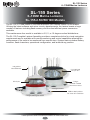
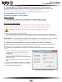
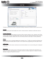
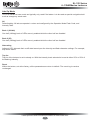
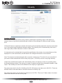
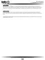
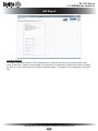
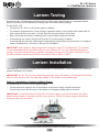
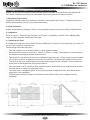
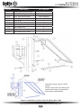
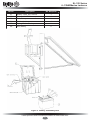
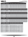
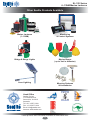
SL-155 Series
SL-155-2.5D/5D/10D Models
Marine Lanterns
Installation & Service Manual
Version 1.2
Version No.
1.0
1.1
1.2
Description
Manual Launch
Manual Update
Spec Update
Date
June 2014
August 2014
March 2015
Approved
Y. Chambers
Y. Chambers
J. Dore
SL-155 Series
6–13NM Marine Lanterns
Table of Contents
Introduction........................................................................................................ Page 4
Operating Principle........................................................................................... Page 4
Technology......................................................................................................... Page 4
SL-155 Series..................................................................................................... Page 5
Product Components ....................................................................................... Page 8
Programming the Lantern: PC Configuration Tool........................................ Page 9
Info Tab....................................................................................................... Page 13
Operation mode Tab.................................................................................. Page 14
Flash Code................................................................................................. Page 16
Intensity...................................................................................................... Page 17
Sensors....................................................................................................... Page 18
AIS Report.................................................................................................. Page 20
Programming the Lantern: IR Programmer.................................................. Page 21
Sealite IR Controller / Universal Remote Compatibility......................... Page 21
IR Programmer Functions......................................................................... Page 22
Test Mode / Configure............................................................................ Page 22
Normal Operation................................................................................... Page 22
Read....................................................................................................... Page 22
Flash Code............................................................................................. Page 23
Flash Code Numbers............................................................................. Page 23
Intensity.................................................................................................. Page 23
Battery Status......................................................................................... Page 24
Lux......................................................................................................... Page 24
Error / Acknowledge Indication............................................................... Page 25
Configuration Settings............................................................................ Page 25
Operational Mode (Advanced Users)..................................................... Page 26
Lantern Testing................................................................................................ Page 27
Lantern Installation......................................................................................... Page 27
Optional GPS Synchronisation...................................................................... Page 33
Optional GSM Monitoring & Control System................................................ Page 34
Maintenance & Servicing................................................................................ Page 35
Trouble Shooting............................................................................................. Page 36
Appendix: Flash Codes................................................................................... Page 37
Sealite LED Light Warranty............................................................................ Page 42
Latest products and information available at www.sealite.com
3
SL-155 Series
6–13NM Marine Lanterns
Introduction
Congratulations! By choosing to purchase a Sealite lantern you have become the owner of
one of the most advanced LED marine lanterns in the world.
Sealite Pty Ltd has been manufacturing lanterns for over 25 years, and particular care has been taken to
ensure your lantern gives years of service.
As a commitment to producing the highest quality products for our customers, Sealite has been independently
certified as complying with the requirements of ISO9001:2008 quality management system. Sealite lanterns
comply with requirements of the US Coast Guard in 33 CFR part 66 for Private Aids To Navigation.
By taking a few moments to browse through this booklet, you will become familiar with the versatility of your
lantern, and be able to maximise its operating function.
Operating Principle
A microprocessor drives an array of ultra bright LED’s through a DC/DC converter, which enables the LED’s to
operate within the manufacturer’s specifications.
On darkness, the microprocessor will initiate a program check and after approximately 1 minute begin flashing
to the set Flash Character.
The flasher unit has a low current requirement to optimise its use with external battery power supply systems.
Technology
Sealite is the world’s fastest growing manufacturer of marine aids to navigation. We
employ leading mechanical, optical, hardware & software engineers to create innovative
products to service the needs of our customers worldwide, and offer the widest range of
solar-powered LED lanterns in the marketplace.
Electronics
Sealite employs leading in-house electronic engineers in the design and development of software and related
circuitry. All individual electronic components are sourced directly by Sealite procurement staff ensuring that
only the highest quality components are used in our products.
LED Technology
All marine lanterns use the latest advancements in LED (Light Emitting Diode) technology as a light source.
The major advantage of LED’s over traditional light sources is well established in that they typically have an
operational life in excess of 100,000 hours, resulting in substantial savings to maintenance and servicing
costs.
Precision Construction
Commitment to investing in the design and construction of injection-moulded parts including optic lenses, light
bases and a range of other components ensures that all Sealite products are of a consistent & superior quality.
Optical Performance
Sealite manufactures a range of marine LED lenses moulded from multi-cavity dies. The company has
superior in-house lens manufacturing capabilities to support outstanding optical performance.
Award-winning, Patented Technology
Several United States and Australian patent registrations are held on Sealite’s range of innovative designs,
with other regional patents pending in Canada, United Kingdom and Europe.
Latest products and information available at www.sealite.com
4
SL-155 Series
6–13NM Marine Lanterns
SL-155 Series
6–13NM Marine Lanterns
SL-155-2.5D/5D/10D Models
The SL-155, 6-13NM lantern is the most advanced LED marine lantern on the market.
Utilising the latest software and micro circuitry developments, the lantern boasts a huge
number of features including flash-memory and the most efficient power conversion
available.
This maintenance-free model is available in 2.5, 5, or 10 degree vertical distributions.
The SL-155 Complete Lantern Assembly provides a complete solution for visual navigation
requirements and is available with remote monitoring and control capabilities allowing the
performance of the units to be monitored from remote sites. System status includes battery
condition, flash characters, operational configuration, and lantern/buoy position.
Integrated
bird deterrent
UV-stabilised
acrylic lens
LED Optic
7-stage
powder coated
aluminium base
2.5 degree model
200mm bolt pattern
for ease of installation
5 degree/10 degree model
Latest products and information available at www.sealite.com
5
SL-155 Series
6–13NM Marine Lanterns
SL-155-5D & SL-155-10D Models
224
171
30°
231
95.3
104
151
217
217
0
20 s
D
PC lace
6P
D
PC
0
20
16 X 15 Slots
6 Places
230
230
SL-155-2.5D Model
104
104
151
151
30°
231
217
231
224
D
PC
Latest products and information available at www.sealite.com
6
0
PCD 200
6 Places
20
16 X 15 Slots
6 Places
230
230
Light Characteristics
Light Source
Available Colours
Maximum Luminous Intensity (cd)†
5o & 10o Models
2.5o Model
SL-155-5D & SL-155-10D
SL-155-2.5D
High efficiency LEDs
Red, Green, White, Yellow
2.5 degree model: Red - 4593 Green - 4413
White - 7900 Yellow - 4259
Intensity Adjustments
LED Life Expectancy (hours)
High efficiency LEDs
Red, Green, White, Yellow
5 degree model: Red - 2660 Green - 2318
White - 3829 Yellow - 2185
10 degree model: Red - 1810 Green - 1881
White - 3078 Yellow - 1632
AT @ 0.74: 6–13 AT @ 0.85: 7.8–19.2
0o - 360o
5o or 10o
Up to 310 including 256 IALA recommended,
& 1 custom
User adjustable
>100,000
Typical Power (W)
Circuit Protection
Nominal Voltage (VDC)
Temperature Range
Variable up to 18
Polarity protected
12–24
-40 to 80°C
Variable up to 18
Polarity protected
12–24
-40 to 80°C
Body Material
Lens Material
Lens Diameter (mm/inches)
Lens Design
Mounting
Height (mm/inches)
Width (mm/inches)
Mass (kg/lbs)
Product Life Expectancy
7-stage powder-coated aluminium
UV-stabilised acrylic
171 / 6¾
Multiple LED optic
3 & 4 hole 200mm bolt pattern
217 / 8½
230 / 9
5 / 11
Up to 12 years
7-stage powder-coated aluminium
UV-stabilised acrylic
224 / 8¾
Multiple LED optic
3 & 4 hole 200mm bolt pattern
231 / 9⅛
230 / 9
5.5 / 12¼
Up to 12 years
Shock
MIL-STD-202G Test Condition H, Method 213B
30G vertical and 35G horizontal shock
MIL-STD-202G, Test Condition B, Method 204D
5G in all axes
MIL-STD-202G, Method 104A
Rated to withstand continuous exposure to
salt water and spray
Rated to withstand 22kg/m2
Rated to withstand 140knots
Rated to withstand 25mm diameter ice ball
impact at 20m/s
0 – 100%, condensing
at 45° from vertical
FCC Part 15 Rules & ICES-003.
EN61000-6-1: 2007 (IEC61000-6-1:2005) Part
6-1 Immunity.
EN61000-6-3: 2007 (IEC61000-6-3: 2006)
Electromagnetic compatibility (EMC) - Part
6-3 Emission.
IEC61000-4-2: 2008 Ed 2 Part 4-2 Electrostatic
discharge immunity test Level 4.
IEC61000-4-3: 2010 Ed 3.2 Part 4-3. Radiated,
radio-frequency, electromagnetic field
immunity.
IEC61000-4-6: 2008 Ed3. , Electromagnetic
compatibility (EMC) - Part 4-6 Immunity.
Signal colours compliant to IALA E-200-1
ISO9001:2008
IP68
SEALITE® is a registered trademark of Sealite
Pty Ltd
3 years
• GPS Synchronisation
• AIS Type 1 or Type 3
• GSM Monitoring & Control System
• RS232/422/485 Port
• General purpose inputs (2) & outputs (2)
• Variety of solar/battery configurations
• Serial programming cable
• Hard-wire Synchronisation
Visible Range (NM)
Horizontal Output (degrees)
Vertical Divergence (degrees)
Available Flash Characteristics
Electrical Characteristics
Physical Characteristics
Environmental Standards
Vibration
Immersion
Salt Fog
Ice Loading
Wind Exposure
Hail Impact
Humidity
Driving Rain
Certifications
CE & Electrical
IALA
Quality Assurance
Waterproof
Intellectual Property
Trademarks
Warranty *
Options Available
AT @ 0.74: 6–13 AT @ 0.85: 7.8–19.2
0o - 360o
2.5o
Up to 310 including 256 IALA recommended,
& 1 custom
User adjustable
>100,000
• Specifications subject to change or variation without notice
* Subject to standard terms and conditions
† Intensity setting subject to solar availability
SPECIFICATIONS•*
SL-155 Series
6–13NM Marine Lanterns
Product Components
The following components come standard with each lantern:•
SL-155 lantern
•
IR Programmer
•
Installation & service manual
These components are securely packaged within foam in a carton, and shipped to you.
PLEASE NOTE: The programming cable provided is suitable for use with PC’s. If you require
connection to your notebook/laptop, a Serial Port to USB cable may need to be purchased.
Please check that ALL of these components are included with your order, and
contact your Sealite representative as soon as possible if anything is missing.
Latest products and information available at www.sealite.com
8
SL-155 Series
6–13NM Marine Lanterns
Programming the Lantern
PC Configuration Tool
The lantern is pre-programmed to the customer’s specific requirements for convenience (eg. flash,
intensity setting etc).
The SL-155 Series are extremely intelligent lanterns with a number of features which can be
programmed directly via a user-friendly computer program (as supplied on USB drive with every
lantern).
To change/update the settings of your lantern, please read the following instructions.
1. Run the Programming Software
The programming software may be run directly from the USB drive provided, or you may copy the
software to your computer hard-drive for future use.
Running the Programming Software from the USB Drive
•
Connect the USB drive to your computer
•
Navigate to the USB drive folder & double-click the file called “LanternConfig.exe”. A new window
will appear displaying the PC Configuration Tool.
Saving the Programming Software to Computer Hard-Drive
•
Connect the USB drive to your computer
•
Navigate to the USB drive folder
•
Copy the file called “LanternConfig.exe” and the “.dll” files
•
Navigate to the hard-drive location where you would like to save this program, and then rightmouse-click and select “paste”. A copy of the programming software will now be saved to your
computer hard-drive (to add the programmer to your computer desktop for ease of future access,
right-mouse-click and select “Send to desktop”)
•
Double-click the file called “LanternConfig.exe”. A new window will appear displaying the PC
Configuration Tool
PLEASE NOTE: other documents have been saved on the USB drive for your information &
convenience including the latest product specifications sheet and an electronic version of the
installation and service manual. You may wish to view these documents to read more about the
innovative features and benefits of the SL-155 Series of lanterns.
IMPORTANT: the Sealite PC Configuration Tool is designed for Windows Platforms only.
Latest products and information available at www.sealite.com
9
SL-155 Series
6–13NM Marine Lanterns
Image 1. Sealite PC Configuration Tool
Latest products and information available at www.sealite.com
10
SL-155 Series
6–13NM Marine Lanterns
2. Connect the SL-155 Series Lantern to a Power Source & the Computer
Now that the programming software has been run, you will need to connect the lantern to your
computer & power supply so that it can receive programming commands.
Once connection is made, the software automatically determines the colour and
preprogrammed settings of the lantern.
Connecting the Lantern to a Power Source
Option 1: Battery
•
Connect the blue negative wire of the lantern to the battery negative terminal
•
Connect the brown positive wire of the lantern to the battery positive terminal
Option 2: 12V Power Supply
•
Connect the blue negative wire of the lantern to the power supply negative termainal
•
Connect the brown positive wire of the lantern to the power supply positive terminal
CAUTION: to avoid personal injury do not position the lantern at eye level.
Connecting the Lantern to the Computer
•
Plug the Bulgin connector end of the the programming cable into the lantern PC Programming
Port, and the serial port end of the cable into your computer serial/communication port (RS232-E)
PLEASE NOTE: The programming cable provided is suitable for use with desktop PC’s. If you require
connection to your notebook/laptop, a Serial Port to USB cable may need to be purchased.
3. Establish the Programmer-to-Lantern Computer Connection (COM Port)
Now that the lantern is connected to the computer and the Sealite PC Configuration software has
been run, the user must create the programmer-to-lantern connection.
The COM Port is the hardware port which the computer accesses when communicating with the
lantern.
•
Click the “COM Setup” at the top left of the PC
Configuration Tool to open the “Serial Port”
dialogue box
•
In the “Serial Port” dialogue box select the
appropriate COM Port from the drop down field
for “Port Name”
•
Check the “Open Port” check box to open the
port
• Click the “OK” button to initiate the connection
The Sealite PC Configuration Tool will then attempt
to connect/interrogate the lantern.
Image 2. Serial Port dialogue box
Latest products and information available at www.sealite.com
11
SL-155 Series
6–13NM Marine Lanterns
Correct Connection Established
If the connection is established data about the lantern configuration will appear on the “Info” tab under
the headings “Version” & “Lantern Summary” (eg. Lantern Colour, Flash Code, Intensity etc).
Image 3. Sealite Configuration Tool “Info” tab – showing COM Port connection established,
Version & Lantern Summary information
Connection NOT Established
If the connection is not available, the Sealite PC Configuration Tool will not display any lantern
specific information under the headings “Version” & “Lantern Summary”. If this error occurs, please
check the following:
•
Reconnect the lantern to the computer
•
Check that the lantern power supply has sufficient charge (eg. battery is charged), and then
reconnect it to the lantern
•
Re-run the Sealite PC Configuration Tool and follow the information in step 3. The connection
should now become established.
The Sealite lantern is now ready to be programmed to your specific requirements.
Latest products and information available at www.sealite.com
12
SL-155 Series
6–13NM Marine Lanterns
Info Tab
Provides a summary of the lantern configuration settings, hardware and software versions, and event log.
Version
Is an information panel that identifies the Lantern’s internal electronic hardware and firmware versions.
Lantern Summary
Is an information panel that displays a summary of the key lantern settings: colour, operation mode, Peak
Intensity setting, Advance Operational Mode, Flash Code, Flash Sync offset and Intensity setting. Refer to
the Information, Operation Mode Flash Code, and Intensity Tabs for a description of these parameters.
Name
A user defined name, comprising alphanumeric characters (and -, $, #,@) can be typed into dialogue box
and by pressing and stored within the lantern’s non-volatile memory by pressing the ‘Write Name’ button.
LED Colour
A generic picture of the lantern model and colour that the software tool is communicating with is displayed
in this panel.
Event Log
Displays the number of alarm event recorded by the lantern firmware. Possible alarms (flat battery, low
battery, LED failure, high temperature). All alarm events are recorded irrespective of whether the lantern
has been configured to respond to an alarm.
Latest products and information available at www.sealite.com
13
SL-155 Series
6–13NM Marine Lanterns
Operation mode Tab
Defines the lanterns mode of operation of which there are four possibilities:
Operational Mode
Standby
The lantern is configured in a minimum current state in which the LEDs are always off and the internal
GPS (if installed) is disabled.
Always On
The daylight sensor is disabled and the lantern operates according to the set flash character and
intensity levels.
Dusk till Dawn
The daylight sensor is monitored and the lantern will only operate at night time.
Time after dusk
Lantern only turns on after dusk and for a defined period of time (hours)
Latest products and information available at www.sealite.com
14
SL-155 Series
6–13NM Marine Lanterns
Adv Op Mode
This is an advanced user mode and typically only used if the lantern is to be used as special navigational aid
such as emergency wreck mark.
All
Default setting. All leds are operate in unison and configured by the Operation Mode Flash Code, and
Intensity Tabs.
Bank 1 (Visible)
One half (180deg) bank of LEDs are only enabled whilst the other half are disabled.
Bank 2 (IR)
One half (180deg) bank of LEDs are only enabled whilst the other half are disabled.
Alternating
Adjacent LED, alternate their on/off state based upon the intensity and flash character settings. For example,
ship wreck marks.
Top tier
Top tier of the lanterns is set to steady on. With the intensity levels selected to be set to either 25% or 50% of
the flashing intensity.
Reset
Within the lantern, set at the factory, all the parameters are return to default. The event log is remains
unchanged.
Latest products and information available at www.sealite.com
15
SL-155 Series
6–13NM Marine Lanterns
Flash Code
Marine Characteristic Selection
The flash character is defined by first selecting the Mariner code, then the Flash code name and finally
timing.
Sealite Code Selection
This is an alternative method to define the lantern flash code by using either the Sealite IR remote
control numerical figure or if known the Sealite rotary switch flash character. Refer to the IR remote
control section for valid flash characters.
Sync Offset
This panel is used to set a fixed delay to the commencement of the flash character. The inbuilt
GPS receiver and advanced software of the Sealite synchronised lanterns allow for the adoption of
SeaFlare™ channel marking – a unique system that cascades the flash synchronisation of channel
lanterns in a uni- or bi-directional flash pattern. By default this figure is set to zero.
Manual Entry Custom Flash Character
In this panel one, custom flash characteristics can be defined with up to 10 individual on/off times.
Latest products and information available at www.sealite.com
16
SL-155 Series
6–13NM Marine Lanterns
Intensity
Lantern intensity
The lantern intensity level can be set by either by defining the operating range of the lantern (in
Nautical miles) or by entering a desired peak candela or a percentage of maximum peak intensity
level.
If Schmidt Clausen is applied is selected, the lantern will automatically adjust the intensity level based
up on the entered range and flash character setting. The intensity level is automatically each time a
new range (NM) or flash character is written to the lantern.
If a intensity level is selected that is beyond the specification of the lantern, the entered figure will be
displayed in in red coloured text, and the lantern will configure the lantern to its maximum.
Note: The lanterns has been designed with a dynamic intensity limit. This limit will come into effect if
you select a flash characteristic with a heavy duty cycle (> 28.125%) and set a very high intensity.
Under these conditions the lantern will automatically reduce its intensity so that it is operating within
the thermal design window. Thus giving you years of operation without any noticeable degrade in light
output. This intensity limit will not be reached for the majority of applications.
The peak power limit for the SL-155-5D and Sl-155-10D lanterns has been set to 28.125%. There are
69 flash codes in the base table of 256 that will have an intensity cap.
The peak power limit for the SL155-2 has been set to 34.375%. There are 51 flash codes in the base
table of 256 that will have an intensity cap.
Latest products and information available at www.sealite.com
17
SL-155 Series
6–13NM Marine Lanterns
Sensors
Battery sensors
The SL-155 series of lantern continuously monitors its input voltage comprising three used finable
thresholds.
• Voltages greater than “OK” level the lantern reports via IR Remote control requests or the GSM that
the input voltage is satisfactory.
• Voltages below “low” the lantern can be configured to operate the internal alarm relay and /or
reduce the intensity level by 25% as measure to extend the operation of the lantern until it reaches
the “Fail” voltage.
• At “Fail” the lantern shuts down entirely, and turns of the GPS and the mains LEDs. The lantern will
only commence operation once the input voltage has exceeds the “OK” voltage level.
The three thresholds, Flat, Low and OK are user definable.
Temperature
The SL-155 utilises two temperature sensors. One on contact with the LED heat sink and second that
monitors the internal temperature within the lantern.
Each sensor has two user configurable boundaries. At the “low” boundary temperature point, the
lantern intensity is reduced by 25% to help reduce the heating of the housing. Reaching this point
down not trigger the alarm reply. The second boundary is “high”, where at which point, the lantern
turns off and triggers the alarm reply.
Latest products and information available at www.sealite.com
18
SL-155 Series
6–13NM Marine Lanterns
LED Sensor
Built into the SL-155 lantern, is a closed loop monitoring system for each LED within the lantern. In
the event of a single LED failure is detected, the lantern can be configured to trigger the internal alarm
relay which in turn can be connected eternally to trigger other devices such a redundant light source.
Light Sensor
The SL-155 lantern has its own internal light sensor and whose day/night thresholds are defined in
LUX. These levels can be customised by entering in separate dusk and dawn values as a measure of
LUX.
If optioned, an external light sensor such as Light dependant resistor or photodiode can be electrically
connected to the SL-155.
Latest products and information available at www.sealite.com
19
SL-155 Series
6–13NM Marine Lanterns
AIS Report
Lantern Status
This panel display the Lantern’s AIS message that is outputted via the serial communications port
every 10seconds. Typically this message is processed by an externally installed AIS module, however
by itself as is quick summary of the lantern operating status. This detail is also displayed on the INFO
tab.
Latest products and information available at www.sealite.com
20
SL-155 Series
6–13NM Marine Lanterns
IR Programmer
The IR programmer is used to communicate with Sealite lighting products
that have an IR sensor fitted. The remote control is used for the following
functions:
Test / Configure
T/C
• Flash Code: read the current flash code, configure a new flash code.
• Lamp Intensity: read the current lamp intensity, configure a new intensity
level.
1
2
3
• Ambient Light Thresholds: read the current light thresholds, configure new
ambient light thresholds.
4
5
6
7
8
• Perform a battery health check.
On receiving a valid key signal from the IR Programmer, the light will flash
once. The user should wait until the light responds to each keypress before
pressing another key. If there is no response to the keypress after 3 seconds,
it has not been detected by the light and the key can be pressed again.
If an invalid key is detected, the light will flash quickly 5 times. In this case, the
command will have to be restarted.
Read
9
Lux
R
0
L
Flash Code
Intensity
Battery Status
FC
I
B
Sealite IR Programmer / Universal Remote Compatibility
If you lose your Sealite IR Programmer, the following Universal Remote Controller has been tested for
compatibility: RCA Type RCR312WR programmed for Phillips TV Type Code 10054
Sealite Key
Universal
Remote Key
T
Power
1
1
2
2
3
3
4
4
5
5
6
6
7
7
8
8
9
9
0
0
R
Channel+
L
Mute
FC
Volume+
I
Volume-
B
ChannelLatest products and information available at www.sealite.com
21
SL-155 Series
6–13NM Marine Lanterns
IR Programmer Functions
Test Mode / Configure
T/C
1
4
7
R
FC
1
4
7
1
R
4
FC
7
R
FC
Pressing the T/C button for upto 5 seconds places the light in Test Mode. The light will flash once in
response to the T/C button being pressed and then turn off.
2
3
5
6
T/C
9
T/C
1
2
3
Normal T/C
Operation
L
0
The light will return to normal operation once it has not detected a valid key press for 30 seconds. The
light
1 will flash
2
4 once 3
5to indicate
6 it is returning to normal operation.
1I T/C
2B 3
T/C
Read
4
5
7 Read 6
8
9
Pressing
1
2value.
3followed by one of the configuration keys shall cause the light to flash the
4 the
5
6
configured
2 T/C
3
Example
Key
R Sequences:
L
0
7
8
9
4
5
6
7
8
9
1
2
3
5 T/C
6
The light flashes the ‘IR Remote’ number belonging to the currently set Flash
T/C
R
LI Code.
0 T/C
FC
B Refer to the Flash Code tables to match the ‘IR Remote’ flash number
R
0
7
8
9L to the Flash Code.
4
5
6
8
9
1
2
3
2
3
1I
2
FC
B The3light flashes the current intensity setting: 1 flash for 25%, 2 for 50%, 3 for
T/C
R
0
I
BL 75% and 4 for 100%.
FC
7
8
9
L
0
5
4
6
5
6
4
5
6
1I
2
FC
B The3light flashes the current battery status.
RI
L
0 T/C
B
8
7
9
8
9
7
8
9
4
5
6
The3light flashes the sunset level in Lux, followed by a 2 second gap, followed
1I
2
FC
B
R
L T/C
L
0
0
R
L sunrise level. Levels are in the range of 1 to 5.
0 by the
7
8
9
4
5
6
1
2
3
I
BI
FC
B
FC
I
B
R
L
0
7
8
9
4
5
6
FC
I
B
R
0
7
8
9L
8
FC
R
0I
BL
FC
I
B
Latest products and information available at www.sealite.com
22
4
5
6
17
2
8
3
9
4R
50
6L
7
FC
8I
9B
Flash Code
SL-155 Series
6–13NM Marine Lanterns
This key sets the flash code on the light.
R
0
L
T/C
FC
1I
2B
3
T/C
T/C
4
5
1
6
2
3
Example Key sequence:
This sets the flash code to value 123. The light responds by flashing the flash code value.
1
Flash
2 Code
3 Numbers
4
The flash for number 0 is one long flash.
1
7
14
R
4
7
FC
7
R
7
8
4
9
5
6
R6
0
7
L
8
9
T/C
2
8
3
9
FC
I
R
B
0
L
2
5
0
3
6L
FC
I
B
5
8I
6
9B
The lamp flashes numbers as follows: Hundreds, Tens, Ones. A value of 125 will be flashed as: 1 flash,
followed by a delay, 2 flashes, followed by a delay, 5 flashes.
T/C
5
For example if the current Flash Code is set to 51 via the AB switches, the lamp will flash number 081.
For a flash code set to 01, the lamp will flash 001.
Intensity
This function sets the light intensity and is automatically calculated by user selecting the required
operational range of the lantern.
8
0
9L
R
FC
0IL
xL
B
FC
IL
B1xL T/C
2x
4
T/C
T/C
51
writes the range in nautical miles (0–9) where x represents the range
T/C
T/C
3
62
writes the range in nautical miles (0–32) where x represents the range
3
A range value from 6 to 13NM is valid however the maximum allowable range is dependent on the
lantern’s vertical divergence, LED colour and flash character.
Using the selected operational range and current flash character, the lantern uses the Schmidt-Clausen
Method, as described in IALA E200-4 to determine the peak intensity.
7
84
95
6
If the flash character is changed, the peak intensity is automatically adjusted.
R
07
L8
9
FC
RI
B0
L
FC
I
B
Latest products and information available at www.sealite.com
23
T/C
8
1
0
4
7I
R
FC
9
2
SL-155 Series
6–13NM Marine Lanterns
T/C
3
L
Battery
Status
1
2
5
6
3
B
4
8
5
9
6
7
0
8L
9
RI
0
B
L
T/C
FC
1I
2B
3
4
5
6
7
x
R
8
T/C
0
9
I
T/C
B
This function reads the battery status. The response from the light is High Voltage: 4 flashes,
Good Voltage: 3 flashes, Low Voltage 2 flashes, Cutoff Voltage or below: 1 flash.
Example Key sequence:
Lux
L
L
This key sets the ambient light threshold levels.
The format is
L
FC
x
Where ‘x’ is the desired setting from the table below.
There are 5 programmable lux levels which are set together for the sunset and sunrise transitions.
Sunset
(Dusk)
Level
Sunrise
(Dawn)
1
64
100
2*
100
150
3
150
240
4
240
370
5
370
600
* Default / Factory Preset
Example key sequence:
L
1
T/C
Assume the current Lux settings are at the factory preset values of 2.
This sets the ambient light level to be lower than the default 100 lux. The light will turn on when its
surroundings are darker.
The light responds by acknowledgement with a long flash.
Latest products and information available at www.sealite.com
24
1
2
3
4
5
6
7
R
FC
SL-155 Series
6–13NM Marine Lanterns
Error
Indication
T/C
8 / Acknowledge
9
If the key sequence is invalid, or an out of bounds value is attempted to be set, the light flashes 5
times for 1 second. (The command then needs to be sent from the start.)
1
0
2L
3
4I
5B
6
T/C
Example key sequence: (Set the intensity level to 5 – undefined.)
The light flashes 5 times for 1 second.
7
81
92
3
R
04
L
5
6
When a key sequence has been entered successfully the light will respond acknowledgement with a
long 1 second flash.
FC
B8
7I Settings
9
Configuration
The intensity and flash codes can be changed using the switches on the lamp circuit board or with the
IR Remote Control. The lamp intensity and flash code settings are set to the last detected change,
carried out with the IR Remote Control or by changing the switch positions.
R
0
L
Example #1: If the intensity is set at 100% with the intensity switches, and is then set to 50% using
the IR Remote Control, the intensity setting will change to 50%. If the intensity is then set to 75% using
the switches, the new intensity value will be 75%.
FC
I
B
In order to change intensity settings using the IR Remoter Control, the lamp must be powered.
The lamp can detect a change in switch settings if they are changed while the light is powered down.
Example #2: The flash code is set according to the switch settings: A=5, B = 1. The operator changes
the flash code to 65 (A=4, B=1) using the IR Remote Control. The new flash code is now configured to
A=4, B=1. The lamp is powered down and the operator changes the flash code switches to A=3, B=1
and powers on the light. The new flash code is now A=3, B=1. If the flash code is read from the light
using the IR Remote Control, the lamp will flash 49 which is the corresponding number for switches
A=3, B=1.
Use the IR Remote Control to read the current lamp intensity setting and flash code.
Latest products and information available at www.sealite.com
25
SL-155 Series
6–13NM Marine Lanterns
Operational Mode (Advanced users)
The lantern has three modes of operation: Always on, Standby Mode and Dusk-to-Dawn mode. These
modes can be selected either via the IR remote control or via the GSM module (if fitted).
In Always On mode, the daylight sensor is disabled and the lantern will remain ON.
In Standby mode, the lantern is turned off and the daylight sensor is disabled. This mode does not
affect the operation of the GSM module.
In Dusk-to-Dawn, the daylight sensor is enabled.
L
B
1
T/C
Always on mode
L
B
2
T/C
Standby mode
L
B
3
T/C
Dusk-to-Dawn mode
Latest products and information available at www.sealite.com
26
SL-155 Series
6–13NM Marine Lanterns
Lantern Testing
Now that the SL-155 has been programmed to suit the project requirements, it’s important that the
lantern is tested prior to installation, including flash code and intensity settings.
To test the SL-155:
•
Connect the SL-155 to a 12V power supply or battery
•
For lanterns programmed to “Dusk to Dawn” operation setting, cover lantern with a dark cloth or
jack in darkness for more than 1 minute. After this time the lantern will activate
•
Next, check that the lantern is flashing to the required flash code and intensity
•
If the settings are correct, disconnect from the 12V power supply or battery
•
If the settings are incorrect, following the Programming Instructions of this manual to re-configure
lantern characteristics, and then re-test prior to installation
IMPORTANT: when lantern is being programmed using the Sealite PC Configuration Tool software,
it is recommended that the operation setting is set to “Always On” for ease of testing/viewing new
settings. Once the programming is complete, remember to change the operation mode back to your
specific installation requirement (Sealite recommend “Dusk to Dawn” mode).
Lantern Installation
The Sealite SL-155 may be installed with connection to mains power, or as a complete solar powered
system (available from Sealite).
IMPORTANT: the SL-155 must be installed appropriately where the lantern is not blocked by buildings,
trees or other shadows that may affect the visibility of the lantern or the ambient light.
Option 1: Installation of Lantern to Mains Power
To connect the SL-155 to a 12VDC power supply:
•
Connect the blue negavite wire of the lantern to the power supply negative termainal
•
Connect the brown positive wire of the lantern to the power supply positive terminal
IMPORTANT: it is important that a 15Amp AC-DC power supply is connected between the mains
power and the lantern to maximise the life of your product. The AC-DC power supply should be no
more that 20m from the lantern.
2.5 degree model
5 degree/10 degree model
Latest products and information available at www.sealite.com
27
SL-155 Series
6–13NM Marine Lanterns
Option 2: Installation of Lantern to Solar Powered System
Sealite has an optional complete solar powered system available to purchase with the standard SL155 lantern. Detailed instructions for installation of the solar system are listed as follows.
1. Unpacking Instructions
Unpack all hardware and verify container contents in accordance with Figure 2. Please contact your
Sealite representative if there is any hardware missing.
2. Initial Inspection
Inspect all hardware for damage. If there is any damage, please contact your Sealite representative.
3. Installation
Refer to Figure 1 “Panel & Cage Footprint” and Figure 2 “Installation of Solar Panel & Battery Box
Cage” during installation of the panel and cage.
3.1 Installing the Post
A suitable mounting point for the Solar Panel and Battery Box Cage is to be provided by the client. It is
usual to use a purpose installed post.
The following should be observed:•
The post should be of a durable timber, or other durable material
•
Recommended minimum post size is 150mm x 150mm, or larger if the battery box cage needs to
be installed immediately beneath the solar panel
•
The length of post required is the sum of exposed length (normally 1.25m) plus the required depth
into the ground which is dependent on local soil conditions (recommended depth 850 minimum)
•
The faces of the post must be aligned with the cardinal points of the compass. This will allow the
Solar panel to be aligned with the equator and sun
•
The post should not be more than 20m from the lantern, and should not be located so as to place
the solar panel in shade for a significant time
•
The solar panel is tempered glass, so the post should be located away from any objects which
might fall on the installation
•
The post and equipment footprint should be at least 300mm clear of any shading under all
conditions
Latest products and information available at www.sealite.com
28
SL-155 Series
6–13NM Marine Lanterns
Ref No.
Description
No. Required
2.1
140W Solar Panel & Frame
2.2
Battery Box Cage
1
2.3
Post, 150x150 minimum
2.4
Steel Support
2.5
Steel Brace
1
2.6
Screw, 12mm x 75
12
2.7
Washer, 12mm
12
2.8
Bolt, 10mm x 25
4
2.9
Washer, 10mm
4
2.10
Self Locking Nut, 10mm
4
1
Client Supplied
1
Alternative setup, using 2 x 85W
panels.
Lantern duty cycle and intensity will
determine the size and quantity of
solar panels and batteries.
Figure 2. Installation of Solar Panel & Battery Box Cage
Latest products and information available at www.sealite.com
29
SL-155 Series
6–13NM Marine Lanterns
3.2 Installing the Solar Panel & Battery Box Cage
The battery box cage (Ref 2.2) and the steel support bracket (Ref 2.4) are attached to the post (Ref
2.3) using coach screws and washers (Ref 2.6, 2.7).
a. Drill the post for the steel support bracket (6 places) and install using supplied screws
IMPORTANT: the Solar Panel must face the equator. Locate the solar panel support bracket
accordingly.
b. Drill the post for the battery box cage (6 places) on the opposite side to the solar panel and install
using supplied screws
c. Install the solar panel and frame (Ref 2.1) and the brace (Ref 2.5) to the steel support bracket
using bolts (Ref 2.8), washers (Ref 2.9) and nuts (Ref 2.10)
3.3 Installing the Battery Box
Refer to Figure 3 “Battery and Battery Box” during installation of the battery and battery box.
a. Open the battery box cage door and place the battery case (Ref 3.1) into the cage with the hinge
of the case adjacent to the hinge of the cage
b. Open the battery case and lower the battery into the case ensuring the battery terminals are
upright
c. Insert one bolt (Ref 3.3) with a washer (Ref 3.4) under the head through each of the battery
terminals
d. Place the red eye connector over the tail of the bolt protruding through the red battery terminal
e. Fit a washer (Ref 3.4), spring washer (Ref 3.5) and nut (Ref 3.6) on the terminal bolt. Tighten
f. Place the blue eye connector over the tail of the bolt protruding through the black battery terminal.
Fit a washer (Ref 3.4), spring washer (Ref 3.5) and nut (Ref 3.6) on the terminal bolt. Tighten
g. Insert the end of the cable from the solar panel through one of the cable glands in the back of the
battery case. Join bullet connectors, red to red and blue to blue
•
Test the lantern. Cover the lantern completely to resemble night time. Allow 60 seconds for the
lantern to activate
•
Uncover the lantern and it will turn off after 60 seconds
Latest products and information available at www.sealite.com
30
SL-155 Series
6–13NM Marine Lanterns
Ref No.
Description
No. Required
3.1
Battery Case, SPC353534
1
3.2
Battery, 12V 70AH or equivalent
1
3.3
Bolt, battery
2
3.4
Washer, battery
4
3.5
Spring Washer, battery
2
3.6
Nut, battery
2
Figure 3. Battery and Battery Box
Latest products and information available at www.sealite.com
31
SL-155 Series
6–13NM Marine Lanterns
3.4 Connecting the Lantern
To connect the SL-155 to the solar powered system:
•
Connect the blue negative wire of the lantern to the battery negative termainal
•
Connect the brown positive wire of the lantern to the battery positive terminal
The lantern must to be connected to a 12VDC power supply.
Please ensure the solar panel array has been installed appropriately. To maximise solar collection,
the solar panel array should be installed facing the equator and in a location that ensures it will not be
shaded by buildings, trees or other structures. Solar panels will significantly reduce in efficiency if
a small shadow is positioned over the solar panel.
IMPORTANT: it is important to work with the team at Sealite when determining the quantity and size
of both batteries and solar panels for this lantern. Duty cycle, intensity and local solar conditions are
important factors to take into consideration when building a solar powered battery supply.
Sealite solar marine lanterns will give years of trouble free service if installed correctly initially.
•
Please ensure all connections are tight
•
Please ensure that solar panels are always clean and free from bird droppings and shade and that
the solar array it pointed toward the sun to maximise solar collection
•
Please ensure that battery box covers are latched properly and that cages are secured
appropriately, to prevent theft and vandalism
Please contact your Sealite representative if you have any questions regarding the installation
and service of the lantern.
Latest products and information available at www.sealite.com
32
SL-155 Series
6–13NM Marine Lanterns
Optional GPS Synchronisation
The lanterns can be fitted with a GPS module, and provide the user with the ability to install
independently operating lanterns that all flash in synchronisation.
No additional power supplies, aerials or control systems are required, and with its microprocessorbased system, the GPS option is specifically designed to provide maximum reliability and performance
over a wide range of environmental conditions.
Operating Principle
Each light operates independently and requires no operator intervention. A minimum of 4 satellites
need to be in view for the built-in GPS receiver to collect time data. At dusk, the light sensor will turn
the light on. If time data is available the light will come on synchronised to every other light with the
same selected flash code.
Synchronisation is achieved using an internal algorithm based on the highly accurate time base and
time data received from the satellites. The satellite data is provided from a number of earth stations
using atomic clocks as the time base. Continuous self-checking ensures that the light will continue to
run in synchronisation.
Light Activation
At power-up the microprocessor checks that the internal GPS module is programmed correctly and is
able to provide valid time base and time data.
Once outside with a clear view of the sky, valid data should become available within 20 minutes.
Daylight Operation
During daylight hours the microprocessor is in idle mode to reduce power consumption. Time data
continues to be updated once per second. The microprocessor will automatically exit the idle mode as
soon as dark conditions are detected.
Dark Operation
When dark conditions are detected the light:
•
Checks for valid time data and is turned on after a delay based on the current time and the length
of the selected flash code;
•
If valid time data is not detected the light will turn on after approximately 10 seconds. This light will
not be synchronised.
•
If the light turns on unsynchronised it will continually check for valid time data. Once valid data is
found the light will automatically synchronise.
Note: Lights will not synchronise if different flash codes are selected.
Latest products and information available at www.sealite.com
33
SL-155 Series
6–13NM Marine Lanterns
Optional GSM
Monitoring & Control System
The lanterns may also be fitted with GSM Cell-Phone Monitoring and Control – enabling users to
access real-time diagnostics data and change lantern settings via cell-phone. The system can also be
configured to send out alarm SMS text messages to designated cellular telephone numbers. users
can also have alarms and reports sent to designated email addresses.
Please contact Sealite for further information and instructions.
Latest products and information available at www.sealite.com
34
SL-155 Series
6–13NM Marine Lanterns
Maintenance & Servicing
Designed to be virtually maintenance-free, the SL-155 Series will require minimal attention.
However, the following maintenance and servicing information is provided to help ensure the life of your
Sealite product.
1. Cleaning Lens - occasional cleaning of the lantern lens may be required. Using a cloth and warm
soapy water, wipe off any foreign matter before rinsing the lens with fresh water.
2. Ensure the external vent and programming port are free from foreign material.
Latest products and information available at www.sealite.com
35
SL-155 Series
6–13NM Marine Lanterns
Trouble Shooting
Problem
Remedy
Unable to communicate with
lantern via USB
1.Connect the USB drive provided by Sealite to the PC and open
to view files.
2.Double-click on the file: ???Configx.xx.exe (note, version
number may vary)
3.Extract the executable file
4.Connect the lantern to a power source
5. Connect the lantern to the PC
6. Click “COM Setup”
7.Select the appropriate COM Port from the drop down menu in
the “Serial Port” dialogue box
8. Ensure the “Open Port” check box is selected and “Port is Open”
is displayed
9.Click “Ok”
10.Lantern should be connected and ready for programming
Lantern will not activate.
• Ensure lantern is in darkness
• Wait at least 60 seconds for the program to initialise in darkness
• Ensure battery terminals are properly connected
• Ensure lantern is connected to a 12volt power supply
Flash Codes will not change.
• Turn rotary switches several times to ensure contacts are clear.
Programming settings will not
change
• Check programming cable is properly connected to both lantern
and computer, and check that the lantern is connected correctly
to a power source (and that the power source is charged eg.
battery)
Latest products and information available at www.sealite.com
36
SL-155 Series
6–13NM Marine Lanterns
Appendix
Flash Codes
Sealite marine lanterns may be set to any of 256 IALA recommended flash settings which are
user-adjustable onsite without the need for external devices.
SEALITE® code reference is listed by number of flashes
For the latest version of this document visit www.sealite.com
or email [email protected]
Symbols
FL
Flash followed by number Eg. FL 1 S, one flash every second
FFixed
Q
Quick flash
VQ
Very quick flash
OC
Occulting; greater period on than off
ISO
Isophase; equal period on and off
LFL Long flash long
MO
Morse code ( ) contains letter
For example, VQ (6) + LFL 10 S means 6 very quick flashes followed by a long flash, during a
10-second interval.
The amount of power your lantern draws through the night depends on the duty cycle, i.e. the amount of
time on as a proportion to the timing cycle. For example, 0.5 seconds on and 4.5 seconds off equals a
10% duty cycle.
It is best to operate at the lowest duty cycle appropriate to the actual needs of the application.
Recommended Rhythm for Flashing Light - IALA Regions A and B
MARK DESCRIPTION
RHYTHM
Port Hand & Starboard Marks:
Any, other than Composite Group Flashing (2+1)
Preferred Channel Starboard:
Composite Group Flashing (2+1)
Preferred Channel Port:
Composite Group Flashing (2+1)
North Cardinal Mark:
Very quick or quick
East Cardinal Mark:
Very quick (3) every 5 seconds or quick (3) every 10 seconds
South Cardinal Mark:
Very quick (6) + long flash every 10 seconds or quick (6) + long flash every 15 seconds
West Cardinal Mark:
Very quick (9) every 10 seconds or quick (9) every 15 seconds
Isolated Danger Mark:
Group flashing (2)
Safe Water Mark:
Isophase, occulting, one long flash every 10 seconds or Morse Code “A”
Special Marks:
Any, other than those described for Cardinal, Isolated Danger or Safe Water Marks
Latest products and information available at www.sealite.com
37
IR
SWITCH Controller
A B
0 0
0
D 3
211
E 3
227
F 3
243
7 3
115
8 3
131
9 3
147
A 3
163
8 4
132
B 3
179
9 4
148
C 3
195
F 4
244
1 0
16
0 5
5
0 4
4
2 0
32
3 0
48
4 0
64
5 0
80
6 0
96
7 0
112
1 2
18
8 0
128
9 0
144
D 6
214
1 5
21
A 0
160
2 5
37
B 0
176
3 5
53
C 0
192
D 0
208
2 2
34
5 4
84
E 2
226
4 6
70
4 5
69
5 5
85
E 0
224
F 0
240
6 5
101
0 1
1
1 1
17
2 1
33
3 2
50
3 6
54
F 2
242
3 1
49
8 5
133
4 1
65
5 1
81
9 5
149
6 1
97
FLASH CODE
ON
OFF
F (Steady light)
VQ 0.5 S
VQ 0.6 S
VQ 0.6 S
Q1S
Q1S
Q1S
Q1S
Q1S
Q 1.2 S
Q 1.2 S
Q 1.2 S
FL 1.5 S
FL 1.5 S
FL 1.5 S
FL 1.5 S
FL 2 S
FL 2 S
FL 2 S
FL 2 S
FL 2 S
FL 2 S
ISO 2 S
FL 2.5 S
FL 2.5 S
FL 2.5 S
FL 3 S
FL 3 S
FL 3 S
FL 3 S
FL 3 S
FL 3 S
FL 3 S
ISO 3 S
OC 3 S
OC 3 S
OC 3.5 S
FL 4 S
FL 4 S
FL 4 S
FL 4 S
FL 4 S
FL 4 S
FL 4 S
FL 4 S
ISO 4 S
OC 4 S
OC 4 S
FL 4.3 S
FL 5 S
FL 5 S
FL 5 S
FL 5 S
FL 5 S
0.2
0.2
0.3
0.2
0.3
0.4
0.5
0.8
0.3
0.5
0.6
0.2
0.3
0.4
0.5
0.2
0.3
0.4
0.5
0.7
0.8
1.0
0.3
0.5
1.0
0.2
0.3
0.4
0.5
0.6
0.7
1.0
1.5
2.0
2.5
2.5
0.2
0.3
0.4
0.5
0.6
0.8
1.0
1.5
2.0
2.5
3.0
1.3
0.2
0.3
0.5
0.9
1.0
0.3
0.4
0.3
0.8
0.7
0.6
0.5
0.2
0.9
0.7
0.6
1.3
1.2
1.1
1.0
1.8
1.7
1.6
1.5
1.3
1.2
1.0
2.2
2.0
1.5
2.8
2.7
2.6
2.5
2.4
2.3
2.0
1.5
1.0
0.5
1.0
3.8
3.7
3.6
3.5
3.4
3.2
3.0
2.5
2.0
1.5
1.0
3.0
4.8
4.7
4.5
4.1
4.0
IR
SWITCH Controller
A B
7 1
113
4 2
66
8 2
130
0 3
3
1 3
19
2 3
35
C 6
198
B 5
181
C 5
197
8 1
129
9 1
145
A 1
161
7 5
117
B 1
177
5 2
82
9 2
146
6 4
100
3 3
51
4 3
67
A 4
164
9 6
150
5 6
86
D 5
213
C 1
193
E 5
229
B 4
180
6 2
98
A 2
162
6 6
102
B 2
178
F 5
245
C 4
196
7 6
118
0 6
6
1 6
22
D 1
209
2 6
38
E 1
225
1 4
20
C 2
194
D 2
210
7 2
114
2 4
36
8 6
134
5 3
83
6 3
99
F 1
241
D 4
212
3 4
52
0 2
2
4 4
68
7 4
116
A 6
166
E 4
228
FLASH CODE
ON
OFF
FL 5 S
ISO 5 S
LFL 5 S
OC 5 S
OC 5 S
OC 5 S
FL 6 S
FL 6 S
FL 6 S
FL 6 S
FL 6 S
FL 6 S
FL 6 S
FL 6 S
ISO 6 S
LFL 6 S
OC 6 S
OC 6 S
OC 6 S
FL 7 S
FL 7 S
OC 7 S
FL 7.5 S
FL 7.5 S
FL 8 S
FL 8 S
ISO 8 S
LFL 8 S
OC 8 S
LFL 8 S
FL 9 S
FL 9 S
OC 9 S
FL 10 S
FL 10 S
FL 10 S
FL 10 S
FL 10 S
FL 10 S
LFL 10 S
LFL 10 S
ISO 10 S
LFL 10 S
OC 10 S
OC 10 S
OC 10 S
FL 12 S
FL 12 S
LFL 12 S
FL 15 S
LFL 15 S
OC 15 S
LFL 20 S
FL 26 S
1.5
2.5
2.0
3.0
4.0
4.5
0.2
0.3
0.4
0.5
0.6
1.0
1.2
1.5
3.0
2.0
4.0
4.5
5.0
1.0
2.0
4.5
0.5
0.8
0.5
1.0
4.0
2.0
5.0
3.0
0.9
1.0
6.0
0.2
0.3
0.5
0.8
1.0
1.5
2.0
3.0
5.0
4.0
6.0
7.0
7.5
1.2
2.5
2.0
1.0
4.0
10
2.0
1.0
3.5
2.5
3.0
2.0
1.0
0.5
5.8
5.7
5.6
5.5
5.4
5.0
4.8
4.5
3.0
4.0
2.0
1.5
1.0
6.0
5.0
2.5
7.0
6.7
7.5
7.0
4.0
6.0
3.0
5.0
8.1
8.0
3.0
9.8
9.7
9.5
9.2
9.0
8.5
8.0
7.0
5.0
6.0
4.0
3.0
2.5
10.8
9.5
10.0
14.0
11.0
5.0
18.0
25.0
Latest products and information available at www.sealite.com
38
SL-155 Series
6–13NM Marine Lanterns
SWITCH
A
B
0
A
E
B
1
A
2
A
3
A
F
9
2
C
4
A
0
7
1
7
9
B
2
9
5
A
7
8
A
A
6
A
7
A
9
9
2
8
3
7
3
9
A
9
7
B
8
A
4
7
8
8
5
7
4
C
5
C
F
B
9
A
6
7
7
7
6
9
8
7
B
9
9
7
4
9
B
A
C
9
D
9
A
8
A
7
8
B
C
A
D
A
SWITCH
A
B
7
9
5
9
0
C
E
9
3
C
2
B
IR
Controller
10
235
26
42
58
249
44
74
7
23
155
41
90
120
170
106
122
153
40
55
57
169
123
138
71
136
87
76
92
251
154
103
119
105
135
185
151
73
186
201
217
168
167
139
202
218
IR
Controller
121
89
12
233
60
43
FLASH CODE
ON
OFF
ON
OFF
FL (2) 4 S
VQ (2) 4 S
FL (2) 4.5 S
FL (2) 4.5 S
FL (2) 4.5 S
FL (2) 5 S
FL (2) 5 S
FL (2) 5 S
FL (2) 5 S
FL (2) 5 S
Q (2) 5 S
Q (2) 5 S
FL (2) 5.5 S
FL (2) 6 S
FL (2) 6 S
FL (2) 6 S
FL (2) 6 S
FL (2) 6 S
FL (2) 6 S
FL (2) 6 S
Q (2) 6 S
FL (2) 7 S
FL (2) 8 S
FL (2) 8 S
FL (2) 8 S
FL (2) 8 S
FL (2) 8 S
OC (2) 8 S
OC (2) 8 S
VQ (2) 8 S
FL (2) 10 S
FL (2) 10 S
FL (2) 10 S
FL (2) 10 S
FL (2) 10 S
FL (2) 10 S
FL (2) 10 S
Q (2) 10 S
FL (2) 12 S
FL (2) 12 S
FL (2) 12 S
FL (2) 15 S
FL (2) 15 S
Q (2) 15 S
FL (2) 20 S
FL (2) 25 S
0.5
0.2
0.3
0.4
0.5
0.2
0.2
0.4
0.5
1.0
0.3
0.5
0.4
0.3
0.3
0.3
0.4
0.5
0.8
1.0
0.3
1.0
0.4
0.4
0.5
0.8
1.0
3.0
5.0
0.2
0.4
0.5
0.5
0.5
0.8
1.0
1.0
0.6
0.4
0.5
1.5
0.5
1.0
0.2
1.0
1.0
1.0
1.0
1.0
1.0
1.0
0.8
1.2
0.6
1.0
1.0
0.7
0.5
1.4
0.6
0.9
1.0
1.0
1.0
1.2
1.0
0.7
1.0
0.6
1.0
1.0
1.2
1.0
2.0
1.0
1.0
1.6
1.0
1.5
2.0
1.2
1.0
1.5
0.4
1.0
1.0
2.0
1.5
2.0
0.8
3.0
1.0
0.5
0.2
0.3
0.4
0.5
0.2
0.2
0.4
0.5
1.0
0.3
0.5
0.4
1.0
0.3
0.3
0.4
0.5
0.8
1.0
0.3
1.0
2.0
0.4
0.5
2.4
1.0
1.0
1.0
0.2
0.4
0.5
0.5
0.5
0.8
1.0
1.0
0.6
0.4
0.5
1.5
2.0
1.0
0.2
1.0
1.0
2.0
2.6
2.9
2.7
2.5
3.8
3.4
3.6
3.0
2.0
3.7
3.5
3.3
4.1
4.5
4.4
4.2
4.0
3.2
3.0
4.7
4.0
5.0
6.2
6.0
3.6
5.0
2.0
1.0
6.6
7.6
8.0
7.5
7.0
7.2
7.0
6.5
8.4
10.2
10.0
7.0
11.0
11.0
13.8
15.0
22.0
FLASH CODE
ON
OFF
ON
OFF
ON
OFF
Q (3) 5 S
VQ (3) 5 S
VQ (3) 5 S
VQ (3) 5 S
FL (3) 6 S
FL (2+1) 6 S
0.5
0.2
0.3
0.3
0.5
0.3
0.5
0.3
0.2
0.3
1.0
0.4
0.5
0.2
0.3
0.3
0.5
0.3
0.5
0.3
0.2
0.3
1.0
1.2
0.5
0.2
0.3
0.3
0.5
0.3
2.5
3.8
3.7
3.5
2.5
3.5
Latest products and information available at www.sealite.com
39
SWITCH
A
B
A
B
F
A
0
B
B
7
B
8
C
8
C
B
C
7
D
B
D
7
3
8
8
9
B
B
D
8
1
B
E
A
E
7
B
6
4
8
5
8
1
8
F
7
9
D
0
8
F
8
0
9
1
9
6
8
1
C
4
B
3
B
5
B
6
B
SWITCH
A
B
B
F
B
D
8
D
1
D
2
D
F
E
B
E
4
F
C
E
3
D
A
D
4
D
8
E
7
D
D
E
C
D
5
D
0
D
3
F
0
F
E
E
6
F
IR
Controller
FLASH CODE
ON
OFF
ON
OFF
ON
OFF
171
250
11
183
184
200
203
199
219
215
56
137
187
216
27
234
231
182
72
88
24
247
157
8
248
9
25
104
28
75
59
91
107
Q (3) 6 S
FL (3) 8 S
FL (3) 9 S
FL (3) 9 S
FL (3) 10 S
FL (3) 10 S
FL (3) 10 S
FL (3) 10 S
FL (3) 10 S
FL (3) 10 S
FL (2+1) 10 S
OC (3) 10 S
Q (3) 10 S
FL (2 + 1) 10 S
FL (3) 12 S
FL (3) 12 S
FL (3) 12 S
FL (3) 12 S
FL (2+1) 12 S
FL (2+1) 12 S
FL (2+1) 13.5 S
FL (3) 15 S
FL (3) 15 S
FL (3) 15 S
FL (2+1) 15 S
FL (2+1) 15 S
FL (2+1) 15 S
FL (2+1) 15 S
VQ (3) 15 S
FL (3) 20 S
FL (3) 20 S
FL (3) 20 S
FL (3) 20 S
0.3
0.5
0.3
0.8
0.3
0.4
0.5
0.5
0.6
1.0
0.5
5.0
0.3
0.5
0.5
0.5
0.8
1.0
0.8
1.0
1.0
0.3
0.4
0.5
0.6
0.7
0.7
1.0
0.1
0.5
0.5
0.8
1.0
0.7
1.0
1.0
1.2
0.7
0.6
0.5
1.5
0.6
1.0
0.7
1.0
0.7
0.5
1.5
2.0
1.2
1.0
1.2
1.0
1.0
1.7
1.0
1.5
0.3
0.5
0.7
2.0
0.5
3.0
1.5
1.2
1.0
0.3
0.5
0.3
0.8
0.3
0.4
0.5
0.5
0.6
1.0
0.5
1.0
0.3
0.5
0.5
0.5
0.8
1.0
0.8
1.0
1.0
0.3
0.4
0.5
0.6
0.7
0.7
1.0
0.1
0.5
0.5
0.8
1.0
0.7
1.0
1.0
1.2
0.7
0.6
0.5
1.5
0.6
1.0
2.1
1.0
0.7
0.5
1.5
2.0
1.2
3.0
2.4
4.0
4.0
1.7
1.0
1.5
0.3
0.5
0.7
5.0
0.5
3.0
1.5
1.2
1.0
0.3
0.5
0.3
0.8
0.9
1.2
0.5
0.5
0.6
1.0
0.5
1.0
0.3
1.5
0.5
0.5
0.8
1.0
0.8
1.0
1.0
0.3
0.4
0.5
1.4
1.9
2.1
1.0
0.1
0.5
0.5
0.8
1.0
3.7
4.5
6.1
4.2
7.1
6.8
7.5
5.5
7.0
5.0
5.7
1.0
7.7
6.5
7.5
6.5
7.2
5.0
6.0
4.0
5.5
10.7
11.8
10.5
11.8
10.7
10.1
5.0
13.7
12.5
15.5
15.2
15.0
IR
Controller
FLASH CODE
ON
OFF
ON
OFF
ON
OFF
ON
OFF
VQ (4) 4 S
Q (4) 6 S
Q (4) 6 S
FL (4) 10 S
FL (4) 10 S
Q (4) 10 S
FL (4) 12 S
FL (4) 12 S
FL (4) 12 S
FL (4) 12 S
Q (4) 12 S
FL (4) 15 S
FL (4) 15 S
FL (4) 15 S
FL (4) 16 S
FL (4) 20 S
FL (4) 20 S
FL (4) 20 S
FL (4) 20 S
Q (4) 20 S
Q (4) 28 S
FL (4) 30 S
0.3
0.3
0.4
0.5
0.8
0.3
0.3
0.5
0.5
0.8
0.3
0.5
1.0
1.5
0.5
0.3
0.5
0.5
1.5
0.5
0.5
0.5
0.3
0.7
0.6
1.0
1.2
0.7
1.7
0.5
1.5
1.2
0.7
1.5
1.0
0.5
1.5
3.0
1.5
1.5
1.5
0.5
0.5
0.5
0.3
0.3
0.4
0.5
0.8
0.3
0.3
0.5
0.5
0.8
0.3
0.5
1.0
0.5
0.5
0.3
0.5
0.5
1.5
0.5
0.5
0.5
0.3
0.7
0.6
1.0
1.2
0.7
1.7
0.5
1.5
1.2
0.7
1.5
1.0
0.5
1.5
3.0
1.5
1.5
1.5
0.5
0.5
0.5
0.3
0.3
0.4
0.5
0.8
0.3
0.3
0.5
0.5
0.8
0.3
0.5
1.0
0.5
0.5
0.3
0.5
0.5
1.5
0.5
0.5
0.5
0.3
0.7
0.6
1.0
1.2
0.7
1.7
0.5
1.5
1.2
0.7
1.5
1.0
0.5
1.5
3.0
1.5
4.5
1.5
0.5
0.5
0.5
0.3
0.3
0.4
0.5
0.8
0.3
0.3
0.5
0.5
0.8
0.3
0.5
1.0
0.5
0.5
0.3
0.5
0.5
1.5
0.5
0.5
0.5
2.3
2.7
2.6
5.0
3.2
6.7
5.7
8.5
5.5
5.2
8.7
8.5
8.0
10.5
9.5
9.8
13.5
10.5
9.5
16.5
24.5
26.5
191
189
141
29
45
254
190
79
206
61
173
77
142
125
222
205
93
13
63
15
238
111
Latest products and information available at www.sealite.com
40
SL-155 Series
6–13NM Marine Lanterns
IR
SWITCH Controller
A B
D D
221
E D
237
E 8
232
5 F
95
9 F
159
9 E
158
IR
SWITCH Controller
A B
F
D
253
A
F
175
7
F
127
IR
SWITCH Controller
A B
6
E
110
7
E
126
2
F
47
2
E
46
3
E
62
8
F
143
IR
SWITCH Controller
A B
4
E
78
5
E
94
1
F
31
0
E
14
1
E
30
IR
SWITCH Controller
A B
FLASH CODE
ON
OFF
ON
OFF
ON
OFF
ON
OFF
ON
OFF
Q (5) 7 S
Q (5) 10 S
FL (5) 12 S
FL (5) 20 S
FL (5) 20 S
FL (5) 20 S
0.3
0.3
0.5
0.5
0.8
1.0
0.7
0.7
1.5
0.5
1.2
1.0
0.3
0.3
0.5
0.5
0.8
1.0
0.7
0.7
1.5
0.5
1.2
1.0
0.3
0.3
0.5
0.5
0.8
1.0
0.7
0.7
1.5
0.5
1.2
1.0
0.3
0.3
0.5
0.5
0.8
1.0
0.7
0.7
1.5
0.5
1.2
1.0
0.3
0.3
0.5
0.5
0.8
1.0
2.7
5.7
3.5
15.5
11.2
11.0
FLASH CODE
ON
OFF
ON
OFF
ON
OFF
ON
OFF
ON
OFF
ON
OFF
Q (6) 10 S
FL (6) 15 S
FL (6) 15 S
0.3
0.3
0.5
0.7
0.7
1.0
0.3
0.3
0.5
0.7
0.7
1.0
0.3
0.3
0.5
0.7
0.7
1.0
0.3
0.3
0.5
0.7
0.7
1.0
0.3
0.3
0.5
0.7
0.7
1.0
0.3
0.3
0.5
4.7
9.7
7.0
FLASH CODE
ON OFF ON OFF ON OFF ON OFF ON OFF ON OFF ON OFF
VQ (6) + LFL 10 S
VQ (6) + LFL 10 S
Q (6) + LFL 15 S
Q (6) + LFL 15 S
Q (6) + LFL 15 S
VQ (6) + LFL 15 S
0.2
0.3
0.2
0.3
0.6
0.3
8
B
8
8
8
8
8
9
8
8
9
9
D
120
123
136
184
200
216
152
137
168
248
9
25
125
0.2
0.3
0.2
0.3
0.6
0.3
0.3
0.3
0.8
0.7
0.6
0.3
0.2
0.3
0.2
0.3
0.6
0.3
0.3
0.3
0.8
0.7
0.6
0.3
0.2
0.3
0.2
0.3
0.6
0.3
0.3
0.3
0.8
0.7
0.6
0.3
0.2
0.3
0.2
0.3
0.6
0.3
0.3
0.3
0.8
0.7
0.6
0.3
0.2
0.3
0.2
0.3
0.6
0.3
0.3
0.3
0.8
0.7
0.6
0.3
2.0
2.0
2.0
2.0
2.0
2.0
5.0
4.4
7.0
7.0
5.8
9.4
FLASH CODE
ON OFF ON OFF ON OFF ON OFF ON OFF ON OFF ON OFF ON OFF ON OFF
VQ (9) 10 S
VQ (9) 10 S
Q (9) 15 S
Q (9) 15 S
Q (9) 15 S
0.2
0.3
0.2
0.3
0.6
FLASH CODE
MORSE CODE ( ) INDICATES LETTER
7
7
8
B
C
D
9
8
A
F
0
1
7
0.3
0.3
0.8
0.7
0.6
0.3
MO (A) 6 S
MO (A) 8 S
MO (A) 8 S
MO (U) 10 S
MO (U) 10 S
MO (U) 10 S
MO (A) 10 S
MO (D) 10 S
MO (A) 15 S
MO (U) 15 S
MO (U) 15 S
MO (U) 15 S
MO (B) 15 S
0.3
0.3
0.8
0.7
0.6
0.2
0.3
0.2
0.3
0.6
0.3
0.3
0.8
0.7
0.6
0.2
0.3
0.2
0.3
0.6
0.3
0.3
0.8
0.7
0.6
0.2
0.3
0.2
0.3
0.6
ON
OFF
ON
OFF
0.3
0.4
0.8
0.3
0.4
0.5
0.5
5.0
0.5
0.6
0.7
0.7
1.5
0.6
0.6
1.2
0.7
0.6
0.5
0.5
1.0
1.5
0.3
0.5
0.7
0.5
1.0
2.0
2.4
0.3
0.4
0.5
1.5
1.0
2.0
0.6
0.7
0.7
0.5
4.1
5.0
3.6
0.7
0.6
0.5
7.5
1.0
11.0
0.3
0.5
0.7
0.5
0.3
0.3
0.8
0.7
0.6
0.2
0.3
0.2
0.3
0.6
0.3
0.3
0.8
0.7
0.6
0.2
0.3
0.2
0.3
0.6
ON
OFF
0.9
1.2
1.5
7.1
6.8
6.5
1.0
1.0
1.4
1.9
2.1
0.5
11.8
10.7
10.1
0.5
0.3
0.3
0.8
0.7
0.6
0.2
0.3
0.2
0.3
0.6
ON
OFF
0.5
10.5
Latest products and information available at www.sealite.com
41
0.3
0.3
0.8
0.7
0.6
0.2
0.3
0.2
0.3
0.6
0.3
0.3
0.8
0.7
0.6
0.2
0.3
0.2
0.3
0.6
5.8
4.9
6.8
6.7
4.8
SL-155 Series
6–13NM Marine Lanterns
Sealite LED Light Warranty V2.2
Activating the Warranty
Upon purchase, the Sealite Pty Ltd warranty must be activated for recognition of future claims. To do this you
need to register on-line. Please complete the Online Registration Form at:
www.sealite.com
Sealite Pty Ltd will repair or replace your LED light in the event of electronic failure for a period of up
to three years from the date of purchase, as per the terms & conditions below.
Sealite Pty Ltd will repair or replace any ancillary or accessory products in the event of failure for a
period of up to one year from the date of purchase, as per the terms & conditions below.
The unit(s) must be returned to Sealite freight prepaid.
Warranty Terms
1. Sealite Pty Ltd warrants that any Sealite marine products fitted with telemetry equipment including but
not limited to AIS, GSM, GPS or RF (“Telemetry Products”) will be free from defective materials and
workmanship under normal and intended use, subject to the conditions hereinafter set forth, for a period of
twelve (12) months from the date of purchase by the original purchaser.
2. Sealite Pty Ltd warrants that any BargeSafe™ Series of LED barge light products (“BargeSafe™
Products”) will be free from defective materials and workmanship under normal and intended use, subject
to the conditions hereinafter set forth, for a period of twelve (12) months from the date of purchase by the
original purchaser.
3. Sealite Pty Ltd warrants that any LED area lighting products (“Area Lighting Products”) but not including
sign lighting products will be free from defective materials and workmanship under normal and intended
use, subject to the conditions hereinafter set forth, for a period of twelve (12) months from the date of
purchase by the original purchaser.
4. Sealite Pty Ltd warrants that any ancillary products and accessories, not mentioned in other clauses in this
section, will be free from defective materials and workmanship under normal and intended use, subject
to the conditions hereinafter set forth, for a period of twelve (12) months from the date of purchase by the
original purchaser.
5. Sealite Pty Ltd warrants that any LED sign lighting products (“Sign Lighting Products”) will be free from
defective materials and workmanship under normal and intended use, subject to the conditions hereinafter
set forth, for a period of three (3) years from the date of purchase by the original purchaser.
6. Sealite Pty Ltd warrants that any Sealite marine lighting products other than the Telemetry Products,
BargeSafe™ Products, and Area Lighting Products (“Sealite Products”) will be free from defective
materials and workmanship under normal and intended use, subject to the conditions hereinafter set forth,
for a period of three (3) years from the date of purchase by the original purchaser.
7. Sealite Pty Ltd will repair or replace, at Sealite’s sole discretion, any Telemetry Products, BargeSafe™
Products, Area Lighting Products or Sealite Products found to be defective in material and workmanship in
the relevant warranty period so long as the Warranty Conditions (set out below) are satisfied.
8. If any Telemetry Products, BargeSafe™ Products, Area Lighting Products or Sealite Products are fitted
with a rechargeable battery, Sealite Pty Ltd warrants the battery will be free from defect for a period of one
(1) year when used within original manufacturer’s specifications and instructions.
9. Buoy products are covered by a separate ‘Sealite Buoy Warranty’.
Warranty Conditions
This Warranty is subject to the following conditions and limitations;
1. The warranty is applicable to lanterns manufactured from 1/1/2009.
2. The warranty is void and inapplicable if:
a. the product has been used or handled other than in accordance with the instructions in the owner’s
manual and any other information or instructions provided to the customer by Sealite;
b. the product has been deliberately abused, or misused, damaged by accident or neglect or in being
transported; or
c. the defect is due to the product being repaired or tampered with by anyone other than Sealite or
Latest products and information available at www.sealite.com
42
SL-155 Series
6–13NM Marine Lanterns
authorised Sealite repair personnel.
3. The customer must give Sealite Pty Ltd notice of any defect with the product within 30 days of the
customer becoming aware of the defect.
4. Rechargeable batteries have a limited number of charge cycles and may eventually need to be replaced.
Typical battery replacement period is 3-4 years. Long term exposure to high temperatures will shorten the
battery life. Batteries used or stored in a manner inconsistent with the manufacturer’s specifications and
instructions shall not be covered by this warranty.
5. No modifications to the original specifications determined by Sealite shall be made without written
approval of Sealite Pty Ltd.
6. Sealite lights can be fitted with 3rd party power supplies and accessories but are covered by the 3rd party
warranty terms and conditions.
7. The product must be packed and returned to Sealite Pty Ltd by the customer at his or her sole expense.
Sealite Pty Ltd will pay return freight of its choice. A returned product must be accompanied by a written
description of the defect and a photocopy of the original purchase receipt. This receipt must clearly list
model and serial number, the date of purchase, the name and address of the purchaser and authorised
dealer and the price paid by the purchaser. On receipt of the product, Sealite Pty Ltd will assess the
product and advise the customer as to whether the claimed defect is covered by this warranty.
8. Sealite Pty Ltd reserves the right to modify the design of any product without obligation to purchasers of
previously manufactured products and to change the prices or specifications of any product without notice
or obligation to any person.
9. Input voltage shall not exceed those recommended for the product.
10. Warranty does not cover damage caused by the incorrect replacement of battery in solar lantern models.
11. This warranty does not cover any damage or defect caused to any product as a result of water flooding or
any other acts of nature.
12. There are no representations or warranties of any kind by Sealite or any other person who is an agent,
employee, or other representative or affiliate of Sealite, express or implied, with respect to condition of
performance of any product, their merchantability, or fitness for a particular purpose, or with respect to any
other matter relating to any products.
Limitation of Liability
To the extent permitted by acts and regulations applicable in the country of manufacture, the liability of Sealite
Pty Ltd under this Warranty will be, at the option of Sealite Pty Ltd, limited to either the replacement or repair of
any defective product covered by this Warranty. Sealite will not be liable to Buyer for consequential damages
resulting from any defect or deficiencies.
Limited to Original Purchaser
This Warranty is for the sole benefit of the original purchaser of the covered product and shall not extend to
any subsequent purchaser of the product.
Miscellaneous
Apart from the specific warranties provided under this warranty, all other express or implied warranties relating
to the above product is hereby excluded to the fullest extent allowable under law. The warranty does not
extend to any lost profits, loss of good will or any indirect, incidental or consequential costs or damages or
losses incurred by the purchaser as a result of any defect with the covered product.
Warrantor
Sealite Pty Ltd has authorised distribution in many countries of the world. In each country, the authorised
importing distributor has accepted the responsibility for warranty of products sold by distributor. Warranty
service should normally be obtained from the importing distributor from whom you purchased your product. In
the event of service required beyond the capability of the importer, Sealite Pty Ltd will fulfil the conditions of
the warranty. Such product must be returned at the owner’s expense to the Sealite Pty Ltd factory, together
with a photocopy of the bill of sale for that product, a detailed description of the problem, and any information
necessary for return shipment.
Information in this manual is subject to change without notice and does not represent a commitment on the part of the vendor.
Sealite products are subject to certain Australian and worldwide patent applications.
Latest products and information available at www.sealite.com
43
SL-155 Series
6–13NM Marine Lanterns
Other Sealite Products Available
Marine Lanterns
(1–19NM)
Monitoring
& Control Systems
Bridge & Barge Lights
Marine Buoys
(up to 3mt in diameter)
Area Lighting
Mooring Systems
& Accessories
Head Office
Sealite Pty Ltd
11 Industrial Drive
Somerville, Vic 3912
Australia
Tel: +61 3 5977 6128
Fax: +61 3 5977 6124
Email: [email protected]
Internet: www.sealite.com
Latest products and information available at www.sealite.com
44


![Installation Manual [PDF 4.5 MB]](http://vs1.manualzilla.com/store/data/006015434_1-ce7820bb28fcf7009371ad2b801d28aa-150x150.png)
![Installation Manual [PDF 4.6 MB]](http://vs1.manualzilla.com/store/data/006008736_1-137b4e33f3bd3f098e11b56c54272240-150x150.png)