1
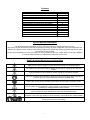
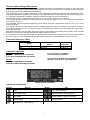
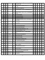
ISO 14001
ISO 9001
Service Manual
Slimline Range
with
FD2-10 Controller
Issued August 2010
Contents
Manual Information & Health & Safety Notes
Environmental Management Policy
Disposal Requirements
Cabinet & Counter Description
Controller Relevance Table & Operation
User Functions
Defrost Operation & Fuzzy Logic
Wiring Diagram for Defrost & Technical Data
Configuration of Parameters
Slimline Controller Default
Individual Unit Controller Parameter Values
Technical Data
Wiring Diagrams & Probe details
Troubleshooting & Notes
1
2
2
3
3-4
4-5
5
6
6
7-10
11-13
14
15-17
18-20
Service Manual Information
The products and all information in this manual are subject to change without prior notice.
We assume by the information given that the person(s) working on these refrigeration units are fully trained and
skilled in all aspects of their workings. Also that they will use the appropriate safety equipment and take or meet
precautions where required.
The service manual does not cover information on every variation of this unit; neither does it cover the installation
or every possible operating or maintenance instruction for the units.
Health & Safety Warnings and Information
Make sure the power supply is turned off before making any electrical repairs.
To minimise shock and fire hazards, please do not plug or unplug the unit with wet
hands.
During maintenance and cleaning, please unplug the unit where required.
Care must be taken when handling or working on the unit as sharp edges may cause
personal injury, we recommend the wearing of suitable PPE.
Ensure the correct moving and lifting procedures are used when relocating a unit.
Do NOT use abrasive cleaning products, only those that are recommended. Never
scour any parts of the refrigerator. Scouring pads or chemicals may cause damage by
scratching or dulling polished surface finishes.
Failure to keep the condenser clean may cause premature failure of the
motor/compressor which will NOT be covered under warranty policy.
Do NOT touch the cold surfaces in the freezer compartment. Particularly when hands
are damp or wet, skin may adhere to these extremely cold surfaces and cause frostbite.
Please ensure the appropriate use of safety aids or Personnel Protective Equipment
(PPE) are used for you own safety.
1
Environmental Management Policy for Service Manuals and Duets.
Product Support and Installation Contractors
Foster Refrigerator recognises that its activities, products and services can have an adverse impact upon the
environment.
The organisation is committed to implementing systems and controls to manage, reduce and eliminate its adverse
environmental impacts wherever possible, and has formulated an Environmental Policy outlining our core aims. A
copy of the Environmental Policy is available to all contractors and suppliers upon request.
The organisation is committed to working with suppliers and contractors where their activities have the potential to
impact upon the environment. To achieve the aims stated in the Environmental Policy we require that all suppliers
and contractors operate in compliance with the law and are committed to best practice in environmental
management.
Product Support and Installation contractors are required to:
1. Ensure that wherever possible waste is removed from the client‟s site, where arrangements are in place all
waste should be returned to Foster Refrigerator‟s premises. In certain circumstances waste may be disposed
of on the client‟s site; if permission is given, if the client has arrangements in place for the type of waste.
2. If arranging for the disposal of your waste, handle, store and dispose of it in such a way as to prevent its
escape into the environment, harm to human health, and to ensure the compliance with the environmental law.
Guidance is available from the Environment Agency on how to comply with the waste management „duty of
care‟.
3. The following waste must be stored of separately from other wastes, as they are hazardous to the environment:
refrigerants, polyurethane foam, and oils.
4. When arranging for disposal of waste, ensure a waste transfer note or consignment note is completed as
appropriate. Ensure that all waste is correctly described on the waste note and include the appropriate six-digit
code from the European Waste Catalogue. Your waste contractor or Foster can provide further information if
necessary.
5.
Ensure that all waste is removed by a registered waste carrier, a carrier in possession of a waste management
licence, or a carrier holding an appropriate exemption. Ensure the person receiving the waste at its ultimate
destination is in receipt of a waste management licence or valid exemption.
6. Handle and store refrigerants in such a way as to prevent their emission to atmosphere, and ensure they are
disposed of safely and in accordance with environmental law.
7. Make arrangements to ensure all staff who handle refrigerants do so at a level of competence consistent with
the City Guilds 2078 Handling Refrigerants qualification or equivalent qualification.
8.
Ensure all liquid substances are securely stored to prevent leaks and spill, and are not disposed of to storm
drains, foul drain, or surface water to soil.
Disposal Requirements
If not disposed of properly all refrigerators have components that can be harmful to the environment. All old
refrigerators must be disposed of by appropriately registered and licensed waste contractors, and in accordance
with national laws and regulations.
2
Slimline Cabinet Range Description
The cabinets are manufactured as a one piece foamed shell with the condensing unit located on the base of the
0
cabinet. All the cabinets conform to ISO Climate Class 5 (40 c with 40% RH) with the temperature being controlled
by a microprocessor with digital temperature display.
The refrigeration system is integral with an air-cooled condensing unit with the refrigerant being distributed into the
evaporator controlled by capillary. This cooled air is circulated through the evaporator, via a fan in the storage area.
To evaporate condensation, the plastic vaporiser tray has a hot gas line that is inserted into it.
0
0
The FSL400H & 800H have a temperature range of +1 c to +4 c with a timed off cycle defrost.
0
0
The FSL400L & 800L are different in that they have a temperature range of -18 c to -21 c with electric defrost set
at 4 times per 24 hours.
0
0
The FSL400M & 800 are models designed for meat chilling and have a temperature range of -2 c to +2 c using
R134a refrigerant.
The coding „FSL‟ means Foster Slimline with the 400/800 afterwards being the respective net capacity in litres. If
the model comes with an H or L this denotes High or Low temperature units as with a G meaning it has glass doors
and M denoting meat.
Both glass and solid doors are fitted with pivot hinges and also both have magnetic door gaskets. Only the solid
doors have recessed door handles whereas the glass is surface mounted.
On the glass door models the interior light, incorporating the on/off switch, is fitted to the top of the storage area at
the front of the unit. All models fitted with lockable swivel castors to the front and swivel castors to the rear.
Controller Relavance Table
st
1 Serial Number
Issued
E5270966
E5270970
Model
400
800
Manufacturer
Date from
09.08.2010
09.08.2010
Controller Operation
FSL400
Probe Air 2.5M SN4K15H1 (00-556248)
Probe Evap 2.5M SN4K15H2 (00-556251)
FD2-10 Controller (00-556241)
LCD 5S Display (00-555992)
LCD5 Connecting Ribbon 3m (00-555814)
(Normally only used on FSL800 Models)
FSL800
Probe Air 4M SN4B40H1 (00-556289)
Probe Evap 4M SN4B40H2B (00-556290)
LCD 5S Display (00-555992)
Indicators and Buttons
Symbol
Reason
Button
Use
Alarm
Info / Set Point Button
Thermostat Output
Manual Defrost / Decrease Button
Fan Output
Increase Button / Manual Activation
Defrost Output
Stand-by Button
Activation of 2
nd
parameter set
3
Display
During normal operation the display shows either the temperature measured or one of the following indicators:
Symbol
Reason
Defrost in progress
Symbol
Reason
Condenser high pressure alarm
Controller in stand-by
Room high temperature alarm
Condenser clean warning
Room low temperature alarm
Door open alarm
Probe T1 failure
Condenser high temperature alarm
Probe T2 failure
Information Menu
The information available in the menu is shown below:
Symbol
Reason
Symbol
Reason
Instant probe 1 temperature
Minimum probe 1 temperature recorded
Instant probe 2 temperature *
Compressor working weeks **
Instant probe 3 temperature *
Keypad state lock
Maximum probe 1 temperature recorded
* Displayed only if enabled (see configuration parameters)
** Displayed only if ACC > 0
User Functions
Start Sequence
For normal operation
Press and hold the
button for 3 seconds then release.
If pressed and held for 5 seconds then released this will start the „Test Sequence‟.
The test function is a defined sequence of events that will follow a prescribed pattern (dependent upon
parameter values). In turn it will operate all electrical elements of the system, simulating a short operating
pattern. This was designed to provide a quick and simple evaluation tool to use either during manufacturing or
when servicing.
To cancel the Test Sequence
Press and release the
button during the test sequence.
If not pressed the test will continue and when complete the controller will wait for 1 min, then resume normal
operation. (The controller will count to 530 then show „end‟. It will then show the current unit temperature)
Access to the menu and information displayed
Press and immediately release button
With button
Press button
or
select the data to be displayed
to display the value
To exit from the menu, press button
or wait for 10 seconds.
Set point: Display and modification
Press button
for at least half a second to display the set point.
By keeping button
pressed, use button
minimum SPL and the maximum SPH limit)
When button
or
is released, the new value is stored.
4
to set the desired value (adjustment is within the
Reset of THI, TLO, CND recordings
With button
or
select the data to be reset
Display the value with button
While keeping button
pressed, use button
.
Standby
When pressing the
button for 3 seconds, will allow the controller to be put on a standby or output control to
be resumed (with SB = YES only). When on Standby
will be displayed.
Selection of second parameter group
It is possible to select control parameters between two different pre-programmed groups, in order for the
fundamental control parameters to be adapted to changing needs. Changeover from Group I to Group II (and
visa versa) may take place Manually by pressing
for 2 seconds (with IISM = MAN), or Automatically when
heavy duty conditions are detected (with IISM = HDD), or when IISM =D12 and the Auxiliary Input D12 is
activated (the activation of D12 selects Group II). If IISM = NON, switchover to Group II is inhibited. The
activation of Group II is signalled by the lighting up of relevant LED on the controller display.
Defrost
Automatic Defrost.
Defrost starts automatically as soon as the time set with parameter DFT has elapsed.
Time Defrost With DFM = TIM defrost takes place at regular intervals when the timer reaches the value
DFT. For example, with DFM = TIM and DFT = 06, a defrost will take place every 6 hours.
Defrost time count backup At the power–up, if DFB = YES, the defrost timer resumes the time count
from where it was left off before the power interruption. Visa versa with DFB=NO, the time count restarts from 0. In stand-by the accumulated time count is frozen.
Defrost type
Once defrost has started, compressor and defrost outputs are controlled according to parameter DTY. If FID
=YES, the evaporator fans are active during defrost.
Resuming Thermostatic Cycle
When defrost is over, if DRN is greater then 0, all outputs will remain off the DRN minutes, in order for the ice to
melt completely and the resulting water to drain.
Manual Defrost
To initiate a manual defrost press and hold the defrost button
for 2 seconds.
Fuzzy Logic
‟Fuzzy Logic’ is an energy saving feature which enables the refrigeration system performance on specific
models to be automatically adjusted during operation, for optimum energy performance whilst maintaining the
correct internal storage temperature. When enabled it works by identifying periods of high and low usage and
applying an appropriate temperature set point and defrost frequency. Additionally the evaporator fan(s) can be
caused to cycle (providing „air stir‟ only) in low usage periods.
„Fuzzy Logic‟ operation is controlled by parameter „IISM‟. Setting the value „HDD‟ for this parameter will cause
the controller to automatically change between the „economy‟ and „performance‟ operating modes (the actual
switching point sensitivity is controlled by parameter „HDS‟). Setting „IISM‟ to „non‟ will disable the „Fuzzy Logic‟
function.
When enabled, and upon the product being switched „On‟, „Fuzzy Logic‟ will automatically start using the
„economy‟ settings to control the operation of the temperature and defrost („SP‟, „HYS‟, and „DFT‟). The
controller will remain operating to the values of these settings unless; through monitoring of the air temperature,
evaporator temperature and door switch (where T2 probe and door switch are fitted), the controller determines
that the usage frequency or temperature variation indicates more demanding operational conditions. In such
circumstances the controller will switch to the „performance‟ mode (utilising parameters „IISP‟, „IIHY‟ and „IIDF‟).
Upon usage or temperature variation reducing sufficiently the controller will revert back to the „economy mode‟.
The evaporator fan operation works in conjunction with, but separate from „Fuzzy Logic‟. Determined by
parameter „FCM‟, and normally set to „TIM‟, the fans will run continuously when the compressor is on, subject to
the door switch operation (where fitted). During the compressor off cycle the fans will operate in an „air stir‟
mode (controlled by parameters „FT1‟, „FT2‟ and „FT3‟). Where „FCM‟ is set to „non‟ the fans will run
continuously. The fan cycle mode during the „performance‟ operation of „Fuzzy Logic‟ is controlled by parameter
„IIFC‟.
5
Parameter Setting Wiring Diagram for Synchronising Defrost Start and Termination
Technical Data
Power Supply
FD2-10
230Vac±10%, 50/60Hz, 3W
Relay Output
Compressor
Defrost
Evap. Fan
Auxiliary Loads 1
16(8) A 240Vac
16(4) A 240Vac
16(4) A 240Vac
8(2) A 240Vac
Measurement Range
-50…120°C, -55…240°F
-50 / -9.9…19.9 / 80°C (NTC 10K Only)
Measurement Accuracy
<0.5°C within the measurement range
CE (Reference norms)
EN60730-1; EN60730-2-9
EN55022 (Class B)
EN50082-1
Input
NTC 10KΩ@25°C
Configuration Parameters
To get access to the parameter configuration menu, press
With button
or
+
for 5 seconds
select the parameter to be modified.
Press button
and hold briefly to display the value. On releasing the button the controller will then
show the next parameter.
By keeping button
pressed, use button
or
to set the desired value. On releasing the button
the controller will store the amended value and then show the next parameter.
To exit from the setup, press button
or wait for 30 seconds.
6
FD2-10 Default Parameter Values
Parameter
1°C
2°C
°F
Description
Readout Scale:
Range -50/-9.9…. 19.9/80°C (With INP = SN4 Only)
Range -50 …. 120°C
Range -55 …. 240°F
SPL
-50 … SPH
Minimum Limit for SP setting
1
SPH
SPL …120°
Maximum limit for SP setting
3
SP
SPL … SPH
Temperature set point to be achieved
2
C-H
REF
HEA
Temperature Control mode:
Refrigeration
Heating
REF
HYS
1 … 10°
Off/On Thermostat differential
3
CRT
0 … 30min
Compressor Rest Time
2
CT1
0 … 30min
Thermostat run time with faulty T1 probe.
(CT1 = 0 output with faulty T1 will always be off)
6
CT2
0 … 30min
Thermostat off time with faulty T1 probe.
(CT2=0 & CT1 = >0 output with faulty T1 will always be on)
4
CSD
0 … 30min
Compressor stop delay after door has been opened
(Only if DS = YES)
1
SCL
Range
Default FD2-10
2°C
Non
TIM
FRO
Defrost Start Mode:
Defrost function is disabled
Regular time defrost
Defrost time elapses only in condition of frost accumulation
DFT
0…99 Hours
Time interval between defrosts
DFB
YES
NO
Defrost timer clock
Following mains interruption, timer resumes count
Following mains interruption, timer restarts from zero
YES
DLI
-50.. 120°
Defrost end temperature
(Only if T2 = EPO)
N/A
DTO
1 … 120min
Maximum defrost duration
20
OFF
ELE
GAS
Defrost Type:
Timed off cycle defrost (compressor and heater off)
Electric heater defrost (compressor off, heater on)
Hot gas defrost (compressor and heater on)
DPD
0 … 240 sec
Evaporator pump down. Timed pause at start of defrost
0
DRN
0 … 30min
Drain down period
2
RT
LT
SP
DEF
Defrost display mode:
Real (actual) air temperature
Last temperature display before start of defrost
The current set point value.
“DEF”
DFM
DTY
DDM
7
TIM
6
OFF
DEF
Defrost display delay period
Time DDM is shown following defrost termination
DDY
0… 60 min
FID
YES
NO
FDD
-50 … 120°
Evaporator fan restart temperature following defrost
(Only if T2 = EPO)
5
FTO
0…120 min
Maximum evaporator fan stop period following defrost
3
FDS
0…120 sec
Minimum evaporator fan stops (following door opening etc)
20
NON
FCM
TMP
Tim
Fans in defrost:
Fans run during defrost
Fans do not run during defrost
Evaporator fan mode during thermostatic control:
Fan(s) run continuously
Temperature based control. When compressor is on, fans are on.
When compressor is off, fans run as long as temperature difference
Te-Ta > FDT. Fans on again with FDH
Time based control. When compressor is on, fans are on. When
compressor is off, fans in accordance to parameters FT1, FT2 and
FT3.
10
YES
TIM
FDT
-120 … 0°
Te-Ta difference for fans to turn off after compressor stopped.
(Only if T2 = EPO and FCM = TMP)
-1
FDH
1 … 120°
Temperature differential for evaporator fan restart.
(Only if T2 = EPO and FCM = TMP)
3
FT1
0 … 180 Sec
Fan stop delay after compressor stop.
15
FT2
0 … 30min
Timed fan stop following FT1
(With FT2 = 0 the fans remain on all the time).
3
FT3
0 .. 30min
Timed fan run following FT2
(With FT3 = 0 and FT2 >0 the fans remain off all the time.
2
ATM
NON
ABS
REL
Alarm threshold configuration:
All temperature alarms are inhibited
The value set in ALA and AHA represent actual alarm set points
The values set in ALR and AHR are alarm differentials which relate
to SP and SP + HYS
REL
ALA
-50 … 120°
Low temperature alarm threshold
AHA
-50 … 120°
High temperature alarm threshold
ALR
-12 … 0°
Low temperature alarm differential
(With ALR = 0 the low temperature alarm is excluded)
-5
AHR
0 … 12°
High temperature alarm differential
(With AHR = 0 the low temperature alarm is excluded)
5
ATI
T1
T2
Alarm probe:
Air temperature probe used for alarm detection
Evaporator temperature probe used for alarm detection
T1
ATD
0… 120min
Delay before alarm temperature warning
90
ADO
0… 30min
Delay before door open alarm warning
8
8
NON
ALR
STP
Operation in case of high condenser alarm (T2 = CND)
High condenser temperature alarm inhibited
Condenser warning – „HC‟ displayed, alarm sounds
As „ALR‟ with compressor stopped and defrosts suspended
AHT
-50 … 120°
Condenser alarm temperature (T2 = CND)
65
ACC
0…52 Weeks
Condenser cleaning period.
(With ACC = 0 condenser cleaning is disabled)
0
AHM
NON
NON
Switchover method to second parameter set:
Second parameter set is excluded
IISM
MAN
IISL
HDD
D12
-50 . IISH
Second parameter set is activated/ deactivated by button
Second parameter activated by „heavy‟ usage
Second parameter set activated by D12 input (D12 = IISM)
Minimum limit for IISP setting
IISH
IISL .. 120°
Maximum limit for IISP setting
1
IISP
IISP…IISH
Temperature set point to be achieved in „Mode 2‟
1
IIHY
1 … 10°
Off/on thermostat differential in „Mode 2‟
3
NON
IIFC
TMP
TIM
Evaporator fan mode during ‘Mode 2’ thermostatic control:
Fans(s) run continuously
Temperature based control. When compressor is on, fans are on.
When compressor is off, fans run as long as temperature difference
Te-Ta>FDT. Fans on again with FDH
Time based control. When compressor is on, fans are on. When
compressor is off, fans in accordance to parameters FT1, FT2 and
FT3.
HDD
1
NON
HDS
1…5
Controller sensitivity for switch over between „Modes‟ and 2.
(1 = minimum, 5 = maximum)
3
IIDF
0 … 99hours
Time interval between defrosts in „Mode 2‟.
6
SB
YES
No
Standby button operation:
Standby button enabled
Standby button disabled
YES
DS
YES
NO
Door switch operation (switch made when door closed):
Door switch enabled
Door switch disabled
YES
NON
HPS
IISM
RDS
DS2
Configuration digital input operation:
Digital input 2 not activated
High pressure alarm when contact opens
„Mode 2‟ parameters active when contact closes
Defrost initiated when contact closes
Second door switch function (operated „in series‟ with DS)
NON
NON
Light control mode:
Digital input 2 not activated
DI2
MAN
LSM
DOR
NDR
Light output operation is activated/deactivated by button
(With OA1 = LGT)
Light output is switched on when door is opened
(With OA1 = LGT and DS = YES)
Light output is switched off when door is opened.
(With OA1 = LGT and DS = YES)
9
NON
OA1
NON
0-1
LGT
AL0
AL1
Auxiliary relay operation:
Output disabled (always off)
Contacts open/close with standby/on mode
Output enabled for light control
Contacts open when an alarm condition occurs
Contacts close when an alarm condition occurs
(Relay contacts open when in standby mode)
NON
SN4
INP
SN4
ST1
Temperature sensor(s) type:
10k NTC type thermistor (red writing)
1k PTC type thermistor (Black Writing)
OS1
-12.5...12.5°C
Air temperature probe (T1) offset.
NON
EPO
CND
T2 Probe function:
T2 Probe disabled
Evaporator temperature monitoring
Condenser temperature monitoring
OS2
-12.5…12.5°C
T2 probe temperature offset
0
TLD
1 … 30min
Delay for min (TLO) and max. (THI) temperature logging
10
SIM
0 … 100
Display Slowdown
5
ADR
1… 255
FD2-10 address for PC communication
1
T2
10
0
NON
253
SCL
1C
200
SPL
-50
o
o
Mid
o
Max
o
Description
FSL400M
&
FSL800M
Min
FSL800L
Par
FSL800H
Reg
FSL400L
FOSTER FD2-10
FSL400H
Individual Unit Controller Parameter Values
C
I
C
I
O
2°C
2°C
2°C
2°C
2C
o
F
2C
Readout scale.
…..
SPH
Minimum limit for SP setting.
1
-21
1
-21
-2
o
202
SPH
SPL
…..
120
Maximum limit for SP setting.
3
-19
3
-19
0
204
SP
SPL
…..
SPH
Temperature set point to be achieved.
1
-21
1
-21
-2
268.1
C-H
REF
…..
HEA
Temperature control mode.
REF
REF
REF
REF
REF
Off / On thermostat differential.
4
4
4
4
2
o
o
214
HYS
1
…..
10
216
CRT
0 min
…..
30 min
Compressor rest time.
2
2
2
2
2
217
CT1
0 min
…..
30 min
Thermostat run time with faulty T1 probe.
6
6
6
6
6
218
CT2
0 min
…..
30 min
Thermostat off time with faulty T1 probe.
4
4
4
4
4
219
CSD
0 min
…..
30 min
Compressor stop delay after door has been opened. (Only if DS = YES).
1
1
1
1
1
220
DFM
FRO
TIM
TIM
TIM
TIM
TIM
DFT
6
6
6
6
6
268.4
DFB
TIM
99
hours
YES
Defrost start mode.
221
NON
0
hours
NO
YES
YES
YES
YES
YES
Defrost end temperature (Only if T2 = EPO).
20
20
20
20
20
Maximum defrost duration.
20
20
20
20
20
o
…..
…..
o
206
DLI
-50
…..
120
223
DTO
1 min
…..
120 min
Time interval between defrosts.
Defrost timer clock.
224
DTY
OFF
ELE
GAS
OFF
ELE
OFF
ELE
ELE
225
DPD
0 sec
…..
240 sec
Evaporator pump down. Timed pause at start of defrost.
0
0
0
0
0
226
DRN
0 min
…..
30 min
Drain down period.
2
2
2
2
2
227
DDM
RT
SP, DEF
LT
DEF
DEF
DEF
DEF
DEF
228
DDY
0 min
…..
60 min
10
10
10
10
10
267.5
FID
NO
…..
YES
YES
NO
YES
NO
NO
o
Evaporator fan restart temperature following defrost. (Only if T2 = EPO).
5
0
5
0
0
3
3
3
3
3
o
Defrost type.
Defrost display mode.
Defrost display delay period.
Fans in defrost.
207
FDD
-50
…..
120
229
FTO
0 min
…..
120 min
Maximum evaporator fan stop period following defrost.
237
FDS
0 sec
…..
120 sec
Minimum evaporator fan stop (following door opening etc.).
230
FCM
NON
TIM
TMP
Evaporator fan mode during thermostatic control.
11
20
20
20
20
20
TIM
TIM
TIM
TIM
TIM
o
o
…..
0
1
…..
120
FT1
0 sec
…..
180 sec
235
FT2
0 min
…..
30 min
236
FT3
0 min
…..
30 min
238
ATM
NON
REL
ABS
…..
o
o
232
FDT
-120
233
FDH
234
208
209
ALA
AHA
o
o
-50
o
-50
o
o
120
…..
120
o
Te-Ta difference for fans to turn off after compressor stopped. (Only if T2
= EPO and FCM = TMP).
Temperature differential for evaporator fan restart. (Only if T2 = EPO and
FCM = TMP).
Fan stop delay after compressor stop.
Timed fan stop following FT1. (With FT2 = 0 the fans remain on all the
time).
Timed fan run following FT2. (With FT3 = 0 & FT2 > 0 the fans remain off
all the time).
Alarm threshold configuration.
-1
-1
-1
-1
-1
3
3
3
3
3
15
15
15
15
15
0
0
0
0
0
2
2
2
2
2
REL
REL
REL
REL
REL
Low temperature alarm threshold.
-2
-2
-2
-2
-2
High temperature alarm threshold.
Low temperature alarm differential. (With ALR = 0 the low temperature
alarm is excluded).
High temperature alarm differential. (With AHR = 0 the low temperature
alarm is excluded).
Alarm probe.
8
8
8
8
8
-5
-5
-5
-5
-5
5
5
5
5
5
T1
T1
T1
T1
T1
239
ALR
-12
…..
0
240
AHR
0
o
…..
12
241
ATI
T1
…..
T2
242
ATD
0 min
…..
120 min
Delay before alarm temperature warning.
90
90
90
90
90
243
ADO
0 min
…..
30 min
Delay before door open alarm warning.
8
8
8
8
8
244
AHM
NON
STP
ALR
NON
NON
NON
NON
NON
65
65
65
65
65
0
0
0
0
0
HDD
HDD
HDD
HDD
HDD
Minimum limit for IISP setting.
1
-21
1
-21
-2
210
AHT
245
ACC
247
IISM
201
IISL
o
-50
0
weeks
NON
o
-50
…..
o
o
HDD, DI2
120
52
weeks
MAN
…..
IISH
o
…..
Operation in case of high condenser alarm (T2 = CND).
Condenser alarm temperature (T2 = CND).
Condenser cleaning period. (With ACC = 0 condenser cleaning is
disabled).
Switchover method to second parameter set.
203
IISH
IISL
…..
120
Maximum limit for IISP setting.
1
-21
1
-21
0
205
IISP
IISL
…..
IISH
Temperature setpoint to be achieved in 'Mode 2'.
1
-21
1
-21
-2
Off / On thermostat differential in 'Mode 2'.
4
4
4
4
2
NON
NON
NON
NON
NON
3
3
3
3
3
6
6
6
6
6
Standby button operation.
YES
YES
YES
YES
YES
NO
NO
NO
NO
NO
o
o
215
IIHY
1
…..
10
231
IIFC
NON
TIM
TMP
246
HDS
1
…..
5
222
IIDF
…..
268.7
SB
0
hours
NO
…..
99
hours
YES
268.0
DS
NO
…..
YES
Door switch operation (switch made when door closed).
251
DI2
NON
IISM, RDS, DS2
HPS
Configurable digital input operation.
NON
NON
NON
NON
NON
248
LSM
NON
DOR, NDR
MAN
Light control mode.
NON
NON
NON
NON
NON
Evaporator fan mode during 'Mode 2' thermostatic control.
Controller sensitivity for switch over between 'Modes' 1 and 2. (1 =
minimum, 5 = maximum).
Time interval between defrosts in 'Mode 2'.
12
249
OA1
NON
LGT, AL0, AL1
0-1
Auxiliary relay operation.
0-1
0-1
0-1
0-1
0-1
268.2
INP
…..
SN4
Temperature sensor(s) type.
SN4
SN4
SN4
SN4
SN4
256
OS1
…..
12.5 C
0
0
0
0
0
250
T2
EVP
CND
NON
EVP
NON
EVP
EVP
251
OS2
…..
12.5 C
T2 probe temperature offset.
0
0
0
0
0
252
TLD
ST1
o
12.5 C
NON
o
12.5 C
1 min
…..
30 min
Delay for min. (TLO) and max. (THI) temperature logging.
10
10
10
10
10
254
SIM
0
…..
100
Display slowdown.
5
5
5
5
5
255
ADR
1
…..
255
FD2-10 address for PC communication
1
1
1
1
1
o
o
Air temperature probe (T1) offset.
T2 probe function.
Parameters ALA and AHA will not be visible when ATM is set at REL.
Parameters ALR and AHR will not be visible if ATM is changed to ABS.
13
Technical Data Slimline Cabinets
Model
FSL400H
FSL400L
FSL400M
FSL800H
FSL800L
FSL800M
Storage Temp
0
0
+1 c to +4 c
0
0
-18 c to -21 c
0
0
-2 c to +2 c
0
0
+1 c to +4 c
0
0
-18 c to -21 c
0
0
-2 c to +2 c
Gas
Gas Charge
Compressor
Capillary
Defrost Type
Voltage
R134a
R404a
R134a
R134a
R404a
R134a
310 grms
285 grms
310 grms
400 grms
350 grms
400 grms
FR75GX
SC15CL
FR75GX
SC12GX
SC21CLX
SC12GX
3.0m x 0.042
2.5m x 0.042
3.0m x 0.042
3.0m x 0.054
3.0m x 0.054
3.0m x 0.054
Timed Off Cycle
Electric
230/50/1
230/50/1
230/50/1
230/50/1
230/50/1
230/50/1
Timed Off Cycle
Electric
Power Consumption
Watts
Amps
280
2.1
584
3.8
520
758
3.6
4.1
Fuse Rating
13amps
13amps
13amps
13amps
Technical Data Slimline Cabinets with R290 Refrigerant
Model
FSL400H
Storage Temp
0
0
+1 c to +4 c
Gas
Gas Charge
Compressor
Capillary
Defrost Type
Voltage
R290
150grms
TL5CNX
3.0m x 0.042
Timed Off Cycle
230/50/1
14
Power Consumption
Watts
Amps
280
2.1
Fuse Rating
13amps
Slimline High Temp (Integeral and Remote Models) Wiring Diagram
15
Slimline Low/Meat Temp (Integeral and Remote Models) Wiring Diagram
16
Air and Evaporator Probe Details / Diagram
Probe Air 2.5M SN4K15H1 (00-556248)
Probe Evap 2.5M SN4K15H2 (00-556251)
17
Troubleshooting
Problem
Compressor will not start
The temperature is too cold
Possible Cause
No voltage in socket
Electrical conductor or wires may be
cut
Defective electrical component:
thermostat, relay, thermal protector etc
Use voltmeter to check
Use ohmmeter to check for continuity
Replace defective component
Compressor motor has a winding open
or shorted
Measure ohmic resistance of main and
auxiliary winding using ohmmeter.
Compare with correct values
Compressor stuck
Change compressor
Temperature control contacts are open
Incorrect wiring
Fuse blown or circuit breaker tripped.
Power cord unplugged
Controller set too high
Cabinet in defrost cycle
Repair or replace the contacts
Check wiring diagram and correct
Replace fuse or reset circuit breaker
Plug in power cord.
Set controller to lower temperature.
Wait for defrost cycle to finish
Controller is set at a very cold position
Controller does not disconnect the
condensing unit
Control contacts are stuck closed
The temperature is not cold enough
Solution
Set to warmer position and check if the
compressor stops according to
controllers operating range.
Check the insulation of the thermostat.
If problem persists, change the
thermostat
Change the control. Check amperage
load
Defective or incorrect temperature
control
Determine correct control and replace.
Controller is set at a very warm
position
Adjust to colder setting
Condenser is dirty
Clean condenser
The refrigerator has been placed at an
inadequate location
The unit must not be near stoves,
walls that are exposed to the sun, or
places that lack sufficient air flow.
Compressor is inefficient or there is a
high pressure due to the air in the
system
If there is air in the system, purge and
recharge
Iced up evaporator coil
Restriction in system
The refrigerator has been used
improperly
Too many door openings
Excessive heat load placed in cabinet
The refrigerator has been overcharged
with the refrigerant gas
18
Check temperature control, refrigerant
charge, and defrost mechanism.
Remove all ice manually and start
over.
Locate exact point of restriction and
correct
The shelves must never be covered
with any type of plastic or other
material that will block the circulation
of cold air within the refrigerator.
Advise user to decrease if possible
Advise user not to put in products that
are too hot.
Check to see if condensation or ice
crystals have formed on the suction
line. If so, charge with the correct
amount of gas.
Fuse blown or circuit breaker tripped
Find the location of gas leak in order to
seal and replace the defective
component. Change the drier. Perform
a good vacuum and recharge unit.
Check electrical connections and
make sure that the fan blade isn‟t
stuck. Replace the fan motor if it
doesn‟t work.
Re-arrange product to allow for proper
air flow. Make sure there is at least
four inches of clearance from
evaporator.
Replace fuse or reset circuit breaker.
Wires or electrical components are in
direct contact with metallic parts.
Check for appropriate insulation on the
connections of each component.
The refrigerator is not properly levelled
Check if the noise goes away after you
level the refrigerator
The refrigerant gas is leaking
The evaporator and/or condenser fans
are not working
Blocking air flow
Electrical Shocks
Noise
The condenser is not fastened
correctly. Copper tubing is in contact
with metal
The evaporator and/or condenser fans
are loose
Compressor has an internal noise
Loose part(s)
Extreme condensation inside the
refrigerator
The refrigerator had been placed at an
inadequate location
Set the controller to a warmer position
& check to see if compressor stops as
should.
This type of occurrence is caused by
local climatic conditions and not by the
refrigeration unit.
Check the door and/or the magnetic
gasket. Adjust the door hinges if
needed; replace the gasket if broken.
The unit must not be near sources that
produce too much heat.
The light switch is “off” position
Press the light switch to “on” position
Controller is set at a very cold position
The outside environment‟s relative
humidity is very high (over 75%)
The refrigerator door wont shut
completely
No illumination (Glass door models
only)
False contact on the light switch, the
fluorescent tube, or the ballast
Light switch, ballast and/or fluorescent
tube are damaged
Condensing unit runs for
long periods of time
While the compressor is working,
check to see if metal parts are in
contact with one another and/or if the
screws that fasten the condenser are
tightened.
Check if the fans are securely
fastened. Also, check if the fan blades
are loose, broken or crooked. If so,
change the faulty blade.
If the noise persists after all other
measures have been taken, it may be
originating from the compressor.
Locate and tighten loose part(s)
Excessive amount of warm product
placed in cabinet
Prolonged door opening or door ajar
Door gasket(s) not sealing properly
19
Inspect all connections
Replace the damaged component.
Advise user to leave adequate time for
products to cool down
Advise user to ensure doors are
closed when not in use and to avoid
opening doors for long periods of time.
Ensure gaskets are snapped in
completely. Remove gasket and wash
with soap and water. Check condition
of gasket & replace if necessary
Dirty condenser coil
Clean condenser coil
Evaporator coil iced over
Unplug unit and allow coil to defrost.
Make sure thermostat is not set too
cold. Ensure that door gasket(s) are
sealing properly. Select manual
defrost and ensure system works.
Notes
20
Foster European Operations
France
Foster Refrigerator France SA
Tel: (33) 01 34 30 22 22. Fax: (33) 01 30 37 68 74.
Email: [email protected]
Germany
Foster Refrigerator Gmbh,
Tel: (49) 781 990 7840. Fax (49) 781 990 7844.
Email: [email protected]
Foster Refrigerator
Oldmedow Road
Kings Lynn
Norfolk
PE30 4JU
Tel: 0843 216 8833
Fax: 0843 216 4707
Website: www.fosterrefrigerator.co.uk
Email: [email protected]
a Division of „ITW (UK) Ltd‟
SLIMLINE FD2-10/SM 08/10
21