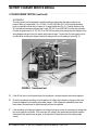
1
Electronic Service
Manuals
This electronic document is provided as a service to our customers. We do not create the contents of the information contained in
this document. Should you have detailed questions pertaining to
the information contained in this document, you may contact Michco,
or the manufacturer which provided the original information in this
electronic deliverable. Michco’s only part in this electronic deliverable was the electronic assembly process.
You may contact Michco through the following methods:
Phone (517) 484-9312 or (800) 331-3339 MI, OH, IN only
2011 N. High St. -- Lansing, Michigan -- 48906
Fax: (517) 484-9836
Email: [email protected]
Web site: www.Michco.Com
Parts Web site: www.FloorMachineParts.Com
Order Parts on Line at:
www.FloorMachineParts.Com
Directly to Parts & Service:
By Email: [email protected]
By Fax: (517) 702-2041
By Voice: Use numbers above.
Serving the Cleaning Industry Since 1922
Notice: All copyrighted material remains property of original owners, all trademarks are property of respective
owners. Manuals are subject to Manufacturer’s reproduction limitations. Originals or reproductions were provided
by manufacturers through a request. We make no warranty as to the correctness of information provided in this
document and you assume all risk.
Battery Chargers
SERVICE MANUAL / PARTS LIST
AUTOMATIC Advance MODELS 56206980, 56206981, 56372947, 56388109,
56395101, 56388502, 56388120, 56409494, 56411058, 56411643, 56409788,
56205983, 56412272, 56206973, 56372203, 56372190, 56388119
Lester MODELS 56031407, 56632342, 56638431, 56638436, 56638439,
56638440, 56632293, 56031403, 56031405, 56031408
MANUAL MODELS (obsolete) 56206975, 56372945, 56372955
Revised 8/00 Form Number 56041170
FORM NO. 56041170 / BATTERY CHARGER SERVICE MANUAL / PARTS LIST - 45
BATTERY CHARGER SERVICE MANUAL / PARTS LIST
_______________________________________________________________________________________
TABLE OF CONTENTS
Safety ......................................................................................................................... 2
General Information .................................................................................................... 3
Transformer / Rectifier or Power Section.................................................................... 3
On / Off Control Section ............................................................................................. 4
Automatic and Manual Timer Battery Charger Troubleshooting ................................. 5
Manual Charger PN 56206975 ................................................................................. 16
Automatic Chargers PN 56206980 ........................................................................... 17
Manual Charger PN 56372945 ................................................................................. 18
Automatic Charger PN 56372947............................................................................. 19
Automatic Charger PN 56388109............................................................................. 20
Manual Charger PN 56372955 ................................................................................. 21
Automatic Charger PN 56395101 (replaces PN’s 56372947 & 56395347) .............. 22
Automatic Charger PN 56388502............................................................................. 23
Automatic Charger PN 56388120............................................................................. 24
Automatic Charger PN 56409494............................................................................. 25
Automatic Charger PN 56411058 ............................................................................. 26
Automatic Charger PN 56411643 ............................................................................. 27
Automatic Charger PN 56409788............................................................................. 28
Automatic Charger PN 56205983 (replaces PN 56206981)..................................... 29
Automatic Charger PN 56412272............................................................................. 30
Automatic Charger PN 56206973............................................................................. 31
Automatic Charger PN 56372203............................................................................. 32
Automatic Charger PN 56372190............................................................................. 33
Automatic Charger PN 56388119 ............................................................................. 34
Automatic Charger PN 56031407............................................................................. 35
Automatic Charger PN 56632342............................................................................. 36
Automatic Charger PN 56638431............................................................................. 37
Automatic Charger PN 56638436............................................................................. 38
Automatic Charger PN 56638439............................................................................. 39
Automatic Charger PN 56638440............................................................................. 40
Automatic Charger PN 56632293............................................................................. 41
Automatic Charger PN 56031403............................................................................. 42
Automatic Charger PN 56031405............................................................................. 43
Automatic Charger PN 56031408............................................................................. 44
revised 8/00
FORM NO. 56041170 / BATTERY CHARGER SERVICE MANUAL / PARTS LIST - 1
BATTERY CHARGER SERVICE MANUAL
________________________________________________________________________________________________________________________________________________________________________________________________________________________________________________________________________
SYMBOLS
Nilfisk-Advance uses the symbols below to signal potentially dangerous conditions. Always read this information carefully and take the necessary steps to protect personnel and property.
DANGER!
Is used to warn of immediate hazards that will cause severe personal injury or death.
WARNING!
Is used to call attention to a situation that could cause severe personal injury.
CAUTION!
Is used to call attention to a situation that could cause minor personal injury or damage to the machine or other
property.
________________________________________________________________________________________________________________________________________________________________________________________________________________________________________________________________________
GENERAL SAFETY INSTRUCTIONS
DANGER!
HIGH VOLTAGE! With the charger on, the internal charger capacitor voltage is approximately 650
volts.
WARNING!
Do not operate the charger if it is malfunctioning. Personal injury or property damage could result.
Remove all jewelry when working near electrical components.
CAUTION!
To be able to use the troubleshooting guide safely and effectively it is important to read this manual
completely before beginning any tests.
Incorrect assembly may result in a risk of electric shock or fire.
Always unplug the electrical cords, first from the AC outlet and then from the charger receptacle
before attempting any repairs or service to the charger.
REPAIRS BY QUALIFIED PERSONNEL ONLY. NOTE: Modifying this charger for use other than that
for which it was intended, repairs by persons not qualified, or not using original equipment replacement parts will void the manufacturer’s warranty and liability.
2 - FORM NO. 56041170 / BATTERY CHARGER SERVICE MANUAL / PARTS LIST
BATTERY CHARGER SERVICE MANUAL
________________________________________________________________________________________________________________________________________________________________________________________________________________________________________________________________________
GENERAL INFORMATION
The Nilfisk-Advance Battery Chargers are designed to recharge deep-cycling lead acid batteries. A
ferroresonant transformer is used to provide a highly reliable, line compensating unit with a minimum of
moving parts, designed for long trouble-free service. The chargers are constructed so that all parts can be
tested and replaced with basic hand tools. In addition, an analog multimeter of 10,000 ohms per volt sensitivity
or better is required.
The Nilfisk-Advance battery charger is comprised of two basic sections; the transformer/rectifier or power
section, and the on/off control section.
________________________________________________________________________________________________________________________________________________________________________________________________________________________________________________________________________
TRANSFORMER / RECTIFIER OR POWER SECTION
The power or charging section consists of a transformer with its specified part number and rating capacitor and
rectifying diodes attached to a heat sink. The ammeter displays charging current and the fusing provides
electrical protection.
The transformer consists of primary coil or coils separated from the capacitor and secondary coils by a stack
of transformer grade steel pieces called a shunt pack. The transformer coils are wound with high temperature
double insulated magnet wire. The leads are covered with tan or black sleeving and all termination connectors
are crimped and soldered. The transformer must be properly connected in accordance with the correct wiring
diagram for each specific part number charger.
The capacitor functions in combination with the specific transformer to provide the correct charger output with
variation in AC line voltage. The correct part number and rating capacitor as listed on the parts list must be
used with the correct part number transformer and charger.
CAUTION!
Use only the correct part number and rating capacitor. Use of a different capacitor may result in
improper charging, capacitor failure, transformer burnout and / or battery damage.
The rectifier diodes are attached to a heatsink plate or bracket that is fastened to, but electrically isolated from,
the charger chassis. Connection points are provided on the heatsink assembly with diodes. One connection
point is to the heatsink plate itself or a tab attached to it, the remaining connections are to individual diode tabs
or leads. More than one lead can be attached to each connection point and the heatsink assembly with diodes
must be the right part number and connected in accordance with the correct wiring diagram for the specific
part number charger.
The ammeter needle deflects in response to current flow indicating charge current. Connections to the
ammeter terminals are either push on or with jam nuts. When tightening the jam nuts, insure the threaded stud
does not turn, or damage to the ammeter can occur. Use only the correct ammeter as specified in the appropriate wiring diagram and parts list.
FORM NO. 56041170 / BATTERY CHARGER SERVICE MANUAL / PARTS LIST - 3
BATTERY CHARGER SERVICE MANUAL
________________________________________________________________________________________________________________________________________________________________________________________________________________________________________________________________________
TRANSFORMER / RECTIFIER OR POWER SECTION (continued)
The fusing consists of a fuse link in series with each diode and provides overcurrent protection should one or
both diodes fail in the shorted mode. When both fuses or fuse links blow, this is usually due to a reverse
polarity connection to the batteries. Either two individual fuseholders with fuses or a single dual element fuse
assembly provides this protection. The fuse assembly consists of a double ended fuse wire visable through a
transparent bubble mounted on the front panel. Each half of the fuse wire serves as an individual fuse element. After correcting the reason for the fuse blowing, replace the fuse or fuse assembly only with the correct
rating and part number in accordance with the correct wiring diagram and parts list for the specific part number
charger.
________________________________________________________________________________________________________________________________________________________________________________________________________________________________________________________________________
ON/OFF CONTROL SECTION
The ON/OFF control is provided by either a manually set hours of charge timer or the fully automatic battery
condition sensing electronic timer kit.
The fully automatic timer section has three main components.
The, “Electronic Timer Kit”, consist of state of the art electronic circuitry on a printed circuit board contained in
a protective sheet metal housing.
The “Control Cable Assembly”, has a polarized edge connector that mates with the circuit board pads on the
rear of the electronic timer kit. The wires attached to the edge connector are the correct length, position and
color to be connected in accordance with the proper wiring diagram for each specific part number charger.
The “On/Off Control Relay”, responds to signals from the electronic timer kit to either turn the AC power on or
off to the transformer of the power section. The relay terminal nomenclature is printed on each relay case and
should be connected according to the correct wiring diagram for each specific part number charger.
The manually set hours of charge timer is a simple electric clock motor operated on/off switch that turns off
after the preset number of hours has elapsed. The push on connections are numbered and must be connected according to the correct wiring diagram for each specific part number charger.
4 - FORM NO. 56041170 / BATTERY CHARGER SERVICE MANUAL / PARTS LIST
BATTERY CHARGER SERVICE MANUAL
________________________________________________________________________________________________________________________________________________________________________________________________________________________________________________________________________
AUTOMATIC TIMER BATTERY CHARGER TROUBLESHOOTING
Proper functioning of the Automatic Battery Charger is indicated by the following sequence of events. Three to
five seconds after the DC plug is connected to the charger receptacle the control relay “clicks” on, the transformer hums and the ammeter registers proper charge.
Proper diagnosing and repair requires identifying the malfunction from the following list, performing the indicated tests and repairing or replacing the malfunctioning items.
Malfunction Descrip1ion
Test Procedures / Section Number
Relay does not “click” on when DC plug is
connected to the charger receptacle.
Test for complete electrical connection to
batteries / 1.
Test for proper functioning of automatic timer
components / 2.
Relay “clicks” on, but transformer does not
hum.
Test AC power circuit / 3.
Transformer hums but no ammeter indication.
Test Charger DC Circuit / 7.
Test Fuses and Diodes / 6.
Test Capacitor / 4.
Test Transformer / 5.
Transformer hums but charger output is low.
Test Fuses and Diodes / 6.
Test Transformer / 5.
Fuse blows as soon as DC plug is connected
to the charger receptacle.
Test Charger DC Circuit / 7.
Test Fuses and Diodes / 6.
Ammeter remains pegged at maximum
charge for more than 30 minutes.
Check Battery System Voltage / 8.
Charger does not turn off.
Test Automatic Timer Section for “Does Not
Turn Off” / 9.
WARNING!
Do not touch the battery terminals or contacts on the charging plug. An electrical shock could result.
FORM NO. 56041170 / BATTERY CHARGER SERVICE MANUAL / PARTS LIST - 5
BATTERY CHARGER SERVICE MANUAL
________________________________________________________________________________________________________________________________________________________________________________________________________________________________________________________________________
MANUAL TIMER BATTERY CHARGER TROUBLESHOOTING
Proper functioning of the charger is indicated by the following sequence of events. When the timer knob is
turned to “ON”, the transformer hums and the ammeter registers proper charge.
Proper diagnosing and repair requires identifying the malfunction from the following list, performing the indicated tests and repairing or replacing the malfunctioning items.
Malfunction Description
Test Procedures / Section Number
Transformer does not hum when the timer is
turned to “ON”.
Test AC Power Circuit / 3.
Transformer hums but no ammeter indication.
Test for complete electrical connection
to battery system / 1.
Test Charger DC Circuit / 7.
Test Fuses and Diodes / 6.
Test Capacitor / 4.
Test Transformer / 5.
Transformer hums but charger output is low.
Test Fuses and Diodes / 6.
Test Transformer / 5.
Fuse blows as soon as the charger is
connected to the batteries.
Test Fuses and Diodes / 6.
Ammeter remains pegged at maximum charge
for more than 30 minutes.
Check Battery System Voltage / 8.
Charger does not turn off.
Replace Manual Timer.
WARNING!
Do not touch the battery terminals or contacts on the charging plug. An electrical shock could result.
6 - FORM NO. 56041170 / BATTERY CHARGER SERVICE MANUAL / PARTS LIST
BATTERY CHARGER SERVICE MANUAL
________________________________________________________________________________________________________________________________________________________________________________________________________________________________________________________________________
1-CHECKING FOR COMPLETE ELECTRICAL CONNECTION TO THE BATTERIES
A
Measure and record battery system voltage at the battery posts of the machine. Connect the positive (+)
voltmeter lead to the positive (+) battery system post and the negative (-) voltmeter lead to the negative
(-) battery system post.
B
Measure and record battery voltage at the charger receptacle. If no voltage is measured or the voltage
measured is lower than the voltage measured in step A, repair or replace connections to batteries in
machine.
C
See Figure 1. With both the AC cord and the charging plug disconnected, remove the cover from the
charger. Connect the positive voltmeter lead to the same point inside the charger where the white (+) DC
cord lead connects. Connect the negative voltmeter lead to the same point inside the charger where the
black (-) DC cord lead connects.
FIGURE 1. Testing for complete electrical connection to the battery system.
D
Connect the DC Output cord to the charger receptacle and record the voltage measured. It should be the
same voltage as measured in step A.
E
If no voltage is measured or the voltage measured is lower than the voltage measured in step A, repair or
replace the receptacle, charger plug and / or the cordset and re-test.
FORM NO. 56041170 / BATTERY CHARGER SERVICE MANUAL / PARTS LIST - 7
BATTERY CHARGER SERVICE MANUAL
________________________________________________________________________________________________________________________________________________________________________________________________________________________________________________________________________
2-TEST FOR PROPER FUNCTIONING OF AUTOMATIC TIMER COMPONENTS
A
With both the AC cord and the charging plug disconnected, remove the cover from the charger. Verify
that the charger is wired correctly according to appropriate wiring diagram for the specific part number
charger.
B
Remove the retaining screws and slide the
automatic timer kit out the front of the
charger. Disconnect the edge connector
from the automatic timer kit and insert the
test kit (Fig. 2). Connect the DC plug to the
charging receptacle and listen for the relay
to “click” on. If the relay now “clicks” on,
install a new automatic timer kit and re-test.
If the relay does not “click” on, continue with
the next test.
FIGURE 2. Insert the test kit.
C
Measure DC voltage across the pads on the
test kit that the red (Positive) and black
(Negative) wires contact (Fig. 3). The meter
should read the same battery voltage as
recorded in 1-C. If no voltage is measured
or the voltage measured is lower, repair or
replace the control cable assembly and
retest.
D
Measure DC voltage across the pads on the
test kit that the black (Negative) and brown
(Positive) wires contact. It should read the
same battery voltage as recorded in 2-C. If
no voltage is measured install a new control
relay and retest.
FIGURE 3. Measure battery system voltage
at the test kit pads.
8 - FORM NO. 56041170 / BATTERY CHARGER SERVICE MANUAL / PARTS LIST
BATTERY CHARGER SERVICE MANUAL
________________________________________________________________________________________________________________________________________________________________________________________________________________________________________________________________________
3-TEST AC POWER CIRCUIT
A
Measure AC line voltage at the outlet to be sure the correct AC voltage for the specific part number
charger is present (115 VAC, or 230 VAC). If the correct AC power is present, disconnect the AC plug
and the charging plug.
B
Adjust the multimeter to the low resistance scale (R X 1) or use a low voltage continuity tester. Connect
the tester leads to the flat prongs on the AC plug.
•
MANUAL TIMER CHARGER
Turn the timer knob to “ON” and note the response. The circuit should be complete when the timer knob
is turned to “ON”, (Fig. 4) and open when the timer knob is turned to “OFF”.
FIGURE 4. Test AC circuit for continuity.
•
AUTOMATIC TIMER CHARGER
Connect the charging plug to the charging receptacle and listen for the control relay to “click” on, 2 to 5
seconds after connection.
•
The circuit should be open before the relay “clicks” on and the circuit should be complete after the relay
“clicks” on.
C
If the circuit does not test as described, individually check the AC cord, manual timer contacts, control
relay contacts, primary transformer coil(s) and all connections.
DANGER!
HIGH VOLTAGE! With the charger on, the charger capacitor voltage is approximately 650 volts AC.
Use extreme caution when working near the capacitor terminals.
FORM NO. 56041170 / BATTERY CHARGER SERVICE MANUAL / PARTS LIST - 9
BATTERY CHARGER SERVICE MANUAL
________________________________________________________________________________________________________________________________________________________________________________________________________________________________________________________________________
4-TEST THE CAPACITOR
WARNING!
It is possible for the capacitor to not be fully discharged. To test for this, adjust your meter to the
highest DC voltage scale and touch the test leads to the capacitor terminals and note the reading. If
the meter needle deflects in the wrong direction reverse the test leads and repeat. If the capacitor was
not fully discharged a voltmeter reading will indicate this. Continue holding the voltmeter leads on the
capacitor terminals until the voltage reading drops to zero.
A
Using the analog ohmmeter adjust the scale to R X 10,000 (1 Ok) Ohms. Loosen the capacitor clamp
and carefully remove both transformer leads from the capacitor terminals so the wires do not break.
Touch the ohmmeter leads to the capacitor terminals and note the results. Reverse the test leads, repeat
the test and compare to the following:
•
GOOD CAPACITOR: When the ohmmeter leads are connected to the capacitor terminals the meter
needle bumps up to mid scale and quickly coasts back to high resistance (∞).
•
OPEN CAPACITOR: When the ohmmeter leads are connected to the capacitor the meter needle does
not move and stays at high resistance (∞). A bulge in the top of the capacitor may be visable if the
capacitor has failed “OPEN”.
•
SHORTED CAPACITOR: When the ohmmeter leads are connected to the capacitor terminals, the meter
needle jumps to full scale, zero ohms and remains there.
B
If the capacitor is “Open” or “Shorted” it must be replaced.
CAUTION!
Use only the correct part number and rating capacitor as specified on the correct parts list for the
specific part number charger. The use of a different part number or rating capacitor may result in
improper charging, capacitor failure, transformer burnout, and / or battery damage.
10 - FORM NO. 56041170 / BATTERY CHARGER SERVICE MANUAL / PARTS LIST
BATTERY CHARGER SERVICE MANUAL
________________________________________________________________________________________________________________________________________________________________________________________________________________________________________________________________________
5-TRANSFORMER TESTING
Testing the transformer consists of measuring the AC voltage across the transformer secondary leads that
connect to the diodes. This voltage is measured first with the capacitor disconnected and compared to the
voltage measured with a capacitor connected that has been tested and found good.
DANGER!
HIGH VOLTAGE! With the charger operating, the charger capacitor voltage is approximately 650 volts
AC. Use extreme caution when working near capacitor terminals.
A
Disconnect the transformer secondary coil leads #1 and #4 (TAN SLEEVING) from the diode terminals.
Loosen the capacitor strap and carefully disconnect the transformer capacitor coil leads from the capacitor terminals.
B
Refer to the transformer test voltages diagram on the wiring diagram and parts list page for the specific
part number charger and adjust the voltmeter to an appropriate AC voltage range. Attach the meter test
leads to the identified transformer coil leads.
C
Checking to be sure for personal safety, and that no leads have been accidentally allowed to short, follow
the instructions below to energize the transformer primary.
•
MANUAL TIMER CHARGER
Turn the timer knob to “ON” and connect the power supply cord to an outlet while recording the voltage
reading and unplug as soon as the reading is noted.
•
AUTOMATIC TIMER CHARGER
Connect the DC plug to the charger receptacle and listen for the relay to “click” on 2 to 5 seconds after
the connection. Connect the AC power supply cord to an outlet while recording the voltage reading and
unplug as soon as the reading is noted.
FORM NO. 56041170 / BATTERY CHARGER SERVICE MANUAL / PARTS LIST - 11
BATTERY CHARGER SERVICE MANUAL
________________________________________________________________________________________________________________________________________________________________________________________________________________________________________________________________________
5-TRANSFORMER TESTING (continued)
•
ALTERNATELY
The relay contacts can be bypassed to enable transformer testing when the battery system is not
present. Make up jumper leads (1 for 115 VAC, 2 for 230 VAC) with 3/16" (4.56 mm) wide flat blade
push in connectors on both ends of a piece of 14 gauge flexible wire (Fig. 5). Carefully disconnect the
AC cord lead and transformer primary lead (1 each 115 VAC, 2 each 230 VAC) from the relay terminals.
Connect the jumper lead (1 for 115 VAC, 2 for 230 VAC) according to the transformer test diagram on the
wiring diagram and parts list for the specific part number charger. Connect the AC power supply cord to
an outlet while recording the voltage reading and unplug as soon as the reading is noted (Fig. 5).
Jumper
Lead
Connected
Capacitor
Leads
Disconnected
Jumper Leads
FIGURE 5. Transformer test.
D
If the AC line fuse or circuit breaker blows, the transformer is shorted internally and must be replaced.
E
Check the transformer secondary coil and capacitor coil voltage and compare to voltages on the transformer test diagram for the specific part number charger. If the voltages are substantially lower than
those shown, the transformer is shorted internally and must be replaced.
F
If the secondary coil voltage and capacitor coil voltage check good, re-test the secondary coil voltage with
the correct capacitor connected. If the secondary coil voltage is the same measured with the capacitor
disconnected, the capacitor may be open, or the capacitor coil terminals may not be making proper
contact.
12 - FORM NO. 56041170 / BATTERY CHARGER SERVICE MANUAL / PARTS LIST
BATTERY CHARGER SERVICE MANUAL
________________________________________________________________________________________________________________________________________________________________________________________________________________________________________________________________________
6-TEST FUSES AND DIODES
Disconnect the AC power cord and the charging cord.
A
Set the multimeter to the low resistance scale (R X 1 ) or use a low voltage continuity test light.
B
Excessive heat due to a loose, corroded or distressed connection can cause one or both fuse assembly
links to melt and open. Fuseholders that are worn, corroded, bent or broken can result in an open circuit
even when a good fuse is installed. Isolate the fuseholder assembly electrically and test for continuity
with a good fuse installed.
C
Electrically test and visually check the fuses and fuse assembly for continuity. A single blown fuse or
fuse link is normally caused by a short circuit failure of a single diode. When both fuses or fuse links are
blown, this is usually due to a reverse polarity connection to the batteries. Test the diodes and correct
the problem before replacing the fuse.
DANGER!
Replace the fuse or fuse assembly only with the correct fuse or fuse assembly. FIRE, PROPERTY
DAMAGE AND PERSONAL INJURY CAN RESULT IF THE CHARGER IS USED WITH AN INCORRECT
FUSE INSTALLED.
D
To test the diodes, disconnect one transformer secondary coil lead (TAN SLEEVING) from the diode
terminal. Using the multimeter or a low voltage continuity tester, connect one lead to the diode heatsink
plate or terminal, and the other lead to a diode terminal (Fig. 6). Note the response and then reverse the
tester leads and check each diode again.
•
GOOD DIODE: When the diode shows
continuity in one direction but not the other.
•
SHORTED DIODE: When the diode shows
continuity in both directions.
•
OPEN DIODE: When the diode does not
show continuity in either direction.
E
If the diode(s) is OPEN or SHORTED the
complete heatsink assembly with diode(s)
must be replaced.
FIGURE 6. Test diodes.
FORM NO. 56041170 / BATTERY CHARGER SERVICE MANUAL / PARTS LIST - 13
BATTERY CHARGER SERVICE MANUAL
________________________________________________________________________________________________________________________________________________________________________________________________________________________________________________________________________
7-CHARGER DC CIRCUIT TEST
Disconnect the AC power cord and the DC charger plug.
A
Set multimeter to low resistance scale (R X 1) or use a low voltage continuity tester.
B
Connect one lead of the ohmmeter or continuity tester to one of the DC charging plug contacts, and the
other to the remaining DC plug contacts and note the response. Reverse the test leads and note the
response again. The circuit should be complete in one direction only (Fig. 7 & 8).
FIGURE 7. Test charger DC circuit. The
circuit conducts in one direction.
FIGURE 8. Test charger DC circuit. The
circuit does not conduct in reverse
direction.
Note: When using a very sensitive ohmmeter, disconnect the control cable assembly edge connector from the
electronic timer kit.
C
If the circuit does not conduct in either direction and the fuses or fuse assembly test good, individually
check the continuity of the DC output cord, ammeter, diodes and all connections.
D
If the circuit conducts in both directions, a “short” exists in the charger DC circuit. First check the DC
output cord for a “short” between the two wires. Second, check if one or more of the diodes has failed in
the shorted mode.
14 - FORM NO. 56041170 / BATTERY CHARGER SERVICE MANUAL / PARTS LIST
BATTERY CHARGER SERVICE MANUAL
________________________________________________________________________________________________________________________________________________________________________________________________________________________________________________________________________
8-AMMETER REMAINS AT MAXIMUM CHARGE FOR MORE THAN 30 MINUTES
This condition normally results if the charger is connected to a battery pack which is of lower system voltage
than specified in the operaters manual and / or the charger case.
CAUTION!
Do not connect the charger to, or attempt to use the charger on battery packs of different DC voltage
than specified on the front of the charger. Overheating and transformer burn-out will result.
________________________________________________________________________________________________________________________________________________________________________________________________________________________________________________________________________
9-TEST AUTOMATIC TIMER SECTION FOR “DOES NOT TURN OFF”
A
Disconnect the AC power supply cord and the DC charging plug. Remove the cover and verify that the
control cable assembly leads are securely connected in accordance with the correct wiring diagram for
the specific part number charger.
B
Using the test kit, check continuity of the green sense lead between the pad on the test kit in line with the
green wire and where the sense lead connects to the diode terminal. If the circuit is “open”, replace the
control cable assembly.
C
Connect the charger DC plug to the charging receptacle and then the AC power cord to turn the charger
on. Remove the automatic timer kit retaining screws and carefully slide the kit out the front of the
charger. Disconnect the edge connector from the circuit board and note if the transformer hum ceases
and the ammeter drops to zero. Does the charger now turn off?
•
CHARGER DOES NOT TURN OFF: The control relay has frozen “ON”. Replace the relay with the
correct part number as specified on the correct parts list for the specific part number charger.
•
CHARGER TURNS OFF: The automatic timer kit is malfunctioning. Replace the automatic timer kit with
the correct part number as specified on the correct parts list for the specific part number charger.
FORM NO. 56041170 / BATTERY CHARGER SERVICE MANUAL / PARTS LIST - 15
BATTERY CHARGER PARTS LIST
2
BLK
4
DIODE
1
1
TIMER
3
2
3
4
WHT
AC
INLET
PLUG
RED OR WHT
FUSE
6
FUSE
6
+
AMMETER TO DC
PLUG
BLK
5
DIODE
1
CAPACITOR
3
2
TRANSFORMER TEST DIAGRAM
BLK
SECONDARY COIL
TAN
1
TIMER
1
3
BLK
BLK
2
3
SECONDARY
TEST POINTS
WHT
AC
INLET
PLUG
TAN
4
CAPACITOR
TEST POINTS
2
CAPACITOR COIL
PARTS LIST FOR APA BATTERY CHARGER
PART NUMBER 56206975 24 VOLT 10 AMP MANUAL
120 VAC 60 HZ
Item
*
1
2
*
3
*
5
6
*
Part No.
Qty
56206904
56206905
56206906
56206914
56206907
56206908
56206910
56206912
56206913
1
1
1
1
1
2
1
2
2
Description
Heatsink Assembly, With Diodes
Ammeter
Timer, 12 Hour
Knob, Timer
Capacitor, 2.0 MFD, 660 VAC
Bushing, 6N3-4, Insulator For Cordsets
Cordset, DC, 14/2, 108", Lester Plug
Fuse, 15 AMP, AGC-15
Fuseholder, HKP-HH, With 1/4 qd Tabs
Test
Position
Capacitor
Disconnected
Capacitor
Connected
Secondary
Coils
Approx.
36 to 44 VAC
Approx.
54 to 66 VAC
Capacitor
Coil
Approx.
395 VAC
A.C. Input - 120 VAC / 60HZ
* = Not Shown
16 - FORM NO. 56041170 / BATTERY CHARGER SERVICE MANUAL / PARTS LIST
revised 8/00
BATTERY CHARGER PARTS LIST
RED
BLK
GRN
ELECT.
TIMER
BRN
2
TRANSFORMER
TAN
RELAY
7
BLK
BLK
WHT
6
FUSE
BLK FUSE
5
TO DC
PLUG
-
AMMETER
1
6
TAN
4
+
BLK
WHT
AC
INLET
PLUG
DIODE
DIODE
RED
BLK
6
5
4
3
2
1
GRN
BRN
CAPACITOR
3
TRANSFORMER TEST DIAGRAM
RELAY
PRIMARY COIL
SECONDARY COIL
TAN
BLK
JUMPER
BLK
2
3
TAN
AC
INLET
PLUG
1
SECONDARY
TEST POINTS
4
CAPACITOR
TEST POINTS
CAPACITOR COIL
PARTS LIST FOR APA BATTERY CHARGER
PART NUMBER 56206980 24 VOLT 10 AMP AUTOMATIC
120 VAC 60 HZ
Item
Part No.
Qty
*
1
2
3
*
*
5
56206904
56206905
56206917
56206907
56206908
56206982
56206910
1
1
1
1
2
1
1
*
56324306
2
6
*
7
*
56206912
56206913
56206919
56206921
2
2
1
1
Description
Heatsink Assembly, With Diodes
Ammeter
Electronic Timer Assembly
Capacitor, 2.0 MFD, 660 VAC
Bushing, 6N3-4, Insulator For Cordsets
AC Cord Strain Relief
Cordset, DC, 14/2, 108", Yellow Lester Plug
(used on 206980)
DC Charger Plug Contact
(used with SB 50 small red plug)
Fuse, 15 AMP, AGC-15
Fuseholder
Relay, 24VDC, SP, 15 AMP
Test Kit, E.T. Bypass
Test
Position
Capacitor
Disconnected
Capacitor
Connected
Secondary
Coils
Approx.
36 to 44 VAC
Approx.
54 to 66 VAC
Capacitor
Coil
Approx.
370 VAC
A.C. Input - 120 VAC / 60HZ
* = Not Shown
revised 8/00 FORM NO. 56041170 / BATTERY CHARGER SERVICE MANUAL / PARTS LIST - 17
BATTERY CHARGER PARTS LIST
2
BLK
4
DIODE
1
1
TIMER
3
2
FUSE
ASSY
RED OR WHT
6
AMMETER TO DC
PLUG
BLK
3
4
WHT
AC
INLET
PLUG
+
5
DIODE
CAPACITOR
1
3
2
TRANSFORMER TEST DIAGRAM
BLK
SECONDARY COIL
TAN
1
TIMER
1
3
BLK
BLK
2
3
SECONDARY
TEST POINTS
WHT
AC
INLET
PLUG
TAN
4
CAPACITOR
TEST POINTS
2
CAPACITOR COIL
PARTS LIST FOR APA BATTERY CHARGER
PART NUMBER 56372945 24 VOLT 20 AMP MANUAL
120 VAC 60 HZ
Item
*
1
2
*
3
*
4
5
6
*
*
Part No.
Qty
56373047
56373048
56206906
56206914
56373049
56373050
56373051
56373053
56373054
56372045
56373046
1
1
1
1
1
2
1
1
1
1
1
Description
Heatsink Assembly, With Diodes
Ammeter
Timer, 12 Hour
Knob, Timer
Capacitor, 4.0 MFD, 660 VAC
Bushing, 7W-2, Insulator For Cordsets
Cordset, AC, 14/3, 78", Molded Plug
Cordset, DC, 12/2, 108", SB175 Red Plug
Fuse Assembly
Case Assembly
Transformer Assembly
Test
Position
Capacitor
Disconnected
Capacitor
Connected
Secondary
Coils
Approx.
36 to 44 VAC
Approx.
54 to 66 VAC
Capacitor
Coil
Approx.
435 VAC
A.C. Input - 120 VAC / 60HZ
* = Not Shown
18 - FORM NO. 56041170 / BATTERY CHARGER SERVICE MANUAL / PARTS LIST
BATTERY CHARGER PARTS LIST
RED
BLK
GRN
ELECT.
TIMER
BRN
3
1
RELAY
8
TRANSFORMER
TAN
WHT
7
BLK
WHT
BLK
FUSE
ASSY
RED
BLK
2
DIODE
6
5
4
3
2
1
GRN
BRN
TO DC
PLUG
-
AMMETER
TAN
5
+
6
BLK
BLK
AC
INLET
PLUG
DIODE
CAPACITOR
4
TRANSFORMER TEST DIAGRAM
RELAY
PRIMARY COIL
JUMPER
SECONDARY COIL
TAN
BLK
BLK
2
3
TAN
AC
INLET
PLUG
1
SECONDARY
TEST POINTS
4
CAPACITOR
TEST POINTS
CAPACITOR COIL
PARTS LIST FOR APA BATTERY CHARGER
PART NUMBER 56372947 24 VOLT 20 AMP AUTOMATIC
120 VAC 60 HZ
Item
1
*
2
3
4
*
5
6
7
8
*
*
*
Part No.
Qty
56373056
56373047
56373048
56373057
56373049
56373050
56373058
56373053
56373054
56206919
56373059
56206921
56373055
1
1
1
1
1
2
1
1
1
1
1
1
1
Description
Transformer Assembly
Heatsink Assembly, With Diodes
Ammeter
Electronic Timer Assembly
Capacitor, 4.0 MFD, 660 VAC
Bushing, 7W-2, Insulator For Cordsets
Cordset, AC, 14/3, 78", Molded Plug
Cordset, DC, 12/2, 108", SB175 Red Plug
Fuse Assembly
Relay, 24VDC, SP, 15 AMP
Control Cable Assembly
Test Kit, E.T. Bypass
Case Assembly
Test
Position
Capacitor
Disconnected
Capacitor
Connected
Secondary
Coils
Approx.
36 to 44 VAC
Approx.
54 to 66 VAC
Capacitor
Coil
Approx.
430 VAC
A.C. Input - 120 VAC / 60HZ
* = Not Shown
FORM NO. 56041170 / BATTERY CHARGER SERVICE MANUAL / PARTS LIST - 19
BATTERY CHARGER PARTS LIST
ELECT.
TIMER
3
BLK
RED
GRN
BRN
RELAY
TRANSFORMER
TAN
ORN
2
DIODES
WHT
+
4
5
BLK
BLK
BLK
WHT
BLK
AC
INLET
PLUG
FUSE
ASSY
TO DC
PLUG
-
AMMETER
6
TAN
DIODES
CAPACITOR
1
TRANSFORMER TEST DIAGRAM
RELAY
PRIMARY COIL
JUMPER
SECONDARY COIL
TAN
BLK
BLK
2
3
TAN
AC
INLET
PLUG
1
SECONDARY
TEST POINTS
4
CAPACITOR
TEST POINTS
CAPACITOR COIL
PARTS LIST FOR APA BATTERY CHARGER
PART NUMBER 56388109 24 VOLT 25 AMP AUTOMATIC
120 VAC 60 HZ
Item
1
2
4
5
*
*
*
6
*
*
Part No.
Qty
56388557
56206919
56373054
56373053
56373055
56373050
56373072
56373069
56206921
56373057
1
1
1
1
1
2
1
1
1
1
Description
Capacitor
Relay, 24VDC, 15 AMP
Fuse Assembly
DC Cordset, SB-175 Red Plug
Control Cable
Bushing, 7W-2
Heatsink Assembly, With Diodes
Ammeter
Test Kit, E.T. Bypass
Electronic Timer Kit
Test
Position
Capacitor
Disconnected
Capacitor
Connected
Secondary
Coils
Approx.
36 to 44 VAC
Approx.
54 to 66 VAC
A.C. Input - 120 VAC / 60HZ
* = Not Shown
20 - FORM NO. 56041170 / BATTERY CHARGER SERVICE MANUAL / PARTS LIST
revised 8/00
BATTERY CHARGER PARTS LIST
2
BLK
4
DIODE
1
1
TIMER
3
2
FUSE
ASSY
RED OR WHT
6
AMMETER TO DC
PLUG
BLK
3
4
WHT
AC
INLET
PLUG
+
5
DIODE
1
CAPACITOR
3
2
TRANSFORMER TEST DIAGRAM
BLK
SECONDARY COIL
TAN
1
TIMER
1
3
BLK
BLK
2
3
SECONDARY
TEST POINTS
WHT
AC
INLET
PLUG
TAN
4
CAPACITOR
TEST POINTS
2
CAPACITOR COIL
PARTS LIST FOR APA BATTERY CHARGER
PART NUMBER 56372955 36 VOLT 20 AMP MANUAL
120 VAC 60 HZ
Item
*
1
2
*
3
*
4
5
6
*
*
Part No.
Qty
56373047
56373048
56206906
56206914
56373049
56373050
56373051
56373063
56373054
56373061
56373062
1
1
1
1
1
2
1
1
1
1
1
Description
Heatsink Assembly, With Diodes
Ammeter
Timer, 12 Hour
Knob, Timer
Capacitor, 4.0 MFD, 660 VAC
Bushing, 7W-2, Insulator For Cordsets
Cordset, AC, 14/3, 78", Molded Plug
Cordset, DC, 12/2, 108", SB175 Red Plug
Fuse Assembly
Case Assembly
Transformer Assembly
Test
Position
Capacitor
Disconnected
Capacitor
Connected
Secondary
Coils
Approx.
55 to 65 VAC
Approx.
83 to 97 VAC
Capacitor
Coil
Approx.
460 VAC
A.C. Input - 120 VAC / 60HZ
* = Not Shown
FORM NO. 56041170 / BATTERY CHARGER SERVICE MANUAL / PARTS LIST - 21
BATTERY CHARGER PARTS LIST
RED
BLK
GRN
ELECT.
TIMER
BRN
3
1
RELAY
TRANSFORMER
8
WHT
+
7
6
BLK
BLK
BLK
WHT
AC
INLET
PLUG
DIODE
TAN
BLK
FUSE
ASSY
AMMETER
2
TAN
5
RED
BLK
GRN
BRN
TO DC
PLUG
-
DIODE
6
5
4
3
2
1
CAPACITOR
4
TRANSFORMER TEST DIAGRAM
RELAY
PRIMARY COIL
JUMPER
SECONDARY COIL
TAN
BLK
BLK
2
3
TAN
AC
INLET
PLUG
1
SECONDARY
TEST POINTS
4
CAPACITOR
TEST POINTS
CAPACITOR COIL
PARTS LIST FOR APA BATTERY CHARGER
PART NUMBER 56395101 (replaces part numbers 56372947 & 56395347)
36 VOLT, 20 AMP, AUTOMATIC 120 VAC 60 HZ
Item
*
1
*
2
3
4
*
5
6
7
8
*
Part No.
Qty
56373064
56373065
56373047
56373048
56373066
56373049
56373050
56373058
56373063
56373054
56206919
56206921
1
1
1
1
1
1
2
1
1
1
1
1
Description
Case Assembly
Transformer Assembly
Heatsink Assembly, With Diodes
Ammeter
Electronic Timer Assembly
Capacitor, 4.0 MFD, 660 VAC
Bushing, 7W-2, Insulator For Cordsets
Cordset, AC, 14/3, 78", Molded Plug
Cordset, DC, 12/2, 108", SB175 Red Plug
Fuse Assembly
Relay, 24VDC, SP, 15 AMP
Test Kit, E.T. Bypass
Test
Position
Capacitor
Disconnected
Capacitor
Connected
Secondary
Coils
Approx.
55 to 65 VAC
Approx.
83 to 97 VAC
Capacitor
Coil
Approx.
445 VAC
A.C. Input - 120 VAC / 60HZ
* = Not Shown
22 - FORM NO. 56041170 / BATTERY CHARGER SERVICE MANUAL / PARTS LIST
revised 8/00
BATTERY CHARGER PARTS LIST
RED
BLK
GRN
ELECT.
TIMER
BRN
2
TRANSFORMER
TAN
RELAY
7
WHT
6
BLK
WHT
BLK
FUSE
ASSY
RED
BLK
GRN
BRN
TO DC
PLUG
-
AMMETER
1
TAN
4
+
5
BLK
BLK
AC
INLET
PLUG
DIODE
DIODE
6
5
4
3
2
1
CAPACITOR
3
TRANSFORMER TEST DIAGRAM
RELAY
PRIMARY COIL
JUMPER
SECONDARY COIL
TAN
BLK
BLK
2
3
TAN
AC
INLET
PLUG
1
SECONDARY
TEST POINTS
4
CAPACITOR
TEST POINTS
CAPACITOR COIL
PARTS LIST FOR APA BATTERY CHARGER
PART NUMBER 56388502 36 VOLT 25 AMP AUTOMATIC
120 VAC 60 HZ
Item
*
1
2
3
*
4
5
6
7
*
Part No.
Qty
56388555
56388556
56373066
56388557
56373050
56373058
56373063
56373054
56206919
56206921
1
1
1
1
2
1
1
1
1
1
Description
Heatsink Assembly, With Diodes
Ammeter
Electronic Timer Assembly
Capacitor, 4.0 MFD, 660 VAC
Bushing, 7W-2, Insulator For Cordsets
Cordset, AC, 14/3, 78", Molded Plug
Cordset, DC, 12/2, 108", SB175 Plug
Fuse Assembly
Relay, 24VDC, SP, 15 AMP
Test Kit, E.T. Bypass
Test
Position
Capacitor
Disconnected
Capacitor
Connected
Secondary
Coils
Approx.
55 to 65 VAC
Approx.
83 to 97 VAC
Capacitor
Coil
Approx.
420 VAC
A.C. Input - 120 VAC / 60HZ
* = Not Shown
FORM NO. 56041170 / BATTERY CHARGER SERVICE MANUAL / PARTS LIST - 23
BATTERY CHARGER PARTS LIST
BLK
RED
GRN
ELECT.
TIMER
3
BRN
RELAY
TRANSFORMER
TAN
ORN
2
WHT
7
BLK
WHT
BLK
FUSE
ASSY
TO DC
PLUG
-
AMMETER
5
TAN
4
+
6
BLK
BLK
AC
INLET
PLUG
DIODES
DIODES
CAPACITOR
1
TRANSFORMER TEST DIAGRAM
RELAY
PRIMARY COIL
JUMPER
SECONDARY COIL
TAN
BLK
BLK
2
3
TAN
AC
INLET
PLUG
1
SECONDARY
TEST POINTS
4
CAPACITOR
TEST POINTS
CAPACITOR COIL
PARTS LIST FOR APA BATTERY CHARGER
PART NUMBER 56388120 36 VOLT 35 AMP AUTOMATIC
120 VAC 60 HZ
Item
1
2
3
4
*
*
5
6
7
*
Part No.
Qty
56388557
56206919
56373066
56373058
56373050
56373073
56373070
56373074
56373071
56206921
1
1
1
1
2
1
1
1
1
1
Description
Capacitor
Relay, 24VDC, 15 AMP
Electronic Timer Kit
AC Cordset 14/3, 78", Molded Plug
Bushing, 7W-2
Heatsink Assembly, With Diodes
Ammeter
Cordset, DC
Fuse Assembly
Test Kit, E.T. Bypass
Test
Position
Capacitor
Disconnected
Capacitor
Connected
Secondary
Coils
Approx.
55 to 65 VAC
Approx.
83 to 97 VAC
A.C. Input - 120 VAC / 60HZ
* = Not Shown
24 - FORM NO. 56041170 / BATTERY CHARGER SERVICE MANUAL / PARTS LIST
BATTERY CHARGER PARTS LIST
BLACK
7
TRANSFORMER
BROWN
GREEN
200-221
SETTING
TAN
SCR
5
1
6
2 BLACK
7
3 BLACK
8
4
WHITE
SCR
DC
FUSE
8
RED
+
AMMETER TO DC
PLUG
BLACK
BLACK
RED
7
WHITE
BLACK
6
5
WHITE
12
4
YELLOW 3
BROWN 2
13
BROWN
14
1
ELECTRIC
TIMER
WHITE
4
1
9
ORANGE
11
WHITE
200-221
SETTING
SHOWN
6
WHITE
10
TAN
AC
FUSE
9
WHITE
TAN
221-250
SETTING
5
SHUNT
BLACK
YELLOW
AC
FUSE
BLACK
3
6
200-220/221-250
VAC INPUT
2
TRANSFORMER TEST DIAGRAM
RELAY
JUMPER
PRIMARY COIL
BLACK
AC
INLET
PLUG
GREEN
5
3
4
2
SECONDARY COIL
1
2
3
RED OR
WHITE
SECONDARY
TEST POINTS
JUMPER
4
CAPACITOR
TEST POINTS
CAPACITOR COIL
PARTS LIST FOR APA BATTERY CHARGER
PART NUMBER 56409494 36 VOLT 45 AMP AUTOMATIC
221-250 VAC 50-60 HZ
Item
1
*
2
*
*
3
4
*
5
6
7
8
Part No.
Qty
56409699
56409700
56409701
56409702
56409703
56409704
56409706
56409707
56409708
56409709
56409710
56409711
1
2
1
3
1
1
1
1
1
2
1
1
Description
Ammeter
Heatsink Assembly
Electronic Timer Assembly
Bushing, Insulator
Control Cable Assembly
Cordset, AC
Cordset, DC, SB-175 Plug
Fuseholder, 30 Amp, 600 Volt, 2 Pole
Fuse, DC, 125 Amp, JJN-125
Fuse, AC, 25 Amp, FLM-25
Shunt, Electronic
Terminal Strip, 2 Pole
Test
Position
Capacitor
Disconnected
Capacitor
Connected
Secondary
Coils
Approx.
55 to 65 VAC
Approx.
83 to 97 VAC
Capacitor
Coil
Approx.
410-470 VAC
A.C. Input - 230 VAC / 50HZ
* = Not Shown
FORM NO. 56041170 / BATTERY CHARGER SERVICE MANUAL / PARTS LIST - 25
BATTERY CHARGER PARTS LIST
ELECTRONIC TIMER
BLACK
RED
GREEN
2
TRANSFORMER
DIODE
TAN
1
RED OR
WHITE
+
1
3
2
BLACK
BLACK
3
4
LOW BATTERY
VOLTAGE START
SWITCH
1
GREEN
DIODE
4
7
-
AMMETER
6
BLACK
5
TO DC PLUG
2
FUSES
BLACK
TAN
3
WHITE
115 VAC
INPUT
PLUG
CAPACITOR
RELAY
TRANSFORMER TEST DIAGRAM
JUMPER
PRIMARY COIL
SECONDARY COIL
3
WHITE
GREEN
1
1
2
3
2
SECONDARY
TEST POINTS
BLACK
AC
INLET
PLUG
4
CAPACITOR
TEST POINTS
CAPACITOR COIL
PARTS LIST FOR APA BATTERY CHARGER
PART NUMBER 56411058 12 VOLT 10 AMP AUTOMATIC
120 VAC 60 HZ
Item
*
1
2
3
*
4
5
*
6
7
*
Part No.
56411083
56411084
56411085
56411086
56411087
56411088
56411089
56411090
56478271
56411091
56411082
Qty
1
1
1
1
2
1
1
2
2
1
1
Description
Heatsink Assembly, W/Diodes
Ammeter
Electronic Timer Assembly
Capacitor, 2.0 MFD, 660 VAC
Bushing, 6N3-4, Insulator for Cordset
Cordset, AC
Cordset, DC W/SB-50 Amp Grey Plug
Fuseholder Assembly
Fuse, 15 Amps
Switch, Rocker
Transformer Assembly
Test
Position
Capacitor
Disconnected
Capacitor
Connected
Secondary
Coils
Approx.
17 to 23 VAC
Approx.
27 to 33 VAC
Capacitor
Coil
Approx.
410-470 VAC
A.C. Input - 120 VAC / 60HZ
* = Not Shown
26 - FORM NO. 56041170 / BATTERY CHARGER SERVICE MANUAL / PARTS LIST
BATTERY CHARGER PARTS LIST
2
ELECTRONIC TIMER
BLACK
RED
GREEN
RELAY
TRANSFORMER
9
4
WHITE
CIRCUIT
BREAKERS
+
TO DC
PLUG
5
BLACK
BLACK
WHITE
BLACK
BLACK
BLACK
6
1
2
BROWN
DIODE
TAN
ORANGE
8
1
10
DIODE
4
LOW BATTERY
VOLTAGE START
SWITCH
BLACK
AMMETER
3
7
-
TAN
3
GREEN
CAPACITOR
WHITE
115 VAC
INPUT
PLUG
TRANSFORMER TEST DIAGRAM
RELAY
JUMPER
PRIMARY COIL
SECONDARY COIL
3
WHITE
1
GREEN
1
2
3
2
SECONDARY
TEST POINTS
BLACK
AC
INLET
PLUG
4
CAPACITOR
TEST POINTS
CAPACITOR COIL
PARTS LIST FOR APA BATTERY CHARGER
PART NUMBER 56411643 12 VOLT 20 AMP AUTOMATIC
120 VAC 60 HZ
Item
*
1
2
3
*
4
5
6
7
9
*
*
*
*
Part No.
56411647
56411648
56411649
56411650
56411651
56411653
56411654
56478655
56411657
56411659
56411087
56411645
56411679
56411646
Qty
1
1
1
1
2
1
1
1
1
1
1
1
1
1
Description
Heatsink Assembly, W/Diodes
Ammeter
Electronic Timer Assembly
Capacitor, 3.0 MFD, 660 VAC
Bushing, SR-5KN-4, Insulator for DC Cordset
Cordset, AC
Cordset, DC W/SB-50 Amp Red Plug
Switch Assembly
Fuse, 5 Amps, MDA-5
Relay, 12V / 10A, SPST
Bushing 6N3-4 Insulator Cordset
Case Assembly
Control Cable Assembly
Trasformer Assembly
Test
Position
Capacitor
Disconnected
Capacitor
Connected
Secondary
Coils
Approx.
17 to 23 VAC
Approx.
27 to 33 VAC
Capacitor
Coil
Approx.
410-470 VAC
A.C. Input - 120 VAC / 60HZ
* = Not Shown
FORM NO. 56041170 / BATTERY CHARGER SERVICE MANUAL / PARTS LIST - 27
BATTERY CHARGER PARTS LIST
2
3
4
1
PRI
DC
FUSE
SEC
1
AMMETER
BLACK
BLACK
PRI
TRANSFORMER
8
9
10
7
BLACK
SEC
5
6
TAN
2
BLACK
BROWN
SCR
ASS'Y
TAN
8
5
9
7
6
11
12
13
10
8
AC
FUSE
200219
220240
HEATSINKS
7
11 12 13 14
BLACK
BROWN
14
BLACK (-)
SHUNT
WHITE
OR RED
BLACK
4
4
RED
ORANGE
WHITE
BLACK
WHITE
YELLOW
BROWN
BROWN
9
GREEN
INPUT
CASE GROUND
BUSHING
INPUT
INPUT VOLTAGE
CORDSET 200-219 OR 220-240 VAC
TO DC
+ PLUG
BLACK (+)
AC
FUSEHOLDER
INPUT
VOLTAGE
ADJUST
(220-240
SETTING
SHOWN)
4
2
9
7
6
5
4
3
2
1
6
OUTPUT
BUSHINGS
ELECTRONIC TIMER
3
5
TRANSFORMER TEST DIAGRAM
RELAY
JUMPER
PRIMARY COIL
BLACK
AC
INLET
PLUG
GREEN
5
3
4
2
RED OR
WHITE
SECONDARY COIL
1
2
3
SECONDARY
TEST POINTS
JUMPER
4
CAPACITOR
TEST POINTS
CAPACITOR COIL
Item
1
2
3
4
*
5
6
*
7
8
*
*
9
*
*
Part No.
56409795
56409700
56409796
56409702
56409797
56409704
56409706
56409707
56409708
56409709
56409798
56409799
56409800
56409793
56409794
PARTS LIST FOR APA BATTERY CHARGER
PART NUMBER 56409788 36 VOLT 38 AMP AUTOMATIC
221-250 VAC 50-60 HZ
Qty
1
2
1
3
1
1
1
1
1
2
2
1
1
1
1
Description
Ammeter
Test
Capacitor
Capacitor
Heatsink Assembly
Position
Disconnected
Connected
Electronic Timer Assembly
Bushing, Insulator
Secondary
Approx.
Approx.
Control Cable Assembly
Coils
55 to 65 VAC
83 to 97 VAC
Cordset, AC
Cordset, DC, SB-175 Plug
Capacitor
Approx.
Fuseholder, 30 Amp, 600 Volt, 2 Pole
Coil
410-470
VAC
Fuse, DC, 125 Amp, JJN-125
Fuse, AC, 25 Amp, FLM-25
Scr Assy, 55A/400V, with wires
A.C. Input - 230 VAC / 50HZ
Electronic Control/Timer Assy 36V, 38/14 Amps
Input Voltage Adjust Terminal Block, 30A/300V, 2 Pole
Case Assembly
Transformer Assembly
28 - FORM NO. 56041170 / BATTERY CHARGER SERVICE MANUAL / PARTS LIST
BATTERY CHARGER PARTS LIST
POWER
SWITCH
BLACK
THERMAL
PROTECTOR
TRANSFORMER
CONTROL
BOARD
GREEN
FUSE
WHITE
WHITE
+
DC
OUTPUT
AC
INPUT
BLACK
-
PARTS LIST FOR APA BATTERY CHARGER
PART NUMBER 56205983 (replaces part number 56206981)
24 VOLT 12 AMP AUTOMATIC 120 VAC 60 HZ
Part No.
Qty
56411087
56205148
56205153
56205150
56205152
56205154
56205149
1
2
1
3
1
1
1
Description
Bushing 6N3-4 Insulator Cordset
Case Assembly
Control Board Assembly
Cordset AC 18/3 102" w/Plug
Cordset DC 14/2 108" w/SB50 Red Plug
Power Switch
Transformer
revised 8/00 FORM NO. 56041170 / BATTERY CHARGER SERVICE MANUAL / PARTS LIST - 29
BATTERY CHARGER PARTS LIST
CAPACITOR
ELECTRONIC
TIMER KIT
TAN
RED
PRIMARY
BLACK
2
AC
CORDSET
3
4
TAN
DC OUTPUT POLARITY
POSITIVE: +, WHITE OR RED.
NEGATIVE: -, BLACK
DC CORDSET
3
2
BLACK
WHITE OR RED (+)
+
-
BLACK (-)
TAN
WHITE
GROUNDED
AC INPUT
SECONDARY
TRANSFORMER
1
1
HEATSINK ASSEMBLIES
WITH DIODES
TAN
BLACK
RELAY
TAN
TAN
TO
BATTERIES
BLACK
GREEN
CASE GROUND
FUSE
ASSEMBLY
AMMETER
PARTS LIST FOR APA BATTERY CHARGER
PART NUMBER 56412272 24 VOLT, 36 to 8 AMP AUTOMATIC
120 VAC 60 HZ
Part No.
Qty
56373070
56373073
56388557
56409702
56412451
56412457
56412456
56412458
56373071
56412454
56412455
56412452
1
2
1
3
1
1
1
1
1
2
2
1
Description
Ammeter 50 Amp w/Mounting Studs
Heatsink Assy w/2 Diodes in Parallel
Capacitor 6MFD 660 VAC
Bushing, Insulator
Case Assembly
Cordset, AC 14/3 86" w/125V/15a Plug
Cordset Bushing 8P-2
Cordset DC 10/2 108" w/SB175 Red Plug
Fuse Assembly
Timer Kit 24 VDC 120 VAC
Timer Kit Relay 24 VDC 120 VAC
Transformer Assembly
30 - FORM NO. 56041170 / BATTERY CHARGER SERVICE MANUAL / PARTS LIST revised 8/00
BATTERY CHARGER PARTS LIST
% ' )
INPUT
BUSHING
INPUT
CORDSET
*
3 2
BLACK
SECONDARY
RELAY
4
BLACK
TAN
TAN
TRANSFORMER
1
RED
BROWN
TAN
GREEN
PRIMARY
AC
INPUT
TAN
WHITE OR RED (+)
5
4
3
2
1
HEATSINK ASS'Y W/DIODES
TAN
BLACK
RED
CONTROL
CABLE ASS‘Y
ELECTRONIC
TIMER ASS‘Y
TAN
CAPACITOR
OUTPUT POLARITY:
NEGATIVE: -, OR BLACK
POSITIVE: +, RED OR WHITE
+
-
BLACK (-) OUTPUT
TO
BUSHING BATTERIES
OUTPUT CORDSET
FUSE
AMMETER
ASSEMBLY
$ "
BLACK OR BROWN
GREEN OR GREEN W/YELLOW
RED OR WHITE OR BLUE
CASE GROUND
PARTS LIST FOR APA BATTERY CHARGER
PART NUMBER 56206973 24 VOLT 10 AMP AUTOMATIC
230 VAC 50 HZ
Part No.
Qty
56373066
56373070
56373073
56373071
56388557
56373074
1
1
1
1
1
1
Description
Timer Kit
Ammeter
Heatsink Assembly w/ Diodes
Fuse Assembly
Capacitor, 6 MFD, 660 VAC
Cordset, DC, 10/2, 108", SB175 Plug
revised 8/00 FORM NO. 56041170 / BATTERY CHARGER SERVICE MANUAL / PARTS LIST - 31
BATTERY CHARGER PARTS LIST
CAPACITOR
HEATSINK ASS'Y W/DIODES
TAN
TAN
TAN
BLACK
5
4
3
2
1
SECONDARY
RELAY
PRIMARY
3
4
2
BLACK
OUTPUT POLARITY:
NEGATIVE: -, OR BLACK
POSITIVE: +, RED OR WHITE
BLACK (-)
BLACK
TAN
TAN
TRANSFORMER
RED
BROWN
1
WHITE OR RED (+)
TAN
GREEN
RED
CONTROL
CABLE ASS‘Y
ELECTRONIC
TIMER ASS’Y
+
-
OUTPUT
BUSHING
OUTPUT
CORDSET
FUSE
AMMETER
ASSEMBLY
7 9 A
AC
INPUT
INPUT
BUSHING
INPUT
CORDSET
B
6
4
BLACK OR BROWN
GREEN OR GREEN W/YELLOW
RED OR WHITE OR BLUE
CASE GROUND
PARTS LIST FOR APA BATTERY CHARGER
PART NUMBER 56372203 24 VOLT 20 AMP AUTOMATIC
230 VAC 50 HZ
Part No.
Qty
56388557
56373047
56373054
56409702
1
1
1
1
TO
BATTERIES
Description
Capacitor, 6 MFD, 660 VAC/70C, 600 VAC/90C
Heatsink Assembly, w/ Diodes
Fuse Assembly
Insulator Bushing, for 12/2 DC Cordset
32 - FORM NO. 56041170 / BATTERY CHARGER SERVICE MANUAL / PARTS LIST revised 8/00
BATTERY CHARGER PARTS LIST
CAPACITOR
HEATSINK ASS'Y W/DIODES
TAN
TAN
TAN
BLACK
5
4
3
2
1
SECONDARY
RELAY
PRIMARY
3
4
2
BLACK
OUTPUT POLARITY:
NEGATIVE: -, OR BLACK
POSITIVE: +, RED OR WHITE
BLACK (-)
BLACK
TAN
TAN
TRANSFORMER
RED
BROWN
1
WHITE OR RED (+)
TAN
GREEN
RED
CONTROL
CABLE ASS‘Y
ELECTRONIC
TIMER ASS’Y
+
-
OUTPUT
BUSHING
TO
BATTERIES
OUTPUT
CORDSET
FUSE
AMMETER
ASSEMBLY
7 9 A
AC
INPUT
INPUT
BUSHING
INPUT
CORDSET
B
6
4
BLACK OR BROWN
GREEN OR GREEN W/YELLOW
RED OR WHITE OR BLUE
CASE GROUND
PARTS LIST FOR APA BATTERY CHARGER
PART NUMBER 56372190 36 VOLT 20 AMP AUTOMATIC
230 VAC 50 HZ
Part No.
Qty
56373066
56373070
56373073
56373071
56388557
56373074
1
1
1
1
1
1
Description
Timer Kit
Ammeter
Heatsink Assembly w/ Diodes
Fuse Assembly
Capacitor, 6 MFD, 660 VAC
Cordset, DC, 10/2, 108", SB175 Plug
revised 8/00 FORM NO. 56041170 / BATTERY CHARGER SERVICE MANUAL / PARTS LIST - 33
BATTERY CHARGER PARTS LIST
CAPACITOR
HEATSINK ASS'Y W/DIODES
TAN
TAN
TAN
BLACK
5
4
3
2
1
SECONDARY
RELAY
PRIMARY
3
4
2
BLACK
OUTPUT POLARITY:
NEGATIVE: -, OR BLACK
POSITIVE: +, RED OR WHITE
BLACK (-)
BLACK
TAN
TAN
TRANSFORMER
RED
BROWN
1
WHITE OR RED (+)
TAN
GREEN
RED
CONTROL
CABLE ASS‘Y
ELECTRONIC
TIMER ASS’Y
+
-
OUTPUT
BUSHING
OUTPUT
CORDSET
FUSE
AMMETER
ASSEMBLY
7 9 A
AC
INPUT
INPUT
BUSHING
INPUT
CORDSET
B
6
4
BLACK OR BROWN
GREEN OR GREEN W/YELLOW
RED OR WHITE OR BLUE
CASE GROUND
PARTS LIST FOR APA BATTERY CHARGER
PART NUMBER 56388119 36 VOLT 36 AMP AUTOMATIC
230 VAC 50 HZ
Part No.
Qty
56373066
56373070
56373073
56373071
56388557
56373074
1
1
1
1
1
1
TO
BATTERIES
Description
Timer Kit
Ammeter
Heatsink Assembly w/ Diodes
Fuse Assembly
Capacitor, 6 MFD, 660 VAC
Cordset, DC, 10/2, 108", SB175 Plug
34 - FORM NO. 56041170 / BATTERY CHARGER SERVICE MANUAL / PARTS LIST revised 8/00
CAPACITOR
ELECTRONIC
TIMER KIT
TAN
BLACK
RELAY
TAN
TAN
RED
BLACK
PRIMARY
3
2
AC
CORDSET
4
TAN
DC OUTPUT POLARITY
POSITIVE: +, WHITE OR RED.
NEGATIVE: -, BLACK
DC CORDSET
3
2
BLACK
WHITE OR RED (+)
+
-
BLACK (-)
TAN
WHITE
GROUNDED
AC INPUT
SECONDARY
TRANSFORMER
1
1
HEATSINK ASSEMBLIES
WITH DIODES
TAN
TO
BATTERIES
BLACK
GREEN
CASE GROUND
FUSE
ASSEMBLY
AMMETER
PARTS LIST FOR LESTER BATTERY CHARGER
PART NUMBER 56031407 12 VOLT 38 AMP AUTOMATIC
120 VAC 60 HZ
Part No.
Qty
56388557
56373073
56373071
56373070
56409702
56412456
56412457
1
2
1
1
1
1
1
Description
Capacitor, 6 MFD, 660 VAC
Heatsink Assembly w/ 2 Diodes in Parallel
Fuse Assembly
Ammeter, 50 Amp, w/ Corner Mounting Studs
Cordset Bushing, 7W-2, for Input Cordset
Cordset Bushing, 8P-2, for Output Cordset
AC Cordset, 14/3, 86", w/ 125V/15A Plug
revised 8/00 FORM NO. 56041170 / BATTERY CHARGER SERVICE MANUAL / PARTS LIST - 35
HEATSINK ASSEMBLY
WITH DIODES
CAPACITOR
ELECTRONIC
TIMER KIT
TAN
TAN
RELAY
BLACK
RED
GREEN*
1
SECONDARY
PRIMARY
3
GROUNDED
AC INPUT
WHITE
2
TAN
1
TRANSFORMER
BLACK
TAN
3
4
DC CORDSET
2
WHITE OR RED (+)
BLACK
BLACK (-)
TAN
TAN
GREEN
AC
CORDSET
*GREEN WIRE NOT USED
ON SOME MODELS.
BLACK
FUSE
AMMETER
ASSEMBLY
CASE GROUND
PARTS LIST FOR LESTER BATTERY CHARGER
PART NUMBER 56632342 24 VOLT, 25 to 8 AMP AUTOMATIC
115 VAC 60 HZ
Part No.
Qty
56373047
56373054
56412454
56409702
56373063
56373053
1
1
1
1
1
1
Description
Heatsink Assembly, w/Doiodes
Fuse Assembly
Relay, Timer Kit, 24 VDC
Bushing, 7W-2, Insulator for Cordsets
Cordset, DC, w/175 Amp Plug, Gray, 101"
Cordset, DC, w/175 Amp Plug, Red, 101"
36 - FORM NO. 56041170 / BATTERY CHARGER SERVICE MANUAL / PARTS LIST revised 8/00
+
TO
BATTERIES
DIODE HEATSINK ASSEMBLY
CAPACITOR
ELECTRONIC
TIMER ASSEMBLY
BLACK
RED
TAN
GREEN
TAN
SECONDARY
TAN
BLACK
3
4
2
BLACK
PRIMARY
GROUNDED
AC INPUT
BLACK (-)
BROWN
RELAY
ORANGE
1
TRANSFORMER
CONTROL
CABLE ASSEMBLY
TAN
5
4
3
2
1
WHITE OR RED (+)
TAN
TAN
DC CORDSET
OUTPUT
BUSHING
+
-
TO
BATTERIES
BLACK
GREEN
WHITE
AC
CORDSET
INPUT
BUSHING
FUSE
AMMETER
ASSEMBLY
CASE GROUND
PARTS LIST FOR LESTER BATTERY CHARGER
PART NUMBER 56638431 24 VOLT, 18 to 4 AMP AUTOMATIC
120 VAC 60 HZ
Part No.
Qty
56373054
56373047
56409702
56206919
56373049
1
1
1
1
1
Description
Fuse Assembly
Heatsink Assembly w/Diodes
Bushing, 7W-2, Insulator for DC Cord
Relay, 24 VDC, SPST, 15 Amp
Capacitor, 4.0 MFD, 660 VAC
revised 8/00 FORM NO. 56041170 / BATTERY CHARGER SERVICE MANUAL / PARTS LIST - 37
BLACK
POWER
SWITCH
THERMAL
PROTECTOR
TRANSFORMER
CONTROL
BOARD
GREEN
FUSE
WHITE
WHITE
+
DC
OUTPUT
AC
INPUT
BLACK
PARTS LIST FOR LESTER BATTERY CHARGER
PART NUMBER 56638436 24 VOLT, 12 to 3 AMP AUTOMATIC
120 VAC 60 HZ
Part No.
Qty
56205149
56205154
56411087
56205150
56205152
1
1
2
1
1
Description
Transformer
Power Switch
Bushing, Strain Relief, For Cords
Cordset, AC, 18/3, 102", w/ Molded Plug
Cordset, DC, 14/2, 108", w/ SB50 Red Plug
38 - FORM NO. 56041170 / BATTERY CHARGER SERVICE MANUAL / PARTS LIST revised 8/00
-
CAPACITOR
ELECTRONIC
TIMER KIT
TAN
BLACK
RELAY
HEATSINK ASSEMBLIES
WITH DIODES
TAN
TAN
DC OUTPUT POLARITY
POSITIVE: +, WHITE OR RED.
NEGATIVE: -, BLACK
RED
1
PRIMARY
BLACK
3
2
AC
CORDSET
4
TAN
DC CORDSET
3
2
BLACK
WHITE OR RED (+)
+
-
BLACK (-)
TAN
WHITE
GROUNDED
AC INPUT
SECONDARY
TRANSFORMER
1
TAN
TO
BATTERIES
BLACK
GREEN
CASE GROUND
FUSE
ASSEMBLY
AMMETER
PARTS LIST FOR LESTER BATTERY CHARGER
PART NUMBER 56638439 24 VOLT, 36 to 8 AMP AUTOMATIC
120 VAC 60 HZ
Part No.
Qty
56412452
56388557
56373073
56373071
56373070
56412454
56412455
56409702
56412456
56412457
56412458
56373074
1
1
2
1
1
1
1
1
1
1
1
1
Description
Transformer Assembly
Capacitor, 6 MFD, 660 VAC
Heatsink Assembly w/ 2 Diodes in Parallel
Fuse Assembly
Ammeter, 50 Amp, w/ Corner Mounting Studs
Timer Kit, 24 VDC, 120 VAC
Timer Kit, Relay 24 VDC, SPSTNO, 120 VAC
Cordset Bushing, 7W-2, for Input Cordset
Cordset Bushing, 8P-2, for Output Cordset
AC Cordset, 14/3, 86" w/ 125V/15A Plug
DC Cordset, 10/2, 108", w/ SB175 Red Plug
DC Cordset, 10/2, 108", w/SB175 Gray Plug
revised 8/00 FORM NO. 56041170 / BATTERY CHARGER SERVICE MANUAL / PARTS LIST - 39
1
1a
2b
100-125
200-225
VAC
INPUT
BROWN
BROWN
GRAY
2
9
2
10 BLACK
BLACK
11
3
R
WHITE
WHITE
AC
FUSE
4
* SHOWN IN
100-125 VOLT
POSITION
5
SCR
12
WHITE
40 AMP
AMMETER
CIRCUIT BREAKER
BLACK
BROWN
1b
BLACK
GREEN
WHITE
1
BLACK
BLACK
BROWN
BLACK
SHUNT
SCR
YELLOW
AC
FUSE
TRANSFORMER
POWER AC VOLTAGE *
SWITCH
SELECTOR
SWITCH
BLACK
6
RED
ORANGE
BLUE
BLACK
BLUE
YELLOW
BROWN
BROWN
9
7
6
5
4
3
2
1
ELECTRONIC
TIMER
7
8
BLUE
NATURAL
BLUE
PARTS LIST FOR LESTER BATTERY CHARGER
PART NUMBER 56638440 24 VOLT, 20 to 8 AMP AUTOMATIC
100, 125 or 200-250 VAC / 50 or 60 HZ
Part No.
Qty
56373069
56409702
56206913
1
1
2
Description
Ammeter
Bushing, Insulator, 7W-2, for DC Cordset
Fuseholder
40 - FORM NO. 56041170 / BATTERY CHARGER SERVICE MANUAL / PARTS LIST revised 8/00
DC
OUTPUT
BLACK
+
-
HEATSINK ASSEMBLY
WITH DIODES
CAPACITOR
ELECTRONIC
TIMER KIT
RELAY
TAN
BLACK
RED
GREEN*
1
SECONDARY
PRIMARY
3
2
WHITE
GROUNDED
AC INPUT
TAN
1
TRANSFORMER
BLACK
TAN
TAN
3
4
DC CORDSET
2
WHITE OR RED (+)
BLACK
BLACK (-)
TAN
TAN
GREEN
AC
CORDSET
*GREEN WIRE NOT USED
ON SOME MODELS.
+
TO
BATTERIES
BLACK
FUSE
AMMETER
ASSEMBLY
CASE GROUND
PARTS LIST FOR LESTER BATTERY CHARGER
PART NUMBER 56632293 36 VOLT, 25 to 8 AMP AUTOMATIC
115 VAC 60 HZ
Part No.
Qty
56373047
56373054
56373069
56409702
56373051
56373063
1
1
1
1
1
1
Description
Heatsink Assembly, W/Diodes
Fuse Assembly
Ammeter, 0-30 Amp
Bushing, 7W-2, Insulator for DC Cord
Cordset, AC, 14/3, 80", Molded Plug
Cordset, DC, 12/2, 108", SB175Gray Plug
revised 8/00 FORM NO. 56041170 / BATTERY CHARGER SERVICE MANUAL / PARTS LIST - 41
DIODE HEATSINK ASSEMBLY
CAPACITOR
ELECTRONIC
TIMER ASSEMBLY
BLACK
RED
TAN
GREEN
TAN
SECONDARY
TAN
BLACK
3
4
OUTPUT
BUSHING
2
BLACK
PRIMARY
GROUNDED
AC INPUT
DC CORDSET
BLACK (-)
BROWN
RELAY
ORANGE
1
TRANSFORMER
CONTROL
CABLE ASSEMBLY
5
4
3
2
1
WHITE OR RED (+)
TAN
TAN
TAN
BLACK
GREEN
WHITE
AC
CORDSET
INPUT
BUSHING
FUSE
AMMETER
ASSEMBLY
CASE GROUND
PARTS LIST FOR LESTER BATTERY CHARGER
PART NUMBER 56031403 36 VOLT, 21 to 6 AMP AUTOMATIC
120 VAC 60 HZ
Part No.
Qty
56373054
56373047
56373069
56409702
56411650
1
1
1
1
1
Description
Fuse Assembly
Heatsink Assembly w/Diodes
Ammeter, 30 Amp, Corner Mount
Bushing, 7W-2, Insulator for DC Cord
Capacitor, 3.0 MFD, 660 VAC
42 - FORM NO. 56041170 / BATTERY CHARGER SERVICE MANUAL / PARTS LIST revised 8/00
+
-
TO
BATTERIES
1
1a
2b
100-125
200-225
VAC
INPUT
BROWN
BROWN
GRAY
2
9
2
10 BLACK
BLACK
11
3
R
WHITE
WHITE
AC
FUSE
4
* SHOWN IN
100-125 VOLT
POSITION
5
SCR
12
WHITE
40 AMP
AMMETER
CIRCUIT BREAKER
BLACK
BROWN
1b
BLACK
GREEN
WHITE
1
BLACK
BLACK
BROWN
BLACK
SHUNT
SCR
DC
OUTPUT
BLACK
+
-
YELLOW
AC
FUSE
TRANSFORMER
POWER AC VOLTAGE *
SWITCH
SELECTOR
SWITCH
BLACK
6
RED
ORANGE
BLUE
BLACK
BLUE
YELLOW
BROWN
BROWN
9
7
6
5
4
3
2
1
ELECTRONIC
TIMER
7
8
BLUE
NATURAL
BLUE
PARTS LIST FOR LESTER BATTERY CHARGER
PART NUMBER 56031405 36 VOLT, 20 to 8 AMP AUTOMATIC
115 or 230 VAC / 50 or 60 HZ
Part No.
Qty
56373069
56409702
56206913
1
1
1
Description
Ammeter
Bushing, Insulator, 7W-2, for DC Cordset
Fuseholder
revised 8/00 FORM NO. 56041170 / BATTERY CHARGER SERVICE MANUAL / PARTS LIST - 43
CAPACITOR
ELECTRONIC
TIMER KIT
TAN
BLACK
RELAY
HEATSINK ASSEMBLIES
WITH DIODES
TAN
TAN
DC OUTPUT POLARITY
POSITIVE: +, WHITE OR RED.
NEGATIVE: -, BLACK
RED
1
BLACK
PRIMARY
3
2
AC
CORDSET
4
TAN
DC CORDSET
3
2
BLACK
WHITE OR RED (+)
+
-
BLACK (-)
TAN
WHITE
GROUNDED
AC INPUT
SECONDARY
TRANSFORMER
1
TAN
TO
BATTERIES
BLACK
GREEN
CASE GROUND
FUSE
ASSEMBLY
AMMETER
PARTS LIST FOR LESTER BATTERY CHARGER
PART NUMBER 56031408 36 VOLT, 36 to 8 AMP AUTOMATIC
120 VAC 60 HZ
Part No.
Qty
56388557
56373073
56373071
56373070
56409702
56412456
56373074
1
2
1
1
1
1
1
Description
Capacitor, 6MFD, 660 VAC
Heatsink Assembly w/ 2 Diodes in Parallel
Fuse Assembly
Ammeter, 50 Amp, w/ Corner Mounting Studs
Cordset Bushing, 7W-2, for 14/3 Input Cordset
Cordset Bushing, 8P-2, for 10/2 Output Cordset
DC Cordset, 10/2, 108", w/ SB175 Gray Plug
44 - FORM NO. 56041170 / BATTERY CHARGER SERVICE MANUAL / PARTS LIST revised 8/00
Nilfisk-Advance, Inc.
14600 21st Avenue North
Plymouth, MN, 55447-3408
www.nilfisk-advance.com
Phone:
800-989-2235
Fax:
800-989-6566
©2000 Nilfisk-Advance, Inc.,
Plymouth, MN 55447-3408
Printed in the U.S.A.