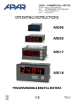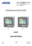
1
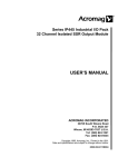
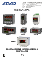
USER MANUAL
AR682
AR642
AR662
AR692
AR602
AR652
AR632
PROGRAMMABLE MICROPROCESSOR
CONTROLLERS
Version 1.5.4
2014.04.29
Thank you for choosing our product.
This manual will help you use your controller correctly, safely and to its full potential.
Read this manual carefully before installing and putting your controller to use.
In case of additional questions, please contact the technical advisor.
CONTENTS
1. SAFETY RULES .............................................................................................................................................. 3
2. INSTALLATION RECOMENDATION........................................................................................................... 3
3. GENERAL FEATURES OF CONTROLLERS ................................................................................................. 3
4. KIT................................................................................................................................................................... 4
5. TECHNICAL SPECIFICATION ...................................................................................................................... 4
6. DIMENSIONS AND INSTALLATION DATA................................................................................................ 6
7. DESCRIPTION OF TERMINAL STRIPS AND ELECTRICAL CONNECTIONS ........................................... 7
8. IMPORTANT TIPS – using the suppression systems .............................................................................. 8
9. DESCRIPTION OF BUTTONS AND SIGNAL LED INDICATORS .............................................................. 9
9.1. FUNCTION BUTTON AND BINARY INPUT ....................................................................................... 9
10. SETTING THE CONFIGURATION PARAMETERS .................................................................................. 10
11. QUICK ACCESS MENU ............................................................................................................................ 14
12. OUTPUTS CONFIGURATION ................................................................................................................. 14
12.1. CHANGING THE OUTPUTS SET VALUES ..................................................................................... 14
12.2. TYPES OF OUTPUT CHARACTERISTICS ....................................................................................... 15
12.3. ANALOGUE OUTPUT ..................................................................................................................... 16
12.4. PID CONTROL.................................................................................................................................. 16
12.5. AUTOMATIC SELECTION OF PID PARAMETERS ........................................................................ 17
12.6. ADJUSTMENT OF PID PARAMETERS ........................................................................................... 18
12.7. PROGRAMMABLE CHARACTERISTICS (RAMPING) ................................................................... 18
12.8. MANUAL AND REMOTE CONTROL OPTION .............................................................................. 19
13. ERRORS AND MESSAGES ....................................................................................................................... 19
14. CONNECTING TO THE PC AND AVAILABLE SOFTWARE ................................................................... 19
15. RS485 COMMUNICATION INTERFACE (acc. to EIA RS-485) ............................................................ 20
16. MODBUS–RTU SERIAL TRANSMISSION PROTOCOL (SLAVE) .......................................................... 21
17. NOTES ....................................................................................................................................................... 23
!
Please pay particular attention to fragments marked with this sign.
The manufacturer reserves its rights to modify the design and software of the device without deteriorating its technical parameters.
2
1. SAFETY RULES
!
read this manual carefully before starting to use the device;
to prevent the hazard of electric shock or equipment damage the mechanical and electrical installation should
be performed by qualified personnel;
before powering the device make sure all leads have been connected correctly;
disconnect the power supply before making any modifications of the leads configurations;
ensure correct operating conditions (supply voltage, temperature, humidity, see section 5).
2. INSTALLATION RECOMMENDATION
!
The controller has been designed to provide an adequate level of immunity to most disturbances which can
appear in industrial environments. In environments with unknown disturbance level it is recommended to use the
following preventive measures:
without proper line filters do not provide the power supply to the controller from the same lines which supply
large equipment;
use screened power supply, sensor and signal cables; the screen earthing shall be one-point type, located as
close to the device as possible;
avoid placing the measuring (signal) leads in direct vicinity of and parallel to power supply cables or lines;
it is recommended to twist the signal leads in pairs;
use identical leads for resistance sensors in 3-lead connection;
avoid proximity of remotely controlled devices, electromagnetic meters, large electrical loads, loads with phase
or group power control, and other devices generating large pulse disturbance;
provide earthing or neutralization to metal rails on which the rail-mounted devices are installed.
Before using the device, remove the screen protective film from LED display.
3. GENERAL FEATURES OF CONTROLLERS
control and supervision of temperature and other physical magnitudes (humidity, pressure, level, velocity, etc.)
converted to standard electrical signal (0/4÷20mA, 0÷10V, 0÷60mV, 0÷2.5kΩ);
1 multi-purpose measuring input (resistance thermometers, thermocouple, and analogue);
Programmable digital input and function button to change the controller operation mode:
start/stop regulation, manual mode for output, step change set value (daily/night), lock keypad;
2 or 3 ON-OFF outputs with the following control characteristics:
- output 1 (main): ON-OFF with hysteresis, PID, PID AUTOTUNING
- output 2, 3 (auxiliary/alarm): ON-OFF with hysteresis
0/4÷20mA or 0/2÷10V analogue outputs (control-continuous, retransmission);
possible conversion of input signals to the analogue output standard in the signal retransmission mode;
advanced function of PID parameters selection with fuzzy logic elements;
manual mode (open control loop) available to switching and analogue outputs allowing to set the input signal
value in the 0 ÷ 100% range, the ability to auto-activation for (input) sensor failure;
programmable programmable operating characteristics (process controller, ramping)
built-in 24Vdc power supply to supply field transmitters;
two-line LED display with brightness adjustment TOP display – measured value, BOTTOM– input 1_set value;
RS485 serial interface (galvanically isolated, MODBUS-RTU protocol);
programmable input type, range of indications (for analogue inputs), options of control, alarms, communication,
access, and other configuration parameters;
line resistance compensation for resistance and thermocouple cold junction compensation;
password-protected access to configuration parameters;
3
methods of parameters configuration:
- from the keypad on the controller front panel;
- via RS485 or AR955 programming device and ARSOFT-WZ1 freeware (Windows 2000/XP/Vista/7)
software and AR955 programming device which allows viewing the measured value and a quick configuration
of single or ready-to-use parameter sets previously saved in the computer to be reused, for example in other
controllers of the same type (configuration duplication);
board enclosure (IP65 front, IP54 - AR692), AR662 - enclosure for installation on the DIN 35 mm rail (IP20)
AR632 - IP65 industrial enclosure;
options (specify in the purchase order): 24Vac/dc power supply, SSR control outputs, 0/2÷10V analogue output,
and RS485 interface;
high accuracy, long-term stability and immunity to disturbance;
available accessories:
- AR955 programming device (with optional adapted for AR602 – version AR955/GP)
- RS485/USB converter
!
NOTE:
Before starting to use the controller read this manual and correctly perform the electrical, mechanical
installation and the parameter configuration.
4. KIT
controller with fastening holders to install in the board window;
user manual
warranty card
5. TECHNICAL SPECIFICATION
1 multi-purpose input (set using the 0: inP parameter)
Measuring range
- Pt100 (RTD, 3- or 2-lead)
-200 ÷ 850
°C
- Ni100 (RTD, 3- or 2-lead)
-50
÷ 170
°C
- Pt500 (RTD, 3- or 2-lead)
-200 ÷ 620
°C
- Pt1000 (RTD, 3- or 2-lead)
-200 ÷ 520
°C
- thermocouple J (Fe-CuNi)
-40
÷ 800
°C
- thermocouple K (NiCr-NiAl)
-40
÷ 1200
°C
- thermocouple S (PtRh 10-Pt)
-40
÷ 1600
°C
- thermocouple B (PtRh30PtRh6)
300
÷ 1800
°C
- thermocouple R (PtRh13-Pt)
-40
÷ 1600
°C
- thermocouple T (Cu-CuNi)
-25
÷ 350
°C
- thermocouple E (NiCr-CuNi)
-25
÷ 820
°C
- thermocouple N (NiCrSi-NiSi)
-35
÷ 1300
°C
- current
0/4
÷ 20
mA
- voltage (Rwe = 110 kΩ )
(Rwe = 50 Ω)
0
÷ 10
V
- voltage (Rwe > 2 M Ω)
0
÷ 60
mV
- resistance (3- or 2-lead)
0
÷ 2500
Ω
Response time (10 ÷ 90%)
0,25 ÷ 3 s (set using the 1: FiLt parameter)
Leads resistance (RTD, Ω)
Rd < 25 Ω (for each line)
4
400 μA (Pt100, Ni100), 200 μA (remaining)
Resistance input current (RTD, Ω)
Processing errors (at 25°C ambient temperature):
- basic
- dla RTD, mA, V, mV, Ω
0.1 % of measuring range ±1 digit
- for thermocouples
0.2 % of measuring range ±1 digit
- additional for thermocouples
<2 °C (cold ends temperature)
- additional caused by ambient temperature changes
< 0.003 % of input range /°C
Resolution of measured temperature
0.1 °C or 1 °C, programmable
Indication range (analog inputs resolution)
-1999 ÷ 9999, programmable
Decimal point position for analog inputs
0 ÷ 0,000, programmable
Binary inputs (contact or voltage <24V)
Bistable, active level: short-circuit or < 0.8V
Communication
interfaces
- RS485 (galvanically separated),
option
(RS485 and PRG, do not
use at the same time)
- PRG programming link
(no separation), standard
Switching outputs
- relay (P1, P2, P3),
standard (P3 unavailable to
AR602)
8A / 250Vac 1 main (SPDT), 2 additional (SPST-NO),
AR602, AR662: 5A / 250Vac (SPST-NO),
AR632: 1 main (SPDT) - 8A / 250Va, 2 additional (SPSTNO) - 5A / 250Vac, for resistive loads
- SSR (SSR1, SSR2, SSR3), option
(SSR3 unavailable to AR602)
transistor, type NPN OC, 10,5 ÷ 11V, internal resistance
440 Ω
AR632, AR692 – current sources about 22mA / 10V
- current 0/4 ÷ 20 mA (standard)
maximum resolution 1.4 μA (14 bit)
(3 or 2 for AR602, relay
type or SSR type)
Analogue outputs
- bitrate 2.4 ÷ 115.2 kb/s,
- format 8N1 (8 data bits, no parity bit, 1 stop bit)
- MODBUS-RTU protocol (SLAVE)
output load Ro < 350 Ω
(1 current or voltage,
- voltage 0/2 ÷ 10 V (option,
not separated from
instead of 0/4 ÷ 20 mA output)
the input)
- output basic error
7-segment LED display
(2 lines with 4 digits each, brightness
control)
Signalling
maximum resolution 0.7 mV (14 bit)
output load Io < 3.7 mA (Ro > 2.7kΩ)
< 0.1 % of output range
- top
red, height:
14 mm (AR652, AR632), 20mm (AR682), 9mm (AR642,
AR602), 10mm (AR662), 25mm (AR692)
- bottom
green, height:
10 mm (AR652, AR632), 14mm (AR682, AR692),
9mm (AR642), 7mm (AR602, AR662)
- relays active
LED’s, red
- messages and errors
LED display
Power supply (Usup) - 230Vac (standard)
85 ÷ 260 Vac/ 3VA
- 24Vac/dc (option)
20 ÷ 50 Vac/ 3VA, 22 ÷ 72 Vdc/ 3W
Power supply to field transmitters
24Vdc / 30mA
Rated operating conditions
0 ÷ 50°C, <90 %RH (non-condensing)
Working environment
air and neutral gases
Protection rating
AR632 - IP65, AR662 - IP20, remaining IP65 front (AR692 - IP54), IP20 of the connections side
Weight
~200g (AR652, AR642), ~280g (AR682), ~135g(AR602), ~160g (AR662), ~310g (AR692),
~320g (AR632)
immunity: acc. to PN-EN 61000-6-2:2002(U)
Electromagnetic compatibility (EMC)
emission: acc. to PN-EN 61000-6-4:2002(U)
5
6. DIMENSIONS AND INSTALLATION DATA
a) AR652, AR642, AR602
Enclosure type
Material
Enclosure dimensions
(W x H x D)
Window in the board
(W x H)
Fastening
Leads cross sections (for
separable connections)
board-type, Incabox XT L57
self-extinguishing polycarbonate NORYL
94V-0
AR652: 96x48x79mm, AR642:
48x96x79mm AR602: 48x48x79mm
AR652: 92 x 46 mm, AR642: 46x92mm,
AR602 : 46 x 46 mm
holders on the enclosure side
2.5mm2 (power and binary outputs),
1.5mm2 (remaining)
b) AR682
Enclosure type
Material
Enclosure dimensions
Window in the board
Fastening
Leads cross sections (for
separable connections)
board-type, Incabox XT L57
self-extinguishing polycarbonate NORYL
94V-0
96 x 96 x 79mm (W x H x D)
92 x 89 mm (W x H )
holders on the enclosure side
2.5mm2 (power and binary outputs),
1.5mm2 (remaining)
c) AR662
Enclosure type
Material
Enclosure dimensions
Fastening
Leads cross sections (for
separable connections)
rail, Modulbox 3MH53
ABS/PC
53 x 90 x 62 mm (W x H x D)
on the TS35 rail (DIN EN 50022-35)
2.5mm2 (power and binary outputs),
1.5mm2 (remaining)
d) AR692
Enclosure type
Material
Enclosure dimensions
Window in the board
Protective cover IP54
Fastening
Leads cross sections (for
separable connections)
board-type, Incabox L57
self-extinguishing NORYL 94V-0
144 x 72 x 72 mm (W x H x D)
138 x 67 mm (W x H)
AR967 (option)
holders on the enclosure side
2.5mm2 (power and binary outputs),
1.5mm2 (remaining)
d) AR632
Enclosure type
Material
Enclosure dimensions
Fastening
Leads cross sections (for
separable connections)
industrial IP65, Gainta G2104
polycarbonate
120 x 80 x 55 mm (W x H x D)
4 dia 4.3 mm holes, spacing 108x50 mm,
accessible after removing the front cover
2.5mm2 (power and binary outputs),
1.5mm2 (remaining)
6
120
80
7. DESCRIPTION OF TERMINAL STRIPS AND ELECTRICAL CONNECTIONS
Table 7. Number and designation of terminals
Terminals
Description
1-2-3
Pt100, Ni100, Pt500, Pt1000 resistance input, (2- and 3-lead)
2-3
TC (J, K, S, B, R, T, E, N) thermocouple input and 0÷60mV voltage input
3-5
0/4÷20mA current input
4-5
0÷10V voltage input
6
+24V input (in relation 5-GND) of the built-in power supply for field transmitters
5-7
binary input (contact or <24V voltage)
5-8
analogue current output (0/4÷20mA) or voltage (0/2÷10V)
PRG
programming connection for the programming device (only AR955)
9-10 (7-8 for AR602)
RS485 serial interface (MODBUS-RTU protocol), in AR602 the RS485 interface rules out
the analogue output and binary input (acc. to the purchase order code)
12-13
230Vac or 24Vac/dc power supply input
14-15-16
P1 or SSR1 relay output (14-15), for AR602 P2 or SSR2 output: 14-15
17-18
P2 or SSR2 relay output, for AR602 P1 or SSR1 output
19-20 (except AR602) P3 or SSR3 relay output
a.1) AR642, AR652, AR682 – terminals description Table 7
a.2) AR602 - terminals description Table 7
a.3) AR692, AR632 – terminals description Table 7 (in AR632 PRG socket is accessible on the display board)
!
NOTE:
To install the cabling in the AR632, follow the instructions given below:
− remove 4 bolts in the front panel and remove the panel;
− fasten the controller to the base using 4 screws and fastening holes;
− remove one bolt on the display board and carefully pull out the board from its seats;
7
−
−
−
−
−
now you have access to terminals to connect the signal, power supply, and relay outputs leads;
insert the leads to the controller through cable glands;
after connecting, reassemble the controller in reverse order;
to get the IP65 rating, precisely tighten the glands’ nuts and the enclosure cover;
to prevent mechanical and electrostatic damage, exercise particular caution when handling the display board.
a.4) AR662 – terminals description Table 7
!
NOTE:
To connect to the computer via the PRG socket, use only the AR955 programming device (with optional adapter
for AR602). Connection using the simple USB cable can damage the controller.
b) connecting 2- and 3-lead transmitter (Iout - current, Uout – output voltage)
8. IMPORTANT TIPS – using the suppression systems
!
If an inductive load (e.g. contactor coil, transformer) is connected to the relay contacts, overvoltage and arc
appear often during opening as a result of discharge of energy accumulated in the inductance. Particularly
harmful effects of such overvoltage include reduced life of contactors and relays, destruction of semiconductors
(diodes, thyristors, triacs), damage or disturbance of control and measurement systems,
emission of electromagnetic fields causing interference with local devices. To avoid such
effects, the overvoltage must be reduced to a safe level. The easiest method is connecting a
suitable suppression module directly to the inductive load terminals. Generally, a suitable
type of suppression system should be selected for each inductive load. Modern contactors usually have factoryinstalled suitable suppression systems. If they do not, a contactor with a built-in suppression system should be
bought. Temporarily, you can shunt the load using the RC system, e.g. R=47Ω/1W and C=22nF/630V. Connect the
suppression system to the inductive load terminals. This will limit burning of the relays contacts in the controller
and reduce the probability that they will get stuck.
8
9. DESCRIPTION OF BUTTONS AND SIGNAL LED INDICATORS
Description the front
elevation for
example AR652
7-segment LED display
programming buttons
LED indicators
a) functions of buttons in the measurement display mode
Button
Description [and designation in the manual]
[UP] or [DOWN]: change set value for input 1 (parameter 9:
output 1 is in manual mode (see sections 10 and 12.8)
or 26:
when
[SET] :
- go to the quick access menu (see section 11)
[UP] and [DOWN] (simultaneously): go to the parameter configuration menu (if pressed
for longer than 1 s). If the parameter 33: PPro = on (password protection on), enter the
access password, section 10)
[F] (unavailable in AR602): start the function programmed by parameter 34: Func (if
pressed for longer than 1 s, sections 9.1 and 10)
b) functions of buttons in the parameter configuration menu and quick access menu (sections 10 and 11)
Button
Description [and designation in the manual]
[SET] :
- edit current parameter (the value in the bottom display is flashing)
- confirm and save the edited parameter
[UP] or [DOWN]:
- go to the next parameter
- change the value of current parameter
[UP] and [DOWN] (simultaneously):
- cancel the modifications of edited value (flashing stops)
- return to the measurement display mode (if held for > 0.5s)
c) functions of signal LED indicators
LED indicators [designation]
[1] [2] [3]
Description
inputs P1/SSR1, P2/SSR2, P3/SSR3 are on
9.1. FUNCTION BUTTON AND BINARY INPUT
Function button [F] (unavailable in AR602) and binary input BIN perform the same function programmable by
parameter 34: Func (section 10). The binary input cooperates with the bistable signal, i.e. the received signal
(voltage or switch) must be of durable character (on/off type). In addition, the [F] is inactive when the BIN is active
(short-circuit or voltage <0.8V). Starting and stopping of the function is signalled by relevant message on the
bottom display (described in Table 9.1).
9
Table 9.1. Available functions of button [F] and input BIN
Source
Description (depending on the value of parameter 34: Func )
Message
-
Func = nonE button [F] and input BIN inactive (factory setting)
Func = Set3 discrete change of set value for P1/SSR1 output
(day = parameter 9: Set1 /night = 16: Set3 , Table 10)
or
Set1 / Set3
Func = bLoc keypad locked (except button [F])
bLoc / boFF
Func = hAn1 unconditional manual mode for output P1/SSR1 (section 12.8)
hAnd / hoFF
Func = hAn2 unconditional manual mode for output P2/SSR2
hAnd / hoFF
Func = hAn3 unconditional manual mode for output P3/SSR3
hAnd / hoFF
Func = hAnA unconditional manual mode for analogue output
hAnd / hoFF
Func = StSP control start/stop (applies to all outputs)
Star / StoP
10. SETTING THE CONFIGURATION PARAMETERS
All configuration parameters are stored in a non-volatile internal memory. When the controller is switched on for
the first time, an error message may appear indicating that there is no sensor or that the sensor is different than
programmed. Connect the right sensor or perform the configuration programming.
There are two methods of parameter configuration:
1. Using the keypad on the front panel:
−
from the measurement display mode go to the configuration menu (simultaneously press [UP] and
[DOWN] buttons for longer than 1 s). If the parameter 33: PPro = on (password protection on), the display
will show the message CodE and then 0000 with the first digit flashing. Use the [UP] or [DOWN] buttons
to enter the access password (default parameter 32: PASS = 1111 ). Use the [SET] button to go to
successive positions and to approve the code;
− after entering the configuration menu (with the ConF message) the main display shows the mnemonic
name of the parameter (inP <-> FiLt <-> dot <->, etc.), and the bottom one its value;
− use the [UP] button to go to the next parameter, and the [DOWN] button to return to the previous
parameter (the list of all parameters is given in table 10);
− to change the value of selected parameter, briefly press [SET] (flashing in the edit mode);
− change the value of parameter using [UP] or [DOWN] buttons;
− confirm new value by pressing [SET] or cancel: [UP] and [DOWN] (press simultaneously briefly) and the
display will again show the parameter name;
− to exit the configuration menu: press [UP] and [DOWN] simultaneously for a longer time. The controller will
exit the configuration menu automatically after about 2 min. of inactivity.
2. Via the RS485 port or PRG (AR955 programming device) and the ARSOFT-WZ1 application (section 14):
- connect the controller to the computer, start and configure the ARSOFT-WZ1 application
- when the connection is made, the program window will show the current measured value
- setting and viewing of parameters is possible in the parameter configuration window
- press the Accept Changes button to approve new values
- current configuration can be saved in a file or set using the values read from the file
- file with ready configuration can also be created using the ARSOFT-WZ4 application (section 14)
10
!
NOTE:
- before disconnecting the controller from the computer press the Disconnect Device button (ARSOFT-WZ1)
- if the program does not respond:
in Program Options check the port configuration and the MODBUS device address
make sure that the serial port drivers in the computer have been correctly installed for the
RS485 converter or the AR955 programming device
disconnect the RS485 converter or the AR955 programming device for a few seconds and then
reconnect
restart your computer
If the indications are different that actual input signal value, you can tune the zero and sensitivity to a given
sensor: parameters 38: cALo (zero) and 39: cALG (sensitivity).
To restore factory settings: on powering up press [UP] and [DOWN] until the password menu appears (CodE), and
then enter the 0112 code. Alternatively, use the file with default configuration in the ARSOFT-WZ1 application.
!
NOTE:
Do not configure the device from the keypad and via the serial interface (RS485 or AR955) at the same time.
Table 10. List of all configuration parameters
Parameter
0: inP
type of measuring input
1: FiLt filtration (1)
2: dot
dot position/resolution
Parameter range and description
Pt
thermal resistant sensor (RTD) Pt100 (-200 ÷ 850°C)
ni
thermal resistant sensor (RTD) Ni100 (-50 ÷ 170°C)
Pt5
thermal resistant sensor (RTD) Pt500 (-200 ÷ 620°C)
Pt10
thermal resistant sensor (RTD) Pt1000 (-200 ÷ 520°C)
tc-J
thermoelectric sensor (thermocouple) J (-40 ÷ 800°C)
tc-K
thermoelectric sensor (thermocouple) K (-40 ÷ 1200°C)
tc-S
thermoelectric sensor (thermocouple) S (-40 ÷ 1600°C)
tc-b
thermoelectric sensor (thermocouple) B (300÷ 1800°C)
tc-r
thermoelectric sensor (thermocouple) R (-40 ÷ 1600°C)
tc-t
thermoelectric sensor (thermocouple) T (-25 ÷ 350°C)
tc-E
thermoelectric sensor (thermocouple) E (-25 ÷ 820°C)
tc-n
thermoelectric sensor (thermocouple) N (-35÷ 1300°C)
4-20
4 ÷ 20 mA current signal
0-20
0 ÷ 20 mA current signal
0-10
0 ÷ 10 V voltage signal
0-60
0 ÷ 60 mV voltage signal
rES
0 ÷ 2500 Ω resistance signal
1 ÷ 20
digital filtration of measurements (response time)
0
no dot (2) or 1°C resolution for temperature
1
0.0 (2) or 0.1°C resolution for temperature
2
0.00 (2)
3
(2)
11
Default
settings
Pt
5
1
(0.1°C)
3: Lo1 low limit 1 or
bottom of indications
range (2)
/99.9 ÷ 1800
low settings limit for the set value 9: Set1
/999 ÷ 9999
indications for 0/4mA, 0V, 0Ω – beginning of input scale (2)
4: Hi1 high limit 1 or top of /99.9 ÷ 1800
indications range (2)
/999 ÷ 9999
high settings limit for the set value 9: Set1
indications for 20mA, 10V, 60mV, 2500Ω – end of input scale (2)
5: Lo2
low limit 2
/99.9 ÷ 1800
low settings limit for the set value 13: Set2
3: Lo1 ÷ 4: Hi1
low settings limit for 9: Set1 and 13: Set2 (2)
6: Hi2
high limit 2
/99.9 ÷ 1800
high settings limit for the set value 13: Set2
3: Lo1 ÷ 4: Hi1
low settings limit for 9: Set1 and 13: Set2 (2)
/99.9 °C
850.0 °C
/99.9 °C
850.0 °C
CONFIGURATION OF MAIN OUTPUT (P1/SSR1) - section 12 (12.2)
7: Fto1 emergency state of output state when the sensor (signal) absent or damaged: noCh = no change,
output 1 (3)
oFF,or on , hAnd = manual mode with set value = 26: HSEt (section.12.8)
8: out1 function of output 1 oFF, hAnd = manual mode (section.12.8), inv= heating, dir = cooling
9: SEt1 set value 1
for output 1, changes in the range 3: Lo1 ÷ 4: Hi1 or 5: Lo2 ÷ 6: Hi2 (2)
10: H1 hysteresis of output
1 or PID tuning zone
hysteresis or PID tuning insensitiveness zone in the Auto mode, section 12.5,
0.0 ÷ 999.9 °C or 0 ÷ 9999 units (2)
noCh
inv
100.0 °C
1.0 °C
CONFIGURATION OF AUXILIARY OUTPUTS (P2/SSR2 and P3/SSR3) - section 12
11: Fto2 emergency state
of output 2 (3)
output state when the sensor (signal) absent or damaged: noCh = no change,
oFF,or on , hAnd = manual mode with set value = 26: HSEt (section.12.8)
noCh
12: out2
function of output 2
(section 12.2)
oFF , hAnd = manual mode, inv= heating, dir = cooling,
bAonor bAoF= band 2* SEt2 around SEt1,
dEoFor dEon= deviation from SEt1,
rEon , rEoF , rEP3 = controlled by the ramping controller (ramping), sec. 12.7
inv
13: SEt2 set value 2
for output 1, changes in the range 5: Lo2÷ 6: Hi2 (2)
14: H2 hysteresis of output 2
0.0 ÷ 999.9 °C or 0 ÷ 9999 units (2)
15: out3
function of output 3
(section 12.2)
oFF , hAnd = manual mode, inv= heating, dir = cooling
bAon or bAoF= band 2* SEt3 around SEt1,
dEoF or dEon= deviation from SEt1,
rEon , rEoF , rEP3 = controlled by the ramping controller (ramping), sec. 12.7
16: SEt3 set value 3
for output 3, /99.9 ÷ 1800 or /999 ÷ 9999 units (2)
100.0 °C
1.0 °C
oFF
100.0 °C
CONFIGURATION OF ANALOGUE OUTPUT (section 12.3)
17:
type
analogue output
18: outA analogue output
function
depending on the purchase order code: 0-20 or 4-20 mA for current output,
0-10 or 2-10 V for voltage output
oFF, hAnd = manual mode, rEtr = measurement retransmission, cont =
control output, detailed description in section 12.3
19: A-Lo low indication for beginning of measurement scale – for the 0/4mA or 0/2V output signals
(parameter active only for the measurement retransmission when 18: outA = rEtr)
retransmission
20: A-Hi high indication
for retransmission
End of measurement scale – for the 20mA or 10V output signals (parameter
active only for the measurement retransmission when 18: outA = rEtr)
0-20 mA
(0-10 V)
oFF
0.0 °C
100.0 °C
CONFIGURATION OF PID ALGORITHM AND MANUAL MODE
21: tunE type of PID tuning
oFF, Auto = automatic selection (continuous tuning), StEP = step method
(quick), oSct = oscillation method (slower), section 12.5
22: Pb PID proportionality
range
0.0 ÷ 1800 or 0 ÷ 9999 units (2), 0 - discontinues PID action; description of
PID algorithm and related subjects in sections 12.4 ÷ 12.6
12
oFF
0.0 °C
23: ti PID integration time
constant
0 ÷ 3600 sek.
PID algorithm integration time,
0 switches off the PID algorithm’s integration module
0s
24: td PID differentiation
time constant
0 ÷ 999 sek.
PID algorithm differentiation time,
0 switches off the PID algorithm’s differentiation module
0s
25: tc pulsing period
3 ÷ 360 sek.
for binary outputs (1, 2, 3) in manual mode and PID
5s
control value for outputs in manual mode, applies for all
26: HSEt manual mode set 0 ÷ 100 %
1% increments outputs (1, 2, 3 and analogue), section 12.8
value
50.0 %
CONFIGURATION OF PROCESS CONTROLLER (programmable characteristic curve, ramping, section 12.7)
27: rAMP process controller oFF , MAnv = manual start, Avto = start after each powering up and
mode (4)
adjustment (with the [F] button or BIN input, when 34: Func = StSP)
oFF
28: rAr stage 1 gradient
for stage Pr-1 , 0.1 ÷ 30.0 °C/min or 1 ÷ 300 of units/min (2)
0.1 °C
29: th1 stage 2 duration
0 ÷ 8640 min. duration of stage Pr-2 , 0 stops the Pr-2 stage permanently
30 min.
30: th2 stage 4 duration
0 ÷ 8640 min. duration of stage Pr-4 , 0 stops the Pr-4 permanently
30 min.
ACCESS AND COMMUNICATION OPTIONS, OTHER CONFIGURATION PARAMETERS
31: bSEt blocked changes
in SEt1 , SEt2
oFF = changes not blocked, SEt1 = changes blocked in parameter 9: SEt1,
SEt2 = changes blocked in 13: SEt2, both = changes blocked
simultaneously in 9: SEt1 and 13: SEt2
oFF
32: PASS access password
0000 ÷ 9999
password to get access to parameter configuration
1111
33: PPro passwordprotected configuration
oFF
entry to the configuration menu is not password-protected
on
entry to the configuration menu is password-protected
nonE
button [F] and input BIN inactive
Set3
switch over of set value (day/night) for output 1
bLoc
keypad locked (except the [F] button)
hAn1
unconditional manual mode for output 1 (P1/SSR1)
hAn2
unconditional manual mode for output 2 (P2/SSR2)
hAn3
unconditional manual mode for output 3 (P3/SSR3)
hAnA
unconditional manual mode for analogue output
StSP
control start/stop (applies to all outputs)
35: briG display
brightness
20 ÷ 100 %
display brightness, in 20% increments
36: Addr MODBUS-RTU
address
1 ÷ 247
individual device address in the RS485 network (section 16)
2.4 kbit/s
4.8 kbit/s
9.6 kbit/s
38.4 kbit/s
57.6 kbit/s
115.2 kbit/s
34: Func
[F] button
and BIN input function
(section 9.1)
37: br
baudrate for RS485
and PRG port
nonE
100 %
19.2 kbit/s
38: cALo zero calibration
null bias for measurements: -50.0 ÷ 50.0 °C or -500 ÷ 500 of units (2)
39: cALG gain
85.0 ÷ 115.0 % slope calibration (sensitivity) for measurements
Notes:
on
1
19.2 kbit/s
(1) - for FiLt = 1 the response time is 0.25s, for FiLt = 20 at least 3s. Higher level of filtration
means a “smoother” measured value and longer response time recommended for turbulent
measurements (e.g. water temperature in a boiler)
(2) - applies to analogue inputs (mA, V, mV, Ω ), when 3: Lo1 is greater than 4: Hi1, we get
an inverse curve (negative slope)
(3) - parameter defines also the output status outside the measuring range
(4) - process controller precludes PID auto-tuning and PID control
13
0.0 °C
100.0 %
11. QUICK ACCESS MENU
The measurement mode (measured value display mode) provides an opportunity of an immediate access to some
configuration parameters and functions without entering the password. This opportunity is called quick access
and is available after pressing the [SET] button. The selection and editing of the parameter is analogous to the
description in section 10.
Table 11. List of all parameters available in the quick configuration menu
Element
Description
SEt1
set value 1(parameter 9: SEt1), optional element – unavailable when parameter 8: out1 = hAnd, changes
are blocked during the selection of PID (tuning) parameters (section 12.5), in the process controller mode
(section 12.7), and change of set value 1 to SET3 (section 9.1)
SEt2
set value 2 (13: SEt2), optional element – unavailable when parameter 12: out2 = oFF or hAnd
SEt3
set value 3 (16: SEt3), optional element – unavailable when parameter 15: out3 = oFF or hAnd
t-St
PID tuning start/stop (section 12.5), optional element – unavailable when parameter 21: tunE = oFF
P-St
process controller start/stop (section 12.7), optional element – unavailable when parameter 27: rAMP =
oFF
HSEt
set value for manual mode (26: HSEt), optional element – available for outputs in manual mode
12. OUTPUTS CONFIGURATION
Programmable architecture of the controller allows it to be used in many fields and applications. Before using the
device, its parameters need to be customized (section 10). The detailed description of outputs configuration is
given in sections 12.1 ÷ 12.8. The default factory configuration is as follows: outputs 1 and 2 are in the ON-OFF
mode with hysteresis, output 3 and analogue outputs are off (Table 10, Default settings column).
12.1. CHANGING THE OUTPUTS SET VALUES
In the measurement mode the top display shows the measured value and the bottom one the output 1 set value
(parameter 9: SEt1 or 26: HSEt when the controller is in manual mode). The easiest way to change the set value is
to use the [UP] or [DOWN] buttons. Quick access menu (section 11) can be used for other outputs. As an
alternative, the modification of each set value is available in the parameter configuration mode, using methods
described in section 10.
14
12.2. TYPES OF OUTPUT CHARACTERISTICS
Type of operation of each output is programmed using the parameters 8: out1, 12: out2, and 15: out3,
section 10, Table 10.
a) basic outputs characteristics curves
b) additional outputs characteristics curves (only for outputs 2 and 3)
NOTE: * H3 is constant and equals 0.2°C (2 units), not subject to configuration
15
12.3. ANALOGUE OUTPUT
The output signal standard is determined by parameter 17: AtYP (section 10, Table 10). The analogue output can
be used in one of the following modes: measurement retransmission (parameter 18: outA = rEtr), manual (18:
outA = hAnd) and as an automatic control output (18: outA = cont).
In the measurement retransmission mode, the output signal is proportional to the signal measured in the range
set by parameters 19: A-Lo and 20: A-Hi (e.g. 0mA for the measured value 0°C when A-Lo = 0°C, 20mA for 100°C
when
= 100°C, and correspondingly 10mA for the half range, i.e. 50°C ). In other words, in the retransmission
mode the output converts the input signal to the output signal (in the A-Lo ÷ A-Hi range). Manual mode (section
12.8) allows a smooth conversion of the input signal into the output signal in the 0 ÷ 100% range with 1%
increment and initial value equal to the last value in automatic mode (measurement retransmission or control).
In the automatic control mode, the parameters and functions are identical as for output 1 (applicable are 7: Fto1 ,
8: ovt1 , 9: SEt1 , 10: H1 , algorithm and PID tuning parameters and the process control).
In the control mode, the analogue signal variation range is continuous only for the PID algorithm (within the
proportionality range, section 12.4), in case of the ON-OFF mode with hysteresis the output has the extreme
values (low or high value, e.g. 0mA or 20mA), with no intermediate values.
12.4. PID CONTROL
The PID algorithm gives smaller control errors (e.g. temperature) than the
ON-OFF method with hysteresis. However, this algorithm requires the
selection of typical parameters for a given controlled facility (e.g. a
furnace). To simplify the use, the controller is equipped with advanced
functions of selecting the PID parameters which are described in section
12.5. In addition, it is always possible to correct the settings manually
(section 12.6).
The controller operates in the PID mode when the proportionality range
(parameter 22: Pb) is non-zero. Relation between the proportionality
range Pb and the set value SEt1 is shown in figures 12.4 a) and b). The
impact of the integration and differentiation is defined by the
parameters 23:
and 24: . The parameter 25:
determines the
pulsing period for output 1 (P1/SSR1). When the PID algorithm is effected
by the 0/4÷20mA or 0/2÷10V analogue output, the parameter
is
irrelevant. In that case, the output signal can have any intermediate value
from the entire output variability range.
Regardless of the output type, the output status is always adjusted
every 1s.
The principle of operation of the P type (proportional) control for output
1 is shown in figures d), e), for analogue output in figure c).
Fig. 12.4. PID control - principle of operation:
a) Relation between the proportionality range Pb and the set value
SEt1 for heating (ovt1 = inv)
b) Relation between the proportionality range Pb and the set value
SEt1 for cooling (ovt1 = dir)
c) status of analogue output 0/4÷20 mA or 0/2÷10V
d) filling ratio for output 1 (P1/SSR1)
e) status of output 1 for measured value within the proportionality range
16
12.5. AUTOMATIC SELECTION OF PID PARAMETERS
The first step to use the function of PID parameters selection is to choose the type of tuning (parameter 21: tunE,
section 10). The tuning will start automatically with start of control (after powering up, and also by pressing the
button [F], or by binary input BIN when parameter 34: Func = StSP, section 9.1). in addition, the tuning can be
stopped (oFF), and then restarted (on) at any time by using the function t-St available in the quick access menu
(section 11). When the tuning is in progress (i.e. when the display alternately shows the set value and the tvnE
message) the set value should not be changed (9: Set1 or 16: SEt3 when 34: Func = SEt3).
Value of parameter 21: tvnE determines the method of selecting the PID parameters:
a) 21: tunE = Auto - automatic selection – the controller continuously checks if there are conditions to start the
tuning and tests the facility to find a suitable method. The algorithm incessantly enforces the PID mode
operation. The necessary condition to initiate the PID parameters selection is the measured value being out of
the insensitiveness zone which is defined as the sum of parameter 22: Pb and 10: H1 in relation to set value 9:
Set1, as in figure 12.5.
Fig.12.5. Insensitiveness zone for
heating (8: ovt1 = inv) and
cooling (8: ovt1 = dir)
To avoid an unnecessary start of tuning, which may delay the process, it is recommended to set the H1 relatively
high, at least at 10÷30% of the process variability range (e.g. measured temperature variability range). The
facility testing with temporary output off and the tvnE message takes place also in the insensitiveness zone if
rapid changes of measured or set value are detected.
The method of parameters selection depends on the initial conditions. The fast step method will be used in case
of stabilized controlled value, otherwise the slower oscillation method will be applied.
The automatic selection ensures optimum PID parameters for current conditions in the facility, without the
user’s intervention. It is recommended for variable value control (disturbance of set conditions during operation
by modification of e.g. the set value or the furnace batch).
b) 21: tunE = StEP – selection of parameters in the step stage (response to step function). While determining the
characteristics of the object, the algorithm does not cause an additional delay in reaching the set value. This
method is dedicated to facilities with stabilized initial controlled value (e.g. temperature in a cold furnace). In
order not to disturb the stabilized initial conditions, before starting the autotuning, turn off the actuator’s (e.g.
the heater) power supply using an external switch, or use the control start/stop function [F] button or BIN
input). Turn on the power supply again immediately after the autotuning starts, during the output activation
delay phase. If the power supply is turned on later, the facility analysis will be incorrect and consequently the
PID parameters will not be selected correctly.
c) 21: tunE = oSct – selection of parameters using the oscillation method. The algorithm involves the
measurement of the oscillation amplitude and period at a slightly lower level for heating or a slightly higher
level for cooling than the set value in order to eliminate the danger that the target value will be exceeded
during the facility test stage. While determining the characteristics of the object, the algorithm causes an
additional delay in reaching the set value. This method is dedicated to facilities with unstable initial controlled
value (e.g. temperature in a hot furnace).
The algorithms from b and c comprise the following stages:
output activation delay (about 15s) – time to power up the actuator (heating/cooling power, fan, etc.);
determination of the facility characteristic curve;
determination and saving in the controller’s non-volatile memory of parameters: 22: Pb , 23: ti , 24: td
and 25: tc
activation of control with new PID settings.
17
The program can discontinue the autotuning b or c (with the Errt message) if the conditions for correct
algorithm operation are not met:
initial value is higher than the set value for heating or lower for cooling;
maximum autotuning duration (4 hours) has been exceeded;
process value changes too quickly or too slowly.
It is recommended to perform the autotuning b or c after a significant change of the SEt1 threshold or the
controlled facility parameters (e.g. heating/cooling power, charge, initial temperature, etc.).
12.6. ADJUSTMENT OF PID PARAMETERS
The autotuning function correctly selects the PID control parameters for most processes, but sometimes the
parameters need adjustment. Due to a strong interdependence of these parameters, adjust only one of them and
observe the impact on the process:
a) oscillation around the threshold – increase the proportionality range 22: Pb, increase integration time 23: ti,
decrease differentiation time 24: td, (possibly reduce the output 1 pulsing time by half, parameter 25: tc);
b) slow response - reduce the proportionality range Pb, differentiation time td and integration time ti;
c)
overshoot - increase the proportionality range Pb, differentiation time
and integration time ti
d) instability – increase the integration time ti.
12.7. PROGRAMMABLE CHARACTERISTICS (RAMPING)
Setting of parameter 27: rAMP (see section 10, Table 10) to MAnv or Auto allows to program the device as a 4step process controller, implemented by output 1, according to the diagram in presented fig. 12.7. This mode of
operation can be started manually at any time
(when parameter 27: rAMp = MAnv or Avto) and
automatically (rAMp = Avto) when the control
process begins (after powering up, and also using
the [F] button or BIN binary input when parameter
34: Func = StSP, section 9.1). To manually turn the
process controller on (on) or off (oFF)use the P-St
function available in the quick access menu
(section 11).
time
F
Fig.12.7. 4-step process controller operation diagram
Successive process stages are signalled by the messages displayed alternately with the set value (Set1 or Set2):
- Pr-1 - stage 1 – reaching the value of threshold 9: Set1 with the set gradient (28: rAr)) - ramping
- Pr-2 - stage 2 – implementation of the 1st hold time 29:
at the Set1 level (with hysteresis 10: H1),
the value of parameter th1 = 0 keeps permanently the stage Pr-2
- Pr-3 - stage 3 – reaching the value of threshold 13: Set2 at full power
- Pr-4 - stage 4 - implementation of the 2nd hold time 30: th2 at the Set2 (with hysteresis 14: H2 )
the value of parameter th2 = 0 keeps permanently the stage Pr-4
- End - end of process (output 1 permanently off)
In addition, it is possible to assign the output 2 or 3 to the process when parameter 12: out2 or 15: out3 equals:
rEon - output on after process end (off during the process)
rEoF - output off after process end (on during the process)
rEP3 - output on for stages Pr-3 and Pr-4
Operation in the process control mode precludes the PID autotuning and PID adjustment.
18
12.8. MANUAL AND REMOTE CONTROL OPTION
The manual mode allows to set the output signal over its whole range (0 ÷ 100% ), and consequently the enables
the open control loop operation (no automatic relationship between the measured value and the output signal).
The manual mode is available independently for each controller output and is programmable by the parameters
8: out1, 12: out2,15: out3 and 18: outA section 10, Table 10. In addition, output can be configured for a quick
(unconditional) manual mode controlled by:
- the function button [F] or binary input BIN, by suitably programming the parameter 34: Func (section 9.1),
- sensor measuring errors (exceeding the range or failure), when 7: Fto1 or 11: Fto2 is equal to hAnd
In case of switching outputs (1, 2, 3), the change of output signal involves setting the filling ratio (using the
parameter 26: HSEt) with pulsing period defined by parameter 25: tc The manual mode set value 26: HSEt = 0
means that the output is permanently off, value 100 means it is permanently on. This value can be set using the
[UP] and [DOWN] buttons (only for output 1, section 12.1) or the quick access menu (section 11), and alternatively
in the parameter configuration mode (from keypad or remotely via the RS485 serial port or PRG, sections 10, 14 ÷
16 ).
13. ERRORS AND MESSAGES
a) measuring errors:
Code
Possible errors
^^^^
____
- below (____) or above (^^^^) the sensor measuring range
- sensor damage
- other sensor than set in the configuration (section 10, parameter 0: inP)
b) messages and instantaneous errors (single and cyclical):
Code
Message
CodE
entering access password to configuration parameters, section 10
Err
wrong access password
ConF
parameter configuration menu
tunE
PID autotuning in progress, section 12.5
Errt
autotuning error, section 12.5, to delete error simultaneously press [UP] and [DOWN]
StAr / StoP
control start/stop, section 9.1
SEt1 / SEt3
switch over of set value (day/night) for output 1, section 9.1
bLoc / boFF
keypad lock on/off, section 9.1
hAnd / hoFF
unconditional manual mode on/off, section 9.1
Pr-1 ÷ Pr-4 , End
process control function (ramping), section 12.7
SAUE
save parameter values (section 10)
14. CONNECTING TO THE PC AND AVAILABLE SOFTWARE
Connecting the controller to the PC can be useful (or necessary) in the following situations:
−
remote monitoring and recording of current measurement data and process control (outputs status);
−
quick configuration of parameters, including copying the settings to other controllers of the same type.
In order to establish a long range communication, set up the connection in the RS485 standard with port available in the
computer (directly or by means of the RS485 converter), according to the description in section 15.
19
In addition, the controllers as a standard are equipped with PRG ports which allow to connect to the PC via the AR955
programming device (without galvanic isolation, cable length 1.2m). To use both the programming device and the RS485
port, the supplied serial port drivers must be installed on the computer.
The communication with the device is based on the protocol compatible with MODBUS-RTU (section 16).
The following applications are available (on CD in the kit with the AR955 programming device, or for downloading
from www.apar.pl – Download tag – for Windows 2000/XP/Vista/7/8):
Name
Application
−
−
ARSOFT-WZ1
(free)
−
−
ARSOFT-WZ4
(free)
ARSOFT-WZ2
(paid)
−
−
−
−
display current measuring data from connected device
configure the type of measuring input, range of indications, control options, alarms,
displaying, communication, access, etc. (section 10)
create a cfg file on the disc with current parameters configuration to reuse (configuration
duplication)
software requires communication with the controller via the RS485 or PRG (AR955)
create a .cfg configuration file on the disc for later controller programming via the RS485
interface or AR955 and ARSOFT-WZ1 programming device
software does not require communication with the controller
display current measuring data from maximum 30 channels simultaneously (only the
APAR devices)
software requires communication with the controller via the RS485 or PRG (AR955)
The detailed descriptions of these applications are included in the installation folders.
!
NOTE:
Before making the connection, make sure that the controller’s MODBUS address (parameter 36: Addr) and the
baudrate (37: br ) are identical to the settings of computer program. In addition, set in the program options the
number of the COM serial port (for the RS485 converter or AR955 programming device it is the number given by
the operating system during installation of the drivers).
15. RS485 COMMUNICATION INTERFACE (acc. to EIA RS-485)
Length of the RS485 cable – max. 1km Max. number of devices
in the RS485 line: 30. To increase the number of devices use
RS485/RS485 amplifiers. Termination resistors when MASTER
is at the beginning of the line (see fig. above):
- at the beginning of the line: 2 x 820Ω to frame and to +5V of the MASTER and 150Ω between lines,
- at the end of the line: 150Ω between lines.
Termination resistors when MASTER is in the middle of the line:
- at the converter: 2 x 820Ω to frame and to +5V of the converter,
- at both ends of the line: 150Ω between lines.
Devices from different manufacturers forming a network 485 (eg converters RS485/USB) may have a built-in
termination resistors, and then there is no need for external components.
20
16. MODBUS–RTU SERIAL TRANSMISSION PROTOCOL (SLAVE)
Format
Available function
: 8 bits, 1 stop bit, no parity bit
: READ - 3 or 4, WRITE - 6
Table 16.1. Claim frame format for the READ function (frame length – 8 bytes):
device
address
function
4 or 3
register address to be
read: 0 ÷ 56 (0x0038)
number of registers to be
read:
1 ÷ 57 (0x0039)
CRC checksum
1 byte
1 byte
2 bytes (HB-LB)
2 bytes (HB-LB)
2 bytes (LB-HB)
Example 16.1. Read the register with address 0: 0x01 - 0x04 - 0x0000 - 0x0001 - 0x31CA
Table 16.2. Claim frame format for the WRITE function (frame length – 8 bytes):
device
address
function
6
register address to be
written:
0 ÷ 56 (0x0038)
1 byte
1 byte
2 bytes (HB-LB)
Value of register to be written
2 bytes (HB-LB)
CRC checksum
2 bytes (LB-HB)
Example 16.2. Write the register with address 10 (0xA) value 0: 0x01 - 0x06 - 0x000A - 0x0000 - 0xA9C8
Table 16.3. Reply frame format for the READ function (minimum frame length - 7 bytes):
device
address
function
4 or 3
number of bytes in the
data field, (max. 57*2=114 data field – register value
bytes)
CRC checksum
1 byte
1 byte
1 byte
2 bytes (LB-HB)
2 ÷ 114 bytes (HB-LB)
Example 16.3. Reply frame for the register value equal to 0: 0x01 - 0x04 - 0x02 - 0x0000 - 0xB930
Table 16.4. Reply frame format for the WRITE function (frame length – 8 bytes):
identical as the claim frame format for the WRITE function (Table 16.2)
Table 16.5. Particular reply (errors: function field = 0x84 or 0x83 for READ function and 0x86 for WRITE function):
Error code (HB-LB in data field)
Error description
0x0001
non-existing register address
0x0002
wrong register value to write
0x0003
incorrect function number
Example 16.5. Error frame for non-existing address to be read: 0x01 - 0x84 - 0x02 - 0x0001 –0x5130
Table 16.6. Map of the MODBUS-RTU protocol registers
Register
address
HEX (DEC)
Value
(HEX or DEC)
0x00 (0)
-1999 ÷ 19999
0x01 (1)
652
0x02 (2)
100 ÷ 999
0x03 ÷ 0x05
0
0x06 (6)
0÷7
0x07 (7)
0 ÷ 20000
Register description and access type
(R-read only, R/W-read/write)
current measurement value
R
device type ID
R
controller firmware version
R
not used or reserved
R
current outputs status 1, 2, 3: bits 0, 1, 2; bit=1 means output on
R
current status of analogue output (0 ÷ 20000 μA or 0 ÷ 10000 mV )
R
21
0x08 (8)
0x09 ÷ 0x10
-100 ÷ 700
0
temperature of thermocouples cold ends (resolution 0.1°C )
R
not used or reserved
R
Configuration parameters (section 10)
0x11 (17)
0 ÷ 16
parameter 0: inP type of measuring input (section 10)
R/W
0x12 (18)
1 ÷ 20
parameter 1: FiLt digital filtration of measurements (response time)
R/W
0x13 (19)
0÷3
parameter 2: dot dot position/resolution or resolution for temperature
R/W
0x14 (20)
-1999 ÷ 18000
parameter 3: Lo1 low limit 1 or bottom of indications range
R/W
0x15 (21)
-1999 ÷ 18000
parameter 4: Hi1 high limit 1 or top of indications range
R/W
0x16 (22)
-1999 ÷ 18000
parameter 5: Lo2 low limit 2
R/W
0x17 (23)
-1999 ÷ 18000
parameter 6: Hi2 high limit 2
R/W
0x18 (24)
0÷3
parameter 7: Fto1 emergency status of output 1
R/W
0x19 (25)
0÷3
parameter 8: out1 function of output 1
R/W
0x1A (26)
-1999 ÷ 18000
parameter 9: SEt1 set value 1
R/W
0x1B (27)
0 ÷ 9999
parameter 10: H1 hysteresis of output 1 or PID tuning insensitiveness zone
R/W
0x1C (28)
0 ÷3
0x1D (29)
0 ÷ 10
0x1E (30)
-1999 ÷ 18000
parameter 13: SEt2 set value 2
R/W
0x1F (31)
0 ÷ 9999
parameter 14: H2 hysteresis of output 2
R/W
0x20 (32)
0 ÷ 10
parameter 15: out3 function of output 3
R/W
0x21 (33)
-1999 ÷ 18000
parameter 16: SEt3 set value 3
R/W
0x22 (34)
0÷1
parameter 17: AtYP analogue output type
R/W
0x23 (35)
0÷3
parameter 18: outA analogue output function
R/W
0x24 (36)
-1999 ÷ 18000
parameter 19: A-Lo low indication for retransmission
R/W
0x25 (37)
-1999 ÷ 18000
parameter 20: A-Hi high indication for retransmission
R/W
0x26 (38)
0÷3
parameter 21: tunE type of PID tuning
R/W
0x27 (39)
0 ÷ 18000
parameter 22: Pb PID proportionality range
R/W
0x28 (40)
0 ÷ 3600
parameter 23: ti PID integration time constant
R/W
0x29 (41)
0 ÷ 999
parameter 24: td PID differentiation time constant
R/W
0x2A (42)
3 ÷ 360
parameter 25: tc pulsing period
R/W
0x2B (43)
0 ÷ 100
parameter 26: HSEt manual mode set value
R/W
0x2C (44)
0÷2
parameter 27: rAMP process controller mode
R/W
0x2D (45)
1 ÷ 300
parameter 28: rAr stage 1 gradient
R/W
0x2E (46)
0 ÷ 3600
parameter 29: th1 stage 2 duration
R/W
0x2F (47)
0 ÷ 3600
parameter 30: th2 stage 4 duration
R/W
0x30 (48)
0÷3
parameter 31: bSEt blocked changes in SEt1 , SEt2
R/W
0x31 (49)
0 ÷ 9999
parameter 32: PASS access password
R/W
0x32 (50)
1÷2
parameter 33: PPro password-protected configuration
R/W
0x33 (51)
0 ÷7
parameter 34: Func [F] button and BIN input function
R/W
0x34 (52)
20 ÷ 100
parameter 35: briG display brightness, 20% increments
R/W
0x35 (53)
1 ÷ 247
parameter 36: Addr MODBUS-RTU address in RS485 network
R/W
0x36 (54)
0÷6
parameter 37: br baudrate for RS485 and PRG port
R/W
parameter 11: Fto2 emergency status of output 2
R/W
parameter 12: out2 function of output 2
R/W
0x37 (55)
-500 ÷ 500
parameter 38: cALo null bias for measurements
R/W
0x38 (56)
850 ÷ 1150
parameter 39: cALG slope calibration (sensitivity) for measurements
R/W
22
17. NOTES
23
24