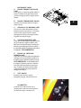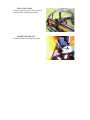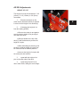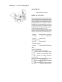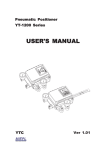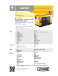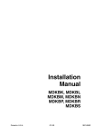
1
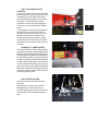
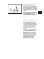
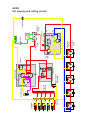
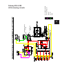
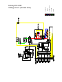
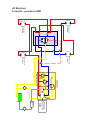
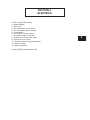
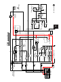
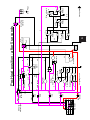
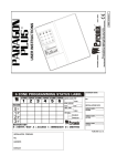
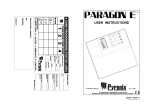
®
Service Course Manual
AR 250, Fairway 250 & 305
WARNING: If incorrectly used this machine can cause severe
injury. Those who use and maintain this machine should be
trained in its proper use, warned of its dangers and should
read the entire manual before attempting to set up, operate,
adjust or service the machine.
GB
INDEX
SPECIFICATIONS
1
CONTROLS
2
HYDRAULICS
3
ELECTRICS
4
NOTES
5
SECTION 1
SPECIFICATIONS
AR250 rider rotary
ENGINE SPECIFICATION
Type:
Power:
Firing order:
Maximum Speed:
Idle speed:
Oil sump capacity:
Oil type:
Fuel Capacity:
Fuel type:
Kubota V1505-BBS-EC-1, 4 cylinder (in line) vertical Diesel engine, 4
stroke, water cooled, 1498cc (91.44 cu.in) with 12V electric start.
28KW (38HP) @ 3000 ± 50 RPM (no load)
1, 3, 4, 2.
3000 ± 50 RPM (no load)
1500 +100 -0 RPM
6 Litres
SAE 10w-30
45.4 Litres
No. 2-D Diesel fuel (ASTM D975)
MACHINE SPECIFICATION
DIMENSIONS
Width of cut:
Overall length:
Overall width:
Transport width:
Overall height:
Overall weight:
2.5m
3.1m
2.6m
2.13m
1.4m
1270kg
CAPACITIES
Cooling system:
Hydraulic oil Tank:
Hydraulic oil Type:
4 Litres, 50/50 water antifreeze mix
37.8 Litres
SAE 10W-30.
WHEELS & TYRES
Front tyres:
Rear tyres:
Speeds (cutting fwd):
Speeds (cutting rev):
Speeds (Transport fwd):
Tyre pressure:
26.5 x 14.00 - 12 4 ply rating turf tread
20 x 10.00 - 8 4 ply rating turf tread
0 - 12 km/hr (0 - 7.5 mph)
0 - 6.4 km/hr (0 - 4 mph)
0 - 16 km/hr (0 - 8.5 mph)
1 kg/cm2 (14 psi) (all tyres)
CUTTING SPECIFICATIONS
Construction:
Cutter decks:
Cutting blades:
Height of cut:
Cutting performance:
Rear roller:
Page 2
Heavy duty welded pressed steel
Five 559mm (22”) rotary mulching decks supported by equal ratio lift
arms.
Patent pending twin blades. Lower blade 559mm (22”), upper blade
546mm (21.5”).
19mm to 133mm (3/4” to 5 1/4”)
Adjustable in 6mm (0.25”) increments, no tool required.
2.3ha/hr @ 12km/h (5.6 acres/hr @ 7.5 mph)
102mm (4”) diameter smooth roller.
1
HYDRAULIC DETAIL
TRANSMISSION
Pump:
Boost (Charge) Pump:
Front wheel motors:
Rear wheel motors:
Sauer Sundstrand MPV035D 35cc, 102 litres per minute @ 3000rpm.
Main relief valves 2500psi.
Part of main transmission pump, relief valve 200psi
Parker ME29 - ME29219AAAF 29.1 cu in/rev
Parker ME21 - ME210208AAJC 20.6 cu in/rev
CUTTING
Pump:
Relief Valve:
Motors:
STEERING AND LIFT
Pump:
Steering Valve:
Lift Valve:
Relief valve:
Casappa 50 litres per minute @ 3000rpm
3000psi located on deck control valve
Casappa PLM20 16L0-A307-L0 1.01 cu in/rev, spindle speed 3000rpm
blade tip speed 17000 ft/min approx.
Integral relief valve 1015psi each motor.
Casappa 19.15 litres per minute @ 3000rpm
Ross 5 port priority
Dukes/danfoss
Steering and lift relief valve test port located on the aluminium junction
block under the 4WD valve, 1200psi relief.
Fairway 250 & 305
1
ENGINE SPECIFICATION
Fairway 305
Type:
Power:
Firing order:
Maximum Speed:
Idle speed:
Oil sump capacity:
Oil type:
Fuel Capacity:
Fuel type:
Kubota V1505-BBS-EC-1, 4 cylinder (in line) vertical Diesel engine, 4
stroke, water cooled, 1498cc (91.44 cu.in) with 12V electric start.
28KW (38HP) @ 3000 ± 50 RPM (no load)
1, 3, 4, 2.
3000 ± 50 RPM (no load)
1500 +100 -0 RPM
6 Litres
SAE 10w-30
45.4 Litres
No. 2-D Diesel fuel (ASTM D975)
Fairway 250
Type:
Power:
Firing order:
Maximum Speed:
Idle speed:
Oil sump capacity:
Oil type:
Fuel Capacity:
Fuel type:
Kubota V1305-BBS-EC-1, 4 cylinder (in line) vertical Diesel engine, 4
stroke, water cooled, 1335cc (81.47 cu.in) with 12V electric start.
25KW (33HP) @ 3000 ± 50 RPM (no load)
1, 3, 4, 2.
3000 ± 50 RPM (no load)
1500 +100 -0 RPM
6 Litres
SAE 10w-30
45.4 Litres
No. 2-D Diesel fuel (ASTM D975)
MACHINE SPECIFICATION
DIMENSIONS
Width of cut:
Overall length:
Overall width:
Overall height:
Overall weight:
(Fairway 250)
2.94 (2.49)
2.88m (2.91)
2.52m (2.13)
1.6m (1.6)
1515Kg (1270)
CAPACITIES
Cooling system:
Hydraulic oil Tank:
Hydraulic oil Type:
5 Litres, 50/50 water antifreeze mix
37.8 Litres
SAE 10W-30.
WHEELS & TYRES
Front tyres:
Rear tyres:
Speeds (cutting fwd):
Speeds (cutting rev):
Speeds (Transport fwd):
Tyre pressure:
26.5 x 14.00 - 12 4 ply rating turf tread
20 x 10.00 - 8 4 ply rating turf tread
0 - 12 km/hr (0 - 7.5 mph)
0 - 6.4 km/hr (0 - 4 mph)
0 - 16 km/hr (0 - 8.5 mph)
1 kg/cm2 (14 psi) (all tyres)
SECTION 2
CONTROLS
STARTER KEY SWITCH
The starter key (A) should be turned
clockwise to the 'pre-heat' (No. 2) position
to heat the glowplugs when the green
warning lamp goes out, on warning lamp
disply module, turn the starter key
clockwise to the 'start' (No. 3) position to
start the engine. After starting, the key
should be released and allowed to return
automatically to the 'on' (No. 1) position for
normal running.
THROTTLE CONTROL LEVER
The lever (B) should be moved away from
the operator to increase the engine speed
STEERING WHEEL RAKE
ADJUSTMENT
The steering wheel is adjustable for rake.
The clamping release knob (A) is situated
on the side of the control console on the left
hand side. To adjust turn the clamping knob
anticlockwise to release and pivot the
steering wheel backwards and forwards to
obtain desired setting then lock in position
by turning clamping knob clockwise.
TRACTION FOOT PEDAL
To move the machine forward press the
front of the foot pedal (A). To reverse
depress the rear of the foot pedal. When
the pedal is released it will return to its
NEUTRAL LATCH (B)
Has two functions:
1.
The engine cannot be started
when the Neutral Latch is depressed.
2.
The FWD/REV pedal will not
work as described if the Neutral Latch is
2
SPEED LIMITER
The speed limiter (A) is operated by
pivoting the lever under the footpedal.
When positioned under the footpedal the
machine is limited to cutting speed, when
PARK BRAKES
Push the pedal forward (A) until it locks to
set parking brake. Release parking brake
by pushing the brake pedal at the same
HYDRAULIC LIFT LEVER
The cutting units can be raised and
lowered by control lever (A) situated on the
right hand side of the operators seat and
can be operated as follows:
To lift: Move the lever backwards and hold
in position until the units are at the
required height.
To lower: Move the lever forwards and hold
in this position, the units will lower to
ground level. The lever automatically
returns to a neutral position when
released.
NOTE: If any unit is raised out of work
then lowered into work again the blades
UNIT COUNTERBALANCE
CONTROL
Cutting unit ground pressure can be varied
within preset limits and is controlled by the
handwheel (A) on the right hand side of
the operator's seat located next to the lift/
lower lever. The handwheel is turned
clockwise to reduce the groundweight of
the cutting unit, improving slope climbing
ability.
The handwheel is turned anti clockwise to
increase the ground weight of the unit.
Increased down pressure will reduce the
likelyhood of cutting unit bounce when
cutting undulating ground. When cutting
level ground the normal setting is midway
way between the maximum and minimum
positions.
VARIABLE CYLINDER SPEED
The speed of rotation of the cutting cylinders
is adjustable by means of the handwheel (A)
situated on the left hand side of the operator.
Cylinder speed should be set to maximum in
normal cutting conditions. In very long growth
conditions, cylinder speed should be reduced
to obtain best finish,cylinder speed should
also be reduced when cutting very short, dry
grass to prevent excesive cylinder and bottom
blade wear. Rotate the hand wheel clockwise
to increase cylinder speed, anticlockwise to
decrease cylinder speed.
BACKLAPPING LEVER
Sets reel rotational direction with three
positions:
(a) forward for mowing, (b) reverse for
backlapping and (c) neutral. See the
separate cutting unit operator's manual for
an explanation of the backlapping procedure.
2
6.12 CUTTING UNIT SWITCHES
To commence cutting ensure speed
limiter is in mow position and the units
have been lowered. Push bottom of the
rocker switch (G) and depress foot switch
(A) Push top of rocker switch to stop
6.13 UNIT TRANSPORT STOP
Depressing the pedal (A) while lifting the
cutting units allows the cutting units to be
INSTRUMENT PANEL
A.
ENGINE PREHEAT INDICATOR
LAMP
Colour green, on when the ignition switch is
turned clockwise to the pre-heat position.
Once the lamp goes out the engine can be
started.
B.
ENGINE TEMPARATURE GUAGE
Indicates current temparature of engine,
whilst running.
C.
HYDRAULIC OIL WARNING LAMP
Colour red, on when the hydraulic oil temperature reaches a preset level. If the lamp
comes on bring the machine to a stop,
disengage the cutting units, apply the parking brake and stop the engine.
D.
CHARGING WARNING LAMP
Colour red, on when ignition is switched on and
will go out when the engine is started. If the
light comes on while the engine is running, the
fan belt may be slipping or broken or a fault in
the electrical system is indicated and should be
investigated. STOP IMMEDIATELY.
E.
ENGINE OIL PRESSURE
WARNING LAMP
Colour red, on when the ignition is switched on,
and will go out once the engine has started. If
the light comes on while the engine is running STOP IMMEDIATELY as this indicates that
the engine oil pressure is too low. Check the
level of oil in the sump and top up as necessary. Check the oil pressure sender switch.
Continued operation may cause extensive
damage to the engine.
F.
FUEL GUAGE
Located to the left of the engine
temparature guage. Monitors fuel level.
HOURMETER
Located on the lefthand side of the
steering tower, above the parking brake.
(A) Records engine running hours.
2
REEL STOP LEVER
Friction control that keeps cutting unit from
bouncing when operating over rough
BONNET RELEASE KEY
Release bonnet by inserting key (A) into
AR 250 Adjustments
HEIGHT OF CUT
The height of cut can be set between: 3/4"
(19mm) - 5 1/4" (133mm) in 1/4" (6mm)
Increments.
1.
Examine the decals on the
cutter deck to determine which pin position
is correct for the height of cut desired.(A)
2.
If changing the height of cut
from the existing position:
a.Remove the cotter pin and washer
securing the two height of cut pins (B) at
one side of the deck.
b.Grasp a handle on the top of the
deck (C) and simultaneously remove the
height of cut pins.
c.While still holding the handle, guide
the deck so that the height of cut pins can
be reinserted into the desired positions.
d.resecure the height of cut pins with
the cotter pins and washers.
3
repeat with the height of cut
pins on the other side of the deck.
4.
repeat steps 2 and 3 for all
other cutter decks, setting the same height
2
Fairway / T - Plex Cutting Unit
ADJUSTMENTS
Read Safety Instructions
HEIGHT OF CUT (FIG.2)
Fig.2
It is important to set the rear roll parallel to the
bottom blade (bedknife) in order to achieve the
minimum height of cut setting for the three
ranges of height, in the three sets of mounting
housing (D) bolt holes. Positions 'A','B' &'C'.
Setting the minimum height with the mounting
housings (D) in position 'A' will allow minimum
height and parallelism to be achieved in each
of the other two positions 'B' & 'C'.
Once the range has been chosen the actual
height of cut is set by adjusting the front roll
only by carriage screws (F) and locknuts (J).
Height of
cut range
minimum height maximum
of cut
height of cut
Holes 'A'
6.0mm(1/4in)
23.0mm(29/32in)
Holes 'B'
13.8mm(9/16in)
30.0mm(1 3/16in)
Holes 'C'
21.7mm(27/32in) 38.0mm(1
1/2in)
TO SET REAR ROLL
with a new bottom blade (bedknife)
1.
Set the height of cut setting bar (G)as
follows:
a.
Screw X to 6mm(1/4in) under
the head.
b.
Screw Y to 5.2mm (7/32in) to
screw thread
tip.
Note: The difference between screw X and
screw Y is
0.8mm (1/32in).
2.
Set roll carriage mounting housing(D)
bolts into
holes 'A'.
3.
Place the setting bar (G)as shown at
one end of
the bottom blade with the
CUTTING CYLINDER TO BOTTOM
BLADE ADJUSTMENT (FIG.3)
To check that the cutting cylinder is set to
the bottom blade correctly, hold a piece of
thin paper between the edge of the blade
and the spiral cutters and turn the cylinder
manually.
Fig.3
The paper should be cut cleanly along the
total length of the bottom blade, if not,
some adjustment may be necessary, BUT
DO NOT OVERTIGHTEN. Alternatively if
the cylinder is worn it may require back
lapping before adjusting.
To adjust:
1. To adjust the cylinder to the bottom
blade lift and turn alternately left and right
hand handwheels (A Fig.3). (clockwise to
put on cut anticlockwise to take off cut)
and release, keep turning the handwheel
until it locates in the serrated locking ring.
The adjuster is of the notched type and
each notch is moving the cylinder in
increments of approximately 0.04mm
(0.0015in).
THIS IS A SELF LOCKING MECHANISM
THERE BEING NO NECESSITY TO
UNLOCK OR LOCK THE MECHANISM.
IMPORTANT: IN ROUGH GROUND
CONDITIONS IT MAY BE NECESSARY
TO LOCK THE NUTS SECURING THE
BEARING HOUSINGS TO THE SIDE
FRAME WHERE THEY RUN IN
ADJUSTING SLOTS TO RETAIN
CYLINDER TO BOTTOM BLADE
2
SECTION 3
HYDRAULICS
AR 250
1 - Lift and Cutting Circuit
Fairway 250 & 305
1 - Lift and Steer Circuit
2 - Cutting Circuit
3 - Backlapping Circuit
All Machines
1 - Transmission Circuit
3
4
Return
Manifold
Lift/lower
rams
1
Pressure
Manifold
Steering ram
5
Weight transfer
valve 350psi
Lift Valve
Steering valve
2
RV
C
T
RV 1
3000 psi
1200 psi
3
P
G
Cutter deck
motors
Relief valve
1015psi
C
G
Steering & Lift
Pump
RV 2
300 psi
CV
M2
M1
Cutter Deck
Valve
SV
Oil Cooler
Cutter Deck
Pump
Inlet
Manifold
Filter
Tank
AR250
Lift, steering and cutting circuits
.052
.052
.089
RV
1200
psi
SV
RV
PC
Cutting Pump
30 Lpm
Steering & Lift Pump
17.11Lpm
FAIRWAY 250 & 305 STEERING & LIFT CIRCUIT
DRAIN
SUCTION
CHARGE
STEERING PRESSURE
W/T VARIABLE PRESSURE
Fairway 250 & 305
Lift & steering circuits
3
.052
.052
.089
RV
960
psi
3
2
RV
5
SV
1
PC
4
DRAIN
SUCTION
VARIABLE FLOW
RETURN
PRESSURE
Fairway 250 & 305
Cutting circuit - (forward drive)
.052
.052
.089
RV
960
psi
3
2
RV
5
SV
1
PC
4
Cutting Pump
30 Lpm
Steering & Lift Pump
17.11Lpm
DRAIN
SUCTION
VARIABLE FLOW
RETURN
PRESSURE
Fairway 250 & 305
Cutting circuit - (backlapping)
3
Engine
Kubota
V1505-BBS-EC-1
Rpm min = 1500
max = 3000
Inlet
manifold
Charge Relief
Valve 200psi
R
F
M35 Sundstrand pump
Left rear
wheel motor
Left front
wheel motor
F
H
G
E
I
Right rear
wheel motor
D
C
B
A
Right front
wheel motor
All Machines
Forwards - permanent 4WD
SECTION 4
ELECTRICS
AR 250 - Electical Schematics
1 - Master Diagram
2 - Hot Circuit
3 - Pre heat position 1st 5 seconds
4 - Pre Heat position after 5 seconds
5 - Crank position
6 - Run position - driving machine
7 - Press mow switch - cut position
8 - Drop decks - activate cutter switch
9 - Lift lower lever to neutral
10 - Press foot switch to engage deck drive
11 - Machine cutting
12 - Raise cutter decks
Fairway 305 (EC) electrical schematic
4
G/W
O/BL
40A Circuit
breaker
Fuse 3
10A
O/BR
Fuse 2
10A
Fuse 4
20A
Fuse 1
30A
R/W
Glow plug
timer relay
R/W
30 AC 19 50
Key Switch
Off
Preheat
Crank
Run
Glow plug
indicator light
O
O
PK
To lighting circuit
O/B
Eng Oil Temp
P
B/W
Y/B
B
Sender
Sender
86
87
B
Relay 2
Start
85
30
87a
Starter Motor
G/Y
Alternator
B
DB
B
BR
LB
R
R
Battery
Hold
Electric Circuit
BL/Y
Temp Gauge
Eng Oil pressure
Fuel
Gauge
O
O
Battery
warning light
Hourmeter
4WD switch
R/W
Mow
switch
BL/W
Fuse 5
5A
W/BL
Neutral switch
Seat switch
O
Seat switch delay
B
G
Pull
86
G
B
G
87
87a
Relay 4
85
30
O
G
W/B
Foot switch
NB
Lower switch
Y
Raise switch
GR
R
ETR
Solenoid
87
87a
85
B
30
B
W/B
B
85
W/B
30
Relay 3
86
B
87
87a
W/R
W/R
O
Glow Plugs
Mow solenoid
W/B
Relay 1
86
W/B
NB
Glow Plug
Contactor
G/W
O/BL
40A Circuit
breaker
Fuse 3
10A
O/BR
Fuse 2
10A
Fuse 4
20A
Fuse 1
30A
R/W
Glow plug
timer relay
R/W
30 AC 19 50
Key Switch
Off
Preheat
Crank
Run
Glow plug
indicator light
O
O
PK
To lighting circuit
O/B
Eng Oil Temp
P
B/W
Y/B
B
Sender
Sender
86
87
87a
B
Starter Motor
G/Y
Alternator
B
DB
B
BR
LB
R
R
Battery
Hold
Off position
Relay 2
Start
85
30
BL/Y
Temp Gauge
Eng Oil pressure
Fuel
Gauge
O
O
Battery
warning light
Hourmeter
4WD switch
R/W
Mow
switch
BL/W
Fuse 5
5A
W/BL
Neutral switch
Seat switch
O
Seat switch delay
B
G
Pull
86
G
B
G
87
87a
Relay 4
85
30
O
G
W/B
Foot switch
NB
Lower switch
Y
Raise switch
GR
R
ETR
Solenoid
4
87
87a
85
B
30
B
85
W/B
30
Relay 3
86
B
87
87a
W/R
Pre heat position
W/B
B
W/R
O
Glow Plugs
Mow solenoid
W/B
Relay 1
86
W/B
NB
Glow Plug
Contactor
G/W
O/BL
40A Circuit
breaker
Fuse 3
10A
O/BR
Fuse 2
10A
Fuse 4
20A
Fuse 1
30A
R/W
Glow plug
timer relay
R/W
30 AC 19 50
Key Switch
Off
Preheat
Crank
Run
Glow plug
indicator light
O
O
PK
To lighting circuit
O/B
Eng Oil Temp
P
B/W
Y/B
B
Sender
Sender
86
87
87a
B
Relay 2
Start
85
30
BL/Y
Temp Gauge
Eng Oil pressure
Fuel
Gauge
O
O
Battery
warning light
Hourmeter
4WD switch
R/W
Mow
switch
BL/W
Fuse 5
5A
W/BL
Neutral switch
Seat switch
O
Seat switch delay
B
G
Starter Motor
G/Y
Alternator
B
DB
B
BR
LB
R
R
Battery
Hold
Pull
86
G
B
G
87
87a
Relay 4
85
30
O
G
W/B
Foot switch
NB
Lower switch
Y
Raise switch
GR
R
ETR
Solenoid
Pre-Heat position - 1st 5 seconds
87
87a
85
B
30
B
85
W/B
30
Relay 3
86
B
87
87a
W/R
After 5 seconds
W/B
B
W/R
O
Glow Plugs
Mow solenoid
W/B
Relay 1
86
W/B
NB
Glow Plug
Contactor
G/W
O/BL
40A Circuit
breaker
Fuse 3
10A
O/BR
Fuse 2
10A
Fuse 4
20A
Fuse 1
30A
R/W
Glow plug
timer relay
R/W
30 AC 19 50
Key Switch
Off
Preheat
Crank
Run
Glow plug
indicator light
O
O
PK
To lighting circuit
O/B
Eng Oil Temp
P
B/W
Y/B
B
Sender
Sender
86
87
87a
B
Relay 2
Start
85
30
BL/Y
Temp Gauge
Eng Oil pressure
Fuel
Gauge
O
O
Battery
warning light
Hourmeter
4WD switch
R/W
Mow
switch
BL/W
Fuse 5
5A
W/BL
Neutral switch
Seat switch
O
Seat switch delay
B
G
Starter Motor
G/Y
Alternator
B
DB
B
BR
LB
R
R
Battery
Hold
Pull
86
G
B
G
87
87a
Relay 4
85
30
O
G
W/B
Foot switch
NB
Lower switch
Y
Raise switch
GR
R
ETR
Solenoid
87
87a
85
B
30
B
85
W/B
30
Relay 3
86
B
87
87a
W/R
Crank position
W/B
B
W/R
O
Glow Plugs
Mow solenoid
W/B
Relay 1
86
W/B
NB
Glow Plug
Contactor
Pre-Heat position - after 5 seconds
4
G/W
O/BL
40A Circuit
breaker
Fuse 3
10A
O/BR
Fuse 2
10A
Fuse 4
20A
Fuse 1
30A
R/W
Glow plug
timer relay
R/W
30 AC 19 50
Key Switch
Off
Preheat
Crank
Run
Glow plug
indicator light
O
O
PK
To lighting circuit
O/B
Eng Oil Temp
P
B/W
Y/B
B
Sender
Sender
86
B
Relay 2
Start
85
87
87a
Starter Motor
G/Y
Alternator
B
DB
B
BR
LB
R
R
Battery
Hold
Crank position
30
BL/Y
Temp Gauge
Eng Oil pressure
Fuel
Gauge
O
O
Battery
warning light
Hourmeter
4WD switch
R/W
Mow
switch
BL/W
Fuse 5
5A
W/BL
Neutral switch
Seat switch
O
Seat switch delay
B
G
Pull
86
G
B
G
87
87a
Relay 4
85
30
O
G
W/B
Foot switch
NB
Lower switch
Y
Raise switch
GR
R
ETR
Solenoid
87
87a
85
B
30
B
85
W/B
30
Relay 3
86
B
87
87a
W/R
Run position
W/B
B
W/R
O
Glow Plugs
Mow solenoid
W/B
Relay 1
86
W/B
NB
Glow Plug
Contactor
G/W
O/BL
40A Circuit
breaker
Fuse 3
10A
O/BR
Fuse 2
10A
Fuse 4
20A
Fuse 1
30A
R/W
Glow plug
timer relay
R/W
30 AC 19 50
Key Switch
Off
Preheat
Crank
Run
Glow plug
indicator light
O
O
PK
To lighting circuit
O/B
Eng Oil Temp
P
B/W
Y/B
B
Sender
Sender
86
87
87a
B
Relay 2
Start
85
30
BL/Y
Temp Gauge
Eng Oil pressure
Fuel
Gauge
O
O
Battery
warning light
Hourmeter
4WD switch
R/W
Mow
switch
BL/W
Fuse 5
5A
W/BL
Neutral switch
Seat switch
O
Seat switch delay
B
G
Starter Motor
G/Y
Alternator
B
DB
B
BR
LB
R
R
Battery
Hold
Pull
86
G
B
G
87
87a
Relay 4
85
30
O
G
W/B
Foot switch
NB
Lower switch
Y
Raise switch
GR
R
ETR
Solenoid
Run position - Driving machine
4
87
87a
85
B
30
B
85
W/B
30
Relay 3
86
B
87
87a
W/R
Press mow switch
W/B
B
W/R
O
Glow Plugs
Mow solenoid
W/B
Relay 1
86
W/B
NB
Glow Plug
Contactor
G/W
O/BL
40A Circuit
breaker
Fuse 3
10A
O/BR
Fuse 2
10A
Fuse 4
20A
Fuse 1
30A
R/W
Glow plug
timer relay
R/W
30 AC 19 50
Key Switch
Off
Preheat
Crank
Run
Glow plug
indicator light
O
O
PK
To lighting circuit
O/B
Eng Oil Temp
P
B/W
Y/B
B
Sender
Sender
86
87
87a
B
Relay 2
Start
85
30
BL/Y
Temp Gauge
Eng Oil pressure
Fuel
Gauge
O
O
Battery
warning light
Hourmeter
4WD switch
R/W
Mow
switch
BL/W
Fuse 5
5A
W/BL
Neutral switch
Seat switch
O
Seat switch delay
B
G
Starter Motor
G/Y
Alternator
B
DB
B
BR
LB
R
R
Battery
Hold
Pull
86
G
B
G
87
87a
Relay 4
85
30
O
G
W/B
Foot switch
NB
Lower switch
Y
Raise switch
GR
R
ETR
Solenoid
Press mow switch - cut position
87
87a
85
B
30
B
85
W/B
30
Relay 3
86
B
87
87a
W/R
Drop cutter decks
W/B
B
W/R
O
Glow Plugs
Mow solenoid
W/B
Relay 1
86
W/B
NB
Glow Plug
Contactor
G/W
O/BL
40A Circuit
breaker
Fuse 3
10A
O/BR
Fuse 2
10A
Fuse 4
20A
Fuse 1
30A
R/W
Glow plug
timer relay
R/W
30 AC 19 50
Key Switch
Off
Preheat
Crank
Run
Glow plug
indicator light
O
O
PK
To lighting circuit
O/B
Eng Oil Temp
P
B/W
Y/B
B
Sender
Sender
86
87
87a
B
Relay 2
Start
85
30
BL/Y
Temp Gauge
Eng Oil pressure
Fuel
Gauge
O
O
Battery
warning light
Hourmeter
4WD switch
R/W
Mow
switch
BL/W
Fuse 5
5A
W/BL
Neutral switch
Seat switch
O
Seat switch delay
B
G
Starter Motor
G/Y
Alternator
B
DB
B
BR
LB
R
R
Battery
Hold
Pull
86
G
B
G
87
87a
Relay 4
85
30
O
G
W/B
Foot switch
NB
Lower switch
Y
Raise switch
GR
R
ETR
Solenoid
87
87a
85
B
30
B
85
W/B
30
Relay 3
86
B
87
87a
W/R
Release lower lever
W/B
B
W/R
O
Glow Plugs
Mow solenoid
W/B
Relay 1
86
W/B
NB
Glow Plug
Contactor
Drop cutter decks - actuates lower switch
4
G/W
O/BL
40A Circuit
breaker
Fuse 3
10A
O/BR
Fuse 2
10A
Fuse 4
20A
Fuse 1
30A
R/W
Glow plug
timer relay
R/W
30 AC 19 50
Key Switch
Off
Preheat
Crank
Run
Glow plug
indicator light
O
O
PK
To lighting circuit
O/B
Eng Oil Temp
P
B/W
Y/B
B
Sender
Sender
86
87
87a
B
Relay 2
Start
85
30
BL/Y
Temp Gauge
Eng Oil pressure
Fuel
Gauge
O
O
Battery
warning light
Hourmeter
4WD switch
R/W
Mow
switch
BL/W
Fuse 5
5A
W/BL
Neutral switch
Seat switch
O
Seat switch delay
B
G
Starter Motor
G/Y
Alternator
B
DB
B
BR
LB
R
R
Battery
Hold
Pull
86
G
B
G
87
87a
Relay 4
85
30
O
G
W/B
Foot switch
NB
Lower switch
Y
Raise switch
GR
R
ETR
Solenoid
Lift/lower lever to neutral
87
87a
85
B
30
B
85
W/B
30
Relay 3
86
B
87
87a
W/R
Press foot switch
W/B
B
W/R
O
Glow Plugs
Mow solenoid
W/B
Relay 1
86
W/B
NB
Glow Plug
Contactor
G/W
O/BL
40A Circuit
breaker
Fuse 3
10A
O/BR
Fuse 2
10A
Fuse 4
20A
Fuse 1
30A
R/W
Glow plug
timer relay
R/W
30 AC 19 50
Key Switch
Off
Preheat
Crank
Run
Glow plug
indicator light
O
O
PK
To lighting circuit
O/B
Eng Oil Temp
P
B/W
Y/B
B
Sender
Sender
86
87
87a
B
Relay 2
Start
85
30
BL/Y
Temp Gauge
Eng Oil pressure
Fuel
Gauge
O
O
Battery
warning light
Hourmeter
4WD switch
R/W
Mow
switch
BL/W
Fuse 5
5A
W/BL
Neutral switch
Seat switch
O
Seat switch delay
B
G
Starter Motor
G/Y
Alternator
B
DB
B
BR
LB
R
R
Battery
Hold
Pull
86
G
B
G
87
87a
Relay 4
85
30
O
G
W/B
Foot switch
NB
Lower switch
Y
Raise switch
GR
R
ETR
Solenoid
87
87a
85
B
30
B
85
W/B
30
Relay 3
86
B
87
87a
W/R
Release foot switch
W/B
B
W/R
O
Glow Plugs
Mow solenoid
W/B
Relay 1
86
W/B
NB
Glow Plug
Contactor
Press footswitch to engage deck drive
4
G/W
O/BL
40A Circuit
breaker
Fuse 3
10A
O/BR
Fuse 2
10A
Fuse 4
20A
Fuse 1
30A
R/W
Glow plug
timer relay
R/W
30 AC 19 50
Key Switch
Off
Preheat
Crank
Run
Glow plug
indicator light
O
O
PK
To lighting circuit
O/B
Eng Oil Temp
P
B/W
Y/B
B
Sender
Sender
86
87
87a
B
Relay 2
Start
85
30
BL/Y
Temp Gauge
Eng Oil pressure
Fuel
Gauge
O
O
Battery
warning light
Hourmeter
4WD switch
R/W
Mow
switch
BL/W
Fuse 5
5A
W/BL
Neutral switch
Seat switch
O
Starter Motor
G/Y
Alternator
B
DB
B
BR
LB
R
R
Battery
Hold
Pull
86
G
B
G
87
87a
Relay 4
85
30
O
G
W/B
Foot switch
NB
Lower switch
Y
Raise switch
GR
R
ETR
Solenoid
Circuit shown cutting
Seat switch delay
B
G
87
87a
85
B
30
B
85
W/B
30
Relay 3
86
B
87
87a
W/R
Raise cutter decks
W/B
B
W/R
O
Glow Plugs
Mow solenoid
W/B
Relay 1
86
W/B
NB
Glow Plug
Contactor
G/W
O/BL
40A Circuit
breaker
Fuse 3
10A
O/BR
Fuse 2
10A
Fuse 4
20A
Fuse 1
30A
R/W
Glow plug
timer relay
R/W
30 AC 19 50
Key Switch
Off
Preheat
Crank
Run
Glow plug
indicator light
O
O
PK
To lighting circuit
O/B
Eng Oil Temp
P
B/W
Y/B
B
Sender
Sender
86
87
87a
B
Relay 2
Start
85
30
BL/Y
Temp Gauge
Eng Oil pressure
Fuel
Gauge
O
O
Battery
warning light
Hourmeter
4WD switch
R/W
Mow
switch
BL/W
Fuse 5
5A
W/BL
Neutral switch
Seat switch
O
Starter Motor
G/Y
Alternator
B
DB
B
BR
LB
R
R
Battery
Hold
Pull
86
G
B
G
87
87a
Relay 4
85
30
O
G
W/B
Foot switch
NB
Lower switch
Y
Raise switch
GR
R
ETR
Solenoid
Raise cutter decks
Seat switch delay
B
G
4
87
87a
85
B
30
B
85
W/B
30
Relay 3
86
B
87
87a
W/R
Raise cutter decks
W/B
B
W/R
O
Glow Plugs
Mow solenoid
W/B
Relay 1
86
W/B
NB
Glow Plug
Contactor
Fairway 305 (EC) Electric Circuits
12v Pos
Acc Circuit
Preheat Circuit
Crank Circuit
Cutting Circuit
Earth
Switched Negative
NOTE
Wires only join at T junctions
& not at crossovers
KEY
SECTION 5
NOTES
5
NOTES
NOTES
5
NOTES
NOTES
5
NOTES
NOTES
5
NOTES
NOTES
5
NOTES
®
GB
World Class Quality, Performance and Support
Equipment from Ransomes Jacobsen Limited is built to
exacting standards ensured by ISO 9001 registration at
all our manufacturing locations. A worldwide dealer
network and factory-trained technicians backed by
Ransomes Jacobsen Parts Xpress provide reliable,
high-quality product support.
BOB-CAT BUNTON CUSHMAN JACOBSEN RANSOMES RYAN
Ransomes Jacobsen Limited
Central Avenue, Ransomes Europark, Ipswich, England, IP3 9QG
English Company Registration No. 1070731
www.textronsolutions.com