1
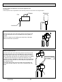
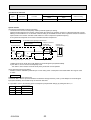
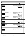
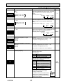
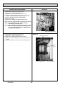
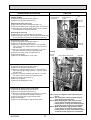
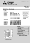
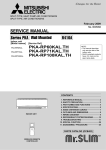
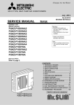
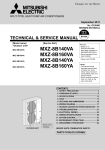
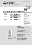
Check method of DC fan motor (fan motor/outdoor controller circuit board)
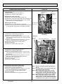
Notes
· High voltage is applied to the connecter (CNF1, 2) for the fan motor. Pay attention to the service.
· Do not pull out the connector (CNF1, 2) for the motor with the power supply on.
(It causes trouble of the outdoor controller circuit board and fan motor.)
Self check
Symptom : The outdoor fan cannot turn around.
Fuse check
Check the fuse (F5) on outdoor
controller board.
Replace outdoor controller board (C.B)
and fan motor (MF1, 2).
Yes
Did the fuse blow?
No
Wiring contact check
Contact of fan motor connector (CNF1, 2)
Recover wiring.
Yes
Is there contact failure?
No
Power supply check (Remove the connector (CNF1, 2))
Measure the voltage in the outdoor controller circuit board.
TEST POINT : VDC (between 1 (+) and 4 (-) of the fan connector): VDC DC250~330V
TEST POINT : VCC (between 5 (+) and 4 (-) of the fan connector): VCC DC15V
Is the voltage normal?
Replace the fan motor.
Yes
Yes
No
OK
Check the operation of fan.
Replace outdoor
controller board.
END
NG
Replace outdoor controller board.
OK
Check the operation.
END
NG
Replace the fan motor.
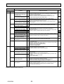
10-6. HOW TO CHECK THE COMPONENTS
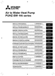
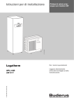
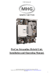
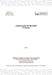
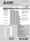
<HIGH PRESSURE SENSOR>
Vout (V)
MULTI
CONTROLLER BOARD
4.5
WHT
SENSOR
2.5
Vout BLU
2
BLK
1
63HS
0.5
2.5
OCH533A
5V DC
3
5
-
: 5V (DC)
-
: Output Vout (DC)
PRESSURE
(MPa)
41
MICRO
PROCESSOR
GND
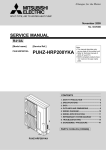
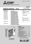
<Thermistor feature chart>
50
Low temperature thermistors
• Thermistor <Liquid> (TH3)
• Thermistor <2-phase pipe> (TH6)
• Thermistor <Ambient> (TH7)
Resistance (k)
40
Thermistor R0 = 15k' ± 3%
B constant = 3480 ± 2%
Rt =15exp{3480(
0:
10:
20:
25:
15k'
9.6k'
6.3k'
5.2k'
1
1
)}
–
273+t 273
30:
4.3k'
40:
3.0k'
30
20
10
0
-20 -10 0 10 20 30 40 50
Temperature ()
200
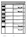
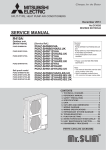
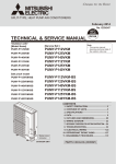
Medium temperature thermistor
• Thermistor <Heatsink> (TH8)
Thermistor R50 = 17k' ± 2%
B constant = 4150 ± 3%
Resistance (k)
150
1
1
Rt =17exp{4150( 273+t – 323)}
0:
25:
50:
70:
90:
180k'
50k'
17k'
8k'
4k'
100
50
0
25
50
75
100
Temperature ()
125
500
High temperature thermistor
• Thermistor <Discharge> (TH4)
• Thermistor <Comp. surface> (TH34)
400
Resistance (k)
Thermistor R120 = 7.465k' ± 2%
B constant = 4057 ± 2%
1
1
Rt =7.465exp{4057( 273+t – 393)}
20: 250k'
30: 160k'
40: 104k'
50: 70k'
60: 48k'
70:
34k'
80:
24k'
90: 17.5k'
100: 13.0k'
110: 9.8k'
300
200
100
0
OCH533A
42
25
50
75
Temperature ()
100
120
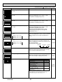
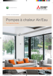
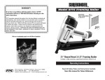
Linear expansion valve
(1) Operation summary of the linear expansion valve
• Linear expansion valve opens/closes through stepping motor after receiving the pulse signal from the outdoor controller board.
• Valve position can be changed in proportion to the number of pulse signal.
<Connection between the outdoor controller board and the linear expansion valve>
Outdoor controller board
DC12V
Gray
LEV
1
Drive circuit
3
M
2
1
5
4
:4
:4
3
:3
:2
Yellow 4
:2
:1
Black
5
:1
:3
6
Orange 2
Red
Connector LEV-A
LEV-B
<Output pulse signal and the valve operation>
Output
(Phase)
Output
1
2
3
5
4
6
7
8
:1
ON ON OFF OFF OFF OFF OFF ON
:2
OFF ON
:3
OFF OFF OFF ON ON ON OFF OFF
:4
OFF OFF OFF OFF OFF ON ON ON
ON ON OFF OFF OFF OFF
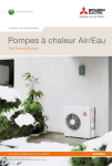
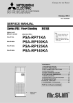
(2) Linear expansion valve operation
Valve position (capacity)
Opening a valve : 8 7 6 5 4 3 2 1 8
Closing a valve : 1 2 3 4 5 6 7 8 1
The output pulse shifts in above order.
· When linear expansion valve operation stops, all output phase
become OFF.
· When the switch is turned on, 700 pulse closing valve signal will
be sent till it goes to A point in order to define the valve position.
(The pulse signal is being sent for about 20 seconds.)
When the valve moves smoothly, there is no sound or vibration
occurring from the linear expansion valve : however, when the
pulse number moves from B to A or when the valve is locked,
more sound can be heard.
No sound is heard when the pulse number moves from B to A in
case coil is burnt out or motor is locked by open-phase.
Close
Open
· Sound can be detected by placing the ear against the screw driver handle while putting the screw driver to the linear expansion
valve.
500 pulse
Opening a valve
all the way
Pulse number
Extra tightning (about 32 pulse)
OCH533A
43
(3) How to attach and detach the coil of linear expansion valve
<Composition>
Linear expansion valve is separable into the main body and the coil as shown in the diagram below.
Stopper
Main body
Coil
Lead wire
<How to detach the coil>
Hold the lower part of the main body (shown as A) firmly so that
the main body does not move and detach the coil by pulling it
upward.
Be sure to detach the coil holding main body firmly. Otherwise
pipes can bend due to pressure.
A
<How to attach the coil>
Hold the lower part of the main body (shown as A) firmly so that
the main body does not move and attach the coil by inserting it
downward into the main body. Then securely attach the coil stopper to main body. (At this time, be careful that stress is not added
to lead wire and main body is not wound by lead wire.) If the
stopper is not firmly attached to main body, coil may be detached
from the main body and that can cause defective operation of linear expansion valve.
To prevent piping stress, be sure to attach the coil holding the
main body of linear expansion valve firmly. Otherwise pipe may
break.
Be sure to attach
the stopper.
A
OCH533A
44
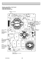
<CAUTION> TEST POINT1 is high voltage.
CNDC
DC280V-380V Connect
from outdoor power circuit
board for VHA, connect
from noise filter board for
YHA(CNDC)
}
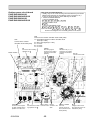
10-7. TEST POINT DIAGRAM
Outdoor controller circuit board
PUHZ-SW75VHA(-BS).UK
PUHZ-SW100VHA(-BS).UK
PUHZ-SW100YHA(-BS).UK
VCC (TEST POINT 2)
PUHZ-SW120VHA(-BS).UK
(voltage between pins of
PUHZ-SW120YHA(-BS).UK
C6B): DC 15V
+
–
VDC (TEST POINT 1)
(voltage between pins of C5E)
: DC250V-380V
VSP (TEST POINT 3)
CNS
(voltage between pins of
C5A, C5B): DC 0V (when
stopped), DC 1– 6.5V
(when operated)
(Indoor/outdoor unit
connecting wire)
VFG (TEST POINT 4)
(voltage between right
pins of PC5C and PC5D,
pin 3 and pin 4)
63H
High pressure
switch
CNAC
TH6
2 to 4: Power supply
for outdoor controller
circuit board (230V AC)
1 to 3: Power supply
for indoor and outdoor
unit connection wire
(230V AC)
Thermistor
<2-phase pipe>
TH7
Thermistor<Ambient>
TH3
Thermistor
<Outdoor pipe>
CN2
TH4
Connect to the outdoor
power circuit board (CN2)
1-5: Power circuit board
Transmitting signal to
the controller circuit board
(0-5V DC)
2-5: Zero cross signal
(0-5V DC)
3-4: Not used ...
(SW75V,100/120Y)
18V DC...(SW100/120V)
6-5: 16V DC
7-5: 16V DC
Thermistor <Discharge>
63HS
High pressure sensor
TH34
Thermistor
<Comp. surface>
LEV-A,-B
Linear expansion valve
[5: – 1,2,6,7: + ]
21S4
63L
Four-way valve
Low pressure switch
(SW100/120)
CN4
SW4
Transmission to outdoor power circuit
board (CN4)
Test operation
SW5
Function switch,
Model select
SW6
Model select
SW1
Forced defrost, detect
history record reset,
refrigerant address
SW9
CN52C
(Connect to the outdoor noise
filter circuit board (SW75V)/
the outdoor power circuit
board (SW100/120V))
Only for SW·VHA
OCH533A
Function switch
CN51
External signal output
• Compressor operating signal
• Abnormal signal
45
CNDM
SWP
Pump down
1 to 2: Input of low-level sound priority mode
1 to 3: Input of external contact point
SW7
Demand control setting
Outdoor noise filter circuit board
PUHZ-SW75VHA.UK
PUHZ-SW75VHA-BS.UK
EI, E2
Connect to the earth
LI, NI
Voltage of 230V
AC is input.
(Connect to the
terminal block
(TB1))
E3
Connect to
the earth
CNAC1, CNAC2
230V AC
(Connect to the
outdoor controller
circuit board
(CNAC))
CN5
Primary current
(Connect to the
outdoor power
circuit board
(CN5))
CN52C
52C relay signal
(Connect to the
outdoor controller
circuit board
(CN52C))
LO, NO
Voltage of 230V AC is output.
(Connect ACL)
OCH533A
46
Outdoor noise filter circuit board
PUHZ-SW100YHA.UK
PUHZ-SW100YHA-BS.UK
PUHZ-SW120YHA.UK
PUHZ-SW120YHA-BS.UK
LI1, LI2, LI3, NI
POWER SUPPLY
LI1-LI2/LI-LI3/LI3-LI1 : AC400V input
LI1-NI/LI2-NI/LI3-NI : AC230V input
(Connect to the terminal block (TB1))
GD1
Connect to the earth
GD3
Connect to the earth
CNAC2
AC230V
(Connect to the
outdoor controller
circuit board (CNAC))
CNDC
(Connect to the
outdoor controller
circuit board
(CNDC))
CNCT
Primary current
(Connect to the outdoor power circuit
board (CN5))
CNL
Connect to the ACL4
OCH533A
NO
Connect to the
outdoor converter
circuit board(N-IN)
LO1, LO2, LO3
POWER SUPPLY
LO1-LO2/LO2-LO3/LO3-LO1 : AC400V OUTPUT
(Connect to the outdoor converter circuit board and ACL(L1-IN, ACL2, ACL3))
47
Outdoor power circuit board
PUHZ-SW75VHA.UK
PUHZ-SW75VHA-BS.UK
Brief Check of DIP-IPM and DIP-PFC
* Usually, they are in a state of being short-circuited if they are broken.
Measure the resistance in the following points (connectors, etc.).
If they are short-circuited, it means that they are broken.
1. Check of DIP-IPM
P2 - U , P2 - V , P2 - W , N2 - U , N2 - V , N2 - W
2. Check of DIP-PFC
P1 - L , P1 - N , L - N1 , N - N1
Note:The marks L , N , N1 , N2 , P1 , P2 , U , V and W shown
in the diagram are not actually printed on the board.
R, S
Connect to the ACL
230V AC
U, V, W
Connect to the compressor (MC)
Voltage among phases: 5V to 180V AC
DIP-PFC
P1
LD1-LD2
280-380V DC
Connect to
the outdoor
controller
circuit board
(CNDC)
N
N2
L
W
N1
V
N1
U
LD9
Connect to
the earth
P2
DIP-IPM
CN2
Connect to the outdoor controller circuit board (CN2)
1-5:Outdoor power circuit board Transmitting signal
to the outdoor controller circuit board (0-5V DC)
2-5: Zero cross signal (0-5V DC)
3-4: Not used
1, 2, 6, 7 : +
6-5: 16V DC
5:–
7-5: 16V DC
[
OCH533A
]
CN3
Thermistor
<Heatsink>
(TH8)
48
CN4
Connect from the
outdoor controller
circuit board
(CN4)
CN5
Primary current detection
(Connect to the outdoor
noise filter circuit board
(CN5))
Outdoor power circuit board
PUHZ-SW100VHA.UK
PUHZ-SW100VHA-BS.UK
PUHZ-SW120VHA.UK
PUHZ-SW120VHA-BS.UK
Brief Check of POWER MODULE
* Usually, they are in a state of being short-circuited if they are broken.
Measure the resistance in the following points (connectors, etc.).
If they are short-circuited, it means that they are broken.
1. Check of POWER MODULE
1 Check of DIODE circuit
R - L1 , S - L1 , R - N1 , S - N1
2 Check of IGBT circuit
L2 - N1
3 Check of INVERTER circuit
P - U , P - V , P - W , N1 - U , N1 - V , N1 - W
Note: The marks R , S , L1 , L2 , P , N1 , U , V and W
shown in the diagram are not actually printed on the board.
CN2
Connect to the outdoor controller circuit board (CN2)
1-5: Transmitting signal to outdoor controller circuit
board (0-5 V DC)
2-5: Zero cross signal (0-5 V DC)
3-4: 18 V DC
6-5: 16 V DC
7-5: 16 V DC
CN52C
CNDC
CN4
Connect to the outdoor
controller circuit board (CN4)
N2
Power module
Connect to the smoothing
capacitor CB -
52C driving signal
Connect to the outdoor
controller circuit board
(CN52C)
S
W
V
U
L2
P
N1
R
L1
U/V/W
P2
Connect to the compressor (MC) Voltage among
phases: 10 V-180 V AC
Connect to the smooth- Connect to DCL Connect to the
ing capacitor CB +
earth
OCH533A
280-380 V DC (1+, 3-)
Connect to the outdoor
controller circuit board
E2, E3
(CNDC)
Connect to the earth
DCL1, DCL2
49
EI, E4
CNAC1, CNAC2
NI, LI
230 V AC
Connect to the outdoor controller circuit
board (CNAC)
Voltage of 230 V AC is
input (Connect to the terminal block (TB1))
Outdoor power circuit board
PUHZ-SW100YHA.UK
PUHZ-SW100YHA-BS.UK
PUHZ-SW120YHA.UK
PUHZ-SW120YHA-BS.UK
Brief Check of POWER MODULE
* Usually, they are in a state of being short-circuited if they are broken.
Measure the resistance in the following points (connectors, etc.).
If they are short-circuited, it means that they are broken.
1. Check of DIODE MODULE
L1 - P1 , L2 - P1 , L3 - P1 , L1 - N1 , L2 - N1 , L3 - N1
2. Check of DIP-IPM
P2 - U , P2 - V , P2 - W , N2 - U , N2 - V , N2 - W
Note: The marks L1 , L2 , L3 , N1 , N2 , P1 , P2 , U , V and W
shown in the diagram are not actually printed on the board.
TB-N1
TB-U, TB-V, TB-W
Connect to the CK capacitor
Connect to the compressor (MC)
Voltage among phases:
10V-400V AC
Diode module
N2
W
V
U
P2
DIP-IPM
P1
L1
L2
L3
N1
TAB connector
on X52CA
Connect to the
RS resistor
CN4
Connect to the
outdoor controller
circuit board (CN4)
CN5
CN7
TB-L1, TB-L2, TB-L3
Detection of primary
current (Connect to
the outdoor noise filter
circuit board (CNCT))
Connect to the
outdoor converter
circuit board (CN7)
Connect to the outdoor
converter circuit board
(L1-OU, L2-OU, L3-OU)
400V AC
CN2
Connect to the outdoor controller circuit board (CN2)
1-5: Power circuit board Transmitting
signal to the controller board (0-5V DC)
2-5: Zero cross signal (0-5V DC)
3-4: Not used
6-5: 16V DC
7-5: 16V DC
[5:–
1, 2, 6, 7 : + ]
OCH533A
CN6
Thermistor
<Heat sink> (TH8)
50
Outdoor converter circuit board
PUHZ-SW100YHA.UK
PUHZ-SW100YHA-BS.UK
PUHZ-SW120YHA.UK
PUHZ-SW120YHA-BS.UK
CK-OU
L1-IN, N-IN
L1-A1
Connect to the CK capacitor
Connect to the noise filter
circuit board (LO1, No)
Connect to the ACL1
CN7
Connect to the
outdoor power
circuit board
(CN7)
OCH533A
L1-A2, L2-A2, L3-A2
L1-OU, L2-OU, L3-OU
Connect to the ACL1, ACL2, ACL3
Connect to the outdoor power circuit board
(TB-L1, L2, L3)
51
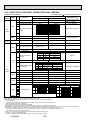
10-8. FUNCTION OF SWITCHES, CONNECTORS AND JUMPERS
(1) Function of switches
Type of
Switch No.
Switch
The black square ( ) indicates a switch position.
Action by the switch operation
ON
OFF
Function
1
Forced defrost *1
2
Abnormal history clear
Start
Clear
3
SW1
4
Dip
switch
5
Refrigerant address
setting
6
Off or operating
ON
ON
1 2 3 4 5 6
0
ON
1 2 3 4 5 6
1
ON
1 2 3 4 5 6
2
ON
1 2 3 4 5 6
3
1 2 3 4 5 6
4
1 2 3 4 5 6
5
When power supply ON
Test run
Operating
OFF
Heating
Cooling
Pump down
Start
Normal
Under suspension
1
No function
—
—
—
2
Power failure
automatic recovery *2
Auto recovery
No auto recovery
When power supply ON
3,4,5
No function
—
—
—
6
model select
2
3
5
Under suspension
Following SW5-6 reference
SW7-1
OFF
ON
OFF
Setting of demand
control
*3
SW7-2
OFF
OFF
ON
Power consumption
(Demand switch ON)
0% (Operation stop)
50%
75%
Always
—
—
—
No function
SW7
4
Dip
switch
Normal
ON
Test run mode setting
1
SW7
*4
When compressor is working
in heating operation. *1
2
SWP
SW5
Normal
1
SW4
Push
switch
Effective timing
4
OFF
OFF
ON
Breaker size setting
*Only SW75
Breaker size
Both for indoor unit Only for outdoor unit
5 and outdoor unit
25A (Default)
20A
OFF
16A
20A
ON
16A
—
ON
When power supply ON
6
Defrost setting
For high humidity
Normal
1
Use of existing pipe
Used
Not used
Always
Always
2
No function
—
—
—
3
No function
—
—
—
1
No function
—
—
—
SW9
2
Function switch
Valid
Normal
Always
No function
—
—
—
SW6
3,4
1
2
3
4
5
6
7
8
6
SW8
SW5
MODEL
75VHA
SW5-6
SW6
ON
OFF
ON
OFF
1 2 3 4 5 6
1 2 3 4 5 6 7 8
Model select
ON
OFF
ON
100VHA OFF
1 2 3 4 5 6 7 8
1 2 3 4 5 6
MODEL
SW5-6
SW6
ON
OFF
ON
120VHA OFF
1 2 3 4 5 6
1 2 3 4 5 6 7 8
ON
OFF
ON
100YHA OFF
1 2 3 4 5 6
1 2 3 4 5 6 7 8
ON
OFF
ON
120YHA OFF
1 2 3 4 5 6 7 8
1 2 3 4 5 6
w1 Forced defrost should be done as follows.
1Change the DIP SW1-1 on the outdoor controller board from OFF to ON.
2Forced defrost will start by the above operation 1 if all these conditions written below are satisfied.
• Heat mode setting
• 10 minutes have passed since compressor started operating or previous compulsory defrosting finished.
• Pipe temperature is less than or equal to 8:.
Forced defrost will finish if certain conditions are satisfied.
Forced defrost can be done if above conditions are satisfied when DIP SW1-1 is changed from OFF to ON.
After DIP SW1-1 is changed from OFF to ON, there is no problem if DIP SW1-1 is left ON or changed to OFF again. This depends on the service conditions.
w2 ‘Power failure automatic recovery’ can be set by either remote controller or this DIP SW. If one of them is set to ON,
‘Auto recovery’ activates. Please set “Auto recovery” basically by remote controller because all units do not have DIP SW.
Please refer to the indoor unit installation manual.
w3 SW7-1,2 are used for demand control. SW7-1,2 are effective only at the demand control.
(Refer to next page : Special function (b))
w4 Please do not use SW7-3~6 usually. Trouble might be caused by the usage condition.
OCH533A
52
(2) Function of connector
Types
Connector
Function
Connector
CN31
Emergency operation
Action by open/ short operation
Short
Open
Start
Normal
Effective timing
When power supply ON
Special function
(a) Low-level sound priority mode (Local wiring)
Unit enters into Low-level sound priority mode by external signal input setting.
Inputting external signals to the outdoor unit decreases the outdoor unit operation sound 3 to 4 dB lower than that of usual.
Adding a commercial timer or on-off switch contactor setting to the CNDM connector which is optional contactor for demand
input located on the outdoor controller board enables to control compressor operation frequency.
W The performance depends on the load of conditioned outdoor temperature.
How to wire
<Low-level sound priority mode circuit>
Insulate this point securely as
this is not used.
Purchased locally
Adaptor for external
signal input
(PAC-SC36NA)
Red 3
Brown 2
Orange 1
Relay
supply
~ SW1
X
CNDM
X
SW1 : Switch
X : Relay (Contact spec. : DC1mA)
Outdoor unit
controller board
Max. 10 m including local wiring
1) Make the circuit as shown above with Adaptor for external signal input (PAC-SC36NA).
2) Turn SW1 to on for Low-level sound priority mode.
Turn SW1 to off to release Low-level sound priority mode and normal operation.
(b) On demand control (Local wiring)
Demand control is available by external input. In this mode, power consumption is decreased within the range of usual
0~100%.
How to wire
Basically, the wiring is the same as (a).
Connect an SW 1 which is procured at field to the between Orange and Red (1 and 3) of the Adaptor for external signal
input (PAC-SC36NA), and insulate the tip of the brown lead wire.
It is possible to set it to the following power consumption (compared with ratings) by setting the SW7-1, 2.
SW7-1
SW7-2
Power consumption
(SW1 on)
OFF
OFF
0% (Operation stop)
ON
OFF
50%
OFF
ON
75%
OCH533A
53
<Display function of inspection for outdoor unit>
The blinking patterns of both LED1 (green) and LED2 (red) indicate the types of abnormality when it occurs. Types of abnormality can be indicated in details by connecting an optional part “A-Control Service Tool (PAC-SK52ST)” to connector CNM on
outdoor controller board.
[Display]
(1)Normal condition
Unit condition
When the power is turned on
When unit stops
When compressor is warming up
When unit operates
Outdoor controller board
A-Control Service Tool
LED1 (Green)
LED2 (Red)
Lighted
Lighted
Lighted
Lighted
Lighted
Not lighted
Not lighted
Lighted
Indication of the display
Error code
00, etc.
08, etc.
C5, H7 etc.
Alternately blinking display
Operation mode
(2)Abnormal condition
Indication
Outdoor controller board
LED1 (Green) LED2 (Red)
Error
Contents
1 blinking 2 blinking Connector(63L) is open.
Connector(63H) is open.
2 connectors are open.
2 blinking 1 blinking Miswiring of I/F or FTC or outdoor unit
Error
code
+1
Inspection method
F3
F5
F9
—
Check if connector (63H or 63L) on the outdoor controller
board is not disconnected.
Check continuity of pressure switch (63H or 63L) by tester.
E0
Check if connecting wire of I/F or FTC unit or remote controller
is connected correctly.
Check if noise entered into transmission wire of remote
controller.
Re-check error by turning off power, and on again.
Check if I/F or FTC or outdoor connecting wire is connected
correctly.
Check
if 4 or more I/F or FTC units are connected to
—
outdoor unit.
Check if noise entered into I/F or FTC or outdoor connecting
wire or power supply.
Startup time over
— Re-check error by turning off power, and on again.
2 blinking I/F or FTC or outdoor unit communication E6 Check if I/F or FTC or outdoor connecting wire is connected
error (signal receiving error) is detected by
correctly.
FTC unit.
I/F or FTC or outdoor unit communication
— Check if noise entered into I/F or FTC or outdoor connecting
wire or power supply.
error (signal receiving error) is detected by
(E8) Check if noise entered into I/F or FTC or outdoor controller
outdoor unit.
—
I/F or FTC or outdoor unit communication
board.
error (transmitting error) is detected by
(E9)
Re-check error by turning off power, and on again.
outdoor unit.
connecting wire, excessive number of
indoor units (4 units or more)
Miswiring of I/F or FTC or outdoor unit
connecting wire (converse wiring or
disconnection)
3 blinking Remote controller signal receiving
error is detected by remote controller.
Remote controller transmitting error
is detected by remote controller.
E3
Remote controller signal receiving
error is detected by I/F or FTC unit.
E4
Remote controller transmitting error
is detected by I/F or FTC unit.
E5
4 blinking Error code is not defined.
EF
Check if noise entered into transmission wire of remote
controller.
Check if noise entered into I/F or FTC or outdoor connecting
wire.
Re-check error by turning off power, and on again.
1 Error code displayed on remote controller
2 Refer to Technical manual of ATW, I/F, FTC.
OCH533A
54
Indication
Outdoor controller board
LED1 (Green) LED2 (Red)
Contents
3 blinking 1 blinking Abnormality of comp. surface
thermistor(TH34) and discharging
temperature (TH4)
Abnormality of superheat due
to low discharge temperature
Error
Error
Inspection method
code
+1
U2 Check if stop valves are open.
Check if connectors (TH4, TH34, LEV-A, and LEV-B) on outdoor controller
board are not disconnected.
Check if unit is filled with specified amount of refrigerant.
Measure resistance values among terminals on indoor valve and
U7
outdoor linear expansion valve using a tester.
Detailed
reference
page
P.24
P.25
2 blinking Abnormal high pressure (High U1 Check if indoor/outdoor units have a short cycle on their air ducts.
P.24
Check if connector (63H/63L) on outdoor controller board is not disconnected.
pressure switch 63H operated.)
Check if heat exchanger and filter is not dirty.
UL Measure resistance values among terminals on linear expansion valve
Abnormal low pressure (Low
using a tester.
P.27
pressure switch 63L operated.)
3 blinking Abnormality of outdoor fan
motor rotational speed
Protection from overheat operation(TH3)
4 blinking Compressor overcurrent
breaking(Start-up locked)
Compressor overcurrent breaking
Abnormality of current sensor (P.B.)
Abnormality of power module
5 blinking Open/short of discharge thermistor (TH4)
and comp. surface thermistor (TH34)
U8 Check the outdoor fan motor.
P.25
Ud
UF Check if stop valves are open.
P.27
UH
U6
U3 Check if connectors(TH3,TH4,TH6 ,TH7 and TH34)on outdoor controller
P.28
P.27
P.25
P.24
Check if connector (TH3) on outdoor controller board is disconnected.
Check looseness, disconnection, and converse connection of
compressor wiring.
resistance values among terminals on compressor using a tester.
UP Measure
Check if outdoor unit has a short cycle on its air duct.
board and connector (CN3) on outdoor power board are not disconnected.
Measure resistance value of outdoor thermistors.
Open/short of outdoor thermistors U4
(TH3, TH6, TH7 and TH8)
6 blinking Abnormality of heatsink
temperature
7 blinking Abnormality of voltage
4 blinking 1 blinking Abnormality of room temperature thermistor (TH1)
Abnormality of pipe temperature thermistor /Liquid (TH2)
Abnormality of pipe temperature
thermistor/Condenser-Evaporator
2 blinking Abnormality of drain sensor (DS)
Float switch(FS) connector open
P.25
U5 Check if indoor/outdoor units have a short cycle on their air ducts.
P.25
U9 Check looseness, disconnection, and converse connection of
P.26
Measure resistance value of outdoor thermistor(TH8).
compressor wiring.
Measure resistance value among terminals on compressor using a tester.
Check the continuity of contactor (52C).
Check if power supply voltage decreases.
Check the wiring of CN52C.
Check the wiring of CNAF.
P1 Check if connectors (CN20, CN21, CN29 and CN44) on indoor
controller board are not disconnected.
P2 Measure resistance value of indoor thermistors.
P9
2
2
2
P4 Check if connector (CN31)(CN4F) on indoor controller board is not
2
disconnected.
Measure resistance value of indoor thermistors.
resistance value among terminals on drain-up machine using
Indoor drain overflow protection P5 Measure
a tester.
Check if drain-up machine works.
Check drain function.
3 blinking Freezing (cooling)/overheating P6 Check if indoor unit has a short cycle on its air duct.
Check if heat exchanger and filter is not dirty.
(heating) protection
Measure resistance value on indoor and outdoor fan motors.
2
4 blinking Abnormality of pipe
temperature
2
Check if the inside of refrigerant piping is not clogged.
P8 Check if indoor thermistors(TH2 and TH5) are not disconnected from holder.
Check if stop valve is open.
Check converse connection of extension pipe. (on plural units connection)
Check if indoor/outdoor connecting wire is connected correctly.
(on plural units connection)
1 Error code displayed on remote controller
2 Refer to service manual for indoor unit.
OCH533A
55
<Outdoor unit operation monitor function>
[When optional part ‘A-Control Service Tool (PAC-SK52ST)’ is connected to outdoor controller board (CNM)]
Digital indicator LED1 displays 2 digit number or code to inform operation condition and the meaning of error code by
controlling DIP SW2 on ‘A-Control Service Tool’.
Operation indicator
SW2 : Indicator change of self diagnosis
Unit
Explanation for display
Display detail
SW2 setting
ON
1 2 3 4 5 6
<Digital indicator LED1 working details>
(Be sure that the 1 to 6 in the SW2 are set to OFF.)
(1) Display when the power supply ON
When the power supply ON, blinking displays by turns.
Wait for 4 minutes at the longest.
(2) When the display lights (Normal operation)
1Operation mode display.
1 second
interval
(Lighting)
SW2
LED1
ON
(Initial setting)
1 2 3 4 5 6
The ones digit : Relay output
The tens digit : Operation mode
Display
Operation Model
O
C
H
d
OFF / FAN
COOLING / DRY +
HEATING
DEFROSTING
*C5 is displayed during replacement operation.
2Display during error postponement
Postponement code is displayed when
compressor stops due to the work of
protection device.
Postponement code is displayed while
error is being postponed.
Display
Warming-up
Compressor
Compressor
4-way valve
Solenoid valve
0
1
2
3
4
5
6
7
8
A
—
—
—
—
—
—
—
—
ON
ON
—
—
—
—
ON
ON
ON
ON
—
—
—
—
ON
ON
—
—
ON
ON
—
ON
—
ON
—
ON
—
ON
—
ON
—
—
(3) When the display blinks
Inspection code is displayed when compressor stops due to the work of protection devices.
Display
0
1
2
3
Display
F3
F5
F9
E8
E9
EA
Eb
EC
E0~E7
Inspection unit
Outdoor unit
Indoor unit 1
Indoor unit 2
Indoor unit 3
Display
U1
U2
U3
U4
U5
U6
U7
U8
Ud
UF
UH
UL
UP
P1~P8
A0~A7
Contents to be inspected (During operation)
Abnormal high pressure (63H worked)
Abnormal high discharging temperature and shell thermistor, shortage of refrigerant
Open/short circuit of discharging thermistor(TH4) and comp. surface thermistor(TH34)
Open/short of outdoor unit thermistors(TH3, TH6, TH7 and TH8)
Abnormal temperature of heatsink
Abnormality of power module
Abnormality of superheat due to low discharge temperature
Abnormality in outdoor fan motor
Overheat protection
Compressor overcurrent interruption (When Comp. locked)
Current sensor error
Abnormal low pressure
Compressor overcurrent interruption
Abnormality of indoor units
Communication error of M-NET system
Contents to be inspected (When power is turned on)
63L connector(red) is open.
63H connector(yellow) is open.
2 connectors(63H/63L) are open.
Indoor/outdoor communication error (Signal receiving error) (Outdoor unit)
Indoor/outdoor communication error (Transmitting error) (Outdoor unit)
Miswiring of indoor/outdoor unit connecting wire, excessive number of indoor units (4 units or more)
Miswiring of indoor/outdoor unit connecting wire(converse wiring or disconnection)
Startup time over
Communication error except for outdoor unit
OCH533A
56
The black square ( ) indicates a switch position.
SW2 setting
ON
Explanation for display
Display detail
Pipe temperature / Liquid (TH3)
-40 – 90
-40 – 90
(When the coil thermistor detects 0: or below, “–”
and temperature are displayed by turns.)
(Example) When -10:;
0.5 secs. 0.5secs. 2 secs.
1 2 3 4 5 6
Unit
:
10
Discharge temperature (TH4)
3 – 217
3 – 217
(When the discharge thermistor detects 100: or
more, hundreds digit, tens digit and ones digit are
displayed by turns.)
(Example) When 105:;
0.5 secs. 0.5secs. 2 secs.
1
05
ON
1 2 3 4 5 6
ON
:
Output step of outdoor FAN
0 – 10
0 – 10
The number of ON / OFF times of compressor
0 – 9999
0 – 9999
(When the number of times is 100 or more,
hundreds digit, tens digit and ones digit are
displayed by turns.)
(Example) When 42500 times (425 ×100 times);
0.5 secs. 0.5secs. 2 secs.
4
25
100 times
0 – 9999
(When it is 100 hours or more, hundreds digit, tens
digit and ones digit are displayed by turns.)
(Example) When 2450 hours (245 ×10 hours);
0.5 secs. 0.5secs. 2 secs.
2
45
10 hours
Step
1 2 3 4 5 6
ON
1 2 3 4 5 6
ON
Compressor integrating operation times
0 – 9999
1 2 3 4 5 6
ON
Compressor operating current
0 – 50
0 – 50
wOmit the figures after the decimal fractions.
Compressor operating frequency
0 – 255
0 – 255
(When it is 100Hz or more, hundreds digit, tens
digit and ones digit are displayed by turns.
(Example) When 125Hz;
0.5 secs. 0.5secs. 2 secs.
1
25
Hz
0 – 480
(When it is 100 pulse or more, hundreds digit, tens
digit and ones digit are displayed by turns.
(Example) When 150 pulse;
0.5 secs. 0.5secs. 2 secs.
1
50
Pulse
A
1 2 3 4 5 6
ON
1 2 3 4 5 6
ON
LEV-A opening pulse
0 – 480
1 2 3 4 5 6
ON
Error postponement code history (1)
of outdoor unit
Postponement code display
Blinking: During postponement
Lighting: Cancellation of postponement
“00” is displayed in case of no postponement.
Operation mode on error occurring
Operation mode of when operation stops due to
error is displayed by setting SW2 like below.
1 2 3 4 5 6
ON
(SW2)
ON
1 2 3 4 5 6
1 2 3 4 5 6
OCH533A
57
Code
display
Code
display
The black square ( ) indicates a switch position.
Display detail
Explanation for display
Unit
Pipe temperature/Liquid (TH3) on error
occurring
-40 – 90
-40 – 90
(When the coil thermistor detects 0: or below, “–”
and temperature are displayed by turns.)
(Example) When –15:;
0.5 secs. 0.5secs. 2 secs.
15
:
Compressor temperature (TH4) or
discharge temperature (TH4) on error
occurring
3 – 217
3 – 217
(When the temperature is 100: or more, the
hundreds digit, tens digit and ones digit are
displayed by turns.)
(Example) When 130:;
0.5 secs. 0.5secs. 2 secs.
1
30
:
Compressor operating current on error
occurring
0 – 50
0 – 50
SW2 setting
ON
1 2 3 4 5 6
ON
1 2 3 4 5 6
ON
A
1 2 3 4 5 6
ON
Error code history (1) (latest)
Alternate display of abnormal unit
number and code
When no error history,
“ 0 ” and “– –” are displayed by turns.
Error code history (2)
Alternate display of error unit number
and code
When no error history,
“ 0 ” and “– –” are displayed by turns.
Thermostat ON time
0 – 999
0 – 999
(When it is 100 minutes or more, the hundreds digit,
tens digit and ones digit are displayed by turns.)
(Example) When 245 minutes;
0.5 secs. 0.5secs. 2 secs.
2
45
Code
display
1 2 3 4 5 6
ON
Code
display
1 2 3 4 5 6
ON
1 2 3 4 5 6
Test run elapsed time
0 – 120
OCH533A
0 – 120
(When it is 100 minutes or more, the hundreds digit,
tens digit and ones digit are displayed by turns.)
(Example) When 105 minutes;
0.5 secs. 0.5secs. 2 secs.
1
05
58
Minute
Minute
The black square ( ) indicates a switch position.
SW2 setting
Explanation for display
Display detail
The number of connected indoor units
ON
0–3
(The number of connected indoor units are displayed.)
Unit
Unit
1 2 3 4 5 6
Capacity setting display
Displayed as an outdoor capacity code.
Capacity
SW75V
SW100V, 100Y
SW120V, 120Y
ON
1 2 3 4 5 6
Outdoor unit setting information
Code
14
20
25
Code
display
• The tens digit (Total display for applied setting)
Setting details
Display details
H·P / Cooling only
0 : H·P
1 : Cooling only
Single phase / 3 phase
0 : Single phase 2 : 3 phase
ON
• The ones digit
Setting details
1 2 3 4 5 6
Display details
Defrosting switch 0 : Normal
Code
display
1 : For high humidity
(Example) When heat pump, 3 phase and defrosting
(normal) are set up, “20” is displayed.
ON
Indoor pipe temperature / Liquid (TH2(1)) -39 – 88
(When the temperature is 0: or less, “–” and
Indoor 1
temperature are displayed by turns.)
-39 – 88
:
Indoor pipe temperature / Cond./Eva.
(TH5(1))
Indoor 1
-39 – 88
:
1 2 3 4 5 6
ON
-39 – 88
(When the temperature is 0: or less, “–” and
temperature are displayed by turns.)
1 2 3 4 5 6
ON
Indoor pipe temperature / Liquid (TH2(2)) -39 – 88
Indoor 2
(When the temperature is 0: or less, “–” and
-39 – 88
temperature are displayed by turns.)
:
1 2 3 4 5 6
ON
Indoor pipe temperature / Cond./Eva.
(TH5(2))
Indoor 2
-39 – 88
-39 – 88
(When the temperature is 0: or less, “–” and
temperature are displayed by turns.)
Indoor room temperature (TH1)
8 – 39
8 – 39
:
1 2 3 4 5 6
ON
:
1 2 3 4 5 6
OCH533A
59
The black square ( ) indicates a switch position.
Display detail
SW2 setting
ON
Unit
Explanation for display
Indoor setting temperature
17 – 30
17 – 30
Pressure saturation temperature (T63HS)
-39 – 88
-39 – 88
(When the temperature is 0: or less, “–” and
temperature are displayed by turns.)
:
Ambient temperature (TH7)
-39 – 88
-39 – 88
(When the temperature is 0: or less, “–” and
temperature are displayed by turns.)
:
:
1 2 3 4 5 6
ON
1 2 3 4 5 6
ON
1 2 3 4 5 6
Outdoor heatsink temperature (TH8)
-40 – 200
ON
1 2 3 4 5 6
Discharge superheat SHd
0 – 255
ON
1 2 3 4 5 6
Cooling = TH4 - T63HS
Heating = TH4 - T63HS
Sub cool. SC
0 – 130
ON
Cooling = T63HS - TH3
Heating = T63HS - TH2
1 2 3 4 5 6
Input current of outdoor unit
ON
-40 – 200
(When the temperature is 0: or less, “–” and
temperature are displayed by turns.)
(When the thermistor detects 100: or more,
hundreds digit, tens digit and ones digit are
displayed by turns.)
0 – 255
(When the temperature is 100°C or more, hundreds
digit, tens digit and ones digit are displayed by
turns.)
0 – FFFE (in hexadecimal notation)
(When more than FF in hex (255 in decimal), the
number is displayed in order of 163's and 162's, and
161's and 160's places.
(Example) When 5000 cycles;
0.5 secs. 0.5 secs. 2 secs.
9
C4
0 – 500
(When it is 100 or more, hundreds digit, tens digit
and ones digit are displayed by turns.)
:
°C
2 cycles
0.1 A
1 2 3 4 5 6
LEV-B opening pulse
ON
0 – 480
(When it is 100 pulse or more, hundreds digit, tens
digit and ones digit are displayed by turns.)
Pulse
1 2 3 4 5 6
U9 error detail history (latest)
Description
ON
1 2 3 4 5 6
(No error)
Overvoltage error
Undervoltage error
Input current sensor error
L1-phase open error
Abnormal power synchronous signal
PFC error (SW75VHA)
(Overvoltage / Undervoltage / Overcurrent)
PFC/ IGBT error (SW·VHA)
(Undervoltage)
Display
00
01
02
04
08
10
20
* Display examples for multiple errors:
Overvoltage (01) + Undervoltage (02) = 03
Undervoltage (02) + Power-sync signal error (08) = 0A
L1 phase open error (04) + PFC error (10) = 14
OCH533A
60
Code
display
The black square ( ) indicates a switch position.
SW2 setting
ON
Explanation for display
Display detail
Unit
DC bus voltage
180 – 370 (SW75/100/120V)
300 – 750 (SW100/120Y)
180 – 370 (SW75/100/120V)
300 – 750 (SW100/120Y)
(When it is 100V or more, hundreds digit, tens
digit and ones digit are displayed by turns.)
V
Error postponement code history (2)
of outdoor unit
Postponement code display
Blinking: During postponement
Lighting: Cancellation of postponement
“00” is displayed in case of no postponement.
Code
display
Postponement code display
Blinking: During postponement
Lighting: Cancellation of postponement
“00” is displayed in case of no postponement.
Code
display
1 2 3 4 5 6
ON
1 2 3 4 5 6
Error postponement code history (3)
of outdoor unit
ON
1 2 3 4 5 6
ON
When no error history, “0” and “– –“ are displayed by
turns.
Error code history (3) (Oldest)
Alternate display of abnormal unit
number and code.
Code
display
1 2 3 4 5 6
3: Outdoor pipe temperature/Liquid (TH3)
4: Discharge thermistor (TH4)
6: 2-phase pipe (TH6)
7: Ambient temperature (TH7)
8: Outdoor heatsink (TH8)
34: Comp. surface thermistor (TH34)
Error thermistor display
ON
When there is no error thermistor,
“–“ is displayed.
1 2 3 4 5 6
Operation frequency on error occurring
0 – 255
ON
0 – 255
(When it is 100Hz or more, hundreds digit, tens digit
and ones digit are displayed by turns.)
(Example) When 125Hz;
0.5 secs. 0.5secs. 2 secs.
1
25
Hz
1 2 3 4 5 6
ON
Code
display
Fan step on error occurring
0 – 10
0 – 10
Step
1 2 3 4 5 6
OCH533A
61
The black square ( ) indicates a switch position.
Display detail
Explanation for display
LEV-A opening pulse on error occurring
0 – 480
0 – 480
(When it is 100 pulse or more, hundreds digit, tens
digit and ones digit are displayed by turns.)
(Example) When 130 pulse;
0.5 secs. 0.5secs. 2 secs.
1
30
SW2 setting
ON
1 2 3 4 5 6
Indoor room temperature (TH1) on error
occurring
8 – 39
ON
Unit
Pulse
8 – 39
:
1 2 3 4 5 6
Indoor pipe temperature / Liquid (TH2)
on error occurring
-39 – 88
ON
1 2 3 4 5 6
Pressure saturation temperature (T63HS)
on error occurring
ON
1 2 3 4 5 6
2-phase pipe (TH6) on error occurring
-39 – 88
ON
1 2 3 4 5 6
Ambient temperature (TH7) on error
occurring
-39 – 88
ON
1 2 3 4 5 6
Outdoor heatsink temperature (TH8) on
error occurring
-40 – 200
ON
1 2 3 4 5 6
OCH533A
-39 – 88
(When the temperature is 0°C or less, “–” and
temperature are displayed by turns.)
(Example) When –15°C;
0.5 secs. 0.5secs. 2 secs.
15
-39 – 88
(When the temperature is 0°C or less, “–” and
temperature are displayed by turns.)
(Example) When –15°C;
0.5 secs. 0.5secs. 2 secs.
15
-39 – 88
(When the temperature is 0°C or less, “–” and
temperature are displayed by turns.)
(Example) When –15°C;
0.5 secs. 0.5secs. 2 secs.
15
-39 – 88
(When the temperature is 0°C or less, “–” and
temperature are displayed by turns.)
(Example) When –15°C;
0.5 secs. 0.5secs. 2 secs.
15
-40 – 200
(When the temperature is 0°C or less, “–” and
temperature are displayed by turns.)
(When the temperature is 100°C or more, hundreds
digit, tens digit and ones digit are displayed by
turns.)
62
:
:
:
:
:
The black square ( ) indicates a switch position.
SW2 setting
Display detail
Explanation for display
Unit
Discharge superheat on error occurring
SHd
0 – 255
0 – 255
(When the temperature is 100°C or more, hundreds
digit, tens digit and ones digit are displayed by
turns.)
(Example) When 150°C;
0.5 secs. 0.5secs. 2 secs.
1
50
:
ON
1 2 3 4 5 6
Cooling = TH4 - T63HS
Heating = TH4 - T63HS
0 – 130
(When the temperature is 100°C or more, hundreds
digit, tens digit and ones digit are displayed by
turns.)
(Example) When 115°C;
0.5 secs. 0.5secs. 2 secs.
1
15
Sub cool on error occurring SC
0 – 130
ON
Cooling = T63HS - TH3
Heating = T63HS - TH2
1 2 3 4 5 6
0 – 999
(When it is 100 minutes or more, hundreds digit, tens
digit and ones digit are displayed by turns.)
(Example) When 415 minutes;
0.5 secs. 0.5secs. 2 secs.
Thermo-on time until error stops
0 – 999
ON
:
Minute
1 2 3 4 5 6
4
ON
1 2 3 4 5 6
ON
15
Indoor pipe temperature / Liquid
(TH2 (3))
Indoor 3
-39 – 88
-39 – 88
(When the temperature is 0°C or less, “–” and
temperature are displayed by turns.)
Indoor pipe temperature / Cond./Eva.
(TH5 (3))
Indoor 3
-39 – 88
-39 – 88
(When the temperature is 0°C or less, “–” and
temperature are displayed by turns.)
1 2 3 4 5 6
:
:
When there is no indoor unit, “00” is displayed.
Controlling status of compressor
operating frequency
The following code will be a help to know the
operating status of unit.
•The tens digit
Display Compressor operating frequency control
1
Primary current control
Secondary current control
2
•The ones digit (In this digit, the total number of
activated control is displayed.)
Display Compressor operating frequency control
Preventive control for excessive temp1
erature rise of discharge temperature
Preventive control for excessive temp2
erature rise of condensing temperature
4
Frosting preventing control
Preventive control for excessive temp8
erature rise of heatsink
(Example)
The following controls are activated.
LED
• Primary current control
• Preventive control for excessive temperature rise of condensing temperature
• Preventive control for excessive temperature rise of heatsink
ON
1 2 3 4 5 6
OCH533A
63
Code
display
The black square ( ) indicates a switch position.
Comp. surface temperature (TH34)
3 – 217
ON
1 2 3 4 5 6
3 – 217
(When the comp.shell thermistor detects 100°C or
more, hundreds digit, tens digit and ones digit are
displayed by turns.)
(Example) When 105°C;
0.5 secs. 0.5secs. 2 secs.
1
U9 Error details (To be shown while
error call is deferred.)
ON
1 2 3 4 5 6
Unit
Explanation for display
Display detail
SW2 setting
Description
(No error)
Overvoltage error
Undervoltage error
Input current sensor error
L1-phase open error
Abnormal power synchronous signal
PFC error (SW75VHA)
(Overvoltage / Undervoltage / Overcurrent)
PFC/ IGBT error (SW·VHA)
(Undervoltage)
05
Display
00
01
02
* Display examples for multiple errors:
Overvoltage (01) + Undervoltage (02) = 03
Undervoltage (02) + Power-sync signal error (08) = 0A
L1 phase open error (04) + PFC error (10) = 14
OCH533A
64
:
04
08
10
20
Code
display
11
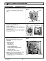
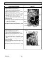
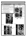
DISASSEMBLY PROCEDURE
PUHZ-SW75VHA.UK
PUHZ-SW75VHA-BS.UK
PHOTOS & ILLUSTRATION
OPERATING PROCEDURE
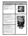
1. Removing the service panel and top panel
(1) Remove 3 service panel fixing screws (5 × 12) and slide
the hook on the right downward to remove the service
panel.
(2) Remove screws (3 for front, 3 for rear/5 × 12) of the top
panel and remove it.
Photo 1
Top panel fixing screws
Top panel
Slide
Service panel
Fan grille
Grille fixing screws
Service panel
fixing screws
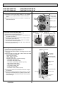
2. Removing the fan motor (MF1)
Photo 2-1
Photo 2-2
(1) Remove the service panel. (See Photo 1)
(2) Remove the top panel. (See Photo 1)
Front panel
Propeller
Fan motor fixing screws
(3) Remove 5 fan grille fixing screws (5 × 12) to detach the
fan grille. (See Photo 1)
(4) Remove a nut (for right handed screw of M6) to detach the
propeller. (See Photo 2-1)
(5) Disconnect the connector CNF1 on controller circuit board
in electrical parts box.
(6) Remove 4 fan motor fixing screws (5 × 20) to detach the
Nut
fan motor. (See Photo 2-2)
Front panel fixing screws
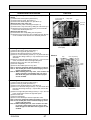
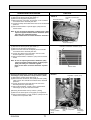
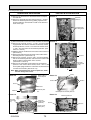
3. Removing the electrical parts box
(1) Remove the service panel. (See Photo 1)
(2) Remove the top panel. (See Photo 1)
(3) Disconnect the indoor/outdoor connecting wire from
terminal block.
(4) Disconnect the connector CNF1, LEV-A and LEV-B on the
controller circuit board.
<Symbols on the board>
• CNF1 : Fan motor
• LEV-A, LEV-B : LEV
(5) Disconnect the pipe-side connections of the following parts.
• Thermistor <Liquid> (TH3)
• Thermistor <Discharge> (TH4)
• Thermistor <Ambient, 2-phase pipe> (TH7/6)
• Thermistor <Heatsink> (TH8)
• High pressure switch (63H)
• 4-way valve coil (21S4)
• Thermistor <Comp. surface> (TH34)
(5) Remove the terminal cover and disconnect the compressor
lead wire.
(6) Remove an electrical parts box fixing screw (4 × 10) and
detach the electrical parts box by pulling it upward.
The electrical parts box is fixed with 2 hooks on the left
and 1 hook on the right.
OCH533A
65
Fan
motor
(MF1)
Fan motor
fixing screw
Photo 3
Electrical parts box
Terminal block
(TB1)
Controller circuit
board (C.B.)
Electrical parts
box fixing screws
OPERATING PROCEDURE
PHOTOS
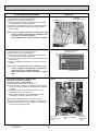
4. Removing the thermistor <2-phase pipe> (TH6)
(1) Remove the service panel. (See Photo 1)
(2) Remove the top panel. (See Photo 1)
(3) Disconnect the connector TH7/6 (red) on the controller
circuit board in the electrical parts box.
(4) Loosen the clamp for the lead wire in the rear of the
electrical parts box.
(5) Pull out the thermistor <2-phase pipe> (TH6) from the
sensor holder.
Photo 4
Electrical parts box
Thermistor
<2-phase pipe> (TH6)
Clamp
Note: In case of replacing thermistor <2-phase pipe> (TH6),
replace it together with thermistor <Ambient> (TH7),
since they are combined together.
Refer to No.5 below to remove thermistor <Ambient>.
Controller circuit board (C.B.)
5. Removing the thermistor <Ambient> (TH7)
(1) Remove the service panel. (See Photo 1)
(2) Remove the top panel. (See Photo 1)
(3) Disconnect the connector TH7/6 (red) on the controller
circuit board in the electrical parts box.
(4) Loosen the clamp for the lead wire in the rear of the
electrical parts box. (See Photo 4)
(5) Pull out the thermistor <Ambient> (TH7) from the sensor
holder.
Photo 5
Lead wire of thermistor <Ambient> (TH7)
Note: In case of replacing thermistor <Ambient> (TH7),
replace it together with thermistor <2-phase pipe>
(TH6), since they are combined together.
Refer to No.4 above to remove thermistor <2-phase
pipe>.
Sensor holder
6. Removing the thermistor <Liquid> (TH3) and thermistor
<Discharge> (TH4), thermistor <Comp. surface> (TH34)
(1) Remove the service panel. (See Photo 1)
(2) Disconnect the connectors, TH3 (white) and TH4 (white),
TH34 (red) on the controller circuit board in the electrical
parts box.
(3) Loosen the clamp for the lead wire in the rear of the electrical parts box. (See Photo 4)
(4) Pull out the thermistor <Liquid> (TH3) and thermistor
<Discharge> (TH4) from the sensor holder.
Photo 6
Liquid thermistor
(TH3)
[Removing the thermistor<Comp. surface> (TH34)]
(5) Remove the compressor cover (upper) and pull out the
thermistor <Comp. surface> (TH34) from the holder of the
compressor Comp.surface.
Comp. surface
thermistor (TH34)
OCH533A
66
Dischage
thermistor (TH4)
PHOTOS
OPERATING PROCEDURE
7. Removing the 4-way valve coil (21S4), LEV coil (LEV-A,
LEV-B)
(1) Remove the service panel. (See Photo 1)
(2) Remove the top panel. (See Photo 1)
(3) Remove the electrical parts box. (See Photo 3)
[Removing the 4-way valve coil]
(4) Remove 4-way valve coil fixing screw (M5 × 6).
(5) Remove the 4-way valve coil by sliding the coil toward you.
(6) Disconnect the connector 21S4 (green) on the controller
board in the electrical parts box.
[Removing the LEV coil]
(4) Remove the LEV coil by sliding the coil upward.
(5) Disconnect the connectors, LEV A (white) and LEV B (red),
on the controller circuit board in the electrical parts box.
Photo 7
4-way valve coil
fixing screw
4-way valve
LEV
LEV coil
(LEV B)
High pressure
switch (63H)
8. Removing the 4-way valve
(1) Remove the service panel. (See Photo 1)
(2) Remove the top panel. (See Photo 1)
(3) Remove the electrical parts box. (See Photo 3)
(4) Remove 3 valve bed fixing screws (4 × 10) and 4 ball valve
Photo 8
and stop valve fixing screws (5 × 16) and then remove the
valve bed.
(5) Remove 3 right side panel fixing screws (5 × 12) in the rear
of the unit and then remove the right side panel.
(6) Remove the 4-way valve coil. (See Photo 7)
(7) Recover refrigerant.
LEV coil
(8) Remove the welded part of 4-way valve.
Note 1: Recover refrigerant without spreading it in the air. (LEV B)
Note 2: The welded part can be removed easily by removing the right side panel.
Note 3: When installing the 4-way valve, cover it with a wet
cloth to prevent it from heating (120°C or more),
then braze the pipes so that the inside of pipes
are not oxidized.
9. Removing the LEV
(1) Remove the service panel. (See Photo 1)
(2) Remove the top panel. (See Photo 1)
(3) Remove the electrical parts box. (See Photo 3)
(4) Remove 3 valve bed fixing screws (4 × 10) and 4 ball valve
and stop valve fixing screws (5 × 16) and then remove the
valve bed.
(5) Remove 3 right side panel fixing screws (5 × 12) in the rear
of the unit and then remove the right side panel.
(6) Remove the LEV.
(7) Recover refrigerant.
(8) Remove the welded part of linear expansion valve.
Note 1: Recover refrigerant without spreading it in the air.
Note 2: The welded part can be removed easily by removing the right side panel.
Note 3: When installing the LEV, cover it with a wet cloth
to prevent it from heating (120°C or more), then
braze the pipes so that the inside of pipes are not
oxidized.
OCH533A
67
Valve bed
LEV
LEV coil (LEV A)
4-way
valve
Valve bed
fixing screws
OPERATING PROCEDURE
PHOTOS
10. Removing the high pressure switch (63H)
(1) Remove the service panel. (See Photo 1)
(2) Remove the top panel. (See Photo 1)
(3) Remove the electrical parts box. (See Photo 3)
(4) Remove 3 right side panel fixing screws (5 × 12) in the
rear of the unit and remove the right side panel.
(5) Pull out the lead wire of high pressure switch.
(6) Recover refrigerant.
(7) Remove the welded part of high pressure switch.
Photo 9
Lead wire of
high pressure switch
Note 1: Recover refrigerant without spreading it in the air.
Note 2: The welded part can be removed easily by
removing the right side panel.
Note 3: When installing the high pressure switch, cover it
with a wet cloth to prevent it from heating (100°C
or more), then braze the pipes so that the inside
of pipes are not oxidized.
High pressure switch (63H)
11. Removing the reactor (ACL)
(1) Remove the service panel. (See Photo 1)
(2) Remove the top panel. (See Photo 1)
(3) Remove the electrical parts box. (See Photo 3)
(4) Remove 4 reactor fixing screws (4 × 20) and remove the
reactor.
* The reactor is attached to the rear of the electrical parts box.
Photo 10
Reactor fixing screws
Reactor
(ACL)
Reactor fixing screws
OCH533A
68
Electrical parts box
OPERATING PROCEDURE
PHOTOS
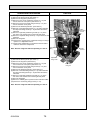
12. Removing the compressor (MC)
(1) Remove the service panel. (See Photo 1)
(2) Remove the top panel. (See Photo 1)
(3) Remove 2 front cover panel fixing screws (5 × 12) and
remove the front cover panel. (See Photo 2-1)
(4) Remove 2 back cover panel fixing screws (5 × 12) and
remove the back cover panel.
(5) Remove the electrical parts box. (See Photo 3)
(6) Remove 3 valve bed fixing screws (4 × 10) and 4 ball valve
and stop valve fixing screws (5 × 16) and then remove the
valve bed.
(7) Remove 3 right side panel fixing screws (5 × 12) in the
rear of the unit then remove the right side panel.
(8) Remove 3 separator fixing screws (4 × 10) and remove the
separator.
(9) Recover refrigerant.
(10) Remove the 3 points of the compressor fixing nut using a
spanner or a adjustable wrench.
(11) Remove the welded pipe of compressor inlet and outlet
then remove the compressor.
Note: Recover refrigerant without spreading it in the air.
Photo 11
Valve bed
fixing screw
Valve bed
Separator
Power
receiver
Compressor
fixing nut
Separator
fixing screw
Compressor
13. Removing the power receiver
(1) Remove the service panel. (See Photo 1)
(2) Remove the top panel. (See Photo 1)
(3) Remove 2 front cover panel fixing screws (5 × 12) and
remove the front cover panel. (See Photo 2-1)
(4) Remove 2 back cover panel fixing screws (5 × 12) and
remove the back cover panel.
(5) Remove the electrical parts box. (See Photo 3)
(6) Remove 3 valve bed fixing screws (4 × 10) and 4 ball valve
and stop valve fixing screws (5 × 16) then remove the valve
bed.
(7) Remove 3 right side panel fixing screws (5 × 12) in the
rear of the unit then remove the right side panel.
(8) Recover refrigerant.
(9) Remove 4 welded pipes of power receiver inlet and outlet.
(10) Remove 2 receiver leg fixing screws (4 × 10).
(See Photo 11)
Valve bed
fixing
screws
Compressor
fixing nut
Receiver leg
fixing screws
Receiver leg
Photo 12
Inlet
Note: Recover refrigerant without spreading it in the air.
Outlet
OCH533A
69
Power receiver
PUHZ-SW100VHA.UK
PUHZ-SW120VHA.UK
PUHZ-SW100VHA-BS.UK
PUHZ-SW120VHA-BS.UK
PHOTOS & ILLUSTRATION
OPERATING PROCEDURE
Photo 1
1. Removing the service panel and top panel
(1) Remove 3 service panel fixing screws (5 × 12) and slide
the hook on the right downward to remove the service
panel.
(2) Remove screws (3 for front, 3 for rear/5 × 12) of the top
panel and remove it.
Top panel fixing screws
Top panel
Service panel
fixing screws
Grille
fixing
screws
Service panel
Fan grille
Slide
Grille
fixing
screws
2. Removing the fan motor (MF1, MF2)
(1) Remove the service panel. (See Photo 1)
(2) Remove the top panel. (See Photo 1)
(3) Remove 5 fan grille fixing screws (5 × 12) to detach the
fan grille. (See Photo 1)
(4) Remove a nut (for right handed screw of M6) to detach
the propeller. (See Photo 2-1)
(5) Disconnect the connectors, CNF1, CNF2 on controller
circuit board in electrical parts box.
(6) Remove 4 fan motor fixing screws (5 × 20) to detach the
fan motor. (See Photo 2-2)
Service panel
fixing screws
Photo 2-1
Front panel Photo 2-2
Fan
Propeller
Fan motor fixing screws motor
Nut
Fan motor fixing screws
3. Removing the electrical parts box
(1) Remove the service panel. (See Photo 1)
(2) Remove the top panel. (See Photo 1)
(3) Disconnect the indoor/outdoor connecting wire from terminal block.
(4) Disconnect the connector CNF1, CNF2, LEV-A and LEV-B
on the controller circuit board.
<Symbols on the board>
• CNF1, CNF2 : Fan motor
• LEV-A, LEV-B : LEV
<Diagram symbol in the connector housing>
• Thermistor <Liquid> (TH3)
• Thermistor <Discharge> (TH4)
• Thermistor <2-phase pipe, Ambient> (TH6/7)
• High pressure switch (63H)
• High pressure sensor (63HS)
• Low pressure switch (63L)
• 4-way valve coil (21S4)
• Thermistor <Comp. surface> (TH34)
Photo 3
Controller circuit board
(C.B.)
Electrical
parts box
Electrical parts
box fixing screw
Terminal block
(TB1)
Valve bed
Compressor (MC)
(5) Remove the terminal cover and disconnect the compressor lead wire.
(6) Remove an electrical parts box fixing screw (4 × 10) and
detach the electrical parts box by pulling it upward. The
electrical parts box is fixed with 2 hooks on the left and 1
hook on the right.
Screw
Terminal cover
Cover panel
(Front)
Cover panel fixing screws
OCH533A
70
OPERATING PROCEDURE
PHOTOS
4. Removing the thermistor <2-phase pipe> (TH6)
(1) Remove the service panel. (See Photo 1)
(2) Remove the top panel. (See Photo 1)
(3) Disconnect the connectors, TH7/6 (red), on the controller
circuit board in the electrical parts box.
(4) Loosen the clamp for the lead wire in the rear of the electrical
parts box.
(5) Pull out the thermistor <2-phase pipe> (TH6) from the
sensor holder.
Photo 4
Electrical parts box
Thermistor <2-phase pipe>
(TH6)
Clamp
Note: In case of replacing thermistor <2-phase pipe> (TH6),
replace it together with thermistor <Ambient> (TH7)
since they are combined together.
Refer to No.5 below to remove thermistor <Ambient>.
Controller
circuit board (C.B.)
5. Removing the thermistor <Ambient> (TH7)
(1) Remove the service panel. (See Photo 1)
(2) Remove the top panel. (See Photo 1)
(3) Disconnect the connector TH7/6(red) on the controller
circuit board in the electrical parts box.
(4) Loosen the clamp for the lead wire in the rear of the
electrical parts box. (See Photo 4)
(5) Pull out the thermistor <Outdoor> (TH7) from the sensor
holder.
Photo 5
Lead wire of thermistor <Ambient> (TH7)
Note: In case of replacing thermistor <Ambient> (TH7),
replace it together with thermistor <2-phase pipe>
(TH6), since they are combined together.
Refer to No.4 above to remove thermistor <2-phase
pipe>.
6. Removing the thermistor <Liquid> (TH3) and thermistor
<Discharge> (TH4), thermistor <Comp. surface> (TH34)
(1) Remove the service panel. (See Photo 1)
(2) Disconnect the connectors, TH3 (white) and TH4 (white),
TH34 (red) on the controller circuit board in the electrical
parts box.
(3) Loosen the clamp for the lead wire in the rear of the
electrical parts box. (See Photo 4)
(4) Pull out the thermistor <Liquid> (TH3), and thermistor
<Discharge> (TH4) from the sensor holder.
Sensor holder
Photo 6
Thermistor <Liquid> (TH3)
[Removing the thermistor<Comp. surface> (TH34)]
(5) Remove the sound proof cover (upper) for compressor.
(6) Pull out the thermistor <Comp. surface> (TH34) from the
holder of the compressor shell.
Thermistor
<Comp. surface>
(TH34)
OCH533A
71
Motor for compressor
(MC)
Thermistor
<Discharge>
(TH4)
PHOTOS
OPERATING PROCEDURE
Photo 7
7. Removing the 4-way valve coil (21S4), and LEV coil
(LEV(A), LEV(B))
(1) Remove the service panel. (See Photo 1)
(2) Remove the top panel. (See Photo 1)
4-way valve coil
(21S4)
[Removing the 4-way valve coil]
(3) Remove 4-way valve coil fixing screw (M5 × 6).
(4) Remove the 4-way valve coil by sliding the coil toward you.
(5) Disconnect the connector 21S4 (green) on the controller
circuit board in the electrical parts box.
9. Removing LEV
(1) Remove the service panel. (See Photo 1)
(2) Remove the top panel. (See Photo 1)
(3) Remove 3 valve bed fixing screws (4 × 10) and 4 ball
valve and stop valve fixing screws (5 × 16) then remove
the valve bed.
(4) Remove 4 right side panel fixing screws (5 × 12) in the
rear of the unit then remove the right side panel.
(5) Remove the LEV. (See Photo 7)
(6) Recover refrigerant.
(7) Remove the welded part of LEV.
10. Removing the high pressure switch (63H)
(1) Remove the service panel. (See Photo 1)
(2) Remove the top panel. (See Photo 1)
(3) Remove 3 right side panel fixing screws (5 × 12) in the
rear of the unit and remove the right side panel.
(4) Pull out the lead wire of high pressure switch.
(5) Recover refrigerant.
(6) Remove the welded part of high pressure switch.
OCH533A
LEV coil
(LEV A)
4-way valve
LEV
[Removing the LEV coil]
4-way valve coil
fixing screw
(3) Remove the LEV coil by sliding the coil upward.
(4) Disconnect the connectors, LEV A (white) and LEV B (red),
on the controller circuit board in the electrical parts box.
8. Removing the 4-way valve
(1) Remove the service panel. (See Photo 1)
(2) Remove the top panel. (See Photo 1)
(3) Remove 3 valve bed fixing screws (4 × 10) and 4 ball
valve and stop valve fixing screws (5 × 16) then remove
the valve bed.
(4) Remove 4 right side panel fixing screws (5 × 12) in the
rear of the unit then remove the right side panel.
(5) Remove the 4-way valve coil. (See Photo 7)
(6) Recover refrigerant.
(7) Remove the welded part of 4-way valve.
LEV
LEV coil
(LEV B)
Charge plug
(Low pressure)
Photo 8
LEV coil
(LEV B)
High pressure switch (63H)
4-way valve
LEV
Note 1: Recover refrigerant without spreading it in
the air.
Note 2: The welded part can be removed easily by
removing the right side panel.
Note 3: When installing the 4-way valve and LEV
cover it with a wet cloth to prevent it from
heating (120°C or more), then braze the pipes
so that the inside of pipes are not oxidized.
Note 4: When installing the high pressure switch,
cover it with a wet cloth to prevent it from
heating (100°C or more), then braze the pipes
so that the inside of pipes are not oxidized.
72
OPERATING PROCEDURE
PHOTOS
11. Removing the reactor (DCL) and capacitor (CE)
(1) Remove the service panel. (See Photo 1)
(2) Remove the top panel. (See Photo 1)
(3) Remove the electrical parts box. (See Photo 3)
<Removing the reactor>
(4) Remove 4 reactor fixing screws (4 × 10) and remove the
reactor.
<Removing the capacitor>
(4) Remove 2 capacitor band fixing screws (4 × 10) and
remove the capacitor.
w The reactor and capacitor is attached to the rear of the
electrical parts box.
Photo 9
Reactor
(DCL)
Electrical parts box
Reactor
fixing
screws
Capacitor (CE)
Capacitor band
fixing screws
12. Removing the compressor (MC)
Photo 10
(1) Remove the service panel. (See Photo 1)
(2) Remove the top panel. (See Photo 1)
(3) Remove 2 front cover panel fixing screws (5 × 12) and
remove the front cover panel. (See Photo 3.)
(4) Remove 2 back cover panel fixing screws (5 × 12) and
remove the back cover panel.
(5) Remove the electrical parts box. (See Photo 3)
(6) Remove 3 valve bed fixing screws (4 × 10) and 4 ball valve
and stop valve fixing screws (5 × 16) then remove the valve
bed.
Valve bed
(7) Remove 3 right side panel fixing screws (5 × 12) in the
rear of the unit then remove the right side panel.
(8) Remove 3 separator fixing screws (4 × 10) and remove
the separator.
(9) Recover refrigerant.
Separator
(10) Remove the 3 points of the motor for compressor fixing
nut using a spanner or a adjustable wrench.
(11) Remove the welded pipe of motor for compressor inlet
and outlet then remove the compressor.
Valve
bed fixing
screws
Note: Recover refrigerant without spreading it in the air.
Compressor
(MC)
13. Removing the power receiver
(1) Remove the service panel. (See Photo 1)
(2) Remove the top panel. (See Photo 1)
(3) Remove 2 front cover panel fixing screws (5 × 12) and
remove the front cover panel. (See Photo 3)
(4) Remove 2 back cover panel fixing screws (5 × 12) and
remove the back cover panel.
(5) Remove the electrical parts box. (See Photo 3)
(6) Remove 3 valve bed fixing screws (4 × 10) and 4 ball valve
and stop valve fixing screws (5 × 16) then remove the valve
bed.
(7) Remove 3 right side panel fixing screws (5 × 12) in the
rear of the unit then remove the right side panel.
(8) Recover refrigerant.
(9) Remove 4 welded pipes of power receiver inlet and outlet.
(10) Remove 2 receiver leg fixing screws (4 × 10).
Note: Recover refrigerant without spreading it in the air.
OCH533A
73
Power
receiver
Separator
fixing screw
Compressor
fixing nut
PUHZ-SW100YHA.UK
PUHZ-SW120YHA.UK
PUHZ-SW100YHA-BS.UK
PUHZ-SW120YHA-BS.UK
PHOTOS & ILLUSTRATION
OPERATING PROCEDURE
1. Removing the service panel and top panel
(1) Remove 3 service panel fixing screws (5 × 12) and slide
the hook on the right downward to remove the service
panel.
(2) Remove screws (3 for front, 3 for rear/5 × 12) of the top
panel and remove it.
Photo 1
Top panel fixing screws
Top panel
Service panel
fixing screws
Grille
fixing
screws
Service panel
Slide
Grille
fixing
screws
Fan grille
Service panel
fixing screws
2. Removing the fan motor (MF1, MF2)
Photo 2-1 Front panel Photo 2-2
Fan
(1) Remove the service panel. (See Photo 1)
Propeller
Fan motor fixing screws motor
(2) Remove the top panel. (See Photo 1)
(3) Remove 5 fan grille fixing screws (5 × 12) to detach the fan
grille. (See Photo 1)
(4) Remove a nut (for right handed screw of M6) to detach the
propeller. (See Photo 2-1)
(5) Disconnect the connectors, CNF1, CNF2 on controller
circuit board in electrical parts box.
Nut
(6) Remove 4 fan motor fixing screws (5 × 20) to detach the
fan motor. (See Photo 2-2)
Fan motor fixing screws
Photo 3
3. Removing the electrical parts box
(1) Remove the service panel. (See Photo 1)
Front panel
(2) Remove the top panel. (See Photo 1)
(3) Disconnect the indoor/outdoor connecting wire from
terminal block.
(4) Disconnect the connector CNF1, CNF2, LEV-A and LEV-B
on the controller circuit board.
<Symbols on the board>
• CNF1, CNF2 : Fan motor
• LEV-A, LEV-B : LEV
(5) Disconnect the pipe-side connections of the following parts.
• Thermistor <Liquid>(TH3)
• Thermistor <Discharge>(TH4)
• Thermistor <2-phase pipe>(TH6)
• Thermistor <Ambient>(TH7)
• Thermistor <Comp. surface> (TH34)
• High pressure switch (63H)
• High pressure sensor (63HS)
• Low pressure switch (63L)
• 4-way valve coil (21S4)
Screw8
Controller circuit
board (C.B.)
Electrical
parts box
Noise filter
circuit
board (N.F.)
Terminal
block (TB1)
Terminal
block (TB2)
Valve bed
Compressor
(MC)
Terminal
cover
Cover panel
(Front)
Screw9
Cover panel fixing screws
Continued to the next page.
OCH533A
74
From the previous page.
PHOTOS & ILLUSTRATION
OPERATING PROCEDURE
(6) Remove the terminal cover and disconnect the compressor lead wire.
(7) Remove 2 electrical parts box fixing screws (4 × 10) and
detach the electrical parts box by pulling it upward. The
electrical parts box is fixed with 2 hooks on the left and 1
hook on the right.
Photo 3-2
Electrical
parts box
Electrical parts
box fixing screw
4. Disassembling the electrical parts box
(1) Disconnect all the connectors on the controller circuit board. Photo 4-1
(2) Remove the 3 screws, screw 1, 2 and 3, that fix the plate
equipped with the outdoor controller circuit board, and the
electrical parts box, screw 1 from the front and the screw
2 and 3 from the bottom of the electrical parts box. (See
Photo 4-1 and 4-2)
(3) Slide the plate in the direction of the arrow A and remove it.
(See Photo 5)
(4) Remove the lead wires from the clamp on the bottom of the
electrical parts box. (See Photo 4-3)
(5) Remove the 3 screws, screw 4 and 5, that fix the bottom
side of the electrical parts box and remove the bottom side
plate by sliding in the direction of the arrow B.
(See Photo 4-3 and 4-4)
(6) Remove the noise filter circuit board from the electrical
parts box. Then remove the 2 screws, screw 6 and 7, that
fix the plate equipped with the noise filter circuit board and
converter circuit board. (See Photo 4-5)
Bottom plate of
electrical parts
box
Screw1
Controller
circuit board
(C.B.)
A
Note: When reassembling the electrical parts box, make
sure the wirings are correct.
Photo 4-2
Electrical
parts box
Photo 4-3
Clamp
Screw4
Screw5
Screw2
Screw3
Electrical parts
box
Heatsink
Photo 4-4
Noise filter
circuit board
(N.F.)
Bottom plate of electrical parts box
Photo 4-5
Electrical parts box
B
Converter
circuit board
(CONV.B.)
Screw6
Screw7
Power circuit
board (P.B.)
Noise filter circuit board (N.F.)
OCH533A
75
PHOTOS
OPERATING PROCEDURE
Photo 5
5. Removing the thermistor <2-phase pipe> (TH6)
(1) Remove the service panel. (See Photo 1)
(2) Remove the top panel. (See Photo 1)
(3) Disconnect the connector TH7/6 (red), on the controller
circuit board in the electrical parts box.
(4) Loosen the 2 wire clamps on top of the electrical parts box.
(5) Pull out the thermistor <2-phase pipe> (TH6) from the
sensor holder.
Thermistor
<2-phase pipe>(TH6)
Electrical parts box
Note: In case of replacing thermistor <2-phase pipe> (TH6),
replace it together with thermistor <Ambient> (TH7)
since they are combined together.
Refer to No.6 below to remove thermistor <Ambient>.
Clamp
Photo 6
6. Removing the thermistor <Ambient> (TH7)
(1) Remove the service panel. (See Photo 1)
(2) Remove the top panel. (See Photo 1)
(3) Disconnect the connector TH7/6(red) on the controller
circuit board in the electrical parts box.
(4) Loosen the 2 wire clamps on top of the electrical parts box.
(See Photo 5)
(5) Pull out the thermistor <Ambient> (TH7) from the sensor
holder.
Note: In case of replacing thermistor <Ambient> (TH7),
replace it together with thermistor <2-phase pipe>
(TH6), since they are combined together.
Refer to No.5 above to remove thermistor <2-phase
pipe>.
7. Removing the thermistor <Liquid> (TH3),
thermistor <Discharge> (TH4) and
thermistor <Comp. surface> (TH34)
(1) Remove the service panel. (See Photo 1)
(2) Disconnect the connectors, TH3 (white) and TH4 (white),
TH34 (red) on the controller circuit board in the electrical
parts box.
(3) Loosen the clamp for the lead wire in the rear of the
electrical parts box. (See Photo 5)
(4) Pull out the thermistor <Liquid> (TH3) and thermistor
<Discharge> (TH4) from the sensor holder.
Lead wire of thermistor
<Ambient> (TH7)
Sensor holder
Photo 7
Thermistor <Liquid> (TH3)
[Removing the thermistor<Comp. surface> (TH34)]
(5) Remove the sound proof cover (upper) for compressor.
(6) Pull out the thermistor <Comp. surface> (TH34) from the
holder of the compressor shell.
Thermistor
<Comp. surface>
(TH34)
OCH533A
76
Motor for compressor
(MC)
Thermistor
<Discharge>
(TH4)
PHOTOS
OPERATING PROCEDURE
Photo 8
8. Removing the 4-way valve coil (21S4), and LEV coil
(LEV(A), LEV(B))
(1) Remove the service panel. (See Photo 1)
(2) Remove the top panel. (See Photo 1)
4-way valve coil
fixing screw
4-way valve coil
(21S4)
LEV
LEV coil
(LEV A)
[Removing the 4-way valve coil]
(3) Remove 4-way valve coil fixing screw (M5 × 6).
(4) Remove the 4-way valve coil by sliding the coil toward you.
(5) Disconnect the connector 21S4 (green) on the controller
circuit board in the electrical parts box.
4-way valve
[Removing the LEV coil]
(3) Remove the LEV coil by sliding the coil upward.
(4) Disconnect the connectors, LEV A (white) and LEV B (red),
on the controller circuit board in the electrical parts box.
LEV
9. Removing the 4-way valve
(1) Remove the service panel. (See Photo 1)
(2) Remove the top panel. (See Photo 1)
(3) Remove 3 valve bed fixing screws (4 × 10) and 4 ball
valve and stop valve fixing screws (5 × 16) then remove
the valve bed.
(4) Remove 4 right side panel fixing screws (5 × 12) in the
rear of the unit then remove the right side panel.
(5) Remove the 4-way valve coil. (See Photo 8)
(6) Recover refrigerant.
(7) Remove the welded part of 4-way valve.
LEV coil
(LEV B)
Charge plug
(Low pressure)
Photo 9
LEV coil
(LEV B)
High pressure switch (63H)
4-way valve
10. Removing LEV
(1) Remove the service panel. (See Photo 1)
(2) Remove the top panel. (See Photo 1)
(3) Remove 3 valve bed fixing screws (4 × 10) and 4 ball
valve and stop valve fixing screws (5 × 16) then remove
the valve bed.
(4) Remove 4 right side panel fixing screws (5 × 12) in the
rear of the unit then remove the right side panel.
(5) Remove the LEV. (See Photo 8)
(6) Recover refrigerant.
(7) Remove the welded part of LEV.
LEV
11. Removing the high pressure switch (63H)
(1) Remove the service panel. (See Photo 1)
(2) Remove the top panel. (See Photo 1)
(3) Remove 3 right side panel fixing screws (5 × 12) in the
rear of the unit and remove the right side panel.
(4) Pull out the lead wire of high pressure switch.
(5) Recover refrigerant.
(6) Remove the welded part of high pressure switch.
OCH533A
77
Note 1: Recover refrigerant without spreading it in
the air.
Note 2: The welded part can be removed easily by
removing the right side panel.
Note 3: When installing the 4-way valve and LEV
cover it with a wet cloth to prevent it from
heating (120°C or more), then braze the pipes
so that the inside of pipes are not oxidized.
Note 4: When installing the high pressure switch,
cover it with a wet cloth to prevent it from
heating (100°C or more), then braze the pipes
so that the inside of pipes are not oxidized.
OPERATING PROCEDURE
PHOTOS
12. Removing the reactors (ACL1, ACL2, ACL3)
(1) Remove the service panel. (See Photo 1)
(2) Remove the top panel. (See Photo 1)
(3) Remove the 6 screws, screw 8 and 9 (5 × 12), that fix
the front panel and remove the front panel. (See Photo 3)
(4) Remove the 2 screws, screw 0 and 1 (both 4 × 10), that
fix the separator, screw 0 from the valve bed and screw
1 from the bottom of the separator, and tilt the separator
to the side of the fan motor slightly.
(See Photo 12-1 and 12-2)
(5) Disconnect the lead wires from the reactor and remove
the 4 screws, screw 2, that fix the reactor to remove the
reactor. (See Photo 12-3 and 12-4)
Photo 12-1
Screw8
Front panel
Controller circuit
board (C.B.)
Electrical
parts box
Noise filter
circuit board
(N.F.)
Terminal
block (TB1)
Terminal
block (TB2)
Note 1: The reactor is very heavy (4kg)!
Be careful when handling it.
Note 2: The reactor box is also removable.
Screw0
Valve bed
Photo 12-2
Compressor
(MC)
Terminal
cover
Cover panel
(Front)
Screw9
Reactor box
Photo 12-3
Propeller
Separator
Cover panel fixing screws
Photo 12-4
Screw1
Reactor box
Reactor box
4-way
valve
Reactors
Screw2
OCH533A
78
OPERATING PROCEDURE
PHOTOS
13. Removing the compressor (MC)
Photo 13
(1) Remove the service panel. (See Photo 1)
(2) Remove the top panel. (See Photo 1)
(3) Remove 2 front cover panel fixing screws (5 × 12) and
remove the front cover panel. (See Photo 3-1)
(4) Remove 2 back cover panel fixing screws (5 × 12) and
remove the back cover panel.
(5) Remove the electrical parts box. (See Photo 3)
(6) Remove 3 valve bed fixing screws (4 × 10) and 4 ball valve
and stop valve fixing screws (5 × 16) and then remove the
Valve bed
valve bed.
(7) Remove 3 right side panel fixing screws (5 × 12) in the
rear of the unit and then remove the right side panel.
(8) Remove 3 separator fixing screws (4 × 10) and remove the
separator.
Separator
(9) Recover refrigerant.
(10) Remove the 3 points of the compressor fixing nut using a
spanner or a adjustable wrench.
(11) Remove the welded pipe of compressor inlet and outlet
and then remove the compressor.
Note: Recover refrigerant without spreading it in the air.
14. Removing the power receiver
(1) Remove the service panel. (See Photo 1)
(2) Remove the top panel. (See Photo 1)
(3) Remove 2 front cover panel fixing screws (5 × 12) and
remove the front cover panel. (See Photo 3-1)
(4) Remove 2 back cover panel fixing screws (5 × 12) and
remove the back cover panel.
(5) Remove the electrical parts box. (See Photo 3-1)
(6) Remove 3 valve bed fixing screws (4 × 10) and 4 ball valve
and stop valve fixing screws (5 × 16) and then remove the
valve bed.
(7) Remove 3 right side panel fixing screws (5 × 12) in the
rear of the unit and then remove the right side panel.
(8) Recover refrigerant.
(9) Remove 4 welded pipes of power receiver inlet and outlet.
(10) Remove 2 receiver leg fixing screws (4 × 10).
Note: Recover refrigerant without spreading it in the air.
OCH533A
79
Valve
bed fixing
screws
Compressor
(MC)
Power
receiver
Separator
fixing screw
Compressor
fixing nut
HEAD OFFICE : TOKYO BLDG., 2-7-3, MARUNOUCHI, CHIYODA-KU, TOKYO 100-8310, JAPAN
CCopyright 2012 MITSUBISHI ELECTRIC CORPORATION
Distributed in Oct. 2012 No.OCH533 REVISED EDITION-A
Distributed in Sep. 2012 No.OCH533
Made in Japan
New publication, effective Oct. 2012
Specifications are subject to change without notice.