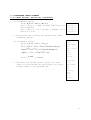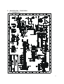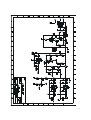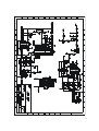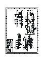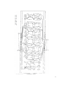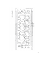
1
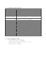
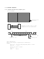
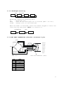
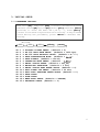
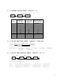
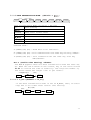
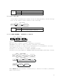
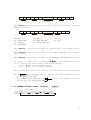
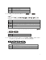
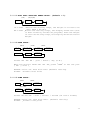
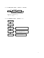
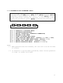
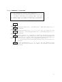
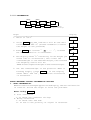
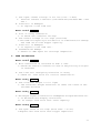
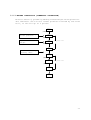
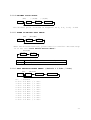
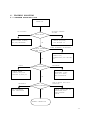
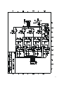
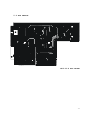
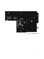
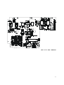
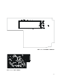
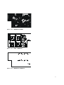
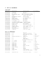
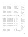
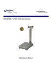
MAINTENANCE MANUAL
W22 INDICATOR SERIES
CONTENTS
1. INTRODUCTION
2. SPECIFICATIONS
2.1 SYSTEM BLOCK DIAGRAM
2.2 PHYSICAL LAYOUT OF ELECTRICAL CONNECTION
2.3 GENERAL SPECIFICATIONS
2.4 OPTIONAL INTERFACE
2.5 LOAD CELL CONNECTION
3. INITIAL SETUP
3.1 PARAMETER SETTING
3.2 CALIBRATION AND PARAMETER SETUP
3.3 PRINTTING LABEL FORMATS
4. TROUBLE SHOOTING
4.1 TROUBLE SHOOTING LOOP
4.2 PARTS AND COMPONENTS TROUBLE SHOOTING
5. ELECTRICAL CIRCUITRY
5.1 SCHEMATICS
5.2 PCB LAYOUT
6. BILL OF MATERIAL
7. APPENDIX
NOV 2005
Specifications and Function Subject to Change without Notice
1
1. INTRODUCTION
This maintenance manual contains of certain information that may result
in fraudulent use. Do not release any part of this manual to any end
users or un-authorized persons.
Built-in Pass Word configuration to prevent un-authorized settings
or alternations.
After servicing, it is necessary to go through all tests and procedures
to ensure the scale meets all the meteorological and approval
requirements.
Here are some features of the W22 series
1.
2.
3.
4.
5.
6.
7.
8.
Zero indicator
Tare indicator
Negative value indicator
Subtractive tare function
Power on zero function
Manual zero function
6 x 26mm wide angle LCD digits
Dual power: - By built-in rechargeable battery and external AC/DC
power adaptor
9. Low battery warning signal
10. Dual color charge status indicator
11. Full digital Calibration
12. AC/DC power adaptor included
13. Pass word configuration / parameter setting protection
14. User Programmable display resolution( up to 1/30000, Dual interval )
15. Built-in EL backlight
16. Equipped with RS232 interface
17. Optional printer(built-in or external) & relay output interface
2
2. SPECIFICATION
2.1 SYSTEM BLOCK DIAGRAM
LCD
LCD DRIVER
E+
LOAD ECELL S+
S-
A/D UNIT
INTERFACE
CPU
with ROM
POWER SUPPLY:
1. AC ADAPTOR
(9V/500mA)
2. RECHARGEABLE
BATTERY (6V 4Ah)
KEYBOARD
( 24 KEYS)
Description:
When an article is placed on the platter, the load of the article is
applied to the load cell inside the scale.
The resistance to the excitation current in the strain gauge will then
changed and the analog output signal varies.
It is amplified and digitized continuously by the A/D converter into
a digital signal. Subsequently, the resulting count is processed and
managed by the CPU. The CPU refers to the instructions from the keyboard,
and then conveys the output data to LCD driver, which formats the data
into readout on the display panels.
3
2.2 PHYSICAL LAYOUT OF ELECTRICAL CONNECTION
LOAD CELL
PLATFORM
INDICATOR
W12-70-X
8 PIN
CONNECOTR
DC JACK
RELAY BOARD
RECHARGEABLE
BATTERY
6V 4Ah
EXTERNAL PRINTER
D-SUB 25
(FEMALE)
CON7
PRINTER STATUS
W22-10-X
AC/DC IN
CON6
RELAY OUTPUT
LCD
CON5
PRINTER
CON1
MEMBRANE SW.
A/D
MODULE
SEN+
SENSIGSIG+
EXCEXC+
J1
CON4
CN2
BAT
+
RS232
MAIN BOARD
MINI PRINTER
CONTROL BOARD
D-SUB 9PIN
(FEMALE)
4
2.3 GENERAL SPECIFICATIONS
2.3.1 Overall View
2.3.2 Overall Dimension:
300(W) X 210(D) X 130(H)mm Max.
5
2.3.3 Technical Specifications
PERFORMANCE
Display
6 digit LCD , 26 m/m height
Display resolution
up to 30,000 divisions , minimum of 0.1μV / div.
Count-by
1 , 2 , 5 , 10 , 20 , 50
Display speed
25 times / second
Zero adjustment
-2mV to 20mV
Span adjustment
0.6 mV/V to 4mV/V full scale
Zero<0.3μV / ℃
Span<8ppm / ℃
Stability / Drift
Linearity<0.0033% R.O.
Noise<0.05μVp-p
Temperature 0℃〜40℃(32℉〜104℉)
Operating environment
Humidity <90 ﹪non condensing
A/D CONVERTER
Type
24 bit Sigma-Delta
Resolution
Up to 1,000,000 internal counts
Conversion rate
50 times/second
LOAD CELL
Excitation
5 volts for up to 8 ×350Ω load cell
+
-
+
-
+
Load cell connection 7 Wires(Exc , Exc , Sig , Sig , Sen +, Sen- , Gnd)
INTERFACE
RS-232C
Baud rate , transmission mode selectable
Printer
Centronics type(Built-in or External)
Relay Output
4 points of HI, OK, LO, Zero Band
POWER SUPPLY
AC Adaptor
9V / 500 mA
Rechargeable battery 6V , 4Ah
Power Consumption
Normal = 0.1W Charging = 5W
2.3.4 Main Components Used
Microprocessors: SM89516AC25P
Crystal Oscillator: 11.0592MHz
Display Device: WTN Liquid Crystal Display
A/D converter: AD7730
LCD driver IC: PCF8576CT
6
2.4 OPTIONAL INTERFACE
2.4.1 Serial RS-232C Port (D-SUB 9 pin)
PIN ASSIGNMENT
PIN NUMBER
1
2
3
4
5
6
7
8
ASSIGNMENT
DCD
TXD
RXD
DTR
GND
DSR
RTS
CTS
Short-circuited
internally
W22
PC
2
2
3
3
5
5
A SIMPLE WAY TO LINK IS PIN 2,3,5 USED
TO COMMUNICATE WITH THE OTHER DEVICE.
LSB
MSB
1
0
1
2
3
45
6
7
0
Data bits
Start bit (0)
Stop bit (1)
Parity bit
Type:EIA-RS-232C
Method:Half-duplex, asynchronous transmission
Format:
Baud rate :300,600,1200,2400,4800,9600 or 19200
Data bit :7 or 8
Parity bit:Even or None
Stop bit :1
Code
:ASCII
7
Transmission mode:
1. KPC(KEYBOARD PRINT CONTROL)
2. AUTO(AUTO PRINT PER WEIGHING EVENT,RESET
BY RETURN TO ZERO BAND,<100 div.)
3. SM(STREAM MODE,CONTINUOUS TRANSMISSION)
4. CMD(COMMAND MODE)
(REFER TO 3.1.1 Setting Basic Parameters)
Command Mode Transmission:
1. (READ)(CR)(LF)----ASCII CODE
PC à
R
E
A
D
CR
LF
52H
45H
41H
44H
0DH
0AH
Indicator à
,
HEADER 1
,
HEADER 2
……
,
CR LF
WEIGHT DATA(8 DIGITS)
UNIT
Data Format:
Format1
,
HEADER 1
,
HEADER 2
……
,
CR LF
WEIGHT DATA(8 DIGITS)
UNIT
Format2
,
HEADER 1
,
HEADER 2
HEADER 1
OL:Overload
ST:Stable
US:Unstable
……
CR
WEIGHT DATA(8 DIGITS)
HEADER 2
NT:Net weight
GS:Gross weight
LF
UNIT
Unit
kg,lb,g,t
8
Other Commands as
2.(ZERO)(CR)(LF)→
3.(TARE)(CR)(LF)→
4.(NTGS)(CR)(LF)→
follow:
To utilize ZERO function.
To utilize TARE function.
To change over Net/Gross.
2.4.2 Parallel Printer Interface (D-SUB 25 pin)
PIN ASSIGNMENT
PIN NUMBER
ASSIGNMENT
1
STROBE
2
D0
3
D1
4
D2
5
D3
6
D4
7
D5
8
D6
9
D7
11
BUSY
25
GND
2.4.3 Relay Output
1. RELAY OUTPUT CAPACITY (MAX):AC120V 1A,DC24V 2A。
2. 4 RELAY OUTPUT PIN SETS: HI、OK、LO、ZERO BAND.
PIN ASSIGNMENT
PIN NUMBER
1. HI (Normal Open)
2. HI (Common)
3. OK (Normal Open)
4. OK (Common)
5. LO (Normal Open)
6. LO (Common)
7. ZERO BAND (Normal Open)
8. ZERO BAND (Common)
ACTION
OPEN/
SHORT
OPEN/
SHORT
OPEN/
SHORT
OPEN/
SHORT
FIGURE
9
2.4.4 Backlight Facility
[MC] or [MR]
[Zero]
SF.8
XSEC
no.
LiGHt
Backlight Select by entering SF.8
no.
:Backlight off
XSEC
:Turn on the backlight for X seconds (Max = 20 sec)
LiGHt :Always turn on the backlight
When the XSEC is selected, press the number keypad to enter the
time setting and press “Zero” to confirm it.
Use keypad to enter
[Zero]
XX SEC
X SEC
SF.8
2.5 LOAD CELL CONNECTION (Circular connector 8 pin)
EXC+
SEN+
7
SIG+
SIG-
6
1
2
8
3
5
4
SENEXC-
LOAD CELL
PIN
1
2
3
4
5
6
7
8
jEX C+
kS EN +
lS ENmEX CnS IG+
oS IGpS .G .
qN C
LOAD CELL CONNECTOR (8PIN)
NAME
EXC+
SEN+
SENEXCSIG+
SIGS.G.
N.C.
10
3. INITIAL SETUP
3.1 PARAMETER SETTING:
NOTE. Hold〝MC〞 and press 〝ON〞 to enter to Parameter Setting
mode menu (Press〝MR〞(up) or〝MC〞(down)〝ESC〞(abandon)〝Zero〞
(confirm) to chose the menu:SF.1,SF.2,….), Press〝Zero〞
to enter to the each single feature for setting. If any mistake
occurs during the procedure, press 〝ESC〞to abandon the
setting.
[MC] or [MR]
SF.1
SF.1 ->
SF.2 ->
SF.3 ->
SF.4 ->
SF.5 ->
SF.6 ->
SF.7 ->
SF.8 ->
SF.9 ->
SF.10->
SF.11->
SF.12->
SF.13->
SF.14->
SF.15->
SF.2
SF.3
SF.4
...... SF.15
DIGITAL FILTER SETUP: (default = 5)
RS-232 BAUD RATE SETUP: (default = 9600 bps)
RS-232 DATA PROTOCOL SETUP: (default = E.7.1)
DATA TRANSMISSION MODE: (default =
)
DATA FORMAT: (default = Fort3)
OPERATION MODE SETUP: (default :
)
RELAY OUTPUT SETUP: (default = Out_Hi)
BACKLIGHT SELECTION: (default = 3 sec)
RELAY OUTPUT ZERO RANGE SETUP: (default = 0)
AUTO POWER OFF SETUP: (default = 30 min)
AUTO ZERO TRACKING RANGE SETUP: (default = 0)
DATE SETUP
TIME SETUP
BEEP MODE SETUP: (default = bEPoFF)
PASSWORD SETUP: (default = 0)
11
3.1.1 DIGITAL FILTER SETUP: (default = 5)
Press [MC] or [MR] to select the
parameter
[Zero]
SF.1
FiLt
X
FiLt XX
Digital
Filter
Strength
NO
WEAK
SF.1
0
1
2
3
4
5
6
7
8
9
10
STRONG
QUICK
Environment
Interference
Stability
BAD
SLOW
EXCELLENT
Response
Speed
3.1.2 RS-232 BAUD RATE SETUP: (default = 9600 bps)
[Zero]
[MC] or [MR]
br xxxx
SF.2
br xxxx
Baud Rate : (300bps , 600bps , 1200bps , 2400bps , 4800bps ,
9600bps , 19200bps)
3.1.3 RS-232 DATA PROTOCOL SETUP: (default = E.7.1)
[Zero]
SF.3
[MC] or [MR]
E.7.1
n.8.1
O.7.1
Parity Check Setting:
E.7.1 : Even parity check bit : 7 data bits, 1 stop bit.
N.8.1 : No parity check bit : 8 data bits, 1 stop bit.
O.7.1 : Odd parity check bit : 7 data bits, 1 stop bit.
12
3.1.4 DATA TRANSMISSION MODE: (default =
[Zero]
SF.4
)
[MC] or [MR]
no.
StrAn
StAbLE
k_Prn
n_HiLo
AVG_nd
ComAnd
Data Transmission Mode (Printer / RS-232)
no.
Send nothing
Continuous Send Mode
StAbLE
Send after stable Mode
k_Prn
Press “Print” to send Mode
Accumulation or HI,OK,LO send Mode
Health scale (Animal scale) Mode
ComAnd
RS232 Command Mode
Command Mode:
A.(READ)(CR)(LF)→
B.(ZERO)(CR)(LF)→
C.(TARE)(CR)(LF)→
D.(NTGS)(CR)(LF)→
Read data from Indicator.
This command works the same way with key “ZERO”.
This command works the same way with key “TARE”.
This command works the same way with key
“NET/GROSS”.
nUL X (Stable Time Setting) submenu:
The nUL X appears when the data transmission mode has been set
up. When the nUL X shows on the screen, key in the value from 1
to 20 to confirm the time of stability. The large the number is,
the scale needs the longer time to get stable.
Use keypad to key in
[Zero]
nUL XX
nUL X
SF.4
3.1.4.1 n_HiLo (default = nr_key )
If the data transmission mode is set as n_HiLo , then, an extra
step has to be taken after stable time setting.
[Zero]
n_HiLo
[MC] or [MR]
no.
nr_kEy
StAbLE
13
no.
Disable
Press “M+” to send data
Auto-Send data after stable
n_HiLo nr_key
StAbLE
AVG_nd
3.1.4.2
If the data transmission mode is set as AVG_nd than, an extra step
has to be taken after stable time setting.
[MC] or [MR]
[Zero]
AVG_nd
AVG_nd
no.
StAbLE
no.
Disable
StAbLE
Auto-Send After Stable
3.1.5 DATA FORMAT: (default = Fort3)
[Zero]
SF.5
[MC] or [MR]
Print
rS232
Data Format (RS-232 / PRINTER)
RS-232 has 3 data formats (Format1~Format3)
PRINTER can use 5 data formats (Format1~Format5)
Format1~Format3 is specially designed for peripheral Printer
(Dot-Matrix,9 pin or 24 pin) format
Format4 is for built in MINI PRINTER format
Format5is for peripheral THERMAL BAR CODE PRINTER (OS203DT) format
[Zero]
Print
[MC] or [MR]
Fort2
Fort1
[Zero]
Fort4 or 5
Fort5
[MC] or [MR]
Prno.
t_P.n.
When Fort = 1, Data format lists below (** there is a comma ”,”between
data and unit):
14
,
HEADER 1
,
HEADER 2
......
,
CR
LF
UNIT
Weighing Data (inc.+,- and
decimal, Totally 8 bits)
When Fort = 2, Data format lists below (** there is no comma ”,”between
data and unit):
,
HEADER 1
,
HEADER 2
HEADER 1
OL:OVERLOAD
ST:STABLE
US:UNSTABLE
......
Weighing Data (inc.+,-and
decimal, Totally 8 bits)
HEADER 2
NT:NET WEIGHT
GS:GROSS WEIGHT
CR
LF
UNIT
UNIT
kg,lb
When Fort=3, the format of data is:Date/Time + Fort2 data format
When Fort=4, the format of data is for MINI PRINTER (16 columns)
data format
When Fort=5, the format of data is for THERMAL PRINTER data format
), the Sub-Menu can set
In Fort4、5, (when SF.4 setting is
print copies for each weight and total weight:
Prno. à Set Each Weight Copies
t_P.n. à Set Total Weight Copies
Note: After the setting of copies, if press “ESC” then the display
shows
, By pressing “MC” or “MR” to set the language as below
E_Prn àEnglish Mode
( Only in Thermal Printer)
C_Prn àChinese Mode(BIG 5)
CC_Prn à Chinese Mode(GB)
3.1.6 OPERATION MODE SETUP: (default :
[MC] or [MR]
[Zero]
SF.6
)
no.
Hi_Lo
n_Add
n_HiLo
15
no.
Hi_Lo
n_Add
n_HiLo
Disable
Hi-Lo Check Mode
Accumulation Mode
Accumulation and Hi-Lo Check Mode
3.1.6.1 When the Operation Mode is in
:
and
[Zero]
or
Hi_out
Hi
no
HiLo
Lo
HiLo
ALL
Hi_Lo
no.
Disable
Output data
Output data
Output data
Output data
Lo range
Output data
Hi
HiLo
Lo
HiLo
ALL
when
when
when
when
the weight is higher than “Hi”value
the weight is between Hi and Lo
the weight is lower than “Lo”value
the weight is not between the Hi and
anyway
After the Operation Mode is confirmed, the display shows
stAblE
strAn
Continuous check HI-OK-LO status
StAbLE Check HI-OK-LO status after stable
3.1.6.2 When the Operation Mode is in
or
, Press “Zero”
to enter to sub-menu to set the RS-232 format:
[Zero]
n_Add
[MC] or [MR]
StAndA
OP5
ūEiGHt
StAndA RS-232 standard output format please see with Label
Print section。
RS-232 output format (please see the format 2 in
OP5
Section 3.1.5), it can connect to OP5 display board.
ūEiGHt Only weight data can be sent.
16
3.1.7 RELAY OUTPUT SETUP: (default = Out_Hi)
[Zero]
SF.7
[MC] or [MR]
Out Lo
no.
Out Hi
RELAY Output
Normality
Action
no
Disable
Disable
Out Lo Relay output status is Relay output status is
Close
Open
Out Hi Relay output status is Relay output status is
Open
Close
3.1.8 BACKLIGHT SELECTION: (default = 3 sec)
[Zero]
SF.8
[MC] or [MR]
XSEC
no.
LiGHt
Backlight Select
no.
:Backlight off
XSEC
:Turn on the backlight for X seconds (Max = 20 sec)
LiGHt :Always turn on the backlight
When the XSEC is selected, press the number keypad to enter the
time setting and press “Zero” to confirm it.
Use keypad to enter
[Zero]
SF.8
XX SEC
X SEC
3.1.9 RELAY OUTPUT ZERO RANGE SETUP: (default = 0)
[Zero]
SF.9
Use keypad to enter the value, Press Zero to confirm
ro XXd
SF.9
3.1.10 AUTO POWER OFF SETUP: (default = 30 min)
[Zero]
SF.10
Use keypad to enter the value, Press Zero to confirm
XX oFF
SF.10
Set auto off time, Maximum time is 99 minutes.
17
3.1.11 AUTO ZERO TRACKING RANGE SETUP: (default = 0)
[MC] or [MR]
[Zero]
SF.11
r0.0 XXd
d0.0 XXd
:Within the setting range, the weight is forced to be
zero (Max = 99 div)
d0.0 XXd :Within the setting range, the display shows zero (but
it does counting inside the program); when the weight
is over the setting range, the display shows the actual
weight.
r0.0 XXd
3.1.12 DATE SETUP:
[TARE]
[ZERO]
SF.12
XX’ XX’ XX
[ZERO]
y XXXX
EnAbLE
[MC] or [MR]
EnAbLE
diSAbL
EnAbLE
Format XX’ XX’ XX : year / month / day (C.E.)
When the monitor shows XX’ XX’ XX, press〝TARE〞to set the year
( EX. y 2003 )。
EnAbLE:Print out Date with Data (default setting)
diSAbL :Disable Date Print
3.1.13 TIME SETUP:
[ZERO]
SF.13
[ZERO]
XX:XX:XX
EnAbLE
[MC] or [MR]
EnAbLE
diSAbL
EnAbLE
Format XX:XX:XX : hour / minute / second (24 hours format)
EnAbLE:Print out time with data. (default setting)
diSAbL :Disable time print
18
3.1.14 BEEP MODE SETUP: (default = bEPoFF)
[Zero]
SF.14
[MC] or [MR]
bEP on
bEPoFF
BEEP Mode Setting
bEPoFF :Disable Beep
bEP on :Beep
3.1.15 PASSWORD SETUP: (default = 0)
SF 15
0
XXXXXX
Input old Password,
default = 0
YYYYYY
Input New Password,
Max= 6 digits
YYYYYY
Confirm Password
19
3.2 CALIBRATION AND PARAMETER SETUP:
NOTE: Press〝Tare〞and hold,then Press〝ON〞to enter the Calibration
Setting mode(Press〝MR〞(up) or〝MC〞(down)〝ESC〞(abandon)〝Zero〞
(confirm) to chose the menu:CF.1, CF.2,….), Press〝Zero〞to enter
to the each single feature for setting. If any mistake occurs
during the procedure, press 〝ESC〞to abandon the setting.
[MC] or [MR]
CF.1
CF.1
CF.2
CF.3
CF.4
CF.5
CF.6
CF.7
CF.8
CF.9
->
->
->
->
->
->
->
->
->
CF.2
CF.3
CF.4 ……
CF.9
CAPACITY & DIVISION SETUP
CALIBRATION PROCEDURES
WEIGHT CORRECTION (LINEARITY CORRECTION)
DECIMAL POINT SETUP
POWER ON WEIGHT UNIT SETUP
ZERO TRACKING RANGE SETUP: (default = 1.5div / 1sec)
POWER ON AUTO ZERO RANGE SETUP: (default = 0%)
MANUAL ZERO RANGE SETUP: (default = 100%)
MOTION DETECTION SETUP: (default = 1.0-0.5)
NOTE:
* 1. When password function disable, CF.1~CF.9 will not be allowed
to access.
* 2. If indicator is protected by password, enter correct password
in order to access this menu.
20
3.2.1 CAPACITY & DIVISION
1. Use KeyPad to enter the Capacity.
2. The decimal point and weight unit can be set
in CAP.1 and CAP.2 by using “MR” and “MC”.
3. Press “Zero” to confirm and enter to next step.
4. Press “MR” and “MC” to set the division
CF.1
[ZERO]
CAP. 1
Maximum Capacity。( Graduation / Maximum Capacity >=
1/30000)
[ZERO]
Ct. x
Second Graduation. ( 1, 2, 5, 10, 20, 50, Notice: the
accuracy = Minimum Graduation / Maximum Capacity =<
1/30000)
[ZERO]
CAP. 2
[ZERO]
Ct. y
First Capacity. (extract a capacity between zero and
max capacity. The indicator will use first graduation
from zero to first capacity and use second graduation
from first capacity to maximum capacity).
** If customers only need one graduation, press “zero”to
escape.
First Graduation. ( 1, 2, 5, 10, 20, 50, Notice: the
total divisions = Max1 / e1 + Max2 / e2 should not exceed
30,000)
21
3.2.2 CALIBRATION
[ZERO]
CF. 2
[ZERO]
. . . . .
CAL.-0
OK
WAit
0
XXXX
1.Counterweight
2.Input the weight
Steps
1. Enter to〝CF.2〞
2. Press ZERO key,The indicator will do the Zero
Calibration 〝CAL.-0〞(Please remember to remove
the weight on the platform)
3. Press ZERO If it shows〝 . . . . .. .〞, it means
the Zero Calibrtion is successful.
4. The display shows〝0〞Please key in the weight you
would like to calibration.; The closer the
counterweight to the maximum weight, the accurate
the weighing result will be.
XXXX:Please input the weight of the counterweight.
5. Put the counterweight on the platform. When it
becomes stable, Press ZERO , If the display
shows〝WAit〞and〝OK〞, it means the calibration
is successful.
Display
CF.2
CAL-0
. . . .
0
XXXX
WAit
OK
ERROR MESSAGES DURING CALIBRATION PROCESS
1. ZERO CALIBRATION:
When below error messages appear on the display, the zero calibration
is invalid. Follow the steps to solve the problems.
Error Code: AAAAAA
a. Poor connection
I. To check the connector wirings
b. Wrong connection
I. To check SIG+ and SIGII. To see if the polarity of signal is reversed.
22
c. The input offset voltage is too low (over -1.5mV)
I. Parallel connect a resistor (100-500K ohm) between EXC + and
SIG +
d. Load Cell is damaged
I. To replace a new load cell
Error Code: UUUUUU
a. Poor or wrong connection
I. To Check the connector wirings
b. The offset voltage is too high (over+2mV)
I. The load cell capacity is too small or it is malfunction. Change
new load cells with bigger capacity.
c. Load cell is damaged
I. To replace a new load cell.
d. Thunderstorm damage
I. Return to UWE agent for thorough inspection.
2. SPAN CALIBRATION
Error Code: LLLLLL
a. Wire Connection is reversed at SIG+ & SIGI. Check the load cell connector to see if the polarity of signal
is reversed.
b. The load cell receipting direction is wrong
I. Check all load cells for correct installation.
Error Code: CCCCCC
a. The calibrate weight is too light
I. The calibrate weight should be at least 100 times of the
minimum division
Error Code: -----a. The output signal of load cell is inadequate for Span Calibration.
I. To decrease the display resolution.
II. To change load cells with lower capacity.
Error Code: UUUUUU
a. The span value is too high (more than + 15 mV)
I.Replace new load cells with bigger capacities
23
3.2.3 WEIGHT CORRECTION (LINEARITY CORRECTION)
Enter to the CF.3, gradually adding counterweight on the platform.
The indicator can fix the linear problem occurred by the Load
Cell, It can fix up to 5 points.
CF.3
[ZERO]
Put the counterweight
on the platform.
XXXX
[ZERO]
Input the correct
weight.
YYYY
1st point fix
[ZERO]
OK
You can abandon by
pressing “ESC”
XXXX
[ZERO]
YYYY
2nd point fix
[ZERO]
OK
OK
24
3.2.4 DECIMAL POINT SETUP:
[Zero]
CF.4
[•] or [Tare]
[•] or [Tare]
dP 0.0
dP 0
dP 0.000
The decimal point is moved in sequence as 0, 0.0, 0.00, 0.000
3.2.5 POWER ON WEIGHT UNIT SETUP:
[Zero]
CF.5
[MC] or [MR]
Lb
kg
When the unit has been set, press “Zero” to confirm. The next step
is to set the “Unit Switch Button Menu”:
[MC] or [MR]
Ut_CHG
Ut_oLy
Ut_CHG Press〝Unit〞to switch the weight unit
Ut_oLy Can only use one unit.
3.2.6 ZERO TRACKING RANGE SETUP: (default = 1.5div / 1sec)
[Zero]
CF.6
[MR] or [MC]
0t. 0.5-1
0t. no.
no. :Disable
0.5-1 :0.5 div.
1.0-1 :1.0 div.
1.5-1 :1.5 div.
2.0-1 :2.0 div.
2.5-1 :2.5 div.
0.5-2 :0.5 div.
1.0-2 :1.0 div.
1.5-2 :1.5 div.
2.0-2 :2.0 div.
2.5-2 :2.5 div.
/
/
/
/
/
/
/
/
/
/
1
1
1
1
1
2
2
2
2
2
0t. 2.5-2
sec.
sec.
sec.
sec.
sec.
sec.
sec.
sec.
sec.
sec.
25
3.2.7 POWER ON AUTO ZERO RANGE SETUP: (default = 0%)
[MC] or [MR]
[Zero]
CF.7
0
2
10
20
100
2 %
0 %
100 %
%
%
%
%
%
3.2.8 MANUAL ZERO RANGE SETUP: (default = 100%)
[MC] or [MR]
[Zero]
CF.8
2
10
20
100
10 %
2 %
100 %
%
%
%
%
3.2.9 MOTION DETECTION SETUP: (default = 1.0-0.5)
[Zero]
CF.9
0.5-0.5
1.0-0.5
2.0-0.5
3.0-0.5
4.0-0.5
0.5-1.0
1.0-1.0
2.0-1.0
3.0-1.0
4.0-1.0
[MC] or [MR]
M 1.0-0.5
M 0.5-0.5
:0.5
:1.0
:2.0
:3.0
:4.0
:0.5
:1.0
:2.0
:3.0
:4.0
div
div
div
div
div
div
div
div
div
div
/
/
/
/
/
/
/
/
/
/
0.5
0.5
0.5
0.5
0.5
1.0
1.0
1.0
1.0
1.0
M 4.0-1.0
sec.
sec.
sec.
sec.
sec.
sec.
sec.
sec.
sec.
sec.
26
3.3 PRINTTING LABEL FORMATS
3.3.1 Mini Printer (Built-in) (Internal)
(1) Parameter setup:
SF.4 → n_HiLo → nUL1 → nr_kEy
SF.5 → Fort 4 → XXX → Press〝ESC〞key till
“SF.5”appears
SF.6 → Hi_Lo → no → StrAm or StAbLE (P.15
Section 3.1.6)
600.2kg
L
1200.5kg G
1799.6kg G
1799.6kg G
2400.8kg H
** Only print the receipt for weight and check
weighing status.
(2) Parameter setup:
SF.4 → n_HiLo → nUL1 → nr_kEy
SF.5 → Fort 4 → Prno → Prno.1 ( Set each time print
[MC]
[MC]
Copies) → Prno. → t_P.n.1 (Set total weight prin
20003/09/17
17:45
P/No. ABC123
Ser.
N.W.
1
600.1kg
Tare
copies) → t _ P.n. → Press "ESC" key
0.0kg
G..W.
SF.6 → n_Add → StAndA
600.1kg
20003/09/17
** Customer can choose print copies for each
label to be printed out and copies for total
weight label to be printed out.
17:54
P/No. ABC123
Ser.
2
N.W.
1200.1kg
Tare
0.0kg
G..W.
1200.1kg
27
(3) Parameter setup:
SF.4 → n_HiLo → nuL1 → nr_kEy
SF.5 → Fort 3
SF.6 → n_HiLo → no → StrAm or StAbLE
(P.15 Section 3.1.6)
** Print weight receipt
(Time+Series+Weight+Checking Status+Total)
(4) Parameter setup:
SF.4 → n_HiLo → nuL1 → nr_kEy
SF.5 → Fort 3
SF.6 → n_Add → StAndA
** Print weight receipt (Time+Series+Weight
+Total)
2003/04/23 16:05
P/No. AB-123
--------------------------Max:
32.0kg
Min:
12.0kg
--------------------------01
10.0kg L
02
20.0kg G
03
30.0kg G
04
35.0kg H
05
20.0kg G
--------------------------06
10.0kg L
---------------------------
20003/09/17
17:45
P/No. ABC123
----------------------------------------------01
599.9kg
02
1200.3kg
03
2400.6kg
04
3000.2kg
05
2400.5kg
----------------------------------------------Total 9601.5kg
28
(5) Parameter setup:
SF.4 → n_HiLo → nUL1 → nr_kEy
SF.5 → Fort 2
SF.6 → n_Add → StAndA
20003/09/17
17:45
P/No. ABC123
-----------------------------------------------
** Print weight receipt (Time+Series+Weight
+Total)
** Print each weight and current accumulation
weight data
06
599.9kg
599.9kg
07
1200.3kg
1801.2kg
08
2400.6kg
4201.8kg
09
3000.2kg
7202.0kg
(6) Parameter setup:
SF.4 → AVG_nd → nUL3 → StAbLE
SF.5 → Fort 4 → XXX→ Press"ESC〞
until SF.5 appears
n_Add
SF.6 →
→ StAndA
2003/10/17 16:40
600.3kg
2003/10/17 16:40
1200.6kg
** Print weight receipt in health scale mode
29
3.3.2 Thermo Printer (External Printer):
(1) Parameter setup:
SF.4 → n_HiLo → nuL1 → nr_kEy
SF.5 → Fort 5 → Prno → Prno.1 ( Set each time print
[MC]
[MC]
Copies) → Prno. → t_P.n.1 (Set total weight prin
copies) → t _ P.n. → Press "ESC" → E _Prn
SF.6 → n_HiLo → no → StrAm or StAbLE
(P.15 Section 3.1.6)
20003/09/17 17:45
P/No. ABC123
SER.
N.W.
Tare
G..W.
1
600.1kg
0.0kg
600.1kg
20003/09/17 17:55
P/No. ABC123
** Customer can choose print copies for each
label to be printed out and copies for
total weight label to be printed out.
SER.
N.W.
2
1200.1kg
Tare
0.0kg
G..W.
1200.1kg
** English Label Format
20003/09/17 17:55
P/No. ABC123
Total
2
T N.W. 1800.2kg
Tare
0.0kg
T G..W. 1800.2kg
30
(2) Parameter setup:
SF.4 → n_HiLo → nuL1 → nr_kEy
SF.5 → Fort 5 → Prno → Prno.1 ( Set each time print
[MC]
[MC]
Copies) → Prno. → t_P.n.1 (Set total weight prin
copies) → t _ P.n. → Press "ESC" → C_Prn
SF.6 → n_HiLo → no → StrAm or StAbLE
(P.15 Section 3.1.6)
20003/09/17 17:45
批號 ABC123
序號
淨重
1
600.1 公斤
空重
0.0 公斤
總重
600.1 公斤
20003/09/17 17:45
批號 ABC123
** Customer can choose print copies for each
label to be printed out and copies for
total weight label to be printed out.
序號
淨重
2
1200.1 公斤
空重
0.0 公斤
總重
1200.1 公斤
** Traditional Chinese Label Format
20003/09/17 17:46
批號 ABC123
總計
2
總淨重
1800.2 公斤
總空重
總重量
0.0 公斤
1800.2 公斤
31
(3) Parameter setup:
SF.4 → n_HiLo → nuL1 → nr_kEy
SF.5 → Fort 5 → Prno → Prno.1 ( Set each time print
[MC]
[MC]
Copies) → Prno. → t_P.n.1 (Set total weight prin
copies) → t _ P.n. → Press "ESC" → C C _Prn
SF.6 → n_HiLo → no → StrAm or StAbLE
(P.15 Section 3.1.6)
20003/09/17 17:45
货号 ABC123
序号
净重
1
600.1 公斤
皮重
0.0 公斤
毛重
600.1 公斤
20003/09/17 17:45
货号 ABC123
** Customer can choose print copies for each
label to be printed out and copies for
total weight label to be printed out.
序号
净重
2
1200.1 公斤
皮重
0.0 公斤
毛重
1200.1 公斤
** Simplified Chinese Label Format
20003/09/17 17:46
货号 ABC123
(4) Parameter setup:
SF.4 → StAbLE
SF.5 → Fort 5 → Prno → Prno.1 ( Set each time print
[MC]
累计
2
总净重
1800.2 公斤
总皮重
0.0 公斤
总毛重
1800.2 公斤
600.4 kg
[MC]
Copies) → Prno. → t_P.n.1 (Set total weight prin
copies) → t _ P.n. → Press "ESC" → E_Prn
SF.6 → no. → StArdA
** Only print the weighing data with enlarged font
32
(5) Parameter setup:
SF.4 → n_HiLo → nuL1 → nr_kEy
SF.5 → Fort 5 → Prno → Prno.1 ( Set each time print
[MC]
Ser.
1
600.4 kg
[MC]
Copies) → Prno. → t_P.n.1 (Set total weight prin
copies) → t _ P.n. → Press "ESC" → E_Prn
SF.6 → n_Add → StAndA
** Print the weight data with Enlarged font
version and printed out the count for each
individual label and total label number.
Ser.
2
600.4 kg
Total
2
1200.8 kg
(6) Parameter setup:
SF.4 → n_HiLo →nuL1 →nr _kEy
SF.5 → Fort 5 → Prno → Prno.1 ( Set each time print
[MC]
[MC]
600.4 kg
Copies) → Prno. → t_P.n.1 (Set total weight prin
copies) → t _ P.n. → Press "ESC" → E_Prn
SF.6 → Hi_Lo → strAm
** Print the weight data in checking mode with enlarged font
version
English alphabet contrast list (right picture)
" "
33
4. TROUBLE SHOOTING
4.1 TROUBLE SHOOTING LOOP
POWER ON
DISPLAY RANDOM
FIGURE
NO DISPLAY
SELF-TEST?
CHECK POWER SUPPLY,
CPU,LCD,KEYBOARD
OK
CHECK SEGMENTS
THEN ZERO?
OK
GHOST
CHECK CPU,LCD,
LCD DRIVER IC
SOME SEGMENTS DISAPPEAR
CHECK LCD,
CONNECTORS,LCD DRIVER
IC
UNSTABLE
PROPER READOUT?
CHECK POWER
SUPPLY,LCD,LCD
DRIVER IC,R24,25
OK
CHECK STRUCTURE OF
PLATFORM ,LOAD
CELL,A/D UNIT,
BAD SOLDERING
CAN’T REACH THE FULL
CAPACITY
INCORRECT
CORRECT READOUT?
RE-CALIBRATE
THE INDICATOR
OK
CHECK STRUCTURE OF
PLATFORM,LOAD
CELL,OFFSET
VALUE
NORMAL OPERATION
34
4.2 PARTS AND COMPONENTS TROUBLE SHOOTING
4.2.1 Power Supply Checking
4.2.1.1 Relevant parts:
Main Board (W22-10-X)
Q4 (C1061)
ZD1 (8.2V)
D13~D16 (1N4002)
Q7 (A1515)
Q5 (C945)
R28 (1.2 ohm, 1/2W)
U10 (2940-5V)
U11 (2940-5V)
U12 (2940-5V)
Q9 (A733)
DC JACK(SCD-021)
Description:
1) AC Adaptor: This AC Adaptor provides power of DC9~12V,500mA
2) Battery: Built-in Rechargeable Battery 6V/4Ah
3) How Battery is charged completely?
The charging voltage is regulated by Q4 (C1061) and ZD1 (8.2V) for
about 7 volts.
The charging current will go down automatically when voltage reached.
Q5 (C945) and R28 (1.2R, 1/2W) provide Over-Current protection.
35
4) +5VA power drives analog system including A/D converter device
(IC 7730).
U11 (2940-5V) is a 5volts Voltage Regulator.
5) +5V power drives digital circuit systems.
U10 (2940-5V) is a 5volts Voltage Regulator.
6) Auto-off:
If the indicator is under LO-BAT situation, after fixed minutes,
CPU will launch a high_to_low pulse to pull down the base pole
of Q8(C945), then Q7 cuts off, the indicator will be shut down
immediately.
7) Low Power Detection:
The Q9 (A733) is designed to detect the power level. When battery
voltage is less than 5.5V, it will release a high potential signal
to CPU, and then CPU will instruct LCD display to show LO-BAT symbol.
4.2.1.2 Input voltage: 5.5V or higher
Check and recharge battery if voltage less than 5.5V.
Check DC-JACK or AC Adaptor if been defective.
4.2.1.3 System voltage (Vcc): 5V +/- 10%
Check that the system voltage is within 5V +/- 10%
a) less than 4.5V, the CPU may not work properly.
b) more than 6V, ghost will appear on LCD.
4.2.2 Platform Structure Checking
The platter device shall not touch anything around itself during
operation. Check that the platter is not contacted with the upper
(no load) and/or lower (with load) stopper if equipped.
4.2.3 LCD Display Checking
4.2.3.1 Check that it is soldered and connected properly between LCD
and driver IC (PCF8576), driver IC (PCF8576) and CPU.
4.2.3.2 Check whether LCD is broken.
4.2.4 CPU Checking
4.2.4.1 Check that all pins are seated properly into the socket.
4.2.4.2 Check that the Crystal Oscillator works.
4.2.4.3 Check the RESET is normally low.
36
4.2.5 A/D Unit Checking
4.2.5.1 Check that the +5VA power is correctly fed to the
A/D unit.
4.2.5.2 Check that the signal output of load cell is adequate.
4.2.5.3 Check OP. amplifiers & A/D converter (AD7730).
When no error is found with the above checking procedures, the trouble
can be caused by the load cell or the PCB itself. Replace a new one
could be better to identify the defectiveness.
In this way, the readout of weight would be varied because of the output
voltage of load cell gaining different span value, so re-calibration
is necessary after this replacement.
37
5. ELECTRICAL CIRCUITRY
5.1 SCHEMATICS
38
39
40
41
42
5.2 PCB LAYOUT
W22-10-4 TOP LAYER
43
W22-10-4 BOTTOM LAYER
44
W22-10-4 TOP OVERLAY
45
W22-10-4 BOTTOM OVERLAY
W12-70-1 TOP LAYER
46
W12-70-1 BOTTOM LAYER
W12-70-1 TOP OVERLAY
W12-70-1 BOTTOM OVERLAY
47
6. BILL OF MATERIAL
STRUCTURE
Parts No.
A0905600800
A0905600801
A0906000210
A1202060251
A1208020351
A1207060250
A1600060400
A60********
B0W22000000
C1W22030001
C1W22031000
E9W22000030
F0007NBS102
G0001T01000
G0001T01100
G0001T00101
G0004DW0001
A1007000004
A1007000011
A1204010150
A1204020800
A0750122050
A0904120090
Description
Specification
Qty Remark
CONNECTOR
PLT-168-R
1
CONNECTOR
PLT-168-P
1
D.C. JACK
SCD-021
1
WIRE ARRAY
6PIN 25cm(SINGLE HOUSING) 1
BATTERY WIRE ARRAY
2PIN 35cm(SINGLE HOUSING) 1
CABLE
2464#24,6PIN 25cm
1
RECHARGEABLE BATTERY
GP4-6/6V 4Ah
1
ADAPTOR
***V/9V 500mA
1
MEMBRANE SW.
W22 SERIES(24 KEY)
1
PANEL OVERLAY
W22 SERIES
1
KEYBOARD OVERLAY
W22 SERIES
1
P.C.B. KIT
W22-10-X
1
S/S BATTERY CLAMP
NBS SERIES
1
INDICATOR HOUSING(UNDER) T SERIES,COATING
1
INDICATOR HOUSING(UPPER) T SERIES,COATING
1
PLASTIC COVER
MINI PRINTER
1
RUBBER PAD
DW SERIES,∮16*3.5t
4
FERRITE CORE
T-28.3*13.8*13.5mm
1
FERRITE CORE
19*6.5*32mm,CLAMP TYPE 1
CONDUCTIVE WIRE
15cm, BLACK
1
WIRE ARRAY
2PIN 80cm(0.18/30)
1
CAPACITOR(CCFT)
1200pF/50V
4
CONNECTOR
D-SUB 09F SOLDER
1
W22-10-X MAINBOARD
E0W22000011
A0202093462
A0206022770
A0203077300
A0204745732
A0207029400
A0250013020
A0208085760
A0201089516
A0250080540
A0300000016
A0300000040
A0102000292
A0401007150
A0401007330
A0401009450
A0401010610
A0401015150
A0403008170
A0501004002
A0501004148
A0503020082
A0625050000
P.C.B.
W22-10-X
I.C.
93C46PC27 OR 93LC46
I.C.
OPA2277UA[BURR-BROWN]
I.C.
AD7730BN
I.C.
74HC573
VOLTAGE REGULATOR I.C.
LM2940CT-5
I.C.
DS1302
I.C.
PCF8576CT
I.C.
SM89516AC25P
I.C.
S80745AL OR S80845CLY-B
I.C. SOCKET
16 PIN
I.C. SOCKET
40 PIN
L.C.D
054821-1, 6 DIGITS
TRANSISTOR
A715
TRANSISTOR
2SA733
TRANSISTOR
2SC945
TRANSISTOR
H1061C OR D880
TRANSISTOR
A1515
PHOTO COUPLER
K817P
DIODE
1N4002
DIODE
1N4148
ZENER DIODE
1/2W 8V2(9A3)
L.E.D.
ROUND,5mm,(RED,GREEN)
1
1
1
1
4
3
1
1
1
1
1
1
1
1
3
4
1
2
3
4
6
2
1
U3
U23
U21
U5,7,9,13
U10-12
U4
U8
U2
U1
U6
U2
LCD1
Q11
Q1,6,9
Q3,5,8,12
Q4
Q2,Q7
U18-20
D13-16
D1-4,D6,12
ZD1,2
LED1
A0701106017
CAPACITOR (EC)
9
EC1-9
10uF/25V(SS TYPE)
48
A0701107016
A0701227017
A0701228016
A0701476016
A0701478016
A0702106016
A0713103251
A0713105064
A0713224101
A0730104050
CAPACITOR
CAPACITOR
CAPACITOR
CAPACITOR
CAPACITOR
CAPACITOR
CAPACITOR
CAPACITOR
CAPACITOR
CAPACITOR
(EC)
(EC)
(EC)
(EC)
(EC)
(TC)
(MEF)
(MEF)
(MEF)
(MLC)
A0731104050
CAPACITOR (X7R)
A0740030050
A0740047050
A0740101050
CAPACITOR (CC)
CAPACITOR (CC)
CAPACITOR (CC)
A0802010205
A0802010309
A0803041002
A0803043001
A0804041503
A0804044701
A0804044702
A0804045003
A0805020120
A0805021101
A0805041101
RESISTOR NETWORK
RESISTOR NETWORK
METAL FILM RESISTOR
METAL FILM RESISTOR
METAL FILM RESISTOR
METAL FILM RESISTOR
METAL FILM RESISTOR
METAL FILM RESISTOR
CARBON FILE RESISTOR
CARBON FILE RESISTOR
CARBON FILE RESISTOR
A0805041102
CARBON FILE RESISTOR
A0805041103
CARBON FILE RESISTOR
A0805041180
A0805041203
A0805041221
A0805041223
A0805041272
A0805041471
A0805041472
CARBON
CARBON
CARBON
CARBON
CARBON
CARBON
CARBON
A0805041473
CARBON FILE RESISTOR
A0901010040
A0901010060
A0901010120
A0902010020
A0907010030
A0910000140
A0910100130
CONNECTOR
CONNECTOR
CONNECTOR
CONNECTOR
PIN PLUG
CONNECTOR(FPC)
SOCKET STRIP
FILE
FILE
FILE
FILE
FILE
FILE
FILE
RESISTOR
RESISTOR
RESISTOR
RESISTOR
RESISTOR
RESISTOR
RESISTOR
100uF/16V
220uF/16V(SS TYPE)
2200uF/16V
47uF/16V
4700uF/16V
10uF/16V(106)
0.01uF/250V
1uF/63V(105)(7.5mm)
0.22uF/100V(224)
104Z
4
2
1
1
2
3
4
1
1
27
EC11-14
EC17-18
EC10
EC19
EC15-16
TC1-3
C36-38,40
C39
C47
C3-9,19,22
23-33,41-42
46,49-51,57
0.1uF/50V(104)
4 C34-35,45,
48
30pF/50V(30)
2 C1-2
47pF/50V(47)
2 C43,44
100pF/50V(101)
24 C10-18,20,
21,67-76,
58-60
1KΩ
5 PIN
1 NR3
10KΩ
9 PIN
2 NR1-2
10KΩ
1/4W(10PPM)
2 R52,53
3KΩ
1/4W(10PPM)
1 R54
150KΩ 1/4W(25PPM)
1 R37
4.7KΩ 1/4W(25PPM)
2 R5,26
47KΩ
1/4W(25PPM)
2 R55,56
500KΩ 1/4W(25PPM)
1 R39
1.2Ω
1/2W
1 R28
100Ω
1/2W
1 R27
100Ω
1/4W
13 R8-15,22-23
,57-59
1KΩ
1/4W
6 R4,21,30,34
,41-42
10KΩ
1/4W
7 R1,25,36,49
,50,60-61
18Ω
1/4W
1 R20
20KΩ
1/4W
1 R24
220Ω
1/4W
2 R29,62
22KΩ
1/4W
1 R38
2.7KΩ 1/4W
1 R40
470Ω
1/4W
1 R46
4.7KΩ 1/4W
5 R18,33,63,
64-65
47KΩ
1/4W
13 R2-3,6-7,
16-17,19,
31-32,35,
43-45
4 PIN WAFER
1 CON3
6 PIN WAFER
2 CON4,7
12 PIN WAFER
1 CON5
2 PIN WAFER,PITCH=3.9mm 1 CN2
1 x 3 PIN 180°
1 J3
14 PIN 180°
1 CON1
SIP, 1 x 13(FEMALE)
1 LCD1
49
A0910100140
A1002225000
A1008000001
A1008000011
A1100032768
A1100249153
A1100311060
A1400000006
A1401005000
A1500000004
A5004000002
A5008000002
A1602030000
A0203002322
F0015000014
F0015000015
A0602050001
A0604050001
A0605050000
SOCKET STRIP
INDUCTOR
EMI FILTER
LINE FILTER
CRYSTAL
CRYSTAL
CRYSTAL
BACK LIGHT
BACK LIGHT INVERTER
BUZZER
HEAT SINK
BATTERY HOLDER
BUTTON BATTERY(3V)
I.C.
A/D PROTECTION BOX
A/D PROTECTION BOX
L.E.D.(SUPER BRIGHT)
L.E.D.(SUPER BRIGHT)
L.E.D.(SUPER BRIGHT)
SIP, 1 x 14(FEMALE)
2.2uH
DSS306-55Y5S471M100
SB4515-600
32.768KHZ
4.9152MHZ/us
11.0952MHZ/us
130.0*44mm
5V/90cm2
OBO-15210
MB-204-20
2032
CR2032
MAX232CPE
79*68*12(UPPER)
79*68*3 (UNDER)
RED,ROUND,∮5
YELLOW,ROUND,∮5
GREEN,ROUND,∮5
1
1
2
5
1
1
1
1
1
1
4
1
1
1
1
1
3
1
1
LCD1
L1
EMI1-2
L3-7
X2
X4
X1
EL1
IN1
BZ1
Q4,U10-12
BAT1
BAT1
U6
LED2,5,6
LED4
LED3
OPTIONAL MINI PRINTER
A9001000017
A1202060151
A1202120101
MINI PRINTER SET
WIRE ARRAY
WIRE ARRAY
UP-A16P
1
6PIN 15cm(DUAL HOUSING)
1
12PIN 10cm(SINGLE HOUSING) 1
CON7
CON5
OPTIONAL EXTERNAL PRINTER INTERFACE
A1250251240
WIRE ARRAY+DSUB25
12PIN 40cm(SINGLE HOUSING) 1
CON5
W12-70-X RELAY OUTPUT
E1W12100000
P.C.B. KIT
W12-70-X
1
A1202060300
WIRE ARRAY
6PIN 30cm(DUAL HOUSING)
1
A1202090380
WIRE ARRAY
9PIN 38cm(DUAL HOUSING)
1
A5005000084
TERMINAL BLOCK
DT-25-A02W-04
2
==============================================================================
50
7. APPENDIX
PARTS EXPLOSION:
1
2
3
5
6
7
4
8
11
12
9
10
13
14
17
15
51
ITEM
QTY
PART NO.
PART NAME
DESCRIPTION
1
1
C1W22030001 PANEL OVERLAY
2
1
G0001T01100 INDICATOR HOUSING(UPPER) T SERIES,COATING
3
1
A9001000017 MINI PRINTER SET
UP-A16P
4
1
E9W22000030 P.C.B. KIT
W22-10-X
5
1
C1W22031000 KEYBOARD OVERLAY
W22 SERIES
6
1
B0W22000000 MEMBRANE SW.
W22 SERIES(24 KEY)
7
1
G0001T00101 PLASTIC COVER
MINI PRINTER
8
1
A0906000210 D.C. JACK
SCD-021
9
1
A1007000004 FERRITE CORE
T28.3*13.8*13.5mm
10
1
A0905600800 CONNECTOR
PLT-168-R
11
1
G0001T01000 INDICATOR HOUSING(UNDER) T SERIES,COATING
12
1
A1250251240 WIRE ARRAY+DSUB25
12PIN 40cm(SINGLE HOUSING)
13
1
A0904120090 CONNECTOR
D-SUB 09F SOLDER
14
1
F0007NBS102 S/S BATTERY CLAMP
NBS SERIES
15
1
A1600060400 RECHARGEABLE BATTERY
GP4-6/6V 4Ah
16
1
E1W12100000 P.C.B. KIT
W12-70-X
17
4
G0004DW0001 RUBBER PAD
DW SERIES,∮16*3.5t
W22 SERIES
52
53
54
55
56
57
58
59
60
61
62
63