1
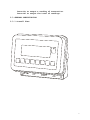
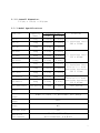
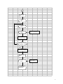
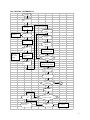
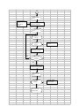
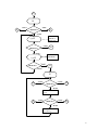
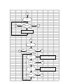
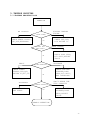
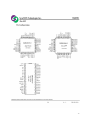
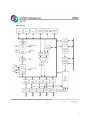
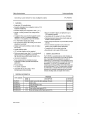
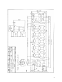
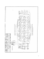
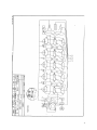
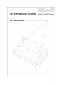
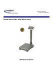
MAINTENANCE MANUAL PS2 SERIES CONTENTS 1. INTRODUCTION 2. SPECIFICATIONS 2.1 SYSTEM BLOCK DIAGRAM 2.2 PHYSICAL LAYOUT OF ELECTRICAL CONNECTION 2.3 GENERAL SPECIFICATIONS 2.4 INTERNAL SETTINGS AND CALIBRATION METHODS 2.5 FLOW CHART 3. TROUBLE SHOOTING 3.1 TROUBLE SHOOTING LOOP 3.2 PARTS AND COMPONENTS TROUBLE SHOOTING 4. ELECTRICAL CIRCUITRY 4.1 SCHEMATICS 4.2 PCB LAYOUT 5. BILL OF MATERIAL 6. APPENDIX JUNE 2003 REV 4 Specifications and Function Subject to Change without Notice 1 1. INTRODUCTION The PS2 series are designed and programmed according to the OIML R-76 Class III requirements. This indicator is sealed to prevent unauthorized access to internal parts. Ender users should be advised not to undertake any trouble shooting except those listed on the operation manual. This maintenance manual contains of certain information that may result in fraudulent use. Do not release any part of this manual to any end users or un-authorized persons. The internal mini jumper should be so set to prevent un-authorized settings or alternations. If a load cell has been replaced, make sure that the protection devices are properly set. After servicing, it is necessary to go through all tests and procedures to ensure the indicator meets all the meteorological and approval requirements. Here are some features of the PS2 series 1. 2. 3. 4. 5. 6. 7. 8. 9. 10. 11. 12. 13. 14. 15. 16. 17. 18. 19. Designed to meet OIML-R76 class III requirements. Zero Indicator. Tare Indicator. Negative Value Indicator. Auto Tare Function. Power on Zero Function. Manual Zero Function. Animal Weighing Function. Extended Display Function. Auto Power Saving Function. Metric/Avoirdupois Conversion Function. Huge Size WTN LCD display, 5 ½ x 51mm. Low battery warning signal. 2-points Calibration. Mini jumper to prevent end-user calibration. Optional EL backlights Accumulation function available. Built-in rechargeable battery operated. Battery operating time: 200 hours plus after charged. 2 2. SPECIFICATION 2.1 SYSTEM BLOCK DIAGRAM LCD LCD DRIVER LOAD CELL E+ ES+ S- A/D UNIT POWER SUPPLY: AC ADAPTOR (9V/500mA) RECHARGEABLE BATTERY (6V 4Ah) INTERFACE CPU with ROM KEYBOARD (8 KEYS) Description: When a mass is placed on the platform, the load of the article is applied to the load cell inside it. The resistance to the excitation current in the strain gauge will then changed and the analog output signal varies. It is amplified and digitized continuously by the A/D converter into a digital signal. Subsequently, the resulting count is processed and managed by the CPU. The CPU refers to the instructions from the keyboard, and then conveys the output data to LCD driver, which formats the data into readout on the display panels. 3 2.2 PHYSICAL LAYOUT OF ELECTRICAL CONNECTION LOAD CELL PLATFORM RECHARGEABLE BATTERY 6V 4Ah INDICATOR 6 PIN CONNECOTR DC IN J3 - + BAT GND J2 E+ ES+ LCD S- MAIN BOARD PS-12-X J4 RS232 BOARD PS-70-X 4 2.2.1 CONNECTION BETWEEN INDICATOR AND PLATFORM (6 PIN ROUND CONNECTOR) PIN ASSIGNMENT INDICATOR PIN PIN PIN PIN PIN PIN #1 #2 #3 #4 #5 #6 PLATFORM E+ ENC S+ SGND EXC+ BLACK RED GREEN BLUE LOAD CELL SHIELD SIG- SIG+ EXC- 2.2.2 CONNECTION OF RS-232 BETWEEN INDICATOR AND PC(6 PIN ROUND CONNECTOR 9 PIN D-SUB) PIN ASSIGNMENT INDICATOR(6PIN CONNECTOR) PIN PIN PIN PIN PIN PIN #1 #2 #3 #4 #5 #6 RXD DSR DTR DCD TXD GND PC(9PIN D-SUB) PIN PIN PIN PIN PIN PIN PIN PIN PIN #1 #2 #3 #4 #5 #6 #7 #8 #9 DCD TXD RXD DTR GND DSR RTS CTS NC ** RTS & CTS has been shorted internally. BAUD RATE : 9600 DATA BIT : 8 PARITY BIT : N(NONE) STOP BIT : 1 CODE : ASCII 5 Press M+ to output a reading of transaction. Press MC to output the total of readings. 2.3 GENERAL SPECIFICATION 2.3.1 Overall View 6 2.3.2 Overall Dimension: 215(W) x 150(H) x 90(D)mm 2.3.3 Model Specifications Model No. PS2-6 Capacity (Max) Division (e) OIML Non-OIML 6kg 0.002kg 0.001kg PS2-15 15kg 0.005kg 0.002kg PS2-30 30kg 0.01kg 0.005kg PS2-B30 30kg 0.01kg 0.005kg PS2-B60 60kg 0.02kg 0.01kg PS2-B150 150kg 0.05kg 0.02kg PS2-6II 6kg 0.002kg PS2-15II 15kg 0.005kg PS2-30II 30kg 0.01kg PS2-B30II 30kg 0.01kg PS2-B60II 60kg 0.02kg User Define 1/3000 PS2 indicator Class Maximum Tare Range Power on Zero Range Manual Zero Range Minimum Load Operation Environment Platform All Stainless Steel 280 x 330mm All Stainless Steel 330 x 450mm 0.001kg All Stainless Steel Load Cell & Load 0.002kg Receiving Structure 280 x 330mm 0.005kg 0.005kg All Stainless Steel Load Cell & Load 0.01kg Receiving Structure 330 x 450mm 1/30000 User Define III OIML= 1/3 Max – e; Non-OIML= Full Range ±10% ±2% 20e 0o~40 oC (32o~104oF), Non-condensed. R.H.≦85% 7 Power Consumption 0.1W 2.3.4 Main Components Used Microprocessors: SM8958 Crystal Oscillator: 11.0592MHz Display Device: WTN Liquid Crystal Display 2.3.5 Analog Specification Input sensitivity: 0.96mV/V~1.8mV/V VS. Full Capacity A/D Conversion Speed: 10 times/second Minimum signal voltage per verification scale interval is 1.5 µV; 16 bits serial digital output; Excitation power supply for the load cell is 5 V DC; Minimum input impedance of the load cell is 85 ; Maximum cable length for the connection between the indicator and the junction box or load cells (when more then one load cell is connected) is 1 m/mm 2. 2.4 INTERNAL SETTINGS AND CALIBRATION METHODS The PS2 indicator is designed to have no preset capacity and division, but for user to define. Depends on the requirement and the purpose of the indicator is operating under, the resolution can be set anywhere from 1/3000 to 1/30000. When oiml mode is selected and application is legal for trade, the overall resolution will be limited to 1/3000 with extended display for reference. When norm mode is selected and application is not legal for trade, the overall resolution can be set to a maximum of 1/30000. The indicator also can be set to have dual intervals when parameter is input. TO SET TYPE (Select between OIML and non OIML application) a. Indicator is off b. Press and hold TARE, then press ON c. Indicator displays F.1 d. Press TARE until indicator displays F.3 e. Press MODE to enter 8 f. Indicator displays TYPE g. Press M+ to enter and select desire operating type between oiml or norm for normal h. Press MODE to confirm TO SET WEIGHING UNIT i. After TYPE is confirmed, indicator will display unit j. Press M+ to select the weighing units of kg, g, lb/kg, lb/g -To enable the avoirdupois units, press MODE when the lb/kg or lb/g sign appears. -To disable the avoirdupois units, press MODE when the kg or g sign appears. TO SET DECIMAL POINT (For capacity and division readings) k. After unit is confirmed, indicator will display dp l. Press M+ to select number of decimal place. It can be set from no decimal place up to 4 decimal place m. When selected, press MODE to confirm TO SET RATED CAPACITY AND DIVISION (For Single interval, it means Max x e; for Dual Interval, it means Max2 x e2) n. After decimal place is confirmed, indicator will display CAP2 o. Press M+ to enter and utilize M+ to increase value, MR to move cursor forward and MC for backward. p. The division must be selected to complete the setup before proceed to the next selection q. Press MODE to confirm TO SET DUAL INTERVAL (Max1 x e1) r. After capacity and division is set, indicator will display CAP1? If dual interval does not require, press MODE to skip to F4 to complete the internal setup. However, if dual interval is required, press M+ to enter and utilize M+, MR and MC to set the capacity and division. s. Press MODE to confirm and follow by ZERO to quit NOTE 1: NOTE 2: You must reset capacity every time when you change the type between OIML and NORMAL. Each range must not exceed 1/3000 and 1/6000 for overall capacity under OIML mode and 1/30000 for NORMAL mode. For 9 NOTE 3: NOTE 4: example, if CAP2 sets as 3000kg (max2) x 1kg (e2), then CAP1? can set as 1500kg (max1) x 0.5kg (e1). So for OIML, max1/e1 & max2/e2 will not exceed 1/3000 and max2/e1 will not exceed 1/6000. For NORMAL, max2/e1 must not exceed 1/30000. When OIML type is selected, indicator will automatically regulate user to program the resolution within 1/3000. When setting up capacity, user must program all digits including division before press MODE to confirm. CALIBRATION METHODS a. Indicator is off b. Press and hold MODE, then press ON Indicator displays CAL._1 c. Press MODE for YES and indicator will self calibrate zero point before proceed to the first point calibration d. Indicator will show “Load XXXX”, for which XXXX is 1/3 of the full capacity. Load the weight according to the display e. Press MODE when display is flashing f. Indicator displays CAL._2 g. Press MODE for YES or ZERO to exit h. Indicator will show “Load YYYY”, for which YYYY is 2/3 of the full capacity. Load the mass according to the display i. After weight is placed, press MODE when display is flashing to complete the calibration procedures ODD WEIGHT CALIBRATION a. b. c. d. e. f. Indicator is off Press and hold TARE, then press ON Indicator displays F.1 Press MODE to enter and indicator will show offset value Press MODE again and indicator displays CAL._1 Press M+ and manually enter the weight that intends to calibrate by utilize M+ to increase and MR to move cursor g. When the weight is set, press MODE to begin the calibration and scale will self calibrate zero point before proceed to the first calibrate weight that was manually entered h. Load the mass according to the display i. Press MODE when display is flashing 10 j. k. l. m. Indicator displays CAL._2 Press MODE for YES or ZERO to exit Repeat step f to set the weight of second calibration point. Load the mass according to the display, the second point has to be higher than first point n. Load the mass according to the display. Press MODE when display is flashing to complete the calibration procedures Note: When manually enter the weight for calibration, the first point must not be less than 1/6 of the full capacity. The second point must not be less than the first point. But it is highly recommend setting the second point at about 2/3 of the full capacity. 11 2.5 FLOW CHART 2.5.1 Auto Calibration (for end-user) START PRESS "MODE" & "ON" DISPLAY "YES" RELEASE "ON" KEY DISPLAY "ZERO" CALIBRATE? DISPLAY "CAL._1" DISPLAY "LOAD" RELEASE "MODE" KEY "MODE"=YES "ZERO" =NO DISPLAY "XXXX" PRESS "MODE" OR "ZERO" KEY PUT REQUIRED LOAD ON PLATTER NO YES CALIBRATE? CORRECT WEIGHT? YES NO THE WEIGHT DISPLAYED IS FIXED AND FLASHING DISPLAY "99999" PRESS "MODE" KEY COUNTDOWN DISPLAY "00000" DISPLAY "CAL._2" DISPLAY "< 2nd POINT CALIBRATION 0.0" YES a NO PRESS "ZERO" KEY STANDBY FOR OPERATION NO WEIGHT STILL ON THE PLATTER? YES DISPLAY "XXXX" "XXXX"=ASSIGNED WEIGHT 12 a PRESS "MODE" KEY DISPLAY "YES" DISPLAY "LOAD" DISPLAY "XXXX" NORMALLY EQUAL T O 2/3 OF FULL CAPACIT Y PUT REQUIRED LOAD ON PLAT T ER NO CORRECT WEIGHT ? YES T HE WEIGHT DISPLAYED IS FIXED AND FLASHING PRESS "MODE" KEY DISPLAY "XXXX" "XXXX"=ASSIGNED WEIGHT ST ANDBY FOR OPERAT ION 13 ODD WEIGHT CALIBRATION START PRESS "MODE" & "ON" RELEASE "ON" KEY DISPLAY "ZERO" CALIBRAT E? DISPLAY "CAL._1" DISPLAY "LOAD" RELEASE "MODE" KEY DISPLAY "XXXX" PRESS "M+" KEY "M+"=INCREASE VALUE "MR" =MOVE CURSOR PUT REQUIRED LOAD ON PLAT T ER ENT ER T HE 1'ST CALIBRAT ION WEIGHT NO CORRECT WEIGHT ? YES PRESS "MODE" KEY T HE WEIGHT DISPLAYED IS FIXED AND FLASHING PRESS "MODE" KEY DISPLAY "CAL._2" 2nd POINT CALIBRAT ION YES a NO PRESS "ZERO" KEY NO DISPLAY "< 0.0" WEIGHT ST ILL ON T HE PLAT T ER? YES ST ANDBY FOR OPERAT ION DISPLAY "XXXX" "XXXX"=ASSIGNED WEIGHT 14 a PRESS "MODE" KEY "M+"=INCREASE VALUE "MR" =MOVE CURSOR ENT ER T HE 2'ND CALIBRAT ION WEIGHT PRESS "MODE" KEY DISPLAY "LOAD" DISPLAY "XXXX" "XXXX" = ASSIGNED WEIGHT PUT REQUIRED LOAD ON PLAT T ER NO CORRECT WEIGHT ? YES T HE WEIGHT DISPLAYED IS FIXED AND FLASHING PRESS "MODE" KEY DISPLAY "XXXX" "XXXX"=ASSIGNED WEIGHT ST ANDBY FOR OPERAT ION 15 2.5.2 Function Test (for technicians only) START PRESS "T ARE" & "ON" RELEASE "ON" KEY RELEASE "T ARE" KEY S DISPLAY "99999" F1 COUNTDOWN F1 DISPLAY "00000" " M ODE " "ZERO" PRESSKEY? S < 0 "TARE" l F2 STANDBY FOR OPERATION F2 16 l xxxx:Show offset DISPLAY "XXXX". "TARE" PRESS KEY ? "ZERO" _ A/D > 0 + / - 3 counts F2 TEST SPAN VALUE F2 0 "ZERO" PUT ON THE ASSIGNED WEIGHT s "TARE" PRESS KEY? F3 "MODE" L.C.D PANORAMIC VIEW DISPLAY SPAN VALUE NO PRESS KEY? YES F2 17 F3 "M ODE" P RESS KEY? F3 "M +" "ZERO" S "T ARE" F4 P RESS KEY? SELECT DECIMAL P OINT BY P RESSING "M +" (0, 0.0, 0.00, 0.000) "M ODE" P RESS "MODE" KEY tYPE CAP2 "M ODE" P RESS KEY? "M +" SELECT T YP E BY P RESSING "M +" (OIML OR NORM AL) P RESS "M ODE" KEY "M ODE" P RESS KEY? "M +" SET UP CAP ACIT Y M ax2 AND e2 BY P RESSING "M+" ,"MC", "MR" P RESS "MODE" KEY unit CAP1? "M ODE" P RESS KEY? "M +" SELECT UNIT BY P RESSING "M +" (g OR g/lb , kg OR kg/lb) P RESS "M ODE" KEY dP "M ODE" P RESS KEY? "M +" SET UP CAP ACIT Y M ax1 AND e1 BY P RESSING "M+" ,"MC", "MR" P RESS "MODE" KEY F4 18 F4 F4 S " TARE " "ZERO" PRESS KEY? F5 " MODE Auto shut-off when not in use for 4 min. 4_oFF "TARE" PRESS KEY? " MODE " No Auto shut-off 0_oFF PRESS KEY? F5 "TARE" F5 "MODE" F5 S "ZERO" PRESS KEY? " TARE " F6 " MODE SELECT BAUD RATE (4800, 9600, 19200) S "ZERO" PRESS KEY? " TARE " F6 " MODE SELECT PROTOCOL (N81 OR E71) 19 F6 F6 S " TARE " "ZERO" PRESS KEY? F7 " MODE FiLt. 0 DISABLE DIGITAL FILTER "TARE" PRESS KEY? F7 " MODE " ENABLE DIGITAL FILTER FiLt. 1 PRESS KEY? "TARE" F7 "MODE" F7 S "ZERO" PRESS KEY? " TARE " F8 " MODE SELECT RS-232 OUTPUT FORMAT(Ser.1 OR 20 F8 F8 S " ZERO " " TARE " F9 PRESSKEY? " MODE " SELECT PRINTER OUTPUT FORM AT(Prnt.1 OR Prnt.2) F9 F9 S " ZERO " PRESSKEY? " TARE " F1 " MODE " TroFF PRESSKEY? DISABLE AUTO TARE FUNCTION " TARE " F1 " MODE " Tr_on ENABLE AUTO TARE FUNCTION " TARE " PRESSKEY? F1 " MODE " 21 3. TROUBLE SHOOTING 3.1 TROUBLE SHOOTING LOOP POWER ON NO DISPLAY COUNT DOWN? CHECK POWER SUPPLY, CPU,LCD,KEYBOARD OK COUNTS AND THEN ZERO? OK GHOST CHECK POWER SUPPLY,LCD,LCD DRIVER IC,R37,38 INCORRECT RE-CALIBRATE THE SCALE PROPER READOUT? OK CORRECT READOUT? OK DISPLAY RANDOM FIGURE CHECK CPU,LCD, LCD DRIVER IC SHOW “00000” CHECK LOAD CELL, A/D UNIT,OFFSET VALUE UNSTABLE CHECK PLATTER STOPPER,LOAD CELL,A/D UNIT, BAD SOLDERING CAN’T REACH THE FULL CAPACITY CHECK PLATTER STOPPER,LOAD CELL,OFFSET VALUE NORMAL OPERATION 22 3.2 PARTS AND COMPONENTS TROUBLE SHOOTING 3.2.1 Power Supply Checking 3.2.1.1 Relevant parts: Main Board (PS-12-X) Q4 (A1515) Q6 (A733) U5(AIC 1722-5.0) Q1 (C1061) Q2 (C945) ZD1(ZENER 8.2V) R20(1.2R 1/2W) DC JACK BATTERY(6V 4Ah) Description: 1) Power source: Rechargeable Battery 6V/4Ah or AC adaptor(9V, 500mA) 2) +5V power drives digital circuit system. U5 (AIC 1722-5.0) is a 5volts Voltage Regulator. 3) +5V power drives analog circuit system. U4 (AS2950A) is a 5volts Voltage Regulator. 4) Auto-off: If the scale is set with 4_oFF of power-saving function or under LO-BAT situation, after fixed time interval, CPU will release a low potential signal to draw U5 down, then Q4 cuts off, scale will be shut down immediately. 23 5) Low Power Detection: The Q6(A733) is designed to detect the power level. When battery power is less than 5.5V, the collector pole will become high potential, then CPU will instruct LCD display to show LO-BAT symbol. 3.2.1.2 Input voltage: 5.5V or higher Check and recharge battery if voltage is less than 5.5V. 3.2.1.3 System voltage (Vcc): 5V +/- 10% Check that the system voltage is within 5V +/- 10% a) less than 4.5V, the CPU may not work properly. b) more than 6V, ghost will appear on LCD. 3.2.2 Platter Stopper Checking The platter device shall not touch anything around itself during operation. Check that the platter is not contacted with the upper (no load) and/or lower (with load) stopper. 3.2.3 LCD Display Checking 3.2.3.1 Check that it is soldered and connected properly between LCD and driver IC (PCF8576), driver IC (PCF8576) and CPU. 3.2.3.2 Check whether LCD is broken. 3.2.4 CPU Checking 3.2.4.1 Check that all pins are seated properly into the socket. 3.2.4.2 Check that the Crystal Oscillator works. 3.2.4.3 Check the RESET is normally low. 3.2.5 A/D Unit Checking 3.2.5.1 Check that the +5V powers are correctly fed to the A/D unit. 3.2.5.2 Check that the signal output of loadcell is normal. 3.2.5.3 Check OP. Amplifiers & A/D Converter (AD7705). 24 When no error is found with the above checking procedures, the trouble can be caused on the loadcell or the PCB itself. Replace a new one could be better to identify the defective. In this way, the readout of weight would be varied because of the output voltage of loadcell and different span value, so re-calibration is required after this replacement. 25 4. ELECTRICAL CIRCUITRY 4.1 SCHEMATICS 26 27 28 4.2 PCB LAYOUT PS-12-2 TOP LAYER PS-12-2 BOTTOM LAYER 29 PS-12-2 TOP OVERLAY PS-12-2 BOTTOM OVERLAY 30 5. BILL OF MATERIAL STRUCTURE Parts No. Description Specification Qty A1007000001 FERRITE CORE TR-16*9*28mm 2 A1007000003 FERRITE CORE TR-11.8*7.3*15mm 1 A1007000004 FERRITE CORE T-28.3*13.8*13.5mm 1 C1PS1000000 PANEL PC PS SERIES(TRANSPARENT) 1 F0003PS0000 S/S PLATE U SHAPE 1 F0005PS1000 S/S HOUSING(UPPER) PS SERIES 1 F0005PS1100 S/S HOUSING(UNDER) PS SERIES 1 C1PS2030000 OVERLAY PC PS2 SERIES 1 E1PS1000020 P.C.B. KIT PS-12-X MAINBOARD 1 A1600060400 RECHARGEABLE BATTERY 6V 4Ah 1 A1208020351 BATTERY WIRE ARRAY 2PIN 35cm,SINGLE HOUSING 1 F0013FS0000 BATTERY CLAMP FS SERIES,132*15mm*1t 1 F0022000010 S/S ADJUSTABLE FEET FS SERIES 2 G0030PS1010 RUBBER FRAME PS SERIES 1 G0030PS1000 RUBBER SEALING PS SERIES 6 G0030FS0000 RUBBER PLUG SCD-021 1 G0030PS1030 RUBBER WASHER ∮21(∮15.3)*3L 1 A0950000010 WATER-PROOF CONNECTOR(MALE) LTW-6MS-C 1 A0950000011 WATER-PROOF CONNECTOR(FEMALE) LTW-6FM-90 + 6PIN 100CM CABLE 1 A60******** ADAPTOR ***V/9V,500mA 1 A0906000210 DC JACK SCD-021(BLACK) 1 A1204040370 WIRE ARRAY 4PIN 37cm 1 A1208020601 BATTERY WIRE ARRAY 2PIN 60cm, SINGLE HOUSING 1 Remark__ PS-12-X MAINBOARD E0PS0000021 P.C.B. PS-12-X 1 A0102000289 L.C.D. UTN-G289JV-W 1 LCD1 A02010895 82 I.C. SM8958AC25P 1 U6 A0202093462 I.C. 93C46PC27 OR 93LC46 1 U7 A0207017220 VOLTAGE REGULATOR I.C. AIC1722-50CZT 1 U5 A0208085760 I.C. PCF8576CT 1 U8 A0300000040 I.C. SOCKET 40 PIN 1 U6 A0401007330 TRANSISTOR A733 2 Q3,6 A0401009450 TRANSISTOR 2SC945 2 Q2,5 31 A0401010610 TRANSISTOR H1061C OR D880 1 Q1 A0401015150 TRANSISTOR A1515 2 Q4,8 A0501004148 DIODE 1N4148 4 D1-4 A0502000001 BRIDGE RECTIFIER W06(1A) 1 BR1 A0503020082 ZENER DIODE 1/2W 8V2(9A3) 1 ZD1 A0625050000 L.E.D. GREEN/RED,ROUND 5mm 1 LED1 A0701106017 CAPACITOR (EC) 10uF/25V(SS TYPE) 4 C25,30,36,38 A0701107016 CAPACITOR (EC) 100uF/16V 3 C23,24,40 A0701108016 CAPACITOR (EC) 1000uF/16V 1 C18 A0701477016 CAPACITOR (EC) 470uF/16V 1 C20 A0730104050 CAPACITOR (MLC) 104Z A0740030050 CERAMIC C APACITOR (CC) 30pf/50V(30) 2 C26,27 A0740101050 CERAMIC CAPACITOR (CC) 100pf/50V(101) 5 C32,33,44-46 A0804041503 METAL FILM RESISTOR 150KΩ 1/4W 1 R28 A0804045003 METAL FILM RESISTOR 500KΩ 1/4W 1 R29 A0805020120 CARBON FILM RESISTOR 1.2Ω 1/2W 1 R20 A0805021101 CARBON FILM RESISTOR 100Ω 1/2W 1 R17 A0805041101 CARBON FILM RESISTOR 100Ω 1/4W 2 R36,37 A0805041221 CARBON FILM RESISTOR 220Ω 1/4W 1 R18 A0805041102 CARBON FILM RESISTOR 1KΩ 1/4W 2 R35,41 A0805041103 CARBON FILM RESISTOR 10KΩ 1/4W 6 R22,27,32,34,39,42 A0805041153 CARBON FILM RESISTOR 15KΩ 1/4W 2 R21,38 A0805041223 CARBON FILM RESISTOR 22KΩ 1/4W 1 R30 A0805041272 CARBON FILM RESISTOR 2.7KΩ 1/4W 2 R24,31 A0805041471 CARBON FILM RESISTOR 470Ω 1/4W 1 R19 A0805041472 CARBON FILM RESISTOR 4.7KΩ 1/4W 1 R25,40 A0805041473 CARBON FILM RESISTOR 47KΩ 1/4W 1 R26 A0802010305 RESISTOR NETWORK 10KΩ 5 PIN 1 NR2 A0802010309 RESISTOR NETWORK 10KΩ 9 PIN 1 NR1 A0902010020 CONNECTOR 2 PIN WAFER,PITCH=3.9mm 2 J2,3 A0907010030 CONNECTOR 1 * 3 PIN 180° 1 JP2 A0910111020 MINI JUMPER PITCH 2.54 1 JP2 A0910100130 SOCKET STRIPS SIP 1*13(FEMALE) 2 LCD1 A1100211059 CRYSTAL 11.0592MHZ 1 X1 A1500000004 BUZZER OBO-15210 1 BZ1 A1306000003 TACT SW. KPT-1104B 8 SW1-8 A5004000004 HEAT SINK MB-217-22+PIN 1 Q1 11 C19,21-22,28-29,31, 34-35,37,39,49 32 A/D SECTION A0203077050 I.C. AD7705AN 1 U3 A0206000072 I.C OP177 2 U1-2 A0207029500 VOLTAGE REGULATOR I.C. AS2950AW 1 U4 A0702226016 CAPACITOR (TC) 22uF/16V(226) 1 C10 A0713105063 POLYESTER FILM CAPACITOR(MEF) 1uF/63V (105) 1 C7 A0730104050 CAPACITOR (MLC) 104Z 5 C3,6,9,16,17 A0731104050 CAPACITOR (X7R) 104Z 5 C1,2,4,5,8 A0740047050 CERAMIC CAPACITOR (CC) 47pf/50V(47) 2 C11-12 A0740101050 CERAMIC CAPACITOR (CC) 100pf/50V(101) 3 C13-15 A0803041002 METAL FILM RESISTOR 10KΩ 1/4W 2 R7-8 A0803041501 METAL FILM RESISTOR 1.5KΩ 1/4W 1 R12 A0803043001 METAL FILM RESISTOR 3KΩ 1/4W 1 R11 A080304XXXX METAL FILM RESISTOR XKΩ 1/4W 1 R9 (SPAN) A0804044701 METAL FILM RESISTOR 4.7KΩ 1/4W 4 R3-6 A0805041101 CARBON FILM RESISTOR 100Ω 1/4W 3 R10,R13-14 A0805041103 CARBON FILM RESISTOR 10KΩ 1/4W 1 R16 A0805041561 CARBON FILM RESISTOR 560Ω 1/4W 1 R15 A1008000001 EMI FILTER DSS-306-55Y5S471M100 3 EMI1-3 A1100249152 CRYSTAL 4.9152MHZ 1 X2 F0015000012 PROTECTION BOX 7705-52-1 (UPPER) 1 F0015000013 PROTECTION BOX 7705-52-1 (UNDER) 1 Z0010000305 SCREW M3*6 2 BACK LIGHT OPTION A1400000006 BACK LIGHT(EL) 130.0*44mm 1 EL1 A1401005000 BACK LIGHT INVERTER 5V / 90c ㎡ 1 IN1 J4 RS232 OPTION A091010040 CONNECTOR 4 PIN WAFER 1 E1PS0100000 P.C.B. KIT PS-70-X RS-232 BOARD 1 33 6. APPENDIX 34 35 36 37 38 39 40 41 42 43