1
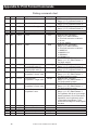
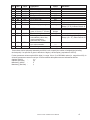
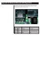
E1070 e-tools Software
TM
E1070 e-toolsTM
User Instructions
ENGLISH
43127-0016A e1
May 22, 2006
*43127-0016*
E1070ETOOLS_REV2006_U.P65
2
E1070 e-toolsTM Software User’s Manual
Table of Contents
Table of Contents ..............................................................................................................3
Minimum system requirements ................................................................................... 4
Introduction ....................................................................................................................... 5
Starting e-tools .................................................................................................................. 5
Command Bar ............................................................................................................. 7
Menu Bar .................................................................................................................... 8
Configuration Window ............................................................................................... 9
Entering Values .......................................................................................................... 9
Creating and Downloading a Configuration File ............................................................. 10
Setting the Defaults .................................................................................................. 10
Setting Options ......................................................................................................... 10
CONFIGURING - Configuration Button .................................................................... 11
Scale Icon ............................................................................................................ 11
Application Icon ................................................................................................... 19
Serial Icon ........................................................................................................... 27
Analog Output Icon (requires indicator option) ................................................... 28
Pulse Counter Icon (requires indicator option) ................................................... 29
Trips Icon ............................................................................................................. 29
CONFIGURING - Printer Button ............................................................................... 30
Creating a Print Format ....................................................................................... 31
CONFIGURING - Net Mange Button ........................................................................ 33
DeviceNetTM ....................................................................................................... 34
PROFIBUS® ......................................................................................................... 35
ControlNet® (requires indicator option) ............................................................... 36
EtherNet-1 (IT) .................................................................................................... 37
EtherNet-2 (Modbus/TCP) .................................................................................. 38
EtherNet-3 (Modbus/IP) ...................................................................................... 39
Remote I/O .......................................................................................................... 40
EtherNet-4 (IT Server) ......................................................................................... 41
Saving the File .......................................................................................................... 42
Downloading a File ................................................................................................... 42
Uploading a File ........................................................................................................ 43
Downloading Firmware ............................................................................................. 44
Appendix A: Print Format Commands ............................................................................ 46
Appendix B: Mainboard Network LED Diagnostics ......................................................... 48
Appendix C: Network Tokens ......................................................................................... 49
E1070 e-toolsTM Software User’s Manual
3
Minimum system requirements
To install this software you need a computer with the following minimum specifications:
• PC with Microsoft® Windows ME, 2000, XP
• Pentium III processor @ 700 MHz
• 128 MB RAM
• 20 MB of hard drive space
• CD ROM drive
• RS-232 communication port or USB to serial converter
4
E1070 e-toolsTM Software User’s Manual
Introduction
Welcome to the Avery Weigh-Tronix® e-toolsTM software manual. This
software makes configuration of the EvolutionTM series of indicators a quick,
PC based operation.
This document is meant to help you understand what this software is
capable of and how to use it effectively with your model E1070 indicator.
The Evolution series of indicators are configurable through the front panel
and a menu structure built into the indicator’s software. The e-tools program
makes this front panel configuration unnecessary.
Easy, on-screen check boxes, drop down lists and data entry boxes make
configuration quick. When done, you download the file you create to the
indicator via RS-232 serial cable. The new program overwrites the configuration settings in the indicator with your new ones. You can save the configuration file for use on multiple indicators or as a backup for your system.
You can also upload the configuration of an indicator into the program and
modify it.
Below is a small list of the items you can enable and configure with this
software:
• Capacity
• Division size
• Zero and Motion parameters
• Units of measure
• Serial communication
• Networks
• Applications
• Inputs
• Outputs
• Print formats
Starting e-tools
After installation, covered in the Getting Started manual, click on
START>PROGRAMS>Avery Weigh-Tronix>etools.
The program will start and you will see the following window:
Choose your indicator model from this drop down box.
Choose E1070 for this manual, then click on Run.
E1070 e-toolsTM Software User’s Manual
5
The following window is displayed:
If you click on the Avery
Weigh-Tronix logo, the AWT
web site will open.
Site Selector
Command Bar
Tool Bar
Menu Bar
Configuration
Window
Status Bar
The screen is divided into several parts:
The command bar has drop down lists for you to choose from when you
click on the words.
The tool bar lets you:
• start a new file
• open an existing file
• save a file
• print a file
• open the Options dialog box
• upload a configuration file
• download a configuration file
The menu bar contains icons you can click on to show the configuration
items for your indicator.
The configuration window will show the current configuration items to be
set.
The status bar at the bottom of the window shows the status of several
keyboard keys and the current date and time.
Those items needing further explanation are explained in detail in the
following sections.
6
E1070 e-toolsTM Software User’s Manual
The command bar has the following commands:
Command Bar
File
If you click File the following drop down menu appears:
From this list you can:
• create a new file
• open an existing file
• close an open file.
• upload a configuration file from an indicator
• download a configuration file to an indicator
• save an open file
• save an open file under a different name
• setup the printing or a configuration report
• print a configuration report
• choose from a list of recent files
• close the program
View
If you click View the following drop down menu appears:
Click Toolbar to toggle the toolbar on and off
Click Status Bar to toggle the status bar on and off
Tools
If you click Tools the following drop down menu appears:
Click here to open the Options dialog box
Click here to print a configuration report
Click here to clear recent files
Help
If you click Help the following drop down menu appears:
Click here to open the user’s manual (PDF)
Click here to see software information
E1070 e-toolsTM Software User’s Manual
7
Menu Bar
8
As you click on each menu bar item, the related icons appear. All four menu
items are shown below. Each icon will be covered in the Configuration
section of this manual.
E1070 e-toolsTM Software User’s Manual
Configuration Window
When you click on a menu bar icon, the related configuration dialog box
appears in the configuration window. Below is an example:
It is in these dialog boxes that you choose all the configuration parameters
for your indicator and scale setup.
When all your parameters are set, you connect your PC serial port to the
serial port of the indicator and click the download (down arrow) button on
the button bar. The file is sent to the indicator and all the new parameters
take effect.
Entering Values
When you key in values, the software validates the entry so that you cannot
enter an incorrect value. For example, if a percentage rate (say 0-100) is
required, and you key in 123, then the value will be highlighted and you will
not be able to tab to the next input box until the value is corrected. This will
also occur if you enter an invalid character, such as '12w' instead of '123'.
You can either edit and correct the value or (while the entire value is highlighted) you can press the DELETE key and start over. If the entry box is
completely clear and you tab to another box, the default value for that item
will automatically be inserted in the box.
E1070 e-toolsTM Software User’s Manual
9
Creating and Downloading a Configuration File
The steps you take to create a new configuration file are:
You can edit an existing file by
opening the file, making the
desired changes and saving
the file.
Setting the Defaults
• set the defaults
• configure all scale/indicator parameters
• save the file
• download the file to the indicator
Use this item, in the upper right corner of the program window, to choose
your instrument location; NA (North America), EU (Europe). Choosing the
correct one will set defaults to your location’s requirements.
Choose the location where the indicator will be used. Choosing the correct
one will set defaults to your location’s requirements.
Setting Options
Click on Tools>Options to see the General tab shown below:
General tab
In the this window you can enable or disable the following options:
Beeper
This is a PC warning beep when an error is detected.
Sound Effects
These are the sounds made as you navigate the e-tools
program.
Load last…
If enabled, the last saved file will open when the e-tools
program is started.
Allow selection… If enabled you can select a firmware bootloader under
the Firmware menu bar item.
Prevent Screen… This will disable the screensaver to stop it from interrupting the download process.
10
E1070 e-toolsTM Software User’s Manual
RS-232 COM tab
Click the RS-232 COM tab.
Choose the serial port through which your computer will download the files.
Set a timeout for how long the system will try to download before the attempt
is aborted.
CONFIGURING Configuration Button
Under the Configuration button on the menu bar there are six icons:
• Scale
• Applications
• Serial
• Analog out
• Pulse Counter
• Trips
Each is explained in detail below.
Scale Icon
Click on the Scale icon and the following dialog box appears:
The dialog box has several tabs. Each tab is explained below.
E1070 e-toolsTM Software User’s Manual
11
Calibration tab
Under the Calibration tab, type in, select or enable the following items:
Capacity
Type in the scale capacity.
Weight
Type in the calibration test weight size
Calibration Units Choose lb or kg as the calibration unit of measure
Division
Type in the division size of your displayed weight.
Choices are: 1, 2, 5, 10, 20, 50, 100, 200, 500, 1/2, 2/5,
5/10, 10/20, 20/50.
The fraction choices are for use as dual range divisions.
The first number is the division size for the first half of
the capacity and the second number is the division size
for the 2nd half of the capacity.
All of these capacities function in conjunction with the
decimal place position. For example, if you choose a
division size of 5 and a decimal position of 12345.6,
your division size will be .5.
Decimal Pos.
Pick a decimal position from the drop down list. Choices
available are; 123456, 12345.6, 1234.56, 123.456,
12.3456 and 1.23456.
Decimal position works with Division size. Pick a
division size then the decimal position to get the displayed division size.
Weight Source
Choose if your scale is analog or SensorComm. If you
choose SensorComm the following appears in the
window:
When using a scale with
SensorComm, always start
with B1 and continue consecutively, i.e. B2, B3, etc.
You must enable the sensors which will be used by
SensorComm. You may also enable ghosting which
allows the scale to function in certain situations with 1 or
more weight sensors out of operation. See the SensorComm manuals for complete information.
12
E1070 e-toolsTM Software User’s Manual
Units Enabled
Enable the units of measure you want available when
you click on the indicator’s UNITS key. The shaded unit
under Units Enabled is a result of the selection in
Calibration Units.
If Custom is checked under Units Enabled, the dialog
box changes to this:
If your new custom unit is
larger than one CAL UNIT,
then you key in how many CAL
UNITS make up 1 new custom
unit. For example 1 TON =
2000 pounds so with pounds
selected as our CAL UNIT we
would key in 2000 for the
multiplier.
one cal unit
number of custom units
If your new custom unit is
smaller than one CAL UNIT,
then you divide one cal unit by
the number of custom units it
takes to make up a single CAL
UNIT. Multipliers are limited to
a total of seven digits by the
display.
Custom Units
Type a name for the custom unit of measure. Type in a
conversion factor based on the primary or calibration
unit of measure. See the large note in the left column of
this page.
Example #1:
16 ounces = 1 pound.
Do the math:
(one cal unit / number of
custom units = the multiplier)
1/16=0.0625
So with pounds selected as our
CAL UNIT we would key in
0.0625 for the multiplier.
Example #2:
1000 Grams = 1 KG.
Do the math:
(one cal unit / number of
custom units = the multiplier)
1/1000=0.001
So with KG selected as our
CAL UNIT we would key in
0.001 for the multiplier.
E1070 e-toolsTM Software User’s Manual
13
Zero/Motion tab
The following is displayed when you click on the Zero/Motion tab.
Under the Zero/Motion tab, set the following:
Zero Range
Type in a percentage of capacity, within which the
ZERO key will zero the scale.
Center Zero Range Select a window size for the center-of-zero annunciator. You can choose between ±¼ and ±½ division of
zero weight. When the weight falls within the window
size, the center-of-zero annunciator lights.
Gross Zero Band
AZT and Motion
Common Division selections:
0.25
0.5
1.0
2.0
3.0
14
This is a parameter used to trigger the tare clear
function covered under the Tare tab. You can select
values between 0 and 100 divisions.
Auto Zero Tracking Type in a division size and time delay in seconds. The
division size you pick defines a range above and
below zero. When scale weight is inside this range for
the number of seconds you picked, ½ of the weight
will be zeroed. The indicator will repeat removing ½
the weight every X seconds. X being the number of
seconds you have picked. See note at left.
Motion
Type in a division size and time delay in seconds.
This defines the stability window in terms of ±divisions
for a period of time, in seconds. If a weight changes
less than this number of divisions in the time period
you select, the motion light turns off and the weight is
considered stable. See note at left.
E1070 e-toolsTM Software User’s Manual
Tare/E-Mail tab
The following is displayed when you click on the Tare/E-Mail tab:
Here you can set the following:
Pushbutton Tare
If you enable this item you can use the TARE key to
tare a weight from the scale. If you disable this item,
you cannot tare using the TARE key.
Auto Tare Clear
If you enable this item the tare will be automatically
cleared when the weight falls below the value set
under Gross Zero Band discussed on the previous
page.
Keyboard Tare
If you enable this item you can key in a tare weight
and press the TARE key to activate the tare value.
Preset Tare
If you enable this item you can use a tare that is held
in the PLU memory channels.
Send Email When: Select any or all instances when an email notice is
sent by the indicator. Email is setup in the Networks
window.
E1070 e-toolsTM Software User’s Manual
15
System tab
The following is displayed when you click on the System tab:
Auto Print Enable Use this item to set a minimum weight under which the
indicator will send out the configured print format. This
is a percentage of scale capacity.
Error Indicator
Choose the function that is associated with the bottom
LED error indicator on the display. Choices are Off,
SensorComm, Network-1 or Network-2.
Deadload Enable If you enable this, the Deadload choices appear in the
bottom right of the window. Use these items to choose a
percentage of scale capacity at which the scale gives a
warning or causes an error. This is used if SensorComm is enabled.
Display
Update Rate - Set the display update rate. Choices are
1, 2, 5, 10 Hz.
Separators -
Pick a decimal point or a comma for the
fraction delimiter for the display. For
example, if you pick Decimal, the display
will show 10.5. If you pick Comma, the
display will show 10,5.
Time/Date Format Time - Choices are 12 hour (AM/PM) or 24 hour
format.
Date - Select the style of date display. Choices are
shown below:
16
E1070 e-toolsTM Software User’s Manual
Filter tab
Three-pole filtering is faster
response to weight in a short
time.
Single-pole, passive filtering is
slower response to weight in a
longer time period with improved accuracy.
Click the Filter tab and the following is displayed.
Averages
Set the number of A to D counts to be averaged for
display or printed weight. Choose values between 0 and
100 from the drop down list.
Filter enable
Choose disable to disable filtering or choose single pole
or three pole filtering. See note at left.
Filter settings
If you enable filtering Filter Settings appears. For the
Constant value you can pick a value between 1 and 10.
Set the number low for small vibration problems and
higher for more dampening effect.
The Threshold Weight parameter causes the indicator
to respond quickly to large weight swings. Threshold is
the amount of weight swings, in calibration units,
beyond which the filtering will be temporarily disabled.
For example, if you set this to 10 lbs, a weight swing
greater than 10 pounds occurring during the sample
time will disable the filtering until the weight swings
during the sample time is less than 10 lbs.
E1070 e-toolsTM Software User’s Manual
17
Ranges tab
Click the Range tab and the following is displayed:
Use this item to set the point at which under range (lower) dashes or over
range (upper) dashes are displayed. You can choose between 105% of
capacity or 9 divisions over capacity.
This completes the Scale section of the configuration.
18
E1070 e-toolsTM Software User’s Manual
Application Icon
Click the Application icon on the Menu Bar and the following window appears:
These tabs give you access to each application which you can enable. If
enabled, some applications may have more settings. Each are discussed
below.
General Weighing tab
General weighing is the first tab that appears since it is the default application on the E1070. It is enabled automatically since it is the default application.
Choose Print Format(s):
Type in the print formats (0-10) that you want printed when the PRINT
button is pressed during normal operation. Multiple print formats must be
typed in ascending order.
For example: Enter 0123410 and print formats 0, 1, 2, 3, 4 and 10 are sent
out the serial port.
Accumulator tab
Click on the Accumulator Tab. Enable this application by clicking on the
Enable button.
Choose Print Format(s):
Type in the print formats (0-10) that you want printed when the PRINT
button is pressed during normal operation. Multiple print formats must be
typed in ascending order.
For example: Enter 0123410 and print formats 0, 1, 2, 3, 4 and 10 are sent
out the serial port.
E1070 e-toolsTM Software User’s Manual
19
Batching tab
Click the Batching tab and select Enable Batching Applications. The following choices will appear:
Choose Print Format(s):
Type in the print formats (0-10) that are to be printed when the PRINT
button is pressed during normal operation. Multiple print formats must be
typed in ascending order.
For example: Enter 0123410 and print formats 0, 1, 2, 3, 4 and 10 are sent
out the serial port.
Select Automatic, Manual, Filling or Continuous Mode:
Manual
If the recipe is set up for Manual mode, you press the
F1 key to start the batch and you need to press the F1
key each time a output is reached to activate the next
ingredient output.
To terminate the filling process,
press the F1 key. All outputs
will turn off, and the process
will start over when the F1 key
is pressed again.
Automatic
If the recipe is set up for Automatic mode, you press the
F1 key to start the batch and each output is activated
and deactivated automatically by the indicator.
Filling
In Fill mode, any recipe that has been setup is ignored.
The filling process is run based on the values set for the
outputs. In order to complete the filling process, at least
one output must be enabled.
Continuous
Continuous batching mode. This mode is very close to
the Auto mode. In continuous mode, another batch is
started immediately after the previous batch has finished. In Auto mode, the user must press the F1 key to
start each batch.
Press the F1 key to start the filling process.
1. a. If output 1 is enabled, and the net weight on the scale is below the
value of the output, output 1 will come on.
b. If output 2 is enabled, and the net weight on the scale is below the
value of the output, output 2 will come on.
c. If output 3 is enabled, and the net weight on the scale is below the
value of the output, output 3 will come on.
2. Each output will remain on until its output value is met.
3. The filling process can be restarted by pressing the F1 key.
20
E1070 e-toolsTM Software User’s Manual
Select Recipe Number:
When you pick a recipe number the following appears in the window:
You can now create a recipe using this Recipe area of the screen.
Choose Type of Recipe:
Constant
Batches are all the same size and the weight of each
ingredient is predetermined by the recipe.
Percentage
Batch size is chosen by the operator and each ingredient is determined by the percentage set in the recipe.
Gross
You set the gross weight at which each ingredient will
stop. The ingredient is complete when the gross weight
on the scale reads the value that was set, regardless of
the weight on the scale when the batch was started.
Enable or disable the Preact:
A preact is the time it takes an ingredient (which is falling from an auger or
other feeder) to reach the scale after the auger or feeder is shut off. There
will always be material in “free-fall” after an ingredient is shut off and the
indicator will automatically calculate this and update this value.
The first time a batch is run, overage for any ingredient weight is calculated
and the next time the ingredient is being weighed the output will be shut
down so approximately 70% of the overage is reduced. This occurs each
time a batch is run so that the system quickly learns and produces accurate
batches.
Define the ingredients:
To define an ingredient you:
• Choose an ingredient #.
• Choose the basis for the ingredient:
The Basis of each ingredient can be weight, time or pulse counts.
Scale
If an ingredient basis is scale weight, the output activates at the appropriate time and deactivates when the
weight set in the recipe is reached.
Time
If an ingredient basis is time, the output activates for the
time set in the recipe and then deactivates.
Counts
If an ingredient basis is counts from a pulse counter, the
output activates for the number of pulse counts set in
the recipe and then deactivates.
• Choose an Output: Set the output you want associated with the ingredient. Choices are 1, 2 , 3 or None.
• Choose a Delay: Set a time delay between when a basis is met and the
next ingredient action is started.
E1070 e-toolsTM Software User’s Manual
21
Checkweigher tab
Click the Checkweigher tab and select Enable Checkweigher Application.
The following choices will appear:
Choose Print Format(s):
Type in the print formats (0-10) that are to be printed when the PRINT
button is pressed during normal operation. Multiple print formats must be
typed in ascending order.
For example: Enter 0123410 and print formats 0, 1, 2, 3, 4 and 10 are sent
out the serial port.
Enable or disable the checkweigher graph on the indicator display.
Choose Limits or Sample mode:
22
Limits Mode
User enters the upper and lower limits for the item and
the indicator will use those values to run the display.
See illustration below. Each graduation equals one
division by default but, this can be changed in the
Display Graduation box.
Sample Mode
If you pick Sample Mode, the Target Window box,
shown below, appears in the dialog box.
E1070 e-toolsTM Software User’s Manual
User places a correct weight “product” on the scale and
presses the F1 key. The indicator will use this weight to
run the display. Upper and lower limits will automatically
be one division above and below the target weight
respectively, by default. This default vaule can be
changed using the Target Window. Type in a target
division size other than the default, 1. Each fan graph
segment is equal to 1 scale division but, this can be
changed in the Display Graduation box.
The TARGET light stays lit if weight is within the upper
and lower limits.
Configure Outputs: Choose between Standard and Target.
Standard: Configure the outputs using the F1 key and keying in
the OP1, OP2 and OP3 values.
Target:
Outputs are set according to the selected target
weights. Output 1 activates when the Under condition is
met. Output 2 activates when the Accept condition is
met and Output 3 activates when the Over condition is
met.
Display Graduations: Chose how many divisions each fan graph segment is
equal to.
E1070 e-toolsTM Software User’s Manual
23
Counting tab
Click the Counting tab and select Enable Counting Application. The following
choices will appear:
Choose Print Format(s):
Type in the print formats (0-10) that are to be printed when the PRINT
button is pressed during normal operation. Multiple print formats must be
typed in ascending order.
For example: Enter 0123410 and print formats 0, 1, 2, 3, 4 and 10 are sent
out the serial port.
Choose a Sample Mode:
Bulk sampling
In this sampling method you place the specified sample
number of items on the scale all at once (in bulk) and
after motion stops, the scale automatically starts to
calculate piece weight and then shows the count.
Dribble sampling In this sampling method you can count out the specified
sample number of items onto the scale and when you
are ready, press the F1 key and after motion stops, the
scale starts to calculate piece weight and then shows
the count.
Choose the Sample Minimum Weight and the Sample Size:
Set the minimum sample weight as a percent of capacity that the sample
must weigh.
Set the default sample size to prompt the operator to place on the scale.
24
E1070 e-toolsTM Software User’s Manual
Peak-Hold tab
Click the Peak-Hold tab and select Enable Peak-Hold Application. The
following choices will appear:
Choose Print Format(s):
Type in the print formats (0-10) that are to be printed when the PRINT
button is pressed during normal operation. Multiple print formats must be
typed in ascending order.
For example: Enter 0123410 and print formats 0, 1, 2, 3, 4 and 10 are sent
out the serial port.
Remote Display tab
Click the Remote Display tab and if you enable it you will see the following
choice:
Choose Print Format(s):
This section for future use
E1070 e-toolsTM Software User’s Manual
25
Choose Remote Display Mode:
Mode-1
The indicator acting as the remote display will show the Gross
or Net annunciator and the characters displayed on the master
indicator.
Mode-2
The remote display will show the Gross or Net annunciator, the
characters and all annunciators displayed on the master indicator.
Mode-3
The remote display will show the Gross or Net annunciator, the
characters displayed on the master indicator and allows zeroing
of the scale from the remote.
Mode-4
The remote display will show the Gross or Net annunciator, the
characters and annunciators displayed on the master indicator
and allows full function of all the keys on the remote.
Choose a Port: Choose which port, 1 or 2, serial information is coming into.
This concludes the Application Icon section.
26
E1070 e-toolsTM Software User’s Manual
Serial Icon
Click the Serial icon on the Menu Bar and the following window appears:
In this window you set up the serial communication parameters for Port 1
and Port 2. Choose the port and then select values for each item from its
drop down list.
Baud Rate
Data Bits
Parity
Handshake
Mode
Choose from 300 to 115200
Choose from 7 or 8
Choose from None, Odd or Even
Choose from None, RTS/CTS or Xon/Xoff
Depending on the mode you pick, a secondary choice may
appear. All are explained below:
Broadcast
You must type in the print
format numbers in ascending
order.
Enquire
For example: Enter 0123410
and print formats 0, 1, 2, 3, 4
and 10 are sent out the serial
port.
SMA
RD4100
RD Mode 1
RD Mode 2
Causes a Print Format box and Rate box to
appear. Choose Broadcast to cause the
configured print format(s) to be sent out the
serial port continuously at the rate chosen
when there is no motion on the scale
Causes a Print Format box and Polling
Character box to appear. Choose the polling
character which when received by the indicator will cause the print format(s) to be sent
through the serial port. The polling character
can be any ASCII code # from 0 to 255 (hex
00 to FF).
Choose from the Scale Manufacturer’s
Association list of commands and responses
in Appendix 1 of this manual.
Like Broadcast except it will send information
even when the scale is in motion. If you pick
format #0, a default G XXXXXX lb format will
be sent.
Select this to send G XXXXXX lb at the rate
you pick in the Rate box.
Select this to send the same as RD Mode 1 +
annunciators
E1070 e-toolsTM Software User’s Manual
27
Select this to send the same as RD Mode 1 +
will accept the keys presses from the remote
(TARE, SELECT, ZERO, PRINT, UNITS)
Select this to send the same as RD Mode 2 +
accepts the keys presses from the remote
(TARE, SELECT, ZERO, PRINT, UNITS)
When you choose this a Muli-drop Address
box appears. The address can be any ASCII
code # from 0 to 255 (hex 00 to FF).
RD Mode 3
RD Mode 4
RS-485
When you choose this a Muli-drop Address
box appears. The address can be any ASCII
code # from 0 to 255 (hex 00 to FF).
485 HD
There is also two checkboxes:
Analog Output Icon
(requires indicator option)
Use Leading Zeros
Leading zeros fill in any open spaces before a
weight value in a printout
Enquire Motion
If checked, the scale will respond to an enquire
code only when there is no motion on the scale.
Click the Analog Output icon on the Menu Bar. If you enable analog output
the following window appears:
Set the Basis:
Choose what the output will be based one; Gross Weight or Net Weight
Set the “Weight for Analog Output”:
For Example: The minimum weight is 0 pounds and the maximum weight is
5000 lbs. This represents the minimum 4mA output at 0 pounds and the
maximum 20mA output at 5000 lbs.
Set the “Output Adjustment”:
For Example: Increasing the offset amount above 0% will increase the 0
weight value. Increasing the span percentage will increase the maximum
weight value. Both of these adjustments increase the voltage from the
physical card.
28
E1070 e-toolsTM Software User’s Manual
Pulse Counter Icon
(requires indicator option)
Click the Pulse Counter icon. If you enable the pulse counter you will see the
window shown below.
You need to set the ratio.
Set the ratio:
Enter the ratio of pulses/calibration unit of measure. For example: You have
a device which pulses 3,000 times / gallon of water. Water weighs approximately 8 lbs/gallon. Your equation would be 3000/8 = 375. This is the value
to enter in the Ratio box.
Trips Icon
Choice
None
F1_Key
Tare
Units
Print
Tare Can.
Start
Stop
Click the Trips icon. Use this to enable and assign key functions to specific
inputs and to enable or disable outputs. Below is a sample of all inputs
enabled and an action assigned to each input. See list of choices in left
margin.
Input Action
No action
Remote F1
Remote TARE key
Remote UNITS key
Remote UNITS key
Clear active tare
Starts batch in
batch mode
Stops batch in
batch mode
When you click the Outputs tab you are shown three checkboxes for the
three outputs. See example below. Click on the checkbox for the output you
want to enable. Click again to disable an output.
E1070 e-toolsTM Software User’s Manual
29
CONFIGURING Printer Button
When you click the Printer button in the Menu Bar and then click the Print
Format icon you will see the screen shown below. Use this window to create
and save custom print formats.
Print Format 0 is the default
print format reserved for each
application mode.
Formats 1-9 are available for
any application mode.
Format 10 - Format 0 for the
General Weighing mode
Format 11 = Format 0 for the
ACC mode
Format 12 = Format 0 for the
Batch mode
Format 13 = Format 0 for the
Target mode
Format 14 = Format 0 for the
Count mode
Format 15 = Format 0 for the
Top mode
Click on the new file icon to start a new print format.
The screen should look similar to this:
Editing Window
30
E1070 e-toolsTM Software User’s Manual
The print format command bar is illustrated below with explanations for the
functions of each.
Duplicates what these six keys
do plus assigns default insert
when ENTER key is pressed
on your keyboard
Duplicates what
these two keys do
Opens a new
format
Cut
Creating a Print Format
Copy
Paste
Inserts
selected
term
Deletes Move
selected insert
term pointer to
end
Show
strings
Show
tokens
To create a print format, follow these steps:
1. Choose a format # from the drop down list above the editing window.
2. Type a print format name in the Name window.
3. Pick a port to use when printing the format.
4. Click on Edit>Enter Key. . .and select what pressing the ENTER key on
the keyboard will insert. See illustration below.
E1070 e-toolsTM Software User’s Manual
31
5. Insert the text cursor in the editing window by clicking anywhere in the
window.
Print Format 0 is the default
print format reserved for each
application mode.
6. Expand the terms list by clicking on the plus (+) symbol.
Formats 1-9 are available for
any application mode.
Format 10 - Format 0 for the
General Weighing mode
Format 11 = Format 0 for the
ACC mode
Format 12 = Format 0 for the
Batch mode
Format 13 = Format 0 for the
Target mode
Format 14 = Format 0 for the
Count mode
Format 15 = Format 0 for the
Top mode
7. Double click a term to insert it at the cursor position or click on a term
and click the Insert Term button.
8. Press the ENTER key when necessary to enter the carriage returns and/
or line feeds you picked in step 4. See sample below:
9. When you are finished laying out the look of the format you can go to
the next format you want to create or continue with creating your configuration file.
32
E1070 e-toolsTM Software User’s Manual
CONFIGURING Net Mange Button
These files are needed to configure the PLC so it will communicate to the E1070 indicator:
PROFIBUS® - AWTX0913.GSD
When you click the Net Manage button and the Fieldbus-1 icon in the Menu
Bar you will see the screen shown below. Use this window to configure your
network connections, if any.
You can choose from Fieldbus-1 or Fieldbus-2. With either of these you can
configure the networks shown in the illustration below:
DeviceNetTM E1070_Dnet_EnetIP.EDS
ControlNet®ABS_CNT_V_1_5.EDS
EtherNet-3 (EtherNet/IPTM) E1070_Dnet_EnetIP.EDS
These files can be found in the
etools folder on your hard drive.
Typically this is C:\program
files\avery weigh-tronix\etools\networks.
Pick the network from the drop down list and the appropriate boxes will
appear and/or appropriate tab(s) will activate. Follow the steps in the next
pages to configure each network.
E1070 e-toolsTM Software User’s Manual
33
Click on DeviceNetTM in the drop down list to configure a DeviceNet network.
The window looks like this:
DeviceNetTM
Valid nodes for DeviceNet are
0 to 63.
If an address greater than 63 is
used, the indicator will set the
node to 63 after the download.
Select Indicator node:
Key in the node for the indicator. Acceptable values are 0 to 63. See note at
left.
Select Baud Rate:
Select a baud rate for network communications. Available choices are 125K,
250K and 500K.
Click the Map Data tab and the following is displayed:
This shows the
“spacing” of each
piece of data as it
will show up on
the PLC.
Choose to create the
Inbound Data Map or
Outbound Data Map
by selecting your
choice here.
Click here for a
drop down list of
network tokens.
See Appendix C
for full list.
Choose Endian Format
(Big or Little) here.
Click here to
trade/swap the
word order
Click here for a
drop down list of
Data Types.
Data Type
Type #
S8
0
# of Bytes
Range of Value
Signed Char.
Data
1
-127 to 127
U8
1
Unsigned Char.
1
0 to 255
S16
2
Signed Integer
2
-32767 to 32767
U16
3
Unsigned Integer
2
0 to 65535
S32
4
Signed Long
4
-2,147,483,647 to 2,147,483,647
U32
5
Unsigned Long
4
0 to 4,294,967,295
FLOAT
6
Float
4
1.0E-37 to 1.0E37
34
E1070 e-toolsTM Software User’s Manual
This shows the total
number of bytes used by
the indicator. This
information is required
by the PLC programmer
and is automatically
calculated.
Click on PROFIBUS® in the drop down list to configure a PROFIBUS®
network. The window looks like this:
PROFIBUS®
Valid nodes for PROFIBUS are
0 to 63.
If an address greater than 63 is
used, the indicator will set the
node to 63 after the download.
Select indicator node:
Key in the node for the indicator. Acceptable values are 0 to 63. See note at
left.
Click the Map Data tab and the following is displayed:
This shows the
“spacing” of each
piece of data as it
will show up on
the PLC.
Choose to create the
Inbound Data Map or
Outbound Data Map
by selecting your
choice here.
Click here for a
drop down list of
network tokens.
See Appendix C
for full list.
Choose Endian Format
(Big or Little) here.
Click here to
trade/swap the
word order
Click here for a
drop down list of
Data Types.
Data Type
Type #
S8
0
# of Bytes
Range of Value
Signed Char.
Data
1
-127 to 127
U8
1
Unsigned Char.
1
0 to 255
S16
2
Signed Integer
2
-32767 to 32767
U16
3
Unsigned Integer
2
0 to 65535
S32
4
Signed Long
4
-2,147,483,647 to 2,147,483,647
U32
5
Unsigned Long
4
0 to 4,294,967,295
FLOAT
6
Float
4
1.0E -37 to 1.0E37
E1070 e-toolsTM Software User’s Manual
This shows the total
number of bytes used by
the indicator. This
information is required
by the PLC programmer
and is automatically
calculated.
35
ControlNet®
(requires indicator option)
Click on ControlNet in the drop down list to configure a ControlNet network.
The window looks like this:
Valid nodes for ControlNet are
0 to 63. Node zero is reserved
for hardware addressing (i.e.
switch settings) done on the
PC-card for this fieldbus
interface.
If an address greater than 63 is
used, the indicator will set the
node to 63 after the download.
Select Indicator node:
Key in the node for the indicator. Acceptable values are 0 to 63. See note at
left.
Click the Map Data tab and the following is displayed:
This shows the
“spacing” of each
piece of data as it
will show up on
the PLC.
Choose to create the
Inbound Data Map or
Outbound Data Map
by selecting your
choice here.
Click here for a
drop down list of
network tokens.
See Appendix C
for full list.
Choose Endian Format
(Big or Little) here.
Click here to
trade/swap the
word order
Click here for a
drop down list of
Data Types.
Data Type
Type #
S8
0
# of Bytes
Range of Value
Signed Char.
Data
1
-127 to 127
U8
1
Unsigned Char.
1
0 to 255
S16
2
Signed Integer
2
-32767 to 32767
U16
3
Unsigned Integer
2
0 to 65535
S32
4
Signed Long
4
-2,147,483,647 to 2,147,483,647
U32
5
Unsigned Long
4
0 to 4,294,967,295
FLOAT
6
Float
4
1.0E-37 to 1.0E37
36
E1070 e-toolsTM Software User’s Manual
This shows the total
number of bytes used by
the indicator. This
information is required
by the PLC programmer
and is automatically
calculated.
EtherNet-1 (IT)
Click on EtherNet-1 (IT) in the drop down list to configure a EtherNet-1 (IT)
network. The window looks like this:
Select Indicator IP Address:
Key in the IP address for the indicator. If you enable DHCP (Dynamic Host
Configuration Protocol), the IP address for the indicator is not required.
DHCP (Dynamic Host Configuration Protocol) is a protocol for
assigning dynamic IP addresses to devices on a
network.
Select Ethernet Addresses:
Key in the IP address for the host IP, SMTP, Gateway, Subnet and key in
the port number that the indicator and the remote host will be connected on.
Set Socket Mode:
SMA – the SMA protocol over the Ethernet connection. This is the exact
same protocol used on the serial ports. See the Service-Serial section of
the E1070 Service Manual for details.
Polled – If Polled is chosen you will be prompted to select a polling character. Choices from 0 to 255. When the polling character is received on the
Ethernet connection, the indicator will act as if the PRINT key has been
pressed (all of the formats-to-print will be sent out of the configured port). If
you want the print format(s) to be sent back on the Ethernet connection, the
print formats must be configured for tcpip1 (net1) or tcpip2 (net2).
Click the SMTP tab and the following is displayed:
Key in the User
Name for the
indicator.
Key in the Domain
Name for the
indicator.
Key in the email
address for the
indicator.
Key in the email
recipient’s address.
Key in the subject
of the email.
E1070 e-toolsTM Software User’s Manual
37
EtherNet-2 (Modbus/TCP)
Click on EtherNet-2 (Modbus/TCP) in the drop down list to configure a
EtherNet-2 (Modbus/TCP) network. The window looks like this:
Select Indicator IP Address:
Key in the IP address for the indicator.
Gateway:
Key in the Gateway.
Subnet:
Key in the Subnet.
Click the Map Data tab and the following is displayed:
This shows the
“spacing” of each
piece of data as it
will show up on
the PLC.
Choose to create the
Inbound Data Map or
Outbound Data Map
by selecting your
choice here.
Click here for a
drop down list of
network tokens.
See Appendix C
for full list.
Choose Endian Format
(Big or Little) here.
Click here to
trade/swap the
word order
Click here for a
drop down list of
Data Types.
Data Type
Type #
# of Bytes
Range of Value
S8
0
Signed Char.
Data
1
-127 to 127
U8
1
Unsigned Char.
1
0 to 255
S16
2
Signed Integer
2
-32767 to 32767
U16
3
Unsigned Integer
2
0 to 65535
S32
4
Signed Long
4
-2,147,483,647 to 2,147,483,647
U32
5
Unsigned Long
4
0 to 4,294,967,295
FLOAT
6
Float
4
1.0E-37 to 1.0E37
38
E1070 e-toolsTM Software User’s Manual
This shows the total
number of bytes used by
the indicator. This
information is required
by the PLC programmer
and is automatically
calculated.
EtherNet-3 (Modbus/IP)
Click on EtherNet-3 (Modbus/IP) in the drop down list to configure a
EtherNet-3 (Modbus/IP) network. The window looks like this:
Select Indicator IP Address:
Key in the IP address for the indicator.
Gateway:
Key in the Gateway.
Subnet:
Key in the Subnet.
Click the Map Data tab and the following is displayed:
This shows the
“spacing” of each
piece of data as it
will show up on
the PLC.
Choose to create the
Inbound Data Map or
Outbound Data Map
by selecting your
choice here.
Click here for a
drop down list of
network tokens.
See Appendix C
for full list.
Choose Endian Format
(Big or Little) here.
Click here to
trade/swap the
word order
Click here for a
drop down list of
Data Types.
Data Type
Type #
S8
0
# of Bytes
Range of Value
Signed Char.
Data
1
-127 to 127
U8
1
Unsigned Char.
1
0 to 255
S16
2
Signed Integer
2
-32767 to 32767
U16
3
Unsigned Integer
2
0 to 65535
S32
4
Signed Long
4
-2,147,483,647 to 2,147,483,647
U32
5
Unsigned Long
4
0 to 4,294,967,295
FLOAT
6
Float
4
1.0E -37 to 1.0E37
E1070 e-toolsTM Software User’s Manual
This shows the total
number of bytes used by
the indicator. This
information is required
by the PLC programmer
and is automatically
calculated.
39
Click on Remote I/O in the drop down list to configure a remote I/O network.
The window looks like this:
Remote I/O
Valid addresses for Remote I/O
are 0 to 59.
Select Rack information:
Address acceptable values are 0 to 59. See note at left.
If an address greater than 59 is
used, the indicator will set the
address to 59 after the download.
Size can be 1/4, 1/2, 3/4 or Full.
Start Quarter can be First, Second, Third or Fourth.
Last can be NO or YES.
Select Remote I/O settings:
Baud Rate can be 57.6K, 115.2K or 230.4K
Remote I/O mode is Block or Cyclic
Click the Map Data tab and the following is displayed:
This shows the
“spacing” of each
piece of data as it
will show up on
the PLC.
Choose to create the
Inbound Data Map or
Outbound Data Map
by selecting your
choice here.
Click here for a
drop down list of
network tokens.
See Appendix C
for full list.
Choose Endian Format
(Big or Little) here.
Click here to
trade/swap the
word order
Click here for a
drop down list of
Data Types.
Data Type
Type #
S8
0
# of Bytes
Range of Value
Signed Char.
Data
1
-127 to 127
U8
1
Unsigned Char.
1
0 to 255
S16
2
Signed Integer
2
-32767 to 32767
U16
3
Unsigned Integer
2
0 to 65535
S32
4
Signed Long
4
-2,147,483,647 to 2,147,483,647
U32
5
Unsigned Long
4
0 to 4,294,967,295
FLOAT
6
Float
4
1.0E-37 to 1.0E37
40
E1070 e-toolsTM Software User’s Manual
This shows the total
number of bytes used by
the indicator. This
information is required
by the PLC programmer
and is automatically
calculated.
EtherNet-4 (IT Server)
Click on EtherNet-4 (IT Server) in the drop down list to configure an
EtherNet-4 (IT Server) network. The window looks like this:
Select Indicator IP Address:
Key in the IP address for the indicator. If you enable DHCP (Dynamic Host
Configuration Protocol), the IP address for the indicator is not required.
Select Ethernet Addresses:
Key in the IP address for the host IP, SMTP, Gateway, Subnet and key in
the port number that the indicator and the remote host will be connected on.
Set Socket Mode:
SMA – the SMA protocol over the Ethernet connection. This is the exact
same protocol used on the serial ports. See the Service-Serial section of the
E1070 Service Manual for details.
Polled – If Polled is chosen you will be prompted to select a polling character. Choices from 0 to 255. When the polling character is received on the
Ethernet connection, the indicator will act as if the PRINT key has been
pressed (all of the formats-to-print will be sent out of the configured port). If
you want the print format(s) to be sent back on the Ethernet connection, the
print formats must be configured for tcpip1 (net1) or tcpip2 (net2).
Click the SMTP tab and the following is displayed:
Key in the User Name
for the indicator.
Key in the Domain Name
for the indicator.
Key in the email address
for the indicator.
Key in the email
recipient’s address.
Key in the subject of
the email.
E1070 e-toolsTM Software User’s Manual
41
Saving the File
When you have finished configuring all the items you can save the file by
clicking on the File Save button,
, on the Tool Bar. This dialog box is
displayed:
Type in a file name and click Save to save it to the folder of your choice. The
file name does not need to include a file type. E-tools will automatically save
your configuration file as specified by the indicator choice, shown in Save as
type: drop down box.
Downloading a File
Indicator must be unsealed for
a file to be downloaded to it.
See the Service Manual for
details.
The next step in the process is downloading the finished file to your indicator.
1. Connect the PC to the indicator, which requires the configuration, via the
chosen serial communications port on the computer.
2. Click the Download Configuration icon.
3. The following message will be displayed:
4. Verify that the indicator is turned on and in weigh mode.
5. Click Yes to download the indicator configuration. The following screen
will appear and the indicator will display the word bUSy.
42
E1070 e-toolsTM Software User’s Manual
6. Once the download is complete, the window will change to show a Pass
or Fail condition.
7. Once configuration download is complete the indicator is ready to be
calibrated.
Uploading a File
Indicator must be unsealed for
a file to be uploaded from it.
See the Service Manual for
details.
1. To upload an indicator configuration from the indicator to E-tools,
connect the indicator to the PC.
2. Open the E-tools program and click the Upload Configuration button on
the Tool Bar.
3. The following message will be displayed.
4. To upload an indicator configuration from the indicator to E-tools,
connect the indicator to the PC.
5. Open the E-tools program and click the Upload Configuration button on
the Tool Bar. <insert upload icon here>
6. The following message will be displayed:
E1070 e-toolsTM Software User’s Manual
43
7. Once the upload is complete, the window will change to show a Pass or
Fail condition.
8. After uploading the indicator configuration it is recommended to save the
file. Refer to section Saving a File for detailed instructions. The indicator
configuration can now be viewed and edited as needs demand.
Downloading Firmware
This item allows you to download new firmware to the indicator’s microprocessor when needed for proper servicing.
1. Turn off power to the indicator by pressing the power key.
2. Select the Firmware tab in E-tools, then choose Download. The following is displayed:
Be sure to turn off any
screensavers before downloading new firmware or enable the
“Prevent screensaver while
downloading firmware” option
in the TOOLS>OPTIONS
dialog box.
3. Use the Browse button to select the desired version of firmware to
download into the indicator.
4. Use the browser window to find and select the appropriate firmware for
download, then click the Download button.
5. Caution: The user will be warned to check all connections. The indicator uses flash memory, any interruption in power or communications
may damage the flash memory.
44
E1070 e-toolsTM Software User’s Manual
6. Click Cancel to abort firmware download or select OK to download
firmware.
7. After selecting OK, press the power button on the indicator until the file
size is displayed.
8. While downloading firmware, a progress bar appears to indicate file
download.
9. After the download is complete, cycle power on the indicator.
E1070 e-toolsTM Software User’s Manual
45
Appendix A: Print Format Commands
Printing commands chart
Dec
128
HEX
80
Token
GWT(,n)
Application
Gross Weight [1]
Group
Weight
129
81
NWT(,n)
Net Weight [1]
Weight
131
83
SAT(,n)
Semi-Auto Tare [1]
Weight
132
135
136
84
87
88
UN
ID
TIM,x
Units
Scale Serial Number
Time
Weight
Misc
Time
137
89
DAT,x
Date
Date
138
8A
TTV,n
Target Value
Trip
142
8E
CLA(,n)
143
8F
CHA(,n)
144
90
RAV,n
145
91
RTV,n
Active Recipe
Ingredient x ‘Target’ value
Recipe
146
92
RPV,n
Active Recipe
Ingredient x ‘Preact’ value
Recipe
147
93
RIU,n
Active Recipe
Ingredient x units
Recipe
148
149
151
153
155
94
95
97
99
9B
PCE
CNT
GTO
STO
PLU
Piece Weight
Current Count Value
Gross Accumulator
Net Accumulator
PLU NumberData
Count
Count
Weight
Weight
PLU
46
Checkweigher
Checkweight
‘Low Accept’ value [1]
Checkweigher
Checkweight
‘High Accept’ value [1]
Active Recipe
Recipe
Ingredient x ‘Actual’ value
E1070 e-toolsTM Software User’s Manual
Parameter
OPTIONAL, (ASCII)
Range: (‘2’-‘9’), Indicator Default: ‘6’
OPTIONAL, (ASCII)
Range: (‘2’-‘9’), Indicator Default: ‘6’
OPTIONAL, (ASCII)
Range: (‘2’-‘9’), Indicator Default: ‘6’
MANDATORY (DECIMAL)
Range: (0-2), Editor Default:1
0= Format as set/active in indicator
1= hh:mm
2= hh:mm AM/PM
MANDATORY, (DECIMAL)
Range: (0-4), Editor Default:1
0= Format as set/active in indicator
1= MM/DD/YY
2= MM/DD/YYYY
3= DD/MM/YY
4= DD/MM/YYYY
MANDATORY, (HEX #s)
Range: (‘31’-‘33’), Editor Default: ‘1’
For target weights
OPTIONAL, (ASCII)
Range: (‘2’-‘9’), Indicator Default: ‘6’
OPTIONAL, (ASCII)
Range: (‘2’-‘9’), Indicator Default: ‘6’
MANDATORY, (HEX #s)
Range: (‘31’-‘38’), Editor Default: ‘1’
For target weights in recipe
MANDATORY, (HEX #s)
Range: (‘31’-‘38’), Editor Default: ‘1’
For preact values in recipe
MANDATORY, (HEX #s)
Range: (‘31’-‘38’), Editor Default: ‘1’
For target weights in recipe
MANDATORY, (HEX #s)
Range: (‘31’-‘38’), Editor Default: ‘1’
For ingredient units (lb or kg for weight
based ingredients; sec for time based
ingredients; cnts or gallons for pulse
counter based ingredients). To be
printed after the target or actual ingredient value.
Dec
156
162
170
173
178
184
188
189
190
200
HEX
9C
A2
AA
AD
B2
B8
BC
BD
BE
C8
Token
DES
DIS
VER
WST
PUP
PUT
PCT
LST
LGT
DSP(,n)
215
216
D7
D8
NULL
ACT
242
253
F2
FD
PWT
HEX,xx
254
FE
TEX
255
FF
EOS
Application
Group
PLU ID
PLU
Remote Display Status
Miscellaneous
Software Version Number
Miscellaneous
Weight Steady
Weight
Tare associated with the PLU
PLU
PLU Totals Information
PLU
PLU Count Total
PLU
Net Accumulator
PLU
Gross Accumulator
PLU
Print the displayed weight
Weight
Null Token
Print the active value (‘G’ for
gross, ‘N’ for net, ‘T’ for tare)
Peak Hold Weight value
Following number will be
transmitted by value. Also,
use this selection to
transmit a NUL as well.
Reserved for future use
as a ‘token extender’
End of String
Strings
Weight
Weight
Hex-Codes
Parameter
OPTIONAL, (ASCII)
Range: (‘2’-‘9’), Indicator Default: ‘6’
MANDATORY, (ASCII-HEX)
Range: (00 – FF), Editor Default: 00
----String
Notes:
These tokens can be optionally followed by an ASCII 2 to 9 to specify the number of weight digits (including
decimal point). If no specifier is given it defaults to 6 digits (+ decimal point) (equivalent to ASCII 6).
Further, parameter values may be ASCII digits (i.e. range ‘0’ thru ‘9’) or DECIMAL values (i.e. range 0 thru 255). In
all cases, parameters consume one byte. In the term/token table parameters are indicated as follows:
Optional, (ASCII)
(,n)
Optional, (Decimal)
(,x)
Mandatory, (ASCII)
,n
Mandatory, (Decimal) ,x
E1070 e-toolsTM Software User’s Manual
47
Appendix B: Mainboard Network LED Diagnostics
The network LEDs shown in the photo below are found next to the RJ45
Ethernet connector on the main PC board. Below the photo is a table
showing what each LED’s condition means.
LED #4
LED #3
LED #2
LED #1
ON
OFF
LED 1
LINK
ON-LINE
OFF-LINE
LED 2
TX
TRANSMITT ACTIVE
TRANSMITT NOT ACTIVE
LED 3
RX
RECEIVE ACTIVE
RECEIVE NOT ACTIVE
LED 4
SPEED
100M
10M
Appendix C: Network Tokens
Token
Gross
Net
Tare
Peak
Count
PLU Piece weight
PLU number
PLU Gross Accumulator
PLU Net Accumulator
PLU Total counter
PLU Count Accumulator
PLU Tare value
PLU ID
PLU Lower Target weight
PLU Upper Target weight
Recipe Ingredient number
Recipe Ingredient target weight
Recipe Ingredient actual weight
“when target is met
Motion/Weigher Steady
Center of Zero/zero balance
Overload
Underload
Input1-3
Output 1-3
Serial number
Watchdog counter
Remote zero
Remote tare
Remote print
Remote accumulate
Bridge1
Bridge2
Bridge3
Bridge4
Bridge5
Bridge6
Bridge7
Bridge8
Bridge9
Bridge10
Bridge11
Bridge12
Bridge13
Bridge14
Bridge15
Bridge16
Indicator Healthy
Inbound
to net1
X
X
X
X
X
X
X
X
X
X
X
X
X
X**
X**
X**
X**
X**
X**
X**
X**
X**
X**
X**
X**
X**
X**
X**
X**
Outbound
from net 1
X
X
X
X
X
X
X
X
X
X
X
X
X
X
X
X
X
X
X
X
X
X
X
X
X
X
X*
X*
X*
X*
X*
X*
X*
X*
X*
X*
X*
X*
X*
X*
X*
X*
X
Inbound
to net 2
X
X
X
X
X
X
X
X
X
X
X
X
X
X*
X*
X*
X*
X*
X*
X*
X*
X*
X*
X*
X*
X*
X*
X*
X*
* Bridge tokens that are inbound to net2 can be outputs for net1
** Bridge tokens that are inbound to net1 can be outputs for net2
Outbound
from net 2
X
X
X
X
X
X
X
X
X
X
X
X
X
X
X
X
X
X
X
X
X
X
X
X
X
X
X**
X**
X**
X**
X**
X**
X**
X**
X**
X**
X**
X**
X**
X**
X**
X**
X
Token
Token
(decimal value) (hex value)
0
1
2
3
4
5
6
7
8
9
10
11
12
13
14
15
16
00
01
02
03
04
05
06
07
08
09
0A
0B
0C
0D
0E
0F
10
17
18
19
20
21
22
23
24
25
26
27
28
29
30
31
32
33
34
35
36
37
38
39
40
41
42
43
44
45
46
11
12
13
14
15
16
17
18
19
1A
1B
1C
1D
1E
1F
20
21
22
23
24
25
26
27
28
29
2A
2B
2C
2D
2E
Standard Scale & Supply Company
25421 Glendale Avenue
Redford, MI 48239
313-255-6700
www.standardscale.com
Avery Weigh-Tronix USA
1000 Armstrong Dr.
Fairmont, MN 56031 USA
Telephone: 507-238-4461
Facsimile: 507-238-4195
e-mail: [email protected]
www.wtxweb.com
Avery Weigh-Tronix UK
Foundry Lane
Smethwick, West Midlands
England B66 2LP
Tel: +44 870 90 34343
Fax: +44 121 224 8183
Email: [email protected]
Web site:www.averyweigh-tronix.com
Weigh Bar ® is a registered trademark
of Avery Weigh-Tronix and may be
registered in certain jurisdictions.
ODVA™, Ethernet/IP™ and DeviceNet™ are trademarks of ODVA.
PROFIBUS ® is a registered trademark of PROFIBUS International.
Avery Weigh-Tronix Canada, ULC
217 Brunswick Boulevard
Pointe Claire, QC H9R 4R7 Canada
Telephone: 514-695-0380
Toll free: 800-561-9461
Facsimile: 514-695-6820
www.weigh-tronix.ca