1
ACUMEN INSTRUMENTS CORPORATION
DataBridge™ SDR-CF and SDR-OEM-CF
Configuration Guide
revision 1.2 • 08/2007
Copyright
This document is copyrighted by Acumen Instruments Corporation with all rights reserved.
No part of this document may be reproduced in any form without prior written consent of
Acumen Instruments Corporation.
Copyright © 1998-2007 by Acumen Instruments Corporation. All rights reserved.
Disclaimer
This manual has been thoroughly reviewed for accuracy, and every effort has been made to
ensure that the information is accurate and complete. However, different versions of this
product have different features and capabilities, and this manual only reflects one of those
versions. Therefore, Acumen Instruments Corporation assumes no responsibility for errors,
omissions or defects in this material, and shall not be liable for any damages resulting from
their use.
The information in this document is subject to change without notice.
ACUMEN INSTRUMENTS CORPORATION MAKES NO WARRANTY OF ANY KIND WITH RESPECT TO
THIS DOCUMENT, EITHER EXPRESSED OR IMPLIED, INCLUDING WITHOUT LIMITATION ANY
IMPLIED WARRANTIES OF MERCHANTABILITY OR FITNESS FOR A PARTICULAR PURPOSE.
SDR-CF/SDR-OEM-CF Configuration Guide rev 1.2
Configuring the DataBridge SDR-CF
Table of Contents
1. Getting Started ..................................................................... 5
1.1
1.2
1.3
1.4
1.4.1
1.4.2
1.4.3
Overview................................................................................................. 5
Before you start ...................................................................................... 6
A quick guide to the DataBridge SDR ..................................................... 6
Deploying the DataBridge SDR .............................................................. 8
Connecting power to your SDR .............................................................. 8
Connecting to the configuration port ....................................................... 8
Communications software ...................................................................... 8
2. Configuring the DataBridge SDR-CF .................................. 11
2.1
2.2
2.3
2.4
2.5
2.6
Setting date and time ............................................................................ 12
Configuring the data port ...................................................................... 13
Specifying a filename and folder ........................................................... 14
Notes about filenames ....................................................................... 14
Setting recording parameters ............................................................... 15
Entering messages ............................................................................... 19
Setting message parameters ............................................................. 20
Testing your configuration .................................................................... 22
3. Operations .......................................................................... 23
3.1
3.1.1
3.1.2
3.1.3
3.1.4
3.1.5
3.1.6
3.1.7
3.2
3.3
Record mode ........................................................................................ 23
Receiving data ...................................................................................... 23
Stopping recording ............................................................................... 24
Power failure and improper shutdowns ................................................. 24
Full storage media ................................................................................ 24
Formatting the storage media ............................................................... 24
Partitions............................................................................................... 25
Considerations for slow devices ........................................................... 25
Configuration Port settings ................................................................... 26
Lithium battery maintenance ................................................................. 27
4. Configuration Menu Reference ........................................... 29
4.1
4.1.1
4.1.2
4.1.3
4.1.4
4.1.5
4.1.6
4.1.7
4.2
4.3
4.3.1
4.3.2
4.3.3
4.3.4
4.3.5
Main Configuration Menu...................................................................... 29
Set Time ............................................................................................... 30
Set Date ............................................................................................... 30
Toggle ANSI Mode ............................................................................... 30
Toggle Messages ................................................................................. 30
Enter Serial Passthrough Mode ............................................................ 31
Configure Data Port for Attached Device .............................................. 31
Start/Stop Recording ............................................................................ 31
Edit Messages menu ............................................................................ 32
Recording Parameters menu ................................................................ 33
Change current filename ...................................................................... 34
Toggle overwrite-oldest mode .............................................................. 34
Toggle append mode ............................................................................ 34
Set scheduled file close parameters ..................................................... 35
Time stamp incoming lines ................................................................... 37
4.3.6
4.4
4.4.1
4.4.2
4.4.3
4.4.4
4.4.5
4.4.6
4.4.7
Power up in passthrough mode ............................................................ 39
File System Functions menu ................................................................ 39
Display root directory ............................................................................ 40
Select file .............................................................................................. 40
Change current directory ...................................................................... 40
Delete current file ................................................................................. 40
Rename current file .............................................................................. 41
Download directory via Ymodem batch ................................................ 41
Download file as ASCII text .................................................................. 43
5. Service and Support ........................................................... 47
5.1
5.2
5.2.1
5.2.2
5.2.3
5.2.4
5.3
5.4
5.4.1
5.4.2
5.4.3
Exception Codes .................................................................................. 47
Exception 2: Root Directory Full ........................................................ 47
Exception 3: Disk Full ........................................................................ 47
Exception 4: Bad Boot Record .......................................................... 47
Exception 5: Hardware Error ............................................................. 48
Exception 6: EEPROM Error ............................................................. 48
Exception 7: Cache Error .................................................................. 48
Exception 8: Buffer Error (firmware error) .......................................... 48
Exception 9: Tasking Error (firmware error) ....................................... 48
Exception 10: ATA/CompactFlash Error ............................................ 48
Exception 11: Directory Creation Error .............................................. 48
Exception 12: FAT12 File System Detected ...................................... 48
Exception 13: FAT32 File System Detected ...................................... 48
Contacting Acumen Instruments Corporation ....................................... 49
Technical support ................................................................................. 49
U.S. Mail............................................................................................... 49
E-mail ................................................................................................... 49
World Wide Web .................................................................................. 49
Returning Equipment ............................................................................ 49
Warranty............................................................................................... 50
One year warranty ................................................................................ 50
Exclusions ............................................................................................ 50
Limitations ............................................................................................ 50
A. Serial Port Basics ............................................................... 51
A.1
A.2
A.2.1
A.3
A.3.2
A.3.3
A.3.4
Serial specifications.............................................................................. 51
Data rates ............................................................................................. 51
Data rates and the UART ..................................................................... 52
More asynchronous serial parameters ................................................. 52
DTE and DCE ...................................................................................... 53
Handshaking ........................................................................................ 54
Voltage levels ....................................................................................... 54
B. SDR-CF and SDR-OEM-CF Specifications ........................ 57
B.1
B.1.5
B.1.6
B.2
B.3
B.4
Electrical specifications ........................................................................ 57
J7 rear power receptacle pin configuration ........................................... 57
J1 power receptacle pin configuration .................................................. 58
Serial communications ......................................................................... 58
CompactFlash socket ........................................................................... 58
Mechanical Specifications .................................................................... 58
SDR-CF/SDR-OEM-CF Configuration Guide rev 1.2
Configuring the DataBridge SDR-CF
1
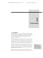
1. Getting Started
1.1 Overview
DataBridge SDR serial data recorders record RS-232 serial data to industrystandard mass storage using an MS-DOS™/Windows™-compatible FAT file
format. The SDR-CF (and SDR-OEM-CF) is an SDR equipped with a
Type I or II CompactFlash (CF) socket and is designed for use with
CompactFlash storage media.
The SDR is equipped with two serial ports. With terminal software on a PC,
you can use the configuration port to manage files, set up and communicate
with the data port, set date and time, modify output messages, download
data, manipulate the storage media, and enter record and stop modes. While
recording, you can also monitor recording using the configuration port.
During Record mode, the data port accepts RS-232C serial data from your
data source. For data sources that require initialization or querying, the SDR
can store and transmit up to eight user-defined messages. Each message is
independent and can be sent when recording starts, when recording stops, or
periodically at specific time intervals.
Both SDR ports support baud rates up to 230,400 bps and RTS/CTS
hardware handshaking for reliable high-speed communication. Your SDR is
5
NOTE: The data
source is a device that
transmits serial data
for use by a computer,
printer, or data logger.
also equipped with a real-time clock, power-saving features, non-volatile
memory, and a resume-on-power failure feature. The SDR features a onebutton front panel user interface that starts and stops recording.
1.2 Before you start
Before you start, be sure you have the following items available:
• DataBridge SDR-CF or SDR-OEM-CF board
• A 5VDC regulated or 7-30VDC power supply
• RS-232 DB9 serial cable(s)
• A computer or terminal with an available serial port
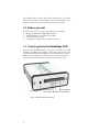
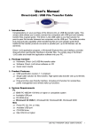
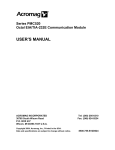
1.3 A quick guide to the DataBridge SDR
On the front of the SDR-CF are the CF socket, record button, and LED
indicators. The SDR can be toggled in and out of record mode using the
record button located on the front panel. The LED indicators show the
SDR’s current recording status. The data indicator flashes when data is
received and is used to verify data reception from your data source.
Record Button
Fault Indicator
Data Indicator
Figure 1.1. SDR-CF Front Panel Controls.
6
Power Indicator
Recording Indicator
SDR-CF/SDR-OEM-CF Configuration Guide rev 1.2
Configuring the DataBridge SDR-CF
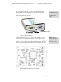
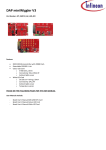
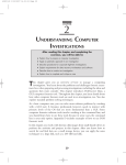
On the rear are two serial ports – one female nine-pin D-subminiature
connector (DB9F) for the configuration port and one male nine-pin Dsubminiature connector (DB9M) for the data port. The 7-30 VDC power
input is also located on the rear panel.
Data Port
(DB9M RS-232)
NOTE: The
configuration and data
ports can each operate
at different baud
rates.
Configuration Port
(DB9F RS-232)
Power
to PC serial port
from serial data source
GND
+7-18VDC
Figure 1.2. SDR-CF Rear Panel.
NOTE: Do not
remove front panel.
To enter the
enclosure, remove
back panel only.
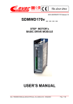
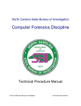
Inside the enclosure (See Figure 1.3), along the left-hand side is a 2-pin 5V
power connector and a 3V lithium battery. On the inside-right is a bank of
four switches for setting configuration port baud rate and handshaking (if
needed). You may also notice other connectors labeled API Port and JTAG
Port. These are used during manufacturing and custom applications. They
are not intended for general customer use.
Figure 1.3. SDR-CF Internal Connections and switches
(SDR-OEM-CF).
7
1.4 Deploying the DataBridge SDR
1.4.1
Connecting power to your SDR
The SDR starter kit includes a 120VAC power supply that connects via the
rear panel. If you use an alternate power source, it should be capable of
sourcing at least 200mA. When you apply power the power indicator should
light and the other indicators should flash in sequence.
1.4.2
Connecting to the configuration port
To configure your SDR, start by connecting the SDR’s configuration port to
an available serial port on your computer.
NOTE: Your
computer’s female
DB25 connector is
most likely a parallel
port, not a serial port.
Serial ports are found on the back of your computer. Most computers are
equipped with either a DB9 male (DB9M), or on older computers, a
DB25M connector. Male connectors have pins, while female connectors
have sockets. If your computer uses a serial mouse, it may already occupy
your DB9 male connector. Likewise, if your computer is equipped with an
external modem, it may occupy your DB25M connector.
If you are unable to locate your serial port(s), consult the documentation
included with your computer. If all of your computer’s serial port(s) are
occupied, contact your manufacturer or support provider for information
about adding a serial port to your computer. Using a serial to USB adaptor,
you could also connect through your computer’s available USB ports.
If your computer is equipped with a DB9M receptacle, connect the SDR's
configuration port (DB9F) your computer’s serial port using a standard
serial cable. If your computer’s available serial port is a DB25M connector,
you will need to purchase a DB9M to DB25F adapter, often referred to as
an AT adapter, to connect a 9-pin serial cable to your 25-pin serial port (the
adapter has DB9 male and DB25 female connectors).
Once you have located your serial port, you need to know whether your port
is configured for operation as COM1, COM2, COM3, or COM4 (some
computers even include COM5-COM8). In most cases, a port that uses a
DB9 male connector is configured as COM1 (or perhaps COM3), while a
DB25 male connector is configured as COM2 (or COM4). If one or more
of your computer’s ports are occupied by a mouse, modem, serial printer, or
other serial devices, you may need to explore your computer’s configuration
information and use a process of elimination to determine your port’s COM
designation.
1.4.3
Communications software
Now that the SDR is connected to your computer, configure
communications software (also known as terminal software) to communicate
with it. Typical communications software used is HyperTerminal™ which is
8
SDR-CF/SDR-OEM-CF Configuration Guide rev 1.2
Configuring the DataBridge SDR-CF
included with Microsoft Windows 95/98/NT 4.0/2000/XP/Vista. Many other
terminal programs are widely available for Windows, DOS, linux, and other
platforms. To access HyperTerminal, click the Windows start button and
choose Programs, then Accessories, then Communications, and then
HyperTerminal.
Configure HyperTerminal to communicate using the serial port you
connected to the SDR, the appropriate baud rate ( 9600 bps by default), and
the serial data format parameters (must be 8N1). See Section 3.2 if you wish
to change the SDR’s configuration port serial parameters from the default
9600 bps 8N1.
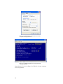
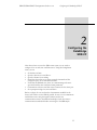
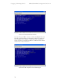
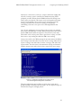
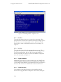
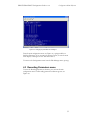
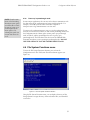
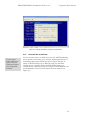
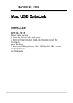
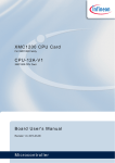
Once the SDR is connected to your computer and you are running terminal
software the SDR Configuration menu should appear (see Figure 1.) in your
terminal window. If you don’t see the Configuration menu, try typing
<Enter> or <Space> to refresh the display.
By default the SDR’s ANSI mode is on. ANSI mode results in a more clear
and readable display. The color user interface also continuously updates time
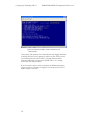
and status information. By default, HyperTerminal settings are configured to
communicate with the SDR. The default settings are pictured in Figures 1.4
and 1.5:
Figure 1.4. The default settings under “New Connection
Properties” in HyperTerminal.
9
Figure 1.5. The default settings under the New Connection
Properties tab in HyperTerminal.
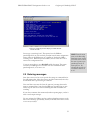
Figure 1.6. The SDR Configuration menu in HyperTerminal
with ANSI mode ON.
Congratulations! You are now talking to the SDR and can begin configuring
it for your application.
10
SDR-CF/SDR-OEM-CF Configuration Guide rev 1.2
Configuring the DataBridge SDR-CF
2
2. Configuring the
DataBridge
SDR-CF
Now that you have access to the SDR’s menu system, you are ready to
configure it for use with your serial data source. Using the Configuration
menu, you can:
•
•
•
•
•
•
•
Set the date and time.
Specify a directory to record files to.
Specify a filename for recording.
Ensure that the media you are using is properly formatted and has
enough free space to accommodate your data.
Verify that the SDR and your device are communicating at the same
speed and with the same serial data format parameters.
Communicate with your serial data source connected to the device port.
Set up output messages for your serial device.
Before you begin, be sure you have the documentation available for the
device you’ll connect to your SDR. If possible, be sure you can communicate
with the data source using the supplied software and/or your
communications software. An intimate knowledge of your data source's
communications standards will make connecting it to the SDR simple.
11
Configuring the DataBridge SDR-CF
SDR-CF/SDR-OEM-CF Configuration Guide rev 1.2
2.1 Setting date and time
TIP: For detailed
information about the
SDR configuration
menus, see Chapter 4.
The SDR features a real-time clock that reports a file’s last modified date
and time. The real-time clock is preset and battery-backed, so setting the
date and time is seldom necessary.
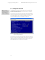
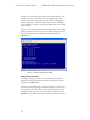
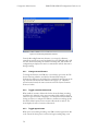
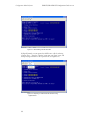
To set the time, type 1 at the menu prompt. Then, when prompted further,
enter the time in 24-hour format using two digits for each of hours, minutes,
and seconds (omit the colons (:) between each field). Press any key to
return to the SDR main menu. For an example, see Figure 2.1.
Figure 2.1. Setting the SDR’s time.
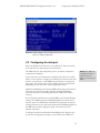
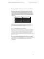
To set the date, type 2 at the menu prompt. Then, enter the date using two
digits for each of the month and day fields, and four digits for the year field
(omitting any hyphens or other characters). Press any key to return to the
main configuration menu. See Figure 2.2 for an example.
12
SDR-CF/SDR-OEM-CF Configuration Guide rev 1.2
Configuring the DataBridge SDR-CF
Figure 2.2. Setting the SDR’s date.
2.2 Configuring the data port
Before the SDR and your data source can communicate, they must interact
at the same data rate and using the same data format.
The SDR's data port and configuration port are, by default, configured to
communicate at 9600 bps.
If your data source can communicate at 9600 bps (also referred to as 9600
baud), it may be easiest to configure it for 9600 bps. For devices with a fixed
data rate, you will need to set the SDR's data port baud rate to match your
data source. You may also wish to choose a higher data rate (and hardware
handshaking) if your data source sends a high volume of data.
Hardware handshaking ensures that the SDR sends messages only when the
data source is ready to accept them. Likewise, hardware handshaking
prevents a data source from sending data when the SDR is not ready to
receive it.
Be sure that your serial data source and the SDR use the same handshaking
settings. If the SDR monitors the handshaking signal but your data source
does not send it, the SDR will wait indefinitely for "permission" to transmit
messages. Likewise, if your data source monitors the handshaking signals but
the SDR doesn't send the appropriate signal, the software may never
transmit output data.
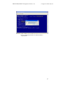
To change the baud rate and hardware handshaking for the data port, type
9, and select the appropriate settings to for your data source. When your
13
NOTE: The SDR uses
a serial data format of
eight data bits, no
parity, and one stop bit
(8N1).
Configuring the DataBridge SDR-CF
SDR-CF/SDR-OEM-CF Configuration Guide rev 1.2
desired settings are indicated, type <Enter> or <ESC> to save the settings
and close the window.
Figure 2.3. The Data Port Configuration prompt.
2.3 Specifying a filename and folder
By default, the SDR records data to a file called SDR-0000.DAT located in
the DATA subfolder in the CF card's root directory. You can keep this
filename or specify a new filename that reflects the data it contains. For
example, you may wish to use PRESSURE.TXT for pressure data or even a
name like TEMP0907.TXT for temperature data from September 2007.
Likewise, your choice of folder names may reflect something about the data
it contains.
Notes about filenames
When you enter a filename, it must conform to the FAT16 8+3 filename
format. This means that files contain up to 8 characters, a period ("dot"), and
up to three more characters. For example, BRIDGE.DAT, ABCDEFGH.123,
and 1 are all valid filenames, while DATA.FILE, and JOHNSMITH.TXT are
not. The SDR ignores characters you type that are not allowed in FAT16
filenames, such as: \/*|[].
You can also change
the filename and
folder by typing 6 at
the main menu, then 1
in the Recording
Parameters submenu.
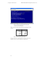
To specify the name of the file the SDR will use for recording data, type 7 at
the main menu prompt to enter the File System Functions submenu (see
Figure 2.4). You can use Option 3 to change directory without having to
retype the filename.
14
SDR-CF/SDR-OEM-CF Configuration Guide rev 1.2
Configuring the DataBridge SDR-CF
From the File System Functions menu, press 2. Then, when prompted,
backspace over the current filename/path and type a filename, pressing the
<Enter> key when finished or <Esc> to cancel changes. If your filename
is not 8+3 compliant, the SDR does its best to make it compliant. You can
return to the main menu by typing Q.
Figure 2.4. Changing the current filename.
2.4 Setting recording parameters
The SDR's recording parameters submenu allows you to control how and
when new files are created, how the SDR handles a full CF card, if incoming
data is date/time stamped, and how the SDR handles a power failure. To
enter the Recording Parameters submenu, press 6 from the main menu
prompt.
15
Configuring the DataBridge SDR-CF
SDR-CF/SDR-OEM-CF Configuration Guide rev 1.2
Figure 2.5. The Recording Parameters submenu.
Overwrite-oldest mode: When overwrite is enabled, the SDR will delete the
oldest file on the disk whenever recording starts and the CF card has less
than 1 megabyte of free disk space. Use this option with scheduled file
closing (see below) to configure the SDR as a circular buffer that contains
only the most recently received data.
Figure 2.6. The SDR configured as a circular buffering logger.
16
SDR-CF/SDR-OEM-CF Configuration Guide rev 1.2
Configuring the DataBridge SDR-CF
Append mode: If append mode is enabled, data will be recorded to the
current file whenever recording starts, resulting in one large file. New files
will only be created when the filename is modified via the configuration
menus.
Scheduled file closing: The SDR can be configured to automatically stop and
restart recording based on either a time interval (in seconds) or a file size (in
bytes).
Figure 2.7. Configuring the SDR to create a new file after every
1 megabyte (1048576 bytes) of data received.
17
Configuring the DataBridge SDR-CF
SDR-CF/SDR-OEM-CF Configuration Guide rev 1.2
Figure 2.8. Configuring the SDR to create a new file every hour
(3600 seconds).
Time stamping: This option is most commonly used when logging ASCII data
to add date and time to the beginning of each line of data, which is useful
for correlating data with other recorders. Incoming data lines will be
terminated with either a carriage return (ASCII code 13) or a carriage
return+line feed (ASCII code 10).
If you are unsure, it may be easiest to configure the SDR timestamping to
trigger on a line feed, and then reconfigure it for carriage return if you see
no time stamps in your data.
18
SDR-CF/SDR-OEM-CF Configuration Guide rev 1.2
Configuring the DataBridge SDR-CF
Figure 2.9. Configuring the time stamping for ASCII data with
CR+LF line ends.
Powering up in passthrough mode: This option forces the SDR into
passthrough mode (as if the user had pressed 8 from the main configuration
menu) whenever the SDR powers up, regardless of whether the SDR is
recording or not. When the option is enabled, the user must enter +++ to
return to the configuration menu.
If you are unsure how to use it,DO NOT enable this option. This option
can make your SDR appear to be broken. For more information about
passthrough mode, see section 4.1.5.
2.5 Entering messages
Some data sources need to receive specific data strings or commands before
they will transmit data. Other data sources send data continuously once they
are initialized with a specific string or command.
Your serial data source may also have the option of powering down with a
string or command that is sent when the SDR stops recording. Or you may
wish to stop the data source from transmitting data while the SDR is not
recording.
If your device transmits data continuously without requiring input, you don’t
need to send output messages.
You can configure the SDR to send up to eight independent messages to the
data source on startup, periodically, or both, on intervals from once a second
to once every 194 days.
19
NOTE: From the main
menu, in the Recording
Parameters menu option
you will be able to check
the state of power up in
passthrough mode on
menu option 6. By
selecting this option you
can turn this feature on
or off.
Configuring the DataBridge SDR-CF
SDR-CF/SDR-OEM-CF Configuration Guide rev 1.2
Messages are stored as ASCII text strings in non-volatile memory. To use
messages, first enter a text string for one of the eight messages. Then,
configure whether the message should be sent on when recording starts,
when recording stops, or at an interval specified in seconds. The SDR can
also be configured to append a carriage return <CR> and/or line feed <LF>
to any message.
To enter a new message, type 5 at the main menu prompt to enter the Edit
Messages submenu. To edit a message, type 1. When prompted, enter the
desired message number (0-7) and type a message followed by the
<Enter> key.
Figure 2.10. Changing message zero to “$1RD”.
Setting message parameters
To change a message’s parameters, type 2 at the menu prompt. When
prompted, enter the desired message number (0-7) and type a message
followed by the <Enter> key.
Output intervals: The SDR sends a message, then waits a specific amount of
time before sending the message again. When configuring a message, you
are prompted to enter this period, or output interval. For instance, if the
message should be output once every ten seconds, type 10 and press the
<Enter> key. To disable a message (but leave its contents intact), enter 0.
20
SDR-CF/SDR-OEM-CF Configuration Guide rev 1.2
Configuring the DataBridge SDR-CF
Initialization: Some devices “wake up” or begin continuously sending data
only after receiving a specific command, the initialization string. When
prompted, press Y to indicate that the SDR should send the message once
when it enters record mode. This feature can be used together with output
interval to both initialize a device with a specific message and send the
message periodically. This is useful for resetting or automatically
reinitializing a data source if its power is lost. Entering N disables this
feature.
Stop: In some applications you may wish to send a message to an attached
device when your SDR stops recording. When prompted, press Y to indicate
that the SDR should send the message once when it leaves record mode.
This feature can be used to power down or put a device to sleep, or tell the
data source to stop sending data while the SDR is not recording.
Carriage return and line feed: When prompted, enter Y to instruct the SDR to
add a carriage return and/or line feed to the end of a message. Many devices
require a carriage return and/or line feed after a message, while others may
require neither. Your data source’s documentation can help you determine
whether carriage returns and/or line feeds are required after query strings.
Figure 2.11. Configuring message zero for output every 10
seconds and append carriage return and line feed.
The main configuration menu includes an option (menu option 4) for
globally enabling or disabling output messages. Be sure output messages are
enabled when using the messaging feature.
21
Configuring the DataBridge SDR-CF
SDR-CF/SDR-OEM-CF Configuration Guide rev 1.2
2.6 Testing your configuration
TIP: Messages with
only a carriage return
(no line feed) after
them will appear to
overwrite previous
messages in your
terminal software. You
can enable your
communications
software’s "append
linefeeds to incoming
carriage returns"
feature to see these
messages properly.
To test your configuration, disconnect your terminal from the configuration
port and use a null modem adapter or cable to connect your terminal to the
data port. Your computer then becomes a data source.
Press the Record button to enter record mode. The SDR’s record indicator
will illuminate and the output messages you entered will be displayed once
or at the specified output intervals.
To ensure that recording is occurring, type several keystrokes on the
terminal or use the software’s ASCII text upload feature to send a text file.
The SDR’s data indicator should blink as you press keys, indicating data is
being received. When finished, press the record button again to stop
recording and inspect the file created on the CF card.
Note: The SDR will not echo data while it is being recorded, so you will not
see characters appear on-screen as you type. You can enable your terminal
software’s "local echo" or "full duplex" feature to view data as you send it.
22
SDR-CF/SDR-OEM-CF Configuration Guide rev 1.2
Operations
3
3. Operations
3.1 Record mode
When you press the record button or type R from the Configuration menu,
the SDR searches for the current file specified in the File System Functions
menu, creates it if necessary, and opens it. Once the SDR has successfully
opened the file, the record indicator turns on and the SDR enters record
mode.
Once in record mode, the SDR records any data received on the data port to
the open file. While in record mode, the SDR also transmits the messages
stored in nonvolatile memory at the specified intervals to the data source
connected to its data port.
3.1.1
Receiving data
The data indicator flashes when the SDR receives data. This indicator is
useful to ensure that the SDR is actually receiving data via the data port.
Note: this flashing indicator does not guarantee a correct baud rate.
Incorrect baud rates between the data source and SDR may still cause the
data indicator to flash.
23
Operations
3.1.2
SDR-CF/SDR-OEM-CF Configuration Guide rev 1.2
Stopping recording
Incoming data is appended to the open file as it is received until you stop
recording by either pressing the record button or typing S from the
Configuration menu. The SDR then closes the file, updates its directory
entry (recording file size, date, and time), and returns to stop mode.
3.1.3
Power failure and improper shutdowns
If the SDR loses power while in record mode, it returns to record mode after
power is restored. When powering up after a loss of power while recording,
the SDR waits about 5 seconds and prompts you to hit any key or the record
button to abort returning to record mode.
An improper shutdown may result in loss of data (due to sector buffering
and caching in the storage device) and minor allocation errors that can be
repaired using the MS-DOS™ SCANDISK.EXE utility, Norton Disk
Doctor™, or Windows 95/98/NT/2000/XP™ Explorer.
3.1.4
Full storage media
When the storage media’s first valid partition is full, the SDR returns to stop
mode unless overwrite-oldest mode is enabled, in which case the SDR will
delete the oldest file in the target folder and return to recording mode.
You can delete files on the target media using your computer or replace it,
then insert the media and press the record button and append data normally.
3.1.5
NOTE: If your storage
media was included
with SDR, it is already
formatted properly.
Formatting the storage media
If you have purchased a CF card, you may need to format it using MSDOS™, Windows 95/98/ME™, Windows NT/2000/XP™, or another
operating system that supports the FAT16 file system.
The SDR supports only the FAT16 file system. If your computer supports
the NTFS, FAT32, HPFS, or other advanced file systems, be sure your card
is formatted using conventional FAT16.
24
SDR-CF/SDR-OEM-CF Configuration Guide rev 1.2
Operations
Figure 3.1. Formatting a CompactFlash card using the FAT
(FAT16) file system instead of FAT32.
3.1.6
Partitions
In some cases, disks are partitioned to contain multiple "virtual" drives on a
single disk. Partitioning is sometimes done to overcome the 2 gigabyte size
limit in MS-DOS™ (and create multiple 2 gigabyte drives), support multiple
operating systems and file systems, or make more efficient use of disk space.
FDISK.EXE (included with MS-DOS™ and Windows 95/98™), Disk
Administrator (included with Windows NT/2000/XP/Vista™), Norton Disk
Doctor™, and Norton DiskEdit™ are useful tools for managing and
analyzing disk partitioning schemes.
The SDR supports both extended and primary FAT16 and VFAT partitions,
but always reads and writes files in the first partition it recognizes as FAT16
or VFAT.
3.1.7
Considerations for slow devices
Mass storage devices, particularly low-power and removable devices,
sometimes suffer from slow disk access times. Most notably, the IBM
MicroDrive™ may suffer from slow access times due to rotational latency
and power-saving features. CompactFlash card users need not worry
about access time considerations.
It is important to note that access times quoted by manufacturers are
averages. A worst-case access time can be ten times the number specified.
For instance, a drive or card with a 25-millisecond average access time may
sometimes require 250 milliseconds or more to access a sector.
25
Operations
SDR-CF/SDR-OEM-CF Configuration Guide rev 1.2
The SDR includes a 120-kilobyte buffer to store characters received during
slow disk accesses. The maximum disk access time before the SDR asserts
its handshaking signal, or characters are lost, can be calculated using
Equation 3.1.
t max ≅
120,000 bytes
average byte rate
Equation 3.1. Maximum disk access time.
The average byte rate for a serial data source that transmits data
continuously is given in Equation 3.2.
average byte rate =
bits
1 byte
×
second 10 bits
Equation 3.2. Average byte rate.
So, if a data source transmits data continuously at 9600 bps, the maximum
allowable disk access time is approximately 125 seconds. A 230400 bps data
source will only allow for 5 seconds of buffering, enough to potentially cause
data loss when an IBM MicroDrive returns from low-power shutdown
mode.
Most data sources transfer data in short bursts. For example, a device may
send a 10-byte message once per second. In this case, the average byte rate
is simply 10 bytes/second and the maximum disk access time becomes 50
seconds.
If your maximum disk access time exceeds your media’s worst-case access
time, you can expect occasional data loss. This is very rare.
3.2 Configuration Port settings
In some cases, you may wish to choose higher (or lower) data rates for the
configuration port.
For example, you may need a lower speed if you wish to configure, control,
and monitor your SDR remotely using a radio modem. You may need a
higher speed if you intend to download data through the serial port using
YMODEM or if you simply want a “snappier” menu display.
To change the configuration port baud rate, open the enclosure and use
switches S1-1, S1-2 and S1-3 to select a baud rate for the configuration port
and switch S1-4 to enable or disable RTS/CTS hardware handshaking. See
Table 3.1 for switch settings.
26
TIP: Enable hardware
handshaking on SDR
and your serial data
source when possible
to avoid data loss
when using slow
storage media.
SDR-CF/SDR-OEM-CF Configuration Guide rev 1.2
Operations
baud rate 0
baud rate 1
baud rate 2
RTS/CTS
handshake
enable
S1-1
S1-2
S1-3
S1-4
-
-
-
ON
2400 bps
OFF
OFF
OFF
-
4800 bps
ON
OFF
OFF
-
9600 bps
OFF
ON
OFF
-
19200 bps
ON
ON
OFF
-
38400 bps
OFF
OFF
ON
-
57600 bps
ON
OFF
ON
-
115200 bps
OFF
ON
ON
-
230400 bps
ON
ON
ON
-
Label
Switch Designator
RTS/CTS hardware
handshaking enable
Table 3.1. Configuration Port DIP switch settings.
3.3 Lithium battery maintenance
The SDR's real-time clock uses a small lithium battery to maintain time
when external power is unavailable. The life of this battery should exceed 5
years.
If you find your SDR is not keeping time correctly or that the time is
displayed with a question mark (?) after it when you power up, you may
need to replace the battery. If necessary, replace the battery with a
Panasonic CR2032, or equivalent, making sure the positive (+) face is in
contact with the battery clip. After replacing the battery be sure to reset the
SDR’s time and date.
27
SDR-CF/SDR-OEM-CF Configuration Guide rev 1.2
Configuration Menu Reference
4
4. Configuration
Menu
Reference
You can use menu functions to manage files, configure and communicate
with the device attached to the data port, set date and time, set up output
messages, download data, configure the storage media, and control the SDR
without using the record button.
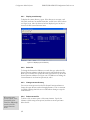
4.1 Main Configuration Menu
The SDR's core functions are accessed from the Configuration menu (see
Figure 4.1) using terminal software. The Configuration menu includes
functions for controlling both the SDR and the attached device. A number
of the Configuration menu items either prompt for input or execute
immediately, and therefore have no associated sub-menu.
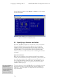
The Configuration menu also provides feedback during recording. Status
fields, on the right-hand side of the Configuration menu, indicate
approximate recorded file size in bytes, bytes dropped because of buffer
overflow (ideally zero), and a telltale for the minimum free space in the
buffer (120 kilobyte maximum). In addition, the logic states of the RTS,
CTS, and DTR lines of the data port are displayed. The DTR line is
designed to source +5VDC for optionally supplying low-power devices
(500mA max).
29
Configuration Menu Reference
SDR-CF/SDR-OEM-CF Configuration Guide rev 1.2
Figure 4.1. The DataBridge SDR-CF configuration menu.
4.1.1
Set Time
To update the real-time clock’s time, type 1 at the menu prompt. When
prompted further, enter the time in 24-hour format using two digits for each
of hours, minutes, and seconds (omit the colons (:) between each field).
Press any key to return to the SDR-CF main menu. For an example, see
Figure 2.1.
4.1.2
Set Date
To update the real-time clock’s date, type 2 at the menu prompt. When
prompted further, enter the date in MM/DD/YYYY format using two digits
for each for month and day, and four digits for year (omit the slash (/)
between each field). Press any key to return to the SDR-CF Configuration
menu. For an example, see Figure 2.2.
4.1.3
Toggle ANSI Mode
ANSI mode provides an easy to read user interface for your SDR-CF and is
enabled (or disabled) by typing 3 from the Configuration menu. Make sure
you have ANSI mode enabled in your terminal software for proper display of
the menus. The current state of ANSI mode is indicated on the menu.
4.1.4
Toggle Messages
For convenience and testing, all messages can be globally activated or
deactivated by typing 4 from the Configuration menu. Globally turning the
30
SDR-CF/SDR-OEM-CF Configuration Guide rev 1.2
Configuration Menu Reference
messages off does not change their settings, but overrides the current
message parameters. The current state of the messages is indicated.
4.1.5
Enter Serial Passthrough Mode
Serial passthrough mode provides a means for communicating with the
device connected to the data port. To enter passthrough mode, press 8 from
the main menu. To return to the main menu, type +++, then wait two
seconds without typing for the menu to reappear. The LED on the front of
the unit will blink incessantly to indicate that the SDR is in passthrough
mode.
4.1.6
Configure Data Port for Attached Device
To set the baud rate for the data port, type 9, and then select a baud rate
from the displayed list (2400, 4800, 9600, 19200, 38400, 57600, 115200,
230400 bps). Select a baud rate that matches the rate used by the device
attached to the data port. Typing a 1 or 0 turns hardware handshaking on or
off. The current settings are displayed at the bottom of the input window.
Pressing <Enter> or <ESC> saves the settings and returns to the
Configuration menu.
Figure 4.2. Data port configuration.
4.1.7
Start/Stop Recording
Like the record button, the main menu commands R and S are used to
immediately enter record and stop modes. The R menu option shows the
current state of recording (on or off).
31
NOTE: Incorrect
handshaking settings
may cause the SDR to
become unresponsive
during passthrough
mode. Particularly,
enabling RTS/CTS
handshaking for a
device that doesn’t
support hardware
handshaking may
cause these hangs. If
your SDR hangs
during passthrough
mode, remove power
for five seconds, and
then reapply power.
Configuration Menu Reference
SDR-CF/SDR-OEM-CF Configuration Guide rev 1.2
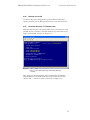
4.2 Edit Messages menu
To enter the Edit Messages submenu, type 5 from the Configuration menu.
The Edit Messages menu appears (see Figure 4.3).
To edit a message’s contents, type 1. Select the number of the message you
would like to edit and type in the new message contents. Pressing <Enter>
saves the message and returns you to the Edit Messages menu.
Figure 4.3. Entering text for message 0.
To edit a message’s parameters, type 2 and select the number of the
message you would like to change the parameters for. Follow the prompts to
set the output interval, whether to send the message on initialization
(entering record mode), whether to send the message when stopping (exiting
record mode), and whether to append carriage returns and/or line feeds.
32
SDR-CF/SDR-OEM-CF Configuration Guide rev 1.2
Configuration Menu Reference
Figure 4.4. Changing the parameters for message 0.
From the main configuration menu (see Figure 4.1), typing 4 enables or
disables all messages. If you are using the message feature, be sure the main
menu displays “messages are ON” after menu item 4.
To return to the Configuration menu from the Edit Messages menu, press Q.
4.3 Recording Parameters menu
To enter the Recording Parameters submenu, press 6 from the main
configuration menu. The Recording parameters submenu appears (see
Figure 4.5).
33
Configuration Menu Reference
SDR-CF/SDR-OEM-CF Configuration Guide rev 1.2
Figure 4.5. The Recording Parameters submenu.
From the Recording Parameters submenu, you can specify a filename,
control how new files are created and named, how the SDR deals with a full
CF card, whether timestamps are added to incoming data, and whether the
configuration port displays the menu or communicates with the data source
during recording.
4.3.1
Change current filename
To change the filename your SDR uses to record data, type 2 from the File
System Functions submenu, and edit the filename/folder using the
backspace key. When you are finished, the specified file name appears at the
top of the File System Functions submenu (see Figure 4.5). This menu
option functions exactly the same as menu 1 in the File System Functions
menu (see below).
4.3.2
Toggle overwrite-oldest mode
When enabled, overwrite-oldest mode checks the media during recording
and deletes the oldest file in the current recording folder whenever the CF
card's free space is less than 1 megabyte. Use this option with scheduled file
closing (see below) to configure the SDR as a continuous-recording circular
data buffer. Menu option 2 turns overwrite-oldest mode on and off. The
menu displays the state of overwrite-oldest mode.
4.3.3
Toggle append mode
When power is lost during recording, your SDR can either append new data
to the current file when power is restored or begin recording using a new
34
SDR-CF/SDR-OEM-CF Configuration Guide rev 1.2
Configuration Menu Reference
file. Menu option 3 turns append mode on and off. The menu displays the
state of append mode.
When append mode is off, the SDR will generate a name for the new file
based on the current filename. It does this by incrementing the filename
using the characters 0 through 9 and A through Z. If the target filename
without extension is less than eight characters and append mode is off, the
SDR pads the name with zeros. Examples of filename generation are shown
in Figure 4.6.
Before Incrementing
After Incrementing
BRIDGE.DAT
BRIDGE01.DAT
BRIDGE01.DAT
BRIDGE02.DAT
BRIDGE09.DAT
BRIDGE0A.DAT
BRIDGE0Z.DAT
BRIDGE10.DAT
BRIDGE10.DAT
BRIDGE11.DAT
Figure 4.6. Generating filenames when append mode is off.
Note: A disk’s root directory typically holds only 512 directory entries. To
avoid exceeding this 512 file limit, do not record using the root directory in
environments where power will be lost frequently.
4.3.4
Set scheduled file close parameters
The SDR can periodically close and reopen or create new files automatically.
This is useful to ensure that data is committed to the disk, especially when
recording at low data rates. When used with append mode off, scheduled
file closings ensure that your data files are a manageable size. Each file is
stamped with the date and time when closed, which can later provide useful
diagnostic information.
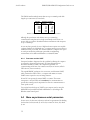
Files can be closed on a time or file size basis. To schedule file closings, type
4 from the Recording Parameters submenu. When prompted, either chose
to close files based on file size or time interval (up to 16777216 seconds). In
Figure 4.7 the user is specifying that the file will be closed every hour of
recording time.
35
SDR-CF/SDR-OEM-CF Configuration Guide rev 1.2
Configuration Menu Reference
Figure 4.7. Configuring scheduled file close for every 3600
seconds (1 hour) of recording time.
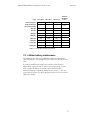
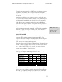
Table 4.1 provides useful conversion factors for specifying file-closing
intervals.
Interval
Seconds
1 second
1
1 minute
60
1 hour
3600
1 day
86400
1 week
604800
1 month*
2629800
6 months*
15778800
*based on a 365¼-day year
Table 4.1. Common file-closing time intervals.
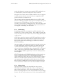
In Figure 4.8, the user is specifying that the file will be closed once a
megabyte of data is received (1024×1024=1048576 bytes).
36
SDR-CF/SDR-OEM-CF Configuration Guide rev 1.2
Configuration Menu Reference
Figure 4.8. Configuring scheduled file close every 1 megabyte.
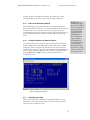
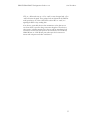
4.3.5
Time stamp incoming lines
The SDR allows you to add the time and date to each line of incoming data.
Time stamping is triggered by reception of a character of your choice.
Typically, the line feed character (ASCII code 10) is a good choice since a
line feed character usually precedes each new line from the data source (see
Figure 4.9).
However, some devices output only a carriage return (ASCII code 13) at the
end of each line. Consult your documentation or try line feed, then carriage
return if you don't see time stamps in your data.
Time stamps are written in MM/DD/YY HH:MM:SS format.
37
Configuration Menu Reference
SDR-CF/SDR-OEM-CF Configuration Guide rev 1.2
Figure 4.9. Enabling time stamping of incoming data after the
line feed (LF) character.
Figure 4.10 shows an ASCII download of a file with time stamping enabled.
Figure 4.10. An example of a file recorded with time stamping
enabled.
38
SDR-CF/SDR-OEM-CF Configuration Guide rev 1.2
NOTE: From the main
menu, in the Recording
Parameters menu option
you will be able to check
the state of power up in
passthrough mode on
menu option 6. By
selecting this option you
can turn this feature on
or off.
4.3.6
Configuration Menu Reference
Power up in passthrough mode
In some unique applications, the user may wish to always communicate with
the data source via the configuration port using passthrough mode. For
example, if the SDR is placed "in-line" between a computer or
microprocessor to log communications to or from each.
To return to the configuration menu, enter +++ via the configuration port,
then wait 2 seconds as you would if you had entered passthrough mode from
the Configuration menu. Menu option 6 turns power up in passthrough
mode on and off, and the menu displays the state of power up in
passthrough mode. The LED located on the front of the SDR will blink
incessantly to indicate you are operating in passthrough mode. DO NOT
USE THIS OPTION IF YOU ARE UNSURE WHAT IT DOES.
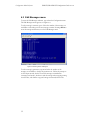
4.4 File System Functions menu
To enter the File System Functions submenu, press 7 from the
Configuration menu. The File System Functions submenu appears (see
Figure 4.5).
Figure 4.11. The File System Functions submenu.
Using the File System Functions menu, you can display a directory of files,
change filename or target directory, delete and rename files, and download
or view files.
39
Configuration Menu Reference
4.4.1
SDR-CF/SDR-OEM-CF Configuration Guide rev 1.2
Display root directory
To display the current directory, type 1. If the directory is not empty, each
file’s name, attributes, last modified time/date, and file size in bytes is shown
(see Figure 4.12). Once the directory has been displayed, press any key to
return to the File System Functions menu.
Figure 4.12. Displaying the root directory.
4.4.2
Select file
To change the filename the SDR uses to record data, type 2 from the File
System Functions submenu and edit the contents using the Backspace key.
When you are finished, the specified file name appears at the top of the File
System Functions submenu (see Figure 4.11). In addition to recording, the
current filename is used in menu options 4, 5, and 7.
4.4.3
Change current directory
You can use menu option 3 from the File System Functions submenu to
change the target directory without changing filenames. This is convenient
for quickly changing where files are recorded without having to retype the
entire filename.
When using menu
options 4 and 5, if the
specified file is not
found, the SDR simply
returns to the File
System Functions
menu.
4.4.4
Delete current file
To delete a file, use menu option 7 file system functions. Specify the
filename to delete using menu option 2, and then use menu option 4 to
delete the file.
40
SDR-CF/SDR-OEM-CF Configuration Guide rev 1.2
4.4.5
Configuration Menu Reference
Rename current file
To rename a file on the storage media, specify its filename using menu
option 2, and then press 5. When prompted, enter a new name for the file.
4.4.6
Download directory via Ymodem batch
Menu option 6 allow you to download all files in the current directory using
terminal software. To initiate a Ymodem download, type 6 and wait for the
"begin your download" message (see Figure 4.13).
Figure 4.13. The SDR ready to begin downloading files using
Ymodem.
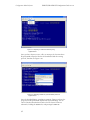
Then, using your terminal software, start a Ymodem batch download. In
HyperTerminal you can download the disk using Ymodem by selecting
“Receive File…” from the “Transfer” menu item (see Figure 4.14).
41
Configuration Menu Reference
SDR-CF/SDR-OEM-CF Configuration Guide rev 1.2
Figure 4.14. Preparing to download a directory using
HyperTerminal.
Once you have chosen to receive a file, you must specify a location where
HyperTerminal will put the files that are downloaded and the receiving
protocol, Ymodem (see Figure 4.15).
Figure 4.15. Selecting Ymodem as your file transfer protocol in
HyperTerminal.
Once the download begins, everything is automatic. Figure 4.16 shows the
progress menu HyperTerminal displays while the downloading. You can
cancel a Ymodem download and return to the File System Functions
submenu by holding the <Ctrl> key and pressing X (Ctrl-X).
42
SDR-CF/SDR-OEM-CF Configuration Guide rev 1.2
Configuration Menu Reference
Figure 4.16. Ymodem download in progress in HyperTerminal.
4.4.7
You may wish to
disable ANSI mode
(option 3 from the
Configuration menu)
when using ASCII
download.
Download file as ASCII text
You can use menu option 7 to download or view a file. ASCII downloading
doesn’t provide error checking, but is useful for displaying short files or for
downloading using terminal software that doesn’t support Ymodem. To
initiate an ASCII download, type 7. When the "begin your download"
message appears, (optionally) initiate an ASCII download using your
terminal software, and then press any key to begin or hold the Ctrl key and
press C (Ctrl-C) to return to the File System Functions submenu (see
Figure 4.17).
43
Configuration Menu Reference
SDR-CF/SDR-OEM-CF Configuration Guide rev 1.2
Figure 4.17. Downloading a file as ASCII text.
In HyperTerminal, you can capture the ASCII text to a file by selecting
“Capture Text…” from the “Transfer” menu item (see Figure 4.18), and
then specifying a filename for the captured text (see Figure 4.19).
Figure 4.18. Preparing to download file as ASCII text using
HyperTerminal.
44
SDR-CF/SDR-OEM-CF Configuration Guide rev 1.2
Configuration Menu Reference
Figure 4.19. Specifying a filename for an ASCII file transfer in
HyperTerminal.
45
SDR-CF/SDR-OEM-CF Configuration Guide rev 1.2
Service and Support
5
5. Service and
Support
5.1 Exception Codes
The following are common error codes encountered when using DataBridge
SDR-CF and SDR-OEM-CF products. To determine which error has
occurred, watch the "exception" indicator on the SDR's front panel and
count the number of rapid blinks. Each sequence is separated by a 1 second
pause in the blink pattern.
Exception 2: Root Directory Full
A FAT16 root directory can have only 512 directory entries (fewer if long
filenames are used). Delete files from the root directory, or record to a
subfolder in the root directory to overcome this limitation.
Exception 3: Disk Full
The disk has no (or almost no) available space for files. Delete files from the
disk to ensure space is available.
Exception 4: Bad Boot Record
Occurs when the disk is completely unformatted or formatted for FAT32.
Use format /FS:FAT from the Windows command prompt to ensure
proper FAT16 formatting.
47
Service and Support
SDR-CF/SDR-OEM-CF Configuration Guide rev 1.2
Exception 5: Hardware Error
Usually occurs when the SDR-CF cannot reset the CompactFlash card. Try
ejecting and reinserting the card or using a new card and contact Acumen if
problem persists.
Exception 6: EEPROM Error
Rare hardware error. Contact Acumen to discuss repair or replacement.
Exception 7: Cache Error
Rare hardware error. Contact Acumen to discuss repair or replacement.
Exception 8: Buffer Error (firmware error)
Rare error that may occur in customized or beta firmware versions. Contact
Acumen to report.
Exception 9: Tasking Error (firmware error)
Rare error that may occur in customized or beta firmware versions. Contact
Acumen to report.
Exception 10: ATA/CompactFlash Error
The CompactFlash media has reported a fatal error to the SDR-CF.
Reinsert/replace the media and contact Acumen if problem persists.
Exception 11: Directory Creation Error
Rare. The SDR-CF cannot create the subdirectory files are to be recorded
to. Try using a different directory name or reformatting the media.
Exception 12: FAT12 File System Detected
The SDR-CF has determined that the CF card was formatted using the
FAT12 file system, which is unsupported. Reformat the CF card using the
/A:512 option (Windows 2000/XP) and retry. (Occurs only in firmware
revisions 8.7 and higher)
Exception 13: FAT32 File System Detected
The SDR-CF has determined that the CF card was formatted using the
FAT32 file system, which is unsupported. Reformat the CF card using the
/FS:FAT option (Windows 2000/XP) and retry. (Occurs only in firmware
revisions 8.7 and higher)
48
SDR-CF/SDR-OEM-CF Configuration Guide rev 1.2
Service and Support
5.2 Contacting Acumen Instruments
Corporation
5.2.1
Technical support
Service and technical support can be reached between the hours of 9AM and
5PM (Central Standard Time) Monday through Friday. Acumen Instruments
Corporation can be reached at the following phone numbers:
(515) 296-5366 (voice)
(515) 296-3554 (fax)
5.2.2
U.S. Mail
Acumen Instruments Corporation can be reached by mail at:
Acumen Instruments Corporation
2625 N. Loop Drive Suite 2200
Ames, IA 50010
USA
5.2.3
E-mail
Acumen Instruments Corporation can be reached via e-mail at:
[email protected]
5.2.4
World Wide Web
Acumen Instruments Corporation maintains a web site containing product
information and downloads:
http://www.acumeninstruments.com
5.3 Returning Equipment
Before returning equipment to Acumen Instruments Corporation, please call
for an RMA number and shipping information. This allows us to plan for
your shipment in order to provide the best possible service. When returning
equipment, please include a note indicating the symptoms of the failure and
any other pertinent information.
49
Service and Support
SDR-CF/SDR-OEM-CF Configuration Guide rev 1.2
5.4 Warranty
5.4.1
One year warranty
Acumen Instruments Corporation warrants this product to be free from
defects in materials and workmanship for a period of one (1) year from the
date of shipment. During the warranty period, Acumen Instruments
Corporation will, at its option, either repair or replace products that prove to
be defective.
5.4.2
Exclusions
This warranty shall not apply to any defect, failure or damage caused by
misuse, abuse, improper application, alteration, accident, disaster,
negligence, use outside of the environmental specifications, improper or
inadequate maintenance, or incorrect repair or servicing not performed or
authorized by Acumen Instruments Corporation.
5.4.3
Limitations
ACUMEN INSTRUMENTS CORPORATION SHALL IN NO EVENT HAVE
OBLIGTIONS OR LIABILITIES TO BUYER OR ANY OTHER PERSON FOR LOSS OF
PROFITS, LOSS OF USE OR INCIDENTAL, SPECIAL, OR CONSEQUENTIAL
DAMAGES, WHETHER BASED ON CONTRACT, TORT (INCLUDING
NEGLIGENCE), STRICT LIABILITY, OR ANY OTHER THEORY OR FORM OF
ACTION, EVEN IF ACUMEN INSTRUMENTS CORPORATION HAS BEEN ADVISED
OF THE POSSIBILITY THEREOF, ARISING OUT OF OR IN CONNECTION WITH
THE SALE, DELIVERY, USE, REPAIR, OR PERFORMANCE OF THIS PRODUCT
(INCLUDING EQUIPMENT, DOCUMENTATION AND SOFTWARE). IN NO EVENT
SHALL THE LIABILITY OF ACUMEN INSTRUMENTS CORPORATION ARISING IN
CONNECTION WITH ANY PRODUCT EXCEED THE ACTUAL AMOUNT PAID FOR
SUCH A PRODUCT.
THIS WARRANTY IS IN LIEU OF ALL OTHER WARRANTIES, WRITTEN OR ORAL,
EXPRESSED OR IMPLIED, INCLUDING IMPLIED WARRANTIES OR
MERCHANTABILITY OR FITNESS FOR A PARTICULAR PURPOSE.
50
SDR-CF/SDR-OEM-CF Configuration Guide rev 1.2
Serial Port Basics
A
A.Serial Port
Basics
A.1
Serial specifications
Serial data is any data that is sent one bit at a time using a single electrical
signal. In contrast, parallel data is sent 8, 16, 32, or even 64 bits at a time
using a signal line for each bit. Data that is sent without the use of a master
clock is said to be asynchronous serial data.
Several communications standards exist for the transfer of asynchronous
serial data. Common PC’s transfer data using the EIA RS-232C (also known
as V.28 or V.24). Updated versions of this standard include RS-232D and
EIA/TIA-232E, but most literature still refers to the RS-232C or RS-232
standard.
Other asynchronous serial standards in common use include RS-422, RS423, and RS-485. These standards allow higher data rates and longer cable
lengths than RS-232 and are common in industrial settings.
A.2
Data rates
The baud rate for a serial connection is the number of bits that are
transmitted per second. It is specified in bits/second or baud. For example, a
9600 baud serial link transfers 9600 bits per second.
51
SDR-CF/SDR-OEM-CF Configuration Guide rev 1.2
Serial Port Basics
The EIA RS-232C standard permits data rates up to 19200 bps and cable
lengths up to 400 meters (but not both).
data rate
(bps)
19200
9600
4800
2400
1200
600
maximum distance
(meters)
(feet)
15
45
25
76
50
152
100
304
200
608
400
1216
Table A.1. Data rates and distances for RS-232 communications.
Although the specification only defines rates up to 19200 bps,
communication using data rates as high as 230400 bps and a short (<2
meter) cable are common. Standard modems communicate with computers
at up to 115200 bps.
As you may have guessed, the use of high baud rates requires more capable
computer hardware. At high baud rates, a computer must process as many as
23000 characters per second. The constant attention a computer must pay to
its serial port makes this problematic particularly in multitasking
environments such as Microsoft Windows 3.1/95/98/NT/2000.
A.2.1
Data rates and the UART
Computer hardware designers solve this problem by allowing the computer
to respond to characters less frequently. A Universal Asynchronous
Receiver/Transmitter (UART), the component responsible for
communicating via RS-232, may contain several bytes of memory called a
FIFO (first-in, first-out memory).
The original IBM PC (and many of its successors) used the 8250 UART,
which contained no FIFO. That is, a computer with 8250 (or 16450)
UART’s must respond to every incoming character.
Newer PC’s incorporate the 16550 UART or a variant. The 16550
incorporates a 16-byte FIFO and is mandatory for communications at
speeds above 9600 bps and is important for error-free communications at
lower speeds as well.
You can find out which type of UART’s your computer uses by using the
MSD.EXE tool provided with DOS and Windows or by looking in the
Windows 95/98 control panel.
A.3
More asynchronous serial parameters
In most cases, the data rate in bytes/second can be approximated by dividing
the baud rate (in bits/second) by 10. If a byte consists of 8 bits, why divide
by 10?
52
SDR-CF/SDR-OEM-CF Configuration Guide rev 1.2
Serial Port Basics
To transfer data asynchronously, the UART frames the 8 data bits between a
stop bit and a start bit. The start bit is always a zero, while the stop bit is
always a one. So, a byte of data sent serially is made up of 10 bits instead of
the usual 8.
Asynchronous serial devices can communicate using 7 or 8 data bits, and 1,
1½, or 2 stop bits. To further complicate matters, devices can also employ a
parity bit instead of an eighth data bit to check for errors. Even parity
systems transmit a one when the sum of the seven bits is an even number,
while odd parity systems transmit a one when the sum is odd. Still more
exotic systems may specify “mark” or “space” parity, where the parity bit is
always a one or zero, respectively.
What does all of this mean? Device vendors usually specify their data rate
and format using statements like “9600, 8N1”, which translates to 9600 bps,
8 data bits, no parity, and 1 stop bit or “19200, 7E1”, which translates to
19200 bps, 7 data bits, even parity, and 1 stop bit.
A.3.2
DTE and DCE
The RS-232 specification defines two classes of devices: data terminal
equipment (DTE) and data communication equipment (DCE). Your
computer’s serial port is configured for DTE operation, since the computer
acts as a terminal. Modems and many other serial devices are configured as
DCE, since they are communications equipment.
What’s the difference? A DTE device’s TD signal means “I transmit data on
this line.” A DCE’s TD signal can be read “You (the DTE) transmit data to
me on this line.” A DTE’s RD signal means “I receive data on this signal
line.” A DCE’s RD line means, “You, the DTE, will receive the data I
transmit on this signal line.” Sound confusing?
A look at a the DB9 connector pinouts and signal direction with respect to
DTE (e.g. your computer) makes things a little more clear.
signal name
transmitted data
received data
request to send
clear to send
data terminal ready
data set ready
data carrier detect
ring indicator
signal ground
TD
RD
RTS
CTS
DTR
DSR
DCD
RI
GND
pin number
25-pin
9-pin
2
3
3
2
4
7
5
8
20
4
6
6
8
1
22
9
7
5
direction
DTE→DCE
DTE←DCE
DTE→DCE
DTE←DCE
DTE→DCE
DTE←DCE
DTE←DCE
DTE←DCE
Table A.2. Pinouts for 9-pin and 25-pin serial connectors.
The cable that connects DTE devices (such as your computer) and DCE
devices (such as your modem) is simple. It connects the TD pin to TD, pin
RD to RD, etc. A cable that connects DTE to DTE or DCE to DCE must
connect the TD to RD and RD to TD. This cable is referred to as a null
53
NOTE: Most serial
devices format of eight
data bits, no parity,
and one stop bit
(8N1).
SDR-CF/SDR-OEM-CF Configuration Guide rev 1.2
Serial Port Basics
modem cable because it can connect two terminals (DTE’s) without the use
of modems (DCE’s). Note that GND pins are always connected.
Most devices have female connectors (DB9 or DB25) if they are configured
for DCE operation and male connectors if they are configured for DTE
operation, but this is not always the case.
There is a simple trick for determining whether a device is DTE or DCE.
Connect a voltmeter’s ground line to the connector’s GND pin. Then, probe
the voltage on the TD and RD pins. If the TD pin voltage is small (3V<Vin<+3V), the device is configured to receive data on the TD pin, and
thus is a DCE device. Likewise, if the RD pin voltage is small, the device is
receiving data on the RD pin, and thus is DTE.
A.3.3
Handshaking
Handshaking signals by the receiving device to tell the transmitter “I am
ready for data” or “I am not ready for data.” These signals are optional: the
receiver may always be ready for data or may choose to simply discard data it
couldn’t process.
A DTE device asserts the “request to send” (RTS) signal when it is ready to
receive data and deasserts it when it cannot accept data. Likewise, a DCE
device asserts “clear to send” (CTS) when it is ready to receive data. The
RTS and CTS signals form a handshaking pair, and their use constitutes
RTS/CTS handshaking.
The “data terminal ready” (DTR) signal, asserted by the DTE, and the “data
set ready” (DSR) signal, asserted by the DCE serve similar functions and
constitute DTR/DSR handshaking. A DTE or DCE devices may employ
either or both forms of handshaking. Often, deasserting RTS or CTS signals
“micro” events, such as a buffer that is full but will be empty soon, while
deasserting DTR or DSR may signal “major” events such as that power has
not been applied.
RTS/CTS handshaking and DTR/DSR handshaking are both referred to as
hardware handshaking. Another form of handshaking, XON/XOFF or
software handshaking, requires that the receiver send a character (Control-S,
ASCII 19) to halt data transfer and another character (Control-Q, ASCII
17) to resume transfer. Although this method eliminates the need for the
RTS, CTS, DTR, or DSR signals, it suffers from slow response time by the
receiver and renders 2 characters of the 256-character ASCII set unusable.
A.3.4
Voltage levels
For noise immunity and long cable lengths, RS-232 devices convert
TTL/CMOS-level signals (0V=logic zero, +5V or +3.3V=logic one) to
higher voltage bipolar signals. For the TD and RD signal lines, RS-232
devices use a voltage between –3V and –25V to transmit a one and a voltage
between +3V and +25V to transmit a zero. For the other signal lines (RTS,
54
SDR-CF/SDR-OEM-CF Configuration Guide rev 1.2
Serial Port Basics
CTS, etc.), RS-232 devices use +3V to +25V to assert the signal and –3V to
–25V to deassert the signal. These voltage levels are defined in the EIA/TIA232E specification. So, when a DTE devices drives RTS at –9.50V, it is
signaling the DCE to stop sending data.
A few devices, particularly devices that communicate at low data rates or
over short cables, bypass the voltage conversion altogether. These devices
often require “computer interface kits” that are really no more than a level
converter in a box. These serial ports are often referred to as TTL RS-232,
CMOS RS-232, or 5 Volt RS-232 ports and require level converters to
interact with computers and other serial devices.
55
DataBridge SDR User’s Manual rev 1.2
SDR-CF and SDR-OEM-CF Specifications
B
B.SDR-CF and
SDR-OEM-CF
Specifications
B.1
Electrical specifications
SDR-CF requires a 7-30 VDC power source or a regulated +5VDC power
source (SDR-OEM-CF). Connectors J7 and J1 are present on both the
SDR-CF and SDR-OEM-CF. J1 is inaccessible on the SDR-CF without
removing the enclosure.
SDR-CF/SDR-OEM-CF
SDR-OEM-CF circuit board
+7-30 VDC
+5 VDC
100mA
100mA
Table B.1. DataBridge SDR-CF power consumption with
CompactFlash card installed.
B.1.5
J7 rear power receptacle pin configuration
pin
Tip
ring
Function
+7-30 VDC
Ground
Table B.2. The SDR-CF/SDR-OEM-CF rear power receptacle pin
configuration.
57
SDR-CF and SDR-OEM-CF Specifications
B.1.6
SDR-CF/SDR-OEM-CF Configuration Guide rev 1.2
J1 power receptacle pin configuration
pin
1
2
Function
+5.0 VDC
Ground
Table B.3. The SDR-OEM-CF power receptacle pin configuration.
B.2
Serial communications
Serial Port
electrical interface compliance
data rates
stop bits
Parity
Handshaking
EIA/TIA-232E and V.28
2400, 4800, 9600, 19200, 38400,
57600, 115200, 230400 bps
1
None
RTS/CTS
Table B.4. Serial communications specifications for the SDR-CF.
B.3
CompactFlash socket
CompactFlash type
storage capacity
Type I or Type II
True IDE
limited only by storage device and FAT file
system
Table B.5. CompactFlash socket specifications for the SDR-CF.
B.4
Mechanical Specifications
SDR-CF
Dimensions
Weight (without CF card)
Enclosure Material
SDR-OEM-CF circuit board
Dimensions
Weight (without CF card)
4.875” L × 3.50” W × 1.25” H
(12.3 cm × 8.5 cm × 3.2 cm)
approx. 6.0 oz. (170 grams)
Aluminum extrusion
4.50” L × 3.00” W × 0.60” H
(11.4 cm × 7.6 cm × 1.0 cm)
approx. 3.0 oz. (85 grams)
Table B.1. SDR-CF and SDR-OEM-CF mechanical specifications.
58
DataBridge SDR User’s Manual rev 1.2
SDR-CF and SDR-OEM-CF Specifications
Notes:
59